EP3398570B1 - Stütze und dafür verwendetes einsteckverbindungselement - Google Patents
Stütze und dafür verwendetes einsteckverbindungselement Download PDFInfo
- Publication number
- EP3398570B1 EP3398570B1 EP18165395.7A EP18165395A EP3398570B1 EP 3398570 B1 EP3398570 B1 EP 3398570B1 EP 18165395 A EP18165395 A EP 18165395A EP 3398570 B1 EP3398570 B1 EP 3398570B1
- Authority
- EP
- European Patent Office
- Prior art keywords
- fitting
- joint mechanism
- wearer
- brace
- fitting member
- Prior art date
- Legal status (The legal status is an assumption and is not a legal conclusion. Google has not performed a legal analysis and makes no representation as to the accuracy of the status listed.)
- Not-in-force
Links
- 230000007246 mechanism Effects 0.000 claims description 50
- 230000001105 regulatory effect Effects 0.000 claims description 33
- 210000000544 articulatio talocruralis Anatomy 0.000 claims description 29
- 230000033001 locomotion Effects 0.000 claims description 25
- 210000000988 bone and bone Anatomy 0.000 claims description 10
- 210000000689 upper leg Anatomy 0.000 claims description 9
- 210000002414 leg Anatomy 0.000 description 7
- 238000010586 diagram Methods 0.000 description 6
- 230000006870 function Effects 0.000 description 5
- 238000003780 insertion Methods 0.000 description 4
- 230000037431 insertion Effects 0.000 description 4
- 210000002683 foot Anatomy 0.000 description 3
- XAGFODPZIPBFFR-UHFFFAOYSA-N aluminium Chemical compound [Al] XAGFODPZIPBFFR-UHFFFAOYSA-N 0.000 description 2
- 229910052782 aluminium Inorganic materials 0.000 description 2
- 210000003423 ankle Anatomy 0.000 description 2
- 230000006872 improvement Effects 0.000 description 2
- 238000004381 surface treatment Methods 0.000 description 2
- 210000004233 talus Anatomy 0.000 description 2
- 239000000853 adhesive Substances 0.000 description 1
- 230000001070 adhesive effect Effects 0.000 description 1
- 238000005452 bending Methods 0.000 description 1
- 230000008859 change Effects 0.000 description 1
- 230000008878 coupling Effects 0.000 description 1
- 238000010168 coupling process Methods 0.000 description 1
- 238000005859 coupling reaction Methods 0.000 description 1
- 201000010099 disease Diseases 0.000 description 1
- 208000037265 diseases, disorders, signs and symptoms Diseases 0.000 description 1
- 239000000428 dust Substances 0.000 description 1
- 230000000694 effects Effects 0.000 description 1
- 210000002082 fibula Anatomy 0.000 description 1
- 210000001503 joint Anatomy 0.000 description 1
- 230000008407 joint function Effects 0.000 description 1
- 238000004519 manufacturing process Methods 0.000 description 1
- 230000004048 modification Effects 0.000 description 1
- 238000012986 modification Methods 0.000 description 1
- 210000002303 tibia Anatomy 0.000 description 1
Images


Classifications
-
- A—HUMAN NECESSITIES
- A61—MEDICAL OR VETERINARY SCIENCE; HYGIENE
- A61F—FILTERS IMPLANTABLE INTO BLOOD VESSELS; PROSTHESES; DEVICES PROVIDING PATENCY TO, OR PREVENTING COLLAPSING OF, TUBULAR STRUCTURES OF THE BODY, e.g. STENTS; ORTHOPAEDIC, NURSING OR CONTRACEPTIVE DEVICES; FOMENTATION; TREATMENT OR PROTECTION OF EYES OR EARS; BANDAGES, DRESSINGS OR ABSORBENT PADS; FIRST-AID KITS
- A61F5/00—Orthopaedic methods or devices for non-surgical treatment of bones or joints; Nursing devices ; Anti-rape devices
- A61F5/01—Orthopaedic devices, e.g. long-term immobilising or pressure directing devices for treating broken or deformed bones such as splints, casts or braces
- A61F5/0102—Orthopaedic devices, e.g. long-term immobilising or pressure directing devices for treating broken or deformed bones such as splints, casts or braces specially adapted for correcting deformities of the limbs or for supporting them; Ortheses, e.g. with articulations
- A61F5/0127—Orthopaedic devices, e.g. long-term immobilising or pressure directing devices for treating broken or deformed bones such as splints, casts or braces specially adapted for correcting deformities of the limbs or for supporting them; Ortheses, e.g. with articulations for the feet
-
- A—HUMAN NECESSITIES
- A61—MEDICAL OR VETERINARY SCIENCE; HYGIENE
- A61H—PHYSICAL THERAPY APPARATUS, e.g. DEVICES FOR LOCATING OR STIMULATING REFLEX POINTS IN THE BODY; ARTIFICIAL RESPIRATION; MASSAGE; BATHING DEVICES FOR SPECIAL THERAPEUTIC OR HYGIENIC PURPOSES OR SPECIFIC PARTS OF THE BODY
- A61H3/00—Appliances for aiding patients or disabled persons to walk about
-
- A—HUMAN NECESSITIES
- A61—MEDICAL OR VETERINARY SCIENCE; HYGIENE
- A61F—FILTERS IMPLANTABLE INTO BLOOD VESSELS; PROSTHESES; DEVICES PROVIDING PATENCY TO, OR PREVENTING COLLAPSING OF, TUBULAR STRUCTURES OF THE BODY, e.g. STENTS; ORTHOPAEDIC, NURSING OR CONTRACEPTIVE DEVICES; FOMENTATION; TREATMENT OR PROTECTION OF EYES OR EARS; BANDAGES, DRESSINGS OR ABSORBENT PADS; FIRST-AID KITS
- A61F5/00—Orthopaedic methods or devices for non-surgical treatment of bones or joints; Nursing devices ; Anti-rape devices
- A61F5/01—Orthopaedic devices, e.g. long-term immobilising or pressure directing devices for treating broken or deformed bones such as splints, casts or braces
- A61F5/0102—Orthopaedic devices, e.g. long-term immobilising or pressure directing devices for treating broken or deformed bones such as splints, casts or braces specially adapted for correcting deformities of the limbs or for supporting them; Ortheses, e.g. with articulations
- A61F2005/0132—Additional features of the articulation
- A61F2005/0155—Additional features of the articulation with actuating means
-
- A—HUMAN NECESSITIES
- A61—MEDICAL OR VETERINARY SCIENCE; HYGIENE
- A61F—FILTERS IMPLANTABLE INTO BLOOD VESSELS; PROSTHESES; DEVICES PROVIDING PATENCY TO, OR PREVENTING COLLAPSING OF, TUBULAR STRUCTURES OF THE BODY, e.g. STENTS; ORTHOPAEDIC, NURSING OR CONTRACEPTIVE DEVICES; FOMENTATION; TREATMENT OR PROTECTION OF EYES OR EARS; BANDAGES, DRESSINGS OR ABSORBENT PADS; FIRST-AID KITS
- A61F5/00—Orthopaedic methods or devices for non-surgical treatment of bones or joints; Nursing devices ; Anti-rape devices
- A61F5/01—Orthopaedic devices, e.g. long-term immobilising or pressure directing devices for treating broken or deformed bones such as splints, casts or braces
- A61F5/0102—Orthopaedic devices, e.g. long-term immobilising or pressure directing devices for treating broken or deformed bones such as splints, casts or braces specially adapted for correcting deformities of the limbs or for supporting them; Ortheses, e.g. with articulations
- A61F2005/0132—Additional features of the articulation
- A61F2005/0165—Additional features of the articulation with limits of movement
- A61F2005/0167—Additional features of the articulation with limits of movement adjustable
-
- A—HUMAN NECESSITIES
- A61—MEDICAL OR VETERINARY SCIENCE; HYGIENE
- A61F—FILTERS IMPLANTABLE INTO BLOOD VESSELS; PROSTHESES; DEVICES PROVIDING PATENCY TO, OR PREVENTING COLLAPSING OF, TUBULAR STRUCTURES OF THE BODY, e.g. STENTS; ORTHOPAEDIC, NURSING OR CONTRACEPTIVE DEVICES; FOMENTATION; TREATMENT OR PROTECTION OF EYES OR EARS; BANDAGES, DRESSINGS OR ABSORBENT PADS; FIRST-AID KITS
- A61F5/00—Orthopaedic methods or devices for non-surgical treatment of bones or joints; Nursing devices ; Anti-rape devices
- A61F5/01—Orthopaedic devices, e.g. long-term immobilising or pressure directing devices for treating broken or deformed bones such as splints, casts or braces
- A61F5/0102—Orthopaedic devices, e.g. long-term immobilising or pressure directing devices for treating broken or deformed bones such as splints, casts or braces specially adapted for correcting deformities of the limbs or for supporting them; Ortheses, e.g. with articulations
- A61F2005/0132—Additional features of the articulation
- A61F2005/0169—Additional features of the articulation with damping means
-
- A—HUMAN NECESSITIES
- A61—MEDICAL OR VETERINARY SCIENCE; HYGIENE
- A61H—PHYSICAL THERAPY APPARATUS, e.g. DEVICES FOR LOCATING OR STIMULATING REFLEX POINTS IN THE BODY; ARTIFICIAL RESPIRATION; MASSAGE; BATHING DEVICES FOR SPECIAL THERAPEUTIC OR HYGIENIC PURPOSES OR SPECIFIC PARTS OF THE BODY
- A61H3/00—Appliances for aiding patients or disabled persons to walk about
- A61H2003/005—Appliances for aiding patients or disabled persons to walk about with knee, leg or stump rests
-
- A—HUMAN NECESSITIES
- A61—MEDICAL OR VETERINARY SCIENCE; HYGIENE
- A61H—PHYSICAL THERAPY APPARATUS, e.g. DEVICES FOR LOCATING OR STIMULATING REFLEX POINTS IN THE BODY; ARTIFICIAL RESPIRATION; MASSAGE; BATHING DEVICES FOR SPECIAL THERAPEUTIC OR HYGIENIC PURPOSES OR SPECIFIC PARTS OF THE BODY
- A61H3/00—Appliances for aiding patients or disabled persons to walk about
- A61H2003/007—Appliances for aiding patients or disabled persons to walk about secured to the patient, e.g. with belts
-
- A—HUMAN NECESSITIES
- A61—MEDICAL OR VETERINARY SCIENCE; HYGIENE
- A61H—PHYSICAL THERAPY APPARATUS, e.g. DEVICES FOR LOCATING OR STIMULATING REFLEX POINTS IN THE BODY; ARTIFICIAL RESPIRATION; MASSAGE; BATHING DEVICES FOR SPECIAL THERAPEUTIC OR HYGIENIC PURPOSES OR SPECIFIC PARTS OF THE BODY
- A61H2201/00—Characteristics of apparatus not provided for in the preceding codes
- A61H2201/16—Physical interface with patient
- A61H2201/1602—Physical interface with patient kind of interface, e.g. head rest, knee support or lumbar support
- A61H2201/165—Wearable interfaces
Definitions
- the present disclosure relates to a brace and an insertion-fitting member used therefore.
- An assistance brace that is attached to a leg of a user and assists walking of the user has been known.
- a lower-thigh frame attached to a lower thigh of a user is rotatably connected to a sole frame on which the user places his/her sole.
- assisting motions are controlled by driving a link mechanism by using a motor so that a plantar-flexion/dorsiflexion motion of an ankle joint is assisted and the plantar-flexion/dorsiflexion motion of the ankle joint does not exceed a movable range.
- a power-driven assistance brace tends to have a large size and hence its usability as a brace used for a joint of a human body including an ankle joint is not satisfactory.
- a regulation range within which a user is allowed to bend his/her joint is made narrower than a range within which the user can physically and naturally bend the joint, a large impact is given to a regulation member at both ends of the regulated range by a bending force of the joint.
- the regulation member is damaged or worn out by such impacts, it becomes impossible to appropriately manage the allowable motion range and, in some cases, such damage interferes with a rehabilitation plan.
- the present disclosure has been made to solve the above-described problem and an object thereof is to provide a brace capable of accurately and easily maintaining a movable range of a joint within a desired regulation range and an insertion-fitting member used therefore.
- the present invention relates to a brace as set out in claim 1.
- the insertion-fitting member which is insertion-fitted into the insertion-fitting receiving part, is selected from a set of a plurality of insertion-fitting members according to a desired regulated rotation range, the plurality of insertion-fitting members including projecting parts having projecting lengths different from each other in the circumferential direction.
- the insertion-fitting member may be able to be insertion-fitted into the insertion-fitting receiving part in a state in which the first and second members are already attached to the wearer.
- the insertion-fitting member can be configured so as to include: a first insertion-fitting member including a first projecting part configured to come into contact with the regulation part at one end of a rotating motion thereof; and a second insertion-fitting member including a second projecting part configured to come into contact with the regulation part at the other end of the rotating motion thereof.
- the joint regulation apparatus is applied to, for example, an ankle joint, to adjust a movable range for plantar-flexion and a movable range for dorsiflexion separately from each other.
- the joint mechanism may include a lever configured to press down the insertion-fitting member in a direction toward the insertion-fitting receiving part after the insertion-fitting member is inserted into the insertion-fitting receiving part.
- a lever configured to press down the insertion-fitting member in a direction toward the insertion-fitting receiving part after the insertion-fitting member is inserted into the insertion-fitting receiving part.
- one of the first and second members is preferably a lower-thigh frame attached to a lower thigh of the wearer, and the other of the first and second members is preferably a sole plate on which the wearer places his/her sole.
- the joint mechanism is preferably used in such a manner that the rotation range is determined so that a range of a plantar-flexion motion and a dorsiflexion motion of an ankle joint of the wearer is regulated. In the regulation for motions of an ankle joint, large impacts tend to occur particularly at both ends of the regulation range and hence a number of advantageous effects can be enjoyed by the above-described function which enables the insertion-fitting member to be replaced.
- Another exemplary aspect is an insertion-fitting member configured to insertion-fitted into an insertion-fitting receiving part of the above-described joint regulation apparatus in a replaceable manner.
- the insertion-fitting member which is processed (e.g., machined) so that it makes surface contact with the regulation part of the joint regulation apparatus, has high durability and hence can be used for a long time.
- a brace capable of accurately and easily maintaining a movable range of a joint in a desired regulation range and an insertion-fitting member used therefore.
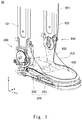
- Fig. 1 is a perspective view of an external appearance of an ankle joint regulation apparatus 10 according to an embodiment.
- the ankle joint regulation apparatus 10 is a regulation apparatus that regulates a movable range of an ankle joint 903 that connects a bone of a lower-thigh (i.e., a shinbone and a fibula) of a wearer with his/her anklebone.
- a lower-thigh i.e., a shinbone and a fibula
- the ankle joint regulation apparatus 10 is mainly composed of a lower-thigh frame 101 that is located on a side of a lower-thigh bone and supports a lower thigh 901, a sole frame 200 that is located on a side of the anklebone and supports a part from an ankle to a tip of a foot 902, and a joint mechanism 300 that supports these two frames so that they can swing within a swing range regulated along a movable direction of the ankle joint 903.
- the sole frame 200 includes a bottom plate 201 having a placement surface on which the wearer places his/her sole, and side plates 202 vertically disposed on sides of the bottom plate 201. More specifically, the joint mechanism 300 connects a lower end of the lower-thigh frame 101 with the outer-side side plate 202 in such a manner that they can swing.
- the sole frame 200 is attached to the foot 902 thorough an attachment belt or the like (not shown). For example, when the wearer wears a shoe-like cup sole, the sole frame 200 may be constructed so as to fix the cup sole.
- the joint mechanism 300 has such a structure that the joint mechanism 300 swings within a range that is narrower than a range within which the ankle joint 903 can be physically and naturally bent.
- the ankle joint regulating apparatus 10 further includes a lower-thigh frame 102 located on a side of the lower thigh 901 opposite to the side on which the lower-thigh frame 101 is located. That is, the lower-thigh frames 101 and 102 are attached so as to sandwich the lower thigh 901 therebetween and support the lower thigh 901. Note that the lower-thigh frames 101 and 102 are attached to the lower thigh 901 thorough an attachment belt or the like (not shown).
- the ankle joint regulating apparatus 10 includes a connecting mechanism 800 that connects the lower-thigh frame 102 with the inner-side side plate 202 in such a manner that they can swing.
- the connecting mechanism 800 does not include a structure for regulating the swing. That is, the movable range of the ankle joint 903 is not regulated by the connecting mechanism 800 located on the inner side thereof, but is instead regulated by the joint mechanism 300 located on the outer side thereof.
- the regulation range can be conveniently adjusted without detaching the ankle joint regulating apparatus 10 from the wearer.
- the ankle joint regulating apparatus 10 is a regulation apparatus for a right leg.
- a direction from an ankle toward a toe is defined as a positive direction on an x-axis
- a direction toward the inner side on a plane (i.e., a surface) of the bottom plate 201 is defined as a positive direction on a y-axis.
- a direction toward an upper body along the thigh is defined as a positive direction on a z-axis.
- the same coordinate system as that shown in Fig. 1 is shown in each of the subsequent drawings to clarify each direction.
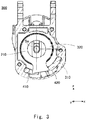
- Fig. 2 is a perspective view of an external appearance of the joint mechanism 300.
- Fig. 2 shows a state in which a cover 340 is attached to the joint mechanism 300.
- the cover 340 is attached to the joint mechanism 300 in order to prevent dust and the like from entering into the mechanism as shown in the figure.
- the joint mechanism 300 includes a holder 310 and stopper blocks 410 and 420 in addition to the cover 340.
- the stopper block 410 and the holder 310 are examples of the insertion-fitting member and the insertion-fitting receiving part, respectively.
- the holder 310 is fixed to the lower-thigh frame 101.
- the holder 310 is formed by, for example, carving it out of an aluminum block.
- the holder 310 may be connected to the lower-thigh frame 101 so that the holder 310 is allowed to slightly rotate around the x-axis with respect to the lower-thigh frame 101.
- a lever 350 has a function of pressing down the stopper block 410, which has been attached in the holder 310 by insertion, in a direction toward the holder to prevent the stopper block 410 from being removed.
- a lever 360 has a function of pressing down the stopper block 420, which has been attached in the holder 310 by insertion, in a direction toward the holder to prevent the stopper block 420 from being removed. Specific structures of the stopper blocks 410 and 420 and the levers 350 and 360 are described later.
- Fig. 3 is a cross section showing a configuration of a main part of the joint mechanism 300 when the holder 310 is cut on a plane parallel to the xz-plane. That is, Fig. 3 shows a state of an internal space of the holder 310.
- a swing shaft 320 is housed in the internal space of the holder 310. Note that the swing shaft 320 is an example of the regulation part.
- the swing shaft 320 is fixed to the side plates 202 of the sole frame 200 through a coupling member 210.
- the swing shaft 320 is pivotally supported on the holder 310 in such a manner that it can swing around a swing axis Sa. That is, when the wearer performs a dorsiflexion motion and a plantar-flexion motion by moving his/her ankle joint, the sole frame 200 follows the motions and hence the swing shaft 320 swings around the swing axis Sa with respect to the holder 310.
- the stopper block 410 is insertion-fitted into the holder 310 from the front thereof and regulates, regarding the swing range of the swing shaft 320, the swing angle of the plantar-flexion motion.
- the stopper block 420 is insertion-fitted into the holder 310 from the front thereof and regulates, regarding the swing range of the swing shaft 320, the swing angle of the dorsiflexion motion. Specific structures and specific motions are described later.
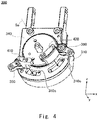
- Fig. 4 is a perspective view of an external appearance of the stopper blocks 410 and 420 showing a state in which they are insertion-fitted into the holder 310.
- Each of the stopper block 410 for plantar flexion and the stopper block 420 for dorsiflexion is replaceable (i.e., removable) for the holder 310.
- An insertion-fitting hole 310c, in which the stopper block 410 for plantar-flexion is inserted, and an insertion-fitting hole 310e, in which the stopper block 420 for dorsiflexion is inserted, are formed on the front side of the holder 310 and in the cover 340 covering the front of the holder 310.
- the insertion-fitting holes 310c and 310e are formed by hollowing out them so that their shapes conform to the circumferences of the stopper blocks 410 and 420, respectively, and have roughly elliptical shapes that extend along a circumference centered on the swing axis Sa.
- the stopper block 410 is inserted into the insertion-fitting hole 310c in a direction indicated by a dotted-line arrow. Note that the lever 350 is rotated to a position in which the lever 350 retreated from the insertion-fitting hole 310c before the insertion of the stopper block 410. Similarly, the stopper block 420 is inserted into the insertion-fitting hole 310e in a direction indicated by a dotted-line arrow. The lever 360 is rotated to a position in which the lever 360 is retreated from the insertion-fitting hole 310e before the insertion of the stopper block 420.
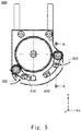
- Fig. 5 is a front view of the joint mechanism 300 for showing a lever operation.
- the lever 350 is rotated in a direction indicated by a dotted-line arrow, so that the lever 350 presses down the stopper block 410 in the positive direction on the y-axis.
- the lever 360 is rotated in a direction indicated by a dotted-line arrow, so that the lever 360 presses down the stopper block 420 in the positive direction on the y-axis.
- the stopper blocks 410 and 420 can be removed by performing the operations explained above with reference to Figs. 4 and 5 in a reversed order. Needless to say, only one of the stopper blocks may be attached or removed.
- the above-described levers 350 and 360 it is possible to firmly fix the stopper blocks 410 and 420 in the holder 310 and also possible to easily and swiftly replace them.
- Fig. 6 is a cross section taken along a line A-A in Fig. 5 , and shows a relation between the stopper block 420 attached in the holder 310 and the lever 360. Note that a relation between the stopper block 410 and the lever 350 is similar to the relation between the stopper block 420 and the lever 360, and therefore its explanation is omitted.
- the lever 360 is supported on the holder 310 in such a manner that the lever 360 can rotate around a lever shaft 361 that is screwed into a screw hole 310g formed in the holder 310.
- a plunger ball 366 is partially buried in the tip of the lever 360 and is urged (i.e., pressed) in the negative direction on the y-axis.
- the plunger ball 366 When the lever 360 is rotated and its tip is positioned above the stopper block 420, which has been insertion-fitted in the holder 310, the plunger ball 366 is engaged in a cone-shaped positioning hole 424 formed in the stopper block 420. Once the plunger ball 366 is engaged in the positioning hole 424, the lever 360 remains stopped and stabilized unless it is rotated by a relatively strong force.
- the above-described positioning mechanism using the positioning hole 424 and the plunger ball 366 stabilizes the position of the lever 360 and contributes to an improvement in feeling that a user has when he/she operates the lever.
- Fig. 7 is a perspective view of an external appearance of the stopper block 420.
- a structure of the stopper block 410 is similar to that of the stopper block 420 and therefore its explanation is omitted.
- the stopper block 420 has a shape which seems as if it was formed by cutting out a part of a cylindrical wall.
- the stopper block 420 is mainly composed of a projecting block part 421 and a knob part 425.
- the projecting block part 421 functions as a projecting part of the stopper block 420.
- the projecting block part 421 is a part of the stopper block 420 that is, when the stopper block 420 is insertion-fitted into the holder 310, disposed in the internal space of the holder 310 and collides with the swing shaft 320.
- the knob part 425 is a part that is disposed on the side of the cover 340.
- the stopper block 420 is formed by, for example, carving it out of an aluminum block.
- the projecting block part 421 and the knob part 425 may be carved out as one integral component, or may be separately produced and integrated into one component by an adhesive or the like.
- the knob part 425 is a part that is engaged in the above-described insertion-fitting hole 310e and also serves as a part that a user grasps when he/she replaces the stopper block 420.
- An inscribed mark 426 which is a mark indicating a property of the stopper block 420, is formed on a top surface 425a, i.e., an upper surface of the knob part 425.
- the inscribed mark 426 is provided so that a user can recognize, at a glance, whether the stopper block is for plantar-flexion or for dorsiflexion, and/or how long an effective length L k is (or how large a regulated swing angle is).
- the effective length L k and the swing angle are explained below.
- the above-described positioning hole 424 is formed on the top surface 425a.
- the projecting block part 421 extends, when the stopper block 420 is insertion-fitted in the holder 310, along a circumference centered on the swing axis Sa of the swing shaft 320. Further, the length of the projecting block part 421 is accurately adjusted to a predetermined effective length L k . That is, the effective length L K corresponds to the projecting length of the projecting part. Further, the end face of the tip of the projecting block part functions as an impact receiving surface 421a that comes into contact with the swing shaft 320.
- Fig. 8 is a schematic diagram schematically showing a reference state of the joint mechanism 300.
- the reference state means a state in which the wearer stands upright. In this state, the sole frame 200 is perpendicular to the lower-thigh frame 101.
- the swing shaft 320 includes an arm part 320a extending in a radial direction with respect to the swing axis Sa.
- the tip of the arm part 320a swings on the circumference on which the projecting block parts 411 and 421 are arranged within a range between the projecting block parts 411 and 421.
- the projecting block part 411 extends an effective length L k1 in the circumferential direction along which the tip of the arm part 320a swings.
- the projecting block part 421 extends an effective length L k2 in the circumferential direction along which the tip of the arm part 320a swings. That is, the swing range for plantar-flexion motions is regulated according to the effective length L k1 , i.e., the projecting length of the projecting block part 411 and the swing range for dorsiflexion motions is regulated according to the effective length L k2 , i.e., the projecting length of the projecting block part 421.
- Fig. 9 is a schematic diagram showing a state of a plantar-flexion rotation of the joint mechanism 300.
- An impact surface 320b which collides with an impact receiving surface 411a, i.e., an end face of the projecting block part 411, is formed on one side of the arm part 320a.
- the sole frame 200 swings in a direction indicated by a dotted-line arrow in the figure.
- the swing shaft 320 swings in a direction indicated by a bold-line arrow.
- the impact surface 320b collides with the impact receiving surface 411a. That is, the joint mechanism 300 regulates the swing range so that the swing shaft 320 can swing on the plantar-flexion side by ⁇ k degrees or smaller.
- the stopper block 410 for plantar-flexion is selected by a user from a set of a plurality of stopper blocks with projecting block parts 411 having different effective lengths L k1 according to the desired regulated swing range on the plantar-flexion side.
- a surface treatment has been performed on each of the impact surface 320b of the swing shaft 320 and the impact receiving surface 411a of the stopper block 410 so that the impact surface 320b collides with the impact receiving surface 411a in surface contact regardless of which of the stopper blocks having different effective lengths L k1 is inserted into the insertion-fitting hole 310c.
- the impact receiving surface 411a is processed (e.g., machined) into a flat surface along the radial direction centered on the swing axis Sa
- the impact surface 320b is also processed (e.g., machined) into a flat surface along the radial direction centered on the swing axis Sa. Since the impact surface 320b collides with the impact receiving surface 411a in surface contact irrespective of the desired regulated swing angle ⁇ k , it is possible to disperse an impact force that is caused at the time of a collision and thereby to reduce damage and wear of the stopper block 410.
- the set of stopper blocks may include a stopper block having an effective length L k1 by which the swing angle ⁇ k on the plantar-flexion side is regulated to 0 degrees.
- Fig. 10 is a schematic diagram showing a state of a dorsiflexion rotation of the joint mechanism 300.
- An impact surface 320c which collides with an impact receiving surface 421a, i.e., an end face of the projecting block part 421, is formed on the other side of the arm part 320a, i.e., a side of the arm part 320a opposite to the side on which the impact surface 320b is formed.
- the sole frame 200 swings in a direction indicated by a dotted-line arrow in the figure.
- the swing shaft 320 swings in a direction indicated by a bold-line arrow.
- the joint mechanism 300 regulates the swing range so that the swing shaft 320 can swing on the dorsiflexion side by ⁇ k degrees or smaller.
- the stopper block 420 for dorsiflexion is selected by a user from a set of a plurality of stopper blocks with projecting block parts 421 having different effective lengths L k2 according to the desired regulated swing range on the dorsiflexion side.
- a surface treatment has been performed on each of the impact surface 320c of the swing shaft 320 and the impact receiving surface 421a of the stopper block 420 so that the impact surface 320c collides with the impact receiving surface 421a in surface contact regardless of which of the stopper blocks having different effective lengths L k2 is inserted into the insertion-fitting hole 310e.
- the impact surface 320c is also processed (e.g., machined) into a flat surface along the radial direction centered on the swing axis Sa. Since the impact surface 320c collides with the impact receiving surface 421a in surface contact irrespective of the desired regulated swing angle ⁇ k , it is possible to disperse an impact force that is caused at the time of a collision and thereby to reduce damage and wear of the stopper block 420.
- the set of stopper blocks may include a stopper block having an effective length L k2 by which the swing angle ⁇ k on the dorsiflexion side is regulated to 0 degrees.
- the joint mechanism 300 can regulate each of the swing angle ⁇ k on the plantar-flexion side and the swing angle ⁇ k on the dorsiflexion side to a desired swing range independently of each other by selecting stopper blocks 410 and 420 having appropriate effective lengths L k1 and L k2 , respectively, and fixing the selected stopper blocks to the holder 310.
- the ankle joint regulation apparatus 10 since the swing range is regulated to a range narrower than a range in which a wearer can physically and naturally bend his/her foot as an ankle joint function, the impact surfaces 320b and 320c collide with the impact receiving surfaces 411a and 421a, respectively, with large forces.
- the ankle joint regulation apparatus 10 is configured so that the stopper blocks 410 and 420 are replaceable. Therefore, it is possible to accurately maintain the desired regulated swing range by replacing them with new ones according to their worn-out situation or the like. Further, the ankle joint regulation apparatus 10 is configured so that a wearer can easily insert or remove the stopper blocks 410 and 420 without detaching the ankle joint regulation apparatus 10 from the wearer. Therefore, the wearer can proceed with rehabilitation training without a hitch.
- an ankle joint regulation apparatus attached to an ankle joint in which relatively large impacts occur in both ends of the regulated swing range, is explained.
- use of the above-described joint mechanism is not limited to use for ankle joint regulation apparatuses. That is, the above-described joint mechanism can be used for joint regulation apparatuses used for any kinds of joints, provided that the joint mechanism supports a first member attached to a part of a body located on a side of one of bones and a second member attached to a part of the body located on a side of the other bone so that they can swing in a regulated swing range. Further, the relative rotation of the first and second members may be assisted by an actuator such as a motor.
- a joint regulation apparatus configured to regulate a movable range of a joint connecting a first bone part of a wearer with a second bone part of the wearer, including: a first member configured to be attached to a part of a body located on the first bone side; a second member configured to be attached to a part of the body located on the second bone side; and a joint mechanism configured to support the first and second members so that the first and second members can swing with respect to each other along a movable direction of the joint, in which the joint mechanism includes: a holder integrally provided with the first member; a regulation member including a projection part formed on a tip side, the regulation member being configured to be insertion-fitted into the holder in a replaceable manner; and a swing member configured to swing in an integrated manner with the second member, the swing member being further configured to come into contact with the projecting part of the regulation member at at least one of one end and the other end of a swinging motion, so that its
Landscapes
- Health & Medical Sciences (AREA)
- Life Sciences & Earth Sciences (AREA)
- Veterinary Medicine (AREA)
- Public Health (AREA)
- General Health & Medical Sciences (AREA)
- Animal Behavior & Ethology (AREA)
- Biomedical Technology (AREA)
- Vascular Medicine (AREA)
- Heart & Thoracic Surgery (AREA)
- Engineering & Computer Science (AREA)
- Orthopedic Medicine & Surgery (AREA)
- Nursing (AREA)
- Epidemiology (AREA)
- Pain & Pain Management (AREA)
- Physical Education & Sports Medicine (AREA)
- Rehabilitation Therapy (AREA)
- Rehabilitation Tools (AREA)
- Prostheses (AREA)
- Orthopedics, Nursing, And Contraception (AREA)
Claims (5)
- Stützapparat (10), mit:einem ersten Element (101), das konfiguriert ist, an einem Teil eines Körpers befestigt zu werden, der entlang eines ersten Knochenteils eines Trägers gelegen ist;einem zweiten Element (200), das konfiguriert ist, an einem Teil eines Körpers befestigt zu werden, der entlang eines zweiten Knochenteils des Trägers gelegen ist; undeinem Gelenkmechanismus (300), der konfiguriert ist, das erste und das zweite Element (101, 200) abzustützen, sodass das erste und das zweite Element (101, 200) in Bezug aufeinander um eine Drehachse drehen können, wobeider Stützapparat (10) ferner ein Passungs-Einsetzelement (410, 420) aufweist, das konfiguriert ist, um in den Gelenkmechanismus (300) auf eine solche Weise passungs-eingesetzt zu werden, dass das Passungs-Einsetzelement (410, 420) an dem Gelenkmechanismus (300) fixiert und davon entfernt werden kann,der Gelenkmechanismus (300)einen Passungs-Einsetzaufnahmeteil (310c, 310e), der einstückig mit dem ersten Element (101) vorgesehen ist, wobei der Passungs-Einsetzaufnahmeteil (310c, 310e) konfiguriert ist, dem Passungs-Einsetzelement (410, 420) zu ermöglichen, in den Gelenkmechanismus (300) passungs-eingesetzt zu werden; undeinen Einstellungsteil (320) aufweist, der einstückig mit dem zweiten Element (200) vorgesehen ist, wobei der Einstellungsteil (320) um die Drehachse in dem zweiten Element (200) angeordnet ist, undder Einstellungsteil (320), welcher auf eine einstückige Weise mit einer Drehung des zweiten Elements (200) um die Drehachse dreht, auf einer Trajektorie der Drehung des Einstellungsteils (320) mit einem Vorsprungsteil (411, 421) des Passungs-Einsetzelements (410, 420), das an dem Passungs-Einsetzaufnahmeteil (310c, 310e) fixiert ist, in Oberflächenkontakt gelangt, sodass ein Bereich der Drehung des zweiten Elements (200) eingestellt ist, wobei sich der Vorsprungsteil (411, 421) in Bezug auf die Drehachse in einer Umfangsrichtung erstreckt, dadurch gekennzeichnet, dassdas Passungs-Einsetzelement (410, 420), welches in den Passungs-Einsetzaufnahmeteil (310c, 310e) passungs-eingesetzt ist, gemäß einem gewünschten Einstelldrehbereich aus einem Satz einer Vielzahl von Passungs-Einsetzelementen (410, 420) ausgewählt ist, wobei die Vielzahl von Passungs-Einsetzelementen (410, 420) Vorsprungsteile (411, 421) aufweisen, die Vorsprungslängen haben, die voneinander verschieden sind, undder Gelenkmechanismus einen Schwenkarm (350, 360) aufweist, der konfiguriert ist, das Passungs-Einsetzelement (410, 420) in einer Richtung zu dem Passungs-Einsetzaufnahmeteil (310c, 310e) herunterzudrücken, nachdem das Passungs-Einsetzelement (410, 420) in den Passungs-Einsetzaufnahmeteil (310c, 310e) eingesetzt ist.
- Stützapparat (10) nach Anspruch 1, wobei das Passungs-Einsetzelement (410, 420) in der Lage ist, in einem Zustand, in welchem das erste und das zweite Element (101, 200) bereits an dem Träger befestigt sind, in den Passungs-Einsetzaufnahmeteil (310c, 310e) passungs-eingesetzt zu werden.
- Stützapparat (10) nach Anspruch 1 oder 2, wobei das Passungs-Einsetzelement (410, 420)
ein erstes Passungs-Einsetzelement (410), das einen ersten Vorsprungsteil (411) aufweist, der konfiguriert ist, mit dem Einstellungsteil (320) an einem Ende einer Drehbewegung davon in Kontakt zu gelangen; und
ein zweites Passungs-Einsetzelement (420) aufweist, das einen zweiten Vorsprungsteil (421) aufweist, der konfiguriert ist, mit dem Einstellungsteil (320) an dem anderen Ende der Drehbewegung davon in Kontakt zu gelangen. - Stützapparat (10) nach Anspruch 1, wobei der Gelenkmechanismus (360, 424) einen Positionierungsmechanismus (366) zum Stoppen des Schwenkarms (360) in einer vorbestimmten Position aufweist.
- Stützapparat (10) nach einem der Ansprüche 1 bis 4, wobei
eines des ersten und des zweiten Elements (101, 200) ein Unterschenkelrahmen (101) ist, der an einem Unterschenkel des Trägers befestigt ist,
das andere des ersten und des zweiten Elements (101, 200) eine Sohlenplatte (200) ist, auf welcher der Träger/die Trägerin seine/ihre Sohle platziert, und
der Drehbereich für den Gelenkmechanismus (300) bestimmt ist, sodass ein Bereich einer Plantarflexionsbewegung und einer Dorsiflexionsbewegung eines Sprunggelenks des Trägers eingestellt ist.
Applications Claiming Priority (1)
| Application Number | Priority Date | Filing Date | Title |
|---|---|---|---|
| JP2017078544A JP7067873B2 (ja) | 2017-04-11 | 2017-04-11 | 装具 |
Publications (2)
| Publication Number | Publication Date |
|---|---|
| EP3398570A1 EP3398570A1 (de) | 2018-11-07 |
| EP3398570B1 true EP3398570B1 (de) | 2020-05-13 |
Family
ID=61868425
Family Applications (1)
| Application Number | Title | Priority Date | Filing Date |
|---|---|---|---|
| EP18165395.7A Not-in-force EP3398570B1 (de) | 2017-04-11 | 2018-04-03 | Stütze und dafür verwendetes einsteckverbindungselement |
Country Status (4)
| Country | Link |
|---|---|
| US (1) | US20180289524A1 (de) |
| EP (1) | EP3398570B1 (de) |
| JP (1) | JP7067873B2 (de) |
| CN (1) | CN108685672B (de) |
Families Citing this family (2)
| Publication number | Priority date | Publication date | Assignee | Title |
|---|---|---|---|---|
| US12357487B2 (en) * | 2019-02-22 | 2025-07-15 | The Government Of The United States, As Represented By The Secretary Of The Army | Spring engagement and disengagement during gait cycle |
| US12178731B1 (en) * | 2021-06-15 | 2024-12-31 | Aspen Medical Products, Llc | Articulated ankle foot orthosis |
Family Cites Families (13)
| Publication number | Priority date | Publication date | Assignee | Title |
|---|---|---|---|---|
| JPH05137742A (ja) * | 1991-11-14 | 1993-06-01 | Takumi Hino | 人体補装具用継手および人体補装具 |
| US20030091382A1 (en) * | 2001-11-14 | 2003-05-15 | Julie Kowalsky | Non-restricting knee joint |
| JP3746451B2 (ja) * | 2001-12-25 | 2006-02-15 | 旭テクノグラス株式会社 | 線量読取装置 |
| US20040015112A1 (en) | 2002-02-14 | 2004-01-22 | Salutterback E. Gerald | Controlled motion ankle walker brace |
| US7044925B2 (en) * | 2002-12-30 | 2006-05-16 | Innovation Sports, Llc | Hinge system for regulating knee joint flexion and extension |
| JP2007054086A (ja) | 2005-08-22 | 2007-03-08 | Kochi Univ Of Technology | 動作補助用装具 |
| US20110009788A1 (en) * | 2009-07-13 | 2011-01-13 | Myomo, Inc. | Orthotic Device with Removably Attachable Actuator |
| AU2010275475B2 (en) * | 2009-07-24 | 2013-10-03 | Spinal Usa, Inc. | Bone plate screw-blocking systems and methods |
| ITMI20100784A1 (it) * | 2010-05-05 | 2011-11-06 | Consiglio Nazionale Ricerche | Snodo per articolazioni con elementi pseudoelastici |
| US9180038B2 (en) * | 2010-08-05 | 2015-11-10 | Ossur Hf | Walker having height adjustment and method for doing the same |
| US9788988B2 (en) * | 2010-09-08 | 2017-10-17 | Ossur Hf | Hinge for orthopedic devices |
| JP2016083100A (ja) * | 2014-10-24 | 2016-05-19 | トヨタ自動車株式会社 | 足装具用の関節ロック装置 |
| CN105640683A (zh) * | 2014-11-14 | 2016-06-08 | 财团法人玛利亚社会福利基金会 | 关节复健装置 |
-
2017
- 2017-04-11 JP JP2017078544A patent/JP7067873B2/ja active Active
-
2018
- 2018-03-27 US US15/936,702 patent/US20180289524A1/en not_active Abandoned
- 2018-04-03 EP EP18165395.7A patent/EP3398570B1/de not_active Not-in-force
- 2018-04-10 CN CN201810315536.0A patent/CN108685672B/zh not_active Expired - Fee Related
Non-Patent Citations (1)
| Title |
|---|
| None * |
Also Published As
| Publication number | Publication date |
|---|---|
| JP2018175317A (ja) | 2018-11-15 |
| CN108685672B (zh) | 2020-09-08 |
| CN108685672A (zh) | 2018-10-23 |
| JP7067873B2 (ja) | 2022-05-16 |
| US20180289524A1 (en) | 2018-10-11 |
| EP3398570A1 (de) | 2018-11-07 |
Similar Documents
| Publication | Publication Date | Title |
|---|---|---|
| EP3388043B1 (de) | Gelenkreguliereinrichtung | |
| JP5302343B2 (ja) | 下肢用支持シェル装置 | |
| KR101363834B1 (ko) | 족관절 보조장치 | |
| US11071639B2 (en) | Brace and insertion-fitting member used therefore | |
| EP3398570B1 (de) | Stütze und dafür verwendetes einsteckverbindungselement | |
| US20170224050A1 (en) | Customizable inserts for footwear | |
| CA2817927A1 (en) | Stabilizers for surgical tools | |
| CN113729846B (zh) | 膝关节截骨导板 | |
| CN110430841A (zh) | 一种包括缓冲元件的足假肢 | |
| EP3388044A2 (de) | Schalensohle, laufunterstützungsvorrichtung, index-elemente und schalensohlenbefestigungsverfahren | |
| JP6530269B2 (ja) | エルボークラッチ | |
| KR101769125B1 (ko) | 면접촉식 돌기부를 포함하는 인공무릎관절 | |
| WO2023140292A1 (ja) | 骨切り術支援治具、デジタルテンプレート及び長管骨矯正骨切り術 | |
| JP6307728B1 (ja) | 下肢装具用部品、下肢装具用靴、及び下肢装具 | |
| JP6575395B2 (ja) | 足装着装置 | |
| CN109496145A (zh) | 向使用者提供力辅助的外骨骼结构 | |
| JP2012165966A (ja) | 歩行支援装置 | |
| JP6957211B2 (ja) | 板バネアシスト装具 | |
| JP3841636B2 (ja) | 歩行用下肢装具およびその製造法 | |
| CN206304015U (zh) | 可拆卸鞋垫组件、可拆卸鞋垫及矫形鞋 | |
| JP2015217124A (ja) | 固定具及び下肢装具 | |
| JP2018140078A (ja) | 脚装具 | |
| ITUA20163575A1 (it) | Ortesi piede-caviglia articolata con asse di rotazione flottante | |
| Volpe | Using Gait Plates More Effectively in Children with In-Toe Gait. |
Legal Events
| Date | Code | Title | Description |
|---|---|---|---|
| PUAI | Public reference made under article 153(3) epc to a published international application that has entered the european phase |
Free format text: ORIGINAL CODE: 0009012 |
|
| STAA | Information on the status of an ep patent application or granted ep patent |
Free format text: STATUS: REQUEST FOR EXAMINATION WAS MADE |
|
| 17P | Request for examination filed |
Effective date: 20180403 |
|
| AK | Designated contracting states |
Kind code of ref document: A1 Designated state(s): AL AT BE BG CH CY CZ DE DK EE ES FI FR GB GR HR HU IE IS IT LI LT LU LV MC MK MT NL NO PL PT RO RS SE SI SK SM TR |
|
| AX | Request for extension of the european patent |
Extension state: BA ME |
|
| GRAP | Despatch of communication of intention to grant a patent |
Free format text: ORIGINAL CODE: EPIDOSNIGR1 |
|
| STAA | Information on the status of an ep patent application or granted ep patent |
Free format text: STATUS: GRANT OF PATENT IS INTENDED |
|
| INTG | Intention to grant announced |
Effective date: 20191209 |
|
| GRAS | Grant fee paid |
Free format text: ORIGINAL CODE: EPIDOSNIGR3 |
|
| GRAA | (expected) grant |
Free format text: ORIGINAL CODE: 0009210 |
|
| STAA | Information on the status of an ep patent application or granted ep patent |
Free format text: STATUS: THE PATENT HAS BEEN GRANTED |
|
| AK | Designated contracting states |
Kind code of ref document: B1 Designated state(s): AL AT BE BG CH CY CZ DE DK EE ES FI FR GB GR HR HU IE IS IT LI LT LU LV MC MK MT NL NO PL PT RO RS SE SI SK SM TR |
|
| REG | Reference to a national code |
Ref country code: GB Ref legal event code: FG4D |
|
| REG | Reference to a national code |
Ref country code: CH Ref legal event code: EP |
|
| REG | Reference to a national code |
Ref country code: DE Ref legal event code: R096 Ref document number: 602018004361 Country of ref document: DE |
|
| REG | Reference to a national code |
Ref country code: AT Ref legal event code: REF Ref document number: 1269278 Country of ref document: AT Kind code of ref document: T Effective date: 20200615 |
|
| REG | Reference to a national code |
Ref country code: LT Ref legal event code: MG4D |
|
| REG | Reference to a national code |
Ref country code: NL Ref legal event code: MP Effective date: 20200513 |
|
| PG25 | Lapsed in a contracting state [announced via postgrant information from national office to epo] |
Ref country code: SE Free format text: LAPSE BECAUSE OF FAILURE TO SUBMIT A TRANSLATION OF THE DESCRIPTION OR TO PAY THE FEE WITHIN THE PRESCRIBED TIME-LIMIT Effective date: 20200513 Ref country code: NO Free format text: LAPSE BECAUSE OF FAILURE TO SUBMIT A TRANSLATION OF THE DESCRIPTION OR TO PAY THE FEE WITHIN THE PRESCRIBED TIME-LIMIT Effective date: 20200813 Ref country code: FI Free format text: LAPSE BECAUSE OF FAILURE TO SUBMIT A TRANSLATION OF THE DESCRIPTION OR TO PAY THE FEE WITHIN THE PRESCRIBED TIME-LIMIT Effective date: 20200513 Ref country code: IS Free format text: LAPSE BECAUSE OF FAILURE TO SUBMIT A TRANSLATION OF THE DESCRIPTION OR TO PAY THE FEE WITHIN THE PRESCRIBED TIME-LIMIT Effective date: 20200913 Ref country code: PT Free format text: LAPSE BECAUSE OF FAILURE TO SUBMIT A TRANSLATION OF THE DESCRIPTION OR TO PAY THE FEE WITHIN THE PRESCRIBED TIME-LIMIT Effective date: 20200914 Ref country code: GR Free format text: LAPSE BECAUSE OF FAILURE TO SUBMIT A TRANSLATION OF THE DESCRIPTION OR TO PAY THE FEE WITHIN THE PRESCRIBED TIME-LIMIT Effective date: 20200814 Ref country code: LT Free format text: LAPSE BECAUSE OF FAILURE TO SUBMIT A TRANSLATION OF THE DESCRIPTION OR TO PAY THE FEE WITHIN THE PRESCRIBED TIME-LIMIT Effective date: 20200513 |
|
| PG25 | Lapsed in a contracting state [announced via postgrant information from national office to epo] |
Ref country code: LV Free format text: LAPSE BECAUSE OF FAILURE TO SUBMIT A TRANSLATION OF THE DESCRIPTION OR TO PAY THE FEE WITHIN THE PRESCRIBED TIME-LIMIT Effective date: 20200513 Ref country code: HR Free format text: LAPSE BECAUSE OF FAILURE TO SUBMIT A TRANSLATION OF THE DESCRIPTION OR TO PAY THE FEE WITHIN THE PRESCRIBED TIME-LIMIT Effective date: 20200513 Ref country code: RS Free format text: LAPSE BECAUSE OF FAILURE TO SUBMIT A TRANSLATION OF THE DESCRIPTION OR TO PAY THE FEE WITHIN THE PRESCRIBED TIME-LIMIT Effective date: 20200513 Ref country code: BG Free format text: LAPSE BECAUSE OF FAILURE TO SUBMIT A TRANSLATION OF THE DESCRIPTION OR TO PAY THE FEE WITHIN THE PRESCRIBED TIME-LIMIT Effective date: 20200813 |
|
| REG | Reference to a national code |
Ref country code: AT Ref legal event code: MK05 Ref document number: 1269278 Country of ref document: AT Kind code of ref document: T Effective date: 20200513 |
|
| PG25 | Lapsed in a contracting state [announced via postgrant information from national office to epo] |
Ref country code: NL Free format text: LAPSE BECAUSE OF FAILURE TO SUBMIT A TRANSLATION OF THE DESCRIPTION OR TO PAY THE FEE WITHIN THE PRESCRIBED TIME-LIMIT Effective date: 20200513 Ref country code: AL Free format text: LAPSE BECAUSE OF FAILURE TO SUBMIT A TRANSLATION OF THE DESCRIPTION OR TO PAY THE FEE WITHIN THE PRESCRIBED TIME-LIMIT Effective date: 20200513 |
|
| PG25 | Lapsed in a contracting state [announced via postgrant information from national office to epo] |
Ref country code: CZ Free format text: LAPSE BECAUSE OF FAILURE TO SUBMIT A TRANSLATION OF THE DESCRIPTION OR TO PAY THE FEE WITHIN THE PRESCRIBED TIME-LIMIT Effective date: 20200513 Ref country code: RO Free format text: LAPSE BECAUSE OF FAILURE TO SUBMIT A TRANSLATION OF THE DESCRIPTION OR TO PAY THE FEE WITHIN THE PRESCRIBED TIME-LIMIT Effective date: 20200513 Ref country code: SM Free format text: LAPSE BECAUSE OF FAILURE TO SUBMIT A TRANSLATION OF THE DESCRIPTION OR TO PAY THE FEE WITHIN THE PRESCRIBED TIME-LIMIT Effective date: 20200513 Ref country code: IT Free format text: LAPSE BECAUSE OF FAILURE TO SUBMIT A TRANSLATION OF THE DESCRIPTION OR TO PAY THE FEE WITHIN THE PRESCRIBED TIME-LIMIT Effective date: 20200513 Ref country code: DK Free format text: LAPSE BECAUSE OF FAILURE TO SUBMIT A TRANSLATION OF THE DESCRIPTION OR TO PAY THE FEE WITHIN THE PRESCRIBED TIME-LIMIT Effective date: 20200513 Ref country code: AT Free format text: LAPSE BECAUSE OF FAILURE TO SUBMIT A TRANSLATION OF THE DESCRIPTION OR TO PAY THE FEE WITHIN THE PRESCRIBED TIME-LIMIT Effective date: 20200513 Ref country code: EE Free format text: LAPSE BECAUSE OF FAILURE TO SUBMIT A TRANSLATION OF THE DESCRIPTION OR TO PAY THE FEE WITHIN THE PRESCRIBED TIME-LIMIT Effective date: 20200513 Ref country code: ES Free format text: LAPSE BECAUSE OF FAILURE TO SUBMIT A TRANSLATION OF THE DESCRIPTION OR TO PAY THE FEE WITHIN THE PRESCRIBED TIME-LIMIT Effective date: 20200513 |
|
| REG | Reference to a national code |
Ref country code: DE Ref legal event code: R097 Ref document number: 602018004361 Country of ref document: DE |
|
| PG25 | Lapsed in a contracting state [announced via postgrant information from national office to epo] |
Ref country code: SK Free format text: LAPSE BECAUSE OF FAILURE TO SUBMIT A TRANSLATION OF THE DESCRIPTION OR TO PAY THE FEE WITHIN THE PRESCRIBED TIME-LIMIT Effective date: 20200513 Ref country code: PL Free format text: LAPSE BECAUSE OF FAILURE TO SUBMIT A TRANSLATION OF THE DESCRIPTION OR TO PAY THE FEE WITHIN THE PRESCRIBED TIME-LIMIT Effective date: 20200513 |
|
| PLBE | No opposition filed within time limit |
Free format text: ORIGINAL CODE: 0009261 |
|
| STAA | Information on the status of an ep patent application or granted ep patent |
Free format text: STATUS: NO OPPOSITION FILED WITHIN TIME LIMIT |
|
| 26N | No opposition filed |
Effective date: 20210216 |
|
| PG25 | Lapsed in a contracting state [announced via postgrant information from national office to epo] |
Ref country code: SI Free format text: LAPSE BECAUSE OF FAILURE TO SUBMIT A TRANSLATION OF THE DESCRIPTION OR TO PAY THE FEE WITHIN THE PRESCRIBED TIME-LIMIT Effective date: 20200513 |
|
| REG | Reference to a national code |
Ref country code: DE Ref legal event code: R084 Ref document number: 602018004361 Country of ref document: DE |
|
| PG25 | Lapsed in a contracting state [announced via postgrant information from national office to epo] |
Ref country code: MC Free format text: LAPSE BECAUSE OF FAILURE TO SUBMIT A TRANSLATION OF THE DESCRIPTION OR TO PAY THE FEE WITHIN THE PRESCRIBED TIME-LIMIT Effective date: 20200513 |
|
| PG25 | Lapsed in a contracting state [announced via postgrant information from national office to epo] |
Ref country code: LU Free format text: LAPSE BECAUSE OF NON-PAYMENT OF DUE FEES Effective date: 20210403 |
|
| REG | Reference to a national code |
Ref country code: BE Ref legal event code: MM Effective date: 20210430 |
|
| PG25 | Lapsed in a contracting state [announced via postgrant information from national office to epo] |
Ref country code: LI Free format text: LAPSE BECAUSE OF NON-PAYMENT OF DUE FEES Effective date: 20210430 Ref country code: CH Free format text: LAPSE BECAUSE OF NON-PAYMENT OF DUE FEES Effective date: 20210430 |
|
| REG | Reference to a national code |
Ref country code: GB Ref legal event code: 746 Effective date: 20220107 |
|
| PG25 | Lapsed in a contracting state [announced via postgrant information from national office to epo] |
Ref country code: IE Free format text: LAPSE BECAUSE OF NON-PAYMENT OF DUE FEES Effective date: 20210403 |
|
| PG25 | Lapsed in a contracting state [announced via postgrant information from national office to epo] |
Ref country code: BE Free format text: LAPSE BECAUSE OF NON-PAYMENT OF DUE FEES Effective date: 20210430 |
|
| PGFP | Annual fee paid to national office [announced via postgrant information from national office to epo] |
Ref country code: FR Payment date: 20230309 Year of fee payment: 6 |
|
| PGFP | Annual fee paid to national office [announced via postgrant information from national office to epo] |
Ref country code: GB Payment date: 20230302 Year of fee payment: 6 |
|
| P01 | Opt-out of the competence of the unified patent court (upc) registered |
Effective date: 20230427 |
|
| PG25 | Lapsed in a contracting state [announced via postgrant information from national office to epo] |
Ref country code: CY Free format text: LAPSE BECAUSE OF FAILURE TO SUBMIT A TRANSLATION OF THE DESCRIPTION OR TO PAY THE FEE WITHIN THE PRESCRIBED TIME-LIMIT Effective date: 20200513 |
|
| PG25 | Lapsed in a contracting state [announced via postgrant information from national office to epo] |
Ref country code: HU Free format text: LAPSE BECAUSE OF FAILURE TO SUBMIT A TRANSLATION OF THE DESCRIPTION OR TO PAY THE FEE WITHIN THE PRESCRIBED TIME-LIMIT; INVALID AB INITIO Effective date: 20180403 |
|
| PGFP | Annual fee paid to national office [announced via postgrant information from national office to epo] |
Ref country code: DE Payment date: 20230228 Year of fee payment: 6 |
|
| PG25 | Lapsed in a contracting state [announced via postgrant information from national office to epo] |
Ref country code: MK Free format text: LAPSE BECAUSE OF FAILURE TO SUBMIT A TRANSLATION OF THE DESCRIPTION OR TO PAY THE FEE WITHIN THE PRESCRIBED TIME-LIMIT Effective date: 20200513 |
|
| PG25 | Lapsed in a contracting state [announced via postgrant information from national office to epo] |
Ref country code: TR Free format text: LAPSE BECAUSE OF FAILURE TO SUBMIT A TRANSLATION OF THE DESCRIPTION OR TO PAY THE FEE WITHIN THE PRESCRIBED TIME-LIMIT Effective date: 20200513 |
|
| PG25 | Lapsed in a contracting state [announced via postgrant information from national office to epo] |
Ref country code: MT Free format text: LAPSE BECAUSE OF FAILURE TO SUBMIT A TRANSLATION OF THE DESCRIPTION OR TO PAY THE FEE WITHIN THE PRESCRIBED TIME-LIMIT Effective date: 20200513 |
|
| REG | Reference to a national code |
Ref country code: DE Ref legal event code: R119 Ref document number: 602018004361 Country of ref document: DE |
|
| GBPC | Gb: european patent ceased through non-payment of renewal fee |
Effective date: 20240403 |
|
| PG25 | Lapsed in a contracting state [announced via postgrant information from national office to epo] |
Ref country code: DE Free format text: LAPSE BECAUSE OF NON-PAYMENT OF DUE FEES Effective date: 20241105 |
|
| PG25 | Lapsed in a contracting state [announced via postgrant information from national office to epo] |
Ref country code: GB Free format text: LAPSE BECAUSE OF NON-PAYMENT OF DUE FEES Effective date: 20240403 |
|
| PG25 | Lapsed in a contracting state [announced via postgrant information from national office to epo] |
Ref country code: FR Free format text: LAPSE BECAUSE OF NON-PAYMENT OF DUE FEES Effective date: 20240430 |
|
| PG25 | Lapsed in a contracting state [announced via postgrant information from national office to epo] |
Ref country code: GB Free format text: LAPSE BECAUSE OF NON-PAYMENT OF DUE FEES Effective date: 20240403 Ref country code: FR Free format text: LAPSE BECAUSE OF NON-PAYMENT OF DUE FEES Effective date: 20240430 Ref country code: DE Free format text: LAPSE BECAUSE OF NON-PAYMENT OF DUE FEES Effective date: 20241105 |