EP3398240B1 - Battery management system - Google Patents
Battery management system Download PDFInfo
- Publication number
- EP3398240B1 EP3398240B1 EP16834179.0A EP16834179A EP3398240B1 EP 3398240 B1 EP3398240 B1 EP 3398240B1 EP 16834179 A EP16834179 A EP 16834179A EP 3398240 B1 EP3398240 B1 EP 3398240B1
- Authority
- EP
- European Patent Office
- Prior art keywords
- battery
- controller
- temperature
- charging
- cells
- Prior art date
- Legal status (The legal status is an assumption and is not a legal conclusion. Google has not performed a legal analysis and makes no representation as to the accuracy of the status listed.)
- Active
Links
Images



Classifications
-
- H—ELECTRICITY
- H01—ELECTRIC ELEMENTS
- H01M—PROCESSES OR MEANS, e.g. BATTERIES, FOR THE DIRECT CONVERSION OF CHEMICAL ENERGY INTO ELECTRICAL ENERGY
- H01M10/00—Secondary cells; Manufacture thereof
- H01M10/42—Methods or arrangements for servicing or maintenance of secondary cells or secondary half-cells
- H01M10/425—Structural combination with electronic components, e.g. electronic circuits integrated to the outside of the casing
-
- H—ELECTRICITY
- H01—ELECTRIC ELEMENTS
- H01M—PROCESSES OR MEANS, e.g. BATTERIES, FOR THE DIRECT CONVERSION OF CHEMICAL ENERGY INTO ELECTRICAL ENERGY
- H01M10/00—Secondary cells; Manufacture thereof
- H01M10/42—Methods or arrangements for servicing or maintenance of secondary cells or secondary half-cells
- H01M10/44—Methods for charging or discharging
- H01M10/443—Methods for charging or discharging in response to temperature
-
- H—ELECTRICITY
- H01—ELECTRIC ELEMENTS
- H01M—PROCESSES OR MEANS, e.g. BATTERIES, FOR THE DIRECT CONVERSION OF CHEMICAL ENERGY INTO ELECTRICAL ENERGY
- H01M10/00—Secondary cells; Manufacture thereof
- H01M10/42—Methods or arrangements for servicing or maintenance of secondary cells or secondary half-cells
- H01M10/48—Accumulators combined with arrangements for measuring, testing or indicating the condition of cells, e.g. the level or density of the electrolyte
-
- H—ELECTRICITY
- H01—ELECTRIC ELEMENTS
- H01M—PROCESSES OR MEANS, e.g. BATTERIES, FOR THE DIRECT CONVERSION OF CHEMICAL ENERGY INTO ELECTRICAL ENERGY
- H01M10/00—Secondary cells; Manufacture thereof
- H01M10/42—Methods or arrangements for servicing or maintenance of secondary cells or secondary half-cells
- H01M10/48—Accumulators combined with arrangements for measuring, testing or indicating the condition of cells, e.g. the level or density of the electrolyte
- H01M10/486—Accumulators combined with arrangements for measuring, testing or indicating the condition of cells, e.g. the level or density of the electrolyte for measuring temperature
-
- H—ELECTRICITY
- H01—ELECTRIC ELEMENTS
- H01M—PROCESSES OR MEANS, e.g. BATTERIES, FOR THE DIRECT CONVERSION OF CHEMICAL ENERGY INTO ELECTRICAL ENERGY
- H01M50/00—Constructional details or processes of manufacture of the non-active parts of electrochemical cells other than fuel cells, e.g. hybrid cells
- H01M50/50—Current conducting connections for cells or batteries
- H01M50/569—Constructional details of current conducting connections for detecting conditions inside cells or batteries, e.g. details of voltage sensing terminals
-
- H—ELECTRICITY
- H02—GENERATION; CONVERSION OR DISTRIBUTION OF ELECTRIC POWER
- H02J—ELECTRIC POWER NETWORKS; CIRCUIT ARRANGEMENTS OR SYSTEMS FOR SUPPLYING OR DISTRIBUTING ELECTRIC POWER; SYSTEMS FOR STORING ELECTRIC ENERGY
- H02J7/00—Circuit arrangements for charging or discharging batteries or for supplying loads from batteries
- H02J7/50—Circuit arrangements for charging or discharging batteries or for supplying loads from batteries acting upon multiple batteries simultaneously or sequentially
- H02J7/52—Circuit arrangements for charging or discharging batteries or for supplying loads from batteries acting upon multiple batteries simultaneously or sequentially for charge balancing, e.g. equalisation of charge between batteries
-
- H—ELECTRICITY
- H02—GENERATION; CONVERSION OR DISTRIBUTION OF ELECTRIC POWER
- H02J—ELECTRIC POWER NETWORKS; CIRCUIT ARRANGEMENTS OR SYSTEMS FOR SUPPLYING OR DISTRIBUTING ELECTRIC POWER; SYSTEMS FOR STORING ELECTRIC ENERGY
- H02J7/00—Circuit arrangements for charging or discharging batteries or for supplying loads from batteries
- H02J7/50—Circuit arrangements for charging or discharging batteries or for supplying loads from batteries acting upon multiple batteries simultaneously or sequentially
- H02J7/52—Circuit arrangements for charging or discharging batteries or for supplying loads from batteries acting upon multiple batteries simultaneously or sequentially for charge balancing, e.g. equalisation of charge between batteries
- H02J7/54—Passive balancing, e.g. using resistors or parallel MOSFETs
-
- H—ELECTRICITY
- H02—GENERATION; CONVERSION OR DISTRIBUTION OF ELECTRIC POWER
- H02J—ELECTRIC POWER NETWORKS; CIRCUIT ARRANGEMENTS OR SYSTEMS FOR SUPPLYING OR DISTRIBUTING ELECTRIC POWER; SYSTEMS FOR STORING ELECTRIC ENERGY
- H02J7/00—Circuit arrangements for charging or discharging batteries or for supplying loads from batteries
- H02J7/60—Circuit arrangements for charging or discharging batteries or for supplying loads from batteries including safety or protection arrangements
- H02J7/61—Circuit arrangements for charging or discharging batteries or for supplying loads from batteries including safety or protection arrangements against overcharge
-
- H—ELECTRICITY
- H02—GENERATION; CONVERSION OR DISTRIBUTION OF ELECTRIC POWER
- H02J—ELECTRIC POWER NETWORKS; CIRCUIT ARRANGEMENTS OR SYSTEMS FOR SUPPLYING OR DISTRIBUTING ELECTRIC POWER; SYSTEMS FOR STORING ELECTRIC ENERGY
- H02J7/00—Circuit arrangements for charging or discharging batteries or for supplying loads from batteries
- H02J7/60—Circuit arrangements for charging or discharging batteries or for supplying loads from batteries including safety or protection arrangements
- H02J7/65—Circuit arrangements for charging or discharging batteries or for supplying loads from batteries including safety or protection arrangements against overtemperature
-
- H—ELECTRICITY
- H02—GENERATION; CONVERSION OR DISTRIBUTION OF ELECTRIC POWER
- H02J—ELECTRIC POWER NETWORKS; CIRCUIT ARRANGEMENTS OR SYSTEMS FOR SUPPLYING OR DISTRIBUTING ELECTRIC POWER; SYSTEMS FOR STORING ELECTRIC ENERGY
- H02J7/00—Circuit arrangements for charging or discharging batteries or for supplying loads from batteries
- H02J7/90—Regulation of charging or discharging current or voltage
- H02J7/971—Regulation of charging or discharging current or voltage the charge cycle being controlled or terminated in response to non-electric parameters
- H02J7/975—Regulation of charging or discharging current or voltage the charge cycle being controlled or terminated in response to non-electric parameters in response to temperature
-
- H—ELECTRICITY
- H02—GENERATION; CONVERSION OR DISTRIBUTION OF ELECTRIC POWER
- H02J—ELECTRIC POWER NETWORKS; CIRCUIT ARRANGEMENTS OR SYSTEMS FOR SUPPLYING OR DISTRIBUTING ELECTRIC POWER; SYSTEMS FOR STORING ELECTRIC ENERGY
- H02J7/00—Circuit arrangements for charging or discharging batteries or for supplying loads from batteries
- H02J7/90—Regulation of charging or discharging current or voltage
- H02J7/971—Regulation of charging or discharging current or voltage the charge cycle being controlled or terminated in response to non-electric parameters
- H02J7/975—Regulation of charging or discharging current or voltage the charge cycle being controlled or terminated in response to non-electric parameters in response to temperature
- H02J7/977—Regulation of charging or discharging current or voltage the charge cycle being controlled or terminated in response to non-electric parameters in response to temperature of the battery
-
- H—ELECTRICITY
- H01—ELECTRIC ELEMENTS
- H01M—PROCESSES OR MEANS, e.g. BATTERIES, FOR THE DIRECT CONVERSION OF CHEMICAL ENERGY INTO ELECTRICAL ENERGY
- H01M10/00—Secondary cells; Manufacture thereof
- H01M10/42—Methods or arrangements for servicing or maintenance of secondary cells or secondary half-cells
- H01M10/425—Structural combination with electronic components, e.g. electronic circuits integrated to the outside of the casing
- H01M2010/4271—Battery management systems including electronic circuits, e.g. control of current or voltage to keep battery in healthy state, cell balancing
-
- H—ELECTRICITY
- H01—ELECTRIC ELEMENTS
- H01M—PROCESSES OR MEANS, e.g. BATTERIES, FOR THE DIRECT CONVERSION OF CHEMICAL ENERGY INTO ELECTRICAL ENERGY
- H01M2220/00—Batteries for particular applications
- H01M2220/20—Batteries in motive systems, e.g. vehicle, ship, plane
-
- H—ELECTRICITY
- H02—GENERATION; CONVERSION OR DISTRIBUTION OF ELECTRIC POWER
- H02J—ELECTRIC POWER NETWORKS; CIRCUIT ARRANGEMENTS OR SYSTEMS FOR SUPPLYING OR DISTRIBUTING ELECTRIC POWER; SYSTEMS FOR STORING ELECTRIC ENERGY
- H02J7/00—Circuit arrangements for charging or discharging batteries or for supplying loads from batteries
- H02J7/60—Circuit arrangements for charging or discharging batteries or for supplying loads from batteries including safety or protection arrangements
- H02J7/62—Circuit arrangements for charging or discharging batteries or for supplying loads from batteries including safety or protection arrangements against overcurrent
-
- Y—GENERAL TAGGING OF NEW TECHNOLOGICAL DEVELOPMENTS; GENERAL TAGGING OF CROSS-SECTIONAL TECHNOLOGIES SPANNING OVER SEVERAL SECTIONS OF THE IPC; TECHNICAL SUBJECTS COVERED BY FORMER USPC CROSS-REFERENCE ART COLLECTIONS [XRACs] AND DIGESTS
- Y02—TECHNOLOGIES OR APPLICATIONS FOR MITIGATION OR ADAPTATION AGAINST CLIMATE CHANGE
- Y02E—REDUCTION OF GREENHOUSE GAS [GHG] EMISSIONS, RELATED TO ENERGY GENERATION, TRANSMISSION OR DISTRIBUTION
- Y02E60/00—Enabling technologies; Technologies with a potential or indirect contribution to GHG emissions mitigation
- Y02E60/10—Energy storage using batteries
-
- Y—GENERAL TAGGING OF NEW TECHNOLOGICAL DEVELOPMENTS; GENERAL TAGGING OF CROSS-SECTIONAL TECHNOLOGIES SPANNING OVER SEVERAL SECTIONS OF THE IPC; TECHNICAL SUBJECTS COVERED BY FORMER USPC CROSS-REFERENCE ART COLLECTIONS [XRACs] AND DIGESTS
- Y02—TECHNOLOGIES OR APPLICATIONS FOR MITIGATION OR ADAPTATION AGAINST CLIMATE CHANGE
- Y02T—CLIMATE CHANGE MITIGATION TECHNOLOGIES RELATED TO TRANSPORTATION
- Y02T10/00—Road transport of goods or passengers
- Y02T10/60—Other road transportation technologies with climate change mitigation effect
- Y02T10/70—Energy storage systems for electromobility, e.g. batteries
-
- Y—GENERAL TAGGING OF NEW TECHNOLOGICAL DEVELOPMENTS; GENERAL TAGGING OF CROSS-SECTIONAL TECHNOLOGIES SPANNING OVER SEVERAL SECTIONS OF THE IPC; TECHNICAL SUBJECTS COVERED BY FORMER USPC CROSS-REFERENCE ART COLLECTIONS [XRACs] AND DIGESTS
- Y02—TECHNOLOGIES OR APPLICATIONS FOR MITIGATION OR ADAPTATION AGAINST CLIMATE CHANGE
- Y02T—CLIMATE CHANGE MITIGATION TECHNOLOGIES RELATED TO TRANSPORTATION
- Y02T10/00—Road transport of goods or passengers
- Y02T10/60—Other road transportation technologies with climate change mitigation effect
- Y02T10/7072—Electromobility specific charging systems or methods for batteries, ultracapacitors, supercapacitors or double-layer capacitors
-
- Y—GENERAL TAGGING OF NEW TECHNOLOGICAL DEVELOPMENTS; GENERAL TAGGING OF CROSS-SECTIONAL TECHNOLOGIES SPANNING OVER SEVERAL SECTIONS OF THE IPC; TECHNICAL SUBJECTS COVERED BY FORMER USPC CROSS-REFERENCE ART COLLECTIONS [XRACs] AND DIGESTS
- Y02—TECHNOLOGIES OR APPLICATIONS FOR MITIGATION OR ADAPTATION AGAINST CLIMATE CHANGE
- Y02T—CLIMATE CHANGE MITIGATION TECHNOLOGIES RELATED TO TRANSPORTATION
- Y02T90/00—Enabling technologies or technologies with a potential or indirect contribution to GHG emissions mitigation
- Y02T90/10—Technologies relating to charging of electric vehicles
- Y02T90/12—Electric charging stations
-
- Y—GENERAL TAGGING OF NEW TECHNOLOGICAL DEVELOPMENTS; GENERAL TAGGING OF CROSS-SECTIONAL TECHNOLOGIES SPANNING OVER SEVERAL SECTIONS OF THE IPC; TECHNICAL SUBJECTS COVERED BY FORMER USPC CROSS-REFERENCE ART COLLECTIONS [XRACs] AND DIGESTS
- Y02—TECHNOLOGIES OR APPLICATIONS FOR MITIGATION OR ADAPTATION AGAINST CLIMATE CHANGE
- Y02T—CLIMATE CHANGE MITIGATION TECHNOLOGIES RELATED TO TRANSPORTATION
- Y02T90/00—Enabling technologies or technologies with a potential or indirect contribution to GHG emissions mitigation
- Y02T90/10—Technologies relating to charging of electric vehicles
- Y02T90/14—Plug-in electric vehicles
Definitions
- the present disclosure relates to battery management systems, for example battery management systems for rechargeable batteries.
- Rechargeable batteries are commonly used in many technologies, for example in electric or hybrid vehicles for use both on-highway and off-highway.
- rechargeable batteries are frequently used in automotive applications (on highway), offshore applications (off highway), in a warehouse environment (for example for use with mechanical handling equipment such as fork-lift trucks and autonomous guided vehicles, for example as described in WO 98/49075 - off highway) as well as in energy storage applications (both commercial and domestic - also off highway).
- BMS battery management system
- WO 2015/104263 which relates to a storage system employing the use of battery-powered autonomous guided vehicles, or robots, there is undesired robot standstill when the batteries are being charged. This reduces the operational cycle of the storage system as a whole, for example to typically 16 hours a day to accommodate 8 hours of charging time.
- WO 2015/104263 describes a battery comprising a receiving means enabling releasable connection to a corresponding charge station.
- WO 2015/104263 describes interchanging a first battery with a second battery, so that the robot can remain in use while the first battery is being charged by a charging station.
- EP 2 131 470 A2 SAMSUNG SDI CO LTD [KR] 9 December 2009 (2009-12-09); EP 2 866 294 A1 (SAMSUNG SDI CO LTD [KR]) 29 April 2015 (2015-04-29); US 2015/244192 A1 (DAUCHY JULIEN [FR] ET AL) 27 August 2015 (2015-08-27); WO 93/10589 A1 (SILENT POWER GMBH [DE]) 27 May 1993 (1993-05-27); US 2009/140694 A1 (ZENG JAMES JIN XIONG [US]) 4 June 2009 (2009-06-04); WO 2011/003513 A1 (LI TECH BATTERY GMBH [DE]; SCHAEFER TIM [DE]; GUTSCH ANDREAS [DE]) 13 January 2011 (2011-01-13); US 2014/222359 A1 (KO JONG-KYUNG [KR] ET AL) 7 August 2014 (2014-08-07); EP 2 6
- a rechargeable battery pack 100 comprises a BMS 101 and a rechargeable battery 105.
- the BMS 101 comprises a controller 103 and a temperature sensor 105 that provides a temperature signal based on the temperature of the rechargeable battery 103.
- the rechargeable battery pack 100 can be coupled to a power source such as a charging station to charge the rechargeable battery 105 via the BMS 101.
- the controller 103 of the BMS is configured to control a charging current provided by the power source to the rechargeable battery 105 based on the temperature signal provided by the temperature sensor 107.
- the charging current is tapered down as a function of increasing temperature.
- the rechargeable battery 105 has a nominal operating range, such as between 10-40 °C. If the temperature sensor 107 provides a temperature signal indicating that the temperature of the rechargeable battery 105 reaches a threshold temperature, for example 42 °C, the controller 103 throttles the current supplied to the rechargeable battery 105 in an effort to stop the temperature of the battery 105 from continuing to rise. If the temperature signal indicates that the temperature of the rechargeable battery 105 is higher, for example 43 or 44 °C, the controller 103 may throttle the current further, so that less current is supplied to the battery 105 than at, for example, 42 °C.
- a threshold temperature for example 42 °C
- the controller may throttle the current altogether so that no current is supplied to the rechargeable battery 105, in an effort to ensure the temperature of the rechargeable battery 105 does not exceed the second threshold temperature and thereby prevent damage being caused to the rechargeable battery 105.
- a second threshold temperature for example 45 °C
- the battery 105 can be charged more quickly without damaging the battery 105. Because the temperature of the rechargeable battery 105 is used, performance of the battery 105 can be maintained even if the field of application is in particularly hot or cold environments, such as for vehicles designed for use in the Antarctic or in the desert.
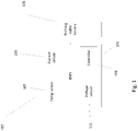
- Fig. 1 comprises a battery pack 100 comprising a BMS 101 coupled to a rechargeable battery 105.
- the rechargeable battery comprises at least one LiFePO 4 cell.
- the BMS 101 comprises a controller 103, a current sensor 109, a temperature sensor 107 and a voltage sensor 111 all coupled in series to the controller 103.
- the controller 103, voltage sensor 111 and current sensor 109 in the example are arranged on a printed circuit board.
- the temperature sensor 107 is coupled to the positive end of the stack of cells. Due to the peltier effect, the positive end of the stack will become hotter than the negative end in use, and so the temperature sensor is coupled to the hottest cell of the stack.
- the controller 103 further comprises a data store comprising a stored relationship.
- the stored relationship comprises a lookup table providing set current values as a function of temperature.
- the BMS 101 is couplable to a source of charging current, for example a charging point 300.
- the controller 103 is configured to send a request to the charging point 300 for a charging current to supply the battery 105.
- the temperature sensor 107 is configured to provide a temperature signal based on a temperature of the rechargeable battery 105.
- the current sensor 109 monitors the charging current to the rechargeable battery 105 and provides a current signal to the controller 103.
- the controller 103 is configured to control (for example, throttle) the charging current for charging the rechargeable battery 105 based on the temperature signal.
- the controller comprises a current restrictor for controlling the charging current to the battery 105, for example a transistor such as a field effect transistor.
- the controller 103 is configured to control (or throttle) the flow of charging current to the battery 105 during charging of the battery 105.
- the controller 103 is configured to control the charging current based on the temperature signal and the current signal, although in other examples the controller 103 may control the charging current based on just the temperature signal. Tapering of the current based on temperature is according to the stored relationship, for example a lookup table, and the controller 103 is configured to control the charging current based on the stored relationship.
- the battery pack 100 is coupled to a charging point 300.
- charging of the battery 105 begins.
- the controller 103 of the BMS 101 of the battery pack 100 may send the current request in response to making a determination about whether charging of the battery 105 is required based on at least one parameter of the battery 105, for example based on the voltage of the battery 105.
- the temperature sensor 107 monitors the temperature of the battery 105, and the current sensor 109 monitors the charging current to the battery 105.
- the temperature sensor 107 sends a temperature signal to the controller 103 and the current sensor 109 sends a current signal to the controller 103.
- the controller 103 tapers down (or throttles) the charging current as a function of increasing temperature.
- the first threshold temperature may be 42°C.
- the tapering may be according to a linear relationship between current and temperature, for example.
- the controller 103 in response to the temperature signal indicating that the temperature exceeds a second threshold temperature, controls or throttles the charging current so that no charging current is supplied to the battery 105.
- the second threshold temperature may be 45°C.
- the controller 103 in response to the temperature signal indicating that the temperature is below a third threshold, is configured to taper the charging current down as a function of decreasing temperature.
- the third threshold temperature may be 5°C.
- the tapering may be according to a linear relationship between current and temperature, for example.
- the controller 103 may be configured to control or throttle the charging current so that no charging current is supplied to the battery 105.
- the fourth threshold temperature may be 0°C.
- the controller 103 may be configured to control the flow of charging current to the battery 105 during charging of the battery 105 so that the temperature of the battery is within a selected range.
- the selected range may have end-points that correspond to the second and fourth threshold temperatures described above.
- a controller 103 controls a charging current for charging a rechargeable battery 105 based on a temperature signal received from a temperature sensor 107.
- the rechargeable battery 105 may comprise a plurality of cells 106, and in the second mode the controller 103 is configured to balance the cells 106 of the rechargeable battery 105 based on an indicated level of charge of each respective cell 106, for example based on a voltage signal provided by a voltage sensor 111.
- a rechargeable battery 105 comprising a plurality of cells 106 can be rapidly charged during the first mode, and then once the rechargeable battery 105 is charged to a certain level, for example a certain voltage level as indicated by the voltage sensor 111, the BMS 101 can then balance the cells 106 based on their respective levels of charge, for example so that all of the cells 106 are charged to the same level.
- a certain level for example a certain voltage level as indicated by the voltage sensor 111
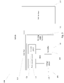
- the actual example actually shown in Fig. 2 shows a battery pack 100 similar to the battery pack shown in Fig. 1 .
- the battery pack 100 shown in Fig. 2 comprises a BMS 101 coupled to a rechargeable battery 105.
- the BMS 101 comprises a controller 103, a voltage sensor 111 and a current sensor 109 arranged in series and coupled to the battery 105, and a temperature sensor 107 coupled to the battery 105 and the controller 103.
- the rechargeable battery 105 comprises three cells 106 arranged in a stack connected in series. Each cell 106 of the battery 105 has a corresponding resistor 104 arranged in parallel with that cell 106. A switch 102 is coupled in series between each resistor 104 and cell 106.
- the controller 103, voltage sensor 111, current sensor 109 and temperature sensor 107 operate in much the same way as those described above in relation to Fig. 1 .
- the controller 103 is configured to send a request to a charging point for a charging current to supply the battery 105.
- the temperature sensor 107 is configured to provide a temperature signal based on a temperature of the rechargeable battery 105.
- the voltage sensor 111 is operable to provide a voltage signal to act as a charge indicator to provide the indication of the level of charge of the cells 106 of the battery 105.
- the controller is configured to operate in at least two modes.
- the controller 103 controls a charging current for charging the battery 105 based on the temperature signal from the temperature sensor 107, for example in a manner described above in relation to Fig. 1 .
- the controller 103 is configured to balance the cells 106 of the battery 105 based on the indicated level of charge of each respective cell 106.
- the controller 103 is configured to control the charging current to each cell 106 of the battery 105. To do this, the controller 103 is operable to control each switch 102 to control the flow of current to each resistor 104 and hence the flow of charging current to each cell 106.
- the controller 103 is configured to balance the cells 106 of the battery 105 in the second mode during charging of the battery 105 and in a third mode during discharging of the battery 105.
- the controller 103 may be configured to control the current drawn from each cell 106 during the third mode during discharge.
- the battery pack 100 is coupled to a charging point.
- charging of the battery 105 begins.
- the temperature sensor 107 monitors the temperature of the battery 105, and sends a temperature signal to the controller 103.
- the current sensor 109 monitors the charging current to the battery 105 and sends a current signal to the controller 103.
- the controller in response to the temperature signal indicating that the temperature exceeds a first threshold temperature, the controller tapers (or throttles) the charging current down as a function of increasing temperature.
- the BMS 101 operates in the second mode when a selected threshold is reached.
- the BMS 101 operates in the second mode when a selected voltage threshold is reached, as indicated by a voltage signal provided by the voltage sensor 111.
- the voltage signal may represent a level of charge of the battery 105, as described above, the BMS 101 may operate in the second mode once the level of charge of the battery 105 has reached a certain level.
- the voltage threshold may be, for example, 3.1 V, for example, 3.3 V, for example 3.6 V.
- the controller 103 balances the cells 106 based on an indicated level of charge of each respective cell 106, for example based on the voltage of each respective cell 106.
- the controller 103 controls the corresponding switch 102 for each respective cell 106.
- the controller 103 controls the amount of current flowing through each corresponding resistor 104. Because each resistor 104 is arranged in parallel with each cell 106, controlling the current to each resistor 104 also controls the current to each cell 106.
- the controller 103 may operate in the second mode during charging in response to the charging current being supplied to the battery 105 exceeding a selected charging current threshold, for example 0.5 A.
- the controller 103 may operate in the second mode during charging in response to the charging voltage being supplied to the battery 105 exceeding a selected charging voltage threshold, for example 3.0V.
- the controller 103 may rank each of the cells 106 of the battery 105 in voltage order, and control the charging current to each of the cells 106 of the battery 105 based on the ranking.
- the controller 103 may also control the charging current to each of the cells 106 based on an offset between the voltage of the highest and lowest cells 106.
- the controller may control the charging current to each of a selected number of cells 106, for example the top cell 106, the top 2 cells 106, the top 3 cells 106 or the top 4 cells 106, until the offset between each of those cells 106 with the bottom cell 106 reaches a threshold value, such as 0.002V.
- the controller 103 may operate in the third mode.
- the controller 103 may only balance the cells 106 of the battery 105 during discharge in response to the voltage of a cell 106 of the battery 105 meeting and/or exceeding a selected voltage threshold, for example greater than or equal to 3.6 V, greater than or equal to 3.9 V, greater than or equal to 4.2 V.
- a selected voltage threshold for example greater than or equal to 3.6 V, greater than or equal to 3.9 V, greater than or equal to 4.2 V.
- the controller 103 may function in a similar way to the BMS of Fig. 1 .
- the controller 103 may be configured to control the flow of charging current to the battery 105 during charging of the battery 105 so that the temperature of the battery is within a selected range.
- the selected range may correspond to the second and fourth threshold temperatures.
- the battery 105 comprises two stacks of cells 106 arranged in series, and two temperature sensors 107, each temperature sensor 107 arranged to provide a temperature signal based on a temperature of each stack of cells 106.
- the controller 103 may be configured to control the charging current to the battery 105 based on the respective highest or lowest monitored temperature of the two temperature sensors 107.
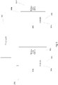
- the BMS shown in Fig. 3 comprises a controller 103 configured to communicate with a vehicle drive 201, for example via an Interface 113.
- the BMS 101 further comprises a charging detector, for example a current sensor 109, which detects whether a rechargeable battery 105 is being charged.
- the controller 103 is configured to send a signal to the vehicle drive 201 via the interface 113 to inhibit operation of the vehicle drive 201 in response to the charging detector detecting that the rechargeable battery 105 is being charged.
- Fig. 3 shows a vehicle 200 comprising a battery pack 100, such as the battery pack 100 shown in Fig. 1 .
- the battery pack 100 comprises an interface 113.
- the battery pack 100 is coupled to a vehicle drive 201 via the interface 113.
- the vehicle drive 201 may be an electric motor, for example.
- FIG. 3 shows a battery pack 100 comprising a BMS 101 coupled to the interface 113 and a rechargeable battery 105.
- the interface 113 may be a controller area network (CAN) interface.
- the BMS 101 comprises a controller 103, a charging detector, which in the example shown is a current sensor 109, a temperature sensor 107 and a voltage sensor 111 all coupled to the controller 103.
- the controller 103 is configured to communicate with the vehicle drive 201 via the interface 113.
- the current sensor 109 is configured to detect whether the battery 105 is being charged.
- the controller 103 is configured to send a signal to inhibit operation of the vehicle drive 201 in response to the current sensor 109 detecting that the battery 105 is being charged.
- the controller 103 may be configured to communicate over a network, for example a CAN bus.
- the controller 103 may send the signal to inhibit operation of the vehicle drive 201 over the CAN bus.
- the controller 103 may broadcast a charging advert over the CAN bus.
- the battery pack 100 is coupled to a charging point.
- charging of the battery 105 begins.
- the current sensor 109 monitors the charging current to the battery 105.
- the current sensor 109 sends a current signal to the controller 103.
- the controller 103 sends a signal to via the interface 113 to inhibit operation of the vehicle drive 201.
- the BMS 101 comprises an optional voltage sensor 111 which acts as a charge indicator.
- the voltage sensor 111 is configured to provide an indication of the level of charge of the battery 105 to the controller.
- the voltage sensor 111 sends a voltage signal to the controller 103.
- the controller 103 In response to the voltage sensor 111 sending a voltage signal to the controller 103 indicating that the level of charge is below a charge threshold, the controller 103 is configured to send a charging advert, for example over a network such as a CAN bus.
- the charging advert may be a repeating advert or a single message. It may be broadcast over a network or sent to specific devices coupled to the controller 103. Where the charging advert is a repeating advert, in response to the voltage signal indicating that the level of charge is above a charge threshold, the controller 103 may no longer sends a charging advert over the network.
- the charge threshold may be, for example, 3.6 V.
- the controller 103 may send a repeating current request message to a charging point over the network.
- the controller 103 may send a signal to inhibit operation of the vehicle drive 201.
- the controller 103 may be configured to repeatedly poll the network for a response to the broadcasted current request in a time interval following the broadcasted current request.
- the controller 103 may be configured to send a signal to the vehicle drive 201 overriding the signal to inhibit operation of the vehicle drive 201.
- the controller 103 is configured to inhibit operation of the vehicle drive by sending a repeating charging advert to the vehicle drive 201 over the network.
- a BMS 101 comprising a controller 103 and a voltage sensor 111 that can disconnect the charging current to a battery 105 in response to a measured battery voltage exceeding a voltage threshold.
- the BMS 101 may be configured to disconnect the charging current in response to a voltage spike, for example due to a short-circuit or arcing. In this way, the BMS 101 may act in a manner similar to a fuse.
- the embodiments shown in the Figures are merely exemplary, and include features which may be generalised, removed or replaced as described herein and as set out in the claims.
- the actual example actually shown in Fig. 4 shows a battery pack 100, again similar to the battery pack of Fig. 1 .
- the battery pack 100 shown in Fig. 4 comprises a rechargeable battery 105 coupled to a BMS 101.
- the BMS 101 comprises a controller 103 and a voltage sensor 111.
- the voltage sensor 111 is configured to measure a voltage of the battery 105 and send a voltage signal to the controller 103.
- the controller 103 is configured to receive a voltage signal from the voltage sensor 111.
- the controller 103 is configured to disconnect a charging current to the battery 105 in response to the voltage signal (indicative of the measured battery voltage) exceeding a voltage threshold.
- the battery pack 100 is coupled to a charging point.
- the controller 103 sending a request to the charging point, charging of the battery 105 begins.
- the voltage sensor 111 monitors the voltage of the battery 105 at all times, but in some examples may only monitor the voltage of the battery 105 during charging of the battery 105.
- the voltage sensor 111 sends a voltage signal to the controller 103.
- the controller 103 may control when the voltage sensor 111 is monitoring the voltage of the battery 105.
- the controller 103 In response to the controller 103 receiving a voltage signal exceeding a voltage threshold, the controller 103 disconnects the charging current to the battery 105.
- the BMS 101 may comprise a field effect transistor, and the controller 103 may control the field effect transistor to disconnect or throttle the charging current.
- the voltage threshold is selected so that it is larger than a nominal operating voltage range of the battery 105.
- the voltage threshold may be greater than 4 V, greater than 8 V, greater than 10 V, greater than 15 V, greater than 20 V.
- the voltage threshold may be selected to correspond to a voltage spike caused by arcing, for example due to arcing between charging contacts on the battery pack 100 and a charging point.
- the battery 105 comprises a plurality of cells 106.
- Each cell 106 may comprise a voltage sensor 111 that sends a respective voltage signal to the controller 103.
- the controller 103 may be configured to disconnect the charging current to the battery 105 in response to at least one of the voltage signals exceeding the threshold value.
- a charging point 300 for a rechargeable battery 105 that can control charging of the battery 105 based on a parameter of the battery 105, such as temperature or voltage.
- the charging point 300 comprises a charging port 305 for electrically coupling with the rechargeable battery 105 of the rechargeable battery pack 100.
- the charging point 300 also comprises a controller 303, and an interface 313 for receiving at least one parameter of the rechargeable battery 105.
- the at least one parameter may comprise at least one of a temperature of the battery 105, for example as measured using a temperature sensor 107, and a voltage of the battery 105, for example as measured using a voltage sensor 111.
- the controller 303 of the charging point 303 is configured to control the charging current to the battery 105 during charging of the battery 105 based on the at least one parameter.
- FIG. 5 shows a charging point 300 for charging a rechargeable battery pack 100, such as the rechargeable battery pack 100 of Figs. 1 , 2 or 4 .
- the charging point 300 shown in Fig. 5 comprises a charging port 305 coupled to a controller 303 via an interface 313.
- the battery pack 100 comprises a BMS 101 coupled to a rechargeable battery 105.
- the BMS 101 comprises a controller 103, an optional current sensor 109, a temperature sensor 107 and a voltage sensor 111 all coupled to the controller 103.
- the BMS 101 may comprise only one of, or any combination of, the current sensor 109, the temperature sensor 107 and the voltage sensor 111.
- the controller 103 of the battery pack 100 is configured to send a request to the charging point 300 for a charging current to supply the battery 105.
- the temperature sensor 107 is configured to provide a temperature signal based on a temperature of the rechargeable battery 105.
- the current sensor 109 monitors the charging current to the rechargeable battery 105 and is configured to provide a current signal to the controller 103.
- the voltage sensor 111 monitors the voltage of the rechargeable battery 105 and is configured to provide a voltage signal to the controller 103.
- the charging port 305 is configured to electrically couple with the rechargeable battery 105 of the rechargeable battery pack 100.
- the controller 303 is configured to receive at least one parameter of the rechargeable battery 105 of the battery pack 100 via the interface 313.
- the at least one parameter comprises at least one of a temperature of the battery received as a temperature signal from the temperature sensor 107 and a voltage of the battery 105 received as a voltage signal from the voltage sensor 111, via the controller 103 of the BMS 101.
- the controller 303 of the charging point 300 is configured to control the charging current to the battery 105 during charging of the battery 105 based on the at least one parameter.
- the controller 303 is configured to communicate over a network, for example a CAN bus, via the interface 313 with the controller 103 of the BMS 101 of the battery pack 100.
- the controller 303 is configured to communicate with a rechargeable battery pack 100 via the interface 313 and the charging port 305.
- the controller 303 is configured to control the charging current to the battery 105 based on the at least one other parameter being received in a message over the network.
- the rechargeable battery pack 100 is coupled to the charging point 300 via the charging port 305.
- Charging can begin in a number of different ways.
- the controller 103 of the BMS 101 of the battery pack 100 may send a current request to the charging point 300.
- the controller 303 of the charging point 300 may begin charging the battery 105 of the battery pack 100.
- the controller 103 of the BMS 101 of the battery pack 100 may send the current request in response to making a determination about whether charging of the battery 105 is required based on the at least one parameter.
- the controller 303 may send a signal or message to the controller 103 of the BMS 101 of the battery pack 100, requesting information regarding the at least one other parameter.
- the controller 103 of the BMS 101 of the battery pack 100 may send a signal or message comprising information relating to the at least one parameter to the controller 303 of the charging point 300.
- the controller 303 of the charging point 300 may make a determination about whether to start charging of the battery 105 of the battery pack 100.
- the controller 303 of the charging point 300 controls the charging current to the battery 105 during charging of the battery 105 based on the at least one parameter. For example, in response to a voltage signal indicating that the level of charge of the battery 105 has reached a charge threshold, the controller 303 may taper or cut off the charging current supplied to the battery 105.
- the charge threshold may be, for example, 3.6 V.
- the controller 103 is configured to control (or throttle) the charging current for charging the rechargeable battery 105 based on the temperature signal.
- the controller comprises a current restrictor for controlling the charging current to the battery 105, for example a field effect transistor.
- the at least one parameter may comprise an instruction to send current.
- the charging point 300 may be configured to commence the charging current to the battery 105 and therefore start charging upon receiving a first message via the interface 313, and to inhibit the charging current to the battery 105, and therefore stop charging, upon receiving a second message via the interface 313.
- the controller 303 of the charging point 300 may be configured to repeatedly send an advertisement message via the interface 313.
- the charging point 300 may be configured to control the charging current to the battery 105 upon acknowledgement of receipt of the advertisement message.
- the controller 303 of the charging point 300 is configured to communicate with a rechargeable battery pack 100 via the interface 313 and the charging port 305. In other examples the controller 303 of the charging point 300 is configured to communicate with a rechargeable battery pack 100 via the interface 313 but not via the charging port 305.
- the charging point 300 may be configured to communicate with a rechargeable battery pack 100 via a network port, such as a CAN port that is operable to couple with the rechargeable battery pack 100.
- FIG. 6 Other embodiments of the claims, for example as shown in Fig. 6 , relate to a BMS 101 that can be used in charging a plurality of rechargeable battery packs 100, for example so that the battery packs 100 are charged to the same level.
- Each battery pack 100 comprises a rechargeable battery 105 and a BMS 101 comprising a controller 103.
- Each of the battery packs 100 are coupled to a charging point 300, either in series or in parallel.
- the controller 103 of one battery pack 100 is configured to communicate with the controller 103 of another battery pack 100, and upon communicating with each other each battery pack 100 is configured to designate itself as either a "master" or "slave".
- the controller 103 of the master battery pack 100 is configured to receive information regarding parameters regarding the battery 105 of the slave battery pack 100 and control a charging current from the charging point 300 to the batteries 105, of either the slave or both the master and the slave battery packs 100, based on the information received from the slave battery pack 100.
- FIG. 6 shows an example BMS 101a for charging a plurality of batteries 105a, 105b.
- Fig. 6 shows two battery packs 100a and 100b.
- the two battery packs 100a, 100b shown in Fig. 6 are coupled to each other and to a charging point 300, for example the charging point of Fig. 5 described above.
- the first battery pack 100a comprises a BMS 101a coupled to a rechargeable battery 105a.
- the BMS 101a comprises a controller 103a.
- the second battery pack 100b also comprises a BMS 101b coupled to a rechargeable battery 105b.
- the BMS 101b also comprises a controller 103b.
- the controller 103a of the first BMS 101a is configured to communicate with the controller 103b of the second BMS 101b, for example via an optional interface (not shown).
- the controller 103a of the first BMS 101a is configured to designate itself as a master controller 103a and designate the other controller as a slave controller 103b.
- the master controller 103a is configured to receive information regarding parameters of the second battery 105b of the plurality of batteries from the slave controller 103b.
- the parameters of the battery 105 may include at least one of: pack temperature, pack voltage, charging current flow to pack, number of cells per pack, charging current flow to each cell and voltage of each cell.
- the master controller 103a is configured to control a charging current received from the barging point 300 to the plurality of batteries 105a, 105b based on the received information and based on information regarding parameters of the first battery 105a.
- the battery packs 100a, 100b are coupled to the charging point 300.
- the master controller 103a may make a determination when the plurality of batteries 105a, 105b need charging based on the received information regarding the first battery 105a, the second battery 105b or a combination of both.
- charging of the batteries 105a, 105b begins.
- the master controller 103a controls the current supplied to both batteries 105a, 105b based on the received information.
- the master controller 103a may control current supplied to the batteries 105a, 105b based on the highest or lowest temperature of the plurality of batteries.
- the master controller 103a may control the current supplied to the batteries 105a, 105b in a number of different ways. For example, in some examples the master controller 103a may directly control the flow of current from the charging point 300 to the second battery pack 100b. In other examples, the master controller 103a may be configured to send instructions to the slave controller 103b. The master controller 103a may send a signal to the slave controller 103b telling the slave controller 103b what current to request from the charging point 300.
- the master controller 103a may control the current supplied to the batteries 105a, 105b so that both batteries 105a, 105b are charged to the same level. This may be useful when one battery charges more quickly than the other.
- the master controller 103a may be configured to supply current to both batteries 105a, 105b at an equal rate until one of the batteries 105a, 105b reaches a threshold value, such as a selected voltage threshold such as 3.1 V, 3.3 V, 3.6 V. Once one of the batteries reaches the selected voltage threshold, the master controller 103a may be configured to supply current only to the other battery until both batteries are at the same voltage level (for example so that both batteries are charged to the same level).
- BMS 101 or battery pack 100 described above in relation to a particular Figure may comprise features that may be used in the context of another example.
- the battery pack 100 of any of Figs. 2 , 3 , 4 , 5 and 6 is configured to control charging of the battery 105 based on a temperature of the battery 105, for example as described above in relation to Fig. 1 .
- the BMS 101 of the battery pack 100 comprises a current sensor 109 and a temperature sensor 107 coupled to the controller 103.
- the temperature sensor 107 is configured to provide a temperature signal based on a temperature of the rechargeable battery 105, and the current sensor monitors the charging current to the rechargeable battery 105 and provides a current signal to the controller 103.
- the controller 103 is configured to control the charging current based on the temperature signal and the current signal.
- the battery pack 100 of any of Figs. 1 , 3 , 4 , 5 and 6 is configured to operate in two modes, as described above in relation to Fig. 2 .
- the BMS 101 of the battery pack 100 comprises a controller 103, a voltage sensor 111 and a current sensor 109 arranged in series and coupled to the battery 105, and a temperature sensor 107 coupled to the battery 105 and the controller 103.
- the temperature sensor 107 is configured to provide a temperature signal based on a temperature of the rechargeable battery 105.
- the voltage sensor 111 may be operable to provide a voltage signal to act as a charge indicator to provide the indication of the level of charge of the cells 106 of the battery 105.
- the controller 103 is configured to operate in at least two modes.
- the controller 103 controls a charging current for charging the battery 105 based on the temperature signal from the temperature sensor 107, for example in a manner described above in relation to Fig. 1 .
- the controller 103 is configured to balance the cells 106 of the battery 105 based on the indicated level of charge of each respective cell 106.
- the battery pack 100 of any of Figs. 1 , 2 , 4 , 5 and 6 may be configured to communicate with a vehicle drive 201 as described above in relation to Fig. 1 .
- the battery pack 100 comprises an interface 113.
- the battery pack 100 is coupled to a vehicle drive 201 via the interface 113.
- the controller 103 may be configured to communicate with the vehicle drive 201 via the interface 113.
- the current sensor 109 may be configured to detect whether the battery 105 is being charged.
- the controller 103 may be configured to send a signal to inhibit operation of the vehicle drive 201 in response to the current sensor 109 detecting that the battery 105 is being charged.
- the battery pack 100 of any of Figs. 1 , 2 , 3 , 5 and 6 may be configured to disconnect a charging current to the battery 105 in response to a measured battery voltage exceeding a voltage threshold.
- the BMS 101 of the battery pack 100 comprises a controller 103 and a voltage sensor 111.
- the voltage sensor 111 may be configured to measure a voltage of the battery 105 and send a voltage signal to the controller 103.
- the controller 103 may be configured to disconnect a charging current to the battery 105 in response to the voltage signal exceeding a voltage threshold.
- the battery pack 100 of any of Figs. 1 , 2 , 3 , 4 and 6 may be configured to operate with a charging point 300 as described above in relation to Fig. 5 .
- the BMS 101 of the battery pack 100 may comprise at least one of, or any combination of, a current sensor 109, a temperature sensor 107 and a voltage sensor 111, arranged to provide information regarding at least one parameter of the battery 105 to a controller 303 of a charging point 300.
- the temperature sensor 107 may be configured to provide a temperature signal based on a temperature of the rechargeable battery 105.
- the current sensor 109 may be configured to provide a current signal to the controller 103.
- the voltage sensor 111 may be configured to provide a voltage signal to the controller 103.
- the battery pack 100 may be adapted to couple with a charging port 305 of a charging point 300.
- the charging point 300 may comprise a controller 303 coupled to charging port 305 via an interface 313 and configured to control the charging current to the battery 105 during charging of the battery 105 based on the at least one parameter.
- each battery pack 100a, 100b may comprise the features of the battery packs 100 shown in Figs. 1 , 2 and 3 .
- each BMS 101a, 101b may comprise a current sensor 109, a voltage sensor 111 and/or a temperature sensor 107.
- the controllers 103a, 103b, or the master controller 103a may be configured to control the charging current to each of the batteries 105a, 105b based on signals received from these sensors, as described above in relation to Figs. 1 and 2 .
- Each battery pack 100a, 100b may also comprise an interface 113 and each controller 103a, 103b, or the master controller 103a, may be configured to control a vehicle drive 201, as described above in relation to Fig. 3 .
- the BMS 101 does not have a voltage sensor 111 or a current sensor 109. In some examples the BMS 101 does not comprise a data store.
- Each battery 105 may comprise a plurality of cells 106, as described above in relation to Fig. 2 .
- Each cell 106 may have a corresponding resistor 104 and switch 102 for controlling the current to each cell 106.
- the battery 105 comprises two stacks of cells 106, for example two stacks of three cells 106.
- the BMS 101 may have two temperatures sensors 107, each temperature sensor 107 arranged to provide a temperature signal based on a temperature of a respective stack of cells 106.
- the controller 103 may be configured to control the charging current to the battery 105 (for example to each stack and/or individual cell 106) based on the respective highest or lowest monitored temperature of the two temperature sensors 107.
- the controller 103 of the BMS 101 comprises a plurality of inputs or channels for receiving a plurality of input signals from the battery 105.
- the controller 103 may be configured to determine the number of cells 106 based on the input signals.
- the controller 103 may comprise 15 channels.
- the BMS 101 may be configured to determine the number of cells 106 based on a voltage measurement from each cell 106.
- the controller 103 may be configured to balance the cells 106 based on the determined number of cells 106.
- the controller 103 may comprise an interface 113, 313 for communicating over a network, such as a CAN bus or a serial bus such as an RS485 bus, for example the CAN bus as described in relation to Fig. 3 or Fig. 5 .
- the controller 103 may be configured to communicate information regarding charging and discharging of the battery 105 over the network.
- the controller 103 may be configured to communicate information regarding charging and discharging of the battery 105 to a charging station 300 over a network.
- the controller 103 may be configured to communicate at least one of: temperature of battery, indication of level of charge of battery, charging current to battery and voltage of battery over the network.
- the controller 103 may be configured to control charge or discharge of the battery 105 based on instructions received over the network. For example, in response to an instruction received over the network indicating a request to stop charging, the controller 103 may be configured to reduce the charging current to the battery 105 until the charging current is below a selected charging current threshold value, and in response transmit a message over the network indicating that the charging of the battery 105 has ended.
- the selected charging current threshold may, in some examples, correspond to no charging current to the battery 105.
- the controller 103 may be configured to control a temperature control system to heat or cool the battery 105 based on the temperature signal.
- the controller 103 may be configured to activate the temperature control system to cool the battery 105 in response to the temperature exceeding a first threshold temperature, for example the first threshold temperature described above in relation to Fig. 1 .
- the controller 103 may be configured to activate the temperature control system to heat the battery 105 in response to the temperature falling below a third threshold temperature, for example the third threshold temperature described above in relation to Fig. 1 .
- LiFePO 4 lithium iron phosphate
- any lithium cell chemistry may be used, such as LiCoO 2 or LiMn 2 O 4 , lithium titanate, lithium suphur, lithium polymer or lithium-ion polymer. Other cell chemistries may also be used.
- the BMS may be the BMS 101 described above.
- the BMS 101 comprises a controller 103 and two temperature sensors: (i) a first temperature sensor 107 for measuring the temperature of at least one battery cell 106 of the rechargeable battery 105, and (ii) a second temperature sensor for measuring the temperature of elements of the BMS.
- the controller 103 is configured to control a charging current for charging the rechargeable battery 105 based on a temperature signal from the first temperature sensor 107, and stop the flow of current to and/or from the rechargeable battery 105 in response to the second temperature sensor indicating that the temperature of elements of the BMS 101 exceed a threshold temperature.
- the controller 103 is configured to stop the flow of charging current to the rechargeable battery 105 in response to the second temperature sensor indicating that the temperature of elements of the BMS 101 exceed a threshold temperature. Additionally or alternatively, the controller 103 is configured to stop the flow of discharge current from the rechargeable battery 105 in response to the second temperature sensor indicating that the temperature of elements of the BMS 101 exceed a threshold temperature. Stopping the flow of charge or discharge current may comprise stopping the flow of current completely so that no current at all flows to and/or from the rechargeable battery 105.
- the BMS may comprise any of the functionality of the BMS 101 described above.
- the controller 103 of the BMS 101 is configured so that in response to the temperature signal from the first temperature sensor 107 indicating that the temperature exceeds a first threshold temperature signal value, the charging current is tapered down as a function of increasing temperature.
- the elements of the BMS 101 may comprise at least one voltage controlled impedance operable by the controller 103 for controlling the charging current supplied to and/or from the rechargeable battery 105.
- the voltage controlled impedances may comprise transistors such as insulated gate bipolar transistors, IGBTs, field effect transistors, FETs, such as junction field effect transistors, JFETS, insulated gate field effect transistors, IGFETS, metal oxide semiconductor field effect transistors, MOSFETs, and any other type of transistor.
- the controller 103 may be configured to wait a set period of time before allowing the flow of current again. Additionally or alternatively, the controller 103 may be configured to wait until the second temperature sensor indicates that elements of the BMS 101 are at a temperature value lower than the threshold temperature, for example 20 degrees centigrade below the threshold temperature. For example, the controller 103 may be configured to allow the flow of current to resume when the second temperature sensor indicates that elements of the BMS 101 are below a second threshold temperature for the second temperature sensor.
- the second temperature sensor may therefore have a first threshold temperature and a second threshold temperature.
- the first threshold temperature for the second temperature sensor may be one that, if reached, stops the flow of current to and/or from the rechargeable battery 105
- the second threshold temperature for the second temperature sensor may be one that, if reached, allows the flow of current to and/or from the rechargeable battery 105 to resume.
- the first threshold temperature for the second temperature sensor may be greater than the second threshold temperature for the second temperature sensor.
- the first threshold temperature for the second temperature sensor may be 110 degrees centigrade.
- the second threshold temperature for the second temperature sensor may be 90 degrees centigrade.
- the first and optionally second threshold temperatures for the second temperature sensor may be greater than a threshold temperature for the first temperature sensor 107.
- the threshold temperatures for elements of the BMS 101 may be greater than the threshold temperatures for the rechargeable battery 105.
- the rechargeable battery 105, and in particular the cells 106 of the rechargeable battery 105 may have a greater heat capacity than elements of the BMS 101 and may act as a heat sink for elements of the BMS 101.
- Providing threshold temperatures for elements of the BMS 101 that are greater than threshold temperatures for the rechargeable battery 105 may allow the controller 103 to provide a safety cut-out feature and prevent the BMS 101 and/or the battery 105 from getting too hot.
- the first and optionally second threshold temperatures for the second temperature sensor may therefore be a fifth and optionally sixth threshold temperature signal value for the controller 103.
- the fifth and optionally sixth threshold temperature signal values may be greater than any of the first, second, third or fourth threshold temperature signal values for the first temperature sensor 107.
- the BMS 101 may comprise an interface 103, for example operable to communicate over a CAN. Any of the threshold temperatures may be configurable via the interface 103, for example the threshold temperatures may be configurable via a CAN.
- All the embodiments described above, and each and every claimed feature may be used in on-highway and/or off-highway applications.
- the embodiments described above, and each and every claimed feature may be used solely in on-highway or off-highway applications.
- the embodiments described above and each and every claimed feature may be used in an on-highway or an off-highway electric machine, or an on-highway or an off-highway electric apparatus.
- the embodiments described above and each and every claimed feature may be used in electric or hybrid vehicles for use on-highway and/or off-highway.
- the rechargeable battery packs 100 described herein may be used, for example in electric or hybrid vehicles for use on-highway and/or off-highway.
- embodiments described above and each and every claimed feature may be used in automotive applications (on highway), offshore applications (off highway), in a warehouse environment (for example for use with mechanical handling equipment such as fork-lift trucks and autonomous guided vehicles, - off highway) as well as in energy storage applications (both commercial and domestic - also off highway).
- one or more memory elements can store data and/or program instructions used to implement the operations described herein.
- Embodiments of the disclosure provide tangible, non-transitory storage media comprising program instructions operable to program a processor to perform any one or more of the methods described and/or claimed herein and/or to provide data processing apparatus as described and/or claimed herein.
- controllers and/or processors which may be provided by fixed logic such as assemblies of logic gates or programmable logic such as software and/or computer program instructions executed by a processor.
- Other kinds of programmable logic include programmable processors, programmable digital logic (e.g., a field programmable gate array (FPGA), an erasable programmable read only memory (EPROM), an electrically erasable programmable read only memory (EEPROM)), an application specific integrated circuit, ASIC, or any other kind of digital logic, software, code, electronic instructions, flash memory, optical disks, CD-ROMs, DVD ROMs, magnetic or optical cards, other types of machine-readable mediums suitable for storing electronic instructions, or any suitable combination thereof.
- FPGA field programmable gate array
- EPROM erasable programmable read only memory
- EEPROM electrically erasable programmable read only memory
- ASIC application specific integrated circuit
- Embodiments of the disclosure provide computer program products, and computer readable media, such as tangible non-transitory media, storing instructions to program a processor to perform any one or more of the methods described herein.
- Other variations and modifications of the apparatus will be apparent to persons of skill in the art in the context of the present disclosure.
Landscapes
- Engineering & Computer Science (AREA)
- Chemical & Material Sciences (AREA)
- Chemical Kinetics & Catalysis (AREA)
- Electrochemistry (AREA)
- General Chemical & Material Sciences (AREA)
- Manufacturing & Machinery (AREA)
- Power Engineering (AREA)
- Microelectronics & Electronic Packaging (AREA)
- Secondary Cells (AREA)
- Charge And Discharge Circuits For Batteries Or The Like (AREA)
- Electric Propulsion And Braking For Vehicles (AREA)
Description
- The present disclosure relates to battery management systems, for example battery management systems for rechargeable batteries.
- Rechargeable batteries are commonly used in many technologies, for example in electric or hybrid vehicles for use both on-highway and off-highway. For example, rechargeable batteries are frequently used in automotive applications (on highway), offshore applications (off highway), in a warehouse environment (for example for use with mechanical handling equipment such as fork-lift trucks and autonomous guided vehicles, for example as described in
WO 98/49075 - In order to monitor and control the performance of rechargeable batteries in such applications, a battery management system (BMS) may be used.
- As described in
WO 2015/104263 , which relates to a storage system employing the use of battery-powered autonomous guided vehicles, or robots, there is undesired robot standstill when the batteries are being charged. This reduces the operational cycle of the storage system as a whole, for example to typically 16 hours a day to accommodate 8 hours of charging time. To address this problem,WO 2015/104263 describes a battery comprising a receiving means enabling releasable connection to a corresponding charge station.WO 2015/104263 describes interchanging a first battery with a second battery, so that the robot can remain in use while the first battery is being charged by a charging station. The following documents deal with the improvement of the charging process:EP 2 131 470 A2 (SAMSUNG SDI CO LTD [KR]) 9 December 2009 (2009-12-09);EP 2 866 294 A1 (SAMSUNG SDI CO LTD [KR]) 29 April 2015 (2015-04-29);US 2015/244192 A1 (DAUCHY JULIEN [FR] ET AL) 27 August 2015 (2015-08-27);WO 93/10589 A1 (SILENT POWER GMBH [DE]) 27 May 1993 US 2009/140694 A1 (ZENG JAMES JIN XIONG [US]) 4 June 2009 (2009-06-04);WO 2011/003513 A1 (LI TECH BATTERY GMBH [DE]; SCHAEFER TIM [DE]; GUTSCH ANDREAS [DE]) 13 January 2011 (2011-01-13);US 2014/222359 A1 (KO JONG-KYUNG [KR] ET AL) 7 August 2014 (2014-08-07);EP 2 690 744 A2 (SAMSUNG SDI CO LTD [KR]) 29 January 2014 (2014-01-29);EP 2 787 594 A2 (LINEAR TECHN INC [US]) 8 October 2014 (2014-10-08) - In an aspect there is provided a battery management system as set out in claim 1. Optional features are set out in the dependent claims.
- Embodiments of the disclosure will now be described, by way of example only, with reference to the accompanying drawings, in which:
-
Fig. 1 shows a schematic view of a rechargeable battery pack comprising an example battery management system; -
Fig. 2 shows a schematic view of the cells of a rechargeable battery in a rechargeable battery pack, such as the one shown inFig. 1 ; -
Fig. 3 shows an example electric vehicle comprising a rechargeable battery pack, such as the one shown inFig. 1 ; -
Fig. 4 shows another example battery pack; -
Fig. 5 shows an example charging point for charging a rechargeable battery pack, such as the battery pack shown inFig. 1 , comprising a battery management system; and -
Fig. 6 shows an example battery management system for use in charging a plurality of battery packs, such as the battery pack shown inFig. 1 . - Embodiments of the claims relate to a battery management system (BMS), for use in charging a rechargeable battery. As shown in
Fig. 1 , arechargeable battery pack 100 comprises aBMS 101 and arechargeable battery 105. The BMS 101 comprises acontroller 103 and atemperature sensor 105 that provides a temperature signal based on the temperature of therechargeable battery 103. Therechargeable battery pack 100 can be coupled to a power source such as a charging station to charge therechargeable battery 105 via the BMS 101. Thecontroller 103 of the BMS is configured to control a charging current provided by the power source to therechargeable battery 105 based on the temperature signal provided by thetemperature sensor 107. In response to the temperature signal indicating that the temperature exceeds a first threshold temperature signal value, the charging current is tapered down as a function of increasing temperature. - The
rechargeable battery 105 has a nominal operating range, such as between 10-40 °C. If thetemperature sensor 107 provides a temperature signal indicating that the temperature of therechargeable battery 105 reaches a threshold temperature, for example 42 °C, thecontroller 103 throttles the current supplied to therechargeable battery 105 in an effort to stop the temperature of thebattery 105 from continuing to rise. If the temperature signal indicates that the temperature of therechargeable battery 105 is higher, for example 43 or 44 °C, thecontroller 103 may throttle the current further, so that less current is supplied to thebattery 105 than at, for example, 42 °C. If the temperature signal indicates that the temperature of therechargeable battery 105 is even higher, so that it reaches a second threshold temperature, for example 45 °C, the controller may throttle the current altogether so that no current is supplied to therechargeable battery 105, in an effort to ensure the temperature of therechargeable battery 105 does not exceed the second threshold temperature and thereby prevent damage being caused to therechargeable battery 105. - Because the current supplied to the
battery 105 can be controlled as a function of temperature, thebattery 105 can be charged more quickly without damaging thebattery 105. Because the temperature of therechargeable battery 105 is used, performance of thebattery 105 can be maintained even if the field of application is in particularly hot or cold environments, such as for vehicles designed for use in the Antarctic or in the desert. - It will be appreciated from the discussion above that the embodiments shown in the Figures are merely exemplary, and include features which may be generalised, removed or replaced as described herein and as set out in the claims. The actual example actually shown in
Fig. 1 comprises abattery pack 100 comprising aBMS 101 coupled to arechargeable battery 105. The rechargeable battery comprises at least one LiFePO4 cell. The BMS 101 comprises acontroller 103, acurrent sensor 109, atemperature sensor 107 and avoltage sensor 111 all coupled in series to thecontroller 103. - The
controller 103,voltage sensor 111 andcurrent sensor 109 in the example are arranged on a printed circuit board. Thetemperature sensor 107 is coupled to the positive end of the stack of cells. Due to the peltier effect, the positive end of the stack will become hotter than the negative end in use, and so the temperature sensor is coupled to the hottest cell of the stack. - The
controller 103 further comprises a data store comprising a stored relationship. In the example shown inFig. 1 , the stored relationship comprises a lookup table providing set current values as a function of temperature. - The BMS 101 is couplable to a source of charging current, for example a
charging point 300. Thecontroller 103 is configured to send a request to thecharging point 300 for a charging current to supply thebattery 105. Thetemperature sensor 107 is configured to provide a temperature signal based on a temperature of therechargeable battery 105. In the example shown inFig. 1 , thecurrent sensor 109 monitors the charging current to therechargeable battery 105 and provides a current signal to thecontroller 103. Thecontroller 103 is configured to control (for example, throttle) the charging current for charging therechargeable battery 105 based on the temperature signal. For example, the controller comprises a current restrictor for controlling the charging current to thebattery 105, for example a transistor such as a field effect transistor. - In the example shown in
Fig. 1 , thecontroller 103 is configured to control (or throttle) the flow of charging current to thebattery 105 during charging of thebattery 105. In the example shown inFig. 1 , thecontroller 103 is configured to control the charging current based on the temperature signal and the current signal, although in other examples thecontroller 103 may control the charging current based on just the temperature signal. Tapering of the current based on temperature is according to the stored relationship, for example a lookup table, and thecontroller 103 is configured to control the charging current based on the stored relationship. - In operation, the
battery pack 100 is coupled to acharging point 300. In response to thecontroller 103 sending a request to thecharging point 300, charging of thebattery 105 begins. Thecontroller 103 of theBMS 101 of thebattery pack 100 may send the current request in response to making a determination about whether charging of thebattery 105 is required based on at least one parameter of thebattery 105, for example based on the voltage of thebattery 105. - During charging, the
temperature sensor 107 monitors the temperature of thebattery 105, and thecurrent sensor 109 monitors the charging current to thebattery 105. Thetemperature sensor 107 sends a temperature signal to thecontroller 103 and thecurrent sensor 109 sends a current signal to thecontroller 103. In response to the temperature signal indicating that the temperature exceeds a first threshold temperature signal value, thecontroller 103 tapers down (or throttles) the charging current as a function of increasing temperature. The first threshold temperature may be 42°C. The tapering may be according to a linear relationship between current and temperature, for example. - In some examples, in response to the temperature signal indicating that the temperature exceeds a second threshold temperature, the
controller 103 controls or throttles the charging current so that no charging current is supplied to thebattery 105. The second threshold temperature may be 45°C. - In some examples, in response to the temperature signal indicating that the temperature is below a third threshold, the
controller 103 is configured to taper the charging current down as a function of decreasing temperature. The third threshold temperature may be 5°C. The tapering may be according to a linear relationship between current and temperature, for example. - In response to the temperature signal indicating that the temperature is below a fourth threshold, the
controller 103 may be configured to control or throttle the charging current so that no charging current is supplied to thebattery 105. The fourth threshold temperature may be 0°C. - The
controller 103 may be configured to control the flow of charging current to thebattery 105 during charging of thebattery 105 so that the temperature of the battery is within a selected range. For example, the selected range may have end-points that correspond to the second and fourth threshold temperatures described above. - Other embodiments of the claims relate to a BMS, for example the
BMS 101 shown inFig. 2 , that can operate in two modes. In the first mode acontroller 103 controls a charging current for charging arechargeable battery 105 based on a temperature signal received from atemperature sensor 107. Therechargeable battery 105 may comprise a plurality ofcells 106, and in the second mode thecontroller 103 is configured to balance thecells 106 of therechargeable battery 105 based on an indicated level of charge of eachrespective cell 106, for example based on a voltage signal provided by avoltage sensor 111. In this way, arechargeable battery 105 comprising a plurality ofcells 106 can be rapidly charged during the first mode, and then once therechargeable battery 105 is charged to a certain level, for example a certain voltage level as indicated by thevoltage sensor 111, theBMS 101 can then balance thecells 106 based on their respective levels of charge, for example so that all of thecells 106 are charged to the same level. - As noted above, it will be appreciated from the discussion above that the embodiments shown in the Figures are merely exemplary, and include features which may be generalised, removed or replaced as described herein and as set out in the claims. The actual example actually shown in
Fig. 2 shows abattery pack 100 similar to the battery pack shown inFig. 1 . Thebattery pack 100 shown inFig. 2 comprises aBMS 101 coupled to arechargeable battery 105. TheBMS 101 comprises acontroller 103, avoltage sensor 111 and acurrent sensor 109 arranged in series and coupled to thebattery 105, and atemperature sensor 107 coupled to thebattery 105 and thecontroller 103. - As shown in
Fig. 2 , therechargeable battery 105 comprises threecells 106 arranged in a stack connected in series. Eachcell 106 of thebattery 105 has acorresponding resistor 104 arranged in parallel with thatcell 106. Aswitch 102 is coupled in series between eachresistor 104 andcell 106. - The
controller 103,voltage sensor 111,current sensor 109 andtemperature sensor 107 operate in much the same way as those described above in relation toFig. 1 . As with thebattery pack 100 shown inFig. 1 , thecontroller 103 is configured to send a request to a charging point for a charging current to supply thebattery 105. Thetemperature sensor 107 is configured to provide a temperature signal based on a temperature of therechargeable battery 105. Thevoltage sensor 111 is operable to provide a voltage signal to act as a charge indicator to provide the indication of the level of charge of thecells 106 of thebattery 105. - The controller is configured to operate in at least two modes. In the first mode the
controller 103 controls a charging current for charging thebattery 105 based on the temperature signal from thetemperature sensor 107, for example in a manner described above in relation toFig. 1 . In the second mode thecontroller 103 is configured to balance thecells 106 of thebattery 105 based on the indicated level of charge of eachrespective cell 106. - To balance the
cells 106 of thebattery 105, thecontroller 103 is configured to control the charging current to eachcell 106 of thebattery 105. To do this, thecontroller 103 is operable to control eachswitch 102 to control the flow of current to eachresistor 104 and hence the flow of charging current to eachcell 106. - The
controller 103 is configured to balance thecells 106 of thebattery 105 in the second mode during charging of thebattery 105 and in a third mode during discharging of thebattery 105. Thecontroller 103 may be configured to control the current drawn from eachcell 106 during the third mode during discharge. - As with the
battery pack 100 ofFig. 1 , in operation, thebattery pack 100 is coupled to a charging point. In response to thecontroller 103 sending a request to the charging point, charging of thebattery 105 begins. During charging, thetemperature sensor 107 monitors the temperature of thebattery 105, and sends a temperature signal to thecontroller 103. Thecurrent sensor 109 monitors the charging current to thebattery 105 and sends a current signal to thecontroller 103. - In the first mode, in response to the temperature signal indicating that the temperature exceeds a first threshold temperature, the controller tapers (or throttles) the charging current down as a function of increasing temperature.
- The
BMS 101 operates in the second mode when a selected threshold is reached. For example, theBMS 101 operates in the second mode when a selected voltage threshold is reached, as indicated by a voltage signal provided by thevoltage sensor 111. Because the voltage signal may represent a level of charge of thebattery 105, as described above, theBMS 101 may operate in the second mode once the level of charge of thebattery 105 has reached a certain level. The voltage threshold may be, for example, 3.1 V, for example, 3.3 V, for example 3.6 V. - In the second mode, the
controller 103 balances thecells 106 based on an indicated level of charge of eachrespective cell 106, for example based on the voltage of eachrespective cell 106. To balance thecells 106, thecontroller 103 controls thecorresponding switch 102 for eachrespective cell 106. By opening and/or closing eachswitch 102, thecontroller 103 controls the amount of current flowing through eachcorresponding resistor 104. Because eachresistor 104 is arranged in parallel with eachcell 106, controlling the current to eachresistor 104 also controls the current to eachcell 106. - The
controller 103 may operate in the second mode during charging in response to the charging current being supplied to thebattery 105 exceeding a selected charging current threshold, for example 0.5 A. Thecontroller 103 may operate in the second mode during charging in response to the charging voltage being supplied to thebattery 105 exceeding a selected charging voltage threshold, for example 3.0V. - In the second mode, the
controller 103 may rank each of thecells 106 of thebattery 105 in voltage order, and control the charging current to each of thecells 106 of thebattery 105 based on the ranking. Thecontroller 103 may also control the charging current to each of thecells 106 based on an offset between the voltage of the highest andlowest cells 106. For example, the controller may control the charging current to each of a selected number ofcells 106, for example thetop cell 106, the top 2cells 106, the top 3cells 106 or the top 4cells 106, until the offset between each of thosecells 106 with thebottom cell 106 reaches a threshold value, such as 0.002V. - Once charging is complete, and the battery is used for discharge (for example by coupling it to a load), the
controller 103 may operate in the third mode. In the third mode, thecontroller 103 may only balance thecells 106 of thebattery 105 during discharge in response to the voltage of acell 106 of thebattery 105 meeting and/or exceeding a selected voltage threshold, for example greater than or equal to 3.6 V, greater than or equal to 3.9 V, greater than or equal to 4.2 V. By only balancing thecells 106 when their voltage meets and/or exceeds a selected voltage threshold,cells 106 are only balanced when they have a sufficient level of charge. The inventors have surprisingly found that balancing thecells 106 when their level of charge is too low is inefficient. - In the first mode, the
controller 103 may function in a similar way to the BMS ofFig. 1 . For example, thecontroller 103 may be configured to control the flow of charging current to thebattery 105 during charging of thebattery 105 so that the temperature of the battery is within a selected range. For example, the selected range may correspond to the second and fourth threshold temperatures. - In some examples the
battery 105 comprises two stacks ofcells 106 arranged in series, and twotemperature sensors 107, eachtemperature sensor 107 arranged to provide a temperature signal based on a temperature of each stack ofcells 106. Thecontroller 103 may be configured to control the charging current to thebattery 105 based on the respective highest or lowest monitored temperature of the twotemperature sensors 107. - Other embodiments of the claims, for example as shown in
Fig. 3 , relate to aBMS 101 for an electric orhybrid vehicle 200 that may prevent thevehicle 200 from accidentally driving away whilst being charged. The BMS shown inFig. 3 comprises acontroller 103 configured to communicate with avehicle drive 201, for example via anInterface 113. TheBMS 101 further comprises a charging detector, for example acurrent sensor 109, which detects whether arechargeable battery 105 is being charged. Thecontroller 103 is configured to send a signal to thevehicle drive 201 via theinterface 113 to inhibit operation of thevehicle drive 201 in response to the charging detector detecting that therechargeable battery 105 is being charged. -
Fig. 3 shows avehicle 200 comprising abattery pack 100, such as thebattery pack 100 shown inFig. 1 . Thebattery pack 100 comprises aninterface 113. Thebattery pack 100 is coupled to avehicle drive 201 via theinterface 113. Thevehicle drive 201 may be an electric motor, for example. - As noted above, it will be appreciated from the discussion above that the embodiments shown in the Figures are merely exemplary, and include features which may be generalised, removed or replaced as described herein and as set out in the claims. The actual example actually shown in
Fig. 3 shows abattery pack 100 comprising aBMS 101 coupled to theinterface 113 and arechargeable battery 105. Theinterface 113 may be a controller area network (CAN) interface. TheBMS 101 comprises acontroller 103, a charging detector, which in the example shown is acurrent sensor 109, atemperature sensor 107 and avoltage sensor 111 all coupled to thecontroller 103. - The
controller 103 is configured to communicate with thevehicle drive 201 via theinterface 113. Thecurrent sensor 109 is configured to detect whether thebattery 105 is being charged. - The
controller 103 is configured to send a signal to inhibit operation of thevehicle drive 201 in response to thecurrent sensor 109 detecting that thebattery 105 is being charged. Thecontroller 103 may be configured to communicate over a network, for example a CAN bus. Thecontroller 103 may send the signal to inhibit operation of the vehicle drive 201 over the CAN bus. For example, thecontroller 103 may broadcast a charging advert over the CAN bus. - As with the
battery pack 100 ofFigs. 1 and2 , in operation, thebattery pack 100 is coupled to a charging point. In response to thecontroller 103 sending a request to the charging point, charging of thebattery 105 begins. During charging, thecurrent sensor 109 monitors the charging current to thebattery 105. Thecurrent sensor 109 sends a current signal to thecontroller 103. In response to thecontroller 103 receiving the current signal, which indicates that charging current is supplied to thebattery 105, thecontroller 103 sends a signal to via theinterface 113 to inhibit operation of thevehicle drive 201. - In the example shown in
Fig. 3 , theBMS 101 comprises anoptional voltage sensor 111 which acts as a charge indicator. Thevoltage sensor 111 is configured to provide an indication of the level of charge of thebattery 105 to the controller. For example, thevoltage sensor 111 sends a voltage signal to thecontroller 103. - In response to the
voltage sensor 111 sending a voltage signal to thecontroller 103 indicating that the level of charge is below a charge threshold, thecontroller 103 is configured to send a charging advert, for example over a network such as a CAN bus. The charging advert may be a repeating advert or a single message. It may be broadcast over a network or sent to specific devices coupled to thecontroller 103. Where the charging advert is a repeating advert, in response to the voltage signal indicating that the level of charge is above a charge threshold, thecontroller 103 may no longer sends a charging advert over the network. The charge threshold may be, for example, 3.6 V. - In examples where the
controller 103 is configured to communicate over a network, thecontroller 103 may send a repeating current request message to a charging point over the network. In response to thecontroller 103 receiving a response to the current request message, thecontroller 103 may send a signal to inhibit operation of thevehicle drive 201. Thecontroller 103 may be configured to repeatedly poll the network for a response to the broadcasted current request in a time interval following the broadcasted current request. In response to an instruction received over the network, thecontroller 103 may be configured to send a signal to the vehicle drive 201 overriding the signal to inhibit operation of thevehicle drive 201. In some examples, thecontroller 103 is configured to inhibit operation of the vehicle drive by sending a repeating charging advert to the vehicle drive 201 over the network. - Other embodiments of the claims, for example as shown in
Fig. 4 , relate to aBMS 101 comprising acontroller 103 and avoltage sensor 111 that can disconnect the charging current to abattery 105 in response to a measured battery voltage exceeding a voltage threshold. For example, theBMS 101 may be configured to disconnect the charging current in response to a voltage spike, for example due to a short-circuit or arcing. In this way, theBMS 101 may act in a manner similar to a fuse. - As noted above, it will be appreciated from the discussion above that the embodiments shown in the Figures are merely exemplary, and include features which may be generalised, removed or replaced as described herein and as set out in the claims. The actual example actually shown in
Fig. 4 shows abattery pack 100, again similar to the battery pack ofFig. 1 . Thebattery pack 100 shown inFig. 4 comprises arechargeable battery 105 coupled to aBMS 101. TheBMS 101 comprises acontroller 103 and avoltage sensor 111. - The
voltage sensor 111 is configured to measure a voltage of thebattery 105 and send a voltage signal to thecontroller 103. Thecontroller 103 is configured to receive a voltage signal from thevoltage sensor 111. Thecontroller 103 is configured to disconnect a charging current to thebattery 105 in response to the voltage signal (indicative of the measured battery voltage) exceeding a voltage threshold. - As with the
battery pack 100 ofFigs. 1 ,2 and3 , in operation, thebattery pack 100 is coupled to a charging point. In response to thecontroller 103 sending a request to the charging point, charging of thebattery 105 begins. - The
voltage sensor 111 monitors the voltage of thebattery 105 at all times, but in some examples may only monitor the voltage of thebattery 105 during charging of thebattery 105. Thevoltage sensor 111 sends a voltage signal to thecontroller 103. Thecontroller 103 may control when thevoltage sensor 111 is monitoring the voltage of thebattery 105. - In response to the
controller 103 receiving a voltage signal exceeding a voltage threshold, thecontroller 103 disconnects the charging current to thebattery 105. For example, theBMS 101 may comprise a field effect transistor, and thecontroller 103 may control the field effect transistor to disconnect or throttle the charging current. - The voltage threshold is selected so that it is larger than a nominal operating voltage range of the
battery 105. For example, the voltage threshold may be greater than 4 V, greater than 8 V, greater than 10 V, greater than 15 V, greater than 20 V. The voltage threshold may be selected to correspond to a voltage spike caused by arcing, for example due to arcing between charging contacts on thebattery pack 100 and a charging point. - In some examples, the
battery 105 comprises a plurality ofcells 106. Eachcell 106 may comprise avoltage sensor 111 that sends a respective voltage signal to thecontroller 103. Thecontroller 103 may be configured to disconnect the charging current to thebattery 105 in response to at least one of the voltage signals exceeding the threshold value. - Other embodiments of the claims, for example as shown in
Fig. 5 , relate to acharging point 300 for arechargeable battery 105 that can control charging of thebattery 105 based on a parameter of thebattery 105, such as temperature or voltage. For example, thecharging point 300 comprises a chargingport 305 for electrically coupling with therechargeable battery 105 of therechargeable battery pack 100. Thecharging point 300 also comprises acontroller 303, and aninterface 313 for receiving at least one parameter of therechargeable battery 105. The at least one parameter may comprise at least one of a temperature of thebattery 105, for example as measured using atemperature sensor 107, and a voltage of thebattery 105, for example as measured using avoltage sensor 111. Thecontroller 303 of thecharging point 303 is configured to control the charging current to thebattery 105 during charging of thebattery 105 based on the at least one parameter. - As noted above, it will be appreciated from the discussion above that the embodiments shown in the Figures are merely exemplary, and include features which may be generalised, removed or replaced as described herein and as set out in the claims. The actual example actually shown in
Fig. 5 shows acharging point 300 for charging arechargeable battery pack 100, such as therechargeable battery pack 100 ofFigs. 1 ,2 or4 . Thecharging point 300 shown inFig. 5 comprises a chargingport 305 coupled to acontroller 303 via aninterface 313. - As described above in relation to
Figs. 1 and2 , thebattery pack 100 comprises aBMS 101 coupled to arechargeable battery 105. TheBMS 101 comprises acontroller 103, an optionalcurrent sensor 109, atemperature sensor 107 and avoltage sensor 111 all coupled to thecontroller 103. In some examples theBMS 101 may comprise only one of, or any combination of, thecurrent sensor 109, thetemperature sensor 107 and thevoltage sensor 111. - The
controller 103 of thebattery pack 100 is configured to send a request to thecharging point 300 for a charging current to supply thebattery 105. Thetemperature sensor 107 is configured to provide a temperature signal based on a temperature of therechargeable battery 105. Thecurrent sensor 109 monitors the charging current to therechargeable battery 105 and is configured to provide a current signal to thecontroller 103. Thevoltage sensor 111 monitors the voltage of therechargeable battery 105 and is configured to provide a voltage signal to thecontroller 103. - The charging
port 305 is configured to electrically couple with therechargeable battery 105 of therechargeable battery pack 100. Thecontroller 303 is configured to receive at least one parameter of therechargeable battery 105 of thebattery pack 100 via theinterface 313. The at least one parameter comprises at least one of a temperature of the battery received as a temperature signal from thetemperature sensor 107 and a voltage of thebattery 105 received as a voltage signal from thevoltage sensor 111, via thecontroller 103 of theBMS 101. - The
controller 303 of thecharging point 300 is configured to control the charging current to thebattery 105 during charging of thebattery 105 based on the at least one parameter. - The
controller 303 is configured to communicate over a network, for example a CAN bus, via theinterface 313 with thecontroller 103 of theBMS 101 of thebattery pack 100. Thecontroller 303 is configured to communicate with arechargeable battery pack 100 via theinterface 313 and the chargingport 305. Thecontroller 303 is configured to control the charging current to thebattery 105 based on the at least one other parameter being received in a message over the network. - In use, the
rechargeable battery pack 100 is coupled to thecharging point 300 via the chargingport 305. Charging can begin in a number of different ways. For example, thecontroller 103 of theBMS 101 of thebattery pack 100 may send a current request to thecharging point 300. In response to receiving the current request, thecontroller 303 of thecharging point 300 may begin charging thebattery 105 of thebattery pack 100. Thecontroller 103 of theBMS 101 of thebattery pack 100 may send the current request in response to making a determination about whether charging of thebattery 105 is required based on the at least one parameter. - In other examples, the
controller 303 may send a signal or message to thecontroller 103 of theBMS 101 of thebattery pack 100, requesting information regarding the at least one other parameter. In response, thecontroller 103 of theBMS 101 of thebattery pack 100 may send a signal or message comprising information relating to the at least one parameter to thecontroller 303 of thecharging point 300. In response to receiving this information, thecontroller 303 of thecharging point 300 may make a determination about whether to start charging of thebattery 105 of thebattery pack 100. - Once charging begins, the
controller 303 of thecharging point 300 controls the charging current to thebattery 105 during charging of thebattery 105 based on the at least one parameter. For example, in response to a voltage signal indicating that the level of charge of thebattery 105 has reached a charge threshold, thecontroller 303 may taper or cut off the charging current supplied to thebattery 105. As described in relation toFig. 3 , the charge threshold may be, for example, 3.6 V. - As described above in relation to
Figs. 1 and2 , thecontroller 103 is configured to control (or throttle) the charging current for charging therechargeable battery 105 based on the temperature signal. For example, the controller comprises a current restrictor for controlling the charging current to thebattery 105, for example a field effect transistor. - The at least one parameter may comprise an instruction to send current. For example, the
charging point 300 may be configured to commence the charging current to thebattery 105 and therefore start charging upon receiving a first message via theinterface 313, and to inhibit the charging current to thebattery 105, and therefore stop charging, upon receiving a second message via theinterface 313. - The
controller 303 of thecharging point 300 may be configured to repeatedly send an advertisement message via theinterface 313. Thecharging point 300 may be configured to control the charging current to thebattery 105 upon acknowledgement of receipt of the advertisement message. - In the example described above, the
controller 303 of thecharging point 300 is configured to communicate with arechargeable battery pack 100 via theinterface 313 and the chargingport 305. In other examples thecontroller 303 of thecharging point 300 is configured to communicate with arechargeable battery pack 100 via theinterface 313 but not via the chargingport 305. For example, thecharging point 300 may be configured to communicate with arechargeable battery pack 100 via a network port, such as a CAN port that is operable to couple with therechargeable battery pack 100. - Other embodiments of the claims, for example as shown in
Fig. 6 , relate to aBMS 101 that can be used in charging a plurality of rechargeable battery packs 100, for example so that the battery packs 100 are charged to the same level. Eachbattery pack 100 comprises arechargeable battery 105 and aBMS 101 comprising acontroller 103. Each of the battery packs 100 are coupled to acharging point 300, either in series or in parallel. Thecontroller 103 of onebattery pack 100 is configured to communicate with thecontroller 103 of anotherbattery pack 100, and upon communicating with each other eachbattery pack 100 is configured to designate itself as either a "master" or "slave". Thecontroller 103 of themaster battery pack 100 is configured to receive information regarding parameters regarding thebattery 105 of theslave battery pack 100 and control a charging current from thecharging point 300 to thebatteries 105, of either the slave or both the master and the slave battery packs 100, based on the information received from theslave battery pack 100. - As noted above, it will be appreciated from the discussion above that the embodiments shown in the Figures are merely exemplary, and include features which may be generalised, removed or replaced as described herein and as set out in the claims. The actual example actually shown in
Fig. 6 shows anexample BMS 101a for charging a plurality ofbatteries -
Fig. 6 shows twobattery packs battery packs Fig. 6 are coupled to each other and to acharging point 300, for example the charging point ofFig. 5 described above. - The
first battery pack 100a comprises aBMS 101a coupled to arechargeable battery 105a. TheBMS 101a comprises acontroller 103a. Thesecond battery pack 100b also comprises aBMS 101b coupled to arechargeable battery 105b. TheBMS 101b also comprises acontroller 103b. - The
controller 103a of thefirst BMS 101a is configured to communicate with thecontroller 103b of thesecond BMS 101b, for example via an optional interface (not shown). Upon communication with thesecond BMS 101b, thecontroller 103a of thefirst BMS 101a is configured to designate itself as amaster controller 103a and designate the other controller as aslave controller 103b. - The
master controller 103a is configured to receive information regarding parameters of thesecond battery 105b of the plurality of batteries from theslave controller 103b. - The parameters of the
battery 105 may include at least one of: pack temperature, pack voltage, charging current flow to pack, number of cells per pack, charging current flow to each cell and voltage of each cell. - The
master controller 103a is configured to control a charging current received from thebarging point 300 to the plurality ofbatteries first battery 105a. - As with the
battery pack 100 ofFigs. 1 and2 , in operation, thebattery packs charging point 300. Themaster controller 103a may make a determination when the plurality ofbatteries first battery 105a, thesecond battery 105b or a combination of both. - In response to the
master controller 103a sending a request to the charging point, charging of thebatteries master controller 103a controls the current supplied to bothbatteries master controller 103a may control current supplied to thebatteries - The
master controller 103a may control the current supplied to thebatteries master controller 103a may directly control the flow of current from thecharging point 300 to thesecond battery pack 100b. In other examples, themaster controller 103a may be configured to send instructions to theslave controller 103b. Themaster controller 103a may send a signal to theslave controller 103b telling theslave controller 103b what current to request from thecharging point 300. - The
master controller 103a may control the current supplied to thebatteries batteries master controller 103a may be configured to supply current to bothbatteries batteries master controller 103a may be configured to supply current only to the other battery until both batteries are at the same voltage level (for example so that both batteries are charged to the same level). - It will be understood in the context of the present disclosure that the
BMS 101 orbattery pack 100 described above in relation to a particular Figure may comprise features that may be used in the context of another example. - For example, the
battery pack 100 of any ofFigs. 2 ,3 ,4 ,5 and6 is configured to control charging of thebattery 105 based on a temperature of thebattery 105, for example as described above in relation toFig. 1 . For example, theBMS 101 of thebattery pack 100 comprises acurrent sensor 109 and atemperature sensor 107 coupled to thecontroller 103. Thetemperature sensor 107 is configured to provide a temperature signal based on a temperature of therechargeable battery 105, and the current sensor monitors the charging current to therechargeable battery 105 and provides a current signal to thecontroller 103. Thecontroller 103 is configured to control the charging current based on the temperature signal and the current signal. - The
battery pack 100 of any ofFigs. 1 ,3 ,4 ,5 and6 is configured to operate in two modes, as described above in relation toFig. 2 . For example, theBMS 101 of thebattery pack 100 comprises acontroller 103, avoltage sensor 111 and acurrent sensor 109 arranged in series and coupled to thebattery 105, and atemperature sensor 107 coupled to thebattery 105 and thecontroller 103. Thetemperature sensor 107 is configured to provide a temperature signal based on a temperature of therechargeable battery 105. Thevoltage sensor 111 may be operable to provide a voltage signal to act as a charge indicator to provide the indication of the level of charge of thecells 106 of thebattery 105. Thecontroller 103 is configured to operate in at least two modes. - In the first mode the
controller 103 controls a charging current for charging thebattery 105 based on the temperature signal from thetemperature sensor 107, for example in a manner described above in relation toFig. 1 . In the second mode thecontroller 103 is configured to balance thecells 106 of thebattery 105 based on the indicated level of charge of eachrespective cell 106. - The
battery pack 100 of any ofFigs. 1 ,2 ,4 ,5 and6 may be configured to communicate with avehicle drive 201 as described above in relation toFig. 1 . For example, thebattery pack 100 comprises aninterface 113. Thebattery pack 100 is coupled to avehicle drive 201 via theinterface 113. Thecontroller 103 may be configured to communicate with thevehicle drive 201 via theinterface 113. Thecurrent sensor 109 may be configured to detect whether thebattery 105 is being charged. Thecontroller 103 may be configured to send a signal to inhibit operation of thevehicle drive 201 in response to thecurrent sensor 109 detecting that thebattery 105 is being charged. - The
battery pack 100 of any ofFigs. 1 ,2 ,3 ,5 and6 may be configured to disconnect a charging current to thebattery 105 in response to a measured battery voltage exceeding a voltage threshold. For example, theBMS 101 of thebattery pack 100 comprises acontroller 103 and avoltage sensor 111. Thevoltage sensor 111 may be configured to measure a voltage of thebattery 105 and send a voltage signal to thecontroller 103. Thecontroller 103 may be configured to disconnect a charging current to thebattery 105 in response to the voltage signal exceeding a voltage threshold. - The
battery pack 100 of any ofFigs. 1 ,2 ,3 ,4 and6 may be configured to operate with acharging point 300 as described above in relation toFig. 5 . For example, theBMS 101 of thebattery pack 100 may comprise at least one of, or any combination of, acurrent sensor 109, atemperature sensor 107 and avoltage sensor 111, arranged to provide information regarding at least one parameter of thebattery 105 to acontroller 303 of acharging point 300. For example, thetemperature sensor 107 may be configured to provide a temperature signal based on a temperature of therechargeable battery 105. Thecurrent sensor 109 may be configured to provide a current signal to thecontroller 103. Thevoltage sensor 111 may be configured to provide a voltage signal to thecontroller 103. Thebattery pack 100 may be adapted to couple with a chargingport 305 of acharging point 300. Thecharging point 300 may comprise acontroller 303 coupled to chargingport 305 via aninterface 313 and configured to control the charging current to thebattery 105 during charging of thebattery 105 based on the at least one parameter. - In the context of
Fig. 6 , eachbattery pack Figs. 1 ,2 and3 . For example, eachBMS current sensor 109, avoltage sensor 111 and/or atemperature sensor 107. Thecontrollers master controller 103a, may be configured to control the charging current to each of thebatteries Figs. 1 and2 . Eachbattery pack interface 113 and eachcontroller master controller 103a, may be configured to control avehicle drive 201, as described above in relation toFig. 3 . - In some examples, the
BMS 101 does not have avoltage sensor 111 or acurrent sensor 109. In some examples theBMS 101 does not comprise a data store. - Each
battery 105 may comprise a plurality ofcells 106, as described above in relation toFig. 2 . Eachcell 106 may have acorresponding resistor 104 and switch 102 for controlling the current to eachcell 106. In some examples, thebattery 105 comprises two stacks ofcells 106, for example two stacks of threecells 106. TheBMS 101 may have twotemperatures sensors 107, eachtemperature sensor 107 arranged to provide a temperature signal based on a temperature of a respective stack ofcells 106. In such examples, thecontroller 103 may be configured to control the charging current to the battery 105 (for example to each stack and/or individual cell 106) based on the respective highest or lowest monitored temperature of the twotemperature sensors 107. - In some examples, the
controller 103 of theBMS 101 comprises a plurality of inputs or channels for receiving a plurality of input signals from thebattery 105. Thecontroller 103 may be configured to determine the number ofcells 106 based on the input signals. For example, thecontroller 103 may comprise 15 channels. For example, theBMS 101 may be configured to determine the number ofcells 106 based on a voltage measurement from eachcell 106. Thecontroller 103 may be configured to balance thecells 106 based on the determined number ofcells 106. - The
controller 103 may comprise aninterface Fig. 3 orFig. 5 . Thecontroller 103 may be configured to communicate information regarding charging and discharging of thebattery 105 over the network. Thecontroller 103 may be configured to communicate information regarding charging and discharging of thebattery 105 to a chargingstation 300 over a network. Thecontroller 103 may be configured to communicate at least one of: temperature of battery, indication of level of charge of battery, charging current to battery and voltage of battery over the network. - The
controller 103 may be configured to control charge or discharge of thebattery 105 based on instructions received over the network. For example, in response to an instruction received over the network indicating a request to stop charging, thecontroller 103 may be configured to reduce the charging current to thebattery 105 until the charging current is below a selected charging current threshold value, and in response transmit a message over the network indicating that the charging of thebattery 105 has ended. The selected charging current threshold may, in some examples, correspond to no charging current to thebattery 105. - The
controller 103 may be configured to control a temperature control system to heat or cool thebattery 105 based on the temperature signal. Thecontroller 103 may be configured to activate the temperature control system to cool thebattery 105 in response to the temperature exceeding a first threshold temperature, for example the first threshold temperature described above in relation toFig. 1 . Thecontroller 103 may be configured to activate the temperature control system to heat thebattery 105 in response to the temperature falling below a third threshold temperature, for example the third threshold temperature described above in relation toFig. 1 . - Although LiFePO4 (lithium iron phosphate) cells have been described above, any lithium cell chemistry may be used, such as LiCoO2 or LiMn2O4, lithium titanate, lithium suphur, lithium polymer or lithium-ion polymer. Other cell chemistries may also be used.
- Other embodiments of the disclosure may relate to a BMS for use in charging and/or discharging a rechargeable battery. The BMS may be the
BMS 101 described above. TheBMS 101 comprises acontroller 103 and two temperature sensors: (i) afirst temperature sensor 107 for measuring the temperature of at least onebattery cell 106 of therechargeable battery 105, and (ii) a second temperature sensor for measuring the temperature of elements of the BMS. Thecontroller 103 is configured to control a charging current for charging therechargeable battery 105 based on a temperature signal from thefirst temperature sensor 107, and stop the flow of current to and/or from therechargeable battery 105 in response to the second temperature sensor indicating that the temperature of elements of theBMS 101 exceed a threshold temperature. - For example, the
controller 103 is configured to stop the flow of charging current to therechargeable battery 105 in response to the second temperature sensor indicating that the temperature of elements of theBMS 101 exceed a threshold temperature. Additionally or alternatively, thecontroller 103 is configured to stop the flow of discharge current from therechargeable battery 105 in response to the second temperature sensor indicating that the temperature of elements of theBMS 101 exceed a threshold temperature. Stopping the flow of charge or discharge current may comprise stopping the flow of current completely so that no current at all flows to and/or from therechargeable battery 105. - It will be understood that the BMS may comprise any of the functionality of the
BMS 101 described above. For example, thecontroller 103 of theBMS 101 is configured so that in response to the temperature signal from thefirst temperature sensor 107 indicating that the temperature exceeds a first threshold temperature signal value, the charging current is tapered down as a function of increasing temperature. - The elements of the
BMS 101 may comprise at least one voltage controlled impedance operable by thecontroller 103 for controlling the charging current supplied to and/or from therechargeable battery 105. The voltage controlled impedances may comprise transistors such as insulated gate bipolar transistors, IGBTs, field effect transistors, FETs, such as junction field effect transistors, JFETS, insulated gate field effect transistors, IGFETS, metal oxide semiconductor field effect transistors, MOSFETs, and any other type of transistor. - In response to the
controller 103 stopping the flow of charging and/or discharging current to and/or from therechargeable battery 105 in response to the threshold temperature for the second temperature sensor being reached, thecontroller 103 may be configured to wait a set period of time before allowing the flow of current again. Additionally or alternatively, thecontroller 103 may be configured to wait until the second temperature sensor indicates that elements of theBMS 101 are at a temperature value lower than the threshold temperature, for example 20 degrees centigrade below the threshold temperature. For example, thecontroller 103 may be configured to allow the flow of current to resume when the second temperature sensor indicates that elements of theBMS 101 are below a second threshold temperature for the second temperature sensor. - The second temperature sensor may therefore have a first threshold temperature and a second threshold temperature. The first threshold temperature for the second temperature sensor may be one that, if reached, stops the flow of current to and/or from the
rechargeable battery 105, and the second threshold temperature for the second temperature sensor may be one that, if reached, allows the flow of current to and/or from therechargeable battery 105 to resume. The first threshold temperature for the second temperature sensor may be greater than the second threshold temperature for the second temperature sensor. For example, the first threshold temperature for the second temperature sensor may be 110 degrees centigrade. The second threshold temperature for the second temperature sensor may be 90 degrees centigrade. - The first and optionally second threshold temperatures for the second temperature sensor may be greater than a threshold temperature for the
first temperature sensor 107. In other words, the threshold temperatures for elements of theBMS 101 may be greater than the threshold temperatures for therechargeable battery 105. Therechargeable battery 105, and in particular thecells 106 of therechargeable battery 105, may have a greater heat capacity than elements of theBMS 101 and may act as a heat sink for elements of theBMS 101. Providing threshold temperatures for elements of theBMS 101 that are greater than threshold temperatures for therechargeable battery 105 may allow thecontroller 103 to provide a safety cut-out feature and prevent theBMS 101 and/or thebattery 105 from getting too hot. - The first and optionally second threshold temperatures for the second temperature sensor may therefore be a fifth and optionally sixth threshold temperature signal value for the
controller 103. The fifth and optionally sixth threshold temperature signal values may be greater than any of the first, second, third or fourth threshold temperature signal values for thefirst temperature sensor 107. In some examples, theBMS 101 may comprise aninterface 103, for example operable to communicate over a CAN. Any of the threshold temperatures may be configurable via theinterface 103, for example the threshold temperatures may be configurable via a CAN. - All the embodiments described above, and each and every claimed feature may be used in on-highway and/or off-highway applications. For example, the embodiments described above, and each and every claimed feature may be used solely in on-highway or off-highway applications. The embodiments described above and each and every claimed feature may be used in an on-highway or an off-highway electric machine, or an on-highway or an off-highway electric apparatus. For example the embodiments described above and each and every claimed feature may be used in electric or hybrid vehicles for use on-highway and/or off-highway. For example, the rechargeable battery packs 100 described herein may be used, for example in electric or hybrid vehicles for use on-highway and/or off-highway. For example, embodiments described above and each and every claimed feature may be used in automotive applications (on highway), offshore applications (off highway), in a warehouse environment (for example for use with mechanical handling equipment such as fork-lift trucks and autonomous guided vehicles, - off highway) as well as in energy storage applications (both commercial and domestic - also off highway).
- In some examples, one or more memory elements can store data and/or program instructions used to implement the operations described herein. Embodiments of the disclosure provide tangible, non-transitory storage media comprising program instructions operable to program a processor to perform any one or more of the methods described and/or claimed herein and/or to provide data processing apparatus as described and/or claimed herein.
- The methods and apparatus outlined herein may be implemented using controllers and/or processors which may be provided by fixed logic such as assemblies of logic gates or programmable logic such as software and/or computer program instructions executed by a processor. Other kinds of programmable logic include programmable processors, programmable digital logic (e.g., a field programmable gate array (FPGA), an erasable programmable read only memory (EPROM), an electrically erasable programmable read only memory (EEPROM)), an application specific integrated circuit, ASIC, or any other kind of digital logic, software, code, electronic instructions, flash memory, optical disks, CD-ROMs, DVD ROMs, magnetic or optical cards, other types of machine-readable mediums suitable for storing electronic instructions, or any suitable combination thereof.
- Embodiments of the disclosure provide computer program products, and computer readable media, such as tangible non-transitory media, storing instructions to program a processor to perform any one or more of the methods described herein. Other variations and modifications of the apparatus will be apparent to persons of skill in the art in the context of the present disclosure.
- With reference to the drawings in general, it will be appreciated that schematic functional block diagrams are used to indicate functionality of systems and apparatus described herein. It will be appreciated however that the functionality need not be divided in this way, and should not be taken to imply any particular structure of hardware other than that described and claimed below. The function of one or more of the elements shown in the drawings may be further subdivided, and/or distributed throughout apparatus of the disclosure. In some embodiments the function of one or more elements shown in the drawings may be integrated into a single functional unit.
Claims (15)
- A battery management system (101) for use in charging a rechargeable battery (105) having a nominal operating range so that the temperature of the battery (105) is within a selected range, the battery management system (101) comprising a controller (103), a temperature sensor (107) and a charge indicator, wherein:the temperature sensor (107) is configured to provide a temperature signal based on a temperature of the rechargeable battery (105);wherein the charge indicator is configured to provide an indication of the level of charge of cells (106) of the battery (105);wherein in a first mode the controller (103) is configured to control a charging current for charging the rechargeable battery (105) based on the temperature signal, so that in response to the temperature signal indicating that the temperature exceeds a first threshold temperature signal value the charging current is tapered down as a function of increasing temperature;wherein the controller (103) is configured to throttle the current supplied to the rechargeable battery (105) in an effort to stop the temperature of the battery (105) from continuing to rise;and, when the rechargeable battery (105) is charged to a certain level,
in a second mode the controller (103) is configured to balance the cells (106) based on the indicated level of charge of each respective cell (106), in response to the charging current being supplied to the battery (105) exceeding a selected charging current threshold. - The battery management system (101) of claim 1 wherein in response to the temperature signal indicating that the temperature exceeds a second threshold temperature, no charging current is supplied to the battery (105).
- The battery management system (101) of any of the previous claims wherein in response to temperature signal indicating that the temperature is below a third threshold, the controller (103) is configured to taper the charging current down as a function of decreasing temperature.
- The battery management system (101) of claim 3 wherein in response to the temperature signal indicating that the temperature is below a fourth threshold, no charging current is supplied to the battery (105).
- The battery management system (101) of any preceding claim wherein the tapering of the current based on temperature is according to a stored relationship, for example a lookup table, and the controller (103) is configured to control the charging current based on the stored relationship.
- The battery management system (101) of any preceding claim wherein the controller (103) is configured to balance the cells (106) of the battery (105) during charging and during discharge.
- The battery management system (101) of claim 6 wherein the controller (103) is configured to control the current drawn from each cell (106) during discharge.
- The battery management system (101) of any of the previous claims wherein the controller (103) is configured to control the flow of charging current to the battery during charging of the battery (105) so that the temperature of the battery is within a selected range.
- The battery management system (101) of any of the previous claims wherein the temperature sensor (107) monitors the temperature across a stack of battery cells (106) arranged in series, for example wherein the temperature sensor (107) is placed on the hottest of the cells (106) of the stack arranged in series.
- The battery management system (101) of any preceding claim, wherein the charge indicator comprises a voltage sensor (111), and the indication of the level of charge comprises a voltage.
- The battery management system (101) of claim 10 wherein the controller (103) is configured to rank each of the cells (106) of the battery (105) in voltage order, and is configured to control the charging current to each of the cells (106) of the battery based on the ranking.
- The battery management system (101) of claim 11 wherein the controller (103) is configured to control the charging current to each of the cells (106) based on an offset between the highest and lowest cell (106), for example wherein the controller (103) is configured to control the charging current to each of the cells (106) until the offset reaches a threshold value, such as 0.002V.
- The battery management system (101) of any preceding claim, wherein each cell (106) of the battery is arranged in series, and has a corresponding resistor (104) arranged in parallel with that cell, and wherein the controller (103) is configured to control the flow of charging current to a cell of the battery during charging by controlling the flow of charging current to individual cells (106) of the battery by passing current through at least one of the corresponding resistors (104).
- The battery management system (101) of any preceding claim wherein the battery comprises two stacks of cells arranged in series, and two temperature sensors (107), each temperature sensor (107) arranged to provide a temperature signal based on a temperature of each stack of cells, and wherein the controller (103) is configured to control the charging current to the battery based on the respective highest or lowest monitored temperature of the two temperature sensors (107).
- The battery management system (101) of any preceding claim, wherein the controller (103) comprises a plurality of inputs for receiving a plurality of input signals from the battery, and is configured to determine the number of cells (106) based on the input signals, for example wherein the controller (103) is configured to determine the number of cells based on a voltage measurement from each cell, for example wherein the controller (103) is configured to balance the cells based on the determined number of cells (106).
Applications Claiming Priority (3)
| Application Number | Priority Date | Filing Date | Title |
|---|---|---|---|
| GBGB1523105.3A GB201523105D0 (en) | 2015-12-30 | 2015-12-30 | Battery management system |
| GBGB1610936.5A GB201610936D0 (en) | 2015-12-30 | 2016-06-22 | Battery management system |
| PCT/GB2016/054090 WO2017115091A1 (en) | 2015-12-30 | 2016-12-30 | Battery management system |
Publications (2)
| Publication Number | Publication Date |
|---|---|
| EP3398240A1 EP3398240A1 (en) | 2018-11-07 |
| EP3398240B1 true EP3398240B1 (en) | 2022-06-08 |
Family
ID=55359214
Family Applications (1)
| Application Number | Title | Priority Date | Filing Date |
|---|---|---|---|
| EP16834179.0A Active EP3398240B1 (en) | 2015-12-30 | 2016-12-30 | Battery management system |
Country Status (7)
| Country | Link |
|---|---|
| US (2) | US10666081B2 (en) |
| EP (1) | EP3398240B1 (en) |
| JP (1) | JP7118006B2 (en) |
| KR (1) | KR20180103081A (en) |
| CN (1) | CN109075579B (en) |
| GB (2) | GB201523105D0 (en) |
| WO (1) | WO2017115091A1 (en) |
Families Citing this family (40)
| Publication number | Priority date | Publication date | Assignee | Title |
|---|---|---|---|---|
| WO2017148496A1 (en) * | 2016-03-01 | 2017-09-08 | Volvo Truck Corporation | A method and system for controlling a current being fed to a battery pack |
| JP6624084B2 (en) * | 2017-01-12 | 2019-12-25 | トヨタ自動車株式会社 | Electric vehicle |
| JP2018117438A (en) * | 2017-01-17 | 2018-07-26 | 太陽誘電株式会社 | Power source module with lithium ion capacitor |
| US10886753B2 (en) | 2017-02-13 | 2021-01-05 | O2Micro Inc. | Systems and methods for managing a battery pack |
| CN110120690B (en) * | 2018-02-06 | 2021-03-16 | 凹凸电子(武汉)有限公司 | Controller, system and method for managing battery pack |
| CN112638694B (en) * | 2018-09-11 | 2024-09-03 | 罗伯特·博世有限公司 | Method for operating a battery system and battery system |
| US11601995B2 (en) | 2018-09-13 | 2023-03-07 | Lg Electronics Inc. | Wireless battery management system for vehicle |
| EP3852406B1 (en) * | 2018-09-13 | 2024-11-06 | LG Electronics Inc. | Wireless battery management system for vehicle |
| KR102500362B1 (en) | 2018-10-19 | 2023-02-14 | 주식회사 엘지에너지솔루션 | Apparatus for managing battery |
| KR102433850B1 (en) * | 2018-12-20 | 2022-08-17 | 주식회사 엘지에너지솔루션 | System and method for recognition of BMS |
| EP3680955B1 (en) * | 2019-01-08 | 2023-08-16 | Samsung SDI Co., Ltd. | Battery system |
| KR102709346B1 (en) * | 2019-01-22 | 2024-09-23 | 주식회사 엘지에너지솔루션 | Battery device and charging method thereof |
| KR102710752B1 (en) * | 2019-01-31 | 2024-09-27 | 삼성전자주식회사 | Method to control charging of multiple batteries and electronic device applying the method |
| KR102094383B1 (en) | 2019-03-27 | 2020-03-27 | 곽호영 | battery management device |
| KR102224579B1 (en) * | 2019-06-17 | 2021-03-09 | ㈜브레이크 더 룰스 | Battery pack system |
| KR102825906B1 (en) | 2019-07-08 | 2025-06-26 | 주식회사 엘지에너지솔루션 | Battery Module System with External Shorting Device and Cooling Device |
| WO2021040900A1 (en) * | 2019-08-23 | 2021-03-04 | Stafl Systems, LLC | Location-determinant fault monitoring for battery management system |
| EP3800722A1 (en) * | 2019-10-01 | 2021-04-07 | Hilti Aktiengesellschaft | Method for efficiently discharging an accumulator |
| GB202001012D0 (en) * | 2020-01-24 | 2020-03-11 | Ocado Innovation Ltd | Raising and lowering containers |
| JP7731345B2 (en) * | 2020-03-31 | 2025-08-29 | 三洋電機株式会社 | Power supply device, vehicle equipped with same, and power storage device |
| KR102364203B1 (en) * | 2020-04-24 | 2022-02-18 | 에너테크인터내셔널 주식회사 | battery system having heater system for heating battery for electric vehicle |
| CN116529978B (en) * | 2020-06-02 | 2026-04-03 | 茵范帝能源公司 | Large battery management system |
| CN112134342B (en) * | 2020-08-07 | 2022-12-06 | 华为数字能源技术有限公司 | Energy storage device, system and control method of energy storage device |
| KR20230110716A (en) * | 2020-08-25 | 2023-07-25 | 유니버시티 오브 사우스 플로리다 | Smart Thermal Management System to Prevent Thermal Runaway in Rechargeable Batteries |
| CN114407700B (en) * | 2020-10-28 | 2024-03-15 | 华为数字能源技术有限公司 | Charging pile and control method |
| US12015290B2 (en) | 2020-10-30 | 2024-06-18 | Techtronic Cordless Gp | Battery pack with temperature limited current |
| WO2022139015A1 (en) * | 2020-12-22 | 2022-06-30 | 주식회사 더센 | Battery safety system comprising battery cooling apparatus |
| CN115189058B (en) * | 2021-04-01 | 2024-10-29 | 戴尔产品有限公司 | Battery with enhanced performance at low temperatures |
| EP4338229A4 (en) * | 2021-05-14 | 2024-12-18 | Briggs & Stratton, LLC | BATTERY CHARGING SYSTEMS AND METHODS |
| KR102639780B1 (en) * | 2021-10-14 | 2024-02-21 | 엘지전자 주식회사 | Energy Storage System |
| EP4227149B1 (en) | 2021-12-29 | 2025-12-24 | Contemporary Amperex Technology (Hong Kong) Limited | Battery charging method and vehicle electric system |
| CN116409185A (en) * | 2021-12-29 | 2023-07-11 | 宁德时代新能源科技股份有限公司 | Battery charging method and vehicle electrical system |
| KR20230141160A (en) * | 2022-03-31 | 2023-10-10 | 주식회사 엘지에너지솔루션 | Battery control system for preventing cell imbalance and operating method thereof |
| CN114759280B (en) * | 2022-04-28 | 2025-05-27 | 赛力斯汽车有限公司 | Battery pack balancing method, device, battery management system and storage medium |
| KR102889056B1 (en) * | 2022-10-18 | 2025-11-24 | 주식회사 아론 | Mobile battery device and charging system for electric vehicle and operating method thereof |
| DE102023111390A1 (en) * | 2023-05-03 | 2024-11-07 | Wacker Neuson Produktion GmbH & Co. KG | Electric battery and battery charging system with cooling mode |
| WO2025234631A1 (en) * | 2024-05-10 | 2025-11-13 | 삼성전자 주식회사 | Electronic device comprising plurality of control devices |
| US20260066688A1 (en) * | 2024-08-27 | 2026-03-05 | Schneider Electric It Corporation | Techniques for managing charging of batteries |
| CN119070447B (en) * | 2024-11-01 | 2025-02-11 | 上海泰矽微电子有限公司 | A charging method, device, equipment and medium |
| CN119944161B (en) * | 2025-04-08 | 2025-06-24 | 广东海洋大学 | Battery thermal management method, device, equipment and computer readable storage medium |
Family Cites Families (46)
| Publication number | Priority date | Publication date | Assignee | Title |
|---|---|---|---|---|
| GB9124672D0 (en) * | 1991-11-20 | 1992-01-08 | Chloride Silent Power Ltd | Apparatus for and a method of balancing the state of charge of sub-units of a battery |
| CN1173242A (en) | 1994-11-28 | 1998-02-11 | 查特克实验室有限公司 | Method and device for controlling battery temperature during charging and discharging |
| JPH09219901A (en) | 1996-02-13 | 1997-08-19 | Sumitomo Electric Ind Ltd | Accidental start prevention device when charging an electric vehicle |
| NO972004D0 (en) | 1997-04-30 | 1997-04-30 | Hatteland Electronic As Jacob | Method for organizing flow of goods for a horizontally layered and deep-stacked inventory with disparate components, as well as transfer equipment for standardized containers for the purpose |
| US6850153B1 (en) | 1999-07-07 | 2005-02-01 | The Regents Of The University Of California | Vehicle sharing system and method for controlling or securing vehicle access and/or enablement |
| US7400113B2 (en) * | 2001-03-30 | 2008-07-15 | Designline International Holdings, Llc | Battery management unit, system and method |
| JP3939546B2 (en) * | 2001-12-06 | 2007-07-04 | パナソニック・イーブイ・エナジー株式会社 | Battery power device for electric vehicle |
| US20050275378A1 (en) * | 2004-06-14 | 2005-12-15 | Serafino Canino | Apparatus and method for illuminated battery charging device |
| JP2006203980A (en) | 2005-01-18 | 2006-08-03 | Nec Corp | Mobile device |
| JP2006288150A (en) * | 2005-04-04 | 2006-10-19 | Hitachi Koki Co Ltd | Lithium battery charger |
| US8816645B2 (en) * | 2005-07-20 | 2014-08-26 | Aerovironment, Inc. | Integrated battery unit with cooling and protection expedients for electric vehicles |
| KR100906907B1 (en) | 2006-10-10 | 2009-07-08 | 현대자동차주식회사 | Car battery management system |
| JP2008228389A (en) | 2007-03-09 | 2008-09-25 | Yamaha Motor Electronics Co Ltd | Battery charging method of electric golf car |
| US7888910B2 (en) * | 2007-11-29 | 2011-02-15 | Hdm Systems Corporation | Sequencing switched single capacitor for automatic equalization of batteries connected in series |
| KR101042768B1 (en) | 2008-06-03 | 2011-06-20 | 삼성에스디아이 주식회사 | Battery pack and its charging method |
| JP5098912B2 (en) * | 2008-07-11 | 2012-12-12 | ソニー株式会社 | Battery pack and charge control system |
| JP2010114988A (en) * | 2008-11-05 | 2010-05-20 | Denso Corp | Vehicle charger device and vehicle charging system |
| JP2010246225A (en) | 2009-04-03 | 2010-10-28 | Sony Corp | Battery pack and charging method |
| DE102009032050A1 (en) * | 2009-07-07 | 2011-01-27 | Li-Tec Battery Gmbh | Secondary battery with fast charging capability |
| US8538614B1 (en) | 2009-12-07 | 2013-09-17 | T3 Motion, Inc. | Rechargeable battery systems and methods |
| JP5788636B2 (en) * | 2009-12-16 | 2015-10-07 | ソニー株式会社 | Electric vehicle, management device, drive management method, and charging device |
| JP5517692B2 (en) * | 2010-03-26 | 2014-06-11 | 三菱重工業株式会社 | Battery pack and battery control system |
| JP5170177B2 (en) | 2010-06-30 | 2013-03-27 | トヨタ自動車株式会社 | Vehicle anti-theft device |
| JP2012023840A (en) * | 2010-07-13 | 2012-02-02 | Toshiba Corp | Charging system and charging device |
| CA2810369A1 (en) | 2010-09-02 | 2012-03-08 | Proterra Inc. | Systems and methods for battery management |
| CN102651565B (en) * | 2011-02-25 | 2015-05-13 | 凹凸电子(武汉)有限公司 | Battery pack charging management method and device, charger and battery pack managing system |
| WO2013021589A1 (en) * | 2011-08-11 | 2013-02-14 | パナソニック株式会社 | Equalizer circuit, power supply system, and vehicle |
| US20130062966A1 (en) | 2011-09-12 | 2013-03-14 | Witricity Corporation | Reconfigurable control architectures and algorithms for electric vehicle wireless energy transfer systems |
| EP2584666B1 (en) | 2011-10-17 | 2019-11-27 | Sony Mobile Communications AB | Method for charging a battery by current or temperature control |
| DE102012103213A1 (en) | 2012-04-13 | 2013-10-17 | Keba Ag | Method for operating a charging connection device for electric vehicles |
| US9312712B2 (en) | 2012-07-26 | 2016-04-12 | Samsung Sdi Co., Ltd. | Method and system for controlling charging parameters of a battery using a plurality of temperature ranges and counters and parameter sets |
| FR2996694B1 (en) * | 2012-10-04 | 2015-09-18 | Commissariat Energie Atomique | CIRCUIT FOR MANAGING THE CHARGE OF A BATTERY |
| KR20140070447A (en) | 2012-11-30 | 2014-06-10 | 주식회사 엘지화학 | Apparatus and method for management battery with battery application environment and using history |
| US9267995B2 (en) * | 2012-12-18 | 2016-02-23 | GM Global Technology Operations LLC | Methods and systems for determining whether a voltage measurement is usable for a state of charge estimation |
| TWI627812B (en) * | 2013-04-05 | 2018-06-21 | 美商線性科技股份有限公司 | Device, system and method for voltage compensation active battery balancing |
| CN203423501U (en) | 2013-07-12 | 2014-02-05 | 郑玉龙 | Electric car charger with overheating protection function for storage battery |
| US9969276B2 (en) * | 2013-10-09 | 2018-05-15 | Ford Global Technologies, Llc | Plug-in vehicle with secondary DC-DC converter |
| US10046661B2 (en) | 2013-10-09 | 2018-08-14 | Ford Global Technologies, Llc | Detection of on-board charger connection to electric vehicle supply equipment |
| KR101854218B1 (en) * | 2013-10-22 | 2018-05-03 | 삼성에스디아이 주식회사 | Battery pack, energy storage system, and method of charging the battery pack |
| NO340313B1 (en) | 2014-01-08 | 2017-03-27 | Jakob Hatteland Logistics As | Remote controlled vehicle for picking up storage containers from a storage system, storage system for storage of containers and method for replacing a power source |
| US9431684B2 (en) | 2014-02-03 | 2016-08-30 | Hycon Technology Corp. | Master-slave type battery management system for accurate capacity guage of battery pack |
| US9142984B2 (en) * | 2014-02-21 | 2015-09-22 | Hycon Technology Corp. | Method of searching for full charge capacity of stacked rechargeable battery cells in rechargeable battery pack and battery management system made of the same |
| US20150311734A1 (en) | 2014-04-29 | 2015-10-29 | Michael Kadie | Dynamic Chargers Network and the Method of Producing the Same |
| CN104104137A (en) * | 2014-07-23 | 2014-10-15 | 山东大学 | Lithium iron phosphate power battery management system and management method |
| CN105162215B (en) | 2015-10-21 | 2017-08-25 | 许涛 | One kind is used for lead-acid batteries distributed battery management system and method in a balanced way |
| DE102015120050A1 (en) * | 2015-11-19 | 2017-05-24 | Dr. Ing. H.C. F. Porsche Aktiengesellschaft | Vehicle with a charging device and method for charging an energy storage device of a vehicle |
-
2015
- 2015-12-30 GB GBGB1523105.3A patent/GB201523105D0/en not_active Ceased
-
2016
- 2016-06-22 GB GBGB1610936.5A patent/GB201610936D0/en not_active Ceased
- 2016-12-30 WO PCT/GB2016/054090 patent/WO2017115091A1/en not_active Ceased
- 2016-12-30 EP EP16834179.0A patent/EP3398240B1/en active Active
- 2016-12-30 CN CN201680080781.7A patent/CN109075579B/en not_active Expired - Fee Related
- 2016-12-30 KR KR1020187022064A patent/KR20180103081A/en not_active Ceased
- 2016-12-30 US US15/563,437 patent/US10666081B2/en active Active
- 2016-12-30 JP JP2018553324A patent/JP7118006B2/en not_active Expired - Fee Related
-
2020
- 2020-04-16 US US16/850,739 patent/US20200244090A1/en not_active Abandoned
Also Published As
| Publication number | Publication date |
|---|---|
| GB201523105D0 (en) | 2016-02-10 |
| GB201610936D0 (en) | 2016-08-03 |
| JP7118006B2 (en) | 2022-08-15 |
| EP3398240A1 (en) | 2018-11-07 |
| KR20180103081A (en) | 2018-09-18 |
| CN109075579A (en) | 2018-12-21 |
| US20180316207A1 (en) | 2018-11-01 |
| WO2017115091A1 (en) | 2017-07-06 |
| US10666081B2 (en) | 2020-05-26 |
| CN109075579B (en) | 2023-05-09 |
| JP2019504611A (en) | 2019-02-14 |
| US20200244090A1 (en) | 2020-07-30 |
Similar Documents
| Publication | Publication Date | Title |
|---|---|---|
| US10666081B2 (en) | Battery management system | |
| CN108432030B (en) | Temperature monitoring device and method for battery pack | |
| EP3790151B1 (en) | Balancing apparatus, and battery management system and battery pack including the same | |
| JP2019504611A5 (en) | ||
| KR102390394B1 (en) | Apparatus and method for controlling main battery and sub battery | |
| CN106469927B (en) | Early warning of battery thermal conditions based on voltage | |
| EP1462299B1 (en) | Battery power source apparatus of electric car and its method of operation | |
| KR101696160B1 (en) | Apparatus, system and method for preventing damage of battery rack using voltage measurement | |
| EP3215862B1 (en) | Scalable modular design of 48-volt li-ion battery management system | |
| US9595847B2 (en) | Uninterrupted lithium battery power supply system | |
| EP2870671B1 (en) | Battery electronics and control system | |
| US8143853B2 (en) | Battery with serial cell modules, and vehicle equipped with the same | |
| US10873201B2 (en) | Battery management apparatus and method for protecting a lithium iron phosphate cell from over-voltage using the same | |
| KR102335019B1 (en) | Battery pack and control method thereof | |
| CN102959790B (en) | A method for monitoring the charging process of a battery | |
| US20140097787A1 (en) | Active battery management system for a battery pack | |
| EP2911267A1 (en) | Battery management system | |
| KR102610269B1 (en) | Power supply circuit, and battery pack including the same | |
| US9391465B2 (en) | Electrical storage device management system | |
| CN106329011A (en) | Battery pack and electric vehicle including the same | |
| US10177560B2 (en) | Battery monitoring device | |
| GB2545280A (en) | Battery management system | |
| CN113924708B (en) | Method for operating an electrical energy store, electrical energy store and device | |
| US8890536B2 (en) | Secondary battery with apparatus for checking the state of a service plug | |
| KR102603205B1 (en) | Apparatus and method for operating battery |
Legal Events
| Date | Code | Title | Description |
|---|---|---|---|
| STAA | Information on the status of an ep patent application or granted ep patent |
Free format text: STATUS: UNKNOWN |
|
| STAA | Information on the status of an ep patent application or granted ep patent |
Free format text: STATUS: THE INTERNATIONAL PUBLICATION HAS BEEN MADE |
|
| PUAI | Public reference made under article 153(3) epc to a published international application that has entered the european phase |
Free format text: ORIGINAL CODE: 0009012 |
|
| STAA | Information on the status of an ep patent application or granted ep patent |
Free format text: STATUS: REQUEST FOR EXAMINATION WAS MADE |
|
| 17P | Request for examination filed |
Effective date: 20180705 |
|
| AK | Designated contracting states |
Kind code of ref document: A1 Designated state(s): AL AT BE BG CH CY CZ DE DK EE ES FI FR GB GR HR HU IE IS IT LI LT LU LV MC MK MT NL NO PL PT RO RS SE SI SK SM TR |
|
| AX | Request for extension of the european patent |
Extension state: BA ME |
|
| DAV | Request for validation of the european patent (deleted) | ||
| DAX | Request for extension of the european patent (deleted) | ||
| STAA | Information on the status of an ep patent application or granted ep patent |
Free format text: STATUS: EXAMINATION IS IN PROGRESS |
|
| 17Q | First examination report despatched |
Effective date: 20200129 |
|
| GRAP | Despatch of communication of intention to grant a patent |
Free format text: ORIGINAL CODE: EPIDOSNIGR1 |
|
| STAA | Information on the status of an ep patent application or granted ep patent |
Free format text: STATUS: GRANT OF PATENT IS INTENDED |
|
| RIC1 | Information provided on ipc code assigned before grant |
Ipc: H01M 10/48 20060101ALI20211116BHEP Ipc: H01M 10/44 20060101ALI20211116BHEP Ipc: H01M 10/42 20060101ALI20211116BHEP Ipc: H02J 7/00 20060101AFI20211116BHEP |
|
| INTG | Intention to grant announced |
Effective date: 20211202 |
|
| RIN1 | Information on inventor provided before grant (corrected) |
Inventor name: SHAW, ROBIN Inventor name: IRISH, STEPHEN |
|
| GRAS | Grant fee paid |
Free format text: ORIGINAL CODE: EPIDOSNIGR3 |
|
| GRAA | (expected) grant |
Free format text: ORIGINAL CODE: 0009210 |
|
| STAA | Information on the status of an ep patent application or granted ep patent |
Free format text: STATUS: THE PATENT HAS BEEN GRANTED |
|
| AK | Designated contracting states |
Kind code of ref document: B1 Designated state(s): AL AT BE BG CH CY CZ DE DK EE ES FI FR GB GR HR HU IE IS IT LI LT LU LV MC MK MT NL NO PL PT RO RS SE SI SK SM TR |
|
| REG | Reference to a national code |
Ref country code: GB Ref legal event code: FG4D |
|
| REG | Reference to a national code |
Ref country code: AT Ref legal event code: REF Ref document number: 1497590 Country of ref document: AT Kind code of ref document: T Effective date: 20220615 Ref country code: CH Ref legal event code: EP |
|
| REG | Reference to a national code |
Ref country code: DE Ref legal event code: R096 Ref document number: 602016072746 Country of ref document: DE |
|
| REG | Reference to a national code |
Ref country code: IE Ref legal event code: FG4D |
|
| REG | Reference to a national code |
Ref country code: LT Ref legal event code: MG9D |
|
| REG | Reference to a national code |
Ref country code: NL Ref legal event code: MP Effective date: 20220608 |
|
| PG25 | Lapsed in a contracting state [announced via postgrant information from national office to epo] |
Ref country code: SE Free format text: LAPSE BECAUSE OF FAILURE TO SUBMIT A TRANSLATION OF THE DESCRIPTION OR TO PAY THE FEE WITHIN THE PRESCRIBED TIME-LIMIT Effective date: 20220608 Ref country code: NO Free format text: LAPSE BECAUSE OF FAILURE TO SUBMIT A TRANSLATION OF THE DESCRIPTION OR TO PAY THE FEE WITHIN THE PRESCRIBED TIME-LIMIT Effective date: 20220908 Ref country code: LT Free format text: LAPSE BECAUSE OF FAILURE TO SUBMIT A TRANSLATION OF THE DESCRIPTION OR TO PAY THE FEE WITHIN THE PRESCRIBED TIME-LIMIT Effective date: 20220608 Ref country code: HR Free format text: LAPSE BECAUSE OF FAILURE TO SUBMIT A TRANSLATION OF THE DESCRIPTION OR TO PAY THE FEE WITHIN THE PRESCRIBED TIME-LIMIT Effective date: 20220608 Ref country code: GR Free format text: LAPSE BECAUSE OF FAILURE TO SUBMIT A TRANSLATION OF THE DESCRIPTION OR TO PAY THE FEE WITHIN THE PRESCRIBED TIME-LIMIT Effective date: 20220909 Ref country code: FI Free format text: LAPSE BECAUSE OF FAILURE TO SUBMIT A TRANSLATION OF THE DESCRIPTION OR TO PAY THE FEE WITHIN THE PRESCRIBED TIME-LIMIT Effective date: 20220608 Ref country code: ES Free format text: LAPSE BECAUSE OF FAILURE TO SUBMIT A TRANSLATION OF THE DESCRIPTION OR TO PAY THE FEE WITHIN THE PRESCRIBED TIME-LIMIT Effective date: 20220608 Ref country code: BG Free format text: LAPSE BECAUSE OF FAILURE TO SUBMIT A TRANSLATION OF THE DESCRIPTION OR TO PAY THE FEE WITHIN THE PRESCRIBED TIME-LIMIT Effective date: 20220908 |
|
| REG | Reference to a national code |
Ref country code: AT Ref legal event code: MK05 Ref document number: 1497590 Country of ref document: AT Kind code of ref document: T Effective date: 20220608 |
|
| PG25 | Lapsed in a contracting state [announced via postgrant information from national office to epo] |
Ref country code: RS Free format text: LAPSE BECAUSE OF FAILURE TO SUBMIT A TRANSLATION OF THE DESCRIPTION OR TO PAY THE FEE WITHIN THE PRESCRIBED TIME-LIMIT Effective date: 20220608 Ref country code: LV Free format text: LAPSE BECAUSE OF FAILURE TO SUBMIT A TRANSLATION OF THE DESCRIPTION OR TO PAY THE FEE WITHIN THE PRESCRIBED TIME-LIMIT Effective date: 20220608 |
|
| PG25 | Lapsed in a contracting state [announced via postgrant information from national office to epo] |
Ref country code: NL Free format text: LAPSE BECAUSE OF FAILURE TO SUBMIT A TRANSLATION OF THE DESCRIPTION OR TO PAY THE FEE WITHIN THE PRESCRIBED TIME-LIMIT Effective date: 20220608 |
|
| PG25 | Lapsed in a contracting state [announced via postgrant information from national office to epo] |
Ref country code: SM Free format text: LAPSE BECAUSE OF FAILURE TO SUBMIT A TRANSLATION OF THE DESCRIPTION OR TO PAY THE FEE WITHIN THE PRESCRIBED TIME-LIMIT Effective date: 20220608 Ref country code: SK Free format text: LAPSE BECAUSE OF FAILURE TO SUBMIT A TRANSLATION OF THE DESCRIPTION OR TO PAY THE FEE WITHIN THE PRESCRIBED TIME-LIMIT Effective date: 20220608 Ref country code: RO Free format text: LAPSE BECAUSE OF FAILURE TO SUBMIT A TRANSLATION OF THE DESCRIPTION OR TO PAY THE FEE WITHIN THE PRESCRIBED TIME-LIMIT Effective date: 20220608 Ref country code: PT Free format text: LAPSE BECAUSE OF FAILURE TO SUBMIT A TRANSLATION OF THE DESCRIPTION OR TO PAY THE FEE WITHIN THE PRESCRIBED TIME-LIMIT Effective date: 20221010 Ref country code: EE Free format text: LAPSE BECAUSE OF FAILURE TO SUBMIT A TRANSLATION OF THE DESCRIPTION OR TO PAY THE FEE WITHIN THE PRESCRIBED TIME-LIMIT Effective date: 20220608 Ref country code: CZ Free format text: LAPSE BECAUSE OF FAILURE TO SUBMIT A TRANSLATION OF THE DESCRIPTION OR TO PAY THE FEE WITHIN THE PRESCRIBED TIME-LIMIT Effective date: 20220608 Ref country code: AT Free format text: LAPSE BECAUSE OF FAILURE TO SUBMIT A TRANSLATION OF THE DESCRIPTION OR TO PAY THE FEE WITHIN THE PRESCRIBED TIME-LIMIT Effective date: 20220608 |
|
| PG25 | Lapsed in a contracting state [announced via postgrant information from national office to epo] |
Ref country code: PL Free format text: LAPSE BECAUSE OF FAILURE TO SUBMIT A TRANSLATION OF THE DESCRIPTION OR TO PAY THE FEE WITHIN THE PRESCRIBED TIME-LIMIT Effective date: 20220608 Ref country code: IS Free format text: LAPSE BECAUSE OF FAILURE TO SUBMIT A TRANSLATION OF THE DESCRIPTION OR TO PAY THE FEE WITHIN THE PRESCRIBED TIME-LIMIT Effective date: 20221008 |
|
| REG | Reference to a national code |
Ref country code: DE Ref legal event code: R097 Ref document number: 602016072746 Country of ref document: DE |
|
| PG25 | Lapsed in a contracting state [announced via postgrant information from national office to epo] |
Ref country code: AL Free format text: LAPSE BECAUSE OF FAILURE TO SUBMIT A TRANSLATION OF THE DESCRIPTION OR TO PAY THE FEE WITHIN THE PRESCRIBED TIME-LIMIT Effective date: 20220608 |
|
| PLBE | No opposition filed within time limit |
Free format text: ORIGINAL CODE: 0009261 |
|
| STAA | Information on the status of an ep patent application or granted ep patent |
Free format text: STATUS: NO OPPOSITION FILED WITHIN TIME LIMIT |
|
| PG25 | Lapsed in a contracting state [announced via postgrant information from national office to epo] |
Ref country code: DK Free format text: LAPSE BECAUSE OF FAILURE TO SUBMIT A TRANSLATION OF THE DESCRIPTION OR TO PAY THE FEE WITHIN THE PRESCRIBED TIME-LIMIT Effective date: 20220608 |
|
| 26N | No opposition filed |
Effective date: 20230310 |
|
| PG25 | Lapsed in a contracting state [announced via postgrant information from national office to epo] |
Ref country code: SI Free format text: LAPSE BECAUSE OF FAILURE TO SUBMIT A TRANSLATION OF THE DESCRIPTION OR TO PAY THE FEE WITHIN THE PRESCRIBED TIME-LIMIT Effective date: 20220608 |
|
| REG | Reference to a national code |
Ref country code: CH Ref legal event code: PL |
|
| REG | Reference to a national code |
Ref country code: BE Ref legal event code: MM Effective date: 20221231 |
|
| PG25 | Lapsed in a contracting state [announced via postgrant information from national office to epo] |
Ref country code: LU Free format text: LAPSE BECAUSE OF NON-PAYMENT OF DUE FEES Effective date: 20221230 |
|
| REG | Reference to a national code |
Ref country code: DE Ref legal event code: R082 Ref document number: 602016072746 Country of ref document: DE Representative=s name: VERSCHT, THOMAS K., DIPL.-PHYS.(UNIV.), DE |
|
| PG25 | Lapsed in a contracting state [announced via postgrant information from national office to epo] |
Ref country code: LI Free format text: LAPSE BECAUSE OF NON-PAYMENT OF DUE FEES Effective date: 20221231 Ref country code: IE Free format text: LAPSE BECAUSE OF NON-PAYMENT OF DUE FEES Effective date: 20221230 Ref country code: CH Free format text: LAPSE BECAUSE OF NON-PAYMENT OF DUE FEES Effective date: 20221231 |
|
| PG25 | Lapsed in a contracting state [announced via postgrant information from national office to epo] |
Ref country code: BE Free format text: LAPSE BECAUSE OF NON-PAYMENT OF DUE FEES Effective date: 20221231 |
|
| PGFP | Annual fee paid to national office [announced via postgrant information from national office to epo] |
Ref country code: GB Payment date: 20231227 Year of fee payment: 8 |
|
| PG25 | Lapsed in a contracting state [announced via postgrant information from national office to epo] |
Ref country code: IT Free format text: LAPSE BECAUSE OF FAILURE TO SUBMIT A TRANSLATION OF THE DESCRIPTION OR TO PAY THE FEE WITHIN THE PRESCRIBED TIME-LIMIT Effective date: 20220608 |
|
| PGFP | Annual fee paid to national office [announced via postgrant information from national office to epo] |
Ref country code: FR Payment date: 20231221 Year of fee payment: 8 |
|
| PG25 | Lapsed in a contracting state [announced via postgrant information from national office to epo] |
Ref country code: HU Free format text: LAPSE BECAUSE OF FAILURE TO SUBMIT A TRANSLATION OF THE DESCRIPTION OR TO PAY THE FEE WITHIN THE PRESCRIBED TIME-LIMIT; INVALID AB INITIO Effective date: 20161230 |
|
| PG25 | Lapsed in a contracting state [announced via postgrant information from national office to epo] |
Ref country code: CY Free format text: LAPSE BECAUSE OF FAILURE TO SUBMIT A TRANSLATION OF THE DESCRIPTION OR TO PAY THE FEE WITHIN THE PRESCRIBED TIME-LIMIT Effective date: 20220608 |
|
| PG25 | Lapsed in a contracting state [announced via postgrant information from national office to epo] |
Ref country code: MK Free format text: LAPSE BECAUSE OF FAILURE TO SUBMIT A TRANSLATION OF THE DESCRIPTION OR TO PAY THE FEE WITHIN THE PRESCRIBED TIME-LIMIT Effective date: 20220608 |
|
| PG25 | Lapsed in a contracting state [announced via postgrant information from national office to epo] |
Ref country code: MC Free format text: LAPSE BECAUSE OF FAILURE TO SUBMIT A TRANSLATION OF THE DESCRIPTION OR TO PAY THE FEE WITHIN THE PRESCRIBED TIME-LIMIT Effective date: 20220608 |
|
| PG25 | Lapsed in a contracting state [announced via postgrant information from national office to epo] |
Ref country code: MC Free format text: LAPSE BECAUSE OF FAILURE TO SUBMIT A TRANSLATION OF THE DESCRIPTION OR TO PAY THE FEE WITHIN THE PRESCRIBED TIME-LIMIT Effective date: 20220608 |
|
| PG25 | Lapsed in a contracting state [announced via postgrant information from national office to epo] |
Ref country code: MT Free format text: LAPSE BECAUSE OF FAILURE TO SUBMIT A TRANSLATION OF THE DESCRIPTION OR TO PAY THE FEE WITHIN THE PRESCRIBED TIME-LIMIT Effective date: 20220608 |
|
| PG25 | Lapsed in a contracting state [announced via postgrant information from national office to epo] |
Ref country code: BG Free format text: LAPSE BECAUSE OF FAILURE TO SUBMIT A TRANSLATION OF THE DESCRIPTION OR TO PAY THE FEE WITHIN THE PRESCRIBED TIME-LIMIT Effective date: 20220608 |
|
| PG25 | Lapsed in a contracting state [announced via postgrant information from national office to epo] |
Ref country code: BG Free format text: LAPSE BECAUSE OF FAILURE TO SUBMIT A TRANSLATION OF THE DESCRIPTION OR TO PAY THE FEE WITHIN THE PRESCRIBED TIME-LIMIT Effective date: 20220608 |
|
| GBPC | Gb: european patent ceased through non-payment of renewal fee |
Effective date: 20241230 |
|
| REG | Reference to a national code |
Ref country code: GB Ref legal event code: S28 Free format text: APPLICATION FILED |
|
| PG25 | Lapsed in a contracting state [announced via postgrant information from national office to epo] |
Ref country code: GB Free format text: LAPSE BECAUSE OF NON-PAYMENT OF DUE FEES Effective date: 20241230 |
|
| PG25 | Lapsed in a contracting state [announced via postgrant information from national office to epo] |
Ref country code: FR Free format text: LAPSE BECAUSE OF NON-PAYMENT OF DUE FEES Effective date: 20241231 |
|
| PG25 | Lapsed in a contracting state [announced via postgrant information from national office to epo] |
Ref country code: TR Free format text: LAPSE BECAUSE OF FAILURE TO SUBMIT A TRANSLATION OF THE DESCRIPTION OR TO PAY THE FEE WITHIN THE PRESCRIBED TIME-LIMIT Effective date: 20220608 |
|
| REG | Reference to a national code |
Ref country code: GB Ref legal event code: 732E Free format text: REGISTERED BETWEEN 20260122 AND 20260128 |
|
| REG | Reference to a national code |
Ref country code: GB Ref legal event code: S28 Free format text: RESTORATION ALLOWED Effective date: 20260204 |
|
| PG25 | Lapsed in a contracting state [announced via postgrant information from national office to epo] |
Ref country code: GB Free format text: LAPSE BECAUSE OF NON-PAYMENT OF DUE FEES Effective date: 20241230 |
|
| PGRI | Patent reinstated in contracting state [announced from national office to epo] |
Ref country code: GB Effective date: 20260204 |
|
| PGFP | Annual fee paid to national office [announced via postgrant information from national office to epo] |
Ref country code: DE Payment date: 20251231 Year of fee payment: 10 |