EP3398008B1 - Augmented reality display system with variable focus - Google Patents
Augmented reality display system with variable focus Download PDFInfo
- Publication number
- EP3398008B1 EP3398008B1 EP16825930.7A EP16825930A EP3398008B1 EP 3398008 B1 EP3398008 B1 EP 3398008B1 EP 16825930 A EP16825930 A EP 16825930A EP 3398008 B1 EP3398008 B1 EP 3398008B1
- Authority
- EP
- European Patent Office
- Prior art keywords
- lens
- display system
- optical
- waveguide
- light
- Prior art date
- Legal status (The legal status is an assumption and is not a legal conclusion. Google has not performed a legal analysis and makes no representation as to the accuracy of the status listed.)
- Active
Links
- 230000003190 augmentative effect Effects 0.000 title description 28
- 239000004973 liquid crystal related substance Substances 0.000 claims description 101
- 230000003287 optical effect Effects 0.000 claims description 88
- 230000010287 polarization Effects 0.000 claims description 78
- 238000010168 coupling process Methods 0.000 claims description 69
- 238000005859 coupling reaction Methods 0.000 claims description 69
- 210000001747 pupil Anatomy 0.000 claims description 52
- 210000001508 eye Anatomy 0.000 claims description 21
- 239000000463 material Substances 0.000 claims description 13
- 230000035945 sensitivity Effects 0.000 claims description 11
- 238000012545 processing Methods 0.000 claims description 9
- 239000000758 substrate Substances 0.000 claims description 8
- 238000000576 coating method Methods 0.000 claims description 6
- 239000011248 coating agent Substances 0.000 claims description 4
- XUIMIQQOPSSXEZ-UHFFFAOYSA-N Silicon Chemical compound [Si] XUIMIQQOPSSXEZ-UHFFFAOYSA-N 0.000 claims description 3
- 229910052710 silicon Inorganic materials 0.000 claims description 3
- 239000010703 silicon Substances 0.000 claims description 3
- 238000000034 method Methods 0.000 description 9
- 238000001514 detection method Methods 0.000 description 8
- 230000006870 function Effects 0.000 description 6
- 230000033001 locomotion Effects 0.000 description 6
- 238000010586 diagram Methods 0.000 description 5
- 238000004891 communication Methods 0.000 description 4
- 238000013461 design Methods 0.000 description 4
- 238000003384 imaging method Methods 0.000 description 4
- 210000005252 bulbus oculi Anatomy 0.000 description 3
- 238000006243 chemical reaction Methods 0.000 description 3
- 239000011521 glass Substances 0.000 description 3
- 210000003128 head Anatomy 0.000 description 3
- 230000005540 biological transmission Effects 0.000 description 2
- 230000000737 periodic effect Effects 0.000 description 2
- 206010020675 Hypermetropia Diseases 0.000 description 1
- 230000001133 acceleration Effects 0.000 description 1
- 230000004075 alteration Effects 0.000 description 1
- 238000000149 argon plasma sintering Methods 0.000 description 1
- 238000003491 array Methods 0.000 description 1
- 201000009310 astigmatism Diseases 0.000 description 1
- 230000009286 beneficial effect Effects 0.000 description 1
- 230000036772 blood pressure Effects 0.000 description 1
- 230000036760 body temperature Effects 0.000 description 1
- 230000007177 brain activity Effects 0.000 description 1
- 230000001149 cognitive effect Effects 0.000 description 1
- 239000004020 conductor Substances 0.000 description 1
- 238000012937 correction Methods 0.000 description 1
- 239000013078 crystal Substances 0.000 description 1
- 238000013500 data storage Methods 0.000 description 1
- 230000007812 deficiency Effects 0.000 description 1
- 230000000694 effects Effects 0.000 description 1
- 230000007613 environmental effect Effects 0.000 description 1
- 238000011156 evaluation Methods 0.000 description 1
- 230000004438 eyesight Effects 0.000 description 1
- 238000001914 filtration Methods 0.000 description 1
- FFUAGWLWBBFQJT-UHFFFAOYSA-N hexamethyldisilazane Chemical compound C[Si](C)(C)N[Si](C)(C)C FFUAGWLWBBFQJT-UHFFFAOYSA-N 0.000 description 1
- 201000006318 hyperopia Diseases 0.000 description 1
- 230000004305 hyperopia Effects 0.000 description 1
- 230000003993 interaction Effects 0.000 description 1
- 238000007726 management method Methods 0.000 description 1
- 238000004519 manufacturing process Methods 0.000 description 1
- 208000001491 myopia Diseases 0.000 description 1
- 230000004379 myopia Effects 0.000 description 1
- 229920000642 polymer Polymers 0.000 description 1
- 229920000307 polymer substrate Polymers 0.000 description 1
- 230000001681 protective effect Effects 0.000 description 1
- 208000014733 refractive error Diseases 0.000 description 1
- 230000029058 respiratory gaseous exchange Effects 0.000 description 1
- 210000001525 retina Anatomy 0.000 description 1
- 238000012552 review Methods 0.000 description 1
- 238000005070 sampling Methods 0.000 description 1
- 230000035807 sensation Effects 0.000 description 1
- 230000006641 stabilisation Effects 0.000 description 1
- 238000011105 stabilization Methods 0.000 description 1
- 238000011144 upstream manufacturing Methods 0.000 description 1
- 230000000007 visual effect Effects 0.000 description 1
- 230000001755 vocal effect Effects 0.000 description 1
Images


Classifications
-
- G—PHYSICS
- G02—OPTICS
- G02B—OPTICAL ELEMENTS, SYSTEMS OR APPARATUS
- G02B27/00—Optical systems or apparatus not provided for by any of the groups G02B1/00 - G02B26/00, G02B30/00
- G02B27/01—Head-up displays
- G02B27/017—Head mounted
- G02B27/0172—Head mounted characterised by optical features
-
- G—PHYSICS
- G02—OPTICS
- G02B—OPTICAL ELEMENTS, SYSTEMS OR APPARATUS
- G02B27/00—Optical systems or apparatus not provided for by any of the groups G02B1/00 - G02B26/00, G02B30/00
- G02B27/0081—Optical systems or apparatus not provided for by any of the groups G02B1/00 - G02B26/00, G02B30/00 with means for altering, e.g. enlarging, the entrance or exit pupil
-
- G—PHYSICS
- G02—OPTICS
- G02B—OPTICAL ELEMENTS, SYSTEMS OR APPARATUS
- G02B27/00—Optical systems or apparatus not provided for by any of the groups G02B1/00 - G02B26/00, G02B30/00
- G02B27/09—Beam shaping, e.g. changing the cross-sectional area, not otherwise provided for
- G02B27/0938—Using specific optical elements
- G02B27/095—Refractive optical elements
- G02B27/0955—Lenses
-
- G—PHYSICS
- G02—OPTICS
- G02B—OPTICAL ELEMENTS, SYSTEMS OR APPARATUS
- G02B27/00—Optical systems or apparatus not provided for by any of the groups G02B1/00 - G02B26/00, G02B30/00
- G02B27/42—Diffraction optics, i.e. systems including a diffractive element being designed for providing a diffractive effect
- G02B27/4205—Diffraction optics, i.e. systems including a diffractive element being designed for providing a diffractive effect having a diffractive optical element [DOE] contributing to image formation, e.g. whereby modulation transfer function MTF or optical aberrations are relevant
-
- G—PHYSICS
- G02—OPTICS
- G02B—OPTICAL ELEMENTS, SYSTEMS OR APPARATUS
- G02B27/00—Optical systems or apparatus not provided for by any of the groups G02B1/00 - G02B26/00, G02B30/00
- G02B27/42—Diffraction optics, i.e. systems including a diffractive element being designed for providing a diffractive effect
- G02B27/4261—Diffraction optics, i.e. systems including a diffractive element being designed for providing a diffractive effect having a diffractive element with major polarization dependent properties
-
- G—PHYSICS
- G02—OPTICS
- G02B—OPTICAL ELEMENTS, SYSTEMS OR APPARATUS
- G02B27/00—Optical systems or apparatus not provided for by any of the groups G02B1/00 - G02B26/00, G02B30/00
- G02B27/42—Diffraction optics, i.e. systems including a diffractive element being designed for providing a diffractive effect
- G02B27/4272—Diffraction optics, i.e. systems including a diffractive element being designed for providing a diffractive effect having plural diffractive elements positioned sequentially along the optical path
-
- G—PHYSICS
- G02—OPTICS
- G02B—OPTICAL ELEMENTS, SYSTEMS OR APPARATUS
- G02B3/00—Simple or compound lenses
- G02B3/12—Fluid-filled or evacuated lenses
- G02B3/14—Fluid-filled or evacuated lenses of variable focal length
-
- G—PHYSICS
- G02—OPTICS
- G02B—OPTICAL ELEMENTS, SYSTEMS OR APPARATUS
- G02B5/00—Optical elements other than lenses
- G02B5/30—Polarising elements
- G02B5/3025—Polarisers, i.e. arrangements capable of producing a definite output polarisation state from an unpolarised input state
-
- G—PHYSICS
- G02—OPTICS
- G02F—OPTICAL DEVICES OR ARRANGEMENTS FOR THE CONTROL OF LIGHT BY MODIFICATION OF THE OPTICAL PROPERTIES OF THE MEDIA OF THE ELEMENTS INVOLVED THEREIN; NON-LINEAR OPTICS; FREQUENCY-CHANGING OF LIGHT; OPTICAL LOGIC ELEMENTS; OPTICAL ANALOGUE/DIGITAL CONVERTERS
- G02F1/00—Devices or arrangements for the control of the intensity, colour, phase, polarisation or direction of light arriving from an independent light source, e.g. switching, gating or modulating; Non-linear optics
- G02F1/29—Devices or arrangements for the control of the intensity, colour, phase, polarisation or direction of light arriving from an independent light source, e.g. switching, gating or modulating; Non-linear optics for the control of the position or the direction of light beams, i.e. deflection
-
- G—PHYSICS
- G06—COMPUTING; CALCULATING OR COUNTING
- G06T—IMAGE DATA PROCESSING OR GENERATION, IN GENERAL
- G06T11/00—2D [Two Dimensional] image generation
-
- G—PHYSICS
- G02—OPTICS
- G02B—OPTICAL ELEMENTS, SYSTEMS OR APPARATUS
- G02B27/00—Optical systems or apparatus not provided for by any of the groups G02B1/00 - G02B26/00, G02B30/00
- G02B27/01—Head-up displays
- G02B27/0101—Head-up displays characterised by optical features
- G02B2027/0123—Head-up displays characterised by optical features comprising devices increasing the field of view
-
- G—PHYSICS
- G02—OPTICS
- G02B—OPTICAL ELEMENTS, SYSTEMS OR APPARATUS
- G02B27/00—Optical systems or apparatus not provided for by any of the groups G02B1/00 - G02B26/00, G02B30/00
- G02B27/01—Head-up displays
- G02B27/0101—Head-up displays characterised by optical features
- G02B2027/0127—Head-up displays characterised by optical features comprising devices increasing the depth of field
-
- G—PHYSICS
- G02—OPTICS
- G02B—OPTICAL ELEMENTS, SYSTEMS OR APPARATUS
- G02B27/00—Optical systems or apparatus not provided for by any of the groups G02B1/00 - G02B26/00, G02B30/00
- G02B27/01—Head-up displays
- G02B27/0101—Head-up displays characterised by optical features
- G02B2027/014—Head-up displays characterised by optical features comprising information/image processing systems
-
- G—PHYSICS
- G02—OPTICS
- G02B—OPTICAL ELEMENTS, SYSTEMS OR APPARATUS
- G02B27/00—Optical systems or apparatus not provided for by any of the groups G02B1/00 - G02B26/00, G02B30/00
- G02B27/01—Head-up displays
- G02B27/017—Head mounted
- G02B2027/0178—Eyeglass type
-
- G—PHYSICS
- G02—OPTICS
- G02B—OPTICAL ELEMENTS, SYSTEMS OR APPARATUS
- G02B27/00—Optical systems or apparatus not provided for by any of the groups G02B1/00 - G02B26/00, G02B30/00
- G02B27/01—Head-up displays
- G02B27/0179—Display position adjusting means not related to the information to be displayed
- G02B2027/0185—Displaying image at variable distance
-
- G—PHYSICS
- G02—OPTICS
- G02F—OPTICAL DEVICES OR ARRANGEMENTS FOR THE CONTROL OF LIGHT BY MODIFICATION OF THE OPTICAL PROPERTIES OF THE MEDIA OF THE ELEMENTS INVOLVED THEREIN; NON-LINEAR OPTICS; FREQUENCY-CHANGING OF LIGHT; OPTICAL LOGIC ELEMENTS; OPTICAL ANALOGUE/DIGITAL CONVERTERS
- G02F1/00—Devices or arrangements for the control of the intensity, colour, phase, polarisation or direction of light arriving from an independent light source, e.g. switching, gating or modulating; Non-linear optics
- G02F1/29—Devices or arrangements for the control of the intensity, colour, phase, polarisation or direction of light arriving from an independent light source, e.g. switching, gating or modulating; Non-linear optics for the control of the position or the direction of light beams, i.e. deflection
- G02F1/294—Variable focal length devices
Definitions
- Augmented reality computing devices such as head mounted display (HMD) systems and handheld mobile devices (e.g. smart phones, tablet computers, etc.), may be configured to display information to a user about virtual and/or real objects in a field of view of the user and/or a field of view of a camera of the device.
- HMD head mounted display
- handheld mobile devices e.g. smart phones, tablet computers, etc.
- an HMD device may be configured to display, using a see-through display system, virtual environments with real-world objects mixed in, or real-world environments with virtual objects mixed in.
- a mobile device may display such information using a camera viewfinder window.
- WO2015184412 (A1 ) teaches configurations are disclosed for presenting virtual reality and augmented reality experiences to users.
- the system may comprise a spatial light modulator operatively coupled to an image source for projecting light associated with one or more frames of image data, and a variable focus element (VFE) for varying a focus of the projected light such that a first frame of image data is focused at a first depth plane, and a second frame of image data is focused at a second depth plane, and wherein a distance between the first depth plane and the second depth plane is fixed.
- VFE variable focus element
- Liwei Li et al. Liquid crystal lens with concentric electrodes and inter-electrode resistors
- Liquid Crystals Reviews, vol. 2, no. 2, 3 July 2014 describes an overview of recent efforts in designing high-quality tunable liquid crystal (LC) lenses with concentric electrodes.
- the design concepts are introduced and details about fabrication and evaluation methods are given.
- a near-eye optical display system that may be utilized in augmented reality applications and devices includes a waveguide having optical elements configured for in-coupling, exit pupil expansion, and out-coupling.
- An electrically-modulated tunable liquid crystal (LC) lens is located between the waveguide and the eyes of the user.
- a polarizing filter is located on the other side of the waveguide so that light from the real world enters the system with a particular polarization state, for example, TM-polarized.
- the tunable LC lens is configured to impart variable focus on light that has an opposite polarization state, for example TE-polarized.
- the optical display system is arranged to be polarization-sensitive so that virtual images from an imager are out-coupled from the waveguide with TE-polarization.
- the tunable LC lens may thus impart variable focus to the virtual images due to the lens' sensitivity to TE-polarization.
- the real-world images are TM-polarized, they are not subject to the focusing by the tunable LC lens and reach the user's eye without being affected.
- the combination of the polarizing filter, polarization-sensitive out-coupling, and polarization-sensitive tunable LC lens provides for variable focus for virtual images while eliminating the need for an additional compensating lens that may be utilized in conventional variable focus solutions.
- the waveguide is arranged as a diffractive waveguide that includes one or more diffractive optical elements (DOEs) for the in-coupling, exit pupil expansion, and out-coupling.
- DOEs diffractive optical elements
- the waveguide may be configured using one or more of refractive waveguide, reflective waveguide, polarized waveguide, holographic waveguide, or prism waveguide and the in-coupling and out-coupling may be performed using one or more of dichroic mirrors, polarization-selective coatings or materials, or prism structures that operate in refraction or reflection.
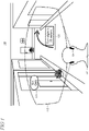
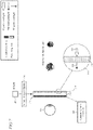
- FIG 1 shows an illustrative augmented reality environment 100, a portion of which is rendered within the field of view of a user of a head-mounted display (HMD) device.
- An augmented reality environment typically combines real-world elements and computer-generated virtual elements to enable a variety of user experiences.
- a user 102 can employ an HMD device 104 to experience an augmented reality environment 100 that is rendered visually on an optics display and may include audio and/or tactile/haptic sensations in some implementations.
- the HMD device user 102 is physically walking in a real-world urban area that includes city streets with various buildings, stores, etc.
- the field of view (FOV), represented by the area 110 in FIG 1 , of the cityscape supported on HMD device 104 changes as the user moves through the environment and the device can render virtual images over the real-world view.
- the virtual images illustratively include a tag 115 that identifies a restaurant business and directions 120 to a place of interest in the city.
- Augmented reality display systems used in HMD and other devices that are implemented using diffractive optical waveguides typically produce virtual images in a virtual image plane that appears at a constant distance from the user's eyes.
- the real-world objects in the FOV can be located at any distance. For example, as shown in FIG 1 the plant outside the restaurant is relatively closer to the user while the package at the end of the street is relatively farther from the user.
- a discrepancy can be manifested between a given real-world object and a virtual image in which only one of them is in focus. This focus mismatch can cause image blur and create eye stress and/or cognitive dissonance in some instances.
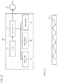
- FIG 2 shows a block diagram of an illustrative near-eye display system 200 that can be configured to provide variable focus for virtual images in an augmented reality environment.
- the near-eye display system uses a combination of diffractive optical elements (DOEs) that provide in-coupling of incident light into a waveguide, exit pupil expansion in two directions, and out-coupling of light out of the waveguide.
- DOEs diffractive optical elements
- Near-eye display systems are frequently used, for example, in head mounted display (HMD) devices in industrial, commercial, and consumer applications. Other devices and systems may also use polarization-sensitive gratings, as described below.
- the near-eye display system 100 is an example that is used to illustrate various features and aspects, and the polarization-sensitive gratings are not necessarily limited to near-eye display systems using DOEs.
- System 200 may include an imager 205 that works with an optical system 210 to deliver images as a virtual display to a user's eye 215.
- the imager 205 may include, for example, RGB (red, green, blue) light emitting diodes (LEDs), LCOS (liquid crystal on silicon) devices, OLED (organic light emitting diode) arrays, MEMS (micro-electro mechanical system) devices, or any other suitable displays or micro-displays operating in transmission, reflection, or emission.
- the imager 205 may also include mirrors and other components that enable a virtual display to be composed and provide one or more input optical beams to the optical system.
- the optical system 210 can typically include magnifying optics 220, pupil forming optics 225, and one or more waveguides 230.
- the imager does not actually shine the images on a surface such as a glass lens to create the visual display for the user. This is not feasible because the human eye cannot focus on something that is that close.
- the near-eye optical system 200 uses the pupil forming optics 225 to form a pupil and the eye 215 acts as the last element in the optical chain and converts the light from the pupil into an image on the eye's retina as a virtual display.
- the waveguide 230 facilitates light transmission between the imager and the eye.
- One or more waveguides can be utilized in the near-eye display system 200 because they are transparent and because they are generally small and lightweight (which is desirable in applications such as HMD devices where size and weight is generally sought to be minimized for reasons of performance and user comfort).
- the waveguide 230 can enable the imager 205 to be located out of the way, for example, on the side of the head, leaving only a relatively small, light, and transparent waveguide optical element in front of the eyes.
- the waveguide 230 operates using a principle of total internal reflection, as shown in FIG 3 , so that light can be coupled among the various optical elements in the system 100.
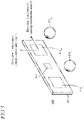
- FIG 4 shows a view of an illustrative exit pupil expander (EPE) 405.
- EPE 405 receives an input optical beam from the imager 205 through magnifying optics 220 to produce one or more output optical beams with expanded exit pupil in one or two directions relative to the exit pupil of the imager (in general, the input may include more than one optical beam which may be produced by separate sources).
- the expanded exit pupil typically facilitates a virtual display to be sufficiently sized to meet the various design requirements of a given optical system, such as image resolution, field of view, and the like, while enabling the imager and associated components to be relatively light and compact.
- the EPE 405 is configured, in this illustrative example, to support binocular operation for both the left and right eyes. Components that may be utilized for stereoscopic operation such as scanning mirrors, lenses, filters, beam splitters, MEMS devices, or the like are not shown in FIG 4 for sake of clarity in exposition.
- the EPE 405 utilizes two out-coupling gratings, 410 L and 410 R that are supported on a waveguide 430 and a central in-coupling grating 440.
- the in-coupling and out-coupling gratings may be configured using multiple DOEs, as described in the illustrative example described below and shown in FIG 8 . While the EPE 405 is depicted as having a planar configuration, other shapes may also be utilized including, for example, curved or partially spherical shapes, in which case the gratings disposed thereon are non-co-planar.
- the EPE 405 may be configured to provide an expanded exit pupil in two directions (i.e., along each of a first and second coordinate axis). As shown, the exit pupil is expanded in both the vertical and horizontal directions.
- direction i.e., along each of a first and second coordinate axis
- vertical primarily to establish relative orientations in the illustrative examples shown and described herein for ease of description. These terms may be intuitive for a usage scenario in which the user of the near-eye display device is upright and forward facing, but less intuitive for other usage scenarios. The listed terms are not to be construed to limit the scope of the configurations (and usage scenarios therein) of the present augmented reality display system with variable focus.
- FIG 6 One exemplary existing solution is shown in which lenses are located on each side of a diffractive waveguide used in an EPE or other imaging display to deliver virtual images and/or objects 602 received from the imager 205 to the user's eye 215.
- a focusing lens 605 or combination of multiple lenses is located on the eye-side of a diffractive waveguide 610.
- a compensating lens 615 is located on the front, light-incident side (i.e., real-world-side) of the diffractive waveguide 610.
- the focusing lens 605 is configured to vary the focus of the virtual images so that the virtual image can stay focused at varying distances in the real world.
- the compensating lens 615 on the real-world side of the waveguide compensates for the effects of the focus lens on the real world so that image planes of the real-world objects (e.g., objects 620) remain unaltered.
- the focus lens 605 and compensating lens 615 are operatively coupled to a suitable compensation system 625 that dynamically operates the lenses to keep the real-world images at the correct distance within the user's FOV as the user's gaze changes.
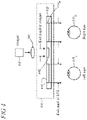
- FIG 7 shows a single lens arrangement in which a polarizing filter 715 is disposed on the front, real-world-side of a diffractive waveguide 710 used, for example, in an EPE in a near-eye display system.
- a diffractive waveguide is utilized in this particular illustrative example, other types of waveguides may also be utilized in alternative implementations.
- such waveguides include refractive waveguides, reflective waveguides, holographic waveguides, polarized waveguides, and prism waveguides.
- An electrically-modulated tunable liquid crystal (LC) lens 718 is disposed on the back, eye-side of the waveguide 710 and is configured, in this particular illustrative example, to act only upon light in a TM-polarized state to implement variable focus.
- the tunable LC lens 718 may be configured to act on TE-polarized light.
- the tunable LC lens may be configured to interoperate with controller 750 that provides electrical modulation to a layer of LC material in the lens to activate the material to achieve a specific optical curvature profile for the lens.
- the modulation is performed responsively to control signals (not shown) provided by various control and/or operating systems and the like supported on a given device such as an HMD device.
- the tunable LC lens 718 is described in more detail below in the text accompanying FIG 11 .
- the polarizing filter 715 may be embodied using a separate layer, as shown in this particular illustrative example, but the filter can also be directly incorporated into the structure of the waveguide 710 in whole or part.
- the polarizing filter 715 can be partially or fully implemented as a discrete optical element that is separate from the waveguide, and/or the filter may incorporate its own waveguide structure.
- the polarizing filter 715 can be configured and shaped to suit a given application.
- the filter can be planar, curved, or use a combination of planar and curved elements.
- the polarizing filter can be incorporated into a protective shield, lens, or other suitable component of a display system.
- the polarizing filter can be implemented using a molded polymer substrate in some implementations which may be beneficial in applications where weight and bulk is sought to be minimized, such as in HMD systems and devices.
- the polarizing filter 715 is linearly polarizing so that unpolarized light 705 impinging on the optical display system from the external real world (e.g., from real-world objects 720) enters the system as TM-polarized light, as indicated by arrow 725.
- the polarizing filter 715 can be configured to filter the impinging unpolarized light into TE-polarized light.
- the filter 715 can also be configured to impose circular polarization (e.g., left- or right-hand circular polarization) in some cases.
- the optical system including the imager 205 and diffractive waveguide 710 is configured so that the virtual images/objects 702 are out-coupled in a TE-polarization state through the tunable LC lens 718 to the user's eye 215 (in alternative implementations, the out-coupled virtual images can be in TM-polarized state when the polarizing filter is configured to pass TE-polarized light).
- the out-coupled virtual images can be acted upon by the tunable LC lens 718 to impart variable focus.
- the tunable LC lens is configured for sensitivity to TE-polarized light therefore it does not affect the focus of TM-polarized light from the real world.
- the combination of the polarizing filter, polarization-sensitive out-coupling, and polarization-sensitive tunable LC lens can thus eliminate the need for an additional compensating lens as utilized in the multiple lens solution discussed above.
- the polarization sensitive out-coupling may be implemented, for example, by configuring the diffractive waveguide to out-couple TE-polarized light to the tunable LC lens while passing through non-TE-polarized light (i.e., TM-polarized light) without diffracting it out to the tunable LC lens.
- the light engine in the imager 205 may be configured to output TE-polarized light, and in other implementations both the imager and diffractive waveguide may be configured with sensitivity to TE-polarization.
- FIG 8 shows an illustrative arrangement 800 of three DOEs that may be used with, or as a part of, a diffractive waveguide to provide in-coupling, expansion of the exit pupil in two directions, and out-coupling in an EPE in which the out-coupling DOE is implemented as a polarization-sensitive grating.
- the polarization-sensitive out-coupling DOE operates to out-couple TE-polarized imaging light to the tunable LC lens (not shown).
- DOEs are utilized for in-coupling and out-coupling, however in other implementations either or both the in-coupling and out-coupling may be performed using one or more of dichroic mirrors, polarization-selective coatings or materials, or prism structures that operate in refraction or reflection.
- Each DOE is an optical element comprising a periodic structure that can modulate various properties of light in a periodic pattern such as the direction of optical axis, optical path length, and the like.
- the first DOE, DOE 1 (indicated by reference numeral 805), is configured to couple an imaging beam from an imager into the waveguide.
- the imaging beam can be TE-polarized in some implementations or randomly polarized (i.e., unpolarized) light may be utilized.
- the second DOE, DOE 2 (810) expands the exit pupil in a first direction along a first coordinate axis
- the third DOE, DOE 3 expands the exit pupil in a second direction along a second coordinate axis and couples light out of the waveguide (it is noted that the various directions of propagation in FIG 8 are depicted in an arbitrary manner and that the directions are not necessarily orthogonal).
- DOE 1 thus functions as an in-coupling grating and DOE 3 functions as an out-coupling grating while expanding the pupil in one direction.
- DOE 2 may be considered as an intermediate grating that functions to couple light between the in-coupling and out-coupling gratings while performing exit pupil expansion in another direction. Using such intermediate grating may eliminate a need for conventional functionalities for exit pupil expansion in an EPE such as collimating lenses.
- DOE 3 is configured to be polarization-sensitive so that it diffracts only TE-polarized light out of the grating. The TM-polarized light, which is not acted upon by the tunable LC lens (due to its sensitivity to only TE-polarized light as described above), is passed out of DOE 3 without being out-coupled by diffraction.
- This polarization-sensitive out-coupling function for TE-polarized light is representatively shown in FIG 8 by reference numeral 825 while the pass-through function for TM-polarized light is representatively indicated by reference numeral 830.
- the tunable LC lens can thus act on the out-coupled virtual images to impart variable focus due to the TE-polarization sensitivity of the lens.
- polarization sensitivity can be implemented in various portions of one or more of the DOEs in the arrangement 800.
- the DOE portions can include grating structures and/or other features configured to perform a conversion from one polarization state to another so that an input at the in-coupling grating DOE 1 in one polarization state (e.g., TM-polarized) is converted by the grating features to the other polarization state (e.g., TE-polarized) prior to being out-coupled from the out-coupling grating DOE 3.
- one or more of the DOEs can be configured with polarization sensitivity to diffract TE-polarized light to the tunable LC lens to thereby impart variable focus to the virtual images.
- the three-dimensional microstructure forming the out-coupling grating, DOE 3 can be configured to be polarization-sensitive by manipulating a combination of grating parameters that relate to grating line asymmetry and fill ratio.
- Grating depth is another exemplary parameter that can be manipulated in combination with grating line asymmetry and fill ratio in some cases.
- These parameters can be selected, adjusted, and/or tuned to implement polarization sensitivity in DOE 3 so that only TE-polarized light from the imager is out-coupled from DOE 3 while TM-polarized light passes through DOE 3 with minimal/no diffraction interaction.
- the grating parameters can be iteratively manipulated in a given grating design until polarization-sensitivity is achieved which meets some predetermined criteria.
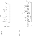
- FIG 9 shows a profile of straight (i.e., non-slanted) grating features 900 (referred to as grating bars, grating lines, or simply "gratings"), that are formed in a substrate 905.
- FIG 10 shows grating features 1000 formed in a substrate 1005 that have an asymmetric profile. That is, the gratings may be slanted (i.e., non-orthogonal) relative to a plane of the waveguide. In implementations where the waveguide is non-planar, then the gratings may be slanted relative to a direction of light propagation in the waveguide.
- Asymmetric grating profiles can also be implemented using blazed gratings, or echelette gratings, in which grooves are formed to create grating features with asymmetric triangular or sawtooth profiles.
- the grating period is represented by d
- the grating height by h also referred to as grating "depth"
- bar width by c
- the slanted gratings in FIG 10 may be described by slant angles ⁇ 1 and ⁇ 2.
- the out-coupling DOE 3 may be configured to be polarization-sensitive by using birefringent materials such as liquid crystal, anisotropic crystal or strained materials.
- gratings can be filled with a liquid crystal material that effectively removes the refractive index contrast for one polarization state.
- FIG 11 shows an exploded view of an illustrative electrically-modulated tunable LC lens, for example lens 718 ( FIG 7 ).
- the lens 718 comprises a layer 1105 of LC material that sits between a top substrate 1110 and a bottom substrate 1115 (it is noted that the terms top and bottom are used for reference purposes and the lens 718 can be used in a variety of orientations depending on the needs of a given application).
- the top and bottom substrates can be made from polymer and/or glass depending on implementation and may further be configured as lenses and/or have other optical characteristics or functions (e.g., filtering, absorbing, polarizing, diffracting, waveguiding, or the like) in some cases.
- the assembled lens is typically configured as a compact package, for example having a few millimeters of thickness depending on application, and can be implemented as a discrete component.
- the tunable LC lens may be located and/or affixed to the eye side of a diffractive waveguide as a thin optical element.
- the tunable LC lens may also be incorporated into a diffractive waveguide, lens system, or other suitable portion or component of an optical display system.
- the LC layer 1105 includes floating electrodes (not shown) that interoperate with concentric ring electrodes 1125 that are located in a bond layer 1130 proximate to the bottom substrate 1115.
- floating electrodes When an electric profile from the controller 750 ( FIG 7 ) is applied through edge conductors (representatively indicated by reference numeral 1135) to a particular region of the LC layer, the floating electrodes slide into place to fill gaps between the concentric electrodes.
- the floating electrodes enable increased optical performance of the tunable lens by reducing light scattering that could otherwise occur in the gaps between the concentric electrodes. Phase sampling across the lens plane is also increased through utilization of the floating electrodes which may further improve lens performance. Charge state in the LC layer is also readily maintained which makes the tunable LC lens highly energy efficient to preserve power which is typically limited in battery-powered systems such as HMD devices.
- the optical wavefront of the LC lens is analog adjustable which enables infinitely-variable focus at any desired power, ranging between the maximum plus and maximum minus optical power of the lens.
- the wavefront shape can be controlled with fine-granularity by applying energy to specific regions of the lens.
- Such fine-grain control can be utilized to control the optics in a given display system to implement not only variable virtual image focus but support various features and user experiences and also correct for aberrations, distortion, refractive errors and the like as well.
- the tunable LC lens can be configured to correct errors in the optical system and/or for deficiencies in the user's vision such as myopia, hyperopia, or astigmatism.
- Such built-in correction in the optical display system can eliminate the need for corrective glasses or contact lenses in some cases when the system in incorporated in devices such as HMD S .
- the tunable LC lens can be configured to impart variable focus to change the focal depth of virtual images, real-world images, or both virtual images and real-world images.
- the polarizing filter may be implemented using LC or other suitable elements that enable control over the polarization state of the real-world light so that the polarization-sensitive LC lens is able to affect the focus of real-world images/objects.
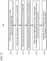
- FIG 12 is a flowchart of an illustrative method 1200. Unless specifically stated, the methods or steps shown in the flowchart and described in the accompanying text are not constrained to a particular order or sequence. In addition, some of the methods or steps thereof can occur or be performed concurrently and not all the methods or steps have to be performed in a given implementation depending on the requirements of such implementation and some methods or steps may be optionally utilized.
- the front of a near-eye display system i.e., a forward-facing portion of the system on which light from the external real world impinges
- a near-eye display system i.e., a forward-facing portion of the system on which light from the external real world impinges
- one or more polarizing filters that are deployed in combination with one or more downstream polarization-sensitive gratings and a tunable LC lens.
- step 1210 light incorporating virtual images from an imager is received at an in-coupling DOE disposed in an EPE.
- the use of the polarizing filter enables light from the external real world to be in a polarization state that is opposite (e.g., orthogonal) to the virtual images that are out-coupled from the EPE to an electrically tunable LC lens, as described below.
- the in-coupling DOE interfaces with a downstream intermediate DOE that is disposed in the EPE.
- the intermediate DOE is configured to interface with a downstream out-coupling DOE.
- the exit pupil of the received light is expanded along a first coordinate axis in the intermediate DOE.
- the exit pupil is expanded along a second coordinate axis in an out-coupling DOE.
- the out-coupling DOE diffracts light out as an output to the tunable LC lens from the EPE with an expanded exit pupil relative to the received light at the in-coupling DOE along the first and second coordinate axes.
- the out-coupling DOE is configured with polarization sensitivity so that it out-couples virtual images to the tunable LC lens in a polarization state that is opposite to the polarized real-world light.
- the tunable LC lens is also polarization-sensitive to the opposite polarization state to that of the real-world light.
- operation of the tunable LC lens does not impact the focus of real-world images which can obviate the need for a conventional compensating lens.
- the tunable LC lens may be electrically controlled to focus the out-coupled virtual images onto a virtual image plane.
- the electrical control can be varied to impart variable focus so that the virtual image plane can be located at different distances to correspond with the locations of objects in the real world.
- Variable focus may be incorporated into a display system that is utilized in a virtual or augmented reality display device.
- a virtual or augmented reality display device may take any suitable form, including but not limited to near-eye devices such as an HMD device.
- a see-through display may be used in some implementations while an opaque (i.e., non-see-through) display using a camera-based pass-through or outward facing sensor, for example, may be used in other implementations.
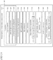
- FIG 13 shows one particular illustrative example of a see-through, augmented reality or virtual reality display system 1300
- FIG 14 shows a functional block diagram of the system 1300
- Display system 1300 comprises one or more lenses 1302 that form a part of a see-through display subsystem 1304, such that images may be displayed using lenses 1302 (e.g. using projection onto lenses 1302, one or more waveguide systems incorporated into the lenses 1302, and/or in any other suitable manner).
- Display system 1300 further comprises one or more outward-facing image sensors 1306 configured to acquire images of a background scene and/or physical environment being viewed by a user, and may include one or more microphones 1308 configured to detect sounds, such as voice commands from a user.
- Outward-facing image sensors 1306 may include one or more depth sensors and/or one or more two-dimensional image sensors.
- an augmented reality or virtual reality display system instead of incorporating a see-through display subsystem, may display augmented reality or virtual reality images through a viewfinder mode for an outward-facing image sensor.
- the display system 1300 may further include a gaze detection subsystem 1310 configured for detecting a direction of gaze of each eye of a user or a direction or location of focus, as described above. Gaze detection subsystem 1310 may be configured to determine gaze directions of each of a user's eyes in any suitable manner.
- a gaze detection subsystem 1310 includes one or more glint sources 1312, such as infrared light sources, that are configured to cause a glint of light to reflect from each eyeball of a user, and one or more image sensors 1314, such as inward-facing sensors, that are configured to capture an image of each eyeball of the user. Changes in the glints from the user's eyeballs and/or a location of a user's pupil, as determined from image data gathered using the image sensor(s) 1314, may be used to determine a direction of gaze.
- glint sources 1312 such as infrared light sources
- image sensors 1314 such as inward-facing sensors
- Gaze detection subsystem 1310 may have any suitable number and arrangement of light sources and image sensors. In some implementations, the gaze detection subsystem 1310 may be omitted.
- the display system 1300 may also include additional sensors.
- display system 1300 may comprise a global positioning system (GPS) subsystem 1316 to allow a location of the display system 1300 to be determined. This may help to identify real-world objects, such as buildings, etc. that may be located in the user's adjoining physical environment.
- GPS global positioning system
- the display system 1300 may further include one or more motion sensors 1318 (e.g., inertial, multi-axis gyroscopic, or acceleration sensors) to detect movement and position/orientation/pose of a user's head when the user is wearing the system as part of an augmented reality or virtual reality HMD device.
- Motion data may be used, potentially along with eye-tracking glint data and outward-facing image data, for gaze detection, as well as for image stabilization to help correct for blur in images from the outward-facing image sensor(s) 1306.
- the use of motion data may allow changes in gaze location to be tracked even if image data from outward-facing image sensor(s) 1306 cannot be resolved.
- motion sensors 1318 as well as microphone(s) 1308 and gaze detection subsystem 1310, also may be employed as user input devices, such that a user may interact with the display system 1300 via gestures of the eye, neck and/or head, as well as via verbal commands in some cases. It may be understood that sensors illustrated in FIGs 13 and 14 and described in the accompanying text are included for the purpose of example and are not intended to be limiting in any manner, as any other suitable sensors and/or combination of sensors may be utilized to meet the needs of a particular implementation.
- biometric sensors e.g., for detecting heart and respiration rates, blood pressure, brain activity, body temperature, etc.
- environmental sensors e.g., for detecting temperature, humidity, elevation, UV (ultraviolet) light levels, etc.
- biometric sensors e.g., for detecting heart and respiration rates, blood pressure, brain activity, body temperature, etc.
- environmental sensors e.g., for detecting temperature, humidity, elevation, UV (ultraviolet) light levels, etc.
- the display system 1300 can further include a controller 1320 having a logic subsystem 1322 and a data storage subsystem 1324 in communication with the sensors, gaze detection subsystem 1310, display subsystem 1304, and/or other components through a communications subsystem 1326.
- the communications subsystem 1326 can also facilitate the display system being operated in conjunction with remotely located resources, such as processing, storage, power, data, and services. That is, in some implementations, an HMD device can be operated as part of a system that can distribute resources and capabilities among different components and subsystems.
- the storage subsystem 1324 may include instructions stored thereon that are executable by logic subsystem 1322, for example, to receive and interpret inputs from the sensors, to identify location and movements of a user, to identify real objects using surface reconstruction and other techniques, and dim/fade the display based on distance to objects so as to enable the objects to be seen by the user, among other tasks.
- the display system 1300 is configured with one or more audio transducers 1328 (e.g., speakers, earphones, etc.) so that audio can be utilized as part of an augmented reality or virtual reality experience.
- a power management subsystem 1330 may include one or more batteries 1332 and/or protection circuit modules (PCMs) and an associated charger interface 1334 and/or remote power interface for supplying power to components in the display system 1300.
- PCMs protection circuit modules
- the display system 1300 is described for the purpose of example, and thus is not meant to be limiting. It may be further understood that the display device may include additional and/or alternative sensors, cameras, microphones, input devices, output devices, etc. than those shown without departing from the scope of the present arrangement. Additionally, the physical configuration of a display device and its various sensors and subcomponents may take a variety of different forms without departing from the scope of the present arrangement.
- an augmented reality display system with variable focus can be used in a mobile or portable electronic device 1500, such as a mobile phone, smartphone, personal digital assistant (PDA), communicator, portable Internet appliance, hand-held computer, digital video or still camera, wearable computer, computer game device, specialized bring-to-the-eye product for viewing, or other portable electronic device.
- the portable device 1500 includes a housing 1505 to house a communication module 1510 for receiving and transmitting information from and to an external device, or a remote system or service (not shown).
- the portable device 1500 may also include an image processing module 1515 for handling the received and transmitted information, and a virtual display system 1520 to support viewing of images.
- the virtual display system 1520 can include a micro-display or an imager 1525 and an optical engine 1530.
- the image processing module 1515 may be operatively connected to the optical engine 1530 to provide image data, such as video data, to the imager 1525 to display an image thereon.
- An EPE 1535 can be optically linked to an optical engine 1530.
- the EPE may incorporate or be part of a display system that supports variable focus for virtual images.
- An augmented reality display system with variable focus may also be utilized in non-portable devices, such as gaming devices, multimedia consoles, personal computers, vending machines, smart appliances, Internet-connected devices, and home appliances, such as an oven, microwave oven and other appliances, and other non-portable devices.
- non-portable devices such as gaming devices, multimedia consoles, personal computers, vending machines, smart appliances, Internet-connected devices, and home appliances, such as an oven, microwave oven and other appliances, and other non-portable devices.
- An example includes an optical display system, comprising: a polarizing filter configured to filter light from real-world objects into a first polarization state; a tunable liquid crystal (LC) lens that is configured to impart variable focus on light that has a second polarization state, the second polarization state being orthogonal to the first polarization state; and a waveguide including an out-coupling element for out-coupling light to the tunable LC lens wherein the out-coupling element is configured for sensitivity to the second polarization state so that only light in the second polarization state is out-coupled to the tunable LC lens and subject to variable focus while light from real-world objects in the first polarization state is not subject to variable focus.
- a polarizing filter configured to filter light from real-world objects into a first polarization state
- a tunable liquid crystal (LC) lens that is configured to impart variable focus on light that has a second polarization state, the second polarization state being orthogonal to the first polarization state
- the waveguide comprises a first diffractive optical element (DOE) having an input surface and configured as an in-coupling grating to receive one or more optical beams from an imager having a second polarization state as an input, a second DOE configured for pupil expansion of the one or more optical beams along a first direction, and a third DOE having an output surface and configured for pupil expansion of the one or more optical beams along a second direction, and further configured as an out-coupling grating to out-couple, as an output to the tunable LC lens from the output surface, one or more optical beams with expanded pupil relative to the input.
- DOE diffractive optical element
- grating features in at least one of the DOEs are configured according to one or more of grating asymmetry, grating depth, or grating fill factor so as to impart polarization-sensitivity to the second polarization state.
- the waveguide is one of diffractive waveguide, refractive waveguide, reflective waveguide, holographic waveguide, prism waveguide, or combinations thereof
- the out-coupling element is one of diffractive optical element, dichroic mirror, polarization-selective coating, or prism, and further comprising an in-coupling element configured to in-couple light into the waveguide in which the in-coupling element is one of diffractive optical element, dichroic mirror, polarization-selective coating, or prism.
- the polarizing filter is disposed in a forward-facing portion of the optical display system upon which light from the real-world objects impinges and the tunable LC lens is disposed in a portion of the optical display system between the waveguide and eyes of a user.
- a further example includes an electronic device supporting an augmented reality experience including virtual images and real-world images, comprising: a data processing unit; an optical engine operatively connected to the data processing unit for receiving image data from the data processing unit and producing virtual images; a polarizing filter configured to filter light from real-world images into a first polarization state; an electrically-modulated tunable liquid crystal (LC) lens configured to impart variable focus to light having a second polarization state that is orthogonal to the first polarization state; and an exit pupil expander, responsive to one or more input optical beams incorporating the virtual images, comprising a structure on which multiple diffractive optical elements (DOEs) are disposed, in which the exit pupil expander is configured to provide one or more out-coupled optical beams, using one or more of the DOEs, as a near-eye display with an expanded exit pupil, and wherein at least one of the DOEs has a portion configured to be polarization-sensitive so the exit pupil expander outputs the virtual images having the second polarization state to the
- the exit pupil expander provides pupil expansion in two directions.
- the electronic device further includes an imager operatively connected to the optical engine to form virtual images based on the image data and to generate one or more input optical beams incorporating the virtual images having the second polarization state.
- the imager includes one of light emitting diode, liquid crystal on silicon device, organic light emitting diode array, or micro-electro mechanical system device.
- the LC lens is configured to impart variable focus to one or more of virtual images or real-world images.
- the electronic device is implemented in a head mounted display device or portable electronic device.
- the LC lens comprises floating electrodes and concentric electrodes wherein the floating electrodes are configured to fill gaps between the concentric electrodes when the LC lens is electrically modulated to assume a particular wavefront shape to thereby impart variable focus to the virtual images.
- the LC lens includes a layer of LC material located between respective top and bottom substrates and further comprising a controller configured to electrically modulate the LC lens to assume the particular wavefront shape to thereby impart focus to the out-coupled optical beams, the controller being adapted to apply an electric profile to various portions of the LC material layer through electrical contacts to the concentric electrodes.
- LC lens is further configured to be infinitely variable between a range of optical powers.
- a further example includes a method for providing variable focus to virtual images in an augmented reality display system that supports virtual images and real-world images, comprising: utilizing a polarizing filter so that the real-world images have a first polarization state; receiving, from an imager, light incorporating virtual images at an in-coupling diffractive optical element (DOE) disposed in an exit pupil expander; expanding an exit pupil of the received virtual images along a first coordinate axis in an intermediate DOE disposed in the exit pupil expander; expanding the exit pupil along a second coordinate axis in an out-coupling DOE disposed in the exit pupil expander; outputting the virtual images to a tunable liquid crystal (LC) lens, the output virtual images having an expanded exit pupil relative to the received light at the in-coupling DOE along the first and second coordinate axes using the out-coupling DOE; and electrically controlling the tunable LC lens to focus the virtual images on a virtual image plane of variable distance away from the system wherein the LC lens is polarization-sensitive whereby the LC
- the first and second polarization states include one of linearly-polarized or circularly-polarized.
- the method is performed in a near-eye display system.
- the electric control comprises analog adjustability of LC material in the lens between various wavefront shapes by application of power to an arrangement of electrodes in the LC lens.
- one or more of the in-coupling DOE, intermediate DOE, or out-coupling DOE include portions having grating features configured to perform a conversion on an input to the in-coupling DOE from the first polarization state to the second polarization state.
- the polarization conversion is performed upstream from the outputting at the out-coupling DOE.
Description
- Augmented reality computing devices, such as head mounted display (HMD) systems and handheld mobile devices (e.g. smart phones, tablet computers, etc.), may be configured to display information to a user about virtual and/or real objects in a field of view of the user and/or a field of view of a camera of the device. For example, an HMD device may be configured to display, using a see-through display system, virtual environments with real-world objects mixed in, or real-world environments with virtual objects mixed in. Similarly, a mobile device may display such information using a camera viewfinder window.
- Hung-Shan Chen et al. "Electrically adjustable location of a protected image in augmented reality via a liquid-crystal lens" Optics Express vol. 23, no. 22, 19 October 2015 describes an augmented reality system involving the electrically tunable location of a projected image is implemented using a liquid-crystal (LC) lens. The projected image is either real or virtual. By effectively doubling the LC lens power following light reflection, the position of a projected virtual image can be made to vary.
-
WO2015184412 (A1 ) teaches configurations are disclosed for presenting virtual reality and augmented reality experiences to users. The system may comprise a spatial light modulator operatively coupled to an image source for projecting light associated with one or more frames of image data, and a variable focus element (VFE) for varying a focus of the projected light such that a first frame of image data is focused at a first depth plane, and a second frame of image data is focused at a second depth plane, and wherein a distance between the first depth plane and the second depth plane is fixed. - Liwei Li et al. "Liquid crystal lens with concentric electrodes and inter-electrode resistors" Liquid Crystals Reviews, vol. 2, no. 2, 3 July 2014 describes an overview of recent efforts in designing high-quality tunable liquid crystal (LC) lenses with concentric electrodes. The design concepts are introduced and details about fabrication and evaluation methods are given.
- According to aspects of the present invention there is provided a display and device as defined in the accompanying claims. A near-eye optical display system that may be utilized in augmented reality applications and devices includes a waveguide having optical elements configured for in-coupling, exit pupil expansion, and out-coupling. An electrically-modulated tunable liquid crystal (LC) lens is located between the waveguide and the eyes of the user. A polarizing filter is located on the other side of the waveguide so that light from the real world enters the system with a particular polarization state, for example, TM-polarized. The tunable LC lens is configured to impart variable focus on light that has an opposite polarization state, for example TE-polarized. The optical display system is arranged to be polarization-sensitive so that virtual images from an imager are out-coupled from the waveguide with TE-polarization. The tunable LC lens may thus impart variable focus to the virtual images due to the lens' sensitivity to TE-polarization. However, because the real-world images are TM-polarized, they are not subject to the focusing by the tunable LC lens and reach the user's eye without being affected. The combination of the polarizing filter, polarization-sensitive out-coupling, and polarization-sensitive tunable LC lens provides for variable focus for virtual images while eliminating the need for an additional compensating lens that may be utilized in conventional variable focus solutions.
- In an illustrative example, the waveguide is arranged as a diffractive waveguide that includes one or more diffractive optical elements (DOEs) for the in-coupling, exit pupil expansion, and out-coupling. In alternative implementations, the waveguide may be configured using one or more of refractive waveguide, reflective waveguide, polarized waveguide, holographic waveguide, or prism waveguide and the in-coupling and out-coupling may be performed using one or more of dichroic mirrors, polarization-selective coatings or materials, or prism structures that operate in refraction or reflection.
- This Summary is provided to introduce a selection of concepts in a simplified form that are further described below in the Detailed Description. This Summary is not intended to identify key features or essential features of the claimed subject matter, nor is it intended to be used as an aid in determining the scope of the claimed subject matter. Furthermore, the claimed subject matter is not limited to implementations that solve any or all disadvantages noted in any part of this disclosure.
-
-
FIG 1 shows an illustrative augmented reality environment, a portion of which is rendered within the field of view of a user of a head-mounted display (HMD) device; -
FIG 2 shows a block diagram of an illustrative near-eye display system that can provide variable focus for virtual images in an augmented reality environment; -
FIG 3 shows propagation of light in a waveguide by total internal reflection; -
FIG 4 shows a view of an illustrative exit pupil expander; -
FIG 5 shows a view of the illustrative exit pupil expander in which the exit pupil is expanded along two directions; -
FIG 6 shows an illustrative arrangement for implementing variable focus using a lens for changing the image plane for virtual images and a compensating lens; -
FIG 7 shows an illustrative arrangement for implementing variable focus using a tunable liquid crystal (LC) lens that eliminates the need for a compensating lens; -
FIG 8 shows an illustrative arrangement of three DOEs configured for in-coupling, exit pupil expansion, and out-coupling in which the out-coupling DOE is implemented using a polarization-sensitive grating; -
FIG 9 shows a profile of a portion of an illustrative diffraction grating that has straight gratings; -
FIG 10 shows an asymmetric profile of a portion of an illustrative diffraction grating that has asymmetric or slanted gratings; -
FIG 11 shows an exploded view of an illustrative tunable LC lens; -
FIG 12 shows an illustrative method; -
FIG 13 is a pictorial view of an illustrative example of a virtual reality or augmented reality head mounted display (HMD) device; -
FIG 14 shows a block diagram of an illustrative example of a virtual reality or augmented reality HMD device; and -
FIG 15 shows a block diagram of an illustrative electronic device that incorporates an augmented reality display system with variable focus. - Like reference numerals indicate like elements in the drawings. Elements are not drawn to scale unless otherwise indicated.
-
FIG 1 shows an illustrative augmentedreality environment 100, a portion of which is rendered within the field of view of a user of a head-mounted display (HMD) device. An augmented reality environment typically combines real-world elements and computer-generated virtual elements to enable a variety of user experiences. In the illustrative example shown inFIG 1 , auser 102 can employ anHMD device 104 to experience an augmentedreality environment 100 that is rendered visually on an optics display and may include audio and/or tactile/haptic sensations in some implementations. In this particular non-limiting example, the HMDdevice user 102 is physically walking in a real-world urban area that includes city streets with various buildings, stores, etc. The field of view (FOV), represented by thearea 110 inFIG 1 , of the cityscape supported onHMD device 104 changes as the user moves through the environment and the device can render virtual images over the real-world view. Here, the virtual images illustratively include atag 115 that identifies a restaurant business anddirections 120 to a place of interest in the city. - Augmented reality display systems used in HMD and other devices that are implemented using diffractive optical waveguides typically produce virtual images in a virtual image plane that appears at a constant distance from the user's eyes. However, the real-world objects in the FOV can be located at any distance. For example, as shown in
FIG 1 the plant outside the restaurant is relatively closer to the user while the package at the end of the street is relatively farther from the user. Thus, a discrepancy can be manifested between a given real-world object and a virtual image in which only one of them is in focus. This focus mismatch can cause image blur and create eye stress and/or cognitive dissonance in some instances. -
FIG 2 shows a block diagram of an illustrative near-eye display system 200 that can be configured to provide variable focus for virtual images in an augmented reality environment. By implementing variable focus for virtual images, the focus discrepancy between virtual images and the real-world can be reduced or eliminated. In an illustrative embodiment, the near-eye display system uses a combination of diffractive optical elements (DOEs) that provide in-coupling of incident light into a waveguide, exit pupil expansion in two directions, and out-coupling of light out of the waveguide. Near-eye display systems are frequently used, for example, in head mounted display (HMD) devices in industrial, commercial, and consumer applications. Other devices and systems may also use polarization-sensitive gratings, as described below. The near-eye display system 100 is an example that is used to illustrate various features and aspects, and the polarization-sensitive gratings are not necessarily limited to near-eye display systems using DOEs. -
System 200 may include animager 205 that works with anoptical system 210 to deliver images as a virtual display to a user'seye 215. Theimager 205 may include, for example, RGB (red, green, blue) light emitting diodes (LEDs), LCOS (liquid crystal on silicon) devices, OLED (organic light emitting diode) arrays, MEMS (micro-electro mechanical system) devices, or any other suitable displays or micro-displays operating in transmission, reflection, or emission. Theimager 205 may also include mirrors and other components that enable a virtual display to be composed and provide one or more input optical beams to the optical system. Theoptical system 210 can typically include magnifyingoptics 220,pupil forming optics 225, and one ormore waveguides 230. - In a near-eye display system the imager does not actually shine the images on a surface such as a glass lens to create the visual display for the user. This is not feasible because the human eye cannot focus on something that is that close. Rather than create a visible image on a surface, the near-eye
optical system 200 uses thepupil forming optics 225 to form a pupil and theeye 215 acts as the last element in the optical chain and converts the light from the pupil into an image on the eye's retina as a virtual display. - The
waveguide 230 facilitates light transmission between the imager and the eye. One or more waveguides can be utilized in the near-eye display system 200 because they are transparent and because they are generally small and lightweight (which is desirable in applications such as HMD devices where size and weight is generally sought to be minimized for reasons of performance and user comfort). For example, thewaveguide 230 can enable theimager 205 to be located out of the way, for example, on the side of the head, leaving only a relatively small, light, and transparent waveguide optical element in front of the eyes. In one implementation, thewaveguide 230 operates using a principle of total internal reflection, as shown inFIG 3 , so that light can be coupled among the various optical elements in thesystem 100. -
FIG 4 shows a view of an illustrative exit pupil expander (EPE) 405.EPE 405 receives an input optical beam from theimager 205 through magnifyingoptics 220 to produce one or more output optical beams with expanded exit pupil in one or two directions relative to the exit pupil of the imager (in general, the input may include more than one optical beam which may be produced by separate sources). The expanded exit pupil typically facilitates a virtual display to be sufficiently sized to meet the various design requirements of a given optical system, such as image resolution, field of view, and the like, while enabling the imager and associated components to be relatively light and compact. - The
EPE 405 is configured, in this illustrative example, to support binocular operation for both the left and right eyes. Components that may be utilized for stereoscopic operation such as scanning mirrors, lenses, filters, beam splitters, MEMS devices, or the like are not shown inFIG 4 for sake of clarity in exposition. TheEPE 405 utilizes two out-coupling gratings, 410L and 410R that are supported on awaveguide 430 and a central in-coupling grating 440. The in-coupling and out-coupling gratings may be configured using multiple DOEs, as described in the illustrative example described below and shown inFIG 8 . While theEPE 405 is depicted as having a planar configuration, other shapes may also be utilized including, for example, curved or partially spherical shapes, in which case the gratings disposed thereon are non-co-planar. - As shown in
FIG 5 , theEPE 405 may be configured to provide an expanded exit pupil in two directions (i.e., along each of a first and second coordinate axis). As shown, the exit pupil is expanded in both the vertical and horizontal directions. It may be understood that the terms "direction," "horizontal," and "vertical" are used primarily to establish relative orientations in the illustrative examples shown and described herein for ease of description. These terms may be intuitive for a usage scenario in which the user of the near-eye display device is upright and forward facing, but less intuitive for other usage scenarios. The listed terms are not to be construed to limit the scope of the configurations (and usage scenarios therein) of the present augmented reality display system with variable focus. - As discussed above, conventional near-eye display systems using diffractive gratings typically provide a virtual image plane that is located at a constant distance from the user's eyes which can give rise to a discrepancy between real-world and virtual image focus. A variety of solutions have been implemented to provide variable virtual image focus. One exemplary existing solution is shown in
FIG 6 in which lenses are located on each side of a diffractive waveguide used in an EPE or other imaging display to deliver virtual images and/orobjects 602 received from theimager 205 to the user'seye 215. - A focusing
lens 605 or combination of multiple lenses is located on the eye-side of adiffractive waveguide 610. A compensatinglens 615 is located on the front, light-incident side (i.e., real-world-side) of thediffractive waveguide 610. The focusinglens 605 is configured to vary the focus of the virtual images so that the virtual image can stay focused at varying distances in the real world. The compensatinglens 615 on the real-world side of the waveguide compensates for the effects of the focus lens on the real world so that image planes of the real-world objects (e.g., objects 620) remain unaltered. In some implementations, thefocus lens 605 and compensatinglens 615 are operatively coupled to asuitable compensation system 625 that dynamically operates the lenses to keep the real-world images at the correct distance within the user's FOV as the user's gaze changes. - While the multiple lens solution shown in
FIG 6 can produce satisfactory results in some implementations, it can be sub-optimal in applications such as HMD in which low weight and/or cost is an important design parameter. In comparison to multiple lens solution,FIG 7 shows a single lens arrangement in which apolarizing filter 715 is disposed on the front, real-world-side of adiffractive waveguide 710 used, for example, in an EPE in a near-eye display system. While a diffractive waveguide is utilized in this particular illustrative example, other types of waveguides may also be utilized in alternative implementations. For example, such waveguides include refractive waveguides, reflective waveguides, holographic waveguides, polarized waveguides, and prism waveguides. - An electrically-modulated tunable liquid crystal (LC)
lens 718 is disposed on the back, eye-side of thewaveguide 710 and is configured, in this particular illustrative example, to act only upon light in a TM-polarized state to implement variable focus. In other implementations, thetunable LC lens 718 may be configured to act on TE-polarized light. The tunable LC lens may be configured to interoperate withcontroller 750 that provides electrical modulation to a layer of LC material in the lens to activate the material to achieve a specific optical curvature profile for the lens. In typical implementations the modulation is performed responsively to control signals (not shown) provided by various control and/or operating systems and the like supported on a given device such as an HMD device. Thetunable LC lens 718 is described in more detail below in the text accompanyingFIG 11 . - The
polarizing filter 715 may be embodied using a separate layer, as shown in this particular illustrative example, but the filter can also be directly incorporated into the structure of thewaveguide 710 in whole or part. In some implementations, thepolarizing filter 715 can be partially or fully implemented as a discrete optical element that is separate from the waveguide, and/or the filter may incorporate its own waveguide structure. Thepolarizing filter 715 can be configured and shaped to suit a given application. For example, the filter can be planar, curved, or use a combination of planar and curved elements. In some applications, the polarizing filter can be incorporated into a protective shield, lens, or other suitable component of a display system. The polarizing filter can be implemented using a molded polymer substrate in some implementations which may be beneficial in applications where weight and bulk is sought to be minimized, such as in HMD systems and devices. - In this illustrative example, the
polarizing filter 715 is linearly polarizing so thatunpolarized light 705 impinging on the optical display system from the external real world (e.g., from real-world objects 720) enters the system as TM-polarized light, as indicated byarrow 725. In other implementations, thepolarizing filter 715 can be configured to filter the impinging unpolarized light into TE-polarized light. Thefilter 715 can also be configured to impose circular polarization (e.g., left- or right-hand circular polarization) in some cases. - The optical system including the
imager 205 anddiffractive waveguide 710 is configured so that the virtual images/objects 702 are out-coupled in a TE-polarization state through thetunable LC lens 718 to the user's eye 215 (in alternative implementations, the out-coupled virtual images can be in TM-polarized state when the polarizing filter is configured to pass TE-polarized light). As the out-coupled virtual images have a TE-polarization state, they can be acted upon by thetunable LC lens 718 to impart variable focus. However, the tunable LC lens is configured for sensitivity to TE-polarized light therefore it does not affect the focus of TM-polarized light from the real world. The combination of the polarizing filter, polarization-sensitive out-coupling, and polarization-sensitive tunable LC lens can thus eliminate the need for an additional compensating lens as utilized in the multiple lens solution discussed above. - The polarization sensitive out-coupling may be implemented, for example, by configuring the diffractive waveguide to out-couple TE-polarized light to the tunable LC lens while passing through non-TE-polarized light (i.e., TM-polarized light) without diffracting it out to the tunable LC lens. In some implementations, the light engine in the
imager 205 may be configured to output TE-polarized light, and in other implementations both the imager and diffractive waveguide may be configured with sensitivity to TE-polarization. -
FIG 8 shows anillustrative arrangement 800 of three DOEs that may be used with, or as a part of, a diffractive waveguide to provide in-coupling, expansion of the exit pupil in two directions, and out-coupling in an EPE in which the out-coupling DOE is implemented as a polarization-sensitive grating. The polarization-sensitive out-coupling DOE operates to out-couple TE-polarized imaging light to the tunable LC lens (not shown). In this particular illustrative example, DOEs are utilized for in-coupling and out-coupling, however in other implementations either or both the in-coupling and out-coupling may be performed using one or more of dichroic mirrors, polarization-selective coatings or materials, or prism structures that operate in refraction or reflection. - Each DOE is an optical element comprising a periodic structure that can modulate various properties of light in a periodic pattern such as the direction of optical axis, optical path length, and the like. The first DOE, DOE 1 (indicated by reference numeral 805), is configured to couple an imaging beam from an imager into the waveguide. The imaging beam can be TE-polarized in some implementations or randomly polarized (i.e., unpolarized) light may be utilized. The second DOE, DOE 2 (810), expands the exit pupil in a first direction along a first coordinate axis, and the third DOE, DOE 3 (815), expands the exit pupil in a second direction along a second coordinate axis and couples light out of the waveguide (it is noted that the various directions of propagation in
FIG 8 are depicted in an arbitrary manner and that the directions are not necessarily orthogonal). -
DOE 1 thus functions as an in-coupling grating andDOE 3 functions as an out-coupling grating while expanding the pupil in one direction.DOE 2 may be considered as an intermediate grating that functions to couple light between the in-coupling and out-coupling gratings while performing exit pupil expansion in another direction. Using such intermediate grating may eliminate a need for conventional functionalities for exit pupil expansion in an EPE such as collimating lenses. In this particular example,DOE 3 is configured to be polarization-sensitive so that it diffracts only TE-polarized light out of the grating. The TM-polarized light, which is not acted upon by the tunable LC lens (due to its sensitivity to only TE-polarized light as described above), is passed out ofDOE 3 without being out-coupled by diffraction. - This polarization-sensitive out-coupling function for TE-polarized light is representatively shown in
FIG 8 byreference numeral 825 while the pass-through function for TM-polarized light is representatively indicated byreference numeral 830. The tunable LC lens can thus act on the out-coupled virtual images to impart variable focus due to the TE-polarization sensitivity of the lens. In alternative implementations, polarization sensitivity can be implemented in various portions of one or more of the DOEs in thearrangement 800. For example, the DOE portions can include grating structures and/or other features configured to perform a conversion from one polarization state to another so that an input at the in-coupling grating DOE 1 in one polarization state (e.g., TM-polarized) is converted by the grating features to the other polarization state (e.g., TE-polarized) prior to being out-coupled from the out-coupling grating DOE 3. In another illustrative implementation, one or more of the DOEs can be configured with polarization sensitivity to diffract TE-polarized light to the tunable LC lens to thereby impart variable focus to the virtual images. - The three-dimensional microstructure forming the out-coupling grating,
DOE 3, can be configured to be polarization-sensitive by manipulating a combination of grating parameters that relate to grating line asymmetry and fill ratio. Grating depth is another exemplary parameter that can be manipulated in combination with grating line asymmetry and fill ratio in some cases. These parameters can be selected, adjusted, and/or tuned to implement polarization sensitivity inDOE 3 so that only TE-polarized light from the imager is out-coupled fromDOE 3 while TM-polarized light passes throughDOE 3 with minimal/no diffraction interaction. In some implementations, the grating parameters can be iteratively manipulated in a given grating design until polarization-sensitivity is achieved which meets some predetermined criteria. - Grating line asymmetry is described in more detail while making reference to
FIGs 9 and 10. FIG 9 shows a profile of straight (i.e., non-slanted) grating features 900 (referred to as grating bars, grating lines, or simply "gratings"), that are formed in asubstrate 905. By comparison,FIG 10 showsgrating features 1000 formed in asubstrate 1005 that have an asymmetric profile. That is, the gratings may be slanted (i.e., non-orthogonal) relative to a plane of the waveguide. In implementations where the waveguide is non-planar, then the gratings may be slanted relative to a direction of light propagation in the waveguide. Asymmetric grating profiles can also be implemented using blazed gratings, or echelette gratings, in which grooves are formed to create grating features with asymmetric triangular or sawtooth profiles. InFIGs 9 and 10 , the grating period is represented by d, the grating height by h (also referred to as grating "depth"), bar width by c, and the fill factor by f, where f =c/d. The slanted gratings inFIG 10 may be described by slant angles α1 and α2. - In alternative embodiments, the out-
coupling DOE 3 may be configured to be polarization-sensitive by using birefringent materials such as liquid crystal, anisotropic crystal or strained materials. In some implementations, gratings can be filled with a liquid crystal material that effectively removes the refractive index contrast for one polarization state. -
FIG 11 shows an exploded view of an illustrative electrically-modulated tunable LC lens, for example lens 718 (FIG 7 ). Thelens 718 comprises alayer 1105 of LC material that sits between atop substrate 1110 and a bottom substrate 1115 (it is noted that the terms top and bottom are used for reference purposes and thelens 718 can be used in a variety of orientations depending on the needs of a given application). The top and bottom substrates can be made from polymer and/or glass depending on implementation and may further be configured as lenses and/or have other optical characteristics or functions (e.g., filtering, absorbing, polarizing, diffracting, waveguiding, or the like) in some cases. The assembled lens is typically configured as a compact package, for example having a few millimeters of thickness depending on application, and can be implemented as a discrete component. For example, the tunable LC lens may be located and/or affixed to the eye side of a diffractive waveguide as a thin optical element. The tunable LC lens may also be incorporated into a diffractive waveguide, lens system, or other suitable portion or component of an optical display system. - The
LC layer 1105 includes floating electrodes (not shown) that interoperate withconcentric ring electrodes 1125 that are located in abond layer 1130 proximate to thebottom substrate 1115. When an electric profile from the controller 750 (FIG 7 ) is applied through edge conductors (representatively indicated by reference numeral 1135) to a particular region of the LC layer, the floating electrodes slide into place to fill gaps between the concentric electrodes. The floating electrodes enable increased optical performance of the tunable lens by reducing light scattering that could otherwise occur in the gaps between the concentric electrodes. Phase sampling across the lens plane is also increased through utilization of the floating electrodes which may further improve lens performance. Charge state in the LC layer is also readily maintained which makes the tunable LC lens highly energy efficient to preserve power which is typically limited in battery-powered systems such as HMD devices. - By controlling the electric profile applied to various portions of the
LC layer 1105, the optical wavefront of the LC lens is analog adjustable which enables infinitely-variable focus at any desired power, ranging between the maximum plus and maximum minus optical power of the lens. In addition, the wavefront shape can be controlled with fine-granularity by applying energy to specific regions of the lens. Such fine-grain control can be utilized to control the optics in a given display system to implement not only variable virtual image focus but support various features and user experiences and also correct for aberrations, distortion, refractive errors and the like as well. For example, in some implementations, the tunable LC lens can be configured to correct errors in the optical system and/or for deficiencies in the user's vision such as myopia, hyperopia, or astigmatism. Such built-in correction in the optical display system can eliminate the need for corrective glasses or contact lenses in some cases when the system in incorporated in devices such as HMDS. - In some implementations, the tunable LC lens can be configured to impart variable focus to change the focal depth of virtual images, real-world images, or both virtual images and real-world images. For example, the polarizing filter may be implemented using LC or other suitable elements that enable control over the polarization state of the real-world light so that the polarization-sensitive LC lens is able to affect the focus of real-world images/objects.
-
FIG 12 is a flowchart of anillustrative method 1200. Unless specifically stated, the methods or steps shown in the flowchart and described in the accompanying text are not constrained to a particular order or sequence. In addition, some of the methods or steps thereof can occur or be performed concurrently and not all the methods or steps have to be performed in a given implementation depending on the requirements of such implementation and some methods or steps may be optionally utilized. - In
step 1205, the front of a near-eye display system (i.e., a forward-facing portion of the system on which light from the external real world impinges) is configured to utilize one or more polarizing filters that are deployed in combination with one or more downstream polarization-sensitive gratings and a tunable LC lens. Instep 1210, light incorporating virtual images from an imager is received at an in-coupling DOE disposed in an EPE. The use of the polarizing filter enables light from the external real world to be in a polarization state that is opposite (e.g., orthogonal) to the virtual images that are out-coupled from the EPE to an electrically tunable LC lens, as described below. The in-coupling DOE interfaces with a downstream intermediate DOE that is disposed in the EPE. The intermediate DOE is configured to interface with a downstream out-coupling DOE. - In
step 1215, the exit pupil of the received light is expanded along a first coordinate axis in the intermediate DOE. Instep 1220, the exit pupil is expanded along a second coordinate axis in an out-coupling DOE. Instep 1225, the out-coupling DOE diffracts light out as an output to the tunable LC lens from the EPE with an expanded exit pupil relative to the received light at the in-coupling DOE along the first and second coordinate axes. The out-coupling DOE is configured with polarization sensitivity so that it out-couples virtual images to the tunable LC lens in a polarization state that is opposite to the polarized real-world light. The tunable LC lens is also polarization-sensitive to the opposite polarization state to that of the real-world light. Thus, as described above, operation of the tunable LC lens does not impact the focus of real-world images which can obviate the need for a conventional compensating lens. - In
step 1230, the tunable LC lens may be electrically controlled to focus the out-coupled virtual images onto a virtual image plane. The electrical control can be varied to impart variable focus so that the virtual image plane can be located at different distances to correspond with the locations of objects in the real world. - Variable focus may be incorporated into a display system that is utilized in a virtual or augmented reality display device. Such device may take any suitable form, including but not limited to near-eye devices such as an HMD device. A see-through display may be used in some implementations while an opaque (i.e., non-see-through) display using a camera-based pass-through or outward facing sensor, for example, may be used in other implementations.
-
FIG 13 shows one particular illustrative example of a see-through, augmented reality or virtualreality display system 1300, andFIG 14 shows a functional block diagram of thesystem 1300.Display system 1300 comprises one ormore lenses 1302 that form a part of a see-throughdisplay subsystem 1304, such that images may be displayed using lenses 1302 (e.g. using projection ontolenses 1302, one or more waveguide systems incorporated into thelenses 1302, and/or in any other suitable manner).Display system 1300 further comprises one or more outward-facingimage sensors 1306 configured to acquire images of a background scene and/or physical environment being viewed by a user, and may include one ormore microphones 1308 configured to detect sounds, such as voice commands from a user. Outward-facingimage sensors 1306 may include one or more depth sensors and/or one or more two-dimensional image sensors. In alternative arrangements, as noted above, an augmented reality or virtual reality display system, instead of incorporating a see-through display subsystem, may display augmented reality or virtual reality images through a viewfinder mode for an outward-facing image sensor. - The
display system 1300 may further include agaze detection subsystem 1310 configured for detecting a direction of gaze of each eye of a user or a direction or location of focus, as described above.Gaze detection subsystem 1310 may be configured to determine gaze directions of each of a user's eyes in any suitable manner. For example, in the illustrative example shown, agaze detection subsystem 1310 includes one ormore glint sources 1312, such as infrared light sources, that are configured to cause a glint of light to reflect from each eyeball of a user, and one ormore image sensors 1314, such as inward-facing sensors, that are configured to capture an image of each eyeball of the user. Changes in the glints from the user's eyeballs and/or a location of a user's pupil, as determined from image data gathered using the image sensor(s) 1314, may be used to determine a direction of gaze. - In addition, a location at which gaze lines projected from the user's eyes intersect the external display may be used to determine an object at which the user is gazing (e.g. a displayed virtual object and/or real background object).
Gaze detection subsystem 1310 may have any suitable number and arrangement of light sources and image sensors. In some implementations, thegaze detection subsystem 1310 may be omitted. - The
display system 1300 may also include additional sensors. For example,display system 1300 may comprise a global positioning system (GPS)subsystem 1316 to allow a location of thedisplay system 1300 to be determined. This may help to identify real-world objects, such as buildings, etc. that may be located in the user's adjoining physical environment. - The
display system 1300 may further include one or more motion sensors 1318 (e.g., inertial, multi-axis gyroscopic, or acceleration sensors) to detect movement and position/orientation/pose of a user's head when the user is wearing the system as part of an augmented reality or virtual reality HMD device. Motion data may be used, potentially along with eye-tracking glint data and outward-facing image data, for gaze detection, as well as for image stabilization to help correct for blur in images from the outward-facing image sensor(s) 1306. The use of motion data may allow changes in gaze location to be tracked even if image data from outward-facing image sensor(s) 1306 cannot be resolved. - In addition,
motion sensors 1318, as well as microphone(s) 1308 and gazedetection subsystem 1310, also may be employed as user input devices, such that a user may interact with thedisplay system 1300 via gestures of the eye, neck and/or head, as well as via verbal commands in some cases. It may be understood that sensors illustrated inFIGs 13 and14 and described in the accompanying text are included for the purpose of example and are not intended to be limiting in any manner, as any other suitable sensors and/or combination of sensors may be utilized to meet the needs of a particular implementation. For example, biometric sensors (e.g., for detecting heart and respiration rates, blood pressure, brain activity, body temperature, etc.) or environmental sensors (e.g., for detecting temperature, humidity, elevation, UV (ultraviolet) light levels, etc.) may be utilized in some implementations. - The
display system 1300 can further include acontroller 1320 having alogic subsystem 1322 and adata storage subsystem 1324 in communication with the sensors, gazedetection subsystem 1310,display subsystem 1304, and/or other components through acommunications subsystem 1326. Thecommunications subsystem 1326 can also facilitate the display system being operated in conjunction with remotely located resources, such as processing, storage, power, data, and services. That is, in some implementations, an HMD device can be operated as part of a system that can distribute resources and capabilities among different components and subsystems. - The
storage subsystem 1324 may include instructions stored thereon that are executable bylogic subsystem 1322, for example, to receive and interpret inputs from the sensors, to identify location and movements of a user, to identify real objects using surface reconstruction and other techniques, and dim/fade the display based on distance to objects so as to enable the objects to be seen by the user, among other tasks. - The
display system 1300 is configured with one or more audio transducers 1328 (e.g., speakers, earphones, etc.) so that audio can be utilized as part of an augmented reality or virtual reality experience. Apower management subsystem 1330 may include one ormore batteries 1332 and/or protection circuit modules (PCMs) and an associatedcharger interface 1334 and/or remote power interface for supplying power to components in thedisplay system 1300. - It may be appreciated that the
display system 1300 is described for the purpose of example, and thus is not meant to be limiting. It may be further understood that the display device may include additional and/or alternative sensors, cameras, microphones, input devices, output devices, etc. than those shown without departing from the scope of the present arrangement. Additionally, the physical configuration of a display device and its various sensors and subcomponents may take a variety of different forms without departing from the scope of the present arrangement. - As shown in
FIG 15 , an augmented reality display system with variable focus can be used in a mobile or portableelectronic device 1500, such as a mobile phone, smartphone, personal digital assistant (PDA), communicator, portable Internet appliance, hand-held computer, digital video or still camera, wearable computer, computer game device, specialized bring-to-the-eye product for viewing, or other portable electronic device. As shown, theportable device 1500 includes ahousing 1505 to house acommunication module 1510 for receiving and transmitting information from and to an external device, or a remote system or service (not shown). - The
portable device 1500 may also include animage processing module 1515 for handling the received and transmitted information, and avirtual display system 1520 to support viewing of images. Thevirtual display system 1520 can include a micro-display or animager 1525 and anoptical engine 1530. Theimage processing module 1515 may be operatively connected to theoptical engine 1530 to provide image data, such as video data, to theimager 1525 to display an image thereon. AnEPE 1535 can be optically linked to anoptical engine 1530. The EPE may incorporate or be part of a display system that supports variable focus for virtual images. - An augmented reality display system with variable focus may also be utilized in non-portable devices, such as gaming devices, multimedia consoles, personal computers, vending machines, smart appliances, Internet-connected devices, and home appliances, such as an oven, microwave oven and other appliances, and other non-portable devices.
- Various exemplary embodiments of the present augmented reality display system with variable focus are now presented by way of illustration and not as an exhaustive list of all embodiments. An example includes an optical display system, comprising: a polarizing filter configured to filter light from real-world objects into a first polarization state; a tunable liquid crystal (LC) lens that is configured to impart variable focus on light that has a second polarization state, the second polarization state being orthogonal to the first polarization state; and a waveguide including an out-coupling element for out-coupling light to the tunable LC lens wherein the out-coupling element is configured for sensitivity to the second polarization state so that only light in the second polarization state is out-coupled to the tunable LC lens and subject to variable focus while light from real-world objects in the first polarization state is not subject to variable focus.
- In another example the waveguide comprises a first diffractive optical element (DOE) having an input surface and configured as an in-coupling grating to receive one or more optical beams from an imager having a second polarization state as an input, a second DOE configured for pupil expansion of the one or more optical beams along a first direction, and a third DOE having an output surface and configured for pupil expansion of the one or more optical beams along a second direction, and further configured as an out-coupling grating to out-couple, as an output to the tunable LC lens from the output surface, one or more optical beams with expanded pupil relative to the input. In another example, grating features in at least one of the DOEs are configured according to one or more of grating asymmetry, grating depth, or grating fill factor so as to impart polarization-sensitivity to the second polarization state. In another example, the waveguide is one of diffractive waveguide, refractive waveguide, reflective waveguide, holographic waveguide, prism waveguide, or combinations thereof, and the out-coupling element is one of diffractive optical element, dichroic mirror, polarization-selective coating, or prism, and further comprising an in-coupling element configured to in-couple light into the waveguide in which the in-coupling element is one of diffractive optical element, dichroic mirror, polarization-selective coating, or prism. In another example, the polarizing filter is disposed in a forward-facing portion of the optical display system upon which light from the real-world objects impinges and the tunable LC lens is disposed in a portion of the optical display system between the waveguide and eyes of a user.
- A further example includes an electronic device supporting an augmented reality experience including virtual images and real-world images, comprising: a data processing unit; an optical engine operatively connected to the data processing unit for receiving image data from the data processing unit and producing virtual images; a polarizing filter configured to filter light from real-world images into a first polarization state; an electrically-modulated tunable liquid crystal (LC) lens configured to impart variable focus to light having a second polarization state that is orthogonal to the first polarization state; and an exit pupil expander, responsive to one or more input optical beams incorporating the virtual images, comprising a structure on which multiple diffractive optical elements (DOEs) are disposed, in which the exit pupil expander is configured to provide one or more out-coupled optical beams, using one or more of the DOEs, as a near-eye display with an expanded exit pupil, and wherein at least one of the DOEs has a portion configured to be polarization-sensitive so the exit pupil expander outputs the virtual images having the second polarization state to the LC lens in the out-coupled optical beams.
- In another example, the exit pupil expander provides pupil expansion in two directions. In another example, the electronic device further includes an imager operatively connected to the optical engine to form virtual images based on the image data and to generate one or more input optical beams incorporating the virtual images having the second polarization state. In another example, the imager includes one of light emitting diode, liquid crystal on silicon device, organic light emitting diode array, or micro-electro mechanical system device. In another example, the LC lens is configured to impart variable focus to one or more of virtual images or real-world images. In another example, the electronic device is implemented in a head mounted display device or portable electronic device. In another example, the LC lens comprises floating electrodes and concentric electrodes wherein the floating electrodes are configured to fill gaps between the concentric electrodes when the LC lens is electrically modulated to assume a particular wavefront shape to thereby impart variable focus to the virtual images. In another example, the LC lens includes a layer of LC material located between respective top and bottom substrates and further comprising a controller configured to electrically modulate the LC lens to assume the particular wavefront shape to thereby impart focus to the out-coupled optical beams, the controller being adapted to apply an electric profile to various portions of the LC material layer through electrical contacts to the concentric electrodes. In another example, LC lens is further configured to be infinitely variable between a range of optical powers.
- A further example includes a method for providing variable focus to virtual images in an augmented reality display system that supports virtual images and real-world images, comprising: utilizing a polarizing filter so that the real-world images have a first polarization state; receiving, from an imager, light incorporating virtual images at an in-coupling diffractive optical element (DOE) disposed in an exit pupil expander; expanding an exit pupil of the received virtual images along a first coordinate axis in an intermediate DOE disposed in the exit pupil expander; expanding the exit pupil along a second coordinate axis in an out-coupling DOE disposed in the exit pupil expander; outputting the virtual images to a tunable liquid crystal (LC) lens, the output virtual images having an expanded exit pupil relative to the received light at the in-coupling DOE along the first and second coordinate axes using the out-coupling DOE; and electrically controlling the tunable LC lens to focus the virtual images on a virtual image plane of variable distance away from the system wherein the LC lens is polarization-sensitive whereby the LC lens imparts focus to light in a second polarization state and does not impart focus to light in the first polarization state, and wherein the out-coupling DOE is polarization-sensitive whereby the out-coupling DOE is configured to out-couple light in the second polarization state from the exit pupil expander to the LC lens and pass through light in the first polarization state without out-coupling.
- In another example, the first and second polarization states include one of linearly-polarized or circularly-polarized. In another example, the method is performed in a near-eye display system. In another example, the electric control comprises analog adjustability of LC material in the lens between various wavefront shapes by application of power to an arrangement of electrodes in the LC lens. In another example, one or more of the in-coupling DOE, intermediate DOE, or out-coupling DOE include portions having grating features configured to perform a conversion on an input to the in-coupling DOE from the first polarization state to the second polarization state. In another example, the polarization conversion is performed upstream from the outputting at the out-coupling DOE.
- Although the subject matter has been described in language specific to structural features and/or methodological acts, it is to be understood that the subject matter defined in the appended claims is not necessarily limited to the specific features or acts described above. Rather, the specific features and acts described above are disclosed as example forms of implementing the claims.
Claims (14)
- An optical display system (200), comprising:a polarizing filter (715) configured to filter light from real-world objects into a first polarization state;a tunable liquid crystal (LC) lens (718) that is configured to impart variable focus on light that has a second polarization state, the second polarization state being orthogonal to the first polarization state; anda waveguide (710) including an out-coupling element (815) for out-coupling light to the tunable LC lens (718)
wherein the out-coupling element (815) is configured for sensitivity to the second polarization state so that only light in the second polarization state is out-coupled to the tunable LC lens (718) and subject to variable focus. - The optical display system of claim 1 in which the waveguide comprisesa first diffractive optical element (DOE) having an input surface and configured as an in-coupling grating to receive one or more optical beams from an imager having a second polarization state as an input,a second DOE configured for pupil expansion of the one or more optical beams along a first direction, anda third DOE having an output surface and configured for pupil expansion of the one or more optical beams along a second direction, and further configured as an out-coupling grating to out-couple, as an output to the tunable LC lens from the output surface, one or more optical beams with expanded pupil relative to the input.
- The optical display system of claim 2 in which grating features in at least one of the DOEs comprise one or more of grating asymmetry, grating depth, or grating fill factor so as to impart polarization to the second polarization state.
- The optical display system of claim 1 in which the waveguide is one of diffractive waveguide, refractive waveguide, reflective waveguide, holographic waveguide, prism waveguide, or combinations thereof, and the out-coupling element is one of diffractive optical element, dichroic mirror, polarization-selective coating, or prism, and further comprising an in-coupling element configured to in-couple light into the waveguide in which the in-coupling element is one of diffractive optical element, dichroic mirror, polarization-selective coating, or prism.
- The optical display system of claim 1 in which the polarizing filter is disposed in a forward-facing portion of the optical display system upon which light from the real-world objects impinges and the tunable LC lens is disposed in a portion of the optical display system between the waveguide and eyes of a user.
- The optical display system of any preceding claim further comprising:a data processing unit (1515);an optical engine (1530) operatively connected to the data processing unit (1515) for receiving image data from the data processing unit (1515) and producing virtual images;wherein the tunable liquid crystal (LC) lens (718) is an electrically-modulated; andan exit pupil expander (405), responsive to one or more input optical beams incorporating the virtual images, comprising the waveguide on which multiple diffractive optical elements (DOEs) (805, 810, 815) are disposed,in which the exit pupil expander (405) is configured to provide one or more out-coupled optical beams, using one or more of the DOEs (805, 810, 815), as a near-eye display with an expanded exit pupil,wherein at least one of the DOEs (805, 810, 815) has a portion configured to be polarization-sensitive so the exit pupil expander (405) outputs the virtual images having the second polarization state to the LC lens in the out-coupled optical beams.
- The optical display system of claim 6 in which the exit pupil expander provides pupil expansion in two directions.
- The optical display system of claim 6 further including an imager operatively connected to the optical engine to form virtual images based on the image data and to generate one or more input optical beams incorporating the virtual images having the second polarization state.
- The optical display system of claim 8 in which the imager includes one of light emitting diode, liquid crystal on silicon device, organic light emitting diode array, or micro-electro mechanical system device.
- The optical display system of claim 6 in which the LC lens is configured to impart variable focus to one or more of virtual images or real-world images.
- The optical display system of claim 6 as implemented in a head mounted display device or portable electronic device.
- The optical display system of claim 6 in which the LC lens comprises floating electrodes and concentric electrodes wherein the floating electrodes are configured to fill gaps between the concentric electrodes when the LC lens is electrically modulated to assume a particular wavefront shape to thereby impart variable focus to the virtual images.
- The optical display system of claim 12 in which the LC lens includes a layer of LC material located between respective top and bottom substrates and further comprising a controller configured to electrically modulate the LC lens to assume the particular wavefront shape to thereby impart focus to the out-coupled optical beams, the controller being adapted to apply an electric profile to various portions of the LC material layer through electrical contacts to the concentric electrodes.
- The optical display system of claim 6 in which the LC lens is further configured to be infinitely variable between a range of optical powers.
Applications Claiming Priority (2)
| Application Number | Priority Date | Filing Date | Title |
|---|---|---|---|
| US14/982,385 US9927614B2 (en) | 2015-12-29 | 2015-12-29 | Augmented reality display system with variable focus |
| PCT/US2016/065225 WO2017116637A1 (en) | 2015-12-29 | 2016-12-07 | Augmented reality display system with variable focus |
Publications (2)
| Publication Number | Publication Date |
|---|---|
| EP3398008A1 EP3398008A1 (en) | 2018-11-07 |
| EP3398008B1 true EP3398008B1 (en) | 2022-06-01 |
Family
ID=57794335
Family Applications (1)
| Application Number | Title | Priority Date | Filing Date |
|---|---|---|---|
| EP16825930.7A Active EP3398008B1 (en) | 2015-12-29 | 2016-12-07 | Augmented reality display system with variable focus |
Country Status (4)
| Country | Link |
|---|---|
| US (1) | US9927614B2 (en) |
| EP (1) | EP3398008B1 (en) |
| CN (1) | CN108474956B (en) |
| WO (1) | WO2017116637A1 (en) |
Families Citing this family (111)
| Publication number | Priority date | Publication date | Assignee | Title |
|---|---|---|---|---|
| US11126040B2 (en) | 2012-09-30 | 2021-09-21 | Optica Amuka (A.A.) Ltd. | Electrically-tunable lenses and lens systems |
| JP6359016B2 (en) | 2012-09-30 | 2018-07-18 | オプティカ アムカ(エー.エー.)リミテッド | Lens with electrically adjustable output and alignment |
| US9699433B2 (en) * | 2013-01-24 | 2017-07-04 | Yuchen Zhou | Method and apparatus to produce re-focusable vision with detecting re-focusing event from human eye |
| CN105188516B (en) * | 2013-03-11 | 2017-12-22 | 奇跃公司 | For strengthening the System and method for virtual reality |
| KR102271198B1 (en) | 2013-03-15 | 2021-06-29 | 매직 립, 인코포레이티드 | Display system and method |
| IL235642B (en) | 2014-11-11 | 2021-08-31 | Lumus Ltd | Compact head-mounted display system protected by a hyperfine structure |
| US10670862B2 (en) | 2015-07-02 | 2020-06-02 | Microsoft Technology Licensing, Llc | Diffractive optical elements with asymmetric profiles |
| US10429645B2 (en) | 2015-10-07 | 2019-10-01 | Microsoft Technology Licensing, Llc | Diffractive optical element with integrated in-coupling, exit pupil expansion, and out-coupling |
| US10241332B2 (en) | 2015-10-08 | 2019-03-26 | Microsoft Technology Licensing, Llc | Reducing stray light transmission in near eye display using resonant grating filter |
| US10234686B2 (en) * | 2015-11-16 | 2019-03-19 | Microsoft Technology Licensing, Llc | Rainbow removal in near-eye display using polarization-sensitive grating |
| EP4043944A1 (en) * | 2016-01-12 | 2022-08-17 | Magic Leap, Inc. | Beam angle sensor in virtual/augmented reality system |
| WO2017131685A1 (en) * | 2016-01-28 | 2017-08-03 | Hewlett Packard Enterprise Development Lp | Augmented reality see-through display |
| US9989801B2 (en) * | 2016-03-23 | 2018-06-05 | Oculus Vr, Llc | Inverted LCD structure for VR |
| EP3958048A1 (en) | 2016-04-17 | 2022-02-23 | Optica Amuka (A.A.) Ltd. | Liquid crystal lens with enhanced electrical drive |
| TWI641868B (en) * | 2016-04-23 | 2018-11-21 | 國立交通大學 | Head-mounted display device with vision correction function |
| CN107329256B (en) * | 2016-04-28 | 2022-04-05 | 江苏慧光电子科技有限公司 | Display device and control method thereof |
| WO2017216716A1 (en) | 2016-06-16 | 2017-12-21 | Optica Amuka (A.A.) Ltd. | Tunable lenses for spectacles |
| KR20180012057A (en) * | 2016-07-26 | 2018-02-05 | 삼성전자주식회사 | See-through type display apparatus |
| US10551622B2 (en) * | 2016-10-26 | 2020-02-04 | Microsoft Technology Licensing, Llc | Field of view tiling in waveguide-based near-eye displays |
| US10928638B2 (en) * | 2016-10-31 | 2021-02-23 | Dolby Laboratories Licensing Corporation | Eyewear devices with focus tunable lenses |
| KR20230084335A (en) | 2016-11-08 | 2023-06-12 | 루머스 리미티드 | Light-guide device with optical cutoff edge and corresponding production methods |
| WO2018122859A1 (en) | 2016-12-31 | 2018-07-05 | Lumus Ltd. | Eye tracker based on retinal imaging via light-guide optical element |
| US10127727B1 (en) | 2017-01-10 | 2018-11-13 | Meta Company | Systems and methods to provide an interactive environment over an expanded field-of-view |
| US20180205890A1 (en) * | 2017-01-18 | 2018-07-19 | Jerry L. Conway, Sr. | Single camera dynamic imaging systems and methods of capturing dynamic images |
| WO2018138714A1 (en) * | 2017-01-28 | 2018-08-02 | Lumus Ltd. | Augmented reality imaging system |
| US10690919B1 (en) | 2017-02-17 | 2020-06-23 | Facebook Technologies, Llc | Superluminous LED array for waveguide display |
| US10185393B2 (en) * | 2017-04-03 | 2019-01-22 | Facebook Technologies, Llc | Waveguide display with spatially switchable grating |
| US10282912B1 (en) * | 2017-05-26 | 2019-05-07 | Meta View, Inc. | Systems and methods to provide an interactive space over an expanded field-of-view with focal distance tuning |
| US11861255B1 (en) | 2017-06-16 | 2024-01-02 | Apple Inc. | Wearable device for facilitating enhanced interaction |
| US10859834B2 (en) | 2017-07-03 | 2020-12-08 | Holovisions | Space-efficient optical structures for wide field-of-view augmented reality (AR) eyewear |
| US10338400B2 (en) | 2017-07-03 | 2019-07-02 | Holovisions LLC | Augmented reality eyewear with VAPE or wear technology |
| WO2019012385A1 (en) * | 2017-07-10 | 2019-01-17 | Optica Amuka (A.A.) Ltd. | Virtual reality and augmented reality systems with dynamic vision correction |
| US11953764B2 (en) | 2017-07-10 | 2024-04-09 | Optica Amuka (A.A.) Ltd. | Tunable lenses with enhanced performance features |
| CN111133368A (en) | 2017-09-27 | 2020-05-08 | 奇跃公司 | Near-to-eye 3D display with separate phase and amplitude modulators |
| CN111465887A (en) * | 2017-10-11 | 2020-07-28 | 奇跃公司 | Augmented reality display including eyepiece with transparent emissive display |
| EP3698212A4 (en) | 2017-10-16 | 2021-07-14 | Optica Amuka (A.A.) Ltd. | Spectacles with electrically-tunable lenses controllable by an external system |
| IL308526A (en) * | 2017-10-26 | 2024-01-01 | Magic Leap Inc | Broadband adaptive lens assembly for augmented reality display |
| US10585284B1 (en) | 2017-11-17 | 2020-03-10 | Meta View, Inc. | Systems and methods to provide an interactive environment over a wide field of view |
| KR102568792B1 (en) * | 2017-12-04 | 2023-08-21 | 삼성전자주식회사 | Multi-image display apparatus including diffractive optical element |
| US11137602B2 (en) * | 2017-12-29 | 2021-10-05 | Microsoft Technology Licensing, Llc | Pupil-expanding display device |
| WO2019135165A2 (en) * | 2018-01-03 | 2019-07-11 | Khan Sajjad Ali | Method and system for occlusion capable compact displays |
| KR102523433B1 (en) | 2018-01-10 | 2023-04-19 | 삼성전자주식회사 | Method and optical system for determining depth information |
| GB201800933D0 (en) * | 2018-01-19 | 2018-03-07 | Adlens Ipr Ltd | Improvements in or relating to variable focal power optical elements,a variable focal power optical device, a display module for augmented reality headset |
| GB201800930D0 (en) | 2018-01-19 | 2018-03-07 | Adlens Ltd | Improvements in or relating to variable focusing power optical devices |
| US10677967B1 (en) * | 2018-01-22 | 2020-06-09 | Facebook Technologies, Llc | Flexible border allowing vertical translation of membrane for fluid-filled lens |
| US10677966B1 (en) * | 2018-01-22 | 2020-06-09 | Facebook Technologies, Llc | Flexible border allowing hinge rotation of membrane for fluid-filled lens |
| CN111742254B (en) | 2018-02-09 | 2022-09-02 | 伊奎蒂公司 | Image light guide with circular polarizer |
| WO2019164514A1 (en) * | 2018-02-23 | 2019-08-29 | Google Llc | Transitioning between map view and augmented reality view |
| EP3540479A1 (en) | 2018-03-13 | 2019-09-18 | Thomson Licensing | Diffraction grating comprising double-materials structures |
| EP3540499A1 (en) | 2018-03-13 | 2019-09-18 | Thomson Licensing | Image sensor comprising a color splitter with two different refractive indexes |
| US10962791B1 (en) | 2018-03-22 | 2021-03-30 | Facebook Technologies, Llc | Apparatuses, systems, and methods for fabricating ultra-thin adjustable lenses |
| US11245065B1 (en) | 2018-03-22 | 2022-02-08 | Facebook Technologies, Llc | Electroactive polymer devices, systems, and methods |
| CN108398791B (en) * | 2018-03-29 | 2022-11-25 | 陈超平 | Near-to-eye display device based on polarized contact lenses |
| US10914871B2 (en) | 2018-03-29 | 2021-02-09 | Facebook Technologies, Llc | Optical lens assemblies and related methods |
| US10761256B2 (en) | 2018-04-16 | 2020-09-01 | Samsung Electronics Co., Ltd. | Backlight unit providing uniform light and display apparatus including the same |
| IL259518B2 (en) | 2018-05-22 | 2023-04-01 | Lumus Ltd | Optical system and method for improvement of light field uniformity |
| US10725629B2 (en) | 2018-06-25 | 2020-07-28 | Google Llc | Identifying and controlling smart devices |
| EP3588150A1 (en) | 2018-06-29 | 2020-01-01 | Thomson Licensing | An optical device comprising multi-layer waveguides |
| US11822079B2 (en) | 2018-08-10 | 2023-11-21 | Apple Inc. | Waveguided display system with adjustable lenses |
| JP2021536592A (en) | 2018-08-31 | 2021-12-27 | マジック リープ, インコーポレイテッドMagic Leap, Inc. | Spatically decomposed dynamic dimming for augmented reality devices |
| WO2020060989A1 (en) * | 2018-09-17 | 2020-03-26 | Marsupial Holdings, Inc. | Mask with integrated display system |
| KR102626922B1 (en) * | 2018-09-21 | 2024-01-18 | 삼성전자주식회사 | See-through type display apparatus including the same |
| US10890768B2 (en) * | 2018-10-15 | 2021-01-12 | Microsoft Technology Licensing, Llc | Polarization-based dynamic focuser |
| CN111077670B (en) * | 2018-10-18 | 2022-02-18 | 中强光电股份有限公司 | Light transmission module and head-mounted display device |
| US10852619B1 (en) | 2018-11-01 | 2020-12-01 | Facebook Technologies, Llc | Multifocal system using adaptive lenses |
| TWM642752U (en) | 2018-11-08 | 2023-06-21 | 以色列商魯姆斯有限公司 | Light-guide display with reflector |
| CN113167945A (en) | 2018-11-16 | 2021-07-23 | 奇跃公司 | Superimposed diffraction grating for eyepiece |
| KR20200057480A (en) | 2018-11-16 | 2020-05-26 | 삼성전자주식회사 | Apparatus for controlling augmented reality, method of implementing augmented reality using the same, and system of implementing augmented reality including the same |
| US11125993B2 (en) * | 2018-12-10 | 2021-09-21 | Facebook Technologies, Llc | Optical hyperfocal reflective systems and methods, and augmented reality and/or virtual reality displays incorporating same |
| US11022835B2 (en) * | 2018-12-15 | 2021-06-01 | Facebook Technologies, Llc | Optical system using segmented phase profile liquid crystal lenses |
| US10955685B2 (en) * | 2018-12-28 | 2021-03-23 | Lightspace Technologies, SIA | Volumetric display arrangement and a method for representing content of an image |
| US11256331B1 (en) | 2019-01-10 | 2022-02-22 | Facebook Technologies, Llc | Apparatuses, systems, and methods including haptic and touch sensing electroactive device arrays |
| US11150394B2 (en) * | 2019-01-31 | 2021-10-19 | Facebook Technologies, Llc | Duty cycle range increase for waveguide combiners |
| BR102019005162A2 (en) | 2019-03-15 | 2020-09-29 | Samsung Eletrônica da Amazônia Ltda. | METHOD FOR UPDATING THE FIELD OF VISION OF GRAPHIC USER INTERFACE IN AUGMENTED REALITY |
| US20200301239A1 (en) * | 2019-03-18 | 2020-09-24 | Microsoft Technology Licensing, Llc | Varifocal display with fixed-focus lens |
| KR20200136297A (en) * | 2019-05-27 | 2020-12-07 | 삼성전자주식회사 | Augmented reality device for adjusting a focus region according to a direction of an user's view and method for operating the same |
| US11467370B2 (en) | 2019-05-27 | 2022-10-11 | Samsung Electronics Co., Ltd. | Augmented reality device for adjusting focus region according to direction of user's view and operating method of the same |
| EP3918407A1 (en) * | 2019-06-19 | 2021-12-08 | Google LLC | Head mounted display with multifocal module |
| CN114051592A (en) * | 2019-06-27 | 2022-02-15 | 株式会社理光 | Optical device, image display and optometry apparatus |
| WO2021002641A1 (en) | 2019-07-04 | 2021-01-07 | Samsung Electronics Co., Ltd. | Electronic device and method for displaying augmented reality |
| CN114096910A (en) * | 2019-07-12 | 2022-02-25 | 奇跃公司 | Method and system for augmented reality display with dynamic field of view |
| US11300791B2 (en) | 2019-08-21 | 2022-04-12 | Magic Leap, Inc. | Flat spectral response gratings using high index materials |
| CN112444970B (en) * | 2019-08-30 | 2022-10-18 | 成都理想境界科技有限公司 | Large-view-field AR waveguide |
| JP7353625B2 (en) | 2019-09-06 | 2023-10-02 | 国立大学法人群馬大学 | volumetric display |
| US11686942B2 (en) * | 2019-09-12 | 2023-06-27 | Meta Platforms Technologies, Llc | Polarization-based processing of unpolarized image light |
| KR20210035555A (en) | 2019-09-24 | 2021-04-01 | 삼성전자주식회사 | Augmented reality device and wearable device including the same |
| US10890823B1 (en) * | 2019-10-18 | 2021-01-12 | Facebook Technologies, Llc | Pitch variable optical devices and systems containing the same |
| US10890759B1 (en) | 2019-11-15 | 2021-01-12 | Microsoft Technology Licensing, Llc | Automated variable-focus lens control to reduce user discomfort in a head-mounted display |
| US11675192B2 (en) * | 2019-12-06 | 2023-06-13 | Meta Platforms Technologies, Llc | Hybrid coupling diffractive optical element |
| KR20220024477A (en) * | 2019-12-18 | 2022-03-03 | 엘지전자 주식회사 | Vehicle control device and control method thereof |
| KR20220118544A (en) * | 2019-12-30 | 2022-08-25 | 이-비전 스마트 옵틱스, 아이엔씨. | High-speed electroactive lens switching system and method |
| US11726328B2 (en) * | 2020-01-17 | 2023-08-15 | Meta Platforms Technologies, Llc | Accommodation adjustable and magnification corrective optical system |
| CN111158149A (en) * | 2020-01-21 | 2020-05-15 | 奥提赞光晶(山东)显示科技有限公司 | Display system and portable 3D display intelligent glasses |
| WO2021158679A1 (en) * | 2020-02-06 | 2021-08-12 | Valve Corporation | Spatially and time varying polarization correction optic for scan beam systems |
| CN111158153B (en) * | 2020-02-25 | 2022-06-24 | 京东方科技集团股份有限公司 | Near-to-eye display device and augmented reality equipment |
| CN111474715A (en) * | 2020-04-23 | 2020-07-31 | 歌尔股份有限公司 | Optical system and augmented reality device |
| KR20210148602A (en) * | 2020-06-01 | 2021-12-08 | 삼성전자주식회사 | Wearable electronic device including display |
| US11592681B2 (en) * | 2020-09-23 | 2023-02-28 | Meta Platforms Technologies, Llc | Device including diffractive optical element |
| WO2022075820A1 (en) | 2020-10-08 | 2022-04-14 | 삼성전자주식회사 | Diffractive optical element architecture of waveguide for augmented reality device |
| EP4237903A4 (en) | 2021-03-01 | 2024-04-24 | Lumus Ltd | Optical system with compact coupling from a projector into a waveguide |
| US11681146B2 (en) | 2021-03-18 | 2023-06-20 | Snap Inc. | Augmented reality display for macular degeneration |
| CN115145028A (en) * | 2021-03-31 | 2022-10-04 | 华为技术有限公司 | Augmented reality device and display method thereof |
| CN113075794A (en) * | 2021-04-06 | 2021-07-06 | 业成科技(成都)有限公司 | Optical module and near-to-eye display device |
| CN113093389A (en) * | 2021-04-15 | 2021-07-09 | 东南大学 | Holographic waveguide display device based on non-visual field imaging and method thereof |
| WO2022246018A1 (en) | 2021-05-19 | 2022-11-24 | Lumus Ltd. | Active optical engine |
| CN113341569B (en) * | 2021-06-09 | 2022-04-19 | 东南大学 | Polarization multiplexing diffraction waveguide large-view-field angle imaging system and method |
| KR20240046489A (en) | 2021-08-23 | 2024-04-09 | 루머스 리미티드 | Method for manufacturing composite light guiding optical elements with embedded coupling-in reflector |
| WO2023030505A1 (en) * | 2021-09-03 | 2023-03-09 | University Of Central Florida Research Foundation, Inc. | An optical display system and an electronic device |
| WO2023064238A1 (en) * | 2021-10-15 | 2023-04-20 | Applied Materials, Inc. | Waveguide combiners having arrangements for image uniformity |
| US20230161217A1 (en) * | 2021-11-24 | 2023-05-25 | Meta Platforms Technologies, Llc | Light guide display system for providing increased pixel density |
| CN117064343B (en) * | 2023-10-11 | 2023-12-19 | 汉达科技发展集团有限公司 | Intelligent AR polarization detection data processing method capable of detecting vital signs |
Citations (1)
| Publication number | Priority date | Publication date | Assignee | Title |
|---|---|---|---|---|
| WO2015184412A1 (en) * | 2014-05-30 | 2015-12-03 | Magic Leap, Inc. | Methods and system for creating focal planes in virtual and augmented reality |
Family Cites Families (21)
| Publication number | Priority date | Publication date | Assignee | Title |
|---|---|---|---|---|
| US6140980A (en) | 1992-03-13 | 2000-10-31 | Kopin Corporation | Head-mounted display system |
| US5751388A (en) | 1995-04-07 | 1998-05-12 | Honeywell Inc. | High efficiency polarized display |
| US5886822A (en) | 1996-10-08 | 1999-03-23 | The Microoptical Corporation | Image combining system for eyeglasses and face masks |
| US7079203B1 (en) | 2003-06-23 | 2006-07-18 | Research Foundation Of The University Of Central Florida, Inc. | Electrically tunable polarization-independent micro lens using polymer network twisted nematic liquid crystal |
| ITMI20031428A1 (en) | 2003-07-11 | 2005-01-12 | Indena Spa | COMBINATIONS OF VASOACTIVE AGENTS AND THEIR USE FOR THE TREATMENT OF SEXUAL DYSFUNCTIONS |
| US7486341B2 (en) | 2005-11-03 | 2009-02-03 | University Of Central Florida Research Foundation, Inc. | Head mounted display with eye accommodation having 3-D image producing system consisting of, for each eye, one single planar display screen, one single planar tunable focus LC micro-lens array, one single planar black mask and bias lens |
| US8160411B2 (en) * | 2006-12-28 | 2012-04-17 | Nokia Corporation | Device for expanding an exit pupil in two dimensions |
| CA2916780C (en) | 2007-04-02 | 2020-12-22 | Esight Corp. | An apparatus and method for augmenting sight |
| DE102007021036A1 (en) | 2007-05-04 | 2008-11-06 | Carl Zeiss Ag | Display device and display method for binocular display of a multicolor image |
| US20100079865A1 (en) * | 2008-09-26 | 2010-04-01 | Nokia Corporation | Near-to-eye scanning display with exit-pupil expansion |
| US9097890B2 (en) * | 2010-02-28 | 2015-08-04 | Microsoft Technology Licensing, Llc | Grating in a light transmissive illumination system for see-through near-eye display glasses |
| US8482859B2 (en) * | 2010-02-28 | 2013-07-09 | Osterhout Group, Inc. | See-through near-eye display glasses wherein image light is transmitted to and reflected from an optically flat film |
| WO2011106797A1 (en) | 2010-02-28 | 2011-09-01 | Osterhout Group, Inc. | Projection triggering through an external marker in an augmented reality eyepiece |
| US8884984B2 (en) | 2010-10-15 | 2014-11-11 | Microsoft Corporation | Fusing virtual content into real content |
| EP2447757A1 (en) | 2010-10-26 | 2012-05-02 | BAE Systems PLC | Display assembly, in particular a head-mounted display |
| US9406166B2 (en) * | 2010-11-08 | 2016-08-02 | Seereal Technologies S.A. | Display device, in particular a head-mounted display, based on temporal and spatial multiplexing of hologram tiles |
| US9304319B2 (en) | 2010-11-18 | 2016-04-05 | Microsoft Technology Licensing, Llc | Automatic focus improvement for augmented reality displays |
| US8666212B1 (en) * | 2011-04-28 | 2014-03-04 | Google Inc. | Head mounted display using a fused fiber bundle |
| US20130088413A1 (en) | 2011-10-05 | 2013-04-11 | Google Inc. | Method to Autofocus on Near-Eye Display |
| US9201285B2 (en) * | 2012-11-11 | 2015-12-01 | Lensvector Inc. | Capacitively coupled electric field control device |
| US9857591B2 (en) * | 2014-05-30 | 2018-01-02 | Magic Leap, Inc. | Methods and system for creating focal planes in virtual and augmented reality |
-
2015
- 2015-12-29 US US14/982,385 patent/US9927614B2/en active Active
-
2016
- 2016-12-07 WO PCT/US2016/065225 patent/WO2017116637A1/en active Application Filing
- 2016-12-07 EP EP16825930.7A patent/EP3398008B1/en active Active
- 2016-12-07 CN CN201680077179.8A patent/CN108474956B/en active Active
Patent Citations (1)
| Publication number | Priority date | Publication date | Assignee | Title |
|---|---|---|---|---|
| WO2015184412A1 (en) * | 2014-05-30 | 2015-12-03 | Magic Leap, Inc. | Methods and system for creating focal planes in virtual and augmented reality |
Non-Patent Citations (2)
| Title |
|---|
| HUNG-SHAN CHEN ET AL: "Electrically adjustable location of a projected image in augmented reality via a liquid-crystal lens", OPTICS EXPRESS, vol. 23, no. 22, 19 October 2015 (2015-10-19), pages 28154, XP055288350, DOI: 10.1364/OE.23.028154 * |
| LIWEI LI ET AL: "Liquid crystal lens with concentric electrodes and inter-electrode resistors", LIQUID CRYSTALS REVIEWS, vol. 2, no. 2, 3 July 2014 (2014-07-03), pages 130 - 154, XP055355816, ISSN: 2168-0396, DOI: 10.1080/21680396.2014.974697 * |
Also Published As
| Publication number | Publication date |
|---|---|
| US20170184848A1 (en) | 2017-06-29 |
| CN108474956A (en) | 2018-08-31 |
| EP3398008A1 (en) | 2018-11-07 |
| CN108474956B (en) | 2021-07-06 |
| WO2017116637A1 (en) | 2017-07-06 |
| US9927614B2 (en) | 2018-03-27 |
Similar Documents
| Publication | Publication Date | Title |
|---|---|---|
| EP3398008B1 (en) | Augmented reality display system with variable focus | |
| US11782277B2 (en) | Waveguide display with increased uniformity and reduced cross-coupling between colors | |
| EP3377932B1 (en) | Rainbow removal in near-eye display using polarization-sensitive grating | |
| US9939647B2 (en) | Extended field of view in near-eye display using optically stitched imaging | |
| US10241332B2 (en) | Reducing stray light transmission in near eye display using resonant grating filter | |
| US10642045B2 (en) | Scanner-illuminated LCOS projector for head mounted display | |
| EP3384340B1 (en) | Extended field of view in near-eye display using wide-spectrum imager | |
| US10108014B2 (en) | Waveguide display with multiple focal depths | |
| US10073278B2 (en) | Diffractive optical element using polarization rotation grating for in-coupling | |
| US10670862B2 (en) | Diffractive optical elements with asymmetric profiles | |
| WO2017062139A1 (en) | Diffractive optical element with integrated in-coupling, exit pupil expansion, and out-coupling | |
| WO2017019228A1 (en) | Diffractive optical elements with varying direction for depth modulation | |
| WO2018200140A1 (en) | Compact display engine with mems scanners | |
| WO2018200141A1 (en) | Compact display engine with mems scanners | |
| US11531202B2 (en) | Waveguide assembly with virtual image focus | |
| EP4241128A1 (en) | Phase structure on waveguide display |
Legal Events
| Date | Code | Title | Description |
|---|---|---|---|
| STAA | Information on the status of an ep patent application or granted ep patent |
Free format text: STATUS: UNKNOWN |
|
| STAA | Information on the status of an ep patent application or granted ep patent |
Free format text: STATUS: THE INTERNATIONAL PUBLICATION HAS BEEN MADE |
|
| PUAI | Public reference made under article 153(3) epc to a published international application that has entered the european phase |
Free format text: ORIGINAL CODE: 0009012 |
|
| STAA | Information on the status of an ep patent application or granted ep patent |
Free format text: STATUS: REQUEST FOR EXAMINATION WAS MADE |
|
| 17P | Request for examination filed |
Effective date: 20180625 |
|
| AK | Designated contracting states |
Kind code of ref document: A1 Designated state(s): AL AT BE BG CH CY CZ DE DK EE ES FI FR GB GR HR HU IE IS IT LI LT LU LV MC MK MT NL NO PL PT RO RS SE SI SK SM TR |
|
| AX | Request for extension of the european patent |
Extension state: BA ME |
|
| DAV | Request for validation of the european patent (deleted) | ||
| DAX | Request for extension of the european patent (deleted) | ||
| STAA | Information on the status of an ep patent application or granted ep patent |
Free format text: STATUS: REQUEST FOR EXAMINATION WAS MADE |
|
| REG | Reference to a national code |
Ref country code: DE Ref legal event code: R079 Ref document number: 602016072579 Country of ref document: DE Free format text: PREVIOUS MAIN CLASS: G02B0027220000 Ipc: G02F0001290000 |
|
| RAP3 | Party data changed (applicant data changed or rights of an application transferred) |
Owner name: MICROSOFT TECHNOLOGY LICENSING, LLC |
|
| GRAP | Despatch of communication of intention to grant a patent |
Free format text: ORIGINAL CODE: EPIDOSNIGR1 |
|
| STAA | Information on the status of an ep patent application or granted ep patent |
Free format text: STATUS: GRANT OF PATENT IS INTENDED |
|
| GRAJ | Information related to disapproval of communication of intention to grant by the applicant or resumption of examination proceedings by the epo deleted |
Free format text: ORIGINAL CODE: EPIDOSDIGR1 |
|
| STAA | Information on the status of an ep patent application or granted ep patent |
Free format text: STATUS: REQUEST FOR EXAMINATION WAS MADE |
|
| RIC1 | Information provided on ipc code assigned before grant |
Ipc: G02B 27/01 20060101ALI20211029BHEP Ipc: G02F 1/29 20060101AFI20211029BHEP |
|
| INTG | Intention to grant announced |
Effective date: 20211123 |
|
| INTC | Intention to grant announced (deleted) | ||
| GRAP | Despatch of communication of intention to grant a patent |
Free format text: ORIGINAL CODE: EPIDOSNIGR1 |
|
| STAA | Information on the status of an ep patent application or granted ep patent |
Free format text: STATUS: GRANT OF PATENT IS INTENDED |
|
| INTG | Intention to grant announced |
Effective date: 20220127 |
|
| GRAA | (expected) grant |
Free format text: ORIGINAL CODE: 0009210 |
|
| GRAS | Grant fee paid |
Free format text: ORIGINAL CODE: EPIDOSNIGR3 |
|
| STAA | Information on the status of an ep patent application or granted ep patent |
Free format text: STATUS: THE PATENT HAS BEEN GRANTED |
|
| AK | Designated contracting states |
Kind code of ref document: B1 Designated state(s): AL AT BE BG CH CY CZ DE DK EE ES FI FR GB GR HR HU IE IS IT LI LT LU LV MC MK MT NL NO PL PT RO RS SE SI SK SM TR |
|
| REG | Reference to a national code |
Ref country code: GB Ref legal event code: FG4D |
|
| REG | Reference to a national code |
Ref country code: AT Ref legal event code: REF Ref document number: 1495800 Country of ref document: AT Kind code of ref document: T Effective date: 20220615 Ref country code: CH Ref legal event code: EP Ref country code: DE Ref legal event code: R096 Ref document number: 602016072579 Country of ref document: DE |
|
| REG | Reference to a national code |
Ref country code: IE Ref legal event code: FG4D |
|
| REG | Reference to a national code |
Ref country code: LT Ref legal event code: MG9D |
|
| REG | Reference to a national code |
Ref country code: NL Ref legal event code: MP Effective date: 20220601 |
|
| PG25 | Lapsed in a contracting state [announced via postgrant information from national office to epo] |
Ref country code: SE Free format text: LAPSE BECAUSE OF FAILURE TO SUBMIT A TRANSLATION OF THE DESCRIPTION OR TO PAY THE FEE WITHIN THE PRESCRIBED TIME-LIMIT Effective date: 20220601 Ref country code: NO Free format text: LAPSE BECAUSE OF FAILURE TO SUBMIT A TRANSLATION OF THE DESCRIPTION OR TO PAY THE FEE WITHIN THE PRESCRIBED TIME-LIMIT Effective date: 20220901 Ref country code: LT Free format text: LAPSE BECAUSE OF FAILURE TO SUBMIT A TRANSLATION OF THE DESCRIPTION OR TO PAY THE FEE WITHIN THE PRESCRIBED TIME-LIMIT Effective date: 20220601 Ref country code: HR Free format text: LAPSE BECAUSE OF FAILURE TO SUBMIT A TRANSLATION OF THE DESCRIPTION OR TO PAY THE FEE WITHIN THE PRESCRIBED TIME-LIMIT Effective date: 20220601 Ref country code: GR Free format text: LAPSE BECAUSE OF FAILURE TO SUBMIT A TRANSLATION OF THE DESCRIPTION OR TO PAY THE FEE WITHIN THE PRESCRIBED TIME-LIMIT Effective date: 20220902 Ref country code: FI Free format text: LAPSE BECAUSE OF FAILURE TO SUBMIT A TRANSLATION OF THE DESCRIPTION OR TO PAY THE FEE WITHIN THE PRESCRIBED TIME-LIMIT Effective date: 20220601 Ref country code: ES Free format text: LAPSE BECAUSE OF FAILURE TO SUBMIT A TRANSLATION OF THE DESCRIPTION OR TO PAY THE FEE WITHIN THE PRESCRIBED TIME-LIMIT Effective date: 20220601 Ref country code: BG Free format text: LAPSE BECAUSE OF FAILURE TO SUBMIT A TRANSLATION OF THE DESCRIPTION OR TO PAY THE FEE WITHIN THE PRESCRIBED TIME-LIMIT Effective date: 20220901 |
|
| REG | Reference to a national code |
Ref country code: AT Ref legal event code: MK05 Ref document number: 1495800 Country of ref document: AT Kind code of ref document: T Effective date: 20220601 |
|
| PG25 | Lapsed in a contracting state [announced via postgrant information from national office to epo] |
Ref country code: RS Free format text: LAPSE BECAUSE OF FAILURE TO SUBMIT A TRANSLATION OF THE DESCRIPTION OR TO PAY THE FEE WITHIN THE PRESCRIBED TIME-LIMIT Effective date: 20220601 Ref country code: PL Free format text: LAPSE BECAUSE OF FAILURE TO SUBMIT A TRANSLATION OF THE DESCRIPTION OR TO PAY THE FEE WITHIN THE PRESCRIBED TIME-LIMIT Effective date: 20220601 Ref country code: LV Free format text: LAPSE BECAUSE OF FAILURE TO SUBMIT A TRANSLATION OF THE DESCRIPTION OR TO PAY THE FEE WITHIN THE PRESCRIBED TIME-LIMIT Effective date: 20220601 |
|
| PG25 | Lapsed in a contracting state [announced via postgrant information from national office to epo] |
Ref country code: NL Free format text: LAPSE BECAUSE OF FAILURE TO SUBMIT A TRANSLATION OF THE DESCRIPTION OR TO PAY THE FEE WITHIN THE PRESCRIBED TIME-LIMIT Effective date: 20220601 |
|
| PG25 | Lapsed in a contracting state [announced via postgrant information from national office to epo] |
Ref country code: SM Free format text: LAPSE BECAUSE OF FAILURE TO SUBMIT A TRANSLATION OF THE DESCRIPTION OR TO PAY THE FEE WITHIN THE PRESCRIBED TIME-LIMIT Effective date: 20220601 Ref country code: SK Free format text: LAPSE BECAUSE OF FAILURE TO SUBMIT A TRANSLATION OF THE DESCRIPTION OR TO PAY THE FEE WITHIN THE PRESCRIBED TIME-LIMIT Effective date: 20220601 Ref country code: RO Free format text: LAPSE BECAUSE OF FAILURE TO SUBMIT A TRANSLATION OF THE DESCRIPTION OR TO PAY THE FEE WITHIN THE PRESCRIBED TIME-LIMIT Effective date: 20220601 Ref country code: PT Free format text: LAPSE BECAUSE OF FAILURE TO SUBMIT A TRANSLATION OF THE DESCRIPTION OR TO PAY THE FEE WITHIN THE PRESCRIBED TIME-LIMIT Effective date: 20221003 Ref country code: EE Free format text: LAPSE BECAUSE OF FAILURE TO SUBMIT A TRANSLATION OF THE DESCRIPTION OR TO PAY THE FEE WITHIN THE PRESCRIBED TIME-LIMIT Effective date: 20220601 Ref country code: CZ Free format text: LAPSE BECAUSE OF FAILURE TO SUBMIT A TRANSLATION OF THE DESCRIPTION OR TO PAY THE FEE WITHIN THE PRESCRIBED TIME-LIMIT Effective date: 20220601 Ref country code: AT Free format text: LAPSE BECAUSE OF FAILURE TO SUBMIT A TRANSLATION OF THE DESCRIPTION OR TO PAY THE FEE WITHIN THE PRESCRIBED TIME-LIMIT Effective date: 20220601 |
|
| PG25 | Lapsed in a contracting state [announced via postgrant information from national office to epo] |
Ref country code: IS Free format text: LAPSE BECAUSE OF FAILURE TO SUBMIT A TRANSLATION OF THE DESCRIPTION OR TO PAY THE FEE WITHIN THE PRESCRIBED TIME-LIMIT Effective date: 20221001 |
|
| REG | Reference to a national code |
Ref country code: DE Ref legal event code: R097 Ref document number: 602016072579 Country of ref document: DE |
|
| PG25 | Lapsed in a contracting state [announced via postgrant information from national office to epo] |
Ref country code: AL Free format text: LAPSE BECAUSE OF FAILURE TO SUBMIT A TRANSLATION OF THE DESCRIPTION OR TO PAY THE FEE WITHIN THE PRESCRIBED TIME-LIMIT Effective date: 20220601 |
|
| PLBE | No opposition filed within time limit |
Free format text: ORIGINAL CODE: 0009261 |
|
| STAA | Information on the status of an ep patent application or granted ep patent |
Free format text: STATUS: NO OPPOSITION FILED WITHIN TIME LIMIT |
|
| PG25 | Lapsed in a contracting state [announced via postgrant information from national office to epo] |
Ref country code: DK Free format text: LAPSE BECAUSE OF FAILURE TO SUBMIT A TRANSLATION OF THE DESCRIPTION OR TO PAY THE FEE WITHIN THE PRESCRIBED TIME-LIMIT Effective date: 20220601 |
|
| 26N | No opposition filed |
Effective date: 20230302 |
|
| PG25 | Lapsed in a contracting state [announced via postgrant information from national office to epo] |
Ref country code: SI Free format text: LAPSE BECAUSE OF FAILURE TO SUBMIT A TRANSLATION OF THE DESCRIPTION OR TO PAY THE FEE WITHIN THE PRESCRIBED TIME-LIMIT Effective date: 20220601 |
|
| P01 | Opt-out of the competence of the unified patent court (upc) registered |
Effective date: 20230428 |
|
| REG | Reference to a national code |
Ref country code: CH Ref legal event code: PL |
|
| REG | Reference to a national code |
Ref country code: BE Ref legal event code: MM Effective date: 20221231 |
|
| PG25 | Lapsed in a contracting state [announced via postgrant information from national office to epo] |
Ref country code: LU Free format text: LAPSE BECAUSE OF NON-PAYMENT OF DUE FEES Effective date: 20221207 |
|
| PG25 | Lapsed in a contracting state [announced via postgrant information from national office to epo] |
Ref country code: LI Free format text: LAPSE BECAUSE OF NON-PAYMENT OF DUE FEES Effective date: 20221231 Ref country code: IE Free format text: LAPSE BECAUSE OF NON-PAYMENT OF DUE FEES Effective date: 20221207 Ref country code: CH Free format text: LAPSE BECAUSE OF NON-PAYMENT OF DUE FEES Effective date: 20221231 |
|
| PG25 | Lapsed in a contracting state [announced via postgrant information from national office to epo] |
Ref country code: BE Free format text: LAPSE BECAUSE OF NON-PAYMENT OF DUE FEES Effective date: 20221231 |
|
| PGFP | Annual fee paid to national office [announced via postgrant information from national office to epo] |
Ref country code: GB Payment date: 20231121 Year of fee payment: 8 |
|
| PG25 | Lapsed in a contracting state [announced via postgrant information from national office to epo] |
Ref country code: IT Free format text: LAPSE BECAUSE OF FAILURE TO SUBMIT A TRANSLATION OF THE DESCRIPTION OR TO PAY THE FEE WITHIN THE PRESCRIBED TIME-LIMIT Effective date: 20220601 |
|
| PGFP | Annual fee paid to national office [announced via postgrant information from national office to epo] |
Ref country code: FR Payment date: 20231122 Year of fee payment: 8 Ref country code: DE Payment date: 20231121 Year of fee payment: 8 |
|
| PG25 | Lapsed in a contracting state [announced via postgrant information from national office to epo] |
Ref country code: HU Free format text: LAPSE BECAUSE OF FAILURE TO SUBMIT A TRANSLATION OF THE DESCRIPTION OR TO PAY THE FEE WITHIN THE PRESCRIBED TIME-LIMIT; INVALID AB INITIO Effective date: 20161207 |