EP3397985B1 - Extrinsische statische rauschcharakterisierung und beseitigung - Google Patents
Extrinsische statische rauschcharakterisierung und beseitigung Download PDFInfo
- Publication number
- EP3397985B1 EP3397985B1 EP16881364.0A EP16881364A EP3397985B1 EP 3397985 B1 EP3397985 B1 EP 3397985B1 EP 16881364 A EP16881364 A EP 16881364A EP 3397985 B1 EP3397985 B1 EP 3397985B1
- Authority
- EP
- European Patent Office
- Prior art keywords
- victim
- aggressor
- photosensitive element
- signal
- calibration
- Prior art date
- Legal status (The legal status is an assumption and is not a legal conclusion. Google has not performed a legal analysis and makes no representation as to the accuracy of the status listed.)
- Active
Links
Images





Classifications
-
- G—PHYSICS
- G01—MEASURING; TESTING
- G01S—RADIO DIRECTION-FINDING; RADIO NAVIGATION; DETERMINING DISTANCE OR VELOCITY BY USE OF RADIO WAVES; LOCATING OR PRESENCE-DETECTING BY USE OF THE REFLECTION OR RERADIATION OF RADIO WAVES; ANALOGOUS ARRANGEMENTS USING OTHER WAVES
- G01S7/00—Details of systems according to groups G01S13/00, G01S15/00, G01S17/00
- G01S7/48—Details of systems according to groups G01S13/00, G01S15/00, G01S17/00 of systems according to group G01S17/00
- G01S7/497—Means for monitoring or calibrating
-
- G—PHYSICS
- G01—MEASURING; TESTING
- G01C—MEASURING DISTANCES, LEVELS OR BEARINGS; SURVEYING; NAVIGATION; GYROSCOPIC INSTRUMENTS; PHOTOGRAMMETRY OR VIDEOGRAMMETRY
- G01C3/00—Measuring distances in line of sight; Optical rangefinders
- G01C3/02—Details
- G01C3/06—Use of electric means to obtain final indication
- G01C3/08—Use of electric radiation detectors
-
- G—PHYSICS
- G01—MEASURING; TESTING
- G01S—RADIO DIRECTION-FINDING; RADIO NAVIGATION; DETERMINING DISTANCE OR VELOCITY BY USE OF RADIO WAVES; LOCATING OR PRESENCE-DETECTING BY USE OF THE REFLECTION OR RERADIATION OF RADIO WAVES; ANALOGOUS ARRANGEMENTS USING OTHER WAVES
- G01S17/00—Systems using the reflection or reradiation of electromagnetic waves other than radio waves, e.g. lidar systems
- G01S17/02—Systems using the reflection of electromagnetic waves other than radio waves
- G01S17/04—Systems determining the presence of a target
-
- G—PHYSICS
- G01—MEASURING; TESTING
- G01S—RADIO DIRECTION-FINDING; RADIO NAVIGATION; DETERMINING DISTANCE OR VELOCITY BY USE OF RADIO WAVES; LOCATING OR PRESENCE-DETECTING BY USE OF THE REFLECTION OR RERADIATION OF RADIO WAVES; ANALOGOUS ARRANGEMENTS USING OTHER WAVES
- G01S17/00—Systems using the reflection or reradiation of electromagnetic waves other than radio waves, e.g. lidar systems
- G01S17/02—Systems using the reflection of electromagnetic waves other than radio waves
- G01S17/06—Systems determining position data of a target
- G01S17/08—Systems determining position data of a target for measuring distance only
- G01S17/10—Systems determining position data of a target for measuring distance only using transmission of interrupted, pulse-modulated waves
-
- G—PHYSICS
- G01—MEASURING; TESTING
- G01S—RADIO DIRECTION-FINDING; RADIO NAVIGATION; DETERMINING DISTANCE OR VELOCITY BY USE OF RADIO WAVES; LOCATING OR PRESENCE-DETECTING BY USE OF THE REFLECTION OR RERADIATION OF RADIO WAVES; ANALOGOUS ARRANGEMENTS USING OTHER WAVES
- G01S7/00—Details of systems according to groups G01S13/00, G01S15/00, G01S17/00
- G01S7/48—Details of systems according to groups G01S13/00, G01S15/00, G01S17/00 of systems according to group G01S17/00
- G01S7/483—Details of pulse systems
- G01S7/486—Receivers
- G01S7/487—Extracting wanted echo signals, e.g. pulse detection
- G01S7/4876—Extracting wanted echo signals, e.g. pulse detection by removing unwanted signals
-
- G—PHYSICS
- G01—MEASURING; TESTING
- G01S—RADIO DIRECTION-FINDING; RADIO NAVIGATION; DETERMINING DISTANCE OR VELOCITY BY USE OF RADIO WAVES; LOCATING OR PRESENCE-DETECTING BY USE OF THE REFLECTION OR RERADIATION OF RADIO WAVES; ANALOGOUS ARRANGEMENTS USING OTHER WAVES
- G01S7/00—Details of systems according to groups G01S13/00, G01S15/00, G01S17/00
- G01S7/48—Details of systems according to groups G01S13/00, G01S15/00, G01S17/00 of systems according to group G01S17/00
- G01S7/491—Details of non-pulse systems
- G01S7/4912—Receivers
- G01S7/4913—Circuits for detection, sampling, integration or read-out
Definitions
- the present invention relates to the field of extrinsic static noise characterization and removal, more particularly in the context of time-of-flight sensors using full-waveform signals.
- Prior art optical range-finding sensors comprise a light source adapted to emit light pulses of short duration.
- Each emitted light pulse that is backscattered by the objects in the environment of the sensor is captured by a sensor comprising one or an array of photodiodes.
- the signal generated by each photodiode is amplified and digitalized, resulting in a numerical signal.
- Each sample of the numerical signal corresponds to the intensity of the backscattered light at a specific time. This numerical signal is often called full-waveform signal or trace. Knowing the speed of light and the point in time at which the light pulse has been emitted, it is possible to relate each sample of the trace to a distance.
- the intensity peaks present in the trace correspond to objects in the scene and the positions of the intensity peaks in the trace correspond to the distances between the sensor and the objects.
- crosstalk reduction in optical time-of-flight systems is crucial for obtaining accurate measurements.
- crosstalk may be caused by electrical or optical issues.
- Electrical crosstalk is usually caused by an undesirable Electro-Magnetic Field (EMF) generated by one or more aggressor source contaminating the signal of one or more victim photodiode victim.
- Optical crosstalk is usually caused by the effects of undesirable refraction and/or reflection of the light emitted by the optical range-finding sensor on the photodiode elements.
- the time-of-flight optical sensor has a plurality of synchronized photosensitive elements, at least some are positioned in proximity thereby allowing electromagnetic crosstalk caused by an aggressor photosensitive element to affect at least one victim photosensitive element.
- computer-implemented methods and systems for at least partially removing extrinsic static noise from data obtained by an optical time-of-flight sensor using full-waveform analysis.
- the method comprises finding a mathematical representation of the electromagnetic crosstalk present in victim calibration traces and caused by aggressor photosensitive element using aggressor calibration traces and victim calibration traces, determining a predetermined threshold for the amplitude of the aggressor calibration trace at which the electromagnetic crosstalk is present in the victim calibration traces, predicting the extrinsic static noise generated by the aggressor signal on the synchronized victim operation trace using the mathematical representation to generate a predicted crosstalk signal, removing the predicted crosstalk signal from the synchronized victim operation trace to output a denoised signal.
- the system comprises an identification and parameter estimation unit, a peak detection unit and a crosstalk prediction unit. An optional saturated summit completion unit can be provided.
- a computer-implemented method for at least partially removing extrinsic static noise from full-waveform data obtained using an optical time-of-flight sensor includes the following steps:
- the aggressor calibration traces and the victim calibration traces are obtained in a controlled environment wherein an amplitude of a calibration peak of the aggressor calibration traces is varied and no object is present in a field-of-view of the victim photosensitive element(s).
- the predetermined threshold corresponds to a minimum amplitude of the calibration peak of the aggressor calibration traces at which the electromagnetic crosstalk is present in the plurality of victim calibration traces.
- the operation trace is obtained in an uncontrolled environment wherein a shape of a detection peak of the operation trace is determined by a presence of an object in a field-of-view of the optical time-of-flight sensor during normal operation, the shape including an amplitude and a location of the detection peak.
- the method further comprises identifying the operation trace as being saturated and interpolating a peak value of the operation trace identified as saturated. In one embodiment, interpolating the peak value is performed using a fourth-order polynomial equation.
- the mathematical representation is a difference equation, wherein coefficients of the difference equation describe a shape of the plurality of victim calibration traces with respect to the plurality of aggressor calibration traces for each victim photosensitive element.
- finding the mathematical representation includes determining a cost function for the difference equation; calculating the coefficients by minimizing the cost function and the minimal value of the cost function; and comparing the minimal value of the cost function to a cost threshold.
- the difference equation is a linear time-invariant discrete equation.
- calculating the coefficients of the difference equation is performed using an optimization method.
- the optimization method comprises a Levenberg-Marquardt method.
- the mathematical representation is determined using a template.
- the template is weighted by the amplitude of the detection peak and aligned with a location of the detection peak.
- a system for at least partially removing extrinsic static noise from full-waveform data obtained using an optical time-of-flight sensor comprises an identification and parameter estimation unit, a peak detection unit and a crosstalk prediction unit.
- an optional saturated summit completion unit is provided.
- the identification and parameter estimation unit receives the aggressor and victim calibration traces from the sensor and outputs the mathematical representation and the predetermined threshold for the peak detection.
- the peak detection unit receives the operation traces from the sensor and the predetermined threshold from the identification and parameter estimation unit and outputs the aggressor signals whose peaks are greater than the threshold with their victim operation traces.
- the crosstalk prediction unit receives the mathematical representation from the identification and parameter estimation unit and the aggressor signal with its victim operation traces from the peak detection unit to predict and remove, at least partly, the extrinsic static noise generated by the aggressor signal on each victim operation trace.
- a denoised signal is outputted by the crosstalk prediction unit.
- an optional saturated summit completion unit is provided for interpolating a peak value of the operation trace identified as saturated by the peak detection unit.
- a computer-implemented method for at least partially removing extrinsic static noise from data obtained by an optical time-of-flight sensor using full-waveform analysis and comprising a plurality of photosensitive elements comprising use of at least one processor for: receiving a normal operation trace from a given one of the plurality of photosensitive elements and at least one neighbor trace from at least one neighbor photosensitive element; determining a peak value of the normal operation trace and comparing the peak value to a given threshold; identifying the normal operation trace as being an aggressor signal when the peak value is greater than the given threshold; determining a respective crosstalk caused by the aggressor signal in each one of the at least one neighbor trace, the respective crosstalk corresponding to a respective extrinsic static noise present in each one of the at least one neighbor trace; removing the respective crosstalk from each one of the at least one neighbor trace, thereby obtaining at least one denoised signal; and outputting the at least one denoised signal.
- a system for at least partially removing extrinsic static noise from data obtained by an optical time-of-flight sensor using full-waveform analysis and comprising a plurality of photosensitive elements comprising: a crosstalk determining module for: receiving a normal operation trace from a given one of the plurality of photosensitive elements and at least one neighbor trace from at least one neighbor photosensitive element; determining a peak value of the normal operation trace and comparing the peak value to a given threshold; identifying the normal operation trace as being an aggressor signal when the peak value is greater than the given threshold; and determining a respective crosstalk caused by the aggressor signal in each one of the at least one neighbor trace; and a denoising module for: removing the respective crosstalk from each one of the at least one neighbor trace, thereby obtaining at least one denoised signal; and outputting the at least one denoised signal.
- the Signal-to-Noise Ratio (SNR) of a time-of-flight sensor using full waveform analysis is representative of its measurement accuracy and precision.
- Two main types of noise can have a negative impact on the SNR: the static noise and the random noise. Both of these cause the deterioration of the SNR
- Static noise is the name given to a particular noise pattern in the photodiode signal which has a specific shape.
- the shape of the static noise can be time variant or time invariant. It can also depends on the operating conditions of the sensor. In the case of an optical system using full-waveform analysis, the static noise creates systematic errors on distance measurements of objects which may be lesser or greater than the correct value. The static noise typically degrades the accuracy of the sensor.
- Random noise is the term given to a random fluctuation in the trace.
- the random noise is due to different sources of noise such as thermal noise, dark noise, shot noise and ambient light. Contrary to the static noise, the random noise has a zero mean.
- This random noise variance may be attenuated using a simple low-pass filter or by averaging several traces of the same scene. In the case of an optical system based on full-waveform analysis, the random noise creates random errors on the distance measurements of objects. The random noise typically degrades the precision of the device.
- the static noise is usually caused by electromagnetic fields (EMFs) produced by multiple electronic sources, by light contaminations generated from multiple reflections and by refraction of the light emitted by the sensor.
- EMFs electromagnetic fields
- Two types of static noise can be distinguished, namely the intrinsic static noise and the extrinsic static noise.
- the extrinsic static noise is caused by the light backscattered by the object in the scene. It is produced by an optical pulse having a large amplitude.
- a large amplitude pulse, also called aggressor, received at a given photodiode creates various electric and electro-magnetic phenomena perturbing the operation of the photodiode(s) located in the neighborhood of the aggressor photodiode, called victim(s).
- the shape and the magnitude of the extrinsic static noise can be predicted from the shape and the magnitude of the aggressor pulse.
- extrinsic static noise is the case where a portion of the light received on a photodiode contained in a photodiode array may also be transmitted to another photodiode through the silicon layer installed to protect the photodiode array.
- a pulser 106 pulses an LED/Laser light source 108 at a substantially constant rate.
- a beam shaper 110 shapes the light beam emitted by the LED/Laser light source 108 in order to obtain a desired sensor field of emission.
- a portion of the pulses of light 134 sent into a detection zone is reflected back towards the optical time-of-flight sensor 100 as backscattered pulses 132.
- a focalization lens 120 focalizes the signal backscattered by objects present in the detection zone on the photo-sensitive surface of the photodiode 122.
- the focalization lens 120 is usually designed to match the sensor field of emission.
- Photodiode 122 converts the received photons into an electrical current.
- a Trans Impedance Amplifier (TIA) 124 converts the variations of the electrical current passing through the photodiode 122 into a voltage.
- An Analog to Digital Converter (ADC) 126 converts the voltage outputted by the TIA 124 into a discrete number signal.
- a Field Programmable Gate Array (FPGA) 104 controls the pulser 106 as well as the acquisition of the photodiode signal from the ADC 126.
- the generated pulses of light 134 are synchronized with the signal acquisition mechanism. It implements the oversampling and the accumulation principles which maximize the received Signal-to-Noise Ratio and increase the sampling resolution.
- Example processing aspects carried out by the signal acquisition mechanism and processor are described in US patent no. 7,640,122 , the contents of which is hereby incorporated by reference.
- the acquired signal is called a "trace".
- a trace is a sequence of ADC samples. The value of each sample corresponds to the amount of LED/Laser light, also called count, received by the photodiode at a given time.
- the shape of the trace is determined by the shape, the distance and the reflectivity of the objects backscattering the light emitted by the sensor.
- the trace is actually a sum of the object reflections in the sensor field of emission.
- the peaks in the trace correspond to the reflections induced by the objects in the sensor field of emission.
- the reflections induced by the objects located close to the sensor will appear earlier in the trace while the reflections due to a further object will appear later.
- a microcontroller 102 synchronizes the operation of the components of the system. It also implements the signal processing algorithm that performs the static noise reduction and detects peaks in the trace in order to provide the distance of the detected objects 130.
- the present method for characterizing and removing/attenuating the extrinsic static noise is described in the context of an optical system having a time-of-flight sensor using full-waveform analysis.
- the sensor comprises a plurality of photosensitive elements, such as photodiodes, located sufficiently close to one another to create crosstalk.
- the method for characterizing and attenuating the extrinsic static noise comprises two main steps.
- the first step is performed during the design of the sensor. This step consists in finding a mathematical representation of the extrinsic static noise generated in the victim signals.
- the victim signals are generated by victim photosensitive elements which are adjacent to a given aggressor photosensitive element and vary as a function of an aggressor signal received by the given aggressor photosensitive element.
- the aggressor receives an optical signal having a high amplitude, it generates an electric signal that creates crosstalk in the signals generated by at least some of its neighboring photosensitive elements.
- the signal generated by the aggressor is referred to as the aggressor signal, and the signal generated by a victim is referred to as a victim signal.
- the victim signal contains extrinsic static noise to be removed or at least attenuated.
- the second step is carried out during sensor operation.
- This method consists in predicting the extrinsic static noise generated by the aggressor based on the characterization of the photosensitive element generated during the identification step and in subtracting the predicted signal from the victim signals to improve their SNR ratio.
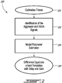
- the identification step also referred to as calibration sub-method 200, illustrated in Figure 2 , consists in finding the mathematical relation between a given aggressor signal and its victims. In order to do so, a plurality of aggressor signals with varying magnitude are generated on the photodiodes of the sensor. These are referred to as calibration traces 201. They are used to identify 202 the photodiodes in which perturbations are induced. Once the aggressors and their victims are identified, the parameters of a model 204 that predicts the shape of the crosstalk generated by each aggressor in each victim is determined. These models are used to predict the shapes of the crosstalk signals generated by a given aggressor during the operation of sensor in order to at least attenuate the crosstalk present in its victims. The prediction model can take several forms, but difference equations or configurable templates are typically established 205.
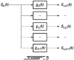
- the relation between an aggressor signal and its victims can be described by a difference equation such as a linear time-invariant discrete equation, as illustrated in Figure 3 , where k is the trace samples, i is the aggressor photosensitive element, j is the victim photosensitive element, s a,i (k) is the aggressor signal in the photosensitive element i and s v,i,j is the perturbation induced by the aggressor i in the photosensitive element j.
- a,i (k) is the aggressor signal in the photosensitive element i
- s v,i,j is the perturbation induced by the aggressor i in the photosensitive element j.
- N is the order of the difference equation
- b and a are
- the coefficients of the difference equation describing the shapes of the victims with respect to an aggressor signal are determined using experimental data. This process consists in finding the coefficients of Eq. 1 that minimize the squared difference between the victim signal predicted from the aggressor with the difference equation and the measured victim signal over several traces. The following steps are performed in order to determine the coefficients of the difference equation.
- An aggressor signal i is created in a given photodiode element of the sensor while adjacent photodiodes are obstructed. Several traces are captured while varying the amplitude of the aggressor signal.
- the 1 th measured aggressor signal is denoted s ⁇ j (l, k).
- the 1 th measured victim signal is denoted s ⁇ i,j (l, k).
- an aggressor signal does not affect a given photosensitivity element in its neighborhood. In that case, the coefficients of the difference equation describing the relation between these elements are set to zero.
- the relation between the aggressor and its victims cannot be expressed accurately using a difference equation.
- the phenomena causing the crosstalk may be too complex to be modelled using a simple linear time-invariant model.
- the number of difference-equation coefficients required to model the crosstalk is too high to allow a real-time implementation of the solution.
- the shape of the crosstalk signal is predicted using a template weighted by the maximum amplitude of the aggressor signal and aligned with the location of the maximum peak of the aggressor.
- the minimum value of the cost function used in the optimization problem presented in Eq. 2 is monitored and compared to a predefined threshold.
- the minimum value of the cost function is above the predefined threshold, the difference equation is considered not to be a reliable representation of the phenomenon occurring between the aggressor and the victims and a predefined template is used for modeling the relation between the aggressor and its victims. The following steps are performed to generate the noise template.
- An aggressor signal i is created in a given photodiode element of the sensor and F traces are captured while varying the amplitude of the aggressor signal.
- the 1 th measured aggressor signal is denoted s ⁇ i (l,k).
- the 1 th measured victim signal is denoted s ⁇ i,j (l,k).
- m i is the position of the maximum peak of the aggressor i evaluated using a quadratic interpolation of the aggressor summit.
- the difference equations or the templates describing the relations between the aggressor and the victim are established 205, they are used to remove or at least attenuate the extrinsic static noise in the traces of the victims using the operation sub-method 210 illustrated in Figure 4 .
- a plurality of operation traces 211 are generated on the photodiodes of the sensor. The shapes of the operation traces 211 are determined by the presence of objects in the field-of-view of the sensor.
- the attenuation/removal of the extrinsic static noise comprises the following steps.
- the first step 212 consists in detecting pulses in the trace of each photodiode element, as described below.
- the second step 214 which is optional, consists in completing the summit of any saturated pulses to remove the discontinuities in the trace of the aggressor, if any.
- the third step 216 consists in determining which ones of the detected pulses have an amplitude sufficient to generate crosstalk (that is, to be an aggressor) in other photodiode elements. If the amplitude is considered sufficient to generate crosstalk 218, the last step consists 220 in attenuating/removing the crosstalk generated by each aggressor in the traces of each of its victims using either the difference equation or the crosstalk template established 205 during calibration.
- the cleaned photodiode traces or signals are outputted 221.
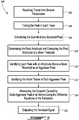
- FIG. 5 illustrates one embodiment of a method 300 for at least partially removing extrinsic static noise in a signal obtained by an optical time-of-flight sensor using full-waveform analysis.
- the first step 302 consists in concurrently receiving the traces from the photosensitive elements.
- the peaks in each acquired trace are localized at step 304.
- the summits of the saturated peaks, if any, are optionally completed using at step 306.
- the values of the peaks found at the previous step are compared to a given threshold.
- the peaks with a maximum value higher than a given threshold are identified as aggressor peaks at step 310.
- the victim traces of each aggressor peak are identified at step 312.
- the crosstalk caused by each aggressor signal is then removed or at least attenuated from its victim traces at step 314, thereby obtaining the denoised traces.
- the denoised signal is outputted at step 316.
- each detected pulse i is characterized by the following parameters, namely an amplitude a i , the index of their right side limit r i , the index of the left side limit l i , and the index of their maximum peak m i .
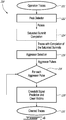
- the peak detection method 320 is described in Figure 7 .
- This method can be seen as a state machine that finds the local maxima in the trace. Once located and characterized by the parameters presented above, each local maximum corresponds to a peak. The peaks of high amplitude are considered as aggressors.
- the method starts at 322 by assuming that the first sample is potentially the left side limit of the first peak in the trace. The method also assumes that the first sample is located on the rising edge of this peak. Thereafter, the method verifies each sample of the trace one after the other until they have all been checked 340. For each sample, the algorithm checks if one of the following three cases occurs.
- Case 1 The value of the previous sample is greater than the value of the current sample 326, the states are updated 328 and the previous sample is located on the rising edge of current peak 342. The previous sample is then a local maximum. The algorithm then assigns the maximum index and the amplitude of the current peak 344 and loops back to verifying the next sample 324, after having updated the index of the sample 338.
- the left and right side limits of each detected pulse are readjusted so that they do not exceed a predefined distance (in samples) from the index of the pulse maximum. As described below, this consideration may help reducing the computational burden of the crosstalk removal algorithm.
- the crosstalk signals are directly linked to the aggressor signals.
- the aggressor signal When the aggressor signal is saturated, the response of the difference equation is erroneous or the position of its maximum peak is uncertain which creates difficulties in aligning the crosstalk template.
- the interpolation of the summit of the saturated peak allows mimicking the shape of the equivalent non-saturated signal and hence obtaining a more accurate prediction of the crosstalk signal.
- Figure 8 illustrates a saturated summit with its interpolated summit completion.
- the polynomial equation passes through three points: the non-saturated sample before the saturation plateau, the non-saturated sample after the saturation plateau and a sample centered on the saturated plateau with a value corresponding to the amplitude of the pulse if it was not saturated (3 constraints).
- the expected amplitude of the saturated pulse is computed using an empirical equation that depends on the width of the saturation plateau. This equation is built with experimental data taken as follows. The light source of the sensor is set to its maximum intensity in order to obtain a strongly saturated signal from a highly reflective target installed close to the sensor. The width of the saturation is computed. The intensity of the light source is decreased until the saturation disappears.
- the amplitude of the saturated pulse can be extrapolated using a simple product rule. This exercise is repeated for many widths of the saturation plateau in order to formulate the empirical equation (polynomial equation or piecewise function) that relates the amplitude of the saturated pulse as a function of the width of the saturation plateau.
- the transition between the non-saturated samples of the pulse and the interpolated sample should be smooth.
- the derivative of the polynomial equation with respect to k should be equal to the derivative of the trace at the samples before and after the saturation plateau (2 constraints).
- the aggressor selection function simply determines if a given pulse can generate crosstalk based on its amplitude. A pulse is considered an aggressor when its amplitude is greater that a predefined threshold. If the pulse of a given signal is below the predefined threshold, then the given signal is not considered an aggressor.
- the first technique consists in defining the difference equations describing the shape of the crosstalk generated on the victims as a function of the aggressor signal.
- the second technique consists in defining a template weighted and aligned using the amplitude and the position of the maximum peak of the aggressor signal.
- the calibration method predicts the shape of the crosstalk in the victims by using the difference equations or the crosstalk templates.
- the prediction of the crosstalk signal generated by an aggressor on a given segment using the difference equation simply consists in computing the responses of the difference equations to the aggressor signal.
- the prediction of the crosstalk signals using templates is more complex.
- the template is scaled by a factor proportional to the aggressor amplitude.
- the template is then aligned with the position of the maximum peak of the aggressor.
- An interpolation technique may be used to increase the performance of the crosstalk attenuation.
- the amplitude factor as well as the number of sample shift or subsample shift (for more precision) of the template have been identified during calibration.
- the predicted shapes of the crosstalk generated by an aggressor in the victim signals are subtracted. To speed-up the computation time, it is assumed that the aggressor only affects its victims between its left and right side index limits determined by the peak detector algorithm presented above.
- the overall computer-implemented method which includes the identification/calibration sub-method and the operation sub-method can be summarized as follows. It is a method for at least partially removing extrinsic static noise from full-waveform data obtained using an optical time-of-flight sensor.
- the sensor has a plurality of synchronized photosensitive elements, at least some are positioned in proximity thereby allowing electromagnetic crosstalk caused by an aggressor photosensitive element to affect at least one victim photosensitive element.
- the method includes the following steps:
- the aggressor calibration traces and the victim calibration traces are obtained in a controlled environment wherein an amplitude of a calibration peak of the aggressor calibration traces is varied and no object is present in a field-of-view of the victim photosensitive element(s).
- the predetermined threshold corresponds to a minimum amplitude of the calibration peak of the aggressor calibration traces at which the electromagnetic crosstalk is present in the plurality of victim calibration traces.
- the operation trace is obtained in an uncontrolled environment wherein a shape of a detection peak of the operation trace is determined by a presence of an object in a field-of-view of the optical time-of-flight sensor during normal operation, the shape including an amplitude and a location of the detection peak.
- the method further comprises identifying the operation trace as being saturated and interpolating a peak value of the operation trace identified as saturated. In one embodiment, interpolating the peak value is performed using a fourth-order polynomial equation.
- the mathematical representation is a difference equation, wherein coefficients of the difference equation describe a shape of the plurality of victim calibration traces with respect to the plurality of aggressor calibration traces for each victim photosensitive element.
- finding the mathematical representation includes determining a cost function for the difference equation; calculating the coefficients by minimizing the cost function and the minimal value of the cost function; and comparing the minimal value of the cost function to a cost threshold.
- the difference equation is a linear time-invariant discrete equation.
- calculating the coefficients of the difference equation is performed using an optimization method.
- the optimization method comprises a Levenberg-Marquardt method.
- the mathematical representation is determined using a template.
- the template is weighted by the amplitude of the detection peak and aligned with a location of the detection peak.
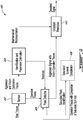
- the methods described above can be embodied as a system, an example of which is shown in Figure 9 .
- the system 400 is for at least partially removing extrinsic static noise from full-waveform data obtained using an optical time-of-flight sensor.
- the optical time-of-flight sensor 402 has a plurality of synchronized photosensitive elements. At least some of the synchronized photosensitive elements are positioned in proximity thereby allowing electromagnetic crosstalk caused by an aggressor photosensitive element to affect at least one victim photosensitive element.
- the system comprises an identification and parameter estimation unit 404, a peak detection unit 406, a crosstalk prediction unit 410 and an optional saturated summit completion unit 408.
- the identification and parameter estimation unit 404 receives the aggressor and victim calibration traces from the sensor 402 and outputs the mathematical representation and the predetermined threshold for the peak detection.
- the peak detection unit 406 receives the operation traces from the sensor 402 and the predetermined threshold from the identification and parameter estimation unit 404 and outputs the aggressor signals whose peaks are greater than the threshold with their victim operation traces.
- the crosstalk prediction unit 410 receives the mathematical representation from the identification and parameter estimation unit 404 and the aggressor signal with its victim operation traces from the peak detection unit 406 to predict and remove, at least partly, the extrinsic static noise generated by the aggressor signal on each victim operation trace. A denoised signal is outputted by the crosstalk prediction unit 410.
- an optional saturated summit completion unit 408 is provided for interpolating a peak value of the operation trace identified as saturated by the peak detection unit 406.
- the crosstalk prediction unit 410 carries out its prediction and removal for all operation peaks detected by the peak detection unit 406 in each aggressor operation traces and for all aggressor traces.
- a trace from one photodiode of an array can be, simultaneously, an aggressor to one or many other photodiodes and a victim of a plurality of other photodiodes acting as aggressors and all crosstalk contributions are addressed by the crosstalk prediction unit 410 to ensure that the system has considered all crosstalk sources prior to outputting the denoised signal.
- the identification and parameter estimation unit 404, the peak detection unit 406, the optional saturated summit completion 408 and the crosstalk prediction unit 410 are provided by at least one processing unit configured for executing their respective method steps. Memories and communications means are provided as required.
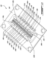
- FIG 10 shows an example setup 500 in which a photodiode array chip 502 is provided on a PCB 504.
- the chip 502 includes a plurality of photodiodes 506a to 506p, collectively referred to as photodiode array 506 having photodiodes 506x.
- Each photodiode 506x of the array is connected by a wire 508x to a PCB track 510x.
- Adjacent photodiodes are typically not connected to adjacent PCB tracks.
- photodiode 506c is adjacent to photodiode 506b and photodiode 506d.
- Photodiode 506c is connected by wire 508c to PCB track 510c.
- PCB tracks 510a and 510e are adjacent to PBC track 510b. If photodiode 506c is determined to be an aggressor because of the amplitude of its operation trace, it will usually create crosstalk, or extrinsic static noise, on the signals of its adjacent photodiodes 506b and 506d (its immediate neighbors) and on the signals of photodiodes 506a and 506e which have adjacent PCB tracks. The victims of photodiode 506c, when it is considered an aggressor, will therefore include neighboring photodiodes 506a, 506b, 506d and 506e, which are all located in proximity to photodiode 506c.
- adjacent wire bound crosstalk Crosstalk between adjacent Printed Circuit Board (PCB) tracks, referred to as adjacent wire bound crosstalk, is one of the most common problems observed with sensors using photodiode arrays. This type of crosstalk is dependent on the PCB design.
- the aggressor signal is the source of the EMF which radiates and contaminates surrounding tracks (victims).
- the victims of photodiode 506c, when it is considered an aggressor, due to adjacent wire bound crosstalk will therefore include photodiodes 506a and 506e.
- the first step consists in generating a signal on the aggressor photodiode while no object is present in the field of view of the victims.
- One way of controlling that no object is present in the field of view of the victim photodiodes is to mask or cover the photosensitive areas of the potential victims.
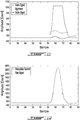
- Example generated signals are illustrated in Figure 11 .
- the amplitude of the signal aggressor is then varied to ensure that only the amplitude of the victim varies as a function of the aggressor amplitude. In other words, there exists a static gain between the aggressor and victim shapes.
- the wide dynamic range of signal exceeds the input voltage range of the ADC.
- the signal is truncated at the maximum value that the ADC can convert.
- the saturated completion summit function is used to interpolate the summit of the saturated aggressor pulse in order to use all of the available signal range in the optimization algorithm, as illustrated in Figure 12 .
- the value of the arrival function cost is lower than a convergence threshold, which means that the identified difference equation of the IIR filter adequately describes the shape of the crosstalk signal as a function of the aggressor pulse.
- Crosstalk generated between adjacent photocells or photosensitive elements is now analyzed. This type of crosstalk is caused by results of electro-magnetic interferences occurring inside the Positive Intrinsic Negative (PIN) diode.
- PIN Positive Intrinsic Negative
- the victims of photodiode 506c, when it is considered an aggressor, due to the proximity of the cells will therefore include photodiodes 506b and 506d.
- the first step consists in generating an aggressor in a given photocell while adjacent photodiodes are masked in order to observe only the shape and the amplitude of the crosstalk signal.
- the amplitude of the signal aggressor is then varied on its entire range.
- the saturated completion summit function is used to interpolate the summit when the pulses are saturated.
- the number of difference equation coefficients is set to 3.
- the value of the function cost is never lower than the predefined threshold. Consequently, one concludes that the transfer function is too complex to be modelled using a simple time-invariant model or that the number of coefficients of the difference equation required to model the phenomena is too high.
- An adjacent-photocell crosstalk signal depends on the characteristics and structure of the photodiode array. Due to single cathode wire bounding, also known as common cathode, the current (I T ) through the cathode is the sum of the currents through each anode (I 1 ...I 6 ). An example setup is illustrated in Figure 16 . When several photodiodes are traversed by a strong signal, the total current through the photodiode creates a perturbation on the voltage of the capacitors (Uc) which affects the photodiodes.
- the first step is to generate an aggressor signal in a given photodiode while there is no object present in the field of view of the other photodiodes in order to determine which photodiode will be affected by the single cathode wire bounding crosstalk.
- One way to achieve this controlled environment is to mask the other photodiodes.
- Figure 17 illustrates the photodiode signals affected by single cathode wire bounding crosstalk. Typically, single cathode wire bounding causes one aggressor to affect the other photodiodes sharing its cathode.
- the amplitude of the aggressor signal is varied on the entire possible range.
- the saturated completion summit function is used to interpolate the summit when the pulses are saturated.
- the number of difference equation coefficients is set to 3.
- the value of the function cost is never lower than a threshold.
- T is the adjacent photocell crosstalk template
- d is the delay between the raw signal and the template.
Landscapes
- Engineering & Computer Science (AREA)
- Physics & Mathematics (AREA)
- General Physics & Mathematics (AREA)
- Radar, Positioning & Navigation (AREA)
- Remote Sensing (AREA)
- Computer Networks & Wireless Communication (AREA)
- Electromagnetism (AREA)
- Photometry And Measurement Of Optical Pulse Characteristics (AREA)
- Materials For Photolithography (AREA)
- Optical Radar Systems And Details Thereof (AREA)
- Noise Elimination (AREA)
- Length Measuring Devices By Optical Means (AREA)
Claims (17)
- Computer-implementiertes Verfahren zum zumindest teilweisen Entfernen von extrinsischem statischem Rauschen aus Full-Waveform-Daten, die unter Verwendung eines optischen Laufzeit- (Time-of-Flight-)sensors gewonnen werden, der eine Mehrzahl von synchronisierten lichtempfindlichen Elementen aufweist, wobei zumindest einige der synchronisierten lichtempfindlichen Elemente nahe beieinander positioniert sind, wodurch zugelassen wird, dass sich elektromagnetisches Nebensprechen, das von einem lichtempfindlichen Aggressorelement der Mehrzahl verursacht wird, zumindest auf ein lichtempfindliches Opferelement der Mehrzahl auswirkt, wobei das computerimplementierte Verfahren die Verwendung mindestens einer Verarbeitungseinheit für Folgendes umfasst:Empfangen einer Mehrzahl von Aggressorkalibrierungsspuren von dem lichtempfindlichen Aggressorelement und einer Mehrzahl von Opferkalibrierungsspuren von dem mindestens einen lichtempfindlichen Opferelement, wobei die Aggressorkalibrierungsspuren und die Opferkalibrierungsspuren in einer kontrollierten Umgebung gewonnen werden, wobei eine Amplitude eines Kalibrierungshöchstwertes der Aggressorkalibrierungsspuren variiert und in einem Sichtfeld des mindestens einen lichtempfindlichen Opferelements kein Objekt vorhanden ist,Finden einer mathematischen Darstellung des elektromagnetischen Nebensprechens, das in der Mehrzahl von Opferkalibrierungsspuren vorhanden ist, für jedes des mindestens einen lichtempfindlichen Opferelements unter Verwendung der Aggressorkalibrierungsspuren und der Opferkalibrierungsspuren,Bestimmen eines festgelegten Schwellenwertes für jedes des mindestens einen lichtempfindlichen Opferelements unter Verwendung der Aggressorkalibrierungsspuren und der Opferkalibrierungsspuren, wobei der festgelegte Schwellenwert einer minimalen Amplitude des Kalibrierungshöchstwertes der Aggressorkalibrierungsspuren entspricht, bei der das elektromagnetische Nebensprechen in der Mehrzahl von Opferkalibrierungsspuren vorhanden ist,Empfangen einer Betriebsspur von dem lichtempfindlichen Aggressorelement, wobei die Betriebsspur in einer unkontrollierten Umgebung gewonnen wird, wobei eine Form eines Detektionshöchstwertes der Betriebsspur anhand des Vorhandenseins eines Objektes in einem Sichtfeld des optischen Laufzeitsensors während des normalen Betriebs bestimmt wird, wobei die Form eine Amplitude und eine Position des Detektionshöchstwertes beinhaltet,Vergleichen der Amplitude des Detektionshöchstwertes der Betriebsspur mit dem festgelegten Schwellenwert und Identifizieren der Betriebsspur als ein Aggressorsignal, das von dem lichtempfindlichen Aggressorelement erstellt wird, wenn die Amplitude des Detektionshöchstwertes größer als der festgelegte Schwellenwert ist,Empfangen mindestens einer synchronisierten Opferbetriebsspur von dem mindestens einen lichtempfindlichen Opferelement,Vorhersagen des extrinsischen statischen Rauschens, das durch das Aggressorsignal auf der mindestens einen synchronisierten Opferbetriebsspur erzeugt wird, unter Verwendung der mathematischen Darstellung für jedes des mindestens einen lichtempfindlichen Opferelements, um ein Vorhergesagtes-Nebensprechen-Signal zu erzeugen,Entfernen des Vorhergesagtes-Nebensprechen-Signals aus der synchronisierten Opferbetriebsspur, wodurch mindestens ein entrauschtes Signal gewonnen wird, undAusgeben des mindestens einen entrauschten Signals.
- Computer-implementiertes Verfahren nach Anspruch 1,
ferner das Identifizieren der Betriebsspur als gesättigt umfassend und
wobei das Vergleichen der Amplitude des Detektionshöchstwertes das Interpolieren eines Höchstwertes der als gesättigt identifizierten Betriebsspur umfasst. - Computer-implementiertes Verfahren nach Anspruch 2, wobei das Interpolieren des Höchstwertes unter Verwendung einer Polynomgleichung vierten Grades durchgeführt wird.
- Computer-implementiertes Verfahren nach einem der Ansprüche 1 bis 3, wobei die mathematische Darstellung eine Differenzgleichung ist, wobei Koeffizienten der Differenzgleichung eine Form der Mehrzahl von Opferkalibrierungsspuren in Bezug auf die Mehrzahl von Aggressorkalibrierungsspuren für jedes des mindestens einen lichtempfindlichen Opferelements beschreiben.
- Computer-implementiertes Verfahren nach Anspruch 4, wobei das Finden der mathematischen Darstellung Folgendes beinhaltet:Bestimmen einer Kostenfunktion für die Differenzgleichung,Berechnen der Koeffizienten durch Minimieren der Kostenfunktion und des Minimalwertes der Kostenfunktion undVergleichen des Minimalwertes der Kostenfunktion mit einem Kostenschwellenwert.
- Computer-implementiertes Verfahren nach einem der Ansprüche 4 und 5, wobei die Differenzgleichung eine lineare zeitinvariante diskrete Gleichung ist.
- Computer-implementiertes Verfahren nach einem der Ansprüche 5 bis 6, wobei die Berechnung der Koeffizienten der Differenzgleichung unter Verwendung eines Optimierungsverfahrens durchgeführt wird.
- Computer-implementiertes Verfahren nach Anspruch 7, wobei das Optimierungsverfahren ein Levenberg-Marquardt-Verfahren umfasst.
- Computer-implementiertes Verfahren nach einem der Ansprüche 5 bis 8, ferner das Bestimmen der mathematischen Darstellung unter Verwendung einer Vorlage, wenn der Minimalwert der Kostenfunktion oberhalb des Kostenschwellenwertes liegt, umfassend.
- Computer-implementiertes Verfahren nach einem der Ansprüche 1 bis 3, wobei die mathematische Darstellung eine Vorlage ist, wobei die Vorlage durch die Amplitude des Detektionshöchstwertes gewichtet und mit einer Position des Detektionshöchstwertes abgeglichen ist.
- System zum zumindest teilweisen Entfernen von extrinsischem statischem Rauschen aus Full-Waveform-Daten, die unter Verwendung eines optischen Laufzeit-(Time-of-Flight-)sensors gewonnen werden, der eine Mehrzahl von synchronisierten lichtempfindlichen Elementen aufweist, wobei zumindest einige der synchronisierten lichtempfindlichen Elemente nahe beieinander positioniert sind, wodurch zugelassen wird, dass sich elektromagnetisches Nebensprechen, das von einem lichtempfindlichen Aggressorelement der Mehrzahl verursacht wird, zumindest auf ein lichtempfindliches Opferelement der Mehrzahl auswirkt, wobei das System Folgendes umfasst:eine Identifikations- und Parameterschätzeinheit zumEmpfangen einer Mehrzahl von Aggressorkalibrierungsspuren von dem lichtempfindlichen Aggressorelement und einer Mehrzahl von Opferkalibrierungsspuren von dem mindestens einen lichtempfindlichen Opferelement, wobei die Aggressorkalibrierungsspuren und die Opferkalibrierungsspuren in einer kontrollierten Umgebung gewonnen werden, wobei eine Amplitude eines Kalibrierungshöchstwertes der Aggressorkalibrierungsspuren variiert und in einem Sichtfeld des mindestens einen lichtempfindlichen Opferelements kein Objekt vorhanden ist,Finden einer mathematischen Darstellung des elektromagnetischen Nebensprechens, das in der Mehrzahl von Opferkalibrierungsspuren vorhanden ist, für jedes des mindestens einen lichtempfindlichen Opferelements unter Verwendung der Aggressorkalibrierungsspuren und der Opferkalibrierungsspuren,Bestimmen eines festgelegten Schwellenwertes für jedes des mindestens einen lichtempfindlichen Opferelements unter Verwendung der Aggressorkalibrierungsspuren und der Opferkalibrierungsspuren, wobei der festgelegte Schwellenwert einer minimalen Amplitude des Kalibrierungshöchstwertes der Aggressorkalibrierungsspuren entspricht, bei der das elektromagnetische Nebensprechen in der Mehrzahl von Opferkalibrierungsspuren vorhanden ist,eine Höchstwertdetektionseinheit zumEmpfangen einer Betriebsspur von dem lichtempfindlichen Aggressorelement, wobei die Betriebsspur in einer unkontrollierten Umgebung gewonnen wird, wobei eine Form eines Detektionshöchstwertes der Betriebsspur anhand des Vorhandenseins eines Objektes in einem Sichtfeld des optischen Laufzeitsensors während des normalen Betriebs bestimmt wird, wobei die Form eine Amplitude und eine Position des Detektionshöchstwertes beinhaltet,Vergleichen der Amplitude des Detektionshöchstwertes der Betriebsspur mit dem festgelegten Schwellenwert und Identifizieren der Betriebsspur als ein Aggressorsignal, das von dem lichtempfindlichen Aggressorelement erstellt wird, wenn die Amplitude des Detektionshöchstwertes größer als der festgelegte Schwellenwert ist,Empfangen mindestens einer synchronisierten Opferbetriebsspur von dem mindestens einen lichtempfindlichen Opferelement,eine Nebensprechen-Vorhersageeinheit zumVorhersagen des extrinsischen statischen Rauschens, das durch das Aggressorsignal auf der mindestens einen synchronisierten Opferbetriebsspur erzeugt wird, unter Verwendung der mathematischen Darstellung für jedes des mindestens einen lichtempfindlichen Opferelements, um ein Vorhergesagtes-Nebensprechen-Signal zu erzeugen,Entfernen des Vorhergesagtes-Nebensprechen-Signals aus der synchronisierten Opferbetriebsspur, wodurch mindestens ein entrauschtes Signal gewonnen wird, undAusgeben des mindestens einen entrauschten Signals,wobei die Identifikations- und Parameterschätzeinheit, die Höchstwertdetektionseinheit und die Nebensprechen-Vorhersageeinheit durch mindestens eine Verarbeitungseinheit bereitgestellt werden.
- System nach Anspruch 11, ferner eine Gesättigter-Scheitelpunkt-Abschlusseinheit zum Identifizieren der Betriebsspur als gesättigt und zum Interpolieren eines Höchstwertes der als gesättigt identifizierten Betriebsspur umfassend.
- System nach einem der Ansprüche 11 bis 12, wobei die mathematische Darstellung eine Differenzgleichung ist, wobei Koeffizienten der Differenzgleichung eine Form der Mehrzahl von Opferkalibrierungsspuren in Bezug auf die Mehrzahl von Aggressorkalibrierungsspuren für jedes des mindestens einen lichtempfindlichen Opferelements beschreiben.
- System nach Anspruch 13, wobei die Differenzgleichung eine lineare zeitinvariante diskrete Gleichung ist.
- System nach einem der Ansprüche 13 und 14, wobei die Identifikations- und Parameterschätzeinheit ferner gestaltet ist zum:Bestimmen einer Kostenfunktion für die Differenzgleichung,Berechnen der Koeffizienten durch Minimieren der Kostenfunktion und des Minimalwertes der Kostenfunktion undVergleichen des Minimalwertes der Kostenfunktion mit einem Kostenschwellenwert.
- System nach Anspruch 15, wobei die Identifikations- und Parameterschätzeinheit die mathematische Darstellung unter Verwendung einer Vorlage bestimmt, wenn der Minimalwert der Kostenfunktion oberhalb des Kostenschwellenwertes liegt.
- System nach einem der Ansprüche 11 bis 14, wobei die Identifikations- und Parameterschätzeinheit die mathematische Darstellung unter Verwendung einer Vorlage bestimmt, wobei die Vorlage durch die Amplitude des Detektionshöchstwertes gewichtet und mit einer Position des Detektionshöchstwertes abgeglichen ist.
Applications Claiming Priority (2)
| Application Number | Priority Date | Filing Date | Title |
|---|---|---|---|
| US201562271727P | 2015-12-28 | 2015-12-28 | |
| PCT/IB2016/057985 WO2017115258A1 (en) | 2015-12-28 | 2016-12-23 | Extrinsic static noise characterization and removal |
Publications (3)
| Publication Number | Publication Date |
|---|---|
| EP3397985A1 EP3397985A1 (de) | 2018-11-07 |
| EP3397985A4 EP3397985A4 (de) | 2019-08-14 |
| EP3397985B1 true EP3397985B1 (de) | 2020-08-26 |
Family
ID=59224690
Family Applications (2)
| Application Number | Title | Priority Date | Filing Date |
|---|---|---|---|
| EP16881362.4A Pending EP3397986A4 (de) | 2015-12-28 | 2016-12-22 | Statische intrinsische rauschcharakterisierung und -beseitigung |
| EP16881364.0A Active EP3397985B1 (de) | 2015-12-28 | 2016-12-23 | Extrinsische statische rauschcharakterisierung und beseitigung |
Family Applications Before (1)
| Application Number | Title | Priority Date | Filing Date |
|---|---|---|---|
| EP16881362.4A Pending EP3397986A4 (de) | 2015-12-28 | 2016-12-22 | Statische intrinsische rauschcharakterisierung und -beseitigung |
Country Status (4)
| Country | Link |
|---|---|
| US (2) | US11035937B2 (de) |
| EP (2) | EP3397986A4 (de) |
| CA (2) | CA3009722C (de) |
| WO (2) | WO2017115247A1 (de) |
Families Citing this family (17)
| Publication number | Priority date | Publication date | Assignee | Title |
|---|---|---|---|---|
| SE1750159A1 (sv) * | 2017-02-17 | 2018-08-18 | Fingerprint Cards Ab | Cancelling out impairment data in fingerprint images |
| EP3367668B1 (de) * | 2017-02-24 | 2019-10-02 | Melexis Technologies NV | Rauschverminderung in abtast- und haltesystemen |
| EP3460509B1 (de) * | 2017-09-22 | 2024-12-11 | ams AG | Verfahren zur kalibrierung eines flugzeitsystems sowie flugzeitsystem |
| US11353555B2 (en) | 2017-11-01 | 2022-06-07 | Luminar, Llc | Detector quench circuit for lidar system comprising a discrete transistor to draw a quench current to enable a drop in a reverse bias voltage applied to an avalanche photodiode |
| JP7109906B2 (ja) * | 2017-11-14 | 2022-08-01 | シャープ株式会社 | 光センサ及び電子機器 |
| US10884101B2 (en) * | 2018-01-30 | 2021-01-05 | Motorola Mobility Llc | Crosstalk detection and compensation |
| US11100194B2 (en) | 2018-06-01 | 2021-08-24 | Blackberry Limited | Method and system for cargo sensing estimation |
| US11500074B2 (en) * | 2018-12-14 | 2022-11-15 | Beijing Voyager Technology Co., Ltd. | Light detection and ranging (LiDAR) with pulse equalizer |
| WO2020201452A1 (en) * | 2019-04-02 | 2020-10-08 | Ams International Ag | Method of measuring optical crosstalk in a time of flight sensor and corresponding time of flight sensor |
| WO2020206602A1 (zh) * | 2019-04-09 | 2020-10-15 | 华为技术有限公司 | 一种测距方法、装置及设备 |
| JP2021021597A (ja) * | 2019-07-25 | 2021-02-18 | 株式会社東芝 | 距離計測装置、及び距離計測方法 |
| TWI734252B (zh) * | 2019-11-08 | 2021-07-21 | 立積電子股份有限公司 | 雷達及雷達回波訊號的背景成分更新方法 |
| EP3862782A1 (de) * | 2020-02-04 | 2021-08-11 | Infineon Technologies AG | Vorrichtung und verfahren zur korrektur eines eingangssignals |
| US11228368B1 (en) | 2020-09-03 | 2022-01-18 | Microsoft Technology Licensing, Llc | Characterization of inter-channel crosstalk in an optical network |
| JP2022117173A (ja) * | 2021-01-29 | 2022-08-10 | 株式会社トプコン | 光波距離計および距離算出方法 |
| JP7623873B2 (ja) * | 2021-03-30 | 2025-01-29 | 浜松ホトニクス株式会社 | 光検出回路及び計測装置 |
| US12566908B2 (en) | 2022-09-22 | 2026-03-03 | International Business Machines Corporation | Single corner mixed voltage noise impact on function analysis |
Family Cites Families (9)
| Publication number | Priority date | Publication date | Assignee | Title |
|---|---|---|---|---|
| US5892575A (en) * | 1996-05-10 | 1999-04-06 | Massachusetts Institute Of Technology | Method and apparatus for imaging a scene using a light detector operating in non-linear geiger-mode |
| US20060164533A1 (en) * | 2002-08-27 | 2006-07-27 | E-Phocus, Inc | Electronic image sensor |
| TWI333542B (en) | 2007-06-25 | 2010-11-21 | Asia Optical Co Inc | Laser rangefinder and method for digital signal processing thereof |
| US7640122B2 (en) | 2007-11-07 | 2009-12-29 | Institut National D'optique | Digital signal processing in optical systems used for ranging applications |
| US8643742B2 (en) * | 2010-10-15 | 2014-02-04 | Cisco Technology, Inc. | Crosstalk filter in a digital image processing pipeline |
| DE102010061382B4 (de) | 2010-12-21 | 2019-02-14 | Sick Ag | Optoelektronischer Sensor und Verfahren zur Erfassung und Abstandsbestimmung von Objekten |
| DE102012208308A1 (de) * | 2012-05-18 | 2013-11-21 | Robert Bosch Gmbh | Optisches Entfernungsmessgerät mit Kalibriereinrichtung zum Berücksichtigen von Übersprechen |
| EP3056924B1 (de) * | 2013-10-11 | 2020-01-01 | Mitsubishi Electric Corporation | Lidar-vorrichtung zur windmessung |
| US9772398B2 (en) * | 2014-06-26 | 2017-09-26 | Intersil Americas LLC | Optical proximity sensors with reconfigurable photodiode array |
-
2016
- 2016-12-22 WO PCT/IB2016/057957 patent/WO2017115247A1/en not_active Ceased
- 2016-12-22 CA CA3009722A patent/CA3009722C/en active Active
- 2016-12-22 US US16/066,404 patent/US11035937B2/en active Active
- 2016-12-22 EP EP16881362.4A patent/EP3397986A4/de active Pending
- 2016-12-23 WO PCT/IB2016/057985 patent/WO2017115258A1/en not_active Ceased
- 2016-12-23 EP EP16881364.0A patent/EP3397985B1/de active Active
- 2016-12-23 CA CA3009869A patent/CA3009869C/en active Active
- 2016-12-23 US US16/066,403 patent/US10845471B2/en active Active
Non-Patent Citations (1)
| Title |
|---|
| None * |
Also Published As
| Publication number | Publication date |
|---|---|
| CA3009722C (en) | 2021-01-26 |
| EP3397985A4 (de) | 2019-08-14 |
| US10845471B2 (en) | 2020-11-24 |
| CA3009869A1 (en) | 2017-07-06 |
| US20190011543A1 (en) | 2019-01-10 |
| EP3397985A1 (de) | 2018-11-07 |
| US20190004158A1 (en) | 2019-01-03 |
| WO2017115247A1 (en) | 2017-07-06 |
| EP3397986A1 (de) | 2018-11-07 |
| CA3009722A1 (en) | 2017-07-06 |
| CA3009869C (en) | 2018-11-27 |
| US11035937B2 (en) | 2021-06-15 |
| WO2017115258A1 (en) | 2017-07-06 |
| EP3397986A4 (de) | 2019-08-07 |
Similar Documents
| Publication | Publication Date | Title |
|---|---|---|
| EP3397985B1 (de) | Extrinsische statische rauschcharakterisierung und beseitigung | |
| US12367257B2 (en) | Method and apparatus for processing a histogram output from a detector sensor | |
| CN111868561B (zh) | 使用本底噪声的自适应识别进行有效信号检测 | |
| EP3370080B1 (de) | Bereichs- und parameterextraktion mit verarbeiteten, aus einem flugzeitsensor erzeugten histogrammen parameterextraktion | |
| CN111868560B (zh) | 取决于脉冲类型选择lidar脉冲检测器 | |
| EP3370078B1 (de) | Bereichs- und parameterextraktion mit verarbeiteten, aus einem flugzeitsensor erzeugten histogrammen übersprechungskorrektur | |
| US20220128658A1 (en) | Waveform reconstruction in a time-of-flight sensor | |
| CN113661407A (zh) | 测量飞行时间传感器中的光学串扰的方法和对应的飞行时间传感器 | |
| EP3370079B1 (de) | Bereichs- und parameterextraktion mit verarbeiteten histogrammen, die aus einer flugzeitsensorimpulskorrektur erzeugt sind | |
| CN112789522A (zh) | 一种目标物的反射率计算方法、装置及相关设备 | |
| US7928392B1 (en) | Systems and methods for blind echo cancellation | |
| US20180024184A1 (en) | Method for characterising a soft fault in a cable | |
| EP3370086B1 (de) | Bereichs- und parameterextraktion mit verarbeiteten, aus einer korrektur von flugzeitsensor daten mit pile-up erzeugten histogrammen | |
| JP7312766B2 (ja) | 放射パルス検出器の入力カウントレート推定 | |
| CN117240350A (zh) | 事件检测装置及事件检测方法 | |
| CN119439135A (zh) | 一种测风激光雷达的数据质量控制方法 | |
| Egorov et al. | Estimating the errors of the results of lidar probing of a weakly turbid atmosphere | |
| Bekhtin et al. | Compensation of IR-sensor Fixed Pattern Noise during Point Object Magnitude Recovering | |
| Basden et al. | Low readout noise CCDs in optical interferometry | |
| RU2524349C9 (ru) | Способ обнаружения импульса от цели и измерения его параметров | |
| Anthonys et al. | Signal processing approaches for jitter extraction in Time-of-Flight range imaging cameras | |
| Zhang et al. | Research on echo signal processing method based on single-photon detection | |
| Harnau | Region of Interest-Based Depth Correction and Multipath Interference Mitigation in Time-of-Flight Cameras for Short-Range Automation: development of a Local Filtering Pipeline for Adaptive Region of Interest Detection and Multi-path Interference Reduction | |
| Fasolino et al. | Real-time crosstalk compensation in multizone Time-of-Flight sensors | |
| JPH11133080A (ja) | 電磁妨害波計測装置 |
Legal Events
| Date | Code | Title | Description |
|---|---|---|---|
| STAA | Information on the status of an ep patent application or granted ep patent |
Free format text: STATUS: THE INTERNATIONAL PUBLICATION HAS BEEN MADE |
|
| PUAI | Public reference made under article 153(3) epc to a published international application that has entered the european phase |
Free format text: ORIGINAL CODE: 0009012 |
|
| STAA | Information on the status of an ep patent application or granted ep patent |
Free format text: STATUS: REQUEST FOR EXAMINATION WAS MADE |
|
| 17P | Request for examination filed |
Effective date: 20180725 |
|
| AK | Designated contracting states |
Kind code of ref document: A1 Designated state(s): AL AT BE BG CH CY CZ DE DK EE ES FI FR GB GR HR HU IE IS IT LI LT LU LV MC MK MT NL NO PL PT RO RS SE SI SK SM TR |
|
| AX | Request for extension of the european patent |
Extension state: BA ME |
|
| DAV | Request for validation of the european patent (deleted) | ||
| DAX | Request for extension of the european patent (deleted) | ||
| REG | Reference to a national code |
Ref country code: DE Ref legal event code: R079 Ref document number: 602016042972 Country of ref document: DE Free format text: PREVIOUS MAIN CLASS: G01S0007487000 Ipc: G01S0007497000 |
|
| A4 | Supplementary search report drawn up and despatched |
Effective date: 20190712 |
|
| RIC1 | Information provided on ipc code assigned before grant |
Ipc: G01S 17/10 20060101ALI20190708BHEP Ipc: G01S 7/487 20060101ALI20190708BHEP Ipc: G01S 7/497 20060101AFI20190708BHEP |
|
| GRAP | Despatch of communication of intention to grant a patent |
Free format text: ORIGINAL CODE: EPIDOSNIGR1 |
|
| STAA | Information on the status of an ep patent application or granted ep patent |
Free format text: STATUS: GRANT OF PATENT IS INTENDED |
|
| INTG | Intention to grant announced |
Effective date: 20200305 |
|
| GRAS | Grant fee paid |
Free format text: ORIGINAL CODE: EPIDOSNIGR3 |
|
| GRAA | (expected) grant |
Free format text: ORIGINAL CODE: 0009210 |
|
| STAA | Information on the status of an ep patent application or granted ep patent |
Free format text: STATUS: THE PATENT HAS BEEN GRANTED |
|
| AK | Designated contracting states |
Kind code of ref document: B1 Designated state(s): AL AT BE BG CH CY CZ DE DK EE ES FI FR GB GR HR HU IE IS IT LI LT LU LV MC MK MT NL NO PL PT RO RS SE SI SK SM TR |
|
| REG | Reference to a national code |
Ref country code: GB Ref legal event code: FG4D |
|
| REG | Reference to a national code |
Ref country code: CH Ref legal event code: EP |
|
| REG | Reference to a national code |
Ref country code: AT Ref legal event code: REF Ref document number: 1306883 Country of ref document: AT Kind code of ref document: T Effective date: 20200915 |
|
| REG | Reference to a national code |
Ref country code: IE Ref legal event code: FG4D |
|
| REG | Reference to a national code |
Ref country code: DE Ref legal event code: R096 Ref document number: 602016042972 Country of ref document: DE |
|
| REG | Reference to a national code |
Ref country code: LT Ref legal event code: MG4D |
|
| PG25 | Lapsed in a contracting state [announced via postgrant information from national office to epo] |
Ref country code: NO Free format text: LAPSE BECAUSE OF FAILURE TO SUBMIT A TRANSLATION OF THE DESCRIPTION OR TO PAY THE FEE WITHIN THE PRESCRIBED TIME-LIMIT Effective date: 20201126 Ref country code: BG Free format text: LAPSE BECAUSE OF FAILURE TO SUBMIT A TRANSLATION OF THE DESCRIPTION OR TO PAY THE FEE WITHIN THE PRESCRIBED TIME-LIMIT Effective date: 20201126 Ref country code: GR Free format text: LAPSE BECAUSE OF FAILURE TO SUBMIT A TRANSLATION OF THE DESCRIPTION OR TO PAY THE FEE WITHIN THE PRESCRIBED TIME-LIMIT Effective date: 20201127 Ref country code: LT Free format text: LAPSE BECAUSE OF FAILURE TO SUBMIT A TRANSLATION OF THE DESCRIPTION OR TO PAY THE FEE WITHIN THE PRESCRIBED TIME-LIMIT Effective date: 20200826 Ref country code: SE Free format text: LAPSE BECAUSE OF FAILURE TO SUBMIT A TRANSLATION OF THE DESCRIPTION OR TO PAY THE FEE WITHIN THE PRESCRIBED TIME-LIMIT Effective date: 20200826 Ref country code: HR Free format text: LAPSE BECAUSE OF FAILURE TO SUBMIT A TRANSLATION OF THE DESCRIPTION OR TO PAY THE FEE WITHIN THE PRESCRIBED TIME-LIMIT Effective date: 20200826 Ref country code: PT Free format text: LAPSE BECAUSE OF FAILURE TO SUBMIT A TRANSLATION OF THE DESCRIPTION OR TO PAY THE FEE WITHIN THE PRESCRIBED TIME-LIMIT Effective date: 20201228 Ref country code: FI Free format text: LAPSE BECAUSE OF FAILURE TO SUBMIT A TRANSLATION OF THE DESCRIPTION OR TO PAY THE FEE WITHIN THE PRESCRIBED TIME-LIMIT Effective date: 20200826 |
|
| REG | Reference to a national code |
Ref country code: NL Ref legal event code: MP Effective date: 20200826 |
|
| REG | Reference to a national code |
Ref country code: AT Ref legal event code: MK05 Ref document number: 1306883 Country of ref document: AT Kind code of ref document: T Effective date: 20200826 |
|
| PG25 | Lapsed in a contracting state [announced via postgrant information from national office to epo] |
Ref country code: IS Free format text: LAPSE BECAUSE OF FAILURE TO SUBMIT A TRANSLATION OF THE DESCRIPTION OR TO PAY THE FEE WITHIN THE PRESCRIBED TIME-LIMIT Effective date: 20201226 Ref country code: PL Free format text: LAPSE BECAUSE OF FAILURE TO SUBMIT A TRANSLATION OF THE DESCRIPTION OR TO PAY THE FEE WITHIN THE PRESCRIBED TIME-LIMIT Effective date: 20200826 Ref country code: RS Free format text: LAPSE BECAUSE OF FAILURE TO SUBMIT A TRANSLATION OF THE DESCRIPTION OR TO PAY THE FEE WITHIN THE PRESCRIBED TIME-LIMIT Effective date: 20200826 Ref country code: NL Free format text: LAPSE BECAUSE OF FAILURE TO SUBMIT A TRANSLATION OF THE DESCRIPTION OR TO PAY THE FEE WITHIN THE PRESCRIBED TIME-LIMIT Effective date: 20200826 Ref country code: LV Free format text: LAPSE BECAUSE OF FAILURE TO SUBMIT A TRANSLATION OF THE DESCRIPTION OR TO PAY THE FEE WITHIN THE PRESCRIBED TIME-LIMIT Effective date: 20200826 |
|
| PG25 | Lapsed in a contracting state [announced via postgrant information from national office to epo] |
Ref country code: DK Free format text: LAPSE BECAUSE OF FAILURE TO SUBMIT A TRANSLATION OF THE DESCRIPTION OR TO PAY THE FEE WITHIN THE PRESCRIBED TIME-LIMIT Effective date: 20200826 Ref country code: CZ Free format text: LAPSE BECAUSE OF FAILURE TO SUBMIT A TRANSLATION OF THE DESCRIPTION OR TO PAY THE FEE WITHIN THE PRESCRIBED TIME-LIMIT Effective date: 20200826 Ref country code: RO Free format text: LAPSE BECAUSE OF FAILURE TO SUBMIT A TRANSLATION OF THE DESCRIPTION OR TO PAY THE FEE WITHIN THE PRESCRIBED TIME-LIMIT Effective date: 20200826 Ref country code: SM Free format text: LAPSE BECAUSE OF FAILURE TO SUBMIT A TRANSLATION OF THE DESCRIPTION OR TO PAY THE FEE WITHIN THE PRESCRIBED TIME-LIMIT Effective date: 20200826 Ref country code: EE Free format text: LAPSE BECAUSE OF FAILURE TO SUBMIT A TRANSLATION OF THE DESCRIPTION OR TO PAY THE FEE WITHIN THE PRESCRIBED TIME-LIMIT Effective date: 20200826 |
|
| REG | Reference to a national code |
Ref country code: DE Ref legal event code: R097 Ref document number: 602016042972 Country of ref document: DE |
|
| PG25 | Lapsed in a contracting state [announced via postgrant information from national office to epo] |
Ref country code: AL Free format text: LAPSE BECAUSE OF FAILURE TO SUBMIT A TRANSLATION OF THE DESCRIPTION OR TO PAY THE FEE WITHIN THE PRESCRIBED TIME-LIMIT Effective date: 20200826 Ref country code: AT Free format text: LAPSE BECAUSE OF FAILURE TO SUBMIT A TRANSLATION OF THE DESCRIPTION OR TO PAY THE FEE WITHIN THE PRESCRIBED TIME-LIMIT Effective date: 20200826 Ref country code: ES Free format text: LAPSE BECAUSE OF FAILURE TO SUBMIT A TRANSLATION OF THE DESCRIPTION OR TO PAY THE FEE WITHIN THE PRESCRIBED TIME-LIMIT Effective date: 20200826 |
|
| PG25 | Lapsed in a contracting state [announced via postgrant information from national office to epo] |
Ref country code: SK Free format text: LAPSE BECAUSE OF FAILURE TO SUBMIT A TRANSLATION OF THE DESCRIPTION OR TO PAY THE FEE WITHIN THE PRESCRIBED TIME-LIMIT Effective date: 20200826 |
|
| PLBE | No opposition filed within time limit |
Free format text: ORIGINAL CODE: 0009261 |
|
| STAA | Information on the status of an ep patent application or granted ep patent |
Free format text: STATUS: NO OPPOSITION FILED WITHIN TIME LIMIT |
|
| PG25 | Lapsed in a contracting state [announced via postgrant information from national office to epo] |
Ref country code: IT Free format text: LAPSE BECAUSE OF FAILURE TO SUBMIT A TRANSLATION OF THE DESCRIPTION OR TO PAY THE FEE WITHIN THE PRESCRIBED TIME-LIMIT Effective date: 20200826 |
|
| REG | Reference to a national code |
Ref country code: CH Ref legal event code: PL |
|
| 26N | No opposition filed |
Effective date: 20210527 |
|
| PG25 | Lapsed in a contracting state [announced via postgrant information from national office to epo] |
Ref country code: SI Free format text: LAPSE BECAUSE OF FAILURE TO SUBMIT A TRANSLATION OF THE DESCRIPTION OR TO PAY THE FEE WITHIN THE PRESCRIBED TIME-LIMIT Effective date: 20200826 Ref country code: MC Free format text: LAPSE BECAUSE OF FAILURE TO SUBMIT A TRANSLATION OF THE DESCRIPTION OR TO PAY THE FEE WITHIN THE PRESCRIBED TIME-LIMIT Effective date: 20200826 |
|
| REG | Reference to a national code |
Ref country code: BE Ref legal event code: MM Effective date: 20201231 |
|
| PG25 | Lapsed in a contracting state [announced via postgrant information from national office to epo] |
Ref country code: IE Free format text: LAPSE BECAUSE OF NON-PAYMENT OF DUE FEES Effective date: 20201223 Ref country code: LU Free format text: LAPSE BECAUSE OF NON-PAYMENT OF DUE FEES Effective date: 20201223 |
|
| PG25 | Lapsed in a contracting state [announced via postgrant information from national office to epo] |
Ref country code: LI Free format text: LAPSE BECAUSE OF NON-PAYMENT OF DUE FEES Effective date: 20201231 Ref country code: CH Free format text: LAPSE BECAUSE OF NON-PAYMENT OF DUE FEES Effective date: 20201231 |
|
| PG25 | Lapsed in a contracting state [announced via postgrant information from national office to epo] |
Ref country code: TR Free format text: LAPSE BECAUSE OF FAILURE TO SUBMIT A TRANSLATION OF THE DESCRIPTION OR TO PAY THE FEE WITHIN THE PRESCRIBED TIME-LIMIT Effective date: 20200826 Ref country code: MT Free format text: LAPSE BECAUSE OF FAILURE TO SUBMIT A TRANSLATION OF THE DESCRIPTION OR TO PAY THE FEE WITHIN THE PRESCRIBED TIME-LIMIT Effective date: 20200826 Ref country code: CY Free format text: LAPSE BECAUSE OF FAILURE TO SUBMIT A TRANSLATION OF THE DESCRIPTION OR TO PAY THE FEE WITHIN THE PRESCRIBED TIME-LIMIT Effective date: 20200826 |
|
| PG25 | Lapsed in a contracting state [announced via postgrant information from national office to epo] |
Ref country code: MK Free format text: LAPSE BECAUSE OF FAILURE TO SUBMIT A TRANSLATION OF THE DESCRIPTION OR TO PAY THE FEE WITHIN THE PRESCRIBED TIME-LIMIT Effective date: 20200826 |
|
| PG25 | Lapsed in a contracting state [announced via postgrant information from national office to epo] |
Ref country code: BE Free format text: LAPSE BECAUSE OF NON-PAYMENT OF DUE FEES Effective date: 20201231 |
|
| PGFP | Annual fee paid to national office [announced via postgrant information from national office to epo] |
Ref country code: FR Payment date: 20241227 Year of fee payment: 9 |
|
| PGFP | Annual fee paid to national office [announced via postgrant information from national office to epo] |
Ref country code: DE Payment date: 20250116 Year of fee payment: 9 |
|
| PGFP | Annual fee paid to national office [announced via postgrant information from national office to epo] |
Ref country code: GB Payment date: 20250123 Year of fee payment: 9 |