EP3397502B1 - Secure article comprising a combined image and/or a revelation screen - Google Patents
Secure article comprising a combined image and/or a revelation screen Download PDFInfo
- Publication number
- EP3397502B1 EP3397502B1 EP16822190.1A EP16822190A EP3397502B1 EP 3397502 B1 EP3397502 B1 EP 3397502B1 EP 16822190 A EP16822190 A EP 16822190A EP 3397502 B1 EP3397502 B1 EP 3397502B1
- Authority
- EP
- European Patent Office
- Prior art keywords
- image
- article
- images
- combined image
- screen
- Prior art date
- Legal status (The legal status is an assumption and is not a legal conclusion. Google has not performed a legal analysis and makes no representation as to the accuracy of the status listed.)
- Active
Links
- 239000003086 colorant Substances 0.000 claims description 41
- 239000000758 substrate Substances 0.000 claims description 26
- 230000008859 change Effects 0.000 claims description 25
- 230000000737 periodic effect Effects 0.000 claims description 23
- 238000000034 method Methods 0.000 claims description 13
- 238000006073 displacement reaction Methods 0.000 claims description 7
- 230000001747 exhibiting effect Effects 0.000 claims description 5
- 238000004020 luminiscence type Methods 0.000 claims description 3
- 239000007787 solid Substances 0.000 claims description 2
- 238000007639 printing Methods 0.000 description 17
- 239000000463 material Substances 0.000 description 16
- 238000001465 metallisation Methods 0.000 description 13
- 230000000694 effects Effects 0.000 description 12
- 239000011888 foil Substances 0.000 description 12
- 241001080024 Telles Species 0.000 description 10
- 239000004973 liquid crystal related substance Substances 0.000 description 9
- 239000004986 Cholesteric liquid crystals (ChLC) Substances 0.000 description 8
- 239000000203 mixture Substances 0.000 description 8
- 230000003287 optical effect Effects 0.000 description 8
- -1 polyethylene Polymers 0.000 description 7
- 229910052782 aluminium Inorganic materials 0.000 description 6
- XAGFODPZIPBFFR-UHFFFAOYSA-N aluminium Chemical compound [Al] XAGFODPZIPBFFR-UHFFFAOYSA-N 0.000 description 6
- 239000005020 polyethylene terephthalate Substances 0.000 description 6
- 229920000139 polyethylene terephthalate Polymers 0.000 description 6
- 241001465754 Metazoa Species 0.000 description 5
- 239000004698 Polyethylene Substances 0.000 description 5
- 230000015572 biosynthetic process Effects 0.000 description 5
- 239000000835 fiber Substances 0.000 description 5
- 239000000976 ink Substances 0.000 description 5
- 229920000573 polyethylene Polymers 0.000 description 5
- RYGMFSIKBFXOCR-UHFFFAOYSA-N Copper Chemical compound [Cu] RYGMFSIKBFXOCR-UHFFFAOYSA-N 0.000 description 4
- LYCAIKOWRPUZTN-UHFFFAOYSA-N Ethylene glycol Chemical compound OCCO LYCAIKOWRPUZTN-UHFFFAOYSA-N 0.000 description 4
- 230000008901 benefit Effects 0.000 description 4
- 238000004891 communication Methods 0.000 description 4
- 229910052802 copper Inorganic materials 0.000 description 4
- 239000010949 copper Substances 0.000 description 4
- 238000003475 lamination Methods 0.000 description 4
- 238000004519 manufacturing process Methods 0.000 description 4
- 230000010363 phase shift Effects 0.000 description 4
- 229920000515 polycarbonate Polymers 0.000 description 4
- 239000004417 polycarbonate Substances 0.000 description 4
- 230000005540 biological transmission Effects 0.000 description 3
- 230000000903 blocking effect Effects 0.000 description 3
- 150000001875 compounds Chemical class 0.000 description 3
- 238000001514 detection method Methods 0.000 description 3
- 230000006870 function Effects 0.000 description 3
- 238000007645 offset printing Methods 0.000 description 3
- 230000010287 polarization Effects 0.000 description 3
- 229920000728 polyester Polymers 0.000 description 3
- 230000008569 process Effects 0.000 description 3
- 230000002829 reductive effect Effects 0.000 description 3
- 238000012216 screening Methods 0.000 description 3
- 230000000007 visual effect Effects 0.000 description 3
- 238000012800 visualization Methods 0.000 description 3
- BVKZGUZCCUSVTD-UHFFFAOYSA-L Carbonate Chemical compound [O-]C([O-])=O BVKZGUZCCUSVTD-UHFFFAOYSA-L 0.000 description 2
- 101100501444 Escherichia phage P1 17 gene Proteins 0.000 description 2
- 239000004676 acrylonitrile butadiene styrene Substances 0.000 description 2
- 230000009471 action Effects 0.000 description 2
- 230000003098 cholesteric effect Effects 0.000 description 2
- 239000011248 coating agent Substances 0.000 description 2
- 238000000576 coating method Methods 0.000 description 2
- 238000013500 data storage Methods 0.000 description 2
- 230000005284 excitation Effects 0.000 description 2
- WGCNASOHLSPBMP-UHFFFAOYSA-N hydroxyacetaldehyde Natural products OCC=O WGCNASOHLSPBMP-UHFFFAOYSA-N 0.000 description 2
- 238000005286 illumination Methods 0.000 description 2
- 238000003698 laser cutting Methods 0.000 description 2
- 230000000670 limiting effect Effects 0.000 description 2
- 229910052751 metal Inorganic materials 0.000 description 2
- 239000002184 metal Substances 0.000 description 2
- 150000002739 metals Chemical class 0.000 description 2
- 239000002245 particle Substances 0.000 description 2
- 229920005644 polyethylene terephthalate glycol copolymer Polymers 0.000 description 2
- 229920006254 polymer film Polymers 0.000 description 2
- 239000004814 polyurethane Substances 0.000 description 2
- 239000004800 polyvinyl chloride Substances 0.000 description 2
- 238000012546 transfer Methods 0.000 description 2
- 230000007704 transition Effects 0.000 description 2
- PLXMOAALOJOTIY-FPTXNFDTSA-N Aesculin Natural products OC[C@@H]1[C@@H](O)[C@H](O)[C@@H](O)[C@H](O)[C@H]1Oc2cc3C=CC(=O)Oc3cc2O PLXMOAALOJOTIY-FPTXNFDTSA-N 0.000 description 1
- 101001041010 Conus radiatus Iota-conotoxin RXIA Proteins 0.000 description 1
- 229920000742 Cotton Polymers 0.000 description 1
- 239000004721 Polyphenylene oxide Substances 0.000 description 1
- VYPSYNLAJGMNEJ-UHFFFAOYSA-N Silicium dioxide Chemical compound O=[Si]=O VYPSYNLAJGMNEJ-UHFFFAOYSA-N 0.000 description 1
- 238000005299 abrasion Methods 0.000 description 1
- 239000011149 active material Substances 0.000 description 1
- 238000004026 adhesive bonding Methods 0.000 description 1
- 239000002390 adhesive tape Substances 0.000 description 1
- 125000001931 aliphatic group Chemical group 0.000 description 1
- 239000000956 alloy Substances 0.000 description 1
- 229910045601 alloy Inorganic materials 0.000 description 1
- 238000006243 chemical reaction Methods 0.000 description 1
- 239000008119 colloidal silica Substances 0.000 description 1
- 239000002537 cosmetic Substances 0.000 description 1
- 238000004132 cross linking Methods 0.000 description 1
- 239000013078 crystal Substances 0.000 description 1
- 230000001419 dependent effect Effects 0.000 description 1
- 238000010586 diagram Methods 0.000 description 1
- 229910003460 diamond Inorganic materials 0.000 description 1
- 239000010432 diamond Substances 0.000 description 1
- 239000003814 drug Substances 0.000 description 1
- 229940079593 drug Drugs 0.000 description 1
- 239000003000 extruded plastic Substances 0.000 description 1
- 239000011521 glass Substances 0.000 description 1
- 238000007646 gravure printing Methods 0.000 description 1
- 238000010438 heat treatment Methods 0.000 description 1
- 239000012943 hotmelt Substances 0.000 description 1
- 238000010348 incorporation Methods 0.000 description 1
- 229910052500 inorganic mineral Inorganic materials 0.000 description 1
- 239000002650 laminated plastic Substances 0.000 description 1
- 238000010330 laser marking Methods 0.000 description 1
- 238000007648 laser printing Methods 0.000 description 1
- 238000007644 letterpress printing Methods 0.000 description 1
- 239000007788 liquid Substances 0.000 description 1
- 238000001459 lithography Methods 0.000 description 1
- 230000000873 masking effect Effects 0.000 description 1
- 239000011707 mineral Substances 0.000 description 1
- 239000003921 oil Substances 0.000 description 1
- 238000004806 packaging method and process Methods 0.000 description 1
- 230000036961 partial effect Effects 0.000 description 1
- 230000008447 perception Effects 0.000 description 1
- 238000000206 photolithography Methods 0.000 description 1
- 239000000049 pigment Substances 0.000 description 1
- 229920003023 plastic Polymers 0.000 description 1
- 239000004033 plastic Substances 0.000 description 1
- 229920000570 polyether Polymers 0.000 description 1
- 229920000642 polymer Polymers 0.000 description 1
- 229920000098 polyolefin Polymers 0.000 description 1
- 229920002635 polyurethane Polymers 0.000 description 1
- 230000005855 radiation Effects 0.000 description 1
- 230000002441 reversible effect Effects 0.000 description 1
- 238000007650 screen-printing Methods 0.000 description 1
- 229910052710 silicon Inorganic materials 0.000 description 1
- 239000010703 silicon Substances 0.000 description 1
- 239000002904 solvent Substances 0.000 description 1
- 239000012209 synthetic fiber Substances 0.000 description 1
- 229920002994 synthetic fiber Polymers 0.000 description 1
- 239000012815 thermoplastic material Substances 0.000 description 1
- 238000013519 translation Methods 0.000 description 1
- 239000002023 wood Substances 0.000 description 1
Images


Classifications
-
- B—PERFORMING OPERATIONS; TRANSPORTING
- B42—BOOKBINDING; ALBUMS; FILES; SPECIAL PRINTED MATTER
- B42D—BOOKS; BOOK COVERS; LOOSE LEAVES; PRINTED MATTER CHARACTERISED BY IDENTIFICATION OR SECURITY FEATURES; PRINTED MATTER OF SPECIAL FORMAT OR STYLE NOT OTHERWISE PROVIDED FOR; DEVICES FOR USE THEREWITH AND NOT OTHERWISE PROVIDED FOR; MOVABLE-STRIP WRITING OR READING APPARATUS
- B42D25/00—Information-bearing cards or sheet-like structures characterised by identification or security features; Manufacture thereof
- B42D25/30—Identification or security features, e.g. for preventing forgery
- B42D25/305—Associated digital information
-
- B—PERFORMING OPERATIONS; TRANSPORTING
- B41—PRINTING; LINING MACHINES; TYPEWRITERS; STAMPS
- B41M—PRINTING, DUPLICATING, MARKING, OR COPYING PROCESSES; COLOUR PRINTING
- B41M3/00—Printing processes to produce particular kinds of printed work, e.g. patterns
- B41M3/14—Security printing
- B41M3/148—Transitory images, i.e. images only visible from certain viewing angles
-
- B—PERFORMING OPERATIONS; TRANSPORTING
- B42—BOOKBINDING; ALBUMS; FILES; SPECIAL PRINTED MATTER
- B42D—BOOKS; BOOK COVERS; LOOSE LEAVES; PRINTED MATTER CHARACTERISED BY IDENTIFICATION OR SECURITY FEATURES; PRINTED MATTER OF SPECIAL FORMAT OR STYLE NOT OTHERWISE PROVIDED FOR; DEVICES FOR USE THEREWITH AND NOT OTHERWISE PROVIDED FOR; MOVABLE-STRIP WRITING OR READING APPARATUS
- B42D25/00—Information-bearing cards or sheet-like structures characterised by identification or security features; Manufacture thereof
- B42D25/30—Identification or security features, e.g. for preventing forgery
- B42D25/342—Moiré effects
-
- B—PERFORMING OPERATIONS; TRANSPORTING
- B42—BOOKBINDING; ALBUMS; FILES; SPECIAL PRINTED MATTER
- B42D—BOOKS; BOOK COVERS; LOOSE LEAVES; PRINTED MATTER CHARACTERISED BY IDENTIFICATION OR SECURITY FEATURES; PRINTED MATTER OF SPECIAL FORMAT OR STYLE NOT OTHERWISE PROVIDED FOR; DEVICES FOR USE THEREWITH AND NOT OTHERWISE PROVIDED FOR; MOVABLE-STRIP WRITING OR READING APPARATUS
- B42D25/00—Information-bearing cards or sheet-like structures characterised by identification or security features; Manufacture thereof
- B42D25/30—Identification or security features, e.g. for preventing forgery
- B42D25/351—Translucent or partly translucent parts, e.g. windows
-
- B—PERFORMING OPERATIONS; TRANSPORTING
- B42—BOOKBINDING; ALBUMS; FILES; SPECIAL PRINTED MATTER
- B42D—BOOKS; BOOK COVERS; LOOSE LEAVES; PRINTED MATTER CHARACTERISED BY IDENTIFICATION OR SECURITY FEATURES; PRINTED MATTER OF SPECIAL FORMAT OR STYLE NOT OTHERWISE PROVIDED FOR; DEVICES FOR USE THEREWITH AND NOT OTHERWISE PROVIDED FOR; MOVABLE-STRIP WRITING OR READING APPARATUS
- B42D25/00—Information-bearing cards or sheet-like structures characterised by identification or security features; Manufacture thereof
- B42D25/30—Identification or security features, e.g. for preventing forgery
- B42D25/355—Security threads
-
- B—PERFORMING OPERATIONS; TRANSPORTING
- B42—BOOKBINDING; ALBUMS; FILES; SPECIAL PRINTED MATTER
- B42D—BOOKS; BOOK COVERS; LOOSE LEAVES; PRINTED MATTER CHARACTERISED BY IDENTIFICATION OR SECURITY FEATURES; PRINTED MATTER OF SPECIAL FORMAT OR STYLE NOT OTHERWISE PROVIDED FOR; DEVICES FOR USE THEREWITH AND NOT OTHERWISE PROVIDED FOR; MOVABLE-STRIP WRITING OR READING APPARATUS
- B42D25/00—Information-bearing cards or sheet-like structures characterised by identification or security features; Manufacture thereof
- B42D25/30—Identification or security features, e.g. for preventing forgery
- B42D25/36—Identification or security features, e.g. for preventing forgery comprising special materials
- B42D25/373—Metallic materials
-
- B—PERFORMING OPERATIONS; TRANSPORTING
- B42—BOOKBINDING; ALBUMS; FILES; SPECIAL PRINTED MATTER
- B42D—BOOKS; BOOK COVERS; LOOSE LEAVES; PRINTED MATTER CHARACTERISED BY IDENTIFICATION OR SECURITY FEATURES; PRINTED MATTER OF SPECIAL FORMAT OR STYLE NOT OTHERWISE PROVIDED FOR; DEVICES FOR USE THEREWITH AND NOT OTHERWISE PROVIDED FOR; MOVABLE-STRIP WRITING OR READING APPARATUS
- B42D25/00—Information-bearing cards or sheet-like structures characterised by identification or security features; Manufacture thereof
- B42D25/30—Identification or security features, e.g. for preventing forgery
- B42D25/36—Identification or security features, e.g. for preventing forgery comprising special materials
- B42D25/378—Special inks
-
- G—PHYSICS
- G07—CHECKING-DEVICES
- G07D—HANDLING OF COINS OR VALUABLE PAPERS, e.g. TESTING, SORTING BY DENOMINATIONS, COUNTING, DISPENSING, CHANGING OR DEPOSITING
- G07D7/00—Testing specially adapted to determine the identity or genuineness of valuable papers or for segregating those which are unacceptable, e.g. banknotes that are alien to a currency
- G07D7/003—Testing specially adapted to determine the identity or genuineness of valuable papers or for segregating those which are unacceptable, e.g. banknotes that are alien to a currency using security elements
-
- G—PHYSICS
- G07—CHECKING-DEVICES
- G07D—HANDLING OF COINS OR VALUABLE PAPERS, e.g. TESTING, SORTING BY DENOMINATIONS, COUNTING, DISPENSING, CHANGING OR DEPOSITING
- G07D7/00—Testing specially adapted to determine the identity or genuineness of valuable papers or for segregating those which are unacceptable, e.g. banknotes that are alien to a currency
- G07D7/20—Testing patterns thereon
- G07D7/202—Testing patterns thereon using pattern matching
- G07D7/207—Matching patterns that are created by the interaction of two or more layers, e.g. moiré patterns
Definitions
- the present invention relates to the field of secure articles.
- security elements applied on the surface or introduced en masse or in window (s) in a secure article, for example a label, packaging, especially for drugs, food, cosmetics, electronic parts or spare parts.
- the secure article can in particular be chosen from a means of payment, such as a bank note, a bank card, a check or a restaurant ticket, an identity document such as an identity card, a visa, a passport or driving license, a secure card, a lottery ticket, a transport ticket or an entrance ticket to events.
- a means of payment such as a bank note, a bank card, a check or a restaurant ticket
- an identity document such as an identity card, a visa, a passport or driving license
- a secure card such as a lottery ticket, a transport ticket or an entrance ticket to events.
- WO 2011/007344 A1 (this document and EP 2 454 102 take advantage of a common priority) describes a secure article comprising a revelation frame and a combined image, the combined image being composed of a plurality of nested images, the combined image comprising periodic alternation in a first direction, of nested image elements, the elements belonging to different nested images being of different colors, the revelation frame comprising a periodic alternation in a second direction of a blackout frame element with a non-blackout frame element, the dimension according to the second direction of the non-occulting frame elements being greater than the dimension according to the first direction, of at least one element of nested images, the revealing frame allowing, when it is superimposed on the combined image, to observe different revealed images by changing the viewing angle.
- WO 2011/007344 A1 also describes on the one hand that the elements belonging to the same nested image are of the same color and the elements belonging to different nested images are of different colors, on the other hand that the dimension in the second direction of the non-occluding frame elements is greater than the dimension in the first direction, of at least one element of nested images, but does not describe these two characteristics in combination.
- EP 2,740,607 a system comprising a revelation screen, a layer exhibiting pigments which can be oriented by a external magnetic field and a magnetic layer having a grid of north and south poles, the revealing grid and the grid of north and south poles being of different colors.
- WO 2014 096 794 describes a first screen on which a second surface screen is embossed, the screen lines of the first screen exhibiting the same color in visible light and different colors when viewed under a combination of visible and invisible lights and the two screens being such that the device exhibits a different color, depending on the viewing angle, when exposed to a combination of visible and invisible lights.
- the invention aims to meet this need and has for object, according to a first of its aspects, a secure article comprising a revelation frame and a combined image, or an assembly comprising a secure article and another object, according to claim 1. .
- the other aforementioned object is for example similar in its function and / or in its form to the secure article according to the invention.
- the secure article and the other object are banknotes, in particular with the same fiduciary value.
- the secure article and the other object can then only be differentiated from one another by a serial number for example.
- the revealing screen has blackout screen elements and non-blackout screen elements.
- the blackout elements provide a visual contrast with the non-blackout elements.
- the border between a blackout element and a non-blackout element is thus determined by whether or not it is possible to observe the desired effect, by superposition with the combined image.
- the non-occulting elements can be used through the non-occulting elements.
- the combined image is located between the revealing frame and the viewer, and the shadowing elements prevent the viewer from discerning the shadowing elements of the nested image which are superimposed on it.
- the non-occulting element is perfectly transparent or of a sufficiently low uniform opacity or else of a sufficiently light shade to make it possible to observe through it or on it the element or elements of nested images leading to the desired effect.
- the dimension along one direction of the non-occulting element corresponds to the width along this direction of the perfectly transparent zone or of sufficiently low uniform opacity or of sufficiently light shade.
- the transition between a blackout element and a non-blackout element is straightforward.
- the blackout element and / or the non-blackout element form (s) a gradient.
- the limit of the non-blackout element in one direction, useful for determining its dimension in this direction, is that from which the opacity is sufficiently strong or the shade sufficiently dark to prevent seeing the desired effect. through or on the element.
- the dimension of the non-occulting element is given by the dimension according to this direction of the zone of the element where the opacity is less than or equal to Op occ .
- the revealing frame comprises a finite number of frame elements. More preferably, the raster elements do not exhibit any gradient.
- the non-blackout elements are each opacity or luminosity (L * in the (L *, a *, b *) CIE94 system) uniform, which can be zero, respectively weak, and the blackout elements are also preferably opacity or uniform brightness.
- the combined image can comprise a periodic alternation of elements of nested images in several first directions, in particular two first directions perpendicular to each other, as detailed below.
- the combined image can include at least two nested images, preferably at least three.
- the combined image can include at least two elements of each nested image, preferably at least three.
- the successive elements of the same nested image can be spaced apart by a distance defining a period.
- the or each period may be between 10 ⁇ m and 1 mm, preferably between 50 ⁇ m and 200 ⁇ m.
- the nested image elements belonging to different nested images are of different colors.
- the color is defined by the combination of three parameters which are the hue, the saturation and the luminosity.
- Hue is the perception of color measured on a color disk
- saturation is the purity of the color
- lightness is the degree of lightening or darkening of a color.
- the nested image elements belonging to different nested images are of different hues.
- the elements belonging to different nested images in particular to at least two of the different nested images, can be different in their appearances, in particular their hues, opacities, saturations, luminescences or shine, and / or present a contrast, in particular a saturation contrast , intensity, hue and / or luminance, and / or a sufficient colorimetric difference to make it possible to distinguish, in particular under white light, two adjacent nested image elements when viewed at some magnification. So at least two of the, better all nested images, look different.
- the nested image elements of the same nested image are, according to the invention, of the same color but of a different color from those of the other nested images.
- the revealed image can then be an image whose color is defined by the proportion of each visible nested image, that is ie the proportion of each color.
- the proportion of a nested image is between 0 and 1, the value 0 being assigned to a nested image when the latter is not a component of the revealed image, that is to say when the latter is completely obscured by the revelation frame and the value 1 being assigned when the entire nested image is a component of the revealed image, that is to say when the latter is not all obscured by the web of revelation.
- the revealed images are of different colors.
- the combined image comprises three nested images of respective colors red, green and blue and the revealed image is of a color dependent on its proportion in each of the nested images, the color being easily determined by its RGB coordinates.
- the RGB coordinates are in the form of three numbers between 0 and 255 characterizing said color, each number representing the proportion of one of the red, green and blue components making it possible to obtain said color.
- under given observation conditions is understood to mean a given position and a given orientation of the revealing frame with respect to the combined image and a given viewing angle of the revealing frame and of the combined image.
- the colors of the nested image elements may or may not be primary colors.
- the combined image, and the nested images that it comprises are raster images; the combined image may be a colored frame.
- the nested image elements can be fluorescent and have different appearances, in particular colors, under UV light. This makes it possible to have revealed images observable under UV light, different or not from the revealed images observable in visible light.
- nested image elements When nested image elements are luminescent, they may or may not be visible in white light.
- the nested image elements are preferably all of the same size in the or each of the directions.
- the dimension of the elements of nested images according to the or each of the directions is, preferably, equal to the period according to this direction divided by the number of nested images. This dimension may be less than or equal to 1 mm, better still less than or equal to 100 ⁇ m, still better less than or equal to 50 ⁇ m.
- the nested image elements are contiguous.
- Each nested picture element can be partially superimposed with one of the adjacent elements, the superposition width being less than or equal to 10%, better still 5% of the dimension of the nested picture element in said direction.
- At least two elements of nested images can be of different dimensions according to the or one of the directions.
- the nested image elements preferably have the same general shape.
- the combined image comprises a periodic alternation of lines of nested images, of longitudinal axes parallel to each other in one direction.
- the alternation between the lines of nested images takes place in a direction, for example perpendicular to the longitudinal axes of the lines of nested images.
- the longitudinal axes of the nested image lines define a general orientation of the combined image.
- Each nested image can be formed of continuous or broken lines, preferably continuous, two successive lines of the same nested image being spaced from each other by a distance S defined between the longitudinal axes of the two adjacent lines, the latter defining the period of l 'combined image.
- the lines of the same nested image may or may not all be identical.
- the lines of a nested image are preferably all the same length. But it can be otherwise, and at least two lines of nested images can be of different lengths.
- Each line of a nested image is preferably of constant width l over its entire length, its longitudinal edges being mutually parallel.
- the lines of nested images are preferably all of the same width.
- the width l of the nested image lines is preferably equal to the period divided by the number of nested images.
- the nested image lines are contiguous.
- the width l of the nested image lines may be less than or equal to 1 mm, better still less than or equal to 100 ⁇ m, even better still less than or equal to 50 ⁇ m.
- Each line of nested images can be partially superimposed with one of the adjacent lines, the width of the superposition being less than or equal to 10%, better still 5% of the width of said line of nested images.
- At least two lines of nested images are of different widths.
- the lines of nested images preferably have the same general shape, in other words, the edges of the lines of nested images are parallel to each other.
- the lines of nested images may or may not be rectilinear, for example curved, wavy or crenellated.
- the combined image may have a resolution greater than or equal to 800dpi. In other words, for its realization, it requires printing or manufacturing means other capable of producing details corresponding to such a resolution.
- the combined image can be as such, that is to say by being observed directly without passing through the revelation screen, of homogeneous appearance to the naked eye at a normal observation distance taking into account its finesse.
- the combined image may appear to the naked eye at a normal viewing distance to have a uniform appearance, especially color. This allows, if desired, to have revealed images which present a homogeneous appearance to the naked eye at a normal viewing distance.
- normal viewing distance is meant the usual viewing distance of a secure article, for example 30 cm and preferably 15 cm.
- the combined image and the revealing screen are according to the invention arranged such that the revealed images each appear of a solid color.
- the combined image can have any suitable contour, and in particular its contour can define a pattern which is also found on the article; the combined image is for example an outline defining a pattern such as a character, animal, plant, monument or alphanumeric sign, which also appears on the article, for example in the form of a print or a watermark.
- the revelation frame may comprise a periodic alternation of a blackout frame element with a non-blackout frame element in several second directions otherwise called orientations, in particular two directions perpendicular to each other.
- the blackout raster element and the non-blackout raster element are preferably of different opacities, transparencies and / or hues, in particular one raster element is opaque and the other element is at least partially transparent .
- the revelation frame is formed of a periodic alternation of occulting elements, for example substantially opaque black and non-occulting elements, for example transparent, otherwise called interlines. Therefore, when the revealing screen and the combined image are superimposed, the blackout elements prevent the observation of part of the combined image and the non-blackout elements allow the remainder of the combined image to appear.
- the blackout raster element is a filter which is such that when superimposed on the combined image, the combined image portions on which it is superimposed are not visible.
- the revealing screen is a color filter which does not allow any of the colors of the combined image to pass.
- the frame elements have the same shape as the nested image elements. That is, if the nested picture elements are in the form of lines, the raster elements are in the form of lines as well.
- the frame and the combined image when the revealing frame and the combined image are superimposed, the frame and the combined image have the same or the same orientations, that is to say that the first direction (s) are aligned with the second (s). respective directions. Therefore, when the revealing frame and the combined image are superimposed, the frame elements are superimposed on the nested image elements of the combined image; the obscuring raster elements hide part of the nested image elements of the combined image, and the non-hidden nested image elements form the revealed images.
- a revelation frame having small-dimension occulting raster elements allows the observation of a revealed image comprising a greater proportion of nested images, in particular of colors, than a revealed image observed with a revealing screen having larger-dimension occulting screen elements.
- the period of the revelation frame according to the or one of the second directions is substantially equal to the period of the combined image according to the or one of the first directions.
- the revelation frame or each block can include at least 5 blackout frame elements according to the or each of its directions.
- the revelation frame comprises a periodic alternation of an occulting frame line with a non-occulting frame line of longitudinal axes parallel to one another.
- the two frame lines have parallel longitudinal axes and define a general orientation of the revealing frame.
- each weft line is of constant width over its entire length, its opposite longitudinal edges being mutually parallel.
- the blackout raster lines and the non-blackout raster lines which alternate between them may or may not be of the same width.
- the two frame lines have the same general shape, in particular the same general shape as the nested image lines.
- the two screen lines are preferably rectilinear, but in a variant the revealing screen comprises screen lines which are not rectilinear, for example being curved, wavy or in crenellations.
- edges of one of the frame lines are parallel to the edges of the other of the frame lines.
- the resolution of the revealing screen is preferably greater than or equal to 800 dpi.
- the revelation screen may as such have a homogeneous appearance to the naked eye at a normal viewing distance, taking into account its fineness.
- the frame of visualization may appear observed with the naked eye at a normal viewing distance and in white light as having a uniform appearance, especially color.
- the revealing screen can have an outline of any shape, for example circular, oval, in disc section, star, polygonal, for example rectangular, square, triangular, hexagonal, pentagonal or diamond, or form a more complex pattern, in particular a motif representing a text, an alphanumeric sign, an ideogram, an object, a person, a plant, a monument and / or an animal.
- any shape for example circular, oval, in disc section, star, polygonal, for example rectangular, square, triangular, hexagonal, pentagonal or diamond, or form a more complex pattern, in particular a motif representing a text, an alphanumeric sign, an ideogram, an object, a person, a plant, a monument and / or an animal.
- the disclosure frame may include an inclusion of another security means, in particular of another disclosure frame.
- the revealed images are observable in reflected light and / or in transmitted light, and preferably they are observable in both reflected light and in transmitted light.
- the images revealed have a homogeneous appearance to the naked eye at a normal viewing distance, according to the invention a homogeneous color.
- the revealed image obtained is homogeneous and has a color resulting from the combination of the colors of the nested images composing it according to their visible proportions and the appearance of the elements. blackout weft.
- the revealed images are preferably observable from both the reveal screen side and the combined image side.
- the images revealed have different appearances, in particular different colors (according to the invention) and / or different brightnesses.
- At least one revealed image can consist of at least two adjacent nested images.
- At least one revealed image can include a single nested image.
- the revealed image forms a macromotif when the revealing frame is superimposed on the combined image, under given observation conditions.
- this macromotif is visible when the orientation of the revelation frame is the same as that of the combined image.
- the images revealed form macromotifs having different appearances, in particular different colors and / or shine, for example different RGB coordinates and / or different patterns, for example different stages of a movement.
- the macromotif may change appearance during a displacement according to the or one of the directions of the combined image, and / or a change in the angle of observation.
- the pattern may change color.
- the macromotif may disappear during a change in the orientation of the revealing screen relative to that of the combined image, in particular when the orientation of the revealing screen becomes different from that of the combined image.
- the macromotective formed can be of any shape, in particular represent a text, an alphanumeric sign, an ideogram, a geometric shape, an object, a person and / or an animal.
- the secure article or assembly may include a second disclosure frame separate from the first disclosure frame and intended to be superimposed on the same combined image.
- the combined image can be formed from a periodic alternation of pixels of nested images in two first non-parallel directions, in particular separated by an angle of 60 ° or 90 °, preferably perpendicular.
- pixels is understood to mean an elementary pattern.
- a pixel can be polygonal in shape, including triangle, hexagon, rectangle or square.
- the revelation frame can be formed by periodically alternating a blocking frame pixel with a non-occulting frame pixel in two second directions.
- the first directions are aligned with the second directions.
- the occulting raster pixels prevent the observation of a part of the pixels of nested images allowing only a certain proportion of each nested image to appear for each revealed image.
- the associated revealing frame or each associated frame block can be simplified (e ) by defining a periodic alternation of blackout raster elements and non-blackout raster elements in the form of lines.
- the combined image and / or the revelation screen can be carried on the secure article or the other object by a printing process, in particular offset, intaglio, laser, gravure, letterpress or screen printing, the combined image and / or the revelation screen being printed with colored inks or not, visible to the naked eye, under ultraviolet (UV) and / or infrared (IR) light, opaque, fluorescent, translucent and / or transparent.
- the combined image must be printed with colored inks.
- the combined image can be printed in particular by a combination of colors having sufficient respective colorimetric differences, for example printing in CMYK (Cyan, Magenta, Yellow, Black) and preferably in RGB (Red, Green, Blue).
- CMYK Cyan, Magenta, Yellow, Black
- RGB Red, Green, Blue
- metallizations and / or demetallizations are used in order to avoid counterfeiting by printing.
- the combined image and / or the revealing screen can include metallizations and / or demetallizations, for example in different metals, in particular in copper or in aluminum and their alloys.
- the combined image and / or the reveal screen may still be printed with liquid crystals and be worn on an area of the secure article polarizing light, such that the combined image and / or the reveal screen does not. are visible only when folding the article on itself or through an external polarizer.
- At least one of the combined image and the revealing screen may appear on an area of the secure article which is at least partially transparent, the superposition of the revealing screen and the combined image being effected by folding the secure article or by superimposing the secure article with the other object.
- the revealing frame can allow, when superimposed at least partially on the combined image of the secure article or of the other object, to observe different revealed images by a relative displacement of the revealing frame with respect to the combined image according to the or one of the directions of the combined image and of the revealing frame, and / or by a change of observation angle of the combined image and of the revealing frame.
- the revealing raster may allow, when superimposed on the combined image so that they have the same orientation, the observation of a certain color and said color may change during a change in the viewing angle and / or when the revelation screen is moved in the direction or one of the directions of the combined image and the revelation screen, in particular perpendicular to the longitudinal axes of the image lines. frame of the block and lines of nested images.
- Folding of the secure article may take place along a center line of the article, preferably parallel to one side of the article, for example along a center line passing through the middle of the length of the article.
- the revealing screen and the combined image can be superimposed by being separated from each other by an interval of constant thickness.
- This gap can be formed by a transparent or translucent substrate having on the side of a first face of the substrate the combined image and on the side of a second face of the substrate, opposite the first, the revealing screen superimposed on the image. combined.
- the revelation frame can then make it possible to observe different revealed images, by a parallax effect, during a change in the direction of observation of the secure article.
- the interval between the revealing frame and the combined image is preferably greater than or equal to the period of the revealing frame, in particular between 10 ⁇ m and 1 mm, being for example less than 25 ⁇ m.
- the revelation frame can make it possible to observe different revealed images during a change in the direction of observation of the secure article.
- the substrate may comprise or be constituted by a thermoplastic material, for example a polyolefin, for example polyethylene (PE), polyvinyl chloride (PVC), polyester, polyethylene terephthalate (PET), polycarbonate (PC), polyester carbonate (PEC), polyethylene terephthalate glycol (PETG), acrylonitrile butadiene styrene (ABS) or a light-collecting film, for example of the “waveguide” type, for example a luminescent film based on polycarbonate sold by the company BAYER under the name LYSA®.
- a polyolefin for example polyethylene (PE), polyvinyl chloride (PVC), polyester, polyethylene terephthalate (PET), polycarbonate (PC), polyester carbonate (PEC), polyethylene terephthalate glycol (PETG), acrylonitrile butadiene styrene (ABS) or a light-collecting film, for example of the “waveguide” type, for example
- the substrate can comprise cellulosic fibers and in particular paper.
- the substrate can be a sufficiently translucent paper to allow the nested images to be revealed, in particular a tracing paper.
- the substrate can also be transparentized locally or not, by watermarking as described in the patent.
- EP 1252389 or by application of a generally fatty composition which makes it transparent permanently for example a composition made of oil and transparent mineral material, as described in the patent US 2,021,141 , or for example a composition in the form of a wax combined with a solvent.
- the substrate can also be transparentized by locally applying a wax by hot transfer, as described in the patent. US 5,118,526 .
- the substrate a fibrous layer comprising a hot-melt material, for example polyethylene, as described in the patent.
- a fibrous layer comprising a hot-melt material, for example polyethylene, as described in the patent.
- EP 0 203 499 which under the local action of heat will see its transparency vary.
- the secure article may be at least partially made of paper or plastic, in particular comprising a laminated or extruded plastic sheet.
- the secure article may include at least one paper jet, in particular based on natural and / or synthetic fibers, for example cotton or linen fibers in the case of a bank note.
- the secure article can be at least partially transparent, opaque or translucent, in particular opaque in reflected light and translucent in transmitted light.
- the combined image and / or the revelation screen can be carried by a film, a lamination strip, a patch and / or a foil appearing on the secure article.
- the film, the lamination strip, the patch and / or the foil may include metallizations and / or demetallizations, for example made of aluminum or copper, or all types of prints.
- the term “patch” is understood to mean an element of smaller dimensions than that of the secure article and which may not extend to the edge of the article.
- the patch may have a polygonal, circular or oval outline or forming a more complex pattern, in particular a pattern representing a text, an alphanumeric sign, an ideogram, an object, a person, a plant, a monument and / or an animal.
- foil or “lamination strip” is understood to mean an element applied in particular hot, for example by transfer to the secure article, in particular from a supporting structure.
- the film, the lamination strip, the patch and / or the foil can include holographic prints and / or liquid crystals.
- the combined image and / or the revelation screen can also be carried by a security thread, incorporated on the surface, in bulk or preferably in window (s) in the secure article.
- the combined image and / or the revelation screen can be incorporated as a window in the secure article.
- the window may be formed on the secure article during its manufacture.
- the window can be formed by a lack of material, for example the local absence of paper, above or below the combined image and / or the revealing screen, the window being preferably at least partially transparent or translucent on the side of the combined image and / or the revelation screen opposite to the lack of material.
- the window may still not have any lack of material.
- the window can for example be at least partially transparent or translucent above or below the combined image and / or the revealing screen, the transparent or translucent zones being superimposed on one another so as to be able to observe the two opposite sides of the secure article.
- the window can still be through.
- the window may have gaps in material superimposed on either side of the secure article.
- the two sides of the secure article can thus be directly observable and not through transparent or translucent zones.
- the revealing screen and / or the combined image can be incorporated completely in the window or partially.
- the article may also have a plurality of windows as described above.
- the windows may or may not all be of the same type.
- Examples of the production of windows in secure articles are, for example, given in GB 1,552,853 which discloses the creation of a window in particular by transparentization, laser cutting, abrasion or mechanical incision, EP 0 229 645 which describes the creation using masks of a window on one side or on both sides of a bijet paper, WO 2004/096482 which describes the creation of a window by laser cutting, CA 2 471 379 which describes the creation of a transparent window and association with a security element and WO 2008/006983 which describes the creation of a transparent window on a bijet paper.
- the secure article may also include a security thread presenting the combined image and / or the disclosure frame, in particular a succession of combined images and / or disclosure frames.
- the secure article may also include two security threads, one carrying at least one combined image and the other carrying at least one corresponding revelation frame.
- the security thread (s) may be of sufficient width to enable the combined image and / or the revealing screen to appear therein in its entirety.
- the width of the security thread (s) is preferably between 3 and 20 mm, more preferably between 4 and 10 mm and for example equal to 6 mm.
- the revealing screen and / or the combined image advantageously appear on an area of the article which is at least partially transparent, in particular the revealing screen and / or the combined image can be at least partially transparent.
- the at least partially transparent zone may correspond to a recess, passing through or not, of the article in which the revealing screen and / or the combined image are placed.
- the zone is for example constituted by a translucent tracing paper.
- the zone may also consist of a polymer layer comprising, for example, polyethylene (PE), polyvinyl chloride (PVC), polyethylene terephthalate (PET), polycarbonate (PC), polyester carbonate (PEC), polyethylene terephthalate. glycol (PETG), acrylonitrile butadiene styrene (ABS) or a light collecting film, for example of the “waveguide” type, for example a polycarbonate-based luminescent film sold by the company BAYER under the name LYSA® .
- PE polyethylene
- PVC polyvinyl chloride
- PET polyethylene terephthalate
- PC polycarbonate
- PEC polyester carbonate
- a light collecting film for example of the “waveguide” type, for example a polycarbonate-based luminescent film sold by the company BAYER under the name LYSA® .
- the secure article as well as the elements that it comprises such as for example a security thread, a patch and / or a foil, may include one or more additional security elements as defined below.
- security elements some are detectable by eye, in daylight or in artificial light, without using a particular device.
- These security elements include, for example, colored fibers or planchettes, totally or partially printed or metallized threads. These security elements are said to be first level.
- security elements are detectable only with a relatively simple device, such as a lamp emitting in the ultraviolet (UV) or infrared (IR).
- UV ultraviolet
- IR infrared
- These security elements include, for example, fibers, boards, bands, threads or particles. These security features may be visible to the eye naked or not, being for example luminescent under lighting from a Wood lamp emitting at a wavelength of 365 nm. These security elements are said to be second level.
- security elements require a more sophisticated detection device for their detection.
- These security elements are for example capable of generating a specific signal when they are subjected, simultaneously or not, to one or more external excitation sources. The automatic detection of the signal makes it possible to authenticate, if necessary, the article.
- These security elements include, for example, tracers in the form of active materials, particles or fibers, capable of generating a specific signal when these tracers are subjected to optronic, electrical, magnetic or electromagnetic excitation. These security elements are said to be third level.
- the additional security elements present within the secure article may have first, second or third level security characteristics.
- the secure item can be a means of payment, such as a bank note, check, bank card or restaurant ticket, an identity document such as an identity card or visa or passport or a driving license, a lottery ticket, a secure card, a transport ticket or an entrance ticket to cultural or sporting events.
- a means of payment such as a bank note, check, bank card or restaurant ticket, an identity document such as an identity card or visa or passport or a driving license, a lottery ticket, a secure card, a transport ticket or an entrance ticket to cultural or sporting events.
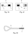
- the other object is an electronic imager making it possible to form a first image, the first image being the revealing frame or the combined image, in order to be able to superimpose it on a second image present on the secure article, the second image being the other of the revelation frame and the combined image.
- electronic imager is understood to mean an electronic device making it possible to produce an image by display or projection.
- the electronic imager may include a screen on which the first image is displayed.
- the electronic imager can include a screen of any known type, for example a computer, television, mobile phone, book or diary screen. electronic, a personal digital assistant ("Personal Digital Assistant"), a digital tablet, a watch face, this list being non-exhaustive.
- the electronic imager can be a projector, without or without a screen onto which the projection is carried out.
- the projector can make it possible to project the first image on a background or on the security article.
- the electronic imager can be a projector of any known type, for example a slide projector, a video projector, an overhead projector, a picoprojector or nanoprojector, for example a miniaturized video projector integrated into a portable device (PDA, cell phone, laptop computer, etc. for example), a cinematographic projector, this list being non-limiting.
- a projector of any known type for example a slide projector, a video projector, an overhead projector, a picoprojector or nanoprojector, for example a miniaturized video projector integrated into a portable device (PDA, cell phone, laptop computer, etc. for example), a cinematographic projector, this list being non-limiting.
- the electronic imager preferably makes it possible to generate a pixelated image, each pixel of which is individually addressable, preferably with at least 256 levels of gray or colors, and / or with a resolution of between 50 and 1000 dpi ("Dot Per Inch” or “Points Per Inch”).
- the electronic imager can be a projector projecting visible, infrared (IR) and / or ultra-violet (UV) light.
- IR visible, infrared
- UV ultra-violet
- the electronic imager may include a screen of the LCD (“Liquid Crystal Display”), LED “Light Emitting Diode”), OLED (“Organic Light Emitting Diode”), laser, plasma, electrochromic, FED (“Field Emission Display”) type. ), SED (“Surface-conduction Electron-emitter Display”), LCOS (“Liquid Crystal On Silicon”) or even a cathode ray tube.
- LCD Liquid Crystal Display
- LED Light Emitting Diode
- OLED Organic Light Emitting Diode
- laser plasma
- electrochromic FED (“Field Emission Display”) type.
- FED Field Emission Display”
- SED Surface-conduction Electron-emitter Display
- LCOS Liquid Crystal On Silicon
- the electronic imager preferably includes a liquid crystal display (LCD).
- LCD liquid crystal display
- the screen may have a resolution of between 50 and 600 dpi, better still between 100 and 300 dpi, for example equal to 160 dpi.
- the second image may appear on an area of reduced opacity of the secure article.
- a zone of reduced opacity may in particular correspond to a zone of lesser thickness, to a zone made transparent or to a zone comprising at least one layer of a material of lower opacity.
- the opacity of said zone of reduced opacity will in particular be sufficiently low to allow observation in transmission of the first image.
- the second image is visible in transmission and in reflection.
- the second image can appear on an at least partially transparent or translucent zone of the secure article.
- the second image preferably appears on an area at least partially transparent or translucent, in particular an at least partially transparent window.
- the first image produced by the electronic imager can be displayed on the electronic imager, for example on a screen of the electronic imager.
- the first image is projected by the electronic imager, for example on a background or on the secure article.
- the second image of the secure article can be superimposed on the first image projected on the background.
- the first image is projected at least partially on the second image of the secure article.
- the article and the imager may or may not come into contact when the images are superimposed.
- the first image and / or the second image may exhibit polarization properties.
- the first image is produced by the electronic imager by means of polarized light, in particular rectilinearly, circularly or elliptically polarized light.
- the electronic imager may include a screen emitting polarized light or projecting polarized light.
- the secure article may include a polarizing filter.
- the second image can be produced using a polarizing filter.
- the steps stated above will be carried out so as to form an image which is the positive or negative image of the second image.
- at least one polarizing filter for example by printing, a polyether-based aliphatic polyurethane, for example such as that sold by the company LAMBERTI under the name Esacote® PU 21 / S.
- the composition comprising cholesteric liquid crystals when during the implementation of the method according to the invention, the composition comprising cholesteric liquid crystals is situated between the polarizing substrate and the electronic imager, the cholesteric liquid crystals modify the polarized light. of the electronic imager which is not stopped by the substrate and the areas covered with cholesteric liquid crystals appear transparent when the polarizing substrate is oriented so as to be opaque.
- the cholesteric liquid crystals exhibit an optically variable effect when the polarizing substrate is oriented so as to be opaque.
- the optically variable effect of crystals Cholesteric liquids is more generally known under the name of “colorshift” effect, the color of the cholesteric liquid crystals depending on the angle of observation and the latter being observed in particular against a dark background, preferably black in color.
- the “colorshift” effect of cholesteric liquid crystals can constitute an additional security for authenticating and / or identifying the secure article.
- the second image is defined by a first polarizing material superimposed on a second polarizing material, the first material extending in particular in patterns corresponding to the second image. and the second material extending continuously.
- the first material is preferably a cholesteric liquid crystal print and the second material is preferably a linearly polarizing substrate.
- patterns corresponding to the second image is meant that said patterns form the second image in negative or positive.
- the first and second images exhibit polarization properties
- there is only one orientation of one with respect to the other allowing one to partially mask the other.
- there is only one orientation of the first image relative to the second image making it possible not to be able to observe the first image through the polarizing zones of the second image, or vice versa.
- the first and second images exhibiting polarization properties consist of polarizing zones and non-polarizing zones. When placed in front of a light source emitting polarized light, there is only one orientation in which the polarizing areas become opaque.
- the article comprises a polarizing filter
- the polarizing filter may appear opaque, in particular black in color, only in this orientation, which is preferably single, of the first image relative to the second image.
- the presence of a single orientation of the first and second images relative to each other as described above can make it possible to authenticate and / or identify the secure article according to a first level of security.
- the electronic imager for example the screen of the electronic imager, and / or the secure article may include an indicator making it possible to inform the user on how to position the first and second images with respect to one another. 'other to obtain said orientation, for example a visual cue.
- the second image is printed with a compound, in particular liquid crystals, visible only when placed in front of an electronic imager emitting polarized light, in particular a liquid crystal screen.
- the second image is transparent under unpolarized illumination, for example under natural lighting, and is visible only under polarized illumination using the electronic imager, which provides additional security for the secure article.
- the secure article may include an integrated microcircuit, for example an RFID chip or an optical chip (activated for example by the light coming from the electronic imager), capable of communicating with the electronic imager so that the latter produces, in particular displays and / or projects information providing information on how to position the first and second images with respect to one another to obtain said orientation.
- an integrated microcircuit for example an RFID chip or an optical chip (activated for example by the light coming from the electronic imager), capable of communicating with the electronic imager so that the latter produces, in particular displays and / or projects information providing information on how to position the first and second images with respect to one another to obtain said orientation.
- the secure article may include an integrated microcircuit, for example an RFID chip or an optical chip, capable of communicating with the electronic imager so that the latter produces at least one first image, the association of which with the second image makes it possible to put implementing the method according to the invention.
- the electronic imager can produce at least a first image associated with a second image of the secure article by communication between the electronic imager and the integrated microcircuit.
- the electronic imager can also produce at least a first image from a photo and / or a video of the secure article, in particular from the second image of the secure article or from an identifier present on the. item, for example a logo or serial number.
- the photo and / or video can be produced with the electronic imager, an image capture device, for example a digital camera, connected to the electronic imager by a wired link or not and / or be transferred to the imager.
- electronic for example from a data storage device or via a network, such as the Internet.
- the first image can be produced only from the photo and / or video of the secure article, or alternatively, be produced from the photo and / or video of the secure article and additional information, for example example information present on the secure article, on the photo and / or video, entered by the user, or even received from a network, for example from a secure server.
- the electronic imager may include a program making it possible to identify the secure article, and in particular the second image, and to produce, in particular to display and / or project, a first image obtained from a database providing information. on the first image to be used according to the secure article, in particular the second image.
- the electronic imager can produce several first images and / or the secure article can include several second images, at least one of the first images making it possible to observe the authentication and / or identification information when superimposed on the least one of the second images according to the method of the invention, or vice versa.
- a given electronic imager can make it possible to authenticate and / or identify secure articles of different types, notably comprising different second images.
- the second images are differentiated by their size, their color, their shape, or even by the spacing between the frame elements or nested images or the width of the latter.
- the first images can also be differentiated by their size, their color, their shape, or even by the spacing between the elements of the frame or nested images or the width of the latter, or even by the size of the pixels, the spacing between pixels or pixel color.
- Electronic imagers can, for example, be differentiated by their brand, their model, their resolution, their type, namely computer, television or telephone screen, or projector, for example.
- first images and / or second images can make it possible to authenticate and / or identify the security article independently of the differences mentioned above.
- the first image produced by the electronic imager can come from a communication network with which the electronic imager communicates, for example a telephone network, the Internet or an internal network, the image being for example downloaded, and / or be supplied with the electronic imager, for example on a data medium, for example a hard disk, a USB stick, a CD and / or a DVD.
- the security article may, where appropriate, include such a data medium.
- the data medium can be an integrated microcircuit, for example an RFID or optical chip, communicating with the electronic imager.
- the secure article can include a luminescent zone, for example fluorescent and / or phosphorescent, and the electronic imager can project the first image on the secure article under ultraviolet (UV) lighting.
- a luminescent zone for example fluorescent and / or phosphorescent
- UV ultraviolet
- the second image may be a luminescent printing, for example produced on a black opaque background of the secure article, onto which the first image is projected under UV lighting. The second image is then visible only under UV lighting.
- the second image can still be printed on a luminescent background of the secure article, so that it is visible under both UV light and normal light.
- the subject of the invention is also a method for authenticating, according to claim 14, a secure article according to the first aspect of the invention, in which the image (s) revealed by the revelation frame is observed, the image is changed. 'viewing angle and / or position of the revealing frame relative to the combined image to observe a change in the revealed image and one concludes as to the authenticity of the article at least on the basis of this observation.
- the method may include the step of aligning the first direction (s) with the respective second direction (s) when the revealing frame and the combined image are superimposed.
- the revealing screen can be at least partially superimposed on the combined image to observe the images by folding the secure article and / or by superimposing the secure article and the other object, the angle of observation and / or the position of the revelation frame with respect to the combined image is then changed to observe a change in the revealed image and one concludes as to the authenticity of the article at least on the basis of this observation.
- the photo and / or video can be produced with the electronic imager, an image capture device, for example a digital camera, connected to the object and / or be transferred to the electronic imager, for example from a device data storage or via a network, such as the Internet.
- an image capture device for example a digital camera
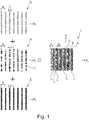
- Each nested image I i is formed of lines of nested images i i arranged periodically in the direction X I and of the same width l i constant over their entire length.
- the nested images are of the same period S.
- the lines of nested images i i are parallel longitudinal axes defining a general orientation O i of the image combined by their general direction.
- the periodicity is observed along an axis X I perpendicular to the longitudinal axis of the nested image lines.
- the lines of a nested image are continuous and of the same length, but it may be otherwise.
- the combined image I corresponds to the superposition of these nested images I 1 to I n by shifting them relative to each other along the axis X I so that the lines of nested images i 1 to i n do not overlap not between different images.
- the lines of a nested image i 1 to i 3 have the same width l 1 to l 3 equal to S / 3.
- the lines i 1 to i n of the nested images can be of widths l 1 to l n different from each other, as shown in the figure. figure 7A .
- the combined image I is formed of three nested images I 1 to I 3 .
- the first nested image I 1 is formed by a red line i 1 periodic
- the second nested image I 2 is formed by a green line i 2 periodic
- the third nested image I 3 is formed by a blue line i 3 periodic.
- the three lines of the nested images i 1 to i 3 are of the same width l .
- the lines of the nested images i 1 to i 3 are rectilinear.
- the resulting combined image I is a raster image exhibiting a periodic alternation of lines i 1 to i 3 of different colors.
- the period S is between 10 ⁇ m and 1 mm, preferably between 50 and 200 ⁇ m.
- the width l of the lines of the nested images i 1 to i n is less than or equal to 50 ⁇ m, being for example substantially equal to 33 ⁇ m. This value corresponds to a resolution of the combined image I of approximately 800 dpi, which represents a limit for conventional printers which generally have a maximum resolution of 600 dpi, and which constitutes a safety factor.
- the print definition can be sufficiently precise for the mixture of colors to appear homogeneous.
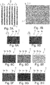
- the lines of the nested images i 1 to i n have micropatterns 7, and better still are formed by micropatterns 7.
- the micromotives 7 of the lines i i of a nested image can be colored with a single color so that the lines i i appear colored, or not.
- the micropatterns 7 are of the width l of the lines i i of the nested image and of a height of the same order of magnitude so that, in view of the resolution, the lines i i appear of a uniform color. to the eye, the micropatterns 7 not being distinguishable with the naked eye at a distance of 15 cm. The user must for example use a magnifying glass to view the micropatterns 7, which reinforces the security of the article.
- the micropatterns 7 can be in positive writing or in negative writing.
- the combined image I is formed of three nested images I 1 , I 2 and I 3 as described previously, except that the nested image lines i 1 , i 2 and i 3 are not lines of homogeneous color but lines of micropatterns 7 colored in positive writing.
- the lines i 1 are made up of a repetition of the number "100" in red color
- the lines i 2 are made up of a repetition of the word "AWS" in green color
- the lines i 3 are made up of a repetition of the word Blue “BUTTERFLY”.
- the combined image I can be formed by printing, in particular by four-color printing.
- the combined image I is formed by metallization and / or demetallization, in particular by metallization using metals of different colors for each of the nested images I 1 to I n .
- the combined image I comprises two nested images I 1 and I 2 , one being in copper and the other in aluminum.
- the nested images I 1 to I n can be glossy or matte.
- nested images are at least partially differentiated by their brightness, with nested images being matte and other nested images being glossy.
- the combined image I can also be formed by an electronic imager 100.
- the revelation frame 4 is composed of a periodic alternation of period Q constant of straight and occulting frame lines 5a, in particular of opaque and black lines, and of non-occulting lines 5b, in particular of transparent lines of parallel longitudinal axes .
- the periodicity is observed along an axis X T perpendicular to the longitudinal axis of the frame lines 5a and 5b.
- the longitudinal axes of the frame lines 5a and 5b define a general orientation of the frame O t by their general direction.
- the blackout raster lines 5a are of a constant width m less than the period Q of the raster and the transparent raster lines 5b are of a constant width k, less than the period Q.
- the width k of the lines of transparent frames 5b is greater than the width l of a nested image line.
- the widths of the blackout screen lines 5a and the transparent screen lines 5b may or may not be identical.
- the lines of frames 5a and 5b have rectilinear and parallel edges, but it may be otherwise.
- the revelation frame 4 may include other patterns such as crenellations or undulations, as illustrated respectively in figures 8A and 8B .
- the resolution of the revealing screen 4 is preferably greater than or equal to 800 dpi.
- the revelation screen 4 may as such have a homogeneous appearance to the naked eye at a normal viewing distance, taking into account its fineness.
- the revealing screen can appear to the naked eye at a distance of 15 cm as having a gray, uniform color, more or less dark depending on the width m of the blackout screen line 5a.
- a combined image and a sufficiently fine revelation screen provide anti-photocopying security
- the combined image I and / or the revealing screen 4 can be formed by printing, metallization, demetallization, laser marking, lithography or any other technique making it possible to fix or reveal an image.
- liquid crystal inks can be used, for example to print the combined image I.
- the animation in order to be revealed, may then require in addition to the revealing screen, the use of a filter.
- polarizer which may or may not be present on the article.
- the revelation screen 4 can be formed by printing or metallization and / or demetallization.
- the blackout raster lines 5a of the revealing raster 4 can be glossy or matt.
- the revelation screen 4 is different, in particular the lines of the screens are not opaque and transparent.
- the blackout raster lines can be formed of a filter that does not pass the wavelengths corresponding to the combined image and the non-blackout raster lines can at least partially pass these wavelengths.
- the period Q of the revelation frame 4 is equal to the period S of the combined image I.
- the disclosure frame 4 and the combined image I are superimposed and the general orientation O t of the disclosure frame 4 is substantially the same as the general orientation O i of the combined image I, a revealed image I r can be observed.
- the revealed image I r then corresponds to the parts of the combined image I present under the lines of transparent frames 5b for a given viewing angle.
- the blackout frame lines 5a come to mask part of the lines. of nested images i 1 to i n , the other part of the lines of nested images i 1 to i n being visible through the transparent raster lines 5b.
- the lines of transparent frames 5b all allow the visualization of the same proportion (P 1 ; ...; P n ) of the nested image lines i 1 to i n .
- the proportion P i corresponds to the proportion of a line i i of the visible nested image I i.
- the obscuring raster lines 5a make the nested image lines i 1 to i n on which they are superimposed dark and thereby prevent their visualization.
- the lines of nested images i 1 to i n superimposed on the lines of transparent frames 4b are visible to form the revealed image I r .
- the revealed images I r are observable in reflected light and in transmitted light.
- the lines of nested images i 1 to i n are all of the same width l 1 to l n and the shadowing raster lines 5a have a width m equal to 0.75 times the width of the lines of nested images i 1 to i n .
- the occulting raster lines 5a when they are well positioned relative to the nested image lines i 1 to i n , cover three quarters of one of the nested images, ie three quarters of a color; two nested images and a quarter of the third nested image are therefore visible.
- the proportion (P 1 ; P 2 ; P 3 ) of the nested image lines i 1 , i 2 and i 3 of the revealed image I r is (1; 0.25; 1) and for the figure 2C , the proportion (P 1 ; P 2 ; P 3 ) of the nested image lines i 1 , i 2 and i 3 of the revealed image I r is (1; 1; 0.25).
- the revealed image I r can appear homogeneous to the naked eye.
- a combined image I in the form of a colored frame formed of an alternation of red, green and blue lines of identical widths l and of a revealing frame of width of transparent raster line k .
- the RGB coordinates are in the form of three numbers between 0 and 255 characterizing said color, each number each representing the proportion of one of the red, green and blue components making it possible to obtain said color.
- R R max ⁇ P R
- V V max ⁇ P V
- B B max ⁇ P B
- the revealed image Ir is observable in transmitted light or in reflected light both from the side of the revealing screen 4 and from the side of the combined image I when the revealing screen 4 and the combined image I are superimposed.
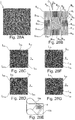
- the combined image I comprises a periodic alternation of pixels of nested images p 1 to p n in two directions X and Y.
- the pixels of nested images p 1 to p n are rectangular in shape but it could be otherwise.
- the pixels could be of another polygonal shape, in particular a square, hexagon or rhombus.
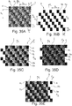
- the pixels of the figure 35A can also be seen as lines of diagonal nested images formed of pixels joined together by one of their corners periodically alternating in the Z direction.
- the pixels p 1 to p n belonging to different nested images have a different appearance, in particular a different hue, saturation, brightness, transparency, luminescence.
- the pixels p 1 to p n belonging to different nested images are of different colors, in particular red, green and blue.
- the combined image I presents in the direction X I a period Sx and in the direction Y I a period S Y.
- the directions X I and Y I are perpendicular but there could be otherwise.
- the directions X I and Y I could form between them a non-zero angle different from 90 °.
- the pixels of nested images p 1 to p n have a dimension lx and a dimension l Y according to the directions X I and Y I respectively .
- the dimensions l X and l Y are each as described above for the nested image lines i 1 to i n .
- the associated revelation frame 4 is according to the figure 35B . It presents a periodic alternation of blocking frame pixels 5a in two directions X T and Y T forming between them the same angle as the directions X I and Y I.
- the blocking frame pixels 5a are separated from each other by transparent intervals 5b and are repeated according to the periods Sx and S Y of the combined image according to the respective directions X T and Y T.
- the pixels of the revealing frame can be of a dimension mx and of a dimension m Y in the respective directions X T and Y T less than the periods S X and S Y respectively.
- the dimension mx in the direction X T is equal to the dimension l X of the pixels of nested images p 1 to p n and the dimension m Y in the direction Y T is equal to the dimension l Y of the nested image pixels p 1 to p n
- m X and my may be different from l X and l Y respectively, provided that the periods in the X and Y directions are the same.
- the revelation frame When superimposing the revelation frame 4 and the combined image I so that the directions X T and X I coincide and the directions Y T and Y I coincide, the revelation frame makes it possible to observe revealed images I r as represented on the figures 35C to 35E .
- the occulting raster pixels 5a hide one of the nested images I 1 to I n so that two of the nested images are visible.
- the revealed image I r is formed by the nested green and red images
- the revealed image I r is formed of the nested blue and red images
- the revealed image I r is formed of the nested blue and green images.
- the different revealed images I r illustrated can be obtained by moving the revealing frame 4 relative to the combined image in the direction X I , the direction Y I or the direction Z and / or by changing the viewing angle. around the directions X I and Y I or Z.
- the user can then see a change in the revealed image I r and conclude on the basis of this observation about the authenticity of the article.
- the revelation frame 4 can be formed from a plurality g of frame blocks B 1 to B g .
- Each frame block B i is as described for revelation frame 4 in relation to the figures 2A to 2C and makes it possible to reveal, when the revelation frame is superimposed on the combined image I as described above and its orientation is the same, a revealed image I r1 to I rg .
- Blocks B 1 to B g of revelation frame 4 are superimposed on the same combined image I.
- the blocks B 1 to B g of the same frame have the same period Q and the same general orientation O b .
- the general orientations O b of the blocks 10 define a general orientation of the frame Ot.
- the blocks B 1 to B g have a maximum dimension v of between 1.4 and 42 mm and an area between 0.2 and 90% of the area of the revelation screen.
- the blocks B 1 to B g have screen lines 5a of the same width m and at least two of the blocks B i and B j are out of phase with each other, that is to say have a non-zero phase shift distance dij less than the period Q, the phase shift distance dij being defined as the remainder of the division of the distance c ij between the longitudinal axis of a frame line i i of the block B i and the longitudinal axis of the line of consecutive frame i j of block B j by period Q.
- d ij rest vs ij Q
- the transparent frame lines 5b of the block B i do not reveal the same proportion of the nested images (P 1 ; ...; P n ) than that of block B j and therefore the images revealed I ri and I rj respectively by blocks B i and B j have different aspects because they do not have the same proportion (P 1 ; ...; P n ) nested images.
- the revealed images I r1 to I rg of the blocks out of phase with one another are of different colors.
- the revelation frame 4 is continuous and each of the blocks B 1 to B g has part of its outline in common with another of the blocks B 1 to B g .
- the revealed images I r1 to I rg can form a pattern, in particular a text, an alphanumeric sign, an ideogram, a geometric shape, an object, a person and / or an animal, for example reproducing a pattern present elsewhere on the article secured.
- the images revealed I r1 to I rg by the different blocks B 1 to B g can vary. This change in appearance can give the impression of movement or cause the color of a pattern to vary.
- the figures 3A to 3F and 5A to 6C illustrate examples of revelation frames 4 formed of blocks B 1 to B g superimposed on a combined image.
- the revelation frame 4 is superimposed on a combined image I formed of three nested images colored respectively in red, green and blue, as described previously.
- the revelation frame 4 comprises six rectangular blocks B 1 to B 6 each forming approximately 1/6 th of a rectangle, as can be seen on the figure 3B .
- Each of the blocks B 1 to B 6 has an outline common with at least two other blocks B 1 to B 6 .
- the area of each block B 1 to B 6 is substantially between 20% and 15% of the area of the revelation screen 4.
- Blocks B 1 , B 2 and B 3 are out of phase with each other and block B 4 is not out of phase with block B 1 , block B 5 is not out of phase with block B 2 and block B 6 is not out of phase with respect to block B 3 so that each of blocks B 1 to B 6 is out of phase with respect to blocks B 1 to B 6 which are adjacent to it.
- the blocks B 1 and B 3 are arranged one above the 'other and have an edge 6 13 , shown by dotted lines, in common while the blocks B 1 and B 2 are arranged next to each other with an edge 6 12 in common.
- the blackout raster lines of block B 1 have a corner 9 in common with the blackout raster lines of block B 3 . It is the same with blocks B 3 and B 5 , B 2 and B 4 , and B 4 and B 6 .
- block B 1 is phase-shifted from block B 3 by a phase-shift distance d 13 equal to the width m of a blackout frame line. It is the same with blocks B 3 and B 5 , B 2 and B 4 , and B 4 and B 6 .
- the distance c 12 between the last blackout frame line of block B 1 and the consecutive blackout frame line of block B 2 is equal to five times the width m of a blackout frame line.
- the block B 1 is phase-shifted from the block B 2 by a phase-shift distance d 12 equal to twice the width m of a blackout frame line. It is the same with blocks B 3 and B 4 , and B 5 and B 6 .
- the width m of the blackout raster line 5a is equal to the width l of a nested image line so that the transparent raster line can reveal two nested images.
- the revealed images I r1 , I r2 and I r3 are out of phase and the respective revealed images I r1 and I r4 , Ir 2 and I r5 , and Ir 3 and I r6 are identical.
- the revealed images I r1 to Ir 6 form a rectangle composed of 6 squares each formed by a revealed image I r1 to I r6 , each square being adjacent to squares of different colors.
- the nested image I r1 has proportions of nested images (1; 1; 0), which corresponds to an RGB color (170, 170, 0)
- the nested image I r2 has proportions (1 ; 0; 1), which corresponds to an RGB color (170,0, 170)
- the nested image I r3 has proportions (0; 1; 1), which corresponds to an RGB color (0, 170 , 170).
- the figures 3C to 3E represent images revealed I r1 to I r6 under different observation conditions.
- the blocks B 1 to B g are distinct zones of the revelation frame 4 which do not overlap. It may be otherwise, in particular due to manufacturing tolerances.
- the blocks B 1 to B g can be in zones of the revealing screen 4 which overlap on less than 5% of the area of the revealing screen.
- the blackout frame lines of block B 1 have a region 11 in common with the blackout frame lines of block B 3 .
- the blackout frame lines of block B 1 are separate from the blackout frame lines of block B 3 .
- the distance c 12 between the last blackout frame line of block B 1 and the consecutive blackout frame line of block B 2 is equal to twice the width m of a blackout frame line.
- the revelation frame 4 comprises sixteen blocks B 1 to B 16 each forming a disk sector.
- Each block B 1 to B 16 is adjacent to two blocks and all the blocks B 1 to B 16 meet at the center of the disc.
- the blocks B 1 , B 2 B 3 and B 4 are out of phase with each other and the blocks B 5 , B 9 and B 13 are not out of phase with the block B 1 , the blocks B 6 , B 10 and B 14 are not not out of phase with block B 2 , blocks B 7 , B 11 and B 15 are not out of phase with block B 3 and blocks B 8 , B 12 and B 16 are not out of phase with block B 4 so that each of the blocks B 1 to B 16 is out of phase with respect to the three blocks B 1 to B 16 which succeed it and which precede it when one turns in the direction of clockwise.
- the shading raster lines 5a have a width m substantially equal to three quarters of the width l of the nested image lines.
- Block B 1 is phase-shifted from block B 2 by a distance d 12 equal to three quarters of the width l of a nested image line i 1 to i 4 , block B 1 is phase-shifted from block B 3 d ' a distance d 13 equal to three half of the width l of a nested image line i 1 to i 4 and the block B 1 is phase-shifted from block B 4 by a distance d 14 equal to nine quarters of the width l of a nested image line i 1 to i 4 .
- the revealed images I r1 to I r16 form a disc composed of 16 sectors each formed by a revealed image I r1 to I r16 , each sector being situated between sectors of different colors.
- the nested image I r1 presents proportions of nested images (1; 0.25; 1), that is to say an RGB color of approximately (191, 48, 191)
- the nested image I r2 presents proportions (0.5; 0.75; 1), i.e. an RGB color of approximately (95, 143, 191)
- the nested image I r3 has proportions (0.5; 1; 0.75), i.e. a RGB color of about (95, 191, 143)
- the nested image I r4 has proportions (1; 1; 0.25), or an RGB color of about (191, 191,48).
- the figures 5B to 5D represent images revealed I r1 to I r16 under different observation conditions.
- the revelation frame 4 comprises four blocks B 1 to B 4 of different shapes.
- the block B 2 represents the number 1
- the blocks B 3 and B 4 represent the number 0
- the block B 1 is a rectangular block in which the other blocks are inserted. All the blocks B 1 to B 4 are out of phase with one another.
- the images are schematic for illustrative purposes however when observing the revelation frame alone shown in the figure 6A , the pattern "100" is not distinguishable at a normal viewing distance, between 30 cm and 10 cm and preferably 15 cm.
- the occulting raster lines 5a have a width m substantially equal to three quarters of the width l of the nested image lines, as in the example of figures 5A to 5D .
- the revealed images I r1 to I r4 form the number 100 on a colored background, the colors of all the numbers being different.
- the figures 6B to 6C represent images revealed I r1 to I r4 under different observation conditions.
- At least two blocks B i and B j have blackout frame lines of respective widths m i and m j that are different.
- the lines of transparent frames 5b of the block B i do not reveal the same proportion of the lines of nested images (P 1 ; ...; P n ) than that of block B j and therefore the images revealed I ri and I rj respectively by blocks B i and B j do not have the same proportion (P 1 ; ...; P n ) nested images.
- the revealed images I r1 to I rg of the blocks of widths m 1 to m g are of different colors.
- Each sub-block 15 allows the observation of an image revealed I r by superposition on the combined image.
- the revealed image is of the same shape as for a block having an occulting raster line of the same width and in the case of image (ii), the revealed image obtained depends on the position and the width of the weft lines 15a and 15b.
- the combined image I illustrated on figure 11A comprises blocks C 1 to C 3 and the revelation frame 4 is in the form of a single block.
- the blocks of the combined image are each as described in relation to the figure 1 .
- the combined image blocks C1 to C3 are in rectangular form.
- the blocks C 1 and C 2 are out of phase with one another by a width l of a nested image line and the blocks C 1 and C 3 are not out of phase with one another.
- the revealing screen has lines of opaque screens 5a having a width m equal to the width l of a line i 1 to i 3 of nested images.
- the revealed images I r1 and I r3 are composed of all the red and blue lines and therefore present a proportion (1; 0; 1) of the nested images and the revealed image I r2 is composed of all the red lines and green and has a proportion (1; 1; 0) of the nested images.
- the revealed images I r1 to I r3 change, for example going from the figure 11B of figures 11C and 11D .
- a secure article 10 comprises a non-opaque substrate 20, for example perfectly transparent, having a first face 20a carrying the combined image I.
- the second face 20b of the substrate 2, opposite to the first, carries the weft of revelation 4.
- the revelation frame 4 makes it possible to observe one or more revealed images I r .
- the user changes the observation conditions and the revealed image (s) I r are modified as described above.
- the thickness e of the substrate is preferably greater than or equal to approximately the period Q.
- a substrate whose thickness e is less than or equal to 30 ⁇ m, better still 25 ⁇ m, for example between 20 and 30 ⁇ m, or even 20 and 25 ⁇ m, limits included or excluded.
- Another possibility for varying the direction of observation of the secure article may be to deform the substrate, for example around a folding axis, as illustrated in figure 13 .
- the combined image I can be obtained by micro-photolithography of the thread and the revelation screen 4 can be produced by means of offset printing with inks crosslinking under UV carried out in a second step, when printing the article.
- the revelation screen 4 can be associated, where appropriate, with a print pattern of the article.
- the pattern of the revelation screen 4 can be printed elsewhere than in superposition with the combined image I, on the article, at the same scale or at a different scale.
- the printing of the revelation screen 4 may extend beyond the combined image I and extend over the secure article 10, as illustrated in figure 14 .
- the secure article 10 may include at least two windows 31 and 32 allowing each of the faces of the wire to be observed respectively, in reflection.
- the article may include, at the level of the windows 31 and 32, gaps in material and transparent zones 35 and 36 allowing the observation of the images revealed on both sides of the secure article 10.
- the nested images are observable through the reveal screen 4 on the side of the window 31 and with the reveal screen as a background, on the side of the window 32.
- the article 10 may also include a through window 31, as shown in figure 16D , the revelation frame 4 and the combined image I being located at least partially in this through window. In this way, it is possible to observe the images revealed on both the front side and the back side of the secure article 10.
- the disclosure frame 4 and the combined image in the form of a security thread can still be incorporated into a secure article 10 which have alternating windows 31 and 32 on the front side and on the back side, as illustrated in figure figure 16C . It is thus possible to observe the images revealed both on the front side and on the back side of the secure article 10 at the level of the windows 31 and 32, and in particular due to the presence of the shortages of material and of the transparent zones 35. and 36.
- FIG. 17 We have represented on the figure 17 an example of a secure article 10 comprising a perforation 40 in which are placed at least partially two sub-elements, in particular in the form of foils or patches, 41 and 42.
- the sub-element 41 comprises for example a revelation frame 4 and the sub-element 42 comprises for example the corresponding combined image I.
- the sub-elements 41 and 42 can be superimposed at least partially on the edges of the perforation 40 with or without a thickness compensation.
- the sub-elements 41 and 42 can be at least partially transparent or translucent.
- the observation of the revealed images can be done by observation in reflection or in transmission, for example using a light source located behind the article 10 during the observation.
- the secure article 10 comprises a combined image I produced in the form of impressions.
- the prints are for example made on the surface of the secure article 10.
- a sub-element 43 in particular in the form of a foil or patch, is placed on the prints constituting the combined image I, the sub-element 43 comprising the corresponding revealing screen 4, for example produced on the surface of the sub-element 43.
- the secure article 10 may or may not be opaque.
- the secure article 10 can be at least partially transparent or translucent to allow observation of the nested images, in particular on the side of the combined image I.
- the combined image comprises two metallizations of different colors each corresponding to a nested image, in particular a nested copper image and a nested aluminum image.
- the combined image comprises at least two metallizations, in particular of the same color, of different optical densities each corresponding to a nested image, thus creating a brightness contrast.
- the nested aluminum image can be of high optical density, which makes it look shiny.
- the revelation screen 4 may have a matt appearance.
- the superposition of the combined image I and of the revelation screen 4 makes it possible to obtain, according to the blocks B 1 to B g , dull or shiny revealed images I r1 to I rg.
- a displacement of the revealing frame 4 relative to the combined image I along the X axis can make it possible to reverse the appearance of the revealed images I r1 to I rg at the level of the different blocks B 1 to B g , c ' that is to say that the revealed images I r1 to I rg which were bright can become dull and vice versa.
- the secure article 10 comprises a window 50, preferably at least partially transparent, in which appears the revelation frame 4.
- the article 10 also comprises a combined image I carried on the article 10, for example by printing, in particular intaglio printing, offset printing or metallization and / or demetallization.
- the zone in which the combined image 2 appears can also be at least partially transparent.
- the user To observe the revealed image, the user must therefore fold the secure article 10, as illustrated in figure 20 , to bring the revelation frame 4 back to the combined image I so that their general orientation is the same and observe the image (s) revealed I r .
- the revealed images are not visible when the article 10 is not folded and it takes user action, namely folding the secure article 10, to make them appear.
- the secure article 10 comprises a window 50, preferably at least partially transparent, in which appears the combined image I.
- the article 10 also comprises a patch 55 comprising for example holographic prints, on which the revelation screen appears. 3.
- the patch 55 can also be at least partially transparent.
- the patch 55 may include metallizations and / or demetallizations, for example made of aluminum, and the revelation screen 4 may include holographic impressions and / or metallizations and / or demetallizations.
- article 10 comprises a window 50, preferably at least partially transparent, in which appears the revelation screen 4.
- Article 10 also comprises a security thread 60 on which appears the combined image I.
- the security thread 60 can also be at least partially transparent or include a partially transparent zone at the level of the combined image I.
- article 10 comprises a security thread 60 of sufficient width to alternately display combined images I and revelation screens 4.
- the security thread 60 is at least partially transparent or has one or more zones. at least partially transparent at the level of the combined images I and / or of the revealing frames 4.
- article 10 comprises a security thread 60 on which appears a revelation screen 4.
- Article 10 also comprises a combined image I, for example in the form of an offset printing on article 10.
- the security thread 60 can be at least partially transparent or have an at least partially transparent zone.
- the article 10 can also include an area at least partially transparent at the level of the combined image I.
- article 10 has two security threads 60a and 60b.
- the security thread 60a comprises three combined images I and the security thread 60b comprises three revelation frames 4.
- the security thread 60a and / or the security thread 60b can be at least partially transparent or comprise at least one at least partially transparent zone, in particular at the level of a combined image I or of a revelation screen 4.
- article 10 comprises a foil 70 on which appears an alternation of combined images I and revelation frames 4.
- the foil 70 can be at least partially transparent or comprise at least one zone at least partially transparent at the level of a combined image I and / or of a revelation frame 4.
- article 10 comprises a security thread 60 on which appears a combined image I.
- Article 10 also comprises a patch 55, which may or may not include holographic metallizations, on which appears a revelation screen 4.
- the security thread 60 can be at least partially transparent or include an at least partially transparent zone at the level of the combined image I.
- the patch 55 can also be at least partially transparent, in particular at the level of the revelation screen 4.
- the combined images I and the revealing frames 4 can be inverted.
- the at least partially transparent zones can be situated at the level of the combined images I or of the revealing means 4, or at the level of both at the same time.
- the security thread (s) 60, 60a and 60b can be introduced into the secure article 10 in a conventional manner, for example on the surface, in bulk or in window (s).
- Authentication of the articles 10 can be accomplished by folding them 10 lengthwise or crosswise so as to at least partially overlap the combined images I and disclosure screens 4, and then moving relatively relative to each other. others so as to visualize, for example, the illusion of movement and / or by modifying the angle of observation of the combined images I and of the superimposed revelation screens 4.
- the article or the assembly can comprise two revelation frames 4a and 4b as described above being superimposed on the same combined image I.
- the two revelation frames are preferably of different general orientations O ta and O tb forming between them a non-zero angle ⁇ , preferably between 0 ° and 180 °, limits excluded, better still between 10 and 30 °, for example here substantially equal to 20 °.
- the user To observe the images revealed by one or the other of the frames, the user must therefore superimpose the combined image I and the revealing frames 4a and 4b by folding article 10 or superimposing article 10 and of another object and rotate the combined image I with respect to the revealing frames 4a and 4b.
- the user can also move them relative to each other along an axis perpendicular X to the general orientation of the combined image to observe a change in the image (s) revealed in one of the frames.
- the two revelation frames 4a and 4b may or may not be separated from each other.
- the disclosure frame 4b is an inclusion in the disclosure frame 4a.
- the first revealing frame 4a is square in shape and is formed of 17 blocks B 1a to B 17a , in particular a central block B 1a of substantially square shape flanked by 16 side blocks B 2a to B 17a also of square shape.
- 12 side blocks B 2a to B 13a are juxtaposed all around the central block B 1a to form a square of width equal to twice the width of the central block B 1a and 4 side blocks B 14a to B 17a ) are each superimposed completely in two 12 side blocks B 2a to B 13a respectively to blocks B 3a and B 4a , B 6a and B 7a , B 9a and B 10a , and B 12a and B 13a .
- the blocks B 1a to B 17a are all substantially square in shape.
- the side blocks B 2a to B 17a are of width substantially equal to half the width of the central block B 1a .
- the superposition of the side blocks B 14a to B 17a on the other side blocks B 2a to B 13a allows the formation of 8 sub-blocks as described above.
- Each lateral block B 2a to B 13a is out of phase with respect to the lateral block B 2a to B 13a which precedes it and which succeeds it.
- the side blocks B 2a , B 5a , B 8a and B 11a forming the corners of the revealing screen 4 are not out of phase with each other and are not out of phase with respect to the central block B 1a .
- the second revelation frame 4b is rectangular in shape and it is formed of 4 blocks B 1b to B 4b of different shapes.
- Block B 2b represents number 1
- blocks B 3b and B 4b represent number 0
- block B 1b is a rectangular block in which the other blocks are inserted.
- the blocks B 2b to B 4b are not out of phase with one another but are out of phase with respect to the block B 1b .
- the two revelation frames 4a and 4b have respective general orientations O ta and O tb which are different and form between them an angle ⁇ substantially equal to 20 °.
- the occulting raster lines 5a have a width m substantially equal to three quarters of the width l of the nested image lines, as in the example of figures 5A to 5D .
- the revelation screens 4a and 4b are superimposed on the same combined image I, illustrated on the figure 28A .
- blocks B 1a to B 17a reveal revealed images I r1a to I r21a forming a central square I r1a surrounded by squares smaller I r2a to I r21a of different colors.
- the color of the small squares I r2a , I r5a , I r8a and I r11a in the corners is the same as that of the central square I r1a .
- the second revelation frame 4b does not form any visible image due to a Moiré phenomenon between the lines of the second revelation frame 4b and the lines of the combined image I.
- the figures 28C and 28D represent images revealed under different observation conditions but always with the same orientation of the revelation frames 4a and 4b and of the combined image. The color of the revealed images changes.
- the revealed images I r1b to I r4b form the number 100 on a colored background, the colors of all the numbers being identical.
- the first revelation frame 4a does not form a visible image due to a Moiré phenomenon between the lines of the first revelation frame 4a and those of the combined image I.
- the figures 28E and 28F represent images revealed under different observation conditions always with the same orientation of the revelation frames 4a and 4b and of the combined image. The color of the revealed images changes.
- the superposition of the revelation frame 4 and of the combined image I can be done by folding the secure article 10 and the change of orientation can be done by rotating the part of the secure article 10a carrying the combined image I with respect to the part of the secure article 10b bearing the revelation frame 4.
- the electronic imager 100 is for example a computer screen on which is displayed a first image 110, the first image 110 being the revealing frame 4 or the combined image I.
- the secure article 10 is for example in the form of a banknote and comprises a second image 120, the second image being the revealing frame 4 if the first image is the combined image and vice versa.
- the secure article 10 is placed on the screen of the electronic imager 100 so as to at least partially superimpose the first image 110 on the second image 120 in order to observe the revealed image (s) I r and to deduce therefrom authentication information. and / or identification of the secure article 10.
- the secure article 10 can be moved relative to the screen of the electronic imager 100 or the observer can change the viewing angle to allow observation of a change in the revealed image (s) I r .
- the secure article 10 remains stationary relative to the screen of the electronic imager 100 and the first image 110 is animated by a movement on the screen, for example a translation, for example using 'a program activated or not by the user.
- the electronic imager 100 is for example in the form of a digital projector, projecting a first image 110 on a background 150, for example the wall of a room.
- the secure article 10 comprising the second image 120 can then be superimposed at least partially on the first image 110 projected onto the background 150 to allow the observation of the revealed image (s) I r .
- the electronic imager 100 is a projector which projects the first image 110 directly onto the secure article 10.
- the first image 110 can, as in the example of the figure 31 , be projected, for example in the form of a “W”, onto an area of the secure article 10 where the second image 120 is not present. Then, the secure article 10 is for example folded on itself so in superimposing the second image 120, for example in the form of an “A”, on the first image 110 projected by the electronic imager 100.
- the part of the secure article 10 comprising the second image 120 can in particular be folded over the part comprising the first image 110, this part remaining stationary, so that the first image 110 is situated between the imager 100 and the second image 120.
- the first image 110 is projected directly onto the second image 120 of the article 10.
- the projection of the first image 110 onto the second image 120 of the article 10 can allow superimposition on the surface. less partial of the first and second images.
- the imager electronics 100 can be moved relative to item 10 to move revealing frame 4 relative to combined image I.
- the electronic imager 100 is a screen displaying several first images 110a, 110b, 110c and 110d.
- the first images 110a to 110d can have different properties, for example different shapes, colors, dimensions, frame elements.
- the first images 110a to 110d are differentiated so as to allow at least one of them to be associated with at least one second image 120 present on an article 10.
- the article 10 comprises several second different images 120, as can be seen for example on the figure 15 , and the electronic imager 100 produces one or more first images 110.
- the electronic imager 100 produces one or more first images 110.
- the electronic imager 100 can display one or more indicators 140a, 140b, 140c and 140d making it possible to inform the user on how to position the article 10 shown on the diagram. figure 33 relative to the imager.
- the indicators 140a to 140d can make it possible to know where to position the upper right corner of the article 10, so as to correctly superimpose a second image 120 of an article 10 on a first displayed image 110a, 110b, 110c or 110d. on the screen of the electronic imager 100.
- the article 10 can comprise an integrated microcircuit 152, for example an RFID or optical chip, making it possible to communicate with the electronic imager 100 in order to control the display of an indicator as described above or to broadcast information on the manner to position the first and second images.
- an integrated microcircuit 152 for example an RFID or optical chip
- the chip 152 is able to communicate with the electronic imager 100 to make it possible to produce the first image 110 associated with the second image 120.
- the second image 120 is illuminated with the electronic imager 100.
- the chip 152 comprises information transmitted to the electronic imager 100 which projects or then displays the first image 110 based on this information.
- the article 10, in particular the second image 120, can be photographed and / or filmed by a digital camera belonging to or linked to the electronic imager 100.
- a recognition program can then make it possible to recognize the second image 120 and to acquire from there.
- a database a first image 110 associated with the second image 120.
- the database is for example stored on a secure server.
- the first image 110 thus obtained is displayed and / or projected by the electronic imager 110 to make it possible to authenticate and / or identify the article 10.
- the electronic imager 100 is in the form of a portable telephone on which is displayed a first image 110 in the form of a combined image I.
- the article 10 comprises a polarizing filter on which the second image 120 has been formed under form of revealing frame 4.
- the article 10 comprising the second image 120 in the form of revealing frame 4 is superimposed on the first image 110 in the form of combined image I produced by the electronic imager 100, the latter emitting a polarized light.
- the article 10 comprising the revealing screen 4 can be moved by a translational movement along the X axis relative to the combined image I displayed by the screen of the electronic imager 100, so as to change the or the images revealed I r .
- Such a method makes it possible to authenticate and / or identify the security article 1 according to several security levels.
- the electronic imager 100 is a screen, in particular of the LCD type, comprising a plurality of pixels preferably forming a combined image, for example as described in figure 35A .
- the invention is not limited to the examples illustrated.
- the secure article can be made with other first, second or third level securities, for example.
Description
La présente invention se rapporte au domaine des articles sécurisés.The present invention relates to the field of secure articles.
Afin de se prémunir de contrefaçons ou de falsifications et afin d'augmenter le niveau de sécurisation, il est connu d'utiliser des éléments de sécurité appliqués en surface ou introduits en masse ou en fenêtre(s) dans un article sécurisé, par exemple une étiquette, un emballage, notamment pour des médicaments, des aliments, des cosmétiques, des pièces électroniques ou des pièces détachées.In order to guard against counterfeiting or falsification and in order to increase the level of security, it is known to use security elements applied on the surface or introduced en masse or in window (s) in a secure article, for example a label, packaging, especially for drugs, food, cosmetics, electronic parts or spare parts.
L'article sécurisé peut notamment être choisi parmi un moyen de paiement, tel qu'un billet de banque, une carte bancaire, un chèque ou un ticket restaurant, un document d'identité tel qu'une carte d'identité, un visa, un passeport ou un permis de conduire, une carte sécurisée, un ticket de loterie, un titre de transport ou encore un ticket d'entrée à des manifestations.The secure article can in particular be chosen from a means of payment, such as a bank note, a bank card, a check or a restaurant ticket, an identity document such as an identity card, a visa, a passport or driving license, a secure card, a lottery ticket, a transport ticket or an entrance ticket to events.
Il est connu des demandes de brevet
Cependant, ces brevets se limitent en général à la visualisation d'une seule image imbriquée à la fois.However, these patents are generally limited to viewing a single nested image at a time.
Il est également connu de la demande de brevet
Il existe un besoin pour bénéficier d'articles sécurisés comportant un système optique anti-contrefaçon utilisant les outils des acteurs du domaine des articles sécurisés, capable de produire des effets optiques pouvant contribuer à l'authentification et/ou l'identification de l'article, et dont l'incorporation éventuelle dans un article tel qu'un papier puisse se faire relativement aisément.There is a need to benefit from secure articles comprising an anti-counterfeiting optical system using the tools of players in the field of secure articles, capable of producing optical effects which can contribute to the authentication and / or identification of the article. , and whose possible incorporation into an article such as a paper can be done relatively easily.
L'invention vise à répondre à ce besoin et a pour objet, selon un premier de ses aspects, un article sécurisé comportant une trame de révélation et une image combinée, ou un ensemble comportant un article sécurisé et un autre objet, selon la revendication 1.The invention aims to meet this need and has for object, according to a first of its aspects, a secure article comprising a revelation frame and a combined image, or an assembly comprising a secure article and another object, according to
Le fait d'obtenir une image révélée formée de plus d'une image imbriquée permet d'avoir de nouveaux effets visuels selon les images imbriquées visibles, et ainsi offre de nouvelles possibilités d'authentification, notamment accessibles à l'homme de la rue.The fact of obtaining a revealed image formed of more than one nested image makes it possible to have new visual effects according to the visible nested images, and thus offers new possibilities of authentication, in particular accessible to the man in the street.
Grâce à l'invention, il est ainsi possible de bénéficier d'un article sécurisé offrant un nouveau moyen d'authentification, consistant en la formation d'images révélées différentes, conduisant par exemple à la formation d'un motif coloré particulier facilement reconnaissable par l'homme de la rue.Thanks to the invention, it is thus possible to benefit from a secure article offering a new means of authentication, consisting in the formation of different revealed images, leading for example to the formation of a particular colored pattern easily recognizable by the man in the street.
L'autre objet précité est par exemple semblable dans sa fonction et/ou dans sa forme à l'article sécurisé selon l'invention. Par exemple, l'article sécurisé et l'autre objet sont des billets de banque, notamment avec la même valeur fiduciaire. L'article sécurisé et l'autre objet peuvent alors ne se différencier l'un de l'autre que par un numéro de série par exemple.The other aforementioned object is for example similar in its function and / or in its form to the secure article according to the invention. For example, the secure article and the other object are banknotes, in particular with the same fiduciary value. The secure article and the other object can then only be differentiated from one another by a serial number for example.
La trame de révélation comporte des éléments de trame occultants et des éléments de trame non-occultants.The revealing screen has blackout screen elements and non-blackout screen elements.
Les éléments occultants apportent un contraste visuel avec les éléments non-occultants. La frontière entre un élément occultant et un élément non-occultant est ainsi déterminée par le fait de pouvoir ou non observer l'effet recherché, par superposition avec l'image combinée.The blackout elements provide a visual contrast with the non-blackout elements. The border between a blackout element and a non-blackout element is thus determined by whether or not it is possible to observe the desired effect, by superposition with the combined image.
Cette observation peut se faire à travers les éléments non-occultants. En variante, l'image combinée est située entre la trame de révélation et l'observateur, et les éléments occultants empêchent l'observateur de discerner les éléments occultants de l'image imbriquée qui lui sont superposés. Dans des exemples, l'élément non-occultant est parfaitement transparent ou d'une opacité uniforme suffisamment faible ou encore d'une teinte suffisamment claire pour permettre d'observer à travers lui ou sur lui le ou les éléments d'images imbriquées conduisant à l'effet recherché. Dans ce cas, la dimension selon une direction de l'élément non-occultant correspond à la largeur selon cette direction de la zone parfaitement transparente ou d'opacité uniforme suffisamment faible ou de teinte suffisamment claire. Dans ces exemples, la transition entre un élément occultant et un élément non-occultant est franche. Dans d'autres exemples, l'élément occultant et/ou l'élément non-occultant forme(nt) un dégradé. Dans ce cas la limite de l'élément non-occultant selon une direction, utile pour déterminer sa dimension selon cette direction, est celle à partir de laquelle l'opacité est suffisamment forte ou la teinte suffisamment sombre pour empêcher de voir l'effet recherché à travers ou sur l'élément. Par exemple, dans le cas où la transition entre un élément occultant et un élément non-occultant se fait avec un dégradé continu de gris d'opacité variant selon une direction entre Opmin et Opmax, et qu'au-delà d'une opacité Opocc il n'est plus possible de voir l'effet recherché à travers l'élément, la dimension de l'élément non-occultant est donnée par la dimension selon cette direction de la zone de l'élément où l'opacité est inférieure ou égale à Opocc.This observation can be done through the non-occulting elements. As a variant, the combined image is located between the revealing frame and the viewer, and the shadowing elements prevent the viewer from discerning the shadowing elements of the nested image which are superimposed on it. In examples, the non-occulting element is perfectly transparent or of a sufficiently low uniform opacity or else of a sufficiently light shade to make it possible to observe through it or on it the element or elements of nested images leading to the desired effect. In this case, the dimension along one direction of the non-occulting element corresponds to the width along this direction of the perfectly transparent zone or of sufficiently low uniform opacity or of sufficiently light shade. In these examples, the transition between a blackout element and a non-blackout element is straightforward. In other examples, the blackout element and / or the non-blackout element form (s) a gradient. In this case the limit of the non-blackout element in one direction, useful for determining its dimension in this direction, is that from which the opacity is sufficiently strong or the shade sufficiently dark to prevent seeing the desired effect. through or on the element. For example, in the case where the transition between a blackout element and a non-blackout element is done with a continuous gradient of opacity gray varying in one direction between Op min and Op max , and beyond a opacity Op occ it is no longer possible to see the desired effect through the element, the dimension of the non-occulting element is given by the dimension according to this direction of the zone of the element where the opacity is less than or equal to Op occ .
De préférence, la trame de révélation comporte un nombre fini d'éléments de trame. De préférence encore, les éléments de trame ne présentent aucun dégradé.Preferably, the revealing frame comprises a finite number of frame elements. More preferably, the raster elements do not exhibit any gradient.
De préférence encore, les éléments non-occultants sont chacun d'opacité ou de luminosité (L* dans le système (L*, a*, b*) CIE94) uniforme, qui peut être nulle, respectivement faible, et les éléments occultants sont également de préférence d'opacité ou de luminosité uniforme.More preferably, the non-blackout elements are each opacity or luminosity (L * in the (L *, a *, b *) CIE94 system) uniform, which can be zero, respectively weak, and the blackout elements are also preferably opacity or uniform brightness.
L'image combinée peut comporter une alternance périodique d'éléments d'images imbriquées selon plusieurs premières directions, en particulier deux premières directions perpendiculaires entre elles, comme détaillé plus loin.The combined image can comprise a periodic alternation of elements of nested images in several first directions, in particular two first directions perpendicular to each other, as detailed below.
L'image combinée peut comprendre au moins deux images imbriquées, de préférence au moins trois.The combined image can include at least two nested images, preferably at least three.
L'image combinée peut comporter au moins deux éléments de chaque image imbriquée, de préférence au moins trois.The combined image can include at least two elements of each nested image, preferably at least three.
Selon la ou chacune des directions, les éléments successifs d'une même image imbriquée peuvent être espacés entre eux d'une distance définissant une période.Depending on the or each of the directions, the successive elements of the same nested image can be spaced apart by a distance defining a period.
La ou chaque période peut être comprise entre 10 µm et 1 mm, de préférence entre 50 µm et 200 µm.The or each period may be between 10 μm and 1 mm, preferably between 50 μm and 200 μm.
Selon l'invention, les éléments d'images imbriquées appartenant à des images imbriquées différentes sont de couleurs différentes. On a selon l'invention un écart colorimétrique ΔE*94 selon la C.I.E. 1994 supérieur ou égal à 2, de préférence supérieur ou égal à 3. Ceci permet d'avoir une image combinée polychrome.According to the invention, the nested image elements belonging to different nested images are of different colors. According to the invention, there is a colorimetric difference ΔE * 94 according to the C.I.E. 1994 greater than or equal to 2, preferably greater than or equal to 3. This makes it possible to have a polychrome combined image.
Comme cela est communément admis et précisé dans la C.I.E. 1994, la couleur est définie par la combinaison de trois paramètres que sont la teinte, la saturation et la luminosité. La teinte correspond à la perception de la couleur mesurée sur un disque chromatique, la saturation correspond à la pureté de la couleur et la luminosité correspond au degré d'éclaircissement ou d'assombrissement d'une couleur.As is commonly accepted and specified in the C.I.E. 1994, the color is defined by the combination of three parameters which are the hue, the saturation and the luminosity. Hue is the perception of color measured on a color disk, saturation is the purity of the color, and lightness is the degree of lightening or darkening of a color.
De préférence, les éléments d'images imbriquées appartenant à des images imbriquées différentes sont de teintes différentes.Preferably, the nested image elements belonging to different nested images are of different hues.
Les éléments appartenant à des images imbriquées différentes, notamment à au moins deux des images imbriquées différentes, peuvent être différents par leurs aspects, notamment leurs teintes, opacités, saturations, luminescences ou brillances, et/ou présenter un contraste, notamment un contraste de saturation, d'intensité, de teinte et/ou de luminance, et/ou un écart colorimétrique suffisant pour permettre de distinguer, notamment sous lumière blanche, deux éléments d'images imbriquées adjacents lorsqu'ils sont observés avec un certain grossissement. Ainsi, au moins deux des, mieux toutes les images imbriquées, sont d'aspects différents.The elements belonging to different nested images, in particular to at least two of the different nested images, can be different in their appearances, in particular their hues, opacities, saturations, luminescences or shine, and / or present a contrast, in particular a saturation contrast , intensity, hue and / or luminance, and / or a sufficient colorimetric difference to make it possible to distinguish, in particular under white light, two adjacent nested image elements when viewed at some magnification. So at least two of the, better all nested images, look different.
Les éléments d'image imbriquée d'une même image imbriquée sont, selon l'invention, de la même couleur mais d'une couleur différente de celles des autres images imbriquées. Lors de la superposition de la trame de révélation avec l'image combinée, à des conditions d'observation données, l'image révélée peut être alors une image dont la couleur est définie par la proportion de chaque image imbriquée visible, c'est-à-dire la proportion de chaque couleur. Pour chaque image révélée, la proportion d'une image imbriquée est comprise entre 0 et 1, la valeur 0 étant attribuée à une image imbriquée lorsque cette dernière n'est pas une composante de l'image révélée, c'est-à-dire lorsque cette dernière est totalement occultée par la trame de révélation et la valeur 1 étant attribuée lorsque l'intégralité de l'image imbriquée est une composante de l'image révélée, c'est-à-dire lorsque cette dernière n'est pas du tout occultée par la trame de révélation. Les images révélées sont de couleurs différentes. Par exemple, l'image combinée comporte trois images imbriquées de couleurs respectives rouge, verte et bleue et l'image révélée est d'une couleur dépendant de sa proportion en chacune des images imbriquées, la couleur pouvant facilement être déterminée par ses coordonnées RVB. Les coordonnées RVB se présentent sous la forme de trois nombres compris entre 0 et 255 caractérisant ladite couleur, chaque nombre représentant la proportion d'une des composantes rouge, verte et bleue permettant d'obtenir ladite couleur.The nested image elements of the same nested image are, according to the invention, of the same color but of a different color from those of the other nested images. During the superposition of the revealing frame with the combined image, under given observation conditions, the revealed image can then be an image whose color is defined by the proportion of each visible nested image, that is ie the proportion of each color. For each image revealed, the proportion of a nested image is between 0 and 1, the value 0 being assigned to a nested image when the latter is not a component of the revealed image, that is to say when the latter is completely obscured by the revelation frame and the
Par « à des conditions d'observation données », on comprend une position et une orientation données de la trame de révélation par rapport à l'image combinée et un angle d'observation donné de la trame de révélation et de l'image combinée.The term “under given observation conditions” is understood to mean a given position and a given orientation of the revealing frame with respect to the combined image and a given viewing angle of the revealing frame and of the combined image.
Les couleurs des éléments d'images imbriquées peuvent être des couleurs primaires ou non.The colors of the nested image elements may or may not be primary colors.
De préférence, l'image combinée, et les images imbriquées qu'elle comporte, sont des images tramées ; l'image combinée peut être une trame colorée.Preferably, the combined image, and the nested images that it comprises, are raster images; the combined image may be a colored frame.
Les éléments d'images imbriquées peuvent être fluorescents et présenter des aspects, notamment des couleurs, différents sous lumière UV. Ceci permet d'avoir des images révélées observables sous lumière UV, différentes ou non des images révélées observables en lumière visible.The nested image elements can be fluorescent and have different appearances, in particular colors, under UV light. This makes it possible to have revealed images observable under UV light, different or not from the revealed images observable in visible light.
Lorsque les éléments d'images imbriquées sont luminescents, ils peuvent être ou non visibles en lumière blanche.When nested image elements are luminescent, they may or may not be visible in white light.
Les éléments d'images imbriquées sont préférentiellement tous de même dimension selon la ou chacune des directions.The nested image elements are preferably all of the same size in the or each of the directions.
La dimension des éléments d'images imbriquées selon la ou chacune des directions est, de préférence, égale à la période selon cette direction divisée par le nombre d'images imbriquées. Cette dimension peut être inférieure ou égale à 1 mm, mieux inférieure ou égale à 100 µm, encore mieux inférieure ou égale à 50 µm. Ainsi, les éléments d'images imbriquées sont jointifs. Chaque élément d'image imbriquée peut se superposer partiellement avec un des éléments adjacents, la largeur de superposition étant inférieure ou égale à 10%, mieux à 5% de la dimension de l'élément d'image imbriquée selon ladite direction.The dimension of the elements of nested images according to the or each of the directions is, preferably, equal to the period according to this direction divided by the number of nested images. This dimension may be less than or equal to 1 mm, better still less than or equal to 100 μm, still better less than or equal to 50 μm. Thus, the nested image elements are contiguous. Each nested picture element can be partially superimposed with one of the adjacent elements, the superposition width being less than or equal to 10%, better still 5% of the dimension of the nested picture element in said direction.
En variante, au moins deux éléments d'images imbriquées peuvent être de dimensions différentes selon la ou une des directions.As a variant, at least two elements of nested images can be of different dimensions according to the or one of the directions.
Les éléments d'images imbriquées ont, de préférence, la même forme générale.The nested image elements preferably have the same general shape.
Par exemple, l'image combinée comporte une alternance périodique de lignes d'images imbriquées, d'axes longitudinaux parallèles entre eux selon une direction. L'alternance entre les lignes d'images imbriquées se fait dans une direction par exemple perpendiculaire aux axes longitudinaux des lignes d'images imbriquées. Les axes longitudinaux des lignes d'images imbriquées définissent une orientation générale de l'image combinée.For example, the combined image comprises a periodic alternation of lines of nested images, of longitudinal axes parallel to each other in one direction. The alternation between the lines of nested images takes place in a direction, for example perpendicular to the longitudinal axes of the lines of nested images. The longitudinal axes of the nested image lines define a general orientation of the combined image.
Chaque image imbriquée peut être formée de lignes continues ou discontinues, de préférence continues, deux lignes successives de la même image imbriquée étant espacées entre elles d'une distance S définie entre les axes longitudinaux des deux lignes adjacentes, cette dernière définissant la période de l'image combinée. Les lignes d'une même image imbriquée peuvent être toutes identiques ou non.Each nested image can be formed of continuous or broken lines, preferably continuous, two successive lines of the same nested image being spaced from each other by a distance S defined between the longitudinal axes of the two adjacent lines, the latter defining the period of l 'combined image. The lines of the same nested image may or may not all be identical.
Les lignes d'une image imbriquée sont, de préférence, toutes de la même longueur. Mais il peut en être autrement, et au moins deux lignes d'images imbriquées peuvent être de longueurs différentes.The lines of a nested image are preferably all the same length. But it can be otherwise, and at least two lines of nested images can be of different lengths.
Chaque ligne d'une image imbriquée est préférentiellement de largeur l constante sur toute sa longueur, ses bords longitudinaux étant parallèles entre eux.Each line of a nested image is preferably of constant width l over its entire length, its longitudinal edges being mutually parallel.
Les lignes d'images imbriquées sont, de préférence, toutes de même largeur.The lines of nested images are preferably all of the same width.
La largeur l des lignes d'images imbriquées est, de préférence, égale à la période divisée par le nombre d'images imbriquées. Ainsi, les lignes d'images imbriquées sont jointives. La largeur l des lignes d'images imbriquées peut être inférieure ou égale à 1 mm, mieux inférieure ou égale à 100 µm, encore mieux inférieure ou égale à 50 µm.The width l of the nested image lines is preferably equal to the period divided by the number of nested images. Thus, the nested image lines are contiguous. The width l of the nested image lines may be less than or equal to 1 mm, better still less than or equal to 100 μm, even better still less than or equal to 50 μm.
Chaque ligne d'images imbriquées peut se superposer partiellement avec une des lignes adjacentes, la largeur de la superposition étant inférieure ou égale à 10%, mieux 5% de la largeur de ladite ligne d'images imbriquées.Each line of nested images can be partially superimposed with one of the adjacent lines, the width of the superposition being less than or equal to 10%, better still 5% of the width of said line of nested images.
En variante, au moins deux lignes d'images imbriquées sont de largeurs différentes.Alternatively, at least two lines of nested images are of different widths.
Les lignes d'images imbriquées ont, de préférence, la même forme générale, en d'autres termes, les bords des lignes d'images imbriquées sont parallèles entre eux. Les lignes d'images imbriquées peuvent être rectilignes, ou non, par exemple courbes, ondulés ou en créneaux.The lines of nested images preferably have the same general shape, in other words, the edges of the lines of nested images are parallel to each other. The lines of nested images may or may not be rectilinear, for example curved, wavy or crenellated.
L'image combinée peut présenter une résolution supérieure ou égale à 800dpi. Autrement dit, elle nécessite pour sa réalisation des moyens d'impressions ou de fabrication autres capables de réaliser des détails correspondant à une telle résolution.The combined image may have a resolution greater than or equal to 800dpi. In other words, for its realization, it requires printing or manufacturing means other capable of producing details corresponding to such a resolution.
L'image combinée peut être en tant que telle, c'est-à-dire en étant observée directement sans passer par la trame de révélation, d'aspect homogène à l'oeil nu à une distance d'observation normale compte tenu de sa finesse. En particulier, l'image combinée peut apparaître à l'œil nu à une distance d'observation normale comme ayant un aspect, notamment une couleur, uniforme. Ceci permet si on le souhaite, d'avoir des images révélées qui présentent un aspect homogène à l'œil nu à une distance d'observation normale.The combined image can be as such, that is to say by being observed directly without passing through the revelation screen, of homogeneous appearance to the naked eye at a normal observation distance taking into account its finesse. In particular, the combined image may appear to the naked eye at a normal viewing distance to have a uniform appearance, especially color. This allows, if desired, to have revealed images which present a homogeneous appearance to the naked eye at a normal viewing distance.
Par « distance d'observation normale » on entend la distance d'observation habituelle d'un article sécurisé, par exemple 30 cm et de préférence 15 cm.By “normal viewing distance” is meant the usual viewing distance of a secure article, for example 30 cm and preferably 15 cm.
Dans le cas d'images imbriquées de différentes couleurs, l'image combinée et la trame de révélation sont selon l'invention agencées de telle sorte que les images révélées apparaissent chacune de couleur unie.In the case of nested images of different colors, the combined image and the revealing screen are according to the invention arranged such that the revealed images each appear of a solid color.
L'image combinée peut présenter tout contour adapté, et notamment son contour peut définir un motif qui se trouve par ailleurs sur l'article ; l'image combinée est par exemple de contour définissant un motif tel qu'un personnage, animal, végétal, monument ou signe alphanumérique, qui apparait par ailleurs sur l'article, par exemple sous la forme d'une impression ou d'un filigrane.The combined image can have any suitable contour, and in particular its contour can define a pattern which is also found on the article; the combined image is for example an outline defining a pattern such as a character, animal, plant, monument or alphanumeric sign, which also appears on the article, for example in the form of a print or a watermark.
La trame de révélation peut comporter une alternance périodique d'un élément de trame occultant avec un élément de trame non-occultant selon plusieurs deuxièmes directions autrement appelées orientations, notamment deux directions perpendiculaires entre elles.The revelation frame may comprise a periodic alternation of a blackout frame element with a non-blackout frame element in several second directions otherwise called orientations, in particular two directions perpendicular to each other.
L'élément de trame occultant et l'élément de trame non-occultant sont, de préférence, d'opacités, de transparences et/ou de teintes différentes, notamment un élément de trame est opaque et l'autre élément est au moins partiellement transparent. Par exemple, la trame de révélation est formée d'une alternance périodique d'éléments occultants, par exemple noirs sensiblement opaques et d'éléments non-occultants, par exemple transparents, autrement appelés interlignes. De ce fait, lorsque la trame de révélation et l'image combinée sont superposées, les éléments occultants viennent empêcher l'observation d'une partie de l'image combinée et les éléments non-occultants laissent apparaître le reste de l'image combinée.The blackout raster element and the non-blackout raster element are preferably of different opacities, transparencies and / or hues, in particular one raster element is opaque and the other element is at least partially transparent . For example, the revelation frame is formed of a periodic alternation of occulting elements, for example substantially opaque black and non-occulting elements, for example transparent, otherwise called interlines. Therefore, when the revealing screen and the combined image are superimposed, the blackout elements prevent the observation of part of the combined image and the non-blackout elements allow the remainder of the combined image to appear.
En variante, l'élément de trame occultant est un filtre qui est tel que lorsqu'il est superposé à l'image combinée, les parties d'image combinée auxquelles il est superposé ne sont pas visibles. Par exemple, la trame de révélation est un filtre coloré ne laissant passer aucune des couleurs de l'image combinée.Alternatively, the blackout raster element is a filter which is such that when superimposed on the combined image, the combined image portions on which it is superimposed are not visible. For example, the revealing screen is a color filter which does not allow any of the colors of the combined image to pass.
De préférence, les éléments de trame ont la même forme que les éléments d'images imbriquées. C'est-à-dire que si les éléments d'images imbriquées sont sous forme de lignes, les éléments de trames se présentent sous forme de lignes également.Preferably, the frame elements have the same shape as the nested image elements. That is, if the nested picture elements are in the form of lines, the raster elements are in the form of lines as well.
Avantageusement, lorsque la trame de révélation et l'image combinée sont superposées, la trame et l'image combinée ont la même ou les mêmes orientations, c'est-à-dire que la ou les premières directions sont alignées avec la ou les deuxièmes directions respectives. De ce fait, lorsque la trame de révélation et l'image combinée sont superposées, les éléments de trame se superposent aux éléments d'images imbriquées de l'image combinée ; les éléments de trame occultant cachent une partie des éléments d'images imbriquées de l'image combinée, et les éléments d'images imbriquées non cachées forment les images révélées.Advantageously, when the revealing frame and the combined image are superimposed, the frame and the combined image have the same or the same orientations, that is to say that the first direction (s) are aligned with the second (s). respective directions. Therefore, when the revealing frame and the combined image are superimposed, the frame elements are superimposed on the nested image elements of the combined image; the obscuring raster elements hide part of the nested image elements of the combined image, and the non-hidden nested image elements form the revealed images.
Pour une même dimension selon une direction des éléments d'images imbriquées, une trame de révélation présentant des éléments de trame occultants de faible dimension permet l'observation d'une image révélée comportant une plus grande proportion d'images imbriquées, notamment de couleurs, qu'une image révélée observée avec une trame de révélation présentant des éléments de trame occultants de plus grande dimension.For the same dimension in a direction of the nested image elements, a revelation frame having small-dimension occulting raster elements allows the observation of a revealed image comprising a greater proportion of nested images, in particular of colors, than a revealed image observed with a revealing screen having larger-dimension occulting screen elements.
Selon l'invention, la période de la trame de révélation selon la ou une des deuxièmes directions est sensiblement égale à la période de l'image combinée selon la ou une des premières directions.According to the invention, the period of the revelation frame according to the or one of the second directions is substantially equal to the period of the combined image according to the or one of the first directions.
La trame de révélation ou chaque bloc peut comporter au moins 5 éléments de trame occultants selon la ou chacune de ses directions.The revelation frame or each block can include at least 5 blackout frame elements according to the or each of its directions.
Par exemple, la trame de révélation comporte une alternance périodique d'une ligne de trame occultante avec une ligne de trame non-occultante d'axes longitudinaux parallèles entre eux.For example, the revelation frame comprises a periodic alternation of an occulting frame line with a non-occulting frame line of longitudinal axes parallel to one another.
De préférence, les deux lignes de trame ont des axes longitudinaux parallèles et définissent une orientation générale de la trame de révélation.Preferably, the two frame lines have parallel longitudinal axes and define a general orientation of the revealing frame.
De préférence, chaque ligne de trame est de largeur constante sur toute sa longueur, ses bords longitudinaux opposés étant parallèles entre eux. Les lignes de trame occultantes et les lignes de trame non-occultantes qui alternent entre elles peuvent être de même largeur ou non.Preferably, each weft line is of constant width over its entire length, its opposite longitudinal edges being mutually parallel. The blackout raster lines and the non-blackout raster lines which alternate between them may or may not be of the same width.
De préférence, les deux lignes de trame ont la même forme générale, notamment la même forme générale que les lignes d'images imbriquées.Preferably, the two frame lines have the same general shape, in particular the same general shape as the nested image lines.
Les deux lignes de trame sont, de préférence, rectilignes, mais en variante la trame de révélation comporte des lignes de trame qui ne sont pas rectilignes, étant par exemple courbes, ondulées ou en créneaux.The two screen lines are preferably rectilinear, but in a variant the revealing screen comprises screen lines which are not rectilinear, for example being curved, wavy or in crenellations.
De préférence, les bords d'une des lignes de trame sont parallèles aux bords de l'autre des lignes de trame.Preferably, the edges of one of the frame lines are parallel to the edges of the other of the frame lines.
La résolution de la trame de révélation est, de préférence, supérieure ou égale à 800 dpi.The resolution of the revealing screen is preferably greater than or equal to 800 dpi.
La trame de révélation peut être en tant que telle d'aspect homogène à l'œil nu à une distance d'observation normale, compte tenu de sa finesse. En particulier, la trame de révélation peut apparaître observée à l'œil nu à une distance d'observation normale et en lumière blanche comme ayant un aspect, notamment une couleur, uniforme.The revelation screen may as such have a homogeneous appearance to the naked eye at a normal viewing distance, taking into account its fineness. In particular, the frame of visualization may appear observed with the naked eye at a normal viewing distance and in white light as having a uniform appearance, especially color.
La trame de révélation peut présenter un contour de forme quelconque, par exemple circulaire, ovale, en section de disque, en étoile, polygonal, par exemple rectangulaire, carré, triangulaire, hexagonal, pentagonal ou en losange, ou former un motif plus complexe, notamment un motif représentant un texte, un signe alphanumérique, un idéogramme, un objet, une personne, un végétal, un monument et/ou un animal.The revealing screen can have an outline of any shape, for example circular, oval, in disc section, star, polygonal, for example rectangular, square, triangular, hexagonal, pentagonal or diamond, or form a more complex pattern, in particular a motif representing a text, an alphanumeric sign, an ideogram, an object, a person, a plant, a monument and / or an animal.
La trame de révélation peut comporter une inclusion d'un autre moyen de sécurité, notamment d'une autre trame de révélation.The disclosure frame may include an inclusion of another security means, in particular of another disclosure frame.
Les images révélées sont observables en lumière réfléchie et/ou en lumière transmise, et de préférence elles sont observables à la fois en lumière réfléchie et en lumière transmise.The revealed images are observable in reflected light and / or in transmitted light, and preferably they are observable in both reflected light and in transmitted light.
Selon l'invention, les images révélées présentent un aspect homogène à l'œil nu à une distance d'observation normale, selon l'invention une couleur homogène. Dans le cas selon l'invention d'images imbriquées de différentes couleurs, l'image révélée obtenue est homogène et présente une couleur résultant de la combinaison des couleurs des images imbriquées la composant en fonction de leurs proportions visibles et de l'aspect des éléments de trame occultants.According to the invention, the images revealed have a homogeneous appearance to the naked eye at a normal viewing distance, according to the invention a homogeneous color. In the case according to the invention of nested images of different colors, the revealed image obtained is homogeneous and has a color resulting from the combination of the colors of the nested images composing it according to their visible proportions and the appearance of the elements. blackout weft.
Les images révélées sont, de préférence, observables à la fois du côté de la trame de révélation et du côté de l'image combinée.The revealed images are preferably observable from both the reveal screen side and the combined image side.
De préférence, les images révélées présentent des aspects différents, notamment des couleurs (selon l'invention) et/ou brillances différentes.Preferably, the images revealed have different appearances, in particular different colors (according to the invention) and / or different brightnesses.
Au moins une image révélée peut consister en au moins deux images imbriquées adjacentes.At least one revealed image can consist of at least two adjacent nested images.
En variante, au moins une image révélée peut comporter une seule image imbriquée.Alternatively, at least one revealed image can include a single nested image.
De préférence, l'image révélée forme un macromotif lorsque la trame de révélation est superposée à l'image combinée, à des conditions d'observation données. De préférence, ce macromotif est visible quand l'orientation de la trame de révélation est la même que celle de l'image combinée.Preferably, the revealed image forms a macromotif when the revealing frame is superimposed on the combined image, under given observation conditions. Preferably, this macromotif is visible when the orientation of the revelation frame is the same as that of the combined image.
De préférence, les images révélées forment des macromotifs présentant des aspects différents, notamment des couleurs et/ou brillances différentes, par exemple des coordonnées RVB différents et/ou des motifs différents, par exemple les différentes étapes d'un mouvement.Preferably, the images revealed form macromotifs having different appearances, in particular different colors and / or shine, for example different RGB coordinates and / or different patterns, for example different stages of a movement.
Le macromotif peut changer d'aspect lors d'un déplacement selon la ou une des directions de l'image combinée, et/ou d'un changement de l'angle d'observation. Par exemple, dans le cas d'une image combinée formée d'images imbriquées de différentes couleurs, le motif peut changer de couleur.The macromotif may change appearance during a displacement according to the or one of the directions of the combined image, and / or a change in the angle of observation. For example, in the case of a combined image formed of nested images of different colors, the pattern may change color.
Le macromotif peut disparaître lors d'un changement de l'orientation de la trame de révélation par rapport à celle de l'image combinée, notamment lorsque l'orientation de la trame de révélation devient différente de celle de l'image combinée.The macromotif may disappear during a change in the orientation of the revealing screen relative to that of the combined image, in particular when the orientation of the revealing screen becomes different from that of the combined image.
Le macromotif formé peut être de forme quelconque, notamment représenter un texte, un signe alphanumérique, un idéogramme, une forme géométrique, un objet, une personne et/ou un animal.The macromotective formed can be of any shape, in particular represent a text, an alphanumeric sign, an ideogram, a geometric shape, an object, a person and / or an animal.
L'article sécurisé ou l'ensemble peut comporter une deuxième trame de révélation séparée de la première trame de révélation et destinée à se superposer à la même image combinée.The secure article or assembly may include a second disclosure frame separate from the first disclosure frame and intended to be superimposed on the same combined image.
En variante, l'image combinée peut être formée d'une alternance périodique de pixels d'images imbriquées selon deux premières directions non parallèles, notamment séparées par un angle de 60° ou de 90°, de préférence perpendiculaires.As a variant, the combined image can be formed from a periodic alternation of pixels of nested images in two first non-parallel directions, in particular separated by an angle of 60 ° or 90 °, preferably perpendicular.
Par « pixels », on comprend un motif élémentaire. Un pixel peut être de forme polygonale, notamment triangle, hexagone, rectangle ou carré.The term “pixels” is understood to mean an elementary pattern. A pixel can be polygonal in shape, including triangle, hexagon, rectangle or square.
La trame de révélation peut être formée d'une alternance périodique d'un pixel de trame occultant avec un pixel de trame non-occultant selon deux deuxièmes directions. De préférence, lorsque la trame de révélation et l'image combinée sont superposées, les premières directions sont alignées avec les deuxièmes directions. Ainsi, les pixels de trame occultants viennent empêcher l'observation d'une partie des pixels d'images imbriquées ne laissant apparaître qu'une certaine proportion de chaque image imbriquée pour chaque image révélée.The revelation frame can be formed by periodically alternating a blocking frame pixel with a non-occulting frame pixel in two second directions. Preferably, when the revealing frame and the combined image are superimposed, the first directions are aligned with the second directions. Thus, the occulting raster pixels prevent the observation of a part of the pixels of nested images allowing only a certain proportion of each nested image to appear for each revealed image.
En variante, lorsque l'image combinée ou chaque bloc d'image combinée est formé d'une alternance périodique de pixels d'images imbriquées selon deux directions non parallèles, la trame de révélation associée ou chaque bloc de trame associé peut être simplifié(e) en définissant une alternance périodique d'éléments de trame occultants et d'éléments de trame non-occultants sous forme de lignes.Alternatively, when the combined image or each combined image block is formed from a periodic alternation of nested image pixels in two non-parallel directions, the associated revealing frame or each associated frame block can be simplified (e ) by defining a periodic alternation of blackout raster elements and non-blackout raster elements in the form of lines.
L'image combinée et/ou la trame de révélation peuvent être portées sur l'article sécurisé ou l'autre objet par un procédé d'impression, notamment offset, taille douce, laser, héliogravure, typographie ou sérigraphie, l'image combinée et/ou la trame de révélation étant imprimées avec des encres colorées ou non, visibles à l'œil nu, sous lumière ultraviolette (UV) et/ou infrarouge (IR), opaques, fluorescentes, translucides et/ou transparentes. Selon l'invention, l'image combinée doit être imprimée avec des encres colorées.The combined image and / or the revelation screen can be carried on the secure article or the other object by a printing process, in particular offset, intaglio, laser, gravure, letterpress or screen printing, the combined image and / or the revelation screen being printed with colored inks or not, visible to the naked eye, under ultraviolet (UV) and / or infrared (IR) light, opaque, fluorescent, translucent and / or transparent. According to the invention, the combined image must be printed with colored inks.
L'image combinée peut être imprimée notamment par une combinaison de couleurs présentant des écarts colorimétriques respectifs suffisants, par exemple une impression en CMJN (Cyan, Magenta, Jaune, Noir) et de préférence en RVB (Rouge, Vert, Bleu).The combined image can be printed in particular by a combination of colors having sufficient respective colorimetric differences, for example printing in CMYK (Cyan, Magenta, Yellow, Black) and preferably in RGB (Red, Green, Blue).
Avantageusement, des métallisations et/ou des démétallisations sont utilisées afin d'éviter la contrefaçon par impression.Advantageously, metallizations and / or demetallizations are used in order to avoid counterfeiting by printing.
Ainsi, l'image combinée et/ou la trame de révélation peuvent comporter des métallisations et/ou démétallisations, par exemple en des métaux différents, notamment en cuivre ou en aluminium et leurs alliages.Thus, the combined image and / or the revealing screen can include metallizations and / or demetallizations, for example in different metals, in particular in copper or in aluminum and their alloys.
L'image combinée et/ou la trame de révélation peuvent encore être imprimées avec des cristaux liquides et être portées sur une zone de l'article sécurisé polarisant la lumière, de telle sorte que l'image combinée et/ou la trame de révélation ne soient visibles que lors du pliage de l'article sur lui-même ou qu'au travers d'un polariseur externe.The combined image and / or the reveal screen may still be printed with liquid crystals and be worn on an area of the secure article polarizing light, such that the combined image and / or the reveal screen does not. are visible only when folding the article on itself or through an external polarizer.
L'un au moins de l'image combinée et de la trame de révélation peut figurer sur une zone de l'article sécurisé au moins partiellement transparente, la superposition de la trame de révélation et de l'image combinée s'effectuant par pliage de l'article sécurisé ou par superposition de l'article sécurisé avec l'autre objet. La trame de révélation peut permettre, lorsque superposé au moins partiellement à l'image combinée de l'article sécurisé ou de l'autre objet, d'observer des images révélées différentes par un déplacement relatif de la trame de révélation par rapport à l'image combinée selon la ou une des directions de l'image combinée et de la trame de révélation, et/ou par un changement d'angle d'observation de l'image combinée et de la trame de révélation. Par exemple, dans le cas où l'image combinée est formée d'images imbriquées de couleurs différentes, la trame de révélation peut permettre, lorsqu'elle est superposée à l'image combinée de sorte qu'elles aient la même orientation, l'observation d'une certaine couleur et ladite couleur peut changer lors d'un changement de l'angle d'observation et/ou lorsque la trame de révélation est déplacée selon la ou une des directions de l'image combinée et de la trame de révélation, notamment perpendiculairement aux axes longitudinaux des lignes de trame du bloc et des lignes d'images imbriquées.At least one of the combined image and the revealing screen may appear on an area of the secure article which is at least partially transparent, the superposition of the revealing screen and the combined image being effected by folding the secure article or by superimposing the secure article with the other object. The revealing frame can allow, when superimposed at least partially on the combined image of the secure article or of the other object, to observe different revealed images by a relative displacement of the revealing frame with respect to the combined image according to the or one of the directions of the combined image and of the revealing frame, and / or by a change of observation angle of the combined image and of the revealing frame. For example, in the case where the combined image is formed from nested images of different colors, the revealing raster may allow, when superimposed on the combined image so that they have the same orientation, the observation of a certain color and said color may change during a change in the viewing angle and / or when the revelation screen is moved in the direction or one of the directions of the combined image and the revelation screen, in particular perpendicular to the longitudinal axes of the image lines. frame of the block and lines of nested images.
Le pliage de l'article sécurisé peut se faire selon une ligne médiane de l'article, de préférence parallèle à un côté de l'article, par exemple selon une ligne médiane passant par le milieu de la longueur de l'article.Folding of the secure article may take place along a center line of the article, preferably parallel to one side of the article, for example along a center line passing through the middle of the length of the article.
La trame de révélation et l'image combinée peuvent être superposées en étant séparées entre elles par un intervalle d'épaisseur constante. Cet intervalle peut être formé par un substrat transparent ou translucide présentant du côté d'une première face du substrat l'image combinée et du côté d'une deuxième face du substrat, opposée à la première, la trame de révélation superposée à l'image combinée. La trame de révélation peut alors permettre d'observer des images révélées différentes, par un effet parallaxe, lors d'un changement de la direction d'observation de l'article sécurisé. L'intervalle entre la trame de révélation et l'image combinée est, de préférence, supérieur ou égal à la période de la trame de révélation, notamment compris entre 10 µm et 1 mm, étant par exemple inférieur à 25 µm.The revealing screen and the combined image can be superimposed by being separated from each other by an interval of constant thickness. This gap can be formed by a transparent or translucent substrate having on the side of a first face of the substrate the combined image and on the side of a second face of the substrate, opposite the first, the revealing screen superimposed on the image. combined. The revelation frame can then make it possible to observe different revealed images, by a parallax effect, during a change in the direction of observation of the secure article. The interval between the revealing frame and the combined image is preferably greater than or equal to the period of the revealing frame, in particular between 10 μm and 1 mm, being for example less than 25 μm.
Dans ce cas, la trame de révélation peut permettre d'observer des images révélées différentes lors d'un changement de la direction d'observation de l'article sécurisé.In this case, the revelation frame can make it possible to observe different revealed images during a change in the direction of observation of the secure article.
Le substrat peut comporter ou être constitué par une matière thermoplastique, par exemple une polyoléfine, par exemple du polyéthylène (PE), du polychlorure de vinyle (PVC), du polyester, du polyéthylène téréphtalate (PET), du polycarbonate (PC), du polyester carbonate (PEC), du polyéthylène téréphtalate glycol (PETG), de l'acrylonitrile butadiène styrène (ABS) ou un film collecteur de lumière par exemple du type « guide d'ondes », par exemple un film luminescent à base de polycarbonate commercialisé par la société BAYER sous la dénomination LYSA®.The substrate may comprise or be constituted by a thermoplastic material, for example a polyolefin, for example polyethylene (PE), polyvinyl chloride (PVC), polyester, polyethylene terephthalate (PET), polycarbonate (PC), polyester carbonate (PEC), polyethylene terephthalate glycol (PETG), acrylonitrile butadiene styrene (ABS) or a light-collecting film, for example of the “waveguide” type, for example a luminescent film based on polycarbonate sold by the company BAYER under the name LYSA®.
Le substrat peut comporter des fibres cellulosiques et notamment du papier. En particulier, le substrat peut être un papier suffisamment translucide pour permettre de révéler les images imbriquées, notamment un papier calque.The substrate can comprise cellulosic fibers and in particular paper. In particular, the substrate can be a sufficiently translucent paper to allow the nested images to be revealed, in particular a tracing paper.
Le substrat peut également être transparentisé localement ou non, par filigranage tel que décrit dans le brevet
On peut aussi transparentiser le substrat en appliquant localement une cire par transfert à chaud, comme décrit dans le brevet
On peut encore utiliser pour le substrat une couche fibreuse comportant une matière thermofusible, par exemple du polyéthylène, comme décrit dans le brevet
L'article sécurisé peut être au moins partiellement en papier ou plastique, notamment comporter une feuille en plastique laminé ou extrudé.The secure article may be at least partially made of paper or plastic, in particular comprising a laminated or extruded plastic sheet.
L'article sécurisé peut comporter au moins un jet de papier, notamment à base de fibres naturelles et/ou synthétiques, par exemple des fibres de coton ou de lin dans le cas d'un billet de banque.The secure article may include at least one paper jet, in particular based on natural and / or synthetic fibers, for example cotton or linen fibers in the case of a bank note.
L'article sécurisé peut être au moins partiellement transparent, opaque ou translucide, notamment opaque en lumière réfléchie et translucide en lumière transmise.The secure article can be at least partially transparent, opaque or translucent, in particular opaque in reflected light and translucent in transmitted light.
L'image combinée et/ou la trame de révélation peuvent être portées par un film, une bande de lamination, un patch et/ou un foil figurant sur l'article sécurisé. Le film, la bande de lamination, le patch et/ou le foil peuvent comporter des métallisations et/ou des démétallisations, par exemple en aluminium ou cuivre, ou tous types d'impressions.The combined image and / or the revelation screen can be carried by a film, a lamination strip, a patch and / or a foil appearing on the secure article. The film, the lamination strip, the patch and / or the foil may include metallizations and / or demetallizations, for example made of aluminum or copper, or all types of prints.
Par « patch », on comprend un élément de dimensions plus petites que celle de l'article sécurisé et qui peut ne pas s'étendre jusqu'au bord de l'article. Le patch peut présenter un contour polygonal, circulaire, ovale ou formant un motif plus complexe, notamment un motif représentant un texte, un signe alphanumérique, un idéogramme, un objet, une personne, un végétal, un monument et/ou un animal.The term “patch” is understood to mean an element of smaller dimensions than that of the secure article and which may not extend to the edge of the article. The patch may have a polygonal, circular or oval outline or forming a more complex pattern, in particular a pattern representing a text, an alphanumeric sign, an ideogram, an object, a person, a plant, a monument and / or an animal.
Par « foil » ou « bande de lamination », on comprend un élément appliqué notamment à chaud, par exemple par transfert sur l'article sécurisé notamment à partir d'une structure porteuse.The term “foil” or “lamination strip” is understood to mean an element applied in particular hot, for example by transfer to the secure article, in particular from a supporting structure.
Le film, la bande de lamination, le patch et/ou le foil peuvent comporter des impressions holographiques et/ou des cristaux liquides.The film, the lamination strip, the patch and / or the foil can include holographic prints and / or liquid crystals.
L'image combinée et/ou la trame de révélation peuvent encore être portées par un fil de sécurité, incorporé en surface, en masse ou de préférence en fenêtre(s) dans l'article sécurisé.The combined image and / or the revelation screen can also be carried by a security thread, incorporated on the surface, in bulk or preferably in window (s) in the secure article.
L'image combinée et/ou la trame de révélation peuvent être incorporées en fenêtre dans l'article sécurisé.The combined image and / or the revelation screen can be incorporated as a window in the secure article.
La fenêtre peut être formée sur l'article sécurisé lors de sa fabrication.The window may be formed on the secure article during its manufacture.
La fenêtre peut être formée par un manque de matière, par exemple l'absence locale de papier, au-dessus ou en dessous de l'image combinée et/ou de la trame de révélation, la fenêtre étant de préférence au moins partiellement transparente ou translucide du côté de l'image combinée et/ou de la trame de révélation opposé au manque de matière.The window can be formed by a lack of material, for example the local absence of paper, above or below the combined image and / or the revealing screen, the window being preferably at least partially transparent or translucent on the side of the combined image and / or the revelation screen opposite to the lack of material.
La fenêtre peut encore ne pas comporter de manque de matière. La fenêtre peut par exemple être au moins partiellement transparente ou translucide au-dessus ou en-dessous de l'image combinée et/ou de la trame de révélation, les zones transparentes ou translucides étant superposées l'une à l'autre de manière à pouvoir observer les deux côtés opposés de l'article sécurisé.The window may still not have any lack of material. The window can for example be at least partially transparent or translucent above or below the combined image and / or the revealing screen, the transparent or translucent zones being superimposed on one another so as to be able to observe the two opposite sides of the secure article.
La fenêtre peut encore être traversante. La fenêtre peut présenter des manques de matière superposés de part et d'autre de l'article sécurisé. Les deux côtés de l'article sécurisé peuvent ainsi être observables directement et non au travers de zones transparentes ou translucides. La trame de révélation et/ou l'image combinée peuvent être incorporées totalement dans la fenêtre ou partiellement.The window can still be through. The window may have gaps in material superimposed on either side of the secure article. The two sides of the secure article can thus be directly observable and not through transparent or translucent zones. The revealing screen and / or the combined image can be incorporated completely in the window or partially.
L'article peut encore présenter une pluralité de fenêtres telles que décrites ci-dessus. Les fenêtres peuvent être toutes ou non du même type. Des exemples de réalisation de fenêtres dans les articles sécurisés sont par exemple donnés dans
L'article sécurisé peut encore comporter un fil de sécurité présentant l'image combinée et/ou la trame de révélation, notamment une succession d'images combinées et/ou de trames de révélations.The secure article may also include a security thread presenting the combined image and / or the disclosure frame, in particular a succession of combined images and / or disclosure frames.
L'article sécurisé peut encore comporter deux fils de sécurité, l'un portant au moins une image combinée et l'autre portant au moins une trame de révélation correspondante. Le ou les fils de sécurité peuvent présenter une largeur suffisante pour permettre d'y faire figurer l'image combinée et/ou la trame de révélation en totalité. La largeur du ou des fils de sécurité est de préférence être comprise entre 3 et 20 mm, plus préférentiellement entre 4 et 10 mm et par exemple égale à 6 mm.The secure article may also include two security threads, one carrying at least one combined image and the other carrying at least one corresponding revelation frame. The security thread (s) may be of sufficient width to enable the combined image and / or the revealing screen to appear therein in its entirety. The width of the security thread (s) is preferably between 3 and 20 mm, more preferably between 4 and 10 mm and for example equal to 6 mm.
Comme indiqué plus haut, la trame de révélation et/ou l'image combinée figurent avantageusement sur une zone de l'article au moins partiellement transparente, en particulier la trame de révélation et/ou l'image combinée peuvent être au moins partiellement transparentes.As indicated above, the revealing screen and / or the combined image advantageously appear on an area of the article which is at least partially transparent, in particular the revealing screen and / or the combined image can be at least partially transparent.
La zone au moins partiellement transparente peut correspondre à un évidement, traversant ou non, de l'article dans lequel on place la trame de révélation et/ou l'image combinée.The at least partially transparent zone may correspond to a recess, passing through or not, of the article in which the revealing screen and / or the combined image are placed.
La zone est par exemple constituée par un papier calque translucide.The zone is for example constituted by a translucent tracing paper.
La zone peut encore être constituée par une couche polymère comportant par exemple du polyéthylène (PE), du polychlorure de vinyle (PVC), du polyéthylène téréphtalate (PET), du polycarbonate (PC), du polyester carbonate (PEC), du polyéthylène téréphtalate glycol (PETG), de l'acrylonitrile butadiène styrène (ABS) ou un film collecteur de lumière par exemple du type « guide d'ondes », par exemple un film luminescent à base de polycarbonate commercialisé par la société BAYER sous la dénomination LYSA®.The zone may also consist of a polymer layer comprising, for example, polyethylene (PE), polyvinyl chloride (PVC), polyethylene terephthalate (PET), polycarbonate (PC), polyester carbonate (PEC), polyethylene terephthalate. glycol (PETG), acrylonitrile butadiene styrene (ABS) or a light collecting film, for example of the “waveguide” type, for example a polycarbonate-based luminescent film sold by the company BAYER under the name LYSA® .
L'article sécurisé, ainsi que les éléments qu'il comporte comme par exemple un fil de sécurité, un patch et/ou un foil, peuvent comporter un ou plusieurs éléments de sécurité additionnels tels que définis ci-après.The secure article, as well as the elements that it comprises such as for example a security thread, a patch and / or a foil, may include one or more additional security elements as defined below.
Parmi ces éléments de sécurité additionnels, certains sont détectables à l'œil, en lumière du jour ou en lumière artificielle, sans utilisation d'un appareil particulier. Ces éléments de sécurité comportent par exemple des fibres ou planchettes colorées, des fils imprimés ou métallisés totalement ou partiellement. Ces éléments de sécurité sont dits de premier niveau.Among these additional security elements, some are detectable by eye, in daylight or in artificial light, without using a particular device. These security elements include, for example, colored fibers or planchettes, totally or partially printed or metallized threads. These security elements are said to be first level.
D'autres types d'éléments de sécurité sont détectables seulement à l'aide d'un appareil relativement simple, tel qu'une lampe émettant dans l'ultra-violet (UV) ou l'infrarouge (IR). Ces éléments de sécurité comportent par exemple des fibres, des planchettes, des bandes, des fils ou des particules. Ces éléments de sécurité peuvent être visibles à l'œil nu ou non, étant par exemple luminescents sous un éclairage d'une lampe de Wood émettant à une longueur d'onde de 365 nm. Ces éléments de sécurité sont dits de deuxième niveau.Other types of security elements are detectable only with a relatively simple device, such as a lamp emitting in the ultraviolet (UV) or infrared (IR). These security elements include, for example, fibers, boards, bands, threads or particles. These security features may be visible to the eye naked or not, being for example luminescent under lighting from a Wood lamp emitting at a wavelength of 365 nm. These security elements are said to be second level.
D'autres types d'éléments de sécurité encore nécessitent pour leur détection un appareil de détection plus sophistiqué. Ces éléments de sécurité sont par exemple capables de générer un signal spécifique lorsqu'ils sont soumis, de manière simultanée ou non, à une ou plusieurs sources d'excitation extérieure. La détection automatique du signal permet d'authentifier, le cas échéant, l'article. Ces éléments de sécurité comportent par exemple des traceurs se présentant sous la forme de matières actives, de particules ou de fibres, capables de générer un signal spécifique lorsque ces traceurs sont soumis à une excitation optronique, électrique, magnétique ou électromagnétique. Ces éléments de sécurité sont dits de troisième niveau.Still other types of security elements require a more sophisticated detection device for their detection. These security elements are for example capable of generating a specific signal when they are subjected, simultaneously or not, to one or more external excitation sources. The automatic detection of the signal makes it possible to authenticate, if necessary, the article. These security elements include, for example, tracers in the form of active materials, particles or fibers, capable of generating a specific signal when these tracers are subjected to optronic, electrical, magnetic or electromagnetic excitation. These security elements are said to be third level.
Les éléments de sécurité additionnels présents au sein de l'article sécurisé peuvent présenter des caractéristiques de sécurité de premier, de deuxième ou de troisième niveau.The additional security elements present within the secure article may have first, second or third level security characteristics.
L'article sécurisé peut être un moyen de paiement, tel qu'un billet de banque, un chèque, une carte bancaire ou un ticket restaurant, un document d'identité tel qu'une carte d'identité ou un visa ou un passeport ou un permis de conduire, un ticket de loterie, une carte sécurisée, un titre de transport ou encore un ticket d'entrée à des manifestations culturelles ou sportives.The secure item can be a means of payment, such as a bank note, check, bank card or restaurant ticket, an identity document such as an identity card or visa or passport or a driving license, a lottery ticket, a secure card, a transport ticket or an entrance ticket to cultural or sporting events.
En variante, l'autre objet est un imageur électronique permettant de former une première image, la première image étant la trame de révélation ou l'image combinée, pour pouvoir la superposer à une deuxième image présente sur l'article sécurisé, la deuxième image étant l'autre de la trame de révélation et de l'image combinée.As a variant, the other object is an electronic imager making it possible to form a first image, the first image being the revealing frame or the combined image, in order to be able to superimpose it on a second image present on the secure article, the second image being the other of the revelation frame and the combined image.
On entend par « imageur électronique », un dispositif électronique permettant de produire une image par affichage ou projection.The term “electronic imager” is understood to mean an electronic device making it possible to produce an image by display or projection.
L'imageur électronique peut comporter un écran sur lequel la première image est affichée.The electronic imager may include a screen on which the first image is displayed.
L'imageur électronique peut comporter un écran de tout type connu, par exemple un écran d'ordinateur, de téléviseur, de téléphone portable, d'un livre ou agenda électronique, d'un assistant numérique personnel (« Personal Digital Assistant »), de tablette numérique, d'un cadran de montre, cette liste étant non limitative.The electronic imager can include a screen of any known type, for example a computer, television, mobile phone, book or diary screen. electronic, a personal digital assistant ("Personal Digital Assistant"), a digital tablet, a watch face, this list being non-exhaustive.
L'imageur électronique peut être un projecteur, dépourvu ou non d'écran sur lequel s'effectue la projection. Le projecteur peut permettre de projeter la première image sur un fond ou sur l'article de sécurité.The electronic imager can be a projector, without or without a screen onto which the projection is carried out. The projector can make it possible to project the first image on a background or on the security article.
L'imageur électronique peut être un projecteur de tout type connu, par exemple un projecteur de diapositives, un vidéoprojecteur, un rétroprojecteur, un picoprojecteur ou nanoprojecteur, par exemple un vidéoprojecteur miniaturisé intégré dans un appareil portable (PDA, téléphone portable, ordinateur portable, par exemple), un projecteur cinématographique, cette liste étant non limitative.The electronic imager can be a projector of any known type, for example a slide projector, a video projector, an overhead projector, a picoprojector or nanoprojector, for example a miniaturized video projector integrated into a portable device (PDA, cell phone, laptop computer, etc. for example), a cinematographic projector, this list being non-limiting.
L'imageur électronique permet de préférence de générer une image pixélisée, dont chaque pixel est adressable individuellement, de préférence avec au moins 256 niveaux de gris ou couleurs, et/ou de résolution comprise entre 50 et 1000 dpi (« Dot Per Inch » ou « Points Par Pouce »).The electronic imager preferably makes it possible to generate a pixelated image, each pixel of which is individually addressable, preferably with at least 256 levels of gray or colors, and / or with a resolution of between 50 and 1000 dpi ("Dot Per Inch" or “Points Per Inch”).
L'imageur électronique peut être un projecteur projetant une lumière visible, infrarouge (IR) et/ou ultra-violette (UV).The electronic imager can be a projector projecting visible, infrared (IR) and / or ultra-violet (UV) light.
L'imageur électronique peut comporter un écran du type LCD (« Liquid Crystal Display »), LED « Light Emitting Diode »), OLED (« Organic Light Emitting Diode »), laser, plasma, électrochrome, FED (« Field Emission Display »), SED (« Surface-conduction Electron-emitter Display »), LCOS (« Liquid Crystal On Silicon ») ou encore un tube cathodique.The electronic imager may include a screen of the LCD (“Liquid Crystal Display”), LED “Light Emitting Diode”), OLED (“Organic Light Emitting Diode”), laser, plasma, electrochromic, FED (“Field Emission Display”) type. ), SED (“Surface-conduction Electron-emitter Display”), LCOS (“Liquid Crystal On Silicon”) or even a cathode ray tube.
L'imageur électronique comporte de préférence un écran à cristaux liquides (LCD).The electronic imager preferably includes a liquid crystal display (LCD).
L'écran peut présenter une résolution comprise entre 50 et 600 dpi, mieux entre 100 et 300 dpi, par exemple égale à 160 dpi.The screen may have a resolution of between 50 and 600 dpi, better still between 100 and 300 dpi, for example equal to 160 dpi.
La deuxième image peut figurer sur une zone d'opacité réduite de l'article sécurisé. Une telle zone d'opacité réduite peut notamment correspondre à une zone de moindre épaisseur, à une zone rendue transparente ou à une zone comprenant au moins une couche d'un matériau de moindre opacité. L'opacité de ladite zone d'opacité réduite sera en particulier suffisamment faible pour permettre une observation en transmission de la première image. De préférence, la deuxième image est visible en transmission et en réflexion.The second image may appear on an area of reduced opacity of the secure article. Such a zone of reduced opacity may in particular correspond to a zone of lesser thickness, to a zone made transparent or to a zone comprising at least one layer of a material of lower opacity. The opacity of said zone of reduced opacity will in particular be sufficiently low to allow observation in transmission of the first image. Preferably, the second image is visible in transmission and in reflection.
La deuxième image peut figurer sur une zone au moins partiellement transparente ou translucide de l'article sécurisé.The second image can appear on an at least partially transparent or translucent zone of the secure article.
Lorsque l'imageur électronique produit la première image au moyen d'une lumière polarisée, la deuxième image figure de préférence sur une zone au moins partiellement transparente ou translucide, notamment une fenêtre au moins partiellement transparente.When the electronic imager produces the first image by means of polarized light, the second image preferably appears on an area at least partially transparent or translucent, in particular an at least partially transparent window.
La première image produite par l'imageur électronique peut être affichée sur l'imageur électronique, par exemple sur un écran de l'imageur électronique.The first image produced by the electronic imager can be displayed on the electronic imager, for example on a screen of the electronic imager.
En variante, la première image est projetée par l'imageur électronique, par exemple sur un fond ou sur l'article sécurisé. En particulier, lorsque la première image est projetée sur un fond, la deuxième image de l'article sécurisé peut être superposée à la première image projetée sur le fond. En variante, la première image est projetée au moins partiellement sur la deuxième image de l'article sécurisé.As a variant, the first image is projected by the electronic imager, for example on a background or on the secure article. In particular, when the first image is projected on a background, the second image of the secure article can be superimposed on the first image projected on the background. As a variant, the first image is projected at least partially on the second image of the secure article.
L'article et l'imageur peuvent venir en contact ou non lorsque les images sont superposées.The article and the imager may or may not come into contact when the images are superimposed.
La première image et/ou la deuxième image peuvent présenter des propriétés de polarisation.The first image and / or the second image may exhibit polarization properties.
Par exemple, la première image est produite par l'imageur électronique au moyen d'une lumière polarisée, notamment une lumière polarisée rectilignement, circulairement ou elliptiquement. L'imageur électronique peut comporter un écran émettant une lumière polarisée ou projeter une lumière polarisée.For example, the first image is produced by the electronic imager by means of polarized light, in particular rectilinearly, circularly or elliptically polarized light. The electronic imager may include a screen emitting polarized light or projecting polarized light.
L'article sécurisé peut comporter un filtre polarisant. En particulier, la deuxième image peut être réalisée à l'aide d'un filtre polarisant.The secure article may include a polarizing filter. In particular, the second image can be produced using a polarizing filter.
La deuxième image peut être réalisée selon au moins l'une des étapes suivantes :
- réalisation d'une ou plusieurs perforations dans au moins un filtre polarisant pour former la deuxième image,
- chauffage local d'au moins un filtre polarisant, par exemple à l'aide d'un laser, de façon à supprimer localement les propriétés polarisantes du filtre et à former la deuxième image,
- application sélective, par exemple par impression et/ou collage, sur au moins un filtre polarisant, d'un matériau diffusant, par exemple une silice colloïdale et/ou une bande adhésive, pour former la deuxième image,
- réalisation d'au moins une attaque sélective par réaction chimique et/ou par émission de rayonnement lumineux, notamment ultra-violet (UV) et/ou infrarouge (IR) et/ou laser, sur au moins un filtre polarisant, éventuellement à l'aide d'un masque, pour former la deuxième image, de façon notamment à annuler localement l'effet polarisant du filtre,
- application, notamment par impression ou par couchage, d'au moins un effet polarisant, notamment d'un composé polarisant, par exemple à l'aide d'une encre comportant ledit composé polarisant, sur un substrat donné non polarisant, notamment un film polymère, pour former la deuxième image,
- application, notamment par impression ou par couchage, d'au moins une composition comportant des cristaux liquides, notamment cholestériques, par exemple telle que celle commercialisée par la société SICPA sous la dénomination Oasis®, sur un substrat donné polarisant, notamment un film polymère, pour former la deuxième image.
- making one or more perforations in at least one polarizing filter to form the second image,
- local heating of at least one polarizing filter, for example using a laser, so as to locally remove the polarizing properties of the filter and to form the second image,
- selective application, for example by printing and / or gluing, on at least one polarizing filter, of a diffusing material, for example a colloidal silica and / or an adhesive tape, to form the second image,
- carrying out at least one selective attack by chemical reaction and / or by emission of light radiation, in particular ultra-violet (UV) and / or infrared (IR) and / or laser, on at least one polarizing filter, optionally with the using a mask, to form the second image, in particular so as to locally cancel the polarizing effect of the filter,
- application, in particular by printing or by coating, of at least one polarizing effect, in particular of a polarizing compound, for example using an ink comprising said polarizing compound, on a given non-polarizing substrate, in particular a polymer film , to form the second image,
- application, in particular by printing or by coating, of at least one composition comprising liquid crystals, in particular cholesteric, for example such as that sold by the company SICPA under the name Oasis®, on a given polarizing substrate, in particular a polymer film, to form the second image.
A titre de remarque, selon l'effet désiré, les étapes énoncées précédemment seront réalisées de manière à former une image qui est l'image en positif ou en négatif de la deuxième image. En particulier, on peut appliquer localement sur au moins un filtre polarisant, par exemple par impression, un polyuréthane aliphatique base polyéther, par exemple tel que celui commercialisé par la société LAMBERTI sous la dénomination Esacote® PU 21/S.By way of remark, depending on the desired effect, the steps stated above will be carried out so as to form an image which is the positive or negative image of the second image. In particular, it is possible to apply locally to at least one polarizing filter, for example by printing, a polyether-based aliphatic polyurethane, for example such as that sold by the company LAMBERTI under the name Esacote® PU 21 / S.
Dans la dernière possibilité mentionnée ci-dessus, lorsque lors de la mise en œuvre du procédé selon l'invention, la composition comportant des cristaux liquides cholestériques se situe entre le substrat polarisant et l'imageur électronique, les cristaux liquides cholestériques modifient la lumière polarisée de l'imageur électronique qui n'est pas arrêtée par le substrat et les zones recouvertes de cristaux liquides cholestériques apparaissent transparentes lorsque le substrat polarisant est orienté de façon à être opaque.In the last possibility mentioned above, when during the implementation of the method according to the invention, the composition comprising cholesteric liquid crystals is situated between the polarizing substrate and the electronic imager, the cholesteric liquid crystals modify the polarized light. of the electronic imager which is not stopped by the substrate and the areas covered with cholesteric liquid crystals appear transparent when the polarizing substrate is oriented so as to be opaque.
En revanche, lorsque le substrat polarisant se situe entre la composition comportant des cristaux liquides cholestériques et l'imageur électronique, les cristaux liquides cholestériques présentent un effet optiquement variable lorsque le substrat polarisant est orienté de façon à être opaque. L'effet optiquement variable des cristaux liquides cholestériques est plus généralement connu sous l'appellation d'effet « colorshift », la couleur des cristaux liquides cholestériques dépendant de l'angle d'observation et ceux-ci étant notamment observés sur un fond sombre, de préférence de couleur noire. L'effet « colorshift » des cristaux liquides cholestériques peut constituer une sécurisation supplémentaire pour authentifier et/ou identifier l'article sécurisé.On the other hand, when the polarizing substrate is located between the composition comprising cholesteric liquid crystals and the electronic imager, the cholesteric liquid crystals exhibit an optically variable effect when the polarizing substrate is oriented so as to be opaque. The optically variable effect of crystals Cholesteric liquids is more generally known under the name of “colorshift” effect, the color of the cholesteric liquid crystals depending on the angle of observation and the latter being observed in particular against a dark background, preferably black in color. The “colorshift” effect of cholesteric liquid crystals can constitute an additional security for authenticating and / or identifying the secure article.
Ainsi, dans des exemples de mise en œuvre particulièrement préférés du procédé selon l'invention, la deuxième image est définie par un premier matériau polarisant superposé à un deuxième matériau polarisant, le premier matériau s'étendant notamment selon des motifs correspondant à la deuxième image et le deuxième matériau s'étendant de façon continue. Le premier matériau est de préférence une impression de cristaux liquides cholestériques et le deuxième matériau est de préférence un substrat linéairement polarisant.Thus, in particularly preferred implementation examples of the method according to the invention, the second image is defined by a first polarizing material superimposed on a second polarizing material, the first material extending in particular in patterns corresponding to the second image. and the second material extending continuously. The first material is preferably a cholesteric liquid crystal print and the second material is preferably a linearly polarizing substrate.
Par « motifs correspondants à la deuxième image », on entend que lesdits motifs forment la deuxième image en négatif ou en positif.By “patterns corresponding to the second image” is meant that said patterns form the second image in negative or positive.
Avantageusement, lorsque les première et deuxième images présentent des propriétés de polarisation, il n'existe qu'une seule orientation de l'une par rapport à l'autre permettant à l'une de masquer partiellement l'autre. Autrement dit, il n'existe qu'une seule orientation de la première image par rapport à la deuxième image permettant de ne pas pouvoir observer la première image au travers des zones polarisantes de la deuxième image, ou inversement. En effet, les première et deuxième images présentant des propriétés de polarisation sont constituées de zones polarisantes et de zones non polarisantes. Lorsqu'elles sont placées devant une source lumineuse émettant une lumière polarisée, il n'existe qu'une seule orientation selon laquelle les zones polarisantes deviennent opaques.Advantageously, when the first and second images exhibit polarization properties, there is only one orientation of one with respect to the other allowing one to partially mask the other. In other words, there is only one orientation of the first image relative to the second image making it possible not to be able to observe the first image through the polarizing zones of the second image, or vice versa. Indeed, the first and second images exhibiting polarization properties consist of polarizing zones and non-polarizing zones. When placed in front of a light source emitting polarized light, there is only one orientation in which the polarizing areas become opaque.
En particulier, dans le cas où l'article comporte un filtre polarisant il n'existe par exemple qu'une seule orientation de la deuxième image par rapport à la première image projetée ou affichée par l'imageur électronique au moyen d'une lumière polarisée, qui permette au filtre polarisant de masquer la lumière polarisée de l'imageur électronique. Le filtre polarisant peut n'apparaître opaque, notamment de couleur noire, que dans cette orientation, de préférence unique, de la première image par rapport à la deuxième image.In particular, in the case where the article comprises a polarizing filter there is for example only one orientation of the second image relative to the first image projected or displayed by the electronic imager by means of polarized light , which allows the polarizing filter to mask the polarized light of the electronic imager. The polarizing filter may appear opaque, in particular black in color, only in this orientation, which is preferably single, of the first image relative to the second image.
La présence d'une unique orientation des première et deuxième images l'une par rapport à l'autre telle que décrite ci-dessus peut permettre d'authentifier et/ou d'identifier l'article sécurisé selon un premier niveau de sécurité.The presence of a single orientation of the first and second images relative to each other as described above can make it possible to authenticate and / or identify the secure article according to a first level of security.
L'imageur électronique, par exemple l'écran de l'imageur électronique, et/ou l'article sécurisé peut comporter un indicateur permettant de renseigner l'utilisateur sur la manière de positionner les première et deuxième images l'une par rapport à l'autre pour obtenir ladite orientation, par exemple un repère visuel.The electronic imager, for example the screen of the electronic imager, and / or the secure article may include an indicator making it possible to inform the user on how to position the first and second images with respect to one another. 'other to obtain said orientation, for example a visual cue.
Selon une variante de réalisation, la deuxième image est imprimée avec un composé, notamment des cristaux liquides, visible uniquement lorsque placé devant un imageur électronique émettant une lumière polarisée, notamment un écran à cristaux liquides. Avantageusement, la deuxième image est transparente sous illumination non polarisée, par exemple sous un éclairage naturel, et est visible uniquement sous illumination polarisée à l'aide de l'imageur électronique, ce qui apporte une sécurisation supplémentaire à l'article sécurisé.According to an alternative embodiment, the second image is printed with a compound, in particular liquid crystals, visible only when placed in front of an electronic imager emitting polarized light, in particular a liquid crystal screen. Advantageously, the second image is transparent under unpolarized illumination, for example under natural lighting, and is visible only under polarized illumination using the electronic imager, which provides additional security for the secure article.
L'article sécurisé peut comporter un microcircuit intégré, par exemple une puce RFID ou une puce optique (activée par exemple par la lumière issue de l'imageur électronique), apte à communiquer avec l'imageur électronique pour que celui-ci produise, notamment affiche et/ou projette, une information renseignant sur la manière de positionner les première et deuxième images l'une par rapport à l'autre pour obtenir ladite orientation.The secure article may include an integrated microcircuit, for example an RFID chip or an optical chip (activated for example by the light coming from the electronic imager), capable of communicating with the electronic imager so that the latter produces, in particular displays and / or projects information providing information on how to position the first and second images with respect to one another to obtain said orientation.
L'article sécurisé peut comporter un microcircuit intégré, par exemple une puce RFID ou une puce optique, apte à communiquer avec l'imageur électronique pour que celui-ci produise au moins une première image dont l'association avec la deuxième image permette de mettre en œuvre le procédé selon l'invention. En particulier, l'imageur électronique peut produire au moins une première image associée à une deuxième image de l'article sécurisé par communication entre l'imageur électronique et le microcircuit intégré.The secure article may include an integrated microcircuit, for example an RFID chip or an optical chip, capable of communicating with the electronic imager so that the latter produces at least one first image, the association of which with the second image makes it possible to put implementing the method according to the invention. In particular, the electronic imager can produce at least a first image associated with a second image of the secure article by communication between the electronic imager and the integrated microcircuit.
L'imageur électronique peut encore produire au moins une première image à partir d'une photo et/ou d'une vidéo de l'article sécurisé, notamment de la deuxième image de l'article sécurisé ou d'un identifiant présent sur l'article, par exemple un logo ou un numéro de série. La photo et/ou vidéo peut être réalisée avec l'imageur électronique, un dispositif de capture d'image, par exemple une caméra numérique, connectée à l'imageur électronique par une liaison filaire ou non et/ou être transférée à l'imageur électronique, par exemple depuis un dispositif de stockage de données ou via un réseau, tel qu'Internet.The electronic imager can also produce at least a first image from a photo and / or a video of the secure article, in particular from the second image of the secure article or from an identifier present on the. item, for example a logo or serial number. The photo and / or video can be produced with the electronic imager, an image capture device, for example a digital camera, connected to the electronic imager by a wired link or not and / or be transferred to the imager. electronic, for example from a data storage device or via a network, such as the Internet.
La première image peut être produite uniquement à partir de la photo et/ou vidéo de l'article sécurisé, ou en variante, être produite à partir de la photo et/ou vidéo de l'article sécurisé et d'une information supplémentaire, par exemple une information présente sur l'article sécurisé, sur la photo et/ou vidéo, saisie par l'utilisateur, ou encore reçue d'un réseau, par exemple d'un serveur sécurisé.The first image can be produced only from the photo and / or video of the secure article, or alternatively, be produced from the photo and / or video of the secure article and additional information, for example example information present on the secure article, on the photo and / or video, entered by the user, or even received from a network, for example from a secure server.
L'imageur électronique peut comporter un programme permettant d'identifier l'article sécurisé, et notamment la deuxième image, et de produire, notamment d'afficher et/ou de projeter, une première image obtenue à partir d'une base de données renseignant sur la première image à utiliser en fonction de l'article sécurisé, notamment de la deuxième image.The electronic imager may include a program making it possible to identify the secure article, and in particular the second image, and to produce, in particular to display and / or project, a first image obtained from a database providing information. on the first image to be used according to the secure article, in particular the second image.
L'imageur électronique peut produire plusieurs premières images et/ou l'article sécurisé peut comporter plusieurs deuxièmes images, au moins l'une des premières images permettant d'observer l'information d'authentification et/ou d'identification lorsque superposée à au moins l'une des deuxièmes images selon le procédé de l'invention, ou inversement.The electronic imager can produce several first images and / or the secure article can include several second images, at least one of the first images making it possible to observe the authentication and / or identification information when superimposed on the least one of the second images according to the method of the invention, or vice versa.
En particulier, il peut ainsi être possible d'authentifier et/ou d'identifier l'article de sécurité avec différents types d'imageurs électroniques.In particular, it may thus be possible to authenticate and / or identify the security article with different types of electronic imagers.
En variante, un imageur électronique donné peut permettre d'authentifier et/ou d'identifier des articles sécurisés de différents types, comportant notamment des deuxièmes images différentes.As a variant, a given electronic imager can make it possible to authenticate and / or identify secure articles of different types, notably comprising different second images.
Par exemple, les deuxièmes images se différencient par leur taille, leur couleur, leur forme, voire par l'espacement entre les éléments de trame ou d'images imbriquées ou la largeur de ces dernières.For example, the second images are differentiated by their size, their color, their shape, or even by the spacing between the frame elements or nested images or the width of the latter.
Les premières images peuvent également se différencier par leur taille, leur couleur, leur forme, voire par l'espacement entre les éléments de trame ou d'images imbriquées ou la largeur de ces dernières, voire encore par la taille des pixels, l'espacement entre les pixels ou la couleur des pixels.The first images can also be differentiated by their size, their color, their shape, or even by the spacing between the elements of the frame or nested images or the width of the latter, or even by the size of the pixels, the spacing between pixels or pixel color.
Les imageurs électroniques peuvent par exemple se différencier de par leur marque, leur modèle, leur résolution, leur type, à savoir écran d'ordinateur, de téléviseur ou de téléphone, ou projecteur, par exemple.Electronic imagers can, for example, be differentiated by their brand, their model, their resolution, their type, namely computer, television or telephone screen, or projector, for example.
La présence de plusieurs premières images et/ou deuxièmes images peut permettre d'authentifier et/ou d'identifier l'article de sécurité indépendamment des différences mentionnées ci-dessus.The presence of several first images and / or second images can make it possible to authenticate and / or identify the security article independently of the differences mentioned above.
La première image produite par l'imageur électronique peut provenir d'un réseau de communication avec lequel communique l'imageur électronique, par exemple un réseau de téléphonie, Internet ou un réseau interne, l'image étant par exemple téléchargée, et/ou être fournie avec l'imageur électronique, par exemple sur un support de données, par exemple un disque dur, une clé USB, un CD et/ou un DVD. L'article de sécurité peut, le cas échéant, comporter un tel support de données. Le support de données peut être un microcircuit intégré, par exemple une puce RFID ou optique, communiquant avec l'imageur électronique.The first image produced by the electronic imager can come from a communication network with which the electronic imager communicates, for example a telephone network, the Internet or an internal network, the image being for example downloaded, and / or be supplied with the electronic imager, for example on a data medium, for example a hard disk, a USB stick, a CD and / or a DVD. The security article may, where appropriate, include such a data medium. The data medium can be an integrated microcircuit, for example an RFID or optical chip, communicating with the electronic imager.
L'article sécurisé peut comporter une zone luminescente, par exemple fluorescente et/ou phosphorescente, et l'imageur électronique peut projeter la première image sur l'article sécurisé sous éclairage ultraviolet (UV).The secure article can include a luminescent zone, for example fluorescent and / or phosphorescent, and the electronic imager can project the first image on the secure article under ultraviolet (UV) lighting.
En particulier, la deuxième image peut être une impression luminescente, par exemple réalisée sur un fond opaque noir de l'article sécurisé, sur laquelle est projetée la première image sous éclairage UV. La deuxième image n'est alors visible que sous éclairage UV.In particular, the second image may be a luminescent printing, for example produced on a black opaque background of the secure article, onto which the first image is projected under UV lighting. The second image is then visible only under UV lighting.
La deuxième image peut encore être imprimée sur un fond luminescent de l'article sécurisé, de sorte qu'elle soit visible à la fois sous éclairage UV et éclairage normal.The second image can still be printed on a luminescent background of the secure article, so that it is visible under both UV light and normal light.
L'invention a encore pour objet un procédé d'authentification, selon la revendication 14, d'un article sécurisé selon le premier aspect de l'invention, dans lequel on observe la ou les images révélées par la trame de révélation, on change l'angle d'observation et/ou la position de la trame de révélation par rapport à l'image combinée pour observer un changement de l'image révélée et l'on conclut quant à l'authenticité de l'article au moins sur la base de cette observation.The subject of the invention is also a method for authenticating, according to
Le procédé peut comporter l'étape consistant à aligner la ou les premières directions avec la ou les deuxièmes directions respectives lorsque la trame de révélation et l'image combinée sont superposées.The method may include the step of aligning the first direction (s) with the respective second direction (s) when the revealing frame and the combined image are superimposed.
Dans le cas où l'image combinée et la ou les trames de révélation ne sont pas superposées, on peut superposer au moins partiellement la trame de révélation à l'image combinée pour observer les images en pliant l'article sécurisé et/ou en superposant l'article sécurisé et l'autre objet, on change ensuite l'angle d'observation et/ou la position de la trame de révélation par rapport à l'image combinée pour observer un changement de l'image révélée et on conclut quant à l'authenticité de l'article au moins sur la base de cette observation.In the case where the combined image and the revealing screen (s) are not superimposed, the revealing screen can be at least partially superimposed on the combined image to observe the images by folding the secure article and / or by superimposing the secure article and the other object, the angle of observation and / or the position of the revelation frame with respect to the combined image is then changed to observe a change in the revealed image and one concludes as to the authenticity of the article at least on the basis of this observation.
Lorsque l'une de la trame de révélation et de l'image combinée est formée par un imageur électronique, le procédé peut comporter au moins l'une des étapes suivantes :
- superposer au moins partiellement la deuxième image de l'article avec une première image formée par l'imageur électronique afin de permettre d'observer une information d'authentification et/ou d'identification de l'article sécurisé.
- superposer au moins partiellement la deuxième image de l'article avec une première image produite par l'imageur électronique suite à une communication entre le microcircuit intégré et l'imageur électronique,
- superposer au moins partiellement la deuxième image de l'article avec une première image produite par l'imageur électronique à partir d'une photo et/ou vidéo de l'article sécurisé, notamment de la première image,
- superimposing at least partially the second image of the article with a first image formed by the electronic imager in order to make it possible to observe an authentication and / or identification information of the secure article.
- at least partially superimpose the second image of the article with a first image produced by the electronic imager following communication between the integrated microcircuit and the electronic imager,
- superimpose at least partially the second image of the article with a first image produced by the electronic imager from a photo and / or video of the secure article, in particular of the first image,
La photo et/ou vidéo peut être réalisée avec l'imageur électronique, un dispositif de capture d'image, par exemple une caméra numérique, connectée à l'objet et/ou être transférée à l'imageur électronique, par exemple depuis un dispositif de stockage de données ou via un réseau, tel qu'Internet.The photo and / or video can be produced with the electronic imager, an image capture device, for example a digital camera, connected to the object and / or be transferred to the electronic imager, for example from a device data storage or via a network, such as the Internet.
L'invention pourra être mieux comprise à la lecture de la description qui va suivre, d'exemples de mise en œuvre non limitatifs de celle-ci, et à l'examen du dessin annexé, sur lequel :
- la
figure 1 illustre la formation d'une image combinée, - les
figures 2A à 2C représentent une succession d'images révélées telle qu'elle peut être observée quand les conditions d'observation varient, - les
figures 3A et 3B illustrent une trame de révélation, - les
figures 3C à 3E représentent une succession d'images révélées telle qu'elle peut être observée à l'aide de l'image combinée de lafigure 1 et de la trame de révélation de lafigure 3A , quand les conditions d'observation varient, - la
figure 3F illustre un détail de lafigure 3A , - les
figures 4A et 4C représentent des variantes de jonction entre deux parties d'une trame de révélation adjacentes, - la
figure 5A illustre une variante de trame de révélation, - les
figures 5B à 5D représentent une variante de succession d'images révélées telle qu'elle peut être observée à l'aide de l'image combinée de lafigure 1 et de la trame de révélation de lafigure 5A quand les conditions d'observation varient, - la
figure 6A illustre une variante de trame de révélation, - les
figures 6B à 6C représentent une succession d'images révélées telle qu'elle peut être observée à l'aide de l'image combinée de lafigure 1 et de la trame de révélation de lafigure 6A quand les conditions d'observation varient, - les
figures 7A et 7B représentent des variantes d'images combinées, - les
figures 8A à 8H représentent des variantes de trames de révélation, - la
figure 9 illustre des images révélées telles qu'elles peuvent être observées à l'aide de l'image combinée de lafigure 1 et d'une trame de révélation, - les
figures 10A et 10B illustrent des images révélées telles qu'elles peuvent être observées à l'aide de l'image combinée de lafigure 1 et de variantes de trames de révélation, - la
figure 11A illustre une variante d'image combinée, et - les
figures 11B à 11D représentent une variante de succession d'images révélées telle qu'elle peut être observée à l'aide de l'image combinée de lafigure 11A et d'une trame de révélation quand les conditions d'observation varient. - la
figure 12 représente en coupe, de façon schématique et partielle, un exemple d'article sécurisé réalisé conformément à un exemple de mise en œuvre de l'invention, - la
figure 13 illustre la possibilité de faire varier l'inclinaison en déformant l'article sécurisé, - les
figures 14 et 15 représentent deux exemples d'articles sécurisés selon l'invention, - les
figures 16A à 16D représentent d'autres exemples d'articles sécurisés selon l'invention, en section transversale, de façon schématique, - les
figures 17 et 18 illustrent des variantes de réalisation d'articles sécurisés selon l'invention, en section transversale, de façon schématique, - la
figure 19 représente un exemple de réalisation d'article sécurisé selon l'invention, l'image combinée ou la trame de révélation étant portée par une fenêtre de l'article, - la
figure 20 représente l'article sécurisé plié, - les
figures 21 et22 représentent des exemples de réalisation d'article sécurisé selon l'invention, l'image combinée ou la trame de révélation étant portée par une fenêtre de l'article, - les
figures 23 à 27 représentent d'autres exemples de réalisation d'articles sécurisés selon l'invention, l'image combinée et/ou la trame de révélation étant portées par au moins un fil de sécurité ou un foil. - la
figure 28A représente un autre exemple d'image combinée, - la
figure 28B représente une variante avec deux trames de révélation, - les
figures 28C, 28D, 28F et 28G représentent une succession d'images révélées telle qu'elle peut être observée à l'aide de l'image combinée de lafigure 28A et des trames de révélation de lafigure 28B quand les conditions d'observation varient et que l'orientation des trames et de l'image combinée varie entre une position illustrée sur lafigure 28E et une autre position, - les
figures 29 à 31 représentent des variantes d'ensemble comportant un imageur électronique et un article, - la
figure 32 représente une variante de premières images formées par un imageur électronique, - la
figure 33 représente une variante d'article comportant un microcircuit intégré, - la
figure 34 représente une variante d'ensemble, l'article comportant une deuxième image sous forme de trame de révélation et l'imageur électronique produisant une première image sous forme d'image combinée, - la
figure 35A représente un autre exemple d'image combinée, - la
figure 35B représente une variante avec une trame de révélation sous forme de pixels, - les
figures 35C à 35E représentent une succession d'images révélées telle qu'elle peut être observée à l'aide de l'image combinée de lafigure 35A et de la trame de révélation de lafigure 35B quand les conditions d'observation varient et/ou que la position relative des trames et de l'image combinée varie.
- the
figure 1 illustrates the formation of a combined image, - the
figures 2A to 2C represent a succession of revealed images such as can be observed when the observation conditions vary, - the
figures 3A and 3B illustrate a plot of revelation, - the
figures 3C to 3E represent a succession of revealed images as can be observed using the combined image of thefigure 1 and the revelation of thefigure 3A , when the observation conditions vary, - the
figure 3F illustrates a detail of thefigure 3A , - the
figures 4A and 4C represent variants of junction between two parts of an adjacent revelation frame, - the
figure 5A illustrates a variant of the revelation frame, - the
figures 5B to 5D represent a variant of succession of revealed images such as can be observed using the combined image of thefigure 1 and the revelation of thefigure 5A when the observation conditions vary, - the
figure 6A illustrates a variant of the revelation frame, - the
figures 6B to 6C represent a succession of revealed images as can be observed using the combined image of thefigure 1 and the revelation of thefigure 6A when the observation conditions vary, - the
figures 7A and 7B represent variants of combined images, - the
figures 8A to 8H represent variants of revelation patterns, - the
figure 9 illustrates revealed images as they can be observed using the combined image of thefigure 1 and a plot of revelation, - the
figures 10A and 10B illustrate revealed images as they can be observed using the combined image of thefigure 1 and variants of revelation patterns, - the
figure 11A illustrates a combined image variant, and - the
figures 11B to 11D represent a variant of succession of revealed images such as can be observed using the combined image of thefigure 11A and a revelation frame when the observation conditions vary. - the
figure 12 shows in section, schematically and partially, an example of a secure article produced in accordance with an example of implementation of the invention, - the
figure 13 illustrates the possibility of varying the inclination by deforming the secure article, - the
figures 14 and 15 represent two examples of articles secured according to the invention, - the
figures 16A to 16D show other examples of secure articles according to the invention, in cross section, schematically, - the
figures 17 and 18 illustrate alternative embodiments of secure articles according to the invention, in cross section, schematically, - the
figure 19 represents an exemplary embodiment of a secure article according to the invention, the combined image or the revelation frame being carried by a window of the article, - the
figure 20 represents the folded secure item, - the
figures 21 and22 represent examples of embodiments of a secure article according to the invention, the combined image or the revelation frame being carried by a window of the article, - the
figures 23 to 27 show other embodiments of secure articles according to the invention, the combined image and / or the revelation frame being carried by at least one security thread or one foil. - the
figure 28A shows another example of a combined image, - the
figure 28B represents a variant with two revelation screens, - the
figures 28C, 28D, 28F and 28G represent a succession of revealed images as can be observed using the combined image of thefigure 28A and frames of revelation of thefigure 28B when viewing conditions vary and the orientation of the frames and the combined image varies between a position shown on thefigure 28E and another position, - the
figures 29 to 31 represent assembly variants comprising an electronic imager and an article, - the
figure 32 represents a variant of first images formed by an electronic imager, - the
figure 33 represents a variant of an article comprising an integrated microcircuit, - the
figure 34 shows an overall variant, the article comprising a second image in the form of a revelation frame and the electronic imager producing a first image in the form of a combined image, - the
figure 35A shows another example of a combined image, - the
figure 35B represents a variant with a revelation frame in the form of pixels, - the
figures 35C to 35E represent a succession of revealed images as can be observed using the combined image of thefigure 35A and the revelation of thefigure 35B when the viewing conditions vary and / or the relative position of the fields and the combined image varies.
On a illustré à la
Les lignes d'images imbriquées ii sont d'axes longitudinaux parallèles définissant une orientation générale Oi de l'image combinée par leur direction générale. La périodicité est observée selon un axe XI perpendiculaire à l'axe longitudinal des lignes d'images imbriquées.The lines of nested images i i are parallel longitudinal axes defining a general orientation O i of the image combined by their general direction. The periodicity is observed along an axis X I perpendicular to the longitudinal axis of the nested image lines.
Les lignes d'une image imbriquée sont continues et de même longueur, mais il peut en être autrement.The lines of a nested image are continuous and of the same length, but it may be otherwise.
L'image combinée I correspond à la superposition de ces images imbriquées I1 à In en les décalant les unes par rapport aux autres selon l'axe XI de sorte que les lignes d'images imbriquées i1 à in ne se superposent pas entre les différentes images.The combined image I corresponds to the superposition of these nested images I 1 to I n by shifting them relative to each other along the axis X I so that the lines of nested images i 1 to i n do not overlap not between different images.
Les largeurs l1 à ln des lignes des images imbriquées i1 à in sont telles que la somme des largeurs l1 à ln de ces lignes i1 à in est inférieure ou égale à la période S, et de préférence, égale à la période S : 
Dans l'exemple illustré, les lignes d'une image imbriquée i1 à i3 sont de même largeur l1 à l3 égale à S/3.In the example illustrated, the lines of a nested image i 1 to i 3 have the same width l 1 to l 3 equal to S / 3.
En variante, les lignes i1 à in des images imbriquées peuvent être de largeurs l1 à ln différentes l'une par rapport à l'autre, tel que représenté sur la
Dans l'exemple de la
La période S est comprise entre 10 µm et 1 mm, de préférence entre 50 et 200 µm.The period S is between 10 μm and 1 mm, preferably between 50 and 200 μm.
La largeur l des lignes des images imbriquées i1 à in est inférieure ou égale à 50µm, étant par exemple sensiblement égale à 33 µm. Cette valeur correspond à une résolution de l'image combinée I d'environ 800 dpi, ce qui représente une limite pour les imprimantes conventionnelles qui ont généralement une définition maximum de 600 dpi, et qui constitue un facteur de sécurité.The width l of the lines of the nested images i 1 to i n is less than or equal to 50 μm, being for example substantially equal to 33 μm. This value corresponds to a resolution of the combined image I of approximately 800 dpi, which represents a limit for conventional printers which generally have a maximum resolution of 600 dpi, and which constitutes a safety factor.
Par ailleurs, l'œil humain ne percevant pas à une distance d'observation supérieure ou égale à 30 cm les détails inférieurs à approximativement 100 µm, une image combinée suffisamment fine apparaît d'aspect homogène, par exemple sensiblement blanche ici en lumière transmise.Furthermore, since the human eye does not perceive at an observation distance greater than or equal to 30 cm details less than approximately 100 μm, a sufficiently fine combined image appears to have a homogeneous appearance, for example substantially white here in transmitted light.
Aussi, quelles que soient la ou les couleurs utilisées pour l'image combinée, la définition d'impression peut être suffisamment précise pour que le mélange des couleurs apparaisse comme homogène.Also, whatever the color or colors used for the combined image, the print definition can be sufficiently precise for the mixture of colors to appear homogeneous.
En variante encore illustré sur la
Dans l'exemple illustré sur la
L'image combinée I peut être formée par impression, notamment par impression quadrichromique.The combined image I can be formed by printing, in particular by four-color printing.
En variante, l'image combinée I est formée par métallisation et/ou démétallisation, notamment par métallisation à l'aide de métaux de couleurs différentes pour chacune des images imbriquées I1 à In. Par exemple, l'image combinée I comporte deux images imbriquées I1 et I2, l'une étant en cuivre et l'autre en aluminium.As a variant, the combined image I is formed by metallization and / or demetallization, in particular by metallization using metals of different colors for each of the nested images I 1 to I n . For example, the combined image I comprises two nested images I 1 and I 2 , one being in copper and the other in aluminum.
Les images imbriquées I1 à In peuvent être brillantes ou mates. Par exemple, les images imbriquées se différencient au moins partiellement par leur brillance, des images imbriquées étant mates et d'autres images imbriquées étant brillantes.The nested images I 1 to I n can be glossy or matte. For example, nested images are at least partially differentiated by their brightness, with nested images being matte and other nested images being glossy.
Comme cela sera décrit par la suite, l'image combinée I peut aussi être formée par un imageur électronique 100.As will be described later, the combined image I can also be formed by an
Dans l'exemple illustré sur les
Les axes longitudinaux des lignes de trame 5a et 5b définissent une orientation générale de la trame Ot par leur direction générale.The longitudinal axes of the
Les lignes de trame occultantes 5a sont d'une largeur m constante inférieure à la période Q de la trame et les lignes de trame transparentes 5b sont d'une largeur constante k, inférieure à la période Q. De préférence, la largeur k des lignes de trame transparentes 5b est supérieure à la largeur l d'une ligne d'image imbriquée.The
Les largeurs des lignes de trames occultantes 5a et des lignes de trames transparentes 5b peuvent être identiques ou non.The widths of the
Dans l'exemple illustré, les lignes de trames 5a et 5b sont à bords rectilignes et parallèles, mais il peut en être autrement. La trame de révélation 4 peut comporter d'autres motifs tels que des créneaux ou des ondulations, tel qu'illustré respectivement aux
La résolution de la trame de révélation 4 est, de préférence, supérieure ou égale à 800 dpi.The resolution of the
La trame de révélation 4 peut être en tant que telle d'aspect homogène à l'œil nu à une distance d'observation normale, compte tenu de sa finesse. En particulier, la trame de révélation peut apparaître à l'œil nu à 15 cm de distance comme ayant une couleur grise, uniforme, plus ou moins foncée selon la largeur m de la ligne de trame occultante 5a.The
Une image combinée et une trame de révélation suffisamment fines permettent d'apporter une sécurité anti-photocopieA combined image and a sufficiently fine revelation screen provide anti-photocopying security
L'image combinée I et/ou la trame de révélation 4 peuvent être formées par impression, métallisation, démétallisation, marquage laser, lithographie ou toute autre technique permettant de fixer ou faire apparaître une image.The combined image I and / or the
Pour améliorer la sécurité, on peut utiliser des encres à cristaux liquides, par exemple pour imprimer l'image combinée I. L'animation, pour être révélée, peut alors nécessiter en plus de la trame de révélation, l'emploi d'un filtre polariseur, qui peut être présent sur l'article, ou non.To improve security, liquid crystal inks can be used, for example to print the combined image I. The animation, in order to be revealed, may then require in addition to the revealing screen, the use of a filter. polarizer, which may or may not be present on the article.
La trame de révélation 4 peut être formée par impression ou métallisation et/ou démétallisation.The
Les lignes de trame occultantes 5a de la trame de révélation 4 peuvent être brillantes ou mates.The
En variante, la trame de révélation 4 est différente, notamment les lignes de trames ne sont pas opaques et transparentes. Les lignes de trame occultantes peuvent être formées d'un filtre ne laissant pas passer les longueurs d'ondes correspondant à l'image combinée et les lignes de trames non-occultantes peuvent laisser passer au moins partiellement ces longueurs d'ondes.As a variant, the
La période Q de la trame de révélation 4 est égale à la période S de l'image combinée I.The period Q of the
Lorsque la trame de révélation 4 et l'image combinée I sont superposées et que l'orientation générale Ot de la trame de révélation 4 est sensiblement la même que l'orientation générale Oi de l'image combinée I, une image révélée Ir peut être observée. L'image révélée Ir correspond alors aux parties de l'image combinée I présentes sous les lignes de trames transparentes 5b pour un angle d'observation donné.When the
En effet, lorsque la trame de révélation 4 et l'image combinée I sont superposées, dans la condition citée précédemment et lorsque les images révélées sont observées du côté de la trame de révélation, les lignes de trame occultantes 5a viennent masquer une partie des lignes d'images imbriquées i1 à in, l'autre partie des lignes d'images imbriquées i1 à in étant visible au travers des lignes de trame transparentes 5b. Les lignes de trames transparentes 5b permettent toutes la visualisation de la même proportion (P1; ... ; Pn) des lignes d'images imbriquées i1 à in. La proportion Pi correspond à la proportion d'une ligne ii de l'image imbriquée Ii visible.Indeed, when the
Dans le cas où la superposition est observée du côté de l'image combinée I, les lignes de trames occultantes 5a rendent les lignes d'images imbriquées i1 à in sur lesquelles elles se superposent sombres et empêchent de ce fait leur visualisation. Ainsi seules les lignes d'images imbriquées i1 à in superposées aux lignes de trames transparentes 4b sont visibles pour former l'image révélée Ir.In the case where the superposition is observed from the side of the combined image I, the obscuring
De préférence, les images révélées Ir sont observables en lumière réfléchie et en lumière transmise.Preferably, the revealed images I r are observable in reflected light and in transmitted light.
Dans l'exemple des
L'image révélée Ir peut apparaître homogène à l'œil nu. Dans le cas d'une image combinée I sous la forme d'une trame colorée formée d'une alternance de lignes rouges, vertes et bleues de largeurs identiques l et d'une trame de révélation de largeur de ligne de trame transparente k, il est possible de déterminer la couleur de l'image révélée Ir en coordonnées RVB à partir de la proportion (PR, PV, PB). Les coordonnées RVB se présentent sous la forme de trois nombres compris entre 0 et 255 caractérisant ladite couleur, chaque nombre représentant chacun la proportion d'une des composantes rouge, verte et bleue permettant d'obtenir ladite couleur.The revealed image I r can appear homogeneous to the naked eye. In the case of a combined image I in the form of a colored frame formed of an alternation of red, green and blue lines of identical widths l and of a revealing frame of width of transparent raster line k , it is possible to determine the color of the revealed image I r in RGB coordinates from the proportion (P R , P V , P B ). The RGB coordinates are in the form of three numbers between 0 and 255 characterizing said color, each number each representing the proportion of one of the red, green and blue components making it possible to obtain said color.
Les composantes ont pour coordonnées : ![]()
![]()
![]()
![]()
![]()
![]()
![]()
![]()
Il est ainsi possible de déterminer la couleur de l'image révélée en fonction de la largeur k des lignes de trames transparentes 5b et de la proportion (PR, PV, PB) des images imbriquées I1, I2 et I3.It is thus possible to determine the color of the revealed image as a function of the width k of the lines of
L'image révélée Ir est observable en lumière transmise ou en lumière réfléchie à la fois du côté de la trame de révélation 4 et du côté de l'image combinée I quand la trame de révélation 4 et l'image combinée I sont superposées.The revealed image Ir is observable in transmitted light or in reflected light both from the side of the
Dans la variante illustrée sur la
Les pixels de la
La description qui précède, faite pour des lignes, s'applique aux pixels. Ainsi, les pixels p1 à pn appartenant à des images imbriquées différentes présentent un aspect différent, notamment une teinte, une saturation, une brillance, une transparence, une luminescence différente. Par exemple les pixels p1 à pn appartenant à des images imbriquées différentes sont de couleurs différentes, notamment rouge, verte et bleue.The above description, made for lines, applies to pixels. Thus, the pixels p 1 to p n belonging to different nested images have a different appearance, in particular a different hue, saturation, brightness, transparency, luminescence. For example the pixels p 1 to p n belonging to different nested images are of different colors, in particular red, green and blue.
L'image combinée I présente selon la direction XI une période Sx et selon la direction YI une période SY. Ici, les directions XI et YI sont perpendiculaires mais il pourrait en être autrement. Les directions XI et YI pourraient former entre elles un angle non nul et différent de 90°.The combined image I presents in the direction X I a period Sx and in the direction Y I a period S Y. Here, the directions X I and Y I are perpendicular but there could be otherwise. The directions X I and Y I could form between them a non-zero angle different from 90 °.
Les pixels d'images imbriquées p1 à pn présentent une dimension lx et une dimension lY selon respectivement les directions XI et YI. Les dimensions lX et lY sont chacune telles que décrites précédemment pour les lignes d'images imbriquées i1 à in.The pixels of nested images p 1 to p n have a dimension lx and a dimension l Y according to the directions X I and Y I respectively . The dimensions l X and l Y are each as described above for the nested image lines i 1 to i n .
La trame de révélation 4 associée est selon la
Les pixels de la trame de révélation peuvent être d'une dimension mx et d'une dimension mY selon les directions respectives XT et YT inférieures aux périodes SX et SY respectivement.The pixels of the revealing frame can be of a dimension mx and of a dimension m Y in the respective directions X T and Y T less than the periods S X and S Y respectively.
Dans l'exemple illustré, la dimension mx selon la direction XT est égale à la dimension lX des pixels d'images imbriquées p1 à pn et la dimension mY selon la direction YT est égale à la dimension lY des pixels d'images imbriquées p1 à pn In the example illustrated, the dimension mx in the direction X T is equal to the dimension l X of the pixels of nested images p 1 to p n and the dimension m Y in the direction Y T is equal to the dimension l Y of the nested image pixels p 1 to p n
Les dimensions mX et my peuvent être différentes respectivement de lX et lY à condition que les périodes dans les directions X et Y soient les mêmes.The dimensions m X and my may be different from l X and l Y respectively, provided that the periods in the X and Y directions are the same.
Lors de la superposition de la trame de révélation 4 et de l'image combinée I de sorte que les directions XT et XI coïncident et que les directions YT et YI coïncident, la trame de révélation permet d'observer des images révélées Ir telle que représentées sur les
Dans l'exemple illustré les pixels de trame occultants 5a cachent l'une des images imbriquées I1 à In de sorte que deux des images imbriquées soient visibles. Sur la
Les différentes images révélées Ir illustrées peuvent être obtenues par déplacement de la trame de révélation 4 par rapport à l'image combinée selon la direction XI, la direction YI ou la direction Z et/ou par changement de l'angle de vue autour des directions XI et YI ou Z.The different revealed images I r illustrated can be obtained by moving the
Il est possible de faire varier l'image révélée Ir observée en changeant les conditions d'observation de la trame de révélation 4 et de l'image combinée I superposées, et notamment, comme cela est détaillé par la suite, en changeant l'angle d'observation et/ou en déplaçant la trame de révélation 4 par rapport à l'image combinée I. Ainsi, virtuellement ou réellement, en déplaçant l'image combinée I par rapport à la trame de révélation 4 selon une direction X d'alternance des lignes de l'image combinée I et de la trame de révélation 4, l'image révélée Ir varie.It is possible to vary the revealed image I r observed by changing the observation conditions of the
Ainsi, en changeant les conditions d'observation, il est possible de passer de la
En faisant varier les conditions d'observation, l'utilisateur peut alors voir un changement de l'image révélée Ir et conclure au vu de cette observation sur l'authenticité de l'article.By varying the observation conditions, the user can then see a change in the revealed image I r and conclude on the basis of this observation about the authenticity of the article.
Comme illustré sur les
Les blocs B1 à Bg de la trame de révélation 4 se superposent à la même image combinée I.Blocks B 1 to B g of
De préférence, comme illustré, les blocs B1 à Bg d'une même trame sont de même période Q et de même orientation générale Ob. Les orientations générales Ob des blocs 10 définissent une orientation générale de trame Ot.Preferably, as illustrated, the blocks B 1 to B g of the same frame have the same period Q and the same general orientation O b . The general orientations O b of the
Les blocs B1 à Bg présentent une dimension maximale v comprise entre 1,4 et 42 mm et une aire faisant entre 0,2 et 90 % de l'aire de la trame de révélation.The blocks B 1 to B g have a maximum dimension v of between 1.4 and 42 mm and an area between 0.2 and 90% of the area of the revelation screen.
Dans les exemples illustrés sur les ![]()
![]()
Lorsque la trame de révélation 4 est observée de sorte que son orientation générale Ot soit verticale, au moins une partie des lignes de trame occultantes d'un bloc Bi peuvent être au-dessus et/ou à côté d'au moins une partie des lignes de trame occultantes d'un autre bloc Bj.When the
Ainsi, lorsque la trame de révélation est superposée à l'image combinée et présente la même orientation générale, les lignes de trames transparentes 5b du bloc Bi ne laissent pas apparaître la même proportion des images imbriquées (P1; ...; Pn) que celle du bloc Bj et donc les images révélées Iri et Irj respectivement par les blocs Bi et Bj sont d'aspects différents car elles ne présentent pas la même proportion (P1; ...; Pn) des images imbriquées. Dans le cas illustré d'une image combinée tramée et colorée, par exemple avec des lignes rouges, vertes et bleues, les images révélées Ir1 à Irg des blocs déphasés entre eux sont de couleurs différentes.Thus, when the revealing frame is superimposed on the combined image and has the same general orientation, the
De préférence, la trame de révélation 4 est continue et chacun des blocs B1 à Bg présente une partie de son contour en commun avec un autre des blocs B1 à Bg.Preferably, the
Les images révélées Ir1 à Irg peuvent former un motif, notamment un texte, un signe alphanumérique, un idéogramme, une forme géométrique, un objet, une personne et/ou un animal, par exemple reproduire un motif présent ailleurs sur l'article sécurisé.The revealed images I r1 to I rg can form a pattern, in particular a text, an alphanumeric sign, an ideogram, a geometric shape, an object, a person and / or an animal, for example reproducing a pattern present elsewhere on the article secured.
En changeant les conditions d'observation de la trame de révélation 4 et de l'image combinée I superposées, notamment, comme cela est détaillé par la suite, en changeant l'angle d'observation et/ou en déplaçant la trame de révélation 4 par rapport à l'image combinée I, les images révélées Ir1 à Irg par les différents blocs B1 à Bg peuvent varier. Ce changement d'aspect peut donner une impression de mouvement ou faire varier la couleur d'un motif.By changing the conditions of observation of the
Les
Dans ces exemples, la trame de révélation 4 se superpose à une image combinée I formée de trois images imbriquées colorées respectivement en rouge, vert et bleu, telles que décrites précédemment.In these examples, the
Dans l'exemple illustré sur les
Les blocs B1, B2 et B3 sont déphasés entre eux et le bloc B4 n'est pas déphasé par rapport au bloc B1, le bloc B5 n'est pas déphasé par rapport au bloc B2 et le bloc B6 n'est pas déphasé par rapport au bloc B3 de sorte que chacun des blocs B1 à B6 est déphasé par rapport aux blocs B1 à B6 qui lui sont adjacents.Blocks B 1 , B 2 and B 3 are out of phase with each other and block B 4 is not out of phase with block B 1 , block B 5 is not out of phase with block B 2 and block B 6 is not out of phase with respect to block B 3 so that each of blocks B 1 to B 6 is out of phase with respect to blocks B 1 to B 6 which are adjacent to it.
Comme visible sur la
Les lignes de trame occultantes du bloc B1 ont un coin 9 en commun avec les lignes de trame occultantes du bloc B3. Il en est de même avec les blocs B3 et B5, B2 et B4, et B4 et B6. Comme illustré sur la
Les images révélées Ir1, Ir2 et Ir3 sont déphasées et les images révélées respectives Ir1 et Ir4, Ir2 et Ir5, et Ir3 et Ir6 sont identiques. Les images révélées Ir1 à Ir6 forment un rectangle composé de 6 carrés formé chacun par une image révélée Ir1 à Ir6, chaque carré étant voisin de carrés de couleurs différentes. Ainsi, comme illustré sur la
Les
En changeant les conditions d'observation, il est possible de passer de la
Dans l'exemple illustré sur les
En variante illustrée sur la
En variante illustrée sur la
Dans l'exemple illustré sur les
Les blocs B1, B2 B3 et B4 sont déphasés entre eux et les blocs B5, B9 et B13 ne sont pas déphasés par rapport au bloc B1, les blocs B6, B10 et B14 ne sont pas déphasés par rapport au bloc B2, les blocs B7, B11 et B15 ne sont pas déphasés par rapport au bloc B3 et les blocs B8, B12 et B16 ne sont pas déphasés par rapport au bloc B4 de sorte que chacun des blocs B1 à B16 est déphasé par rapport aux trois blocs B1 à B16 qui lui succèdent et qui le précèdent lorsque l'on tourne dans le sens des aiguilles d'une montre.The blocks B 1 , B 2 B 3 and B 4 are out of phase with each other and the blocks B 5 , B 9 and B 13 are not out of phase with the block B 1 , the blocks B 6 , B 10 and B 14 are not not out of phase with block B 2 , blocks B 7 , B 11 and B 15 are not out of phase with block B 3 and blocks B 8 , B 12 and B 16 are not out of phase with block B 4 so that each of the blocks B 1 to B 16 is out of phase with respect to the three blocks B 1 to B 16 which succeed it and which precede it when one turns in the direction of clockwise.
Les lignes de trame occultante 5a ont une largeur m sensiblement égale à trois quarts de la largeur l des lignes d'image imbriquée.The
Le bloc B1 est déphasé du bloc B2 d'une distance d12 égale à trois quarts de la largeur l d'une ligne d'image imbriquée i1 à i4, le bloc B1 est déphasé du bloc B3 d'une distance d13 égale à trois demi de la largeur l d'une ligne d'image imbriquée i1 à i4 et le bloc B1 est déphasé du bloc B4 d'une distance d14 égale à neuf quart de la largeur l d'une ligne d'image imbriquée i1 à i4.Block B 1 is phase-shifted from block B 2 by a distance d 12 equal to three quarters of the width l of a nested image line i 1 to i 4 , block B 1 is phase-shifted from block B 3 d ' a distance d 13 equal to three half of the width l of a nested image line i 1 to i 4 and the block B 1 is phase-shifted from block B 4 by a distance d 14 equal to nine quarters of the width l of a nested image line i 1 to i 4 .
Les images révélées Ir1 à Ir16 forment un disque composé de 16 secteurs formés chacun par une image révélée Ir1 à Ir16, chaque secteur étant situé entre des secteurs de couleurs différentes. Ainsi, comme illustré sur la
Les
Ainsi, en changeant les conditions d'observation, il est possible de passer de la
Dans l'exemple illustré sur les
Les images sont schématiques à des fins d'illustration cependant lors de l'observation de la trame de révélation seule illustré sur la
Les lignes de trame occultantes 5a ont une largeur m sensiblement égale à trois quarts de la largeur l des lignes d'images imbriquées de même que dans l'exemple des
Les images révélées Ir1 à Ir4 forment le nombre 100 sur un fond coloré, les couleurs de tous les chiffres étant différentes.The revealed images I r1 to I r4 form the
Les
Ainsi, en changeant les conditions d'observation, il est possible de passer de la
Dans la variante illustrée sur la
Dans la variante illustrée sur les
- (i) comme illustré sur la
figure 10A , lorsque les lignes de trame occultantes 5a des blocs Bi et Bj se superposent ou ont un bord en commun, une alternance périodique de période Q d'une ligne de trame occultante 15a et d'une ligne de trame transparente 15b, la ligne de trame occultante ayant une épaisseur supérieure ou égale à celle des lignes de trame de chacun des blocs la formant, ou - (ii) comme illustré sur la
figure 10B , lorsque les lignes de trame occultantes 5a des blocs Bi et Bj sont disjointes, une alternance périodique de période Q de quatre lignes de trames alternativement occultantes 15a et transparentes 15b.
- (i) as illustrated on
figure 10A , when theocculting raster lines 5a of the blocks B i and B j overlap or have an edge in common, a periodic alternation of period Q of ablackout raster line 15a and a transparent raster line 15b, the line of a blackout frame having a thickness greater than or equal to that of the frame lines of each of the blocks forming it, or - (ii) as illustrated on
figure 10B , when theocculting frame lines 5a of the blocks B i and B j are separate, a periodic alternation of period Q of four lines of frames which are alternately obscuring 15a and transparent 15b.
Chaque sous-bloc 15 permet l'observation d'une image révélée Ir par superposition à l'image combinée. Dans le cas (i), l'image révélée est de la même forme que pour un bloc ayant une ligne de trame occultante de même largeur et dans le cas de l'image (ii), l'image révélée obtenue dépend de la position et de la largeur des lignes de trame 15a et 15b.Each sub-block 15 allows the observation of an image revealed I r by superposition on the combined image. In case (i), the revealed image is of the same shape as for a block having an occulting raster line of the same width and in the case of image (ii), the revealed image obtained depends on the position and the width of the
En variante, l'image combinée I illustrée sur la
Les blocs de l'image combinée sont chacun tels que décrits en relation avec la
Les blocs d'image combinée C1 à C3 sont sous forme rectangulaire. Les blocs C1 et C2 sont déphasés entre eux d'une largeur l d'une ligne d'image imbriquée et les blocs C1 et C3 ne sont pas déphasés entre eux.The combined image blocks C1 to C3 are in rectangular form. The blocks C 1 and C 2 are out of phase with one another by a width l of a nested image line and the blocks C 1 and C 3 are not out of phase with one another.
La trame de révélation présente des lignes de trames opaques 5a présentant une largeur m égale à la largeur l d'une ligne i1 à i3 d'images imbriquées.The revealing screen has lines of
Lors de la superposition de la trame de révélation 4 et de l'image combinée I telle qu'illustré sur la
En changeant les conditions d'observation, notamment en déplaçant la trame de révélation par rapport à l'image combinée selon la direction X ou en changeant l'angle d'observation, les images révélées Ir1 à Ir3 changent en passant par exemple de la
On a représenté à la
Lorsque l'article sécurisé 10 est observé d'un côté ou de l'autre du substrat, la trame de révélation 4 permet d'observer une ou plusieurs images révélées Ir. En changeant l'angle d'observation α, l'utilisateur change les conditions d'observation et la ou les images révélées Ir sont modifiées comme décrit précédemment.When the
Pour pouvoir visualiser toutes les images imbriquées jusqu'à un angle d'inclinaison d'environ 45°, l'épaisseur e du substrat est, de préférence, supérieure ou égale à approximativement la période Q. In order to be able to visualize all the nested images up to an inclination angle of about 45 °, the thickness e of the substrate is preferably greater than or equal to approximately the period Q.
Il peut être avantageux d'avoir un substrat dont l'épaisseur e est inférieure ou égale à 30 µm, mieux 25 µm, par exemple comprise entre 20 et 30 µm, voire 20 et 25 µm, bornes incluses ou exclues.It may be advantageous to have a substrate whose thickness e is less than or equal to 30 μm, better still 25 μm, for example between 20 and 30 μm, or even 20 and 25 μm, limits included or excluded.
Une autre possibilité pour faire varier la direction d'observation de l'article sécurisé peut être de déformer le substrat, par exemple autour d'un axe de pliage, comme illustré à la
En fonction du motif de la trame de révélation 4, un repérage de cette dernière par rapport à l'image combinée I peut être nécessaire dans le sens parallèle à l'orientation générale de ces dernières. Par exemple, pour une trame de révélation linéaire telle qu'illustrée à la
Pour les articles sécurisés comportant un fil introduit en fenêtre(s), l'image combinée I peut être obtenue par micro-photolithographie du fil et la trame de révélation 4 peut être réalisée grâce à une impression offset avec des encres réticulant sous UV effectuée dans un deuxième temps, lors de l'impression de l'article.For secure articles comprising a thread introduced in window (s), the combined image I can be obtained by micro-photolithography of the thread and the
La trame de révélation 4 peut être associée, le cas échéant, à un motif d'impression de l'article.The
Le motif de la trame de révélation 4 peut être imprimé ailleurs qu'en superposition avec l'image combinée I, sur l'article, à la même échelle ou à une échelle différente.The pattern of the
L'impression de la trame de révélation 4 peut déborder de l'image combinée I et s'étendre sur l'article sécurisé 10, comme illustré à la
Plusieurs trames de révélation et images combinées, ayant par exemple la forme de petits carrés ou rectangles de quelques millimètres de côté, peuvent être présents sur un même fil de sécurité 30, comme illustré à la
Lorsque la trame de révélation 4 et l'image combinée I sont sur un fil intégré en fenêtre(s), comme illustré aux
L'article peut comporter au niveau des fenêtres 31 et 32 des manques de matière et des zones transparentes 35 et 36 permettant l'observation des images révélées des deux côtés de l'article sécurisé 10.The article may include, at the level of the
Les images imbriquées sont observables à travers la trame de révélation 4 du côté de la fenêtre 31 et avec la trame de révélation comme arrière-plan, du côté de la fenêtre 32.The nested images are observable through the
L'article 10 peut également comporter une fenêtre traversante 31, comme représenté sur la
La trame de révélation 4 et l'image combinée sous la forme d'un fil de sécurité peuvent encore être incorporées dans un article sécurisé 10 qui présentent une alternance de fenêtres 31 et 32 côté recto et côté verso, comme illustré sur la
On a représenté sur la
Le sous-élément 41 comporte par exemple une trame de révélation 4 et le sous-élément 42 comporte par exemple l'image combinée I correspondante.The sub-element 41 comprises for example a
Les sous-éléments 41 et 42 peuvent se superposer au moins partiellement aux bordures de la perforation 40 avec ou non une compensation d'épaisseur.The sub-elements 41 and 42 can be superimposed at least partially on the edges of the
Les sous-éléments 41 et 42 peuvent être au moins partiellement transparents ou translucides.The sub-elements 41 and 42 can be at least partially transparent or translucent.
L'observation des images révélées peut se faire par observation en réflexion ou en transmission, par exemple à l'aide d'une source de lumière située derrière l'article 10 lors de l'observation.The observation of the revealed images can be done by observation in reflection or in transmission, for example using a light source located behind the
Dans la variante illustrée à la
L'article sécurisé 10 peut être opaque ou non. L'article sécurisé 10 peut être au moins partiellement transparent ou translucide pour permettre l'observation des images imbriquées, notamment du côté de l'image combinée I.The
Dans les exemples des
En variante, l'image combinée comporte deux métallisations de différentes couleurs correspondant chacune à une image imbriquée, notamment une image imbriquée en cuivre et une image imbriquée en aluminium.As a variant, the combined image comprises two metallizations of different colors each corresponding to a nested image, in particular a nested copper image and a nested aluminum image.
En variante encore, l'image combinée comporte au moins deux métallisations, notamment de même couleur, de différentes densités optiques correspondant chacune à une image imbriquée, créant ainsi un contraste de brillance.As a further variant, the combined image comprises at least two metallizations, in particular of the same color, of different optical densities each corresponding to a nested image, thus creating a brightness contrast.
L'image imbriquée en aluminium peut être de forte densité optique, ce qui lui donne un aspect brillant.The nested aluminum image can be of high optical density, which makes it look shiny.
La trame de révélation 4 peut être d'aspect mat.The
La superposition de l'image combinée I et de la trame de révélation 4 permet d'obtenir selon les blocs B1 à Bg, des images révélées Ir1 à Irg mats ou brillantes. Un déplacement de la trame de révélation 4 par rapport à l'image combinée I selon l'axe X peut permettre d'inverser l'aspect des images révélées Ir1 à Irg au niveau des différents blocs B1 à Bg, c'est-à-dire que les images révélées Ir1 à Irg qui étaient brillantes peuvent devenir mates et inversement.The superposition of the combined image I and of the
Dans un deuxième mode de réalisation, illustré sur la
Pour observer l'image révélée, l'utilisateur doit donc plier l'article sécurisé 10, comme illustré sur la
Sur la
Le patch 55 peut comporter des métallisations et/ou démétallisations, par exemple en aluminium, et la trame de révélation 4 peut comporter des impressions holographiques et/ou des métallisations et/ou démétallisations.The
Sur la
On a représenté sur les
Sur la
Sur la
Le fil de sécurité 60 peut être au moins partiellement transparent ou présenter une zone au moins partiellement transparente. L'article 10 peut également comporter une zone au moins partiellement transparente au niveau de l'image combinée I.The
Sur la
Le fil de sécurité 60a et/ou le fil de sécurité 60b peuvent être au moins partiellement transparents ou comporter au moins une zone au moins partiellement transparente, notamment au niveau d'une image combinée I ou d'une trame de révélation 4.The
Sur la
Le foil 70 peut être au moins partiellement transparent ou comporter au moins une zone au moins partiellement transparente au niveau d'une image combinée I et/ou d'une trame de révélation 4.The
Sur la
Le fil de sécurité 60 peut être au moins partiellement transparent ou comporter une zone au moins partiellement transparente au niveau de l'image combinée I.The
Le patch 55 peut également être au moins partiellement transparent, notamment au niveau de la trame de révélation 4.The
Dans tous les exemples précédemment décrits, les images combinées I et les trames de révélation 4 peuvent être interverties.In all the examples described above, the combined images I and the revealing
Les zones au moins partiellement transparentes peuvent être situées au niveau des images combinées I ou des moyens de révélation 4, ou au niveau des deux à la fois.The at least partially transparent zones can be situated at the level of the combined images I or of the revealing means 4, or at the level of both at the same time.
Le ou les fils de sécurité 60, 60a et 60b peuvent être introduits dans l'article sécurisé 10 de façon conventionnelle, par exemple en surface, en masse ou en fenêtre(s).The security thread (s) 60, 60a and 60b can be introduced into the
L'authentification des articles 10 peut se faire en les pliant 10 dans le sens de la longueur ou de la largeur de manière à superposer au moins partiellement les images combinées I et les trames de révélation 4, puis en déplaçant relativement les uns par rapport aux autres de manière à visualiser par exemple l'illusion d'un mouvement et/ou en modifiant l'angle d'observation des images combinées I et des trames de révélation 4 superposées.Authentication of the
En variante encore, il est également possible de superposer au moins partiellement l'article 10 avec un autre article similaire, tel que décrit précédemment.As a further variant, it is also possible to at least partially superimpose
Comme illustré sur les
Les deux trames de révélation sont, de préférence, d'orientations générales Ota et Otb différentes formant entre elles un angle β non nul, de préférence compris entre 0° et 180° bornes exclues, mieux entre 10 et 30°, par exemple ici sensiblement égal à 20°.The two revelation frames are preferably of different general orientations O ta and O tb forming between them a non-zero angle β , preferably between 0 ° and 180 °, limits excluded, better still between 10 and 30 °, for example here substantially equal to 20 °.
Le fait que les trames de révélation soient d'orientations générales différentes permet à des conditions d'observation données que :
- lorsque l'image combinée I est orientée avec l'orientation générale Ota, les images révélées Ir1a à Irga de la première trame de révélation 4a au niveau des blocs B1a à Bga sont visibles et les images révélées Ir1b à Irub de la deuxième trame de révélation 4b au niveau des blocs B1b à Bub ne sont pas visibles du fait de la présence d'un phénomène de Moiré, et
- lorsque l'image combinée I est orientée avec l'orientation générale Otb, les images révélées Ir1b à Irub de la deuxième trame de révélation 4b au niveau des blocs B1b à Bub sont visibles et les images révélées Ir1a à Irga de la première trame de révélation 4a au niveau des blocs B1a à Bga ne sont pas visibles du fait de la présence d'un phénomène de Moiré.
- when the combined image I is oriented with the general orientation O ta , the revealed images I r1a to I rga of the first revealing frame 4a at the level of the blocks B 1a to B ga are visible and the revealed images I r1b to I rub of the second revelation frame 4b at the level of the blocks B 1b to B ub are not visible due to the presence of a Moiré phenomenon, and
- when the combined image I is oriented with the general orientation O tb , the images revealed I r1b to I rub of the second revelation frame 4b at the level of the blocks B 1b to B ub are visible and the images revealed I r1a to I rga of the first revelation frame 4a at the level of blocks B 1a to B ga are not visible due to the presence of a Moiré phenomenon.
Ainsi, selon l'orientation de l'image combinée I par rapport aux trames de révélation 4a et 4b, l'une ou l'autre ou aucune des images révélées n'est visible, ce qui permet d'avoir une sécurité accrue.Thus, depending on the orientation of the combined image I with respect to the revealing frames 4a and 4b, one or the other or none of the revealed images is visible, which makes it possible to have increased security.
Pour observer les images révélées par l'une ou l'autre des trames, l'utilisateur doit donc superposer l'image combinée I et les trames de révélation 4a et 4b par pliage de l'article 10 ou superposition de l'article 10 et d'un autre objet et faire tourner l'image combinée I par rapport aux trames de révélation 4a et 4b. L'utilisateur peut également les déplacer l'une par rapport à l'autre selon un axe perpendiculaire X à l'orientation générale de l'image combinée pour observer un changement de la ou des images révélées d'une des trames.To observe the images revealed by one or the other of the frames, the user must therefore superimpose the combined image I and the revealing frames 4a and 4b by folding
Les deux trames de révélation 4a et 4b peuvent être séparées l'une de l'autre ou non. De préférence, la trame de révélation 4b est une inclusion dans la trame de révélation 4a.The two revelation frames 4a and 4b may or may not be separated from each other. Preferably, the disclosure frame 4b is an inclusion in the disclosure frame 4a.
Dans l'exemple illustré sur la
La deuxième trame de révélation 4b est de forme rectangulaire et elle est formée de 4 blocs B1b à B4b de différentes formes. Le bloc B2b représente le chiffre 1, les blocs B3b et B4b représentent le chiffre 0 et le bloc B1b est un bloc rectangulaire dans lequel les autres blocs sont insérés. Les blocs B2b à B4b ne sont pas déphasés entre eux mais sont déphasés par rapport au bloc B1b.The second revelation frame 4b is rectangular in shape and it is formed of 4 blocks B 1b to B 4b of different shapes. Block B 2b represents
Les deux trames de révélation 4a et 4b ont des orientations générales respectives Ota et Otb différentes et forment entre elles un angle β sensiblement égal à 20°.The two revelation frames 4a and 4b have respective general orientations O ta and O tb which are different and form between them an angle β substantially equal to 20 °.
Les lignes de trame occultantes 5a ont une largeur m sensiblement égale à trois quarts de la largeur l des lignes d'images imbriquées de même que dans l'exemple des
Les trames de révélation 4a et 4b se superposent à la même image combinée I, illustrée sur la
Comme visible sur les
Les
Comme visible sur les
Les
Comme illustré sur la
On a représenté sur les
Sur la
L'article sécurisé 10 est par exemple sous la forme d'un billet de banque et comporte une deuxième image 120, la deuxième image étant la trame de révélation 4 si la première image est l'image combinée et inversement.The
L'article sécurisé 10 est placé sur l'écran de l'imageur électronique 100 de manière à superposer au moins partiellement la première image 110 à la deuxième image 120 pour observer la ou les images révélées Ir et en déduire une information d'authentification et/ou d'identification de l'article sécurisé 10.The
L'article sécurisé 10 peut être déplacé relativement à l'écran de l'imageur électronique 100 ou l'observateur peut changer d'angle d'observation pour permettre l'observation d'un changement de la ou des images révélées Ir.The
En variante, l'article sécurisé 10 reste immobile par rapport à l'écran de l'imageur électronique 100 et la première image 110 est animée d'un mouvement sur l'écran, par exemple une translation, par exemple à l'aide d'un programme activé ou non par l'utilisateur.As a variant, the
Sur la
L'article sécurisé 10 comportant la deuxième image 120 peut alors être superposé au moins partiellement à la première image 110 projetée sur le fond 150 pour permettre l'observation de la ou des images révélées Ir.The
Sur la
La première image 110 peut, comme dans l'exemple de la
Dans une variante, non représentée, la première image 110 est projetée directement sur la deuxième image 120 de l'article 10. En particulier, la projection de la première image 110 sur la deuxième image 120 de l'article 10 peut permettre une superposition au moins partielle des première et deuxième images. Puis, l'imageur électronique 100 peut être déplacé relativement à l'article 10 pour déplacer la trame de révélation 4 par rapport à l'image combinée I.In a variant, not shown, the
On a représenté à la
Les premières images 110a à 110d peuvent avoir des propriétés différentes, par exemple des formes, des couleurs, des dimensions, des éléments de trame différents.The
Avantageusement, les premières images 110a à 110d se différencient de manière à permettre à l'une d'entre elles au moins d'être associée à au moins une deuxième image 120 présente sur un article 10. De la sorte, il est par exemple possible d'authentifier et/ou identifier une plus grande diversité d'articles 10 ayant des deuxièmes images respectives différentes, correspondant aux différentes premières images 110a à 110d.Advantageously, the
En variante, l'article 10 comporte plusieurs deuxièmes images 120 différentes, comme on peut le voir par exemple sur la
L'imageur électronique 100 peut afficher un ou plusieurs indicateurs 140a, 140b, 140c et 140d permettant de renseigner l'utilisateur sur la manière de positionner l'article 10 représenté sur la
En particulier, les indicateurs 140a à 140d peuvent permettre de savoir où positionner le coin supérieur droit de l'article 10, de manière à superposer correctement une deuxième image 120 d'un article 10 à une première image 110a, 110b, 110c ou 110d affichée sur l'écran de l'imageur électronique 100.In particular, the
L'article 10 peut comporter un microcircuit intégré 152, par exemple une puce RFID ou optique, permettant de communiquer avec l'imageur électronique 100 afin de commander l'affichage d'un indicateur tel que décrit précédemment ou de diffuser une information sur la manière de positionner les première et deuxième images.The
En variante, la puce 152 est apte à communiquer avec l'imageur électronique 100 pour permettre de produire la première image 110 associée à la deuxième image 120.As a variant, the
En particulier, lors du procédé d'authentification et/ou d'identification de l'article 10, on illumine la deuxième image 120 avec l'imageur électronique 100. La puce 152 comporte une information transmise à l'imageur électronique 100 qui projette ou affiche alors la première image 110 en fonction de cette information.In particular, during the authentication and / or identification process of
L'article 10, notamment la deuxième image 120, peut être photographié et/ou filmé par une caméra numérique appartenant ou reliée à l'imageur électronique 100. Un programme de reconnaissance peut alors permettre de reconnaître la deuxième image 120 et d'acquérir depuis une base de données une première image 110 associée à la deuxième image 120. La base de données est par exemple stockée sur un serveur sécurisé. La première image 110 ainsi obtenue est affichée et/ou projetée par l'imageur électronique 110 pour permettre d'authentifier et/ou d'identifier l'article 10.The
Dans la variante illustrée sur la
L'article 10 comportant la trame de révélation 4 peut être déplacé par un mouvement de translation selon l'axe X par rapport à l'image combinée I affichée par l'écran de l'imageur électronique 100, de façon à faire changer la ou les images révélées Ir.The
Un tel procédé permet d'authentifier et/ou d'identifier l'article de sécurité 1 selon plusieurs niveaux de sécurité.Such a method makes it possible to authenticate and / or identify the
Le positionnement de la trame de révélation 4 comportant le filtre polarisant selon l'orientation permettant d'observer l'opacité du filtre polarisant, cette observation n'étant visible que sur un écran émettant une lumière polarisée, par exemple un écran du type LCD, procure un premier niveau de sécurité.The positioning of the
La révélation de l'animation des images révélées par déplacement de la trame de révélation 4 relativement à l'image combinée I procure un deuxième niveau de sécurité.The revelation of the animation of the images revealed by displacement of the
En variante encore, l'imageur électronique 100 est un écran, notamment du type LCD, comportant une pluralité de pixels formant de préférence une image combinée, par exemple telle que décrite sur la
L'invention n'est pas limitée aux exemples illustrés. L'article sécurisé peut être réalisé avec d'autres sécurités de premier, deuxième ou troisième niveau, par exemple.The invention is not limited to the examples illustrated. The secure article can be made with other first, second or third level securities, for example.
L'expression « comportant un » doit être comprise comme étant synonyme de « comprenant au moins un ».The expression “comprising a” should be understood as being synonymous with “comprising at least one”.
Claims (14)
- Secure article (10) comprising a revelation screen (4) and a combined image (I), or assembly comprising a secure article (10) and another object (100), the secure article (10) comprising one of the revelation screen (4) and the combined image (I) and the object (100) comprising or forming the other of the revelation screen (4) and the combined image (I),the combined image (I) being composed of a plurality of interleaved images (I1 to In),the combined image (I) comprising a periodic alternation in a first direction (X; XI, YI), of interleaved image elements (i1 to in; p1 to pn), the elements (i1 to in; p1 to pn) belonging to one and the same interleaved image (I1 to In) being of the same colour and the elements (i1 to in; p1 to pn) belonging to different interleaved images (I1 to In) being of different colours, the colorimetric difference ΔE*94 according to IEC 1994 of the interleaved image elements (i1 to in; p1 to pn), belonging to different interleaved images (I1 to In), being greater than or equal to 2,the revelation screen (4) comprising a periodic alternation in a second direction (X; XT, YT) of an occulting screen element (5a) with a non-occulting screen element (5b),the dimension in the second direction (X; XT, YT) of the non-occulting screen elements (5b) being greater than the dimension in the first direction (X; XI, YI) of at least one interleaved image element (i1 to in; p1 to pn),the period (Q) of the revelation screen (4) in the second direction (X; XT, YT) being equal to the period (S) of the combined image (I) in the first direction (X; XI, YI), the revelation screen (4) making it possible, when it is overlaid on the combined image (I), the first direction and the second direction being aligned, to observe revealed images (Ir; Ir1 to Irg; Ir1a to Irga, Ir1b to Irub) of different colours by displacement of the revelation screen (4) with respect to the combined image (I) and/or by changing the angle of observation, the revealed images being formed by the interleaved image elements being superimposed with the non-occulting screen elements, the revealed images (Ir; Ir1 to Irg; Ir1a to Irga, Ir1b to Irub) each appearing, to the naked eye at a normal observation distance, to have a solid colour, the colour of each revealed image being defined by the proportions of each interleaved image being superimposed on the non-occulting screen elements.
- Article or assembly according to Claim 1, at least one revealed image (Ir; Ir1 to Irg; Ir1a to Irga, Ir1b to Irub) consisting of at least two adjacent interleaved images.
- Article or assembly according to Claim 1 or 2, the revelation screen (4) comprising a periodic alternation of an occulting screen element (5a) with a non-occulting screen element (5b) in several directions (X; XT, YT), the occulting screen element (5a) and the non-occulting screen element (5b) being preferably of different opacities, transparencies and/or hues.
- Article or assembly according to any one of the preceding claims, the combined image (I) comprising a periodic alternation of interleaved image elements (i1 to in; p1 to pn) in several directions (X; XT, YT) .
- Article or assembly according to any one of the preceding claims, the elements (i1 to in; p1 to pn) belonging to different interleaved images (I1 to In) being different by their aspects, notably their hues, opacities, saturations, luminescences or brightnesses, preferably the elements (i1 to in; p1 to pn) belonging to different interleaved images (I1 to In) being of different hues, the combined image (I) comprising three interleaved images (I1, I2, I3) of preferably primary colours, notably of respective red, green and blue colours.
- Article or assembly according to any one of the preceding claims, the interleaved image elements (i1 to in; p1 to pn) being of dimensions (l) in the or each of the directions (X; XT, YT) less or equal to 1 mm, better less than or equal to 100 µm, even better less than or equal to 50 µm.
- Article or assembly according to any one of the preceding claims, the interleaved image elements (i1 to in) and the screen elements (5a, 5b) being of the same general form.
- Article or assembly according to any one of the preceding claims, the combined image (I) having a resolution greater than or equal to 800 dpi.
- Article or assembly according to any one of the preceding claims, it being arranged such that the revealed images (Ir) are observable in reflected light and/or in transmitted light and/or being arranged such that the revealed images (Ir) are observable both on the side of the revelation screen (4) and on the side of the combined image (I).
- Article or assembly according to any one of the preceding claims, the revealed images (Ir) forming macropatterns exhibiting different aspects, notably different colours and/or brightnesses, for example different RGB coordinates and/or different patterns, notably the various steps of a movement.
- Article or assembly according to any one of the preceding claims, at least one of the combined image (I) and of the revelation screen (4) being included on a zone of the secure article (10) or of the object that is at least partially transparent, the overlaying of the revelation screen (4) and of the combined image (I) being performed by folding of the secure article (10) or by overlaying of the secure article (10) with the other object, the revelation screen (4) making it possible, when overlaid at least partially on the combined image (I) of the secure article (10) or of the other object (100), to observe different revealed images (Ir) by a relative displacement of the revelation screen (4) with respect to the combined image (I) and/or by changing the angle of observation of the revelation screen (4) and of the combined image (I).
- Article according to any one of the preceding claims, the revelation screen (4) and the combined image (I) being overlaid while being separated from one another by a gap of constant thickness, the gap being notably formed by a transparent or translucent substrate (20) presenting, on the side of a first face of the substrate (20a), the combined image (I), and, on the side of a second face of the substrate (20b), opposite the first, the revelation screen (4) overlaid on the combined image (I), the article or assembly being preferably arranged such that the revelation screen (4) makes it possible to observe different revealed images (Ir; Ir1 to Irg; Ir1a to Irga, Ir1b to Irub) upon a change of angle of observation of the secure article.
- Assembly according to any one of Claims 1 to 11, the other object being an electronic imager (100) making it possible to form a first image (110), the first image (110) being the revelation screen (4) or the combined image (I), to be able to overlay it on a second image (120) of the secure article (10), the second image (120) being the other of the revelation screen (4) and of the combined image (I).
- Method for authenticating a secure article (10) according to any one of the preceding claims, wherein the image (Ir) revealed by the revelation screen (4) is observed, the angle of observation and/or the position of the revelation screen (4) with respect to the combined image (I) is changed to observe a change of the revealed image (Ir) and a conclusion is drawn as to the authenticity of the article (10) in light of the change of observed image.
Applications Claiming Priority (2)
| Application Number | Priority Date | Filing Date | Title |
|---|---|---|---|
| FR1563423A FR3046109B1 (en) | 2015-12-29 | 2015-12-29 | SECURE ARTICLE CONTAINING A COMBINED IMAGE AND/OR A REVELATION FRAME |
| PCT/EP2016/082652 WO2017114804A1 (en) | 2015-12-29 | 2016-12-23 | Secure article comprising a combined image and/or a revelation screen |
Publications (2)
| Publication Number | Publication Date |
|---|---|
| EP3397502A1 EP3397502A1 (en) | 2018-11-07 |
| EP3397502B1 true EP3397502B1 (en) | 2021-09-22 |
Family
ID=55650488
Family Applications (1)
| Application Number | Title | Priority Date | Filing Date |
|---|---|---|---|
| EP16822190.1A Active EP3397502B1 (en) | 2015-12-29 | 2016-12-23 | Secure article comprising a combined image and/or a revelation screen |
Country Status (8)
| Country | Link |
|---|---|
| US (1) | US10780728B2 (en) |
| EP (1) | EP3397502B1 (en) |
| KR (1) | KR20180098650A (en) |
| CN (1) | CN108883653B (en) |
| BR (1) | BR112018013450A2 (en) |
| FR (1) | FR3046109B1 (en) |
| RU (1) | RU2726740C2 (en) |
| WO (1) | WO2017114804A1 (en) |
Families Citing this family (4)
| Publication number | Priority date | Publication date | Assignee | Title |
|---|---|---|---|---|
| US11256971B2 (en) * | 2018-02-06 | 2022-02-22 | Xerox Corporation | Authentication tag |
| DE102019122586B4 (en) | 2019-08-22 | 2021-04-08 | Bundesdruckerei Gmbh | Microstructured transparent security element |
| DE102021001019A1 (en) | 2021-02-25 | 2022-08-25 | Giesecke+Devrient Currency Technology Gmbh | Security element, data carrier and manufacturing process |
| FR3120567B1 (en) | 2021-03-12 | 2023-04-14 | Oberthur Fiduciaire Sas | Security article or combination of a security article and another object comprising a first and a second frame |
Family Cites Families (22)
| Publication number | Priority date | Publication date | Assignee | Title |
|---|---|---|---|---|
| US2021141A (en) | 1933-05-01 | 1935-11-19 | Nat Listing Exchange | Watermarking composition |
| GB1552853A (en) | 1976-09-24 | 1979-09-19 | Bank Of England | Authentication devices |
| EP0203499B1 (en) | 1985-05-28 | 1991-10-09 | Belmarque Systems S.A. | A method of and apparatus for applying a mark to paper and a paper for use in such method |
| DE3601114A1 (en) | 1986-01-16 | 1987-07-23 | Gao Ges Automation Org | METHOD FOR PRODUCING SECURITY PAPER WITH STORED SECURITY THREAD |
| US5118526A (en) | 1991-03-11 | 1992-06-02 | Regal Press, Incorporated | Method of producing a simulated watermark |
| FR2804448B1 (en) | 2000-02-01 | 2002-04-05 | Arjo Wiggins Sa | SECURITY PAPER COMPRISING A SECURITY ZONE, METHOD FOR PRODUCING SUCH PAPER AND DEVICE FOR CARRYING OUT SAID METHOD |
| DE10163381A1 (en) | 2001-12-21 | 2003-07-03 | Giesecke & Devrient Gmbh | Security paper and method and device for its production |
| EP1473107A1 (en) | 2003-05-02 | 2004-11-03 | Kba-Giori S.A. | Machine and process for cutting openings in a substrate |
| CN1297414C (en) * | 2003-11-27 | 2007-01-31 | 中国印钞造币总公司 | Method for forming anti-counterfeit mark using non-key reproduced Moire image coding |
| DE102005048033B4 (en) * | 2005-10-06 | 2010-01-21 | Bundesdruckerei Gmbh | The security document |
| FR2901813B1 (en) | 2006-06-06 | 2011-02-18 | Arjowiggins Security | SHEET MATERIAL COMPRISING A WINDOW, METHOD FOR MANUFACTURING SAME, AND SECURITY DOCUMENT COMPRISING SAME |
| RU2344045C1 (en) * | 2007-08-03 | 2009-01-20 | Федеральное Государственное Унитарное Предприятие "Гознак" (Фгуп "Гознак") | Protection element for counterfeit protection, protected printed production and method of protected printed production |
| DE102007037576A1 (en) * | 2007-08-09 | 2009-02-12 | Giesecke & Devrient Gmbh | Verification of security elements with windows |
| DE102008013073B4 (en) * | 2008-03-06 | 2011-02-03 | Leonhard Kurz Stiftung & Co. Kg | Process for producing a film element and film element |
| FR2940179B1 (en) | 2008-12-23 | 2017-06-02 | Arjowiggins | SECURITY DOCUMENT COMPRISING AT LEAST ONE COMBINED IMAGE AND A REVELATION MEANS, AND ASSOCIATED METHOD. |
| FR2948218B1 (en) * | 2009-07-17 | 2011-11-11 | Arjowiggins Security | SECURITY ELEMENT WITH PARALLAX EFFECT |
| FR2961622B1 (en) | 2010-06-22 | 2013-02-08 | Arjowiggins Security | METHOD FOR AUTHENTICATION AND / OR IDENTIFICATION OF A SECURITY ARTICLE |
| FR2961621B1 (en) * | 2010-06-22 | 2014-09-05 | Arjowiggins Security | METHOD OF AUTHENTICATING AND / OR IDENTIFYING A SECURITY ARTICLE |
| GB201212046D0 (en) * | 2012-07-06 | 2012-08-22 | Rue De Int Ltd | Security devices |
| DE102012222583A1 (en) | 2012-12-07 | 2014-06-26 | Giesecke & Devrient Gmbh | Security system for security papers, documents of value or the like |
| GB201222813D0 (en) | 2012-12-18 | 2013-01-30 | Rue De Int Ltd | Security device |
| EP2803497A1 (en) * | 2013-05-13 | 2014-11-19 | KBA-NotaSys SA | Printed security feature, object comprising such a printed security feature, and process of producing the same |
-
2015
- 2015-12-29 FR FR1563423A patent/FR3046109B1/en active Active
-
2016
- 2016-12-23 KR KR1020187021896A patent/KR20180098650A/en unknown
- 2016-12-23 CN CN201680082870.5A patent/CN108883653B/en active Active
- 2016-12-23 WO PCT/EP2016/082652 patent/WO2017114804A1/en active Application Filing
- 2016-12-23 RU RU2018123603A patent/RU2726740C2/en active
- 2016-12-23 US US16/066,474 patent/US10780728B2/en active Active
- 2016-12-23 EP EP16822190.1A patent/EP3397502B1/en active Active
- 2016-12-23 BR BR112018013450-3A patent/BR112018013450A2/en not_active Application Discontinuation
Also Published As
| Publication number | Publication date |
|---|---|
| FR3046109A1 (en) | 2017-06-30 |
| RU2726740C2 (en) | 2020-07-15 |
| CN108883653A (en) | 2018-11-23 |
| KR20180098650A (en) | 2018-09-04 |
| WO2017114804A1 (en) | 2017-07-06 |
| US20180304668A1 (en) | 2018-10-25 |
| FR3046109B1 (en) | 2022-02-18 |
| RU2018123603A3 (en) | 2020-02-17 |
| EP3397502A1 (en) | 2018-11-07 |
| BR112018013450A2 (en) | 2018-12-04 |
| CN108883653B (en) | 2020-11-06 |
| RU2018123603A (en) | 2020-01-30 |
| US10780728B2 (en) | 2020-09-22 |
Similar Documents
| Publication | Publication Date | Title |
|---|---|---|
| EP3397501B1 (en) | Secure item comprising a combined image and/or a revealing screen | |
| EP2585308B1 (en) | Method for the authentication and/or identification of a security item | |
| EP2454102B1 (en) | Parallax effect security element | |
| EP2723945B1 (en) | Security thread | |
| EP2454101B1 (en) | Parallax effect security element | |
| EP2454054B1 (en) | Parallax effect security element | |
| WO2011161635A1 (en) | Method of authenticating and/or identifying a security article | |
| FR2969670A1 (en) | ELEMENT FOR SAFETY DOCUMENT HAVING AN OPTICAL STRUCTURE | |
| EP3397502B1 (en) | Secure article comprising a combined image and/or a revelation screen | |
| CA2747856A1 (en) | Security document comprising at least one combined image and a revelation means, and associated method | |
| EP2872340B1 (en) | Security structure | |
| EP3397500B1 (en) | Secure item comprising a revealing screen and a combined image | |
| WO2022189584A1 (en) | Security item or assembly of the security item and of another object comprising a first and a second raster |
Legal Events
| Date | Code | Title | Description |
|---|---|---|---|
| STAA | Information on the status of an ep patent application or granted ep patent |
Free format text: STATUS: UNKNOWN |
|
| STAA | Information on the status of an ep patent application or granted ep patent |
Free format text: STATUS: THE INTERNATIONAL PUBLICATION HAS BEEN MADE |
|
| PUAI | Public reference made under article 153(3) epc to a published international application that has entered the european phase |
Free format text: ORIGINAL CODE: 0009012 |
|
| STAA | Information on the status of an ep patent application or granted ep patent |
Free format text: STATUS: REQUEST FOR EXAMINATION WAS MADE |
|
| 17P | Request for examination filed |
Effective date: 20180628 |
|
| AK | Designated contracting states |
Kind code of ref document: A1 Designated state(s): AL AT BE BG CH CY CZ DE DK EE ES FI FR GB GR HR HU IE IS IT LI LT LU LV MC MK MT NL NO PL PT RO RS SE SI SK SM TR |
|
| AX | Request for extension of the european patent |
Extension state: BA ME |
|
| DAV | Request for validation of the european patent (deleted) | ||
| DAX | Request for extension of the european patent (deleted) | ||
| STAA | Information on the status of an ep patent application or granted ep patent |
Free format text: STATUS: EXAMINATION IS IN PROGRESS |
|
| 17Q | First examination report despatched |
Effective date: 20190507 |
|
| REG | Reference to a national code |
Ref country code: HK Ref legal event code: DE Ref document number: 1260102 Country of ref document: HK |
|
| STAA | Information on the status of an ep patent application or granted ep patent |
Free format text: STATUS: EXAMINATION IS IN PROGRESS |
|
| GRAP | Despatch of communication of intention to grant a patent |
Free format text: ORIGINAL CODE: EPIDOSNIGR1 |
|
| STAA | Information on the status of an ep patent application or granted ep patent |
Free format text: STATUS: GRANT OF PATENT IS INTENDED |
|
| INTG | Intention to grant announced |
Effective date: 20210514 |
|
| GRAS | Grant fee paid |
Free format text: ORIGINAL CODE: EPIDOSNIGR3 |
|
| GRAA | (expected) grant |
Free format text: ORIGINAL CODE: 0009210 |
|
| STAA | Information on the status of an ep patent application or granted ep patent |
Free format text: STATUS: THE PATENT HAS BEEN GRANTED |
|
| AK | Designated contracting states |
Kind code of ref document: B1 Designated state(s): AL AT BE BG CH CY CZ DE DK EE ES FI FR GB GR HR HU IE IS IT LI LT LU LV MC MK MT NL NO PL PT RO RS SE SI SK SM TR |
|
| REG | Reference to a national code |
Ref country code: GB Ref legal event code: FG4D Free format text: NOT ENGLISH |
|
| REG | Reference to a national code |
Ref country code: DE Ref legal event code: R096 Ref document number: 602016064101 Country of ref document: DE |
|
| REG | Reference to a national code |
Ref country code: IE Ref legal event code: FG4D Free format text: LANGUAGE OF EP DOCUMENT: FRENCH |
|
| REG | Reference to a national code |
Ref country code: CH Ref legal event code: EP Ref country code: AT Ref legal event code: REF Ref document number: 1432028 Country of ref document: AT Kind code of ref document: T Effective date: 20211015 |
|
| REG | Reference to a national code |
Ref country code: LT Ref legal event code: MG9D |
|
| REG | Reference to a national code |
Ref country code: NL Ref legal event code: MP Effective date: 20210922 |
|
| PG25 | Lapsed in a contracting state [announced via postgrant information from national office to epo] |
Ref country code: SE Free format text: LAPSE BECAUSE OF FAILURE TO SUBMIT A TRANSLATION OF THE DESCRIPTION OR TO PAY THE FEE WITHIN THE PRESCRIBED TIME-LIMIT Effective date: 20210922 Ref country code: RS Free format text: LAPSE BECAUSE OF FAILURE TO SUBMIT A TRANSLATION OF THE DESCRIPTION OR TO PAY THE FEE WITHIN THE PRESCRIBED TIME-LIMIT Effective date: 20210922 Ref country code: LT Free format text: LAPSE BECAUSE OF FAILURE TO SUBMIT A TRANSLATION OF THE DESCRIPTION OR TO PAY THE FEE WITHIN THE PRESCRIBED TIME-LIMIT Effective date: 20210922 Ref country code: BG Free format text: LAPSE BECAUSE OF FAILURE TO SUBMIT A TRANSLATION OF THE DESCRIPTION OR TO PAY THE FEE WITHIN THE PRESCRIBED TIME-LIMIT Effective date: 20211222 Ref country code: HR Free format text: LAPSE BECAUSE OF FAILURE TO SUBMIT A TRANSLATION OF THE DESCRIPTION OR TO PAY THE FEE WITHIN THE PRESCRIBED TIME-LIMIT Effective date: 20210922 Ref country code: FI Free format text: LAPSE BECAUSE OF FAILURE TO SUBMIT A TRANSLATION OF THE DESCRIPTION OR TO PAY THE FEE WITHIN THE PRESCRIBED TIME-LIMIT Effective date: 20210922 Ref country code: NO Free format text: LAPSE BECAUSE OF FAILURE TO SUBMIT A TRANSLATION OF THE DESCRIPTION OR TO PAY THE FEE WITHIN THE PRESCRIBED TIME-LIMIT Effective date: 20211222 |
|
| REG | Reference to a national code |
Ref country code: AT Ref legal event code: MK05 Ref document number: 1432028 Country of ref document: AT Kind code of ref document: T Effective date: 20210922 |
|
| PG25 | Lapsed in a contracting state [announced via postgrant information from national office to epo] |
Ref country code: LV Free format text: LAPSE BECAUSE OF FAILURE TO SUBMIT A TRANSLATION OF THE DESCRIPTION OR TO PAY THE FEE WITHIN THE PRESCRIBED TIME-LIMIT Effective date: 20210922 Ref country code: GR Free format text: LAPSE BECAUSE OF FAILURE TO SUBMIT A TRANSLATION OF THE DESCRIPTION OR TO PAY THE FEE WITHIN THE PRESCRIBED TIME-LIMIT Effective date: 20211223 |
|
| PG25 | Lapsed in a contracting state [announced via postgrant information from national office to epo] |
Ref country code: AT Free format text: LAPSE BECAUSE OF FAILURE TO SUBMIT A TRANSLATION OF THE DESCRIPTION OR TO PAY THE FEE WITHIN THE PRESCRIBED TIME-LIMIT Effective date: 20210922 |
|
| PG25 | Lapsed in a contracting state [announced via postgrant information from national office to epo] |
Ref country code: IS Free format text: LAPSE BECAUSE OF FAILURE TO SUBMIT A TRANSLATION OF THE DESCRIPTION OR TO PAY THE FEE WITHIN THE PRESCRIBED TIME-LIMIT Effective date: 20220122 Ref country code: SK Free format text: LAPSE BECAUSE OF FAILURE TO SUBMIT A TRANSLATION OF THE DESCRIPTION OR TO PAY THE FEE WITHIN THE PRESCRIBED TIME-LIMIT Effective date: 20210922 Ref country code: RO Free format text: LAPSE BECAUSE OF FAILURE TO SUBMIT A TRANSLATION OF THE DESCRIPTION OR TO PAY THE FEE WITHIN THE PRESCRIBED TIME-LIMIT Effective date: 20210922 Ref country code: PT Free format text: LAPSE BECAUSE OF FAILURE TO SUBMIT A TRANSLATION OF THE DESCRIPTION OR TO PAY THE FEE WITHIN THE PRESCRIBED TIME-LIMIT Effective date: 20220124 Ref country code: PL Free format text: LAPSE BECAUSE OF FAILURE TO SUBMIT A TRANSLATION OF THE DESCRIPTION OR TO PAY THE FEE WITHIN THE PRESCRIBED TIME-LIMIT Effective date: 20210922 Ref country code: NL Free format text: LAPSE BECAUSE OF FAILURE TO SUBMIT A TRANSLATION OF THE DESCRIPTION OR TO PAY THE FEE WITHIN THE PRESCRIBED TIME-LIMIT Effective date: 20210922 Ref country code: ES Free format text: LAPSE BECAUSE OF FAILURE TO SUBMIT A TRANSLATION OF THE DESCRIPTION OR TO PAY THE FEE WITHIN THE PRESCRIBED TIME-LIMIT Effective date: 20210922 Ref country code: EE Free format text: LAPSE BECAUSE OF FAILURE TO SUBMIT A TRANSLATION OF THE DESCRIPTION OR TO PAY THE FEE WITHIN THE PRESCRIBED TIME-LIMIT Effective date: 20210922 Ref country code: CZ Free format text: LAPSE BECAUSE OF FAILURE TO SUBMIT A TRANSLATION OF THE DESCRIPTION OR TO PAY THE FEE WITHIN THE PRESCRIBED TIME-LIMIT Effective date: 20210922 Ref country code: AL Free format text: LAPSE BECAUSE OF FAILURE TO SUBMIT A TRANSLATION OF THE DESCRIPTION OR TO PAY THE FEE WITHIN THE PRESCRIBED TIME-LIMIT Effective date: 20210922 |
|
| REG | Reference to a national code |
Ref country code: DE Ref legal event code: R097 Ref document number: 602016064101 Country of ref document: DE |
|
| PG25 | Lapsed in a contracting state [announced via postgrant information from national office to epo] |
Ref country code: MC Free format text: LAPSE BECAUSE OF FAILURE TO SUBMIT A TRANSLATION OF THE DESCRIPTION OR TO PAY THE FEE WITHIN THE PRESCRIBED TIME-LIMIT Effective date: 20210922 Ref country code: DK Free format text: LAPSE BECAUSE OF FAILURE TO SUBMIT A TRANSLATION OF THE DESCRIPTION OR TO PAY THE FEE WITHIN THE PRESCRIBED TIME-LIMIT Effective date: 20210922 |
|
| PLBE | No opposition filed within time limit |
Free format text: ORIGINAL CODE: 0009261 |
|
| REG | Reference to a national code |
Ref country code: CH Ref legal event code: PL |
|
| STAA | Information on the status of an ep patent application or granted ep patent |
Free format text: STATUS: NO OPPOSITION FILED WITHIN TIME LIMIT |
|
| 26N | No opposition filed |
Effective date: 20220623 |
|
| REG | Reference to a national code |
Ref country code: BE Ref legal event code: MM Effective date: 20211231 |
|
| PG25 | Lapsed in a contracting state [announced via postgrant information from national office to epo] |
Ref country code: IE Free format text: LAPSE BECAUSE OF NON-PAYMENT OF DUE FEES Effective date: 20211223 Ref country code: LU Free format text: LAPSE BECAUSE OF NON-PAYMENT OF DUE FEES Effective date: 20211223 |
|
| PG25 | Lapsed in a contracting state [announced via postgrant information from national office to epo] |
Ref country code: SI Free format text: LAPSE BECAUSE OF FAILURE TO SUBMIT A TRANSLATION OF THE DESCRIPTION OR TO PAY THE FEE WITHIN THE PRESCRIBED TIME-LIMIT Effective date: 20210922 Ref country code: BE Free format text: LAPSE BECAUSE OF NON-PAYMENT OF DUE FEES Effective date: 20211231 |
|
| PG25 | Lapsed in a contracting state [announced via postgrant information from national office to epo] |
Ref country code: LI Free format text: LAPSE BECAUSE OF NON-PAYMENT OF DUE FEES Effective date: 20211231 Ref country code: CH Free format text: LAPSE BECAUSE OF NON-PAYMENT OF DUE FEES Effective date: 20211231 |
|
| PG25 | Lapsed in a contracting state [announced via postgrant information from national office to epo] |
Ref country code: CY Free format text: LAPSE BECAUSE OF FAILURE TO SUBMIT A TRANSLATION OF THE DESCRIPTION OR TO PAY THE FEE WITHIN THE PRESCRIBED TIME-LIMIT Effective date: 20210922 |
|
| PG25 | Lapsed in a contracting state [announced via postgrant information from national office to epo] |
Ref country code: SM Free format text: LAPSE BECAUSE OF FAILURE TO SUBMIT A TRANSLATION OF THE DESCRIPTION OR TO PAY THE FEE WITHIN THE PRESCRIBED TIME-LIMIT Effective date: 20210922 Ref country code: HU Free format text: LAPSE BECAUSE OF FAILURE TO SUBMIT A TRANSLATION OF THE DESCRIPTION OR TO PAY THE FEE WITHIN THE PRESCRIBED TIME-LIMIT; INVALID AB INITIO Effective date: 20161223 |
|
| PGFP | Annual fee paid to national office [announced via postgrant information from national office to epo] |
Ref country code: GB Payment date: 20231220 Year of fee payment: 8 |
|
| PGFP | Annual fee paid to national office [announced via postgrant information from national office to epo] |
Ref country code: IT Payment date: 20231228 Year of fee payment: 8 Ref country code: FR Payment date: 20231222 Year of fee payment: 8 Ref country code: DE Payment date: 20231214 Year of fee payment: 8 |