EP3397377B1 - Fluid mixing system with laterally displaced flexible drive lines and methods of use - Google Patents
Fluid mixing system with laterally displaced flexible drive lines and methods of use Download PDFInfo
- Publication number
- EP3397377B1 EP3397377B1 EP16826262.4A EP16826262A EP3397377B1 EP 3397377 B1 EP3397377 B1 EP 3397377B1 EP 16826262 A EP16826262 A EP 16826262A EP 3397377 B1 EP3397377 B1 EP 3397377B1
- Authority
- EP
- European Patent Office
- Prior art keywords
- drive line
- container
- drive
- assembly
- compartment
- Prior art date
- Legal status (The legal status is an assumption and is not a legal conclusion. Google has not performed a legal analysis and makes no representation as to the accuracy of the status listed.)
- Active
Links
Images


Classifications
-
- C—CHEMISTRY; METALLURGY
- C12—BIOCHEMISTRY; BEER; SPIRITS; WINE; VINEGAR; MICROBIOLOGY; ENZYMOLOGY; MUTATION OR GENETIC ENGINEERING
- C12M—APPARATUS FOR ENZYMOLOGY OR MICROBIOLOGY; APPARATUS FOR CULTURING MICROORGANISMS FOR PRODUCING BIOMASS, FOR GROWING CELLS OR FOR OBTAINING FERMENTATION OR METABOLIC PRODUCTS, i.e. BIOREACTORS OR FERMENTERS
- C12M27/00—Means for mixing, agitating or circulating fluids in the vessel
- C12M27/02—Stirrer or mobile mixing elements
-
- B—PERFORMING OPERATIONS; TRANSPORTING
- B01—PHYSICAL OR CHEMICAL PROCESSES OR APPARATUS IN GENERAL
- B01F—MIXING, e.g. DISSOLVING, EMULSIFYING OR DISPERSING
- B01F27/00—Mixers with rotary stirring devices in fixed receptacles; Kneaders
- B01F27/05—Stirrers
- B01F27/051—Stirrers characterised by their elements, materials or mechanical properties
- B01F27/054—Deformable stirrers, e.g. deformed by a centrifugal force applied during operation
-
- B—PERFORMING OPERATIONS; TRANSPORTING
- B01—PHYSICAL OR CHEMICAL PROCESSES OR APPARATUS IN GENERAL
- B01F—MIXING, e.g. DISSOLVING, EMULSIFYING OR DISPERSING
- B01F27/00—Mixers with rotary stirring devices in fixed receptacles; Kneaders
- B01F27/05—Stirrers
- B01F27/11—Stirrers characterised by the configuration of the stirrers
- B01F27/111—Centrifugal stirrers, i.e. stirrers with radial outlets; Stirrers of the turbine type, e.g. with means to guide the flow
- B01F27/1111—Centrifugal stirrers, i.e. stirrers with radial outlets; Stirrers of the turbine type, e.g. with means to guide the flow with a flat disc or with a disc-like element equipped with blades, e.g. Rushton turbine
-
- B—PERFORMING OPERATIONS; TRANSPORTING
- B01—PHYSICAL OR CHEMICAL PROCESSES OR APPARATUS IN GENERAL
- B01F—MIXING, e.g. DISSOLVING, EMULSIFYING OR DISPERSING
- B01F27/00—Mixers with rotary stirring devices in fixed receptacles; Kneaders
- B01F27/05—Stirrers
- B01F27/11—Stirrers characterised by the configuration of the stirrers
- B01F27/115—Stirrers characterised by the configuration of the stirrers comprising discs or disc-like elements essentially perpendicular to the stirrer shaft axis
- B01F27/1152—Stirrers characterised by the configuration of the stirrers comprising discs or disc-like elements essentially perpendicular to the stirrer shaft axis with separate elements other than discs fixed on the discs, e.g. vanes fixed on the discs
-
- B—PERFORMING OPERATIONS; TRANSPORTING
- B01—PHYSICAL OR CHEMICAL PROCESSES OR APPARATUS IN GENERAL
- B01F—MIXING, e.g. DISSOLVING, EMULSIFYING OR DISPERSING
- B01F27/00—Mixers with rotary stirring devices in fixed receptacles; Kneaders
- B01F27/05—Stirrers
- B01F27/11—Stirrers characterised by the configuration of the stirrers
- B01F27/119—Stirrers with rigid wires or flexible rods
-
- B—PERFORMING OPERATIONS; TRANSPORTING
- B01—PHYSICAL OR CHEMICAL PROCESSES OR APPARATUS IN GENERAL
- B01F—MIXING, e.g. DISSOLVING, EMULSIFYING OR DISPERSING
- B01F27/00—Mixers with rotary stirring devices in fixed receptacles; Kneaders
- B01F27/05—Stirrers
- B01F27/11—Stirrers characterised by the configuration of the stirrers
- B01F27/19—Stirrers with two or more mixing elements mounted in sequence on the same axis
- B01F27/191—Stirrers with two or more mixing elements mounted in sequence on the same axis with similar elements
-
- B—PERFORMING OPERATIONS; TRANSPORTING
- B01—PHYSICAL OR CHEMICAL PROCESSES OR APPARATUS IN GENERAL
- B01F—MIXING, e.g. DISSOLVING, EMULSIFYING OR DISPERSING
- B01F27/00—Mixers with rotary stirring devices in fixed receptacles; Kneaders
- B01F27/21—Mixers with rotary stirring devices in fixed receptacles; Kneaders characterised by their rotating shafts
- B01F27/211—Mixers with rotary stirring devices in fixed receptacles; Kneaders characterised by their rotating shafts characterised by the material of the shaft
- B01F27/2111—Flexible shafts
-
- B—PERFORMING OPERATIONS; TRANSPORTING
- B01—PHYSICAL OR CHEMICAL PROCESSES OR APPARATUS IN GENERAL
- B01F—MIXING, e.g. DISSOLVING, EMULSIFYING OR DISPERSING
- B01F27/00—Mixers with rotary stirring devices in fixed receptacles; Kneaders
- B01F27/80—Mixers with rotary stirring devices in fixed receptacles; Kneaders with stirrers rotating about a substantially vertical axis
- B01F27/90—Mixers with rotary stirring devices in fixed receptacles; Kneaders with stirrers rotating about a substantially vertical axis with paddles or arms
-
- B—PERFORMING OPERATIONS; TRANSPORTING
- B01—PHYSICAL OR CHEMICAL PROCESSES OR APPARATUS IN GENERAL
- B01F—MIXING, e.g. DISSOLVING, EMULSIFYING OR DISPERSING
- B01F35/00—Accessories for mixers; Auxiliary operations or auxiliary devices; Parts or details of general application
- B01F35/40—Mounting or supporting mixing devices or receptacles; Clamping or holding arrangements therefor
- B01F35/41—Mounting or supporting stirrer shafts or stirrer units on receptacles
- B01F35/412—Mounting or supporting stirrer shafts or stirrer units on receptacles by supporting both extremities of the shaft
- B01F35/4121—Mounting or supporting stirrer shafts or stirrer units on receptacles by supporting both extremities of the shaft at the top and at the bottom of the receptacle, e.g. for performing a conical orbital movement about a vertical axis
-
- B—PERFORMING OPERATIONS; TRANSPORTING
- B01—PHYSICAL OR CHEMICAL PROCESSES OR APPARATUS IN GENERAL
- B01F—MIXING, e.g. DISSOLVING, EMULSIFYING OR DISPERSING
- B01F35/00—Accessories for mixers; Auxiliary operations or auxiliary devices; Parts or details of general application
- B01F35/50—Mixing receptacles
- B01F35/513—Flexible receptacles, e.g. bags supported by rigid containers
-
- C—CHEMISTRY; METALLURGY
- C12—BIOCHEMISTRY; BEER; SPIRITS; WINE; VINEGAR; MICROBIOLOGY; ENZYMOLOGY; MUTATION OR GENETIC ENGINEERING
- C12M—APPARATUS FOR ENZYMOLOGY OR MICROBIOLOGY; APPARATUS FOR CULTURING MICROORGANISMS FOR PRODUCING BIOMASS, FOR GROWING CELLS OR FOR OBTAINING FERMENTATION OR METABOLIC PRODUCTS, i.e. BIOREACTORS OR FERMENTERS
- C12M1/00—Apparatus for enzymology or microbiology
- C12M1/007—Flexible bags or containers
-
- C—CHEMISTRY; METALLURGY
- C12—BIOCHEMISTRY; BEER; SPIRITS; WINE; VINEGAR; MICROBIOLOGY; ENZYMOLOGY; MUTATION OR GENETIC ENGINEERING
- C12M—APPARATUS FOR ENZYMOLOGY OR MICROBIOLOGY; APPARATUS FOR CULTURING MICROORGANISMS FOR PRODUCING BIOMASS, FOR GROWING CELLS OR FOR OBTAINING FERMENTATION OR METABOLIC PRODUCTS, i.e. BIOREACTORS OR FERMENTERS
- C12M1/00—Apparatus for enzymology or microbiology
- C12M1/02—Apparatus for enzymology or microbiology with agitation means; with heat exchange means
-
- C—CHEMISTRY; METALLURGY
- C12—BIOCHEMISTRY; BEER; SPIRITS; WINE; VINEGAR; MICROBIOLOGY; ENZYMOLOGY; MUTATION OR GENETIC ENGINEERING
- C12M—APPARATUS FOR ENZYMOLOGY OR MICROBIOLOGY; APPARATUS FOR CULTURING MICROORGANISMS FOR PRODUCING BIOMASS, FOR GROWING CELLS OR FOR OBTAINING FERMENTATION OR METABOLIC PRODUCTS, i.e. BIOREACTORS OR FERMENTERS
- C12M23/00—Constructional details, e.g. recesses, hinges
- C12M23/02—Form or structure of the vessel
- C12M23/14—Bags
-
- C—CHEMISTRY; METALLURGY
- C12—BIOCHEMISTRY; BEER; SPIRITS; WINE; VINEGAR; MICROBIOLOGY; ENZYMOLOGY; MUTATION OR GENETIC ENGINEERING
- C12M—APPARATUS FOR ENZYMOLOGY OR MICROBIOLOGY; APPARATUS FOR CULTURING MICROORGANISMS FOR PRODUCING BIOMASS, FOR GROWING CELLS OR FOR OBTAINING FERMENTATION OR METABOLIC PRODUCTS, i.e. BIOREACTORS OR FERMENTERS
- C12M23/00—Constructional details, e.g. recesses, hinges
- C12M23/26—Constructional details, e.g. recesses, hinges flexible
-
- B—PERFORMING OPERATIONS; TRANSPORTING
- B01—PHYSICAL OR CHEMICAL PROCESSES OR APPARATUS IN GENERAL
- B01F—MIXING, e.g. DISSOLVING, EMULSIFYING OR DISPERSING
- B01F2101/00—Mixing characterised by the nature of the mixed materials or by the application field
- B01F2101/44—Mixing of ingredients for microbiology, enzymology, in vitro culture or genetic manipulation
-
- C—CHEMISTRY; METALLURGY
- C12—BIOCHEMISTRY; BEER; SPIRITS; WINE; VINEGAR; MICROBIOLOGY; ENZYMOLOGY; MUTATION OR GENETIC ENGINEERING
- C12N—MICROORGANISMS OR ENZYMES; COMPOSITIONS THEREOF; PROPAGATING, PRESERVING, OR MAINTAINING MICROORGANISMS; MUTATION OR GENETIC ENGINEERING; CULTURE MEDIA
- C12N1/00—Microorganisms; Compositions thereof; Processes of propagating, maintaining or preserving microorganisms or compositions thereof; Processes of preparing or isolating a composition containing a microorganism; Culture media therefor
Definitions
- the present invention relates to fluid mixing systems and, more specifically, fluid mixing systems having at least two laterally displaced flexible drive lines.
- the biopharmaceutical industry uses a broad range of mixing systems for a variety of processes such as in the preparation of media and buffers and in the growing, mixing and suspension of cells and microorganisms.
- Some conventional mixing systems including bioreactors and fermentors, comprise a flexible bag disposed within a rigid support housing.
- An impeller is disposed within the flexible bag and is coupled with the drive shaft. Rotation of the drive shaft and impeller facilitates mixing and/or suspension of the fluid contained within flexible bag.
- the current mixing systems are useful, they have some limitations.
- the rigid drive shaft limits the ability to collapse or fold the flexible bag so as to reduce its size for transportation, storage and/or further processing.
- this system has the disadvantage of needing to clean and sterilize the drive shaft between different uses.
- a rotatable tube extends into the flexible bag and has an impeller coupled at the end thereof.
- the rigid drive shaft is passed down into the tube and couples with the impeller.
- rotation of the drive shaft facilitates rotation of the impeller for mixing the fluid within the flexible bag.
- the flexible bag with tube can be folded for ease of storage and transportation.
- the drive shaft does not directly contact the fluid within the bag, the drive shaft does not need to be cleaned or sterilized between uses.
- the flexible bag is typically secured within the support housing prior to insertion of the drive shaft. It is thus necessary during use to vertically position the drive shaft over the top of the bag for insertion into the tube. For large bags or elongated bags that require a long drive shaft, this can be difficult to accomplish. Furthermore, in situations where the mixing system is located in a room with a relatively low ceiling, it may be impossible to vertically lift the drive shaft over the bag. This type of system also requires increased training in user operation to ensure that the drive shaft is properly received within the tube and properly engaged with the impeller so that the system operates as intended.
- WO 2013/151733 A1 discloses a fluid mixing system that comprises a flexible bag having a single flexible drive line that is rotatably disposed within the bag and extends to opposing ends of the bag.
- An impeller is mounted on the flexible drive line. Rotation of the drive line from outside of the bag rotates the impeller which mixes fluid within the bag.
- the drive line is flexible, the bag can be folded with the drive line therein for compact storage and transport.
- the flexible drive line eliminates the need for an elongated drive shaft to be inserted into the bag. As such, the system eliminates the need for a long drive shaft and can be easily used in facilities having a low ceiling.
- the system using the single flexible drive line has its own shortcomings. Accordingly, what is needed in the art are mixing systems that solve all or some of the above problems.
- a fluid mixing system comprising:
- the at least one tie may comprise a plurality of spaced apart ties extending between the first drive line and the second drive line and being spaced apart along the length of the first drive line and the second drive line, the plurality of ties maintaining the at least a portion of the first drive line and the second drive line at lateral spaced apart positions.
- the plurality of spaced apart ties may comprise at least 3 or preferably at least 5, at least 7 or at least 9 spaced apart ties.
- At least portions of the first drive line and the second drive line may be laterally spaced apart and disposed in parallel alignment.
- the at least one tie may comprise a first tie that projects normal from the first drive line.
- the first tie may also project normal from the second drive line.
- the at least one tie may comprise a first tie that connects to the first drive line and the second drive line at a plurality of spaced apart locations along the length of the first drive line and the second drive line.
- the at least one tie may comprise a first tie that projects at an acute angle from the first drive line.
- At least 30%, and preferably at least 50%, at least 70% or at least 90% of the length of the first drive line and the second drive line can be maintained at lateral spaced apart positions within the compartment of the container when the first drive line and second drive line are stationary and/or when the first drive line and second drive line are rotated within the compartment of the container.
- the first drive line and the second drive line may be connected together at their first ends and/or at their second ends.
- the first drive line and/or the second drive line may extend between the first end and the second end of the container.
- the at least one tie may be more rigid than the first drive line and the second drive line.
- the entire length of the first drive line and the second drive line may be flexible.
- the first drive line and the second drive line may each have a longitudinal axis extending along the length thereof. At least 40%, at least 60%, or at least 80% of the length of the first drive line and/or the second drive line may be sufficient flexible that it can be twisted under torsion about its longitudinal axis over the angle of at least 180°, at least 360°, or at least 720° without plastic deformation.
- the first drive line and the second drive line may each have a longitudinal axis extending along the length thereof. At least 40%, at least 60%, or at least 80% of the length of the first drive line and/or the second drive line may be sufficiently flexible that it can be bent along the longitudinal axis at an angle of at least 45°, at least 90°, at least 180°, at least 270°, or at least 360° without plastic deformation of the drive line.
- the at least a portion of the length of the first drive line and/or the second drive line may have a bend radius wrapped 180° in a range between about 2 cm to about 100 cm without plastic deformation.
- the first drive line and/or the second drive line may comprise a flexible cable, cord, tube, or solid line.
- the first drive line and/or the second drive line may comprise a plurality of polymeric strands woven together.
- the first drive line and/or the second drive line may be comprised of a ultra-high molecular weight polyethylene (UHMwPE).
- UHMwPE ultra-high molecular weight polyethylene
- the first drive line and/or the second drive line may have a maximum or a minimum diameter that can be greater than, less than, or equal to 2 mm, 4 mm, 6 mm, 8 mm, 10 mm, 15 mm, or 20 mm or in a range between any two of the foregoing.
- the at least a portion of the first drive line and the second drive line may be lateral spaced apart by a distance of at least 2 cm, at least 4 cm, at least 6 cm, at least 9 cm, at least 12, or at least 15 cm.
- An elongated third drive line may be disposed within the compartment of the container and have a length extending between a first end and an opposing second end.
- the at least one tie may extend between the second drive line and the third drive line so as to maintain at least a portion of the first drive line, the second drive line, and the third drive line at lateral spaced apart positions within the compartment of the container.
- An elongated fourth drive line may be disposed within the compartment of the container and have a length extending between a first end and an opposing second end.
- the at least one tie may extend between the third drive line and the fourth drive line so as to maintain at least a portion of the first drive line, the second drive line, the third drive line and the fourth drive line at lateral spaced apart positions within the compartment of the container.
- the third drive line and/or the fourth drive line or portions thereof can have the same flexible properties as the first drive line and/or the second drive line or portions thereof as set forth above or set out elsewhere in this document.
- At least one mixing element may be secured to the at least one tie. At least one mixing element may be secured to the first drive line and/or second drive line.
- the at least on mixing element may comprise a plurality of mixing elements secured to the first drive line and second drive line at spaced apart locations along the length of the first drive line and the second drive line.
- the at least on mixing element may comprise an impeller.
- the container may be rigid and the compartment thereof configured to hold a fluid.
- the container may comprise a collapsible bag.
- the collapsible bag may be formed from one or more sheets of polymeric film.
- the polymeric film may have a thickness that is less than 0.02 mm, 0.05 mm, 0.1 mm, 0.2 mm, 0.5 mm, 1 mm, 2 mm, 3 mm or in a range between any two of the foregoing.
- the film is may be sufficiently flexible that it can be rolled into a tube without plastic deformation and/or can be folded over an angle of at least 90°, 180°, 270°, or 360° without plastic deformation.
- the film may be a laminated and extruded film.
- the laminated or extruded film may have a number of layers that is at least or less than 1, 3, 5, 7, or 9 layers or in a range between any two of the foregoing.
- the extruded film may be a cast film such as a multi-layer co-extruded cast film.
- the compartment of the collapsible bag may be sterile.
- the first end of the first drive line and the second drive line may be rotatably connected to the first end of the container.
- the second end of the first drive line and the second drive line may be rotatably connected to the second end of the container.
- a support housing may have a chamber in which the container is at least partially disposed.
- Means may be provided for holding the second end of the container stationary while the first and second drive lines are rotated within the compartment of the container.
- the means for holding the second end of the container stationary may comprise a retainer mounted to or disposed below the support housing and secured to the second end of the container.
- Means may be provided for rotating the first drive line and the second drive line.
- the means for rotating may comprise a rigid drive shaft coupled to the first end of the first drive line and the second drive line and a drive motor assembly coupled with the drive shaft.
- a further sub-aspect of the invention may include:
- the retainer may be coupled with the second hub.
- a rigid drive shaft may be coupled to the first hub.
- a further sub-aspect of the present invention can comprise:
- the lateral support assembly may comprise:
- the retention assembly may comprise an inner housing secured to the hub, an outer housing secured to the tube, and a bearing disposed between the inner housing and the outer housing.
- a further sub-aspect of the present invention may comprise:
- the retention assembly may comprise a port fitting disposed at the first end thereof and coupled with the tube, the port fitting being removably coupled to the locking fitting.
- a further sub-aspect of the present invention may comprise:
- the first drive line, the second drive line, and the at least one tie may be concurrently rotatable with in the compartment of the container.
- the first drive line and the second drive line may be concurrently rotatable about a common axis of rotation.
- means may be provided for rotating the first drive line and the second drive line within the compartment of the container.
- the means for rotating the first drive line and the second drive line may comprise:
- a method for mixing a fluid may comprise: inserting a container assembly into a chamber of a support housing, the container assembly comprising:
- One end of the flexible bag may be secured relative to the support housing prior to rotating the first and second drive lines.
- the step of securing may comprise securing one end of the flexible bag to a floor of the support housing prior to rotating the first and second drive lines.
- a biological culture comprised of cells or microorganisms may be dispensed into the compartment of the flexible bag.
- the first and second drive lines may be rotated causing mixing of the biological culture.
- a first end of the first drive line and the second drive line may be secured to a hub that is rotatably coupled to the flexible bag.
- a drive shaft may be coupled to the hub. The drive shaft to facilitate rotation of the hub and the first and second drive lines.
- the second aspect of the invention may include any of the features, options and possibilities set out elsewhere in this document, including in the first aspect and other aspects of the invention.
- a method for mixing a fluid comprises:
- the first and second drive line can be rotated so as to cause the drive lines to twist into a helical configuration.
- the third aspect of the invention may include any of the features, options and possibilities set out elsewhere in this document, including in the above first and second aspect of the invention.
- directional terms such as “top,” “bottom,” “left,” “right,” “up,” “down,” “upper,” “lower,” “proximal,” “distal” and the like are used herein solely to indicate relative directions and are not otherwise intended to limit the scope of the disclosure and/or claimed invention.
- binding, coupling, attaching, connecting, and/or joining can comprise mechanical and/or chemical association.
- an element label with an appended letter can be used to designate an alternative design, structure, function, implementation, and/or embodiment of an element or feature without an appended letter.
- an element label with an appended letter can be used to indicate a sub-element of a parent element.
- element labels including an appended letter are not meant to be limited to the specific and/or particular embodiment(s) in which they are illustrated. In other words, reference to a specific feature in relation to one embodiment should not be construed as being limited to applications only within said embodiment.
- disclosure of an illustrative measurement or distance less than or equal to about 10 units or between 0 and 10 units includes, illustratively, a specific disclosure of: (i) a measurement of 9 units, 5 units, 1 units, or any other value between 0 and 10 units, including 0 units and/or 10 units; and/or (ii) a measurement between 9 units and 1 unit, between 8 units and 2 units, between 6 units and 4 units, and/or any other range of values between 0 and 10 units.
- the present invention relates to systems and methods for mixing fluid.
- the mixed fluid can comprise a solution, suspension, colloid, emulsion, or other mixture.
- the systems can commonly be used as bioreactors or fermentors for culturing cells or microorganisms.
- the inventive systems can be used in culturing bacteria, fungi, algae, plant cells, animal cells, protozoan, nematodes, and the like.
- the systems can accommodate cells and microorganisms that are aerobic or anaerobic and are adherent or non-adherent.
- the systems can also be used in association with the formation and/or processing of fluid mixtures that are for biological purposes, such as media, buffers, or reagents.
- the systems can further be used for mixing powders or other components into a liquid and for preparing or processing fluid mixtures that are for non-biological purposes such as in the formation and/or processing of chemicals, medications, beverages, food products, food additives, and other products.
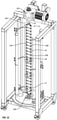
- mixing system 10 comprises a docking station 12, a container station 14 that removably docks with docking station 12, a container assembly 16 ( Figure 2 ) that is supported by container station 14, and a drive shaft 17 ( Figure 3 ) that extends between docking station 12 and container assembly 16.
- Container assembly 16 houses the fluid that is mixed.
- container assembly 16 comprises a container 18 having a side 20 that extends from an upper end 22 to an opposing lower end 24. Upper end 22 terminates at an upper end wall 33 while lower end 24 terminates at a lower end wall 34. Container 18 also has an interior surface 26 that bounds a compartment 28. Compartment 28 is configured to hold a fluid.
- container 18 comprises a flexible and collapsible bag that is comprised of a flexible, water impermeable material such as a low-density polyethylene or other polymeric sheets of film having a thickness in a range between about 0.1 mm to about 5 mm with about 0.2 mm to about 2 mm being more common.
- the polymeric film can have a thickness that is at least or less than 0.02 mm, 0.05 mm, 0.1 mm, 0.2 mm, 0.5 mm, 1 mm, 2 mm, 3 mm or in a range between any two of the foregoing. Other thicknesses can also be used.
- the film is typically sufficiently flexible that it can be rolled into a tube without plastic deformation and/or can be folded over an angle of at least 90°, 180°, 270°, or 360° without plastic deformation.
- the material can be comprised of a single ply material or can comprise two or more layers which are either sealed together or separated to form a double wall container. Where the layers are sealed together, the material can comprise a laminated or extruded material.
- the laminated material comprises two or more separately formed layers that are subsequently secured together by an adhesive.
- the laminated and extruded films typically have between 1-9 layers and more commonly between 3-9 layers.
- the films used can commonly have a number of layers that is at least or less than 1, 3, 5, 7, or 9 layers or in a range between any two of the foregoing.
- the extruded film can be a cast film such as a multi-layer co-extruded cast film.
- extruded material examples include the Thermo Scientific CX3-9 and Thermo Scientific CX5-14 films available from Thermo Fisher Scientific.
- the material can be approved for direct contact with living cells and be capable of maintaining a solution sterile. In such an embodiment, the material can also be sterilizable such as by ionizing radiation.
- container 18 can comprise a two-dimensional pillow style bag.
- container 18 can be formed from a continuous tubular extrusion of polymeric material that is cut to length. The ends can be seamed closed or panels can be sealed over the open ends to form a three-dimensional bag.
- Three-dimensional bags not only have an annular side wall but also a two dimensional top end wall and a two dimensional bottom end wall.
- Three dimensional containers can comprise a plurality of discrete panels, typically three or more, and more commonly four or six. Each panel is substantially identical and comprises a portion of the side wall, top end wall, and bottom end wall of the container. Corresponding perimeter edges of each panel are seamed together.
- the seams are typically formed using methods known in the art such as heat energies, RF energies, sonics, or other sealing energies.
- the panels can be formed in a variety of different patterns. Further disclosure with regard to one method of manufacturing three-dimensional bags is disclosed in United States Patent Publication No. US 2002-0131654 A1, published September 19, 2002 .
- container 18 can be manufactured to have virtually any desired size, shape, and configuration.
- container 18 can be formed having compartment 28 sized to be greater than, smaller than or equal to 10 liters, 30 liters, 100 liters, 250 liters, 500 liters, 750 liters, 1,000 liters, 1,500 liters, 3,000 liters, 5,000 liters, 10,000 liters or other desired volumes.
- the size of compartment 28 can also be in the range between any two of the above volumes.
- container 18 can be any shape, in one embodiment container 18 is specifically configured to be generally complementary to the chamber on container station 14 in which container 18 is received so that container 18 is properly supported within the chamber.
- container 18 is depicted as a flexible bag, in alternative embodiments it is appreciated that container 18 can comprise other forms of collapsible containers or semi-rigid containers. Container 18 can also be transparent or opaque.
- Each of ports 30-32 communicate with compartment 28.
- container 18 can be formed with any desired number of ports 30-32 and that ports 30-32 can be formed at any desired location on container 18.
- Ports 30-32 can be the same configuration or different configurations and can be used for a variety of different purposes.
- ports 30 can be coupled with fluid lines for delivering media, cell cultures, and/or other components into container 18 and withdrawing fluid from container 18.
- Ports 30 can also be used for delivering gas to container 18, such as through a sparger, and withdrawing gas from container 18.
- Ports 30-32 can also be used for coupling probes and/or sensors to container 18.
- ports 30-32 can be used for coupling probes such as temperatures probes, pH probes, dissolved oxygen probes, and the like.
- Various optical sensors and other types of sensors can also be attached to ports 30-32. Examples of ports 30-32 and how various probes, sensors, and lines can be coupled thereto is disclosed in United States Patent Publication No. 2006-0270036, published November 30, 2006 and United States Patent Publication No. 2006-0240546, published October 26, 2006 .
- Ports 30-32 can also be used for coupling container 18 to secondary containers, to condenser systems, and to other desired fittings.
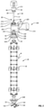
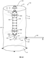
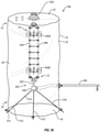
- Container assembly 16 further comprises a mixing assembly 40.
- mixing assembly 40 comprises a first rotational assembly 42A mounted on upper end wall 33, a second rotational assembly 42B mounted on lower end wall 34, elongated and flexible first and second drive lines 44A and 44B that extend between rotational assemblies 42A and 42B.
- a plurality of ties 45 extend between drive lines 44A and 44B at spaced apart locations along the length of drive lines 44A and 44B.
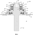
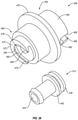
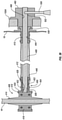
- rotational assembly 42A comprises an outer casing 50 that includes an annular body 51 having a passage that extends therethrough, an annular sealing flange 52 that outwardly projects from a first end of body 51 and an annular mounting flange 53 that outwardly projects from a second end of body 51.
- a hub 54 is rotatably disposed within outer casing 50.
- One or more bearing assemblies 55 can be disposed between outer casing 50 and hub 54 to permit free and easy rotation of hub 54 relative to casing 50.
- one or more seals 56 can be disposed between outer casing 50 and hub 54 so that during use an aseptic seal can be maintained between outer casing 50 and hub 54 as hub 54 rotates relative to outer casing 50.
- Hub 54 has a first end 58 that is disposed outside of container 18 and an opposing second end 60 that is disposed within container 18.
- An engaging portion is formed on first end 58 and is configured to engage with drive shaft 17 ( Figure 3 ).
- the engaging portion is depicted as an opening 66, such as in the form of a recessed socket, having a polygonal or other non-circular transverse cross section that is configured to mate to an end of drive shaft 17 so that rotation of drive shaft 17 facilitates rotation of hub 54.
- Other engagements between drive shaft 17 and hub 54 can also be used.
- Rotational assembly 42A is secured to container 18.
- container 18 has an opening 74 extending through upper end wall 33.
- Sealing flange 52 of outer casing 50 is sealed, such as by welding or adhesive, around the perimeter bounding opening 74 so that hub 54 communicates with compartment 28.
- Flange 52 can be welded on the interior or exterior surface of container 18.
- outer casing 50 is fixed to container 18 but hub 54, and thus also drive lines 44, can freely rotate relative to outer casing 50 and container 18.
- sealing opening 74 compartment 28 is sealed closed so that container 18 can be used in processing sterile fluids.
- rotational assembly 42B can have the same configuration as rotational assembly 42A and can be mounted to lower end wall 34 of container 18 in the same manner that rotational assembly 42A is mounted to container 18.
- drive shaft 17 ( Figure 3 ) is used to engage and rotate hub 54 of rotational assembly 42A.
- a separate drive shaft could also be used to engage and rotate hub 54 of rotational assembly 42B.
- hub 54 of rotational assembly 42A need not be engaged and rotated by drive shaft 17 but rather hub 54 of rotational assembly 42B can be solely rotated by a dive shaft extending up from the bottom of container assembly 16 to facilitate rotation of drive lines 44.
- hub 54 of rotational assembly 42B need not be directly engaged and rotated by a separate drive shaft and thus opening 66 ( Figure 4 ) on hub 54 of rotational assembly 42B can be eliminated.
- Each drive line 44 is elongated and extends from a first end 70 to an opposing second end 72.
- Drive lines 44 can be made from a variety of different flexible materials and can have different configurations.
- drive lines 44 can be made from a braded or woven material such as cable, cord or rope.
- the braded material can be made from a plurality of different strands that are comprised of metal, polymer, composite or other materials that have desired strength and flexibility properties and can be sterilized.
- the strands can be made from metal like stainless steel or a polymer like ultra-high molecular weight polyethylene (UHMwPE) such as that sold under the trademark DYNEEMA.
- UHMwPE ultra-high molecular weight polyethylene
- drive lines 44 can be made from a flexible tube, a single solid core line, a linkage, such as a chain or a linkage of universal joints, or other flexible or hinged members made from any of the above discussed materials.
- the diameter of drive lines 44 is in part dependent upon the materials used to make the drive lines and the size of the system. However, in some embodiments, the maximum or minimum diameter of each drive line 44 can be greater than, less than, or equal to 2 mm, 4 mm, 6 mm, 8 mm, 10 mm, 15 mm, or 20 mm or in a range between any two of the foregoing. Other dimensions can also be used.
- the term "diameter,” whether in reference to the size of a drive line or other component (e.g., an opening), is not limited to the measurement of circular or spherical components. Rather, whether circular, oval or oblong, rectangular, angle or jagged, or a combination thereof, the diameter of the component refers to a (cross-sectional) measurement between opposing sides and/or the (maximum or minimum) distance between the opposing sides.
- At least a portion of the length of each drive line 44 is sufficiently flexible so that the flexible portion of each drive line 44 can be twisted under torsion about a longitudinal axis of each drive line 44 over an angle of at least 15°, 25°, 45°, 90°, 180°, 360°, 720° or more without plastic deformation of drive line 44.
- at least a portion of the length of each drive line 44 is sufficiently flexible so that the flexible portion of each drive line 44 can be bent or folded relative to a linear longitudinal axis of drive line 44 over an angle ⁇ ( Figure 3 ) of at least 15°, 25°, 45°, 90°, 135°, 180°, 270°, or 360° or more without plastic deformation of drive line 44.
- each drive line 44 or the flexible portion of each drive line 44 can have a bend radius wrapped 180° without plastic deformation in a range between about 2 cm to about 100 cm with about 6 cm to about 80 cm, about 10 cm to about 60 cm, or about 10 cm to about 40 cm being more common. Other flexibilities can also be used.
- the entire length of each drive line 44 need not be flexible. For example, a percentage of the entire length of each drive line 44, such as at least or not to exceed 30%, 40%, 50%, 60%, 70%, 80%, 90% or more of drive line 44, could have the above flexible properties while the remainder is rigid or at least more rigid. In other embodiments, the entire length of drive lines 44 can have the desired flexible properties.
- each tie 45 comprises an elongated brace 190 having a first end 191 and an opposing second end 192. Disposed at opposing ends 191 and 192 are U-shaped guides 193A and 193B, respectively. Each guide 193 has a U-shaped seat 194 configured to receive a drive line 44 and has an outside shoulder 195.
- Each tie 45 also includes a pair of fasteners 196A and 196B.
- Each fastener 196 comprises a back 198 and a pair of arms 200A and B projecting therefrom.
- a lip 202A and B inwardly projects from each arm 200A and B, respectively.
- a channel 203 is bounded between arms 200.
- drive lines 44A and 44B are received within seat 194 of guides 193A and B, respectively.
- Fasteners 196A and B are then passed over guides 193A and B, respectively, so that drive lines 44A and 44B are received within corresponding channels 203.
- Fasteners 196 are advanced until lips 202 resiliently snap behind outside shoulder 195. In this position, fasteners 196 are locked to guides 193 and drive lines 44 are compressed between fasteners 196 and guides 193 so that tie 45 is held fixed on each drive line 44A and 44B. This process is repeated for subsequent ties 45 at spaced apart locations along drive lines 44A and 44B.
- ties 45 can have a variety of different configurations and can be attached to drive lines 44A and B using a variety of different fastening techniques.
- ties 45 could be crimped, welded, over molded, or adhered to drive lines 44.
- threaded fasteners, clamps, press fit connections, screws, bolts, or the like can be used to secure ties 45 to drive lines 44A and B.
- each drive line 44A and B can each comprise a plurality of separate line portions where free ends of adjacent line portions are separately secured to opposing sides of each tie 45.
- the distance at which drive lines 44A and B are held spaced apart by ties 45 can vary based on factors such as the size of container 18 and the speed at which drive lines 44 are rotated. In some common embodiments, ties 45 are configured to maintain drive lines 44 spaced apart by a distance greater than, less than, or equal to 2 cm, 4 cm, 6 cm, 8 cm, 11 cm, 14 cm, 17 cm, 20 cm, 25 cm or in a range between any two of the foregoing. Other dimensions can also be used. The spacing between ties 45 can also vary based on system parameters and operating conditions.
- a plurality of ties 45 are spaced apart along the length of drive lines 44 by a distance greater than, less than, or equal to 5 cm, 8 cm, 11 cm, 14 cm, 17 cm, 20 cm, 25 cm or in a range between any two of the foregoing. The spacing can be consistent or varied between different pairs of ties 45.
- mount 206A is used to secure first ends 70 of drive lines 44 to hub 54 of rotational assembly 42A while a mount 206B is used to secure second ends 72 of drive lines 44 to hub 54 of rotational assembly 42B.
- mount 206A comprises U-shaped arms 208A and 208B each having a central portion 209 that is received within corresponding slots 207A and 207B formed on opposing sides of second end 60 of hub 54.
- Fasteners 211 such as screws, bolts, rivets or the like, secure arms 208A and B together so that hub 54 is sandwiched therebetween and securely fixed to arms 208.
- An elongated support 212 having slots 213A and B formed on opposing ends is also sandwiched between arms 208A and B so as to extend between the opposing ends of arms 208. Support 212 is also secured to arms 208A and B by fasteners 211.
- Mounted on first end 70 of each drive line 44A and B is a bushing 214A and 214B, respectively.
- Bushing 214 can be secured to drive lines 44 using conventional techniques such as welding, over molding, crimping, press fit, fastener or the like.
- Bushing 214A and B are rotatably secured within slots 213A and B, respectively, on support 212.
- Support 212 can be sized to that support 212 holds first ends 70 of drive lines 44 at the spaced apart distance discussed above with regard to ties 45.
- drives lines 44 are secured to hub 54 so that as hub 54 is rotated, drive lines 44 concurrently rotate.
- drive lines 44 rotate about a longitudinal axis extending through hub 54 ( Figure 5 ).
- First ends 70 of drive lines 44 can also rotate relative to mount 206 so as to help reduce localized stress on drive lines 44 during operation.
- drive lines 44 can be secured to hub 54 using a variety of different techniques and configurations.
- mount 206 can be eliminated and first end 70 of drive lines 44 can be secured directly to hub 54.
- mount 206 can have a variety of different configurations.
- arms 208 can be eliminated and support 212 connected directly to hub 54 such as by welding, fasteners, press fitting, over molding or being integrally formed as a unitary piece with hub 54.
- Figure 10 shows mounts 206C and 206D each in the form of an elongated support outwardly extending from hubs 54 of rotational assemblies 42A and 42B, respectively.
- bushings 214 can be eliminated and first and second ends 70 and 72 of drive lines 44 can be securely fixed to opposing ends of supports 212, securely fixed directly to hubs 54 or securely fixed to other mount configurations. Other configurations can also be used.
- mount 206B can have the same configurations as mount 206A and can be used in the same way to secure second ends 72 of drive lines 44 to hub 54 of rotational assembly 42B.
- Like elements between mount 206A and B are identified by like reference characters and the same alternatives as discussed above with regard to mount 206A are also applicable to mount 206B.
- mixing assembly 40 also includes a plurality of mixing elements secured to drive lines 44A and B.
- each mixing element can comprise an impeller 46 having a central hub 76 that spans between drive lines 44A and B and has a plurality of blades 78 radially outwardly projecting therefrom.
- Hub 76 can have a variety of different configurations. For example, as depicted in Figure 7 , hub 76 can simply comprise a tie 45 secured to drives lines 44A and B as discussed above and having a flange 77 outwardly projecting therefrom from which blades 78 project. The alternative tie designs discussed above and used in conjunction with flange 77 or without flange 77 can also be used.
- tie 45 can be eliminated from hub 76 and hub 76 can simply comprise a plate or other structure that spans between drive lines 44A and B and is secured to drive lines 44 at desired locations by crimping, welding, adhesive or by using a set screw, clamp, fastener or other securing techniques.
- each drive line 44A and B can each comprise a plurality of separate line portions where free ends of adjacent line portions are separately secured to opposing sides of each impeller 46. Other configurations can also be used.
- blades 78 can be mounted on hub 76.
- Blades 78 can be rigidly fixed to hub 76 or can be pivotably coupled to hub 76.
- Examples of impellers having blades that are hingedly coupled to a hub are disclosed in US Patent Publication No. 2015/0117142, published April 30, 2015 .
- three impellers 46 are shown in Figure 3 , it is appreciated that impellers 46 can be positioned at any position along the length of drive lines 44 and that any number of mixing elements/impellers 46, such as 1, 2, 4, 5, or more, can be positioned along drive lines 44.
- the inventive system can be easily customized by choosing the type of mixing element/impeller, the number of mixing elements/impellers, and the location of mixing elements/impellers that are placed along drive lines 44 during assembly.
- Impellers 46 disclosed herein and the alternatives discussed relative thereto are examples of mixing elements.
- Mixing elements also include other structures that can be mounted on drive lines 44 that can function to mix fluid when rotated but which would not normally be considered an impeller.
- Examples of such other mixing elements can include paddles, stir bars, fins, blades, baffles and other structures that can be mounted directly or indirectly to drive lines 44 for use in mixing.
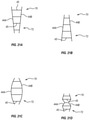
- FIG. 8 Depicted in Figure 8 is one alternative embodiment of an impeller 46A that includes a tie 45 having blades 80A and 80B vertically outwardly projecting therefrom.
- An impeller 46B is also depicted that includes a tie 45 having blades 81A and 81B laterally outwardly projecting therefrom.
- Alternative configurations for tie 45 as discussed above, can also be used can also be used in conjunction with blades 80 and 81.
- mixing assembly 40 can exclude the use of any impellers or mixing elements. For example, when relatively small containers 18 are used, drive lines 44 and ties 45 can be independently sufficient to achieve the necessary mixing.
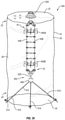
- Figure 2 shows container assembly 16 including mixing assembly 40 in a relaxed vertically extended state.
- Drive lines 44A and B are laterally spaced apart, i.e., drive lines 44 are disposed side-by-side with first ends 70 being disposed toward upper end 22 of container 18 and second ends 72 being disposed toward lower end 24 of container 18.
- the full length of drive lines 44 are disposed within compartment 28 of container 18, drive lines 44 are spaced apart a substantially constant distance along their full lengths, and drive lines 44 are disposed in substantially parallel alignment.
- the term "substantially” as used herein is intended to account for slight offsets resulting from conventional manufacturing processes and tolerances.
- drives lines 44 need not have a constant separation along their length and need not be in parallel alignment when in the vertically extended relaxed state.
- mixing assembly 40 is used in conjunction with drive shaft 17.
- Drive shaft 17 has a first end 84 and an opposing second end 86.
- Formed at first end 84 is a frustoconical engaging portion 88 that terminates at a circular plate 90.
- Notches 92 are formed on the perimeter edge of circular plate 90 and are used for engaging drive shaft 17 with a drive motor assembly as will be discussed below.
- driver portion 68 Formed at second end 86 of drive shaft 362 is driver portion 68.
- Driver portion 68 has a non-circular transverse cross section complementary to opening 66 of hub 54 ( Figure 4 ) so that it can facilitate locking engagement within opening 66 of hub 54.
- driver portion 68 has a polygonal transverse cross section.
- other non-circular shapes can also be used.
- other releasable locking mechanisms can be used to engage drive shaft 17 with hub 54. For example, a bayonet connection, threaded connection, clamp, or fastener could be used.
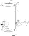
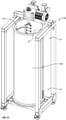
- container station 14 comprises a support housing 100 supported on a cart 102.
- Support housing 100 has a substantially cylindrical sidewall 104 that extends between an upper end 106 and an opposing lower end 108.
- Lower end 108 has a floor 110 mounted thereto.
- support housing 14 has an interior surface 112 that bounds a chamber 114.
- An annular lip 116 is formed at upper end 106 and bounds an opening 118 to chamber 114.
- chamber 114 is configured to receive container assembly 16 so that container 18 is supported therein.
- support housing 100 is shown as having a substantially cylindrical configuration, in alternative embodiments support housing 100 can have any desired shape capable of at least partially bounding a compartment.
- sidewall 104 need not be cylindrical but can have a variety of other transverse, cross sectional configurations such as square, rectangular, polygonal, elliptical, or irregular.
- support housing 100 can be scaled to any desired size.
- support housing 100 can be sized so that chamber 114 can hold a volume of less than 50 liters, more than 1,000 liters or any of the other volumes or range of volumes as discussed above with regard to container 18.
- Support housing 100 is typically made of metal, such as stainless steel, but can also be made of other materials capable of withstanding the applied loads of the present invention.
- sidewall 104 of support housing 100 has an enlarged access 120 at lower end 108 so as to extend through sidewall 104.
- a door 122 is hingedly mounted to sidewall 104 and can selectively pivot to open and close access 120.
- a latch assembly 124 is used to lock door 122 in the closed position.
- An opening 126 which is depicted in the form of an elongated slot, extends through door 122. Opening 126 is configured to align with ports 31 ( Figure 2 ) of container assembly 16 when container assembly 16 is received within chamber 114 so that ports 31 project into or can otherwise be accessed through opening 126.
- a line for carrying fluid or gas will be couple with port 31 and can extend out of chamber 114 through opening 126.
- any number of ports 31 can be formed on container 18 and thus any number of separated lines can pass out through opening 126 or through other openings formed on support housing 100.
- different types of probes, sensors, inserts, connectors, or the like may be coupled with ports 31 which can be accessed through opening 126 or other openings.
- means are provided for regulating the temperature of the fluid that is contained within container 18 when container 18 is disposed within support housing 100.
- sidewall 104 can be jacketed so as to bound one or more fluid channels that encircle sidewall 104 and that communicate with an inlet port 130 and an outlet port 132.
- a fluid such as water or propylene glycol, can be pumped into the fluid channel through inlet port 130. The fluid then flows in a pattern around sidewall 104 and then exits out through outlet port 132.
- the temperature of support housing 100 can be regulated which in turn regulates the temperature of the fluid within container 18 when container 18 is disposed within support housing 100.
- electrical heating elements can be mounted on or within support housing 100. The heat from the heating elements is transferred either directly or indirectly to container 18.
- other conventional means can also be used such as by applying gas burners to support housing 100 or pumping the fluid out of container 18, heating the fluid and then pumping the fluid back into container 18.
- the means for heating can be used to heat the culture within container 18 to a temperature in a range between about 30° C to about 40° C. Other temperatures can also be used.
- a retainer 140 is centrally mounted on the interior surface of floor 110 of support housing 100.
- Retainer 140 has a U-shaped slot 142 that is bounded by an inwardly projecting U-shaped catch lip 144.
- Retainer 140 is configured so that when container assembly 16 is received within chamber 114 of support housing 100, second rotational assembly 42B can be manually slid into slot 142 ( Figure 3 ) so that mounting flange 53 of second rotational assembly 42B is captured within slot 142 below catch lip 144, thereby securing second rotational assembly 42B to retainer 140 and preventing rotational assembly 42B from being raised vertically relative to retainer 140.
- retainer 140 is to releasably engage second rotational assembly 42B and, as such, the configuration of retainer 140 can change as the configuration of rotational assembly 42B changes.
- retainer can have different slot configurations and can be in the form of a variety of different clamps, ties, fasteners or the like that are designed to engage rotational assembly 42B in its present form or in a modified form.
- second rotational assembly 42B can be attached to retainer 140 by reaching in through access 120 on sidewall 104 of support housing 100.
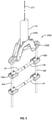
- docking station 12 comprises a stand 134, an adjustable arm assembly 136 coupled to stand 134 and a drive motor assembly 300 mounted on arm assembly 136.
- Drive motor assembly 300 is used in conjunction with drive shaft 17 ( Figure 3 ) and can be used for mixing and/or suspending a culture, solution, suspension, or other liquid within container 18 ( Figure 2 ).
- drive motor assembly 300 comprises a housing 304 having a front face 305 that extends from a top surface 306 to an opposing bottom surface 308.
- An opening 310 extends through housing 304 from top surface 306 to bottom surface 308.
- a tubular motor mount 312 is rotatably secured within opening 310 of housing 304. Upstanding from motor mount 312 is a locking pin 316.
- a drive motor 314 is mounted to housing 304 and engages with motor mount 312 so as to facilitate select rotation of motor mount 312 relative to housing 304.
- Drive shaft 17 is configured to pass through motor mount 312 so that engaging portion 88 of drive shaft 17 is retained within motor mount 312 and locking pin 316 of motor mount 312 is received within notch 92 of drive shaft 17.
- rotation of motor mount 312 by drive motor 314 facilitates rotation of drive shaft 17.
- a removable cap 313 is used to hold drive shaft 17 on motor mount 312. Further discussion of drive motor assembly 300 and how it engages with drive shaft 17 and alternative designs of drive motor assembly 300 are discussed in US Patent Publication No. 2011/0188928, published August 4, 2011 .
- arm assembly 136 is used to adjust the position of drive motor assembly 300 and thereby also adjust the position of drive shaft 17.
- Arm assembly 136 comprises a first arm 320 mounted to stand 134 that vertically raises and lowers, a second arm 322 mounted to the first arm 320 that slides horizontally back and forth, and a third arm 324 mounted to second arm 322 that rotates about a horizontal axis 326.
- Drive motor assembly 300 is mounted to third arm 324. Accordingly, by movements of arms 320, 322, and/or 324, drive motor assembly 300 can be positioned in any desired location or orientation relative to support housing 100 and container assembly 16. For example, drive motor assembly 300 can be positioned so that drive shaft 17 is centered and vertically oriented when connected with container assembly 16.
- drive shaft 17 can be oriented at an angle, such as in a range between 10° to 30° from vertical when connected with container assembly 16. Further discussion and alternative embodiments with regard to docking station 12, arm assembly 136, and container station 14 is provided in US Patent Publication No. 2011/0310696, published December 22, 2011 .
- container station 14 and docking station 12 are removably coupled together as shown in Figure 1 .
- One example of how docking station 12 and container assembly 16 can be coupled together is disclosed in US Patent Publication No. 2011/0310696 . Other methods can also be used.
- container assembly 16 ( Figure 2 ) is positioned within chamber 114 of support housing 100 and second rotational assembly 42B is secured to retainer 140 as discussed above.
- housing 304 of drive motor assembly 300 has a U-shaped receiving slot 330 that is recessed on a front face 305 and bottom surface 308 so as to communicate with opening 310 extending through housing 304.
- Receiving slot 330 is bounded by an inside face 332 on which a U-shaped catch slot 334 is recessed.
- a door 336 is hingedly mounted to housing 304 and selectively closes the opening to receiving slot 330 from front face 305.
- rotational assembly 42A is horizontally slid into receiving slot 330 from front face 305 of housing 304 so that mounting flange 53 that is radially outwardly extending from the upper end of rotational assembly 42A is received and secured within catch slot 334.
- First rotational assembly 42A is advanced into receiving slot 330 so that opening 66 of rotational assembly 42A aligns with the passage extending through motor mount 312.
- Door 336 ( Figure 1 ) is then moved to the closed position and secured in place by a latch or other locking mechanism so that first rotational assembly 42A is locked to drive motor assembly 300.
- Rotational assemblies 42A and 42B are now secured to drive motor assembly 300 and retainer 140, respectively, as shown in Figure 10 .
- Arm assembly 136 ( Figure 5 ) can now be used to add slack or tension to flexible drive lines 44 by lowering or raising drive motor assembly 300 to which rotational assembly 42A is coupled.
- arm assembly 136 can be used to adjust the orientation of drive lines 44. For example, by adjusting the position of drive motor assembly 300, drive lines 44 can be adjusted so as to be centered within support housing 100 and vertically oriented or drive lines 44 can be oriented at an angle, such as in a range between 10° to 30° from vertical. Other positions and orientations can also be used.
- drive shaft 17 can be advanced down through motor mount 312 of drive motor assembly 300 and into opening 66 of rotational assembly 42A so that drive shaft 17 engages with hub 54.
- Liquid and other components can be delivered into container 18.
- container 18 is functioning as a bioreactor or fermentor, cells or microorganisms along with media, nutrients and other standard components can be added to container 18.
- other liquids such as chemicals, medications, beverages, food products, or the like can also be processed.
- Drive motor 324 can be activated so as to rotate drive shaft 17 which in turn begins the rotation of hub 54 of first rotational assembly 42A, drive lines 44, and impellers 46. Rotation of drive lines 44 and impellers 46 facilitates mixing and/or suspension of the liquid and components contained within container 18. Where needed, the liquid can be concurrently sparged with a gas while mixing.
- Drive lines 44 are typically sized so that they can be slack when container assembly 16 is secured to support housing 14 and drive motor assembly 300.
- the slack or tension in drive lines 44 can be adjusted by using arm assembly 136 ( Figure 9 ) to selectively raise or lower first rotational assembly 42A.
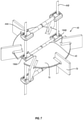
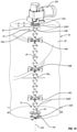
- drive lines 44 are slack and made of a flexible material, drive lines 44 will twist into a helical configuration along their length during operation as shown in Figure 10 , i.e., drive lines 44A and B form a double stranded helix. That is, first end 70 of drive lines 44 begin to rotate concurrently with the rotation of hub 54 of first rotational assembly 42A.
- drive lines 44A and B begin to twist into the helical configuration during operation so as to cause each drive line 44 to come under torsion.
- the vertical length of drive lines 44 is shorted.
- second end 72 of drive lines 44 are restrained from being raised vertically both because of the fluid within container 18 and because of retainer 140, drive lines 44 can twist to the extent that slack is removed from drive lines 44 but lines 44 are thereafter restrained from being further shortened along the vertical length which places drive lines 44 in tension. Once sufficient torsion is placed on drive lines 44 to overcome the fluid resistance and friction force, the entire length of drives lines 44 rotate within container 18.
- the sections of drive lines 44 between first rotational assembly 42A and first impeller 46A is generally subject to the highest torsion force because that section of drive lines 44 is subjected to the resistance produced by the portion of mixing assembly 40 that extends from impeller 46A to second rotational assembly 42B, i.e., includes each of impellers 46A-46C.
- the section of drive lines 44 between impeller 46C and rotational assembly 42B is only subject to the resistance produced by mount 206B and hub 54 of second rotational assembly 42B.
- the torsion on the lower section of drives lines 44 is less than the torsion on the upper section of drive lines 44.
- Drive lines 44 are, in part, specifically designed to twist into a helical configuration to minimize the tension and torsion force that lines 44 are subject to during operation. That is, as drive lines 44 twist into the helical configuration, as discussed above and depicted in Figure 10 , a portion of the torsion and tension that is applied to drive lines 44 is converted to a vector force that tries to push drive lines 44A and B together. This vector force is applied to the opposing ends of ties 45 which, as a result, place ties 45 under compression. Ties 45, however, are sufficiently rigid and have sufficient strength to carry the compressive load without failure and thus maintain the spacing between drive lines 44.
- drive lines 44 have a length and flexibility that permits drive lines 44 to twist into a helical configuration so that an inside angle ⁇ 1, as shown in Figure 10 , is formed between lines 44 and a plane 204 that extends normal to an axis of rotation 205 of drive lines 44.
- Angle ⁇ 1 is typically in a range between 20° and 70° and more commonly in a range between 30° and 60° or 35° and 55°. In other embodiments, the angle ⁇ 1 can be greater than, less than, or equal to 20°, 30°, 40°, 50°, 60°, 70° or in a range between any two of the foregoing. Other angles can also be used.
- Ties 45 also function to maintain spacing between drive lines 44 which helps prevent drive lines 44 from spooling up on themselves, i.e., twisting together, which can destabilize the mixing and result in failure in the mixing assembly.
- angle ⁇ 1 gets too small, there is an increased risk that the combined drive lines 44 can still spool or twist together.
- container assembly 16 can be configured and operated within support housing 100 so that drive lines 44 and the helix formed thereby remain substantially vertically orientated prior to and during operation.
- retainer 140 could be positioned offset from the center of the floor of support housing 100 and second rotational assembly 42B could be complementarily offset from the center of the floor of container 18.
- arm assembly 136 ( Figure 9 ) can be used to adjust the angle and lateral position of first rotational assembly 42A.
- the helix formed by drive lines 44 can be set to operate at an angle relative to vertical that is substantially less than, greater than, or equal to 5°, 10°, 15°, 20° or 25° or in a range between any two of the foregoing.
- the inventive mixing assembly of having at least two flexible drive lines 44 held spaced apart during mixing has a number of unique advantages.
- the mixing assembly remains flexible so that container assembly 16 can be collapsed and folded upon itself for easy sterilization, transportation and storage.
- the folded and collapsed container assembly can also be easily inserted into chamber 114 of support housing 100 even in low ceiling facilities.
- the inventive system also solves many of the problems encounter by using the single flexible drive line system disclosed in International Publication No. WO 2013/151733 , which is referenced in the background section of the present application.
- one of the problems with the single flexible drive line system is that during operation the single flexible drive line can easily spool up on itself, i.e., twist into a knot at one or more locations along the length of the drive line. This spooling can result in failure of the system, i.e., rupture of the drive line and/or bag, and also disrupts uniform mixing of the fluid.
- the single drive line is subject to very high torsion and tension loads during fluid mixing.
- the inventive system having at least two laterally spaced apart drive lines 44 that concurrently rotate about a common axis of rotation significantly decreases the chance that drive lines 44 can spool up or twist together. Furthermore, as a result of spaced apart drive lines 44 twisting into a helical configuration during operation, the tension and torsion loads placed on drive lines 44 are reduced relative to the tension and torsion loads that would be placed on a single drive line. As a result, relative to a single drive line system, drive lines 44 can be made thinner, more flexible and/or with less expensive material so as to make the overall system lighter, more flexible and/or less expensive while maintaining high efficiency and reliability.
- a second drive shaft could be coupled with hub 54 of second rotational assembly 42B through a hole formed in floor 110 of support housing 100.
- a second drive shaft could be coupled with hub 54 of second rotational assembly 42B through a hole formed in floor 110 of support housing 100.
- the opposing ends of drive lines 44 could twist in opposite directions toward the middle of drive lines 44 or the rotation of hubs 54 could be staggered, i.e., one starts rotating before the other, so that again a common helix is formed along the length of drive lines 44.
- docking station 12 which includes arm assembly 136.
- docking station 12 can be coupled with any number of different container stations 14 having a container assembly 16 therein.
- docking station 12 can be eliminated and arm assembly 136 can be mounted directly onto support housing 100.
- Alternative examples of arm assemblies and how they can be mounted onto support housing 100 is disclosed in US Patent Publication No. 2013/0101982, published on April 25, 2013 .
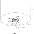
- retainer 140 is mounted on the interior surface of floor 110 of support housing 100 for engaging with second rotational assembly 42B ( Figure 2 ).
- a retainer 140A can be mounted on the exterior surface of floor 110 of support housing 100.
- a hole 148 centrally extends through floor 100 so as to communicate with chamber 114.
- retainer 140A has an opening 149 that is bounded between a body 150 and a locking arm 152 hingedly mounted thereto. During use, with locking arm 152 in an open position, the free end of second rotational assembly 42B ( Figure 2 ) is passed down through hole 148 so as to be received within opening 149.
- Second rotational assembly 42B can be configured to pass down through hole 148 and engage with the retainer.
- means are provided for holding the lower end 24 of container 18 stationary while flexible drive lines 44 is rotated within compartment 28 of container 18.
- this means includes retainer 140 mounted on the interior surface of floor 110, retainer 140A mounted on the exterior surface of floor 110 retainer 140A mounted on a separate structure located below floor 110, and other configurations of retainers that can be placed in the above locations.
- the means for holding can also comprise any number of conventional fastening techniques and separable interlocking structures that can be used to secure lower end 24 of container 18 within support housing 100.
- Such structures can include securing second rotational assembly 42B or some other structure secured to container 18 to support housing using screws, bolts, hooks, Velcro, i.e., hook and loop material, threaded connection, bayonet connection, clamps or the like.
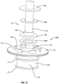
- FIG 12 Depicted in Figure 12 is an alternative embodiment of a mixing assembly 40A. Like elements between mixing assemblies 40 and 40A are identified by like reference characters.
- Mixing assembly 40A comprises a first rotational assembly 160A and a second rotational assembly 160B with drive lines 44A and B extending therebetween.
- First rotational assembly 160A has substantially the same configuration as first rotational assembly 42A and includes outer casing 50 having sealing flange 52 for securing to container 18 and mounting flange 53.
- First rotational assembly 160A has a hub 162 that rotates relative to casing 50. However, in contrast to having an opening 66 ( Figure 4 ) located at the end thereof, hub 162 includes an outwardly projecting stem 164 which forms another example of an engaging portion.
- Stem 164 has a non-circular transverse cross section, such as polygonal, so that a drive shaft 17A having a complementary socket 166, that replaces driver portion 68 ( Figure 3 ), can securely engage with and rotate hub 162.
- second rotational assembly 160B comprises an outer casing 168 that includes a cylindrical base 170 having one or more mounting flanges 171 radially outwardly projecting from a lower end thereof and an enlarged annular sealing flange 172 radially outwardly projecting from the upper end thereof.
- Base 170 and mounting flanges 171 are configured to be engaged by retainer 140A ( Figure 12 ).
- Sealing flange 172 is configured to secure to container 18, such as by welding, in the same manner as sealing flange 52 ( Figure 2 ).
- Outer casing 168 has a top surface 174 on which a cylindrical blind pocket 176 is formed.
- Second rotational assembly 160B also includes a hub 178 having a base 180.
- Hub 178 also includes an annular flange 182 encircling and radially outwardly projecting from a lower end of base 180.
- Flange 182 is configured so that it can be rotatably received within blind pocket 176.
- Annular bearings 184A and 184B, such as roller thrust bearings, are also received within pocket 176 on opposing sides of flange 184 so that hub 178 can freely rotate relative to outer casing 168.
- a cover plate 186 encircles hub 178 and is positioned over bearing 184A. Cover plate 186 is secured in place by engaging with locking fingers 188 that project from top surface 174 at spaced apart locations around pocket 176.
- cover plate 186 retains hub 178 within outer casing 168. It is appreciated that because pocket 176 is blind, it is not necessary to position a seal between hub 178 and outer casing 168, although a seal can be used if desired so as to prevent fluid from entering pocket 176. It is also appreciated that the rotational assemblies can have a variety of other configurations.
- Drive opposing ends 70 and 72 of drive lines 44A and B are connected to hubs 162 and 178, respectively, using mounts 206A and B. Other configurations of mounts discussed herein can be used or mounts 206 can be eliminated.
- Drive lines 44 are separated by ties 45 and have impeller 46 mounted thereon.
- Foam breaker 156 disposed at an upper end of hub 162 is a foam breaker 156.
- Foam breaker 156 includes a hub 157 secured to hub 162 and a bar 158 that outwardly projects from opposing sides of hub 157.
- Foam breaker 156 rotates concurrently with hub 162 to break up foam that is formed at the upper end of container 18. It is appreciated that foam breaker 156 can come in a variety of different configurations.
- means are provided for rotating first drive line 44A and second drive line 44B within compartment 28 of container 18.
- such means can comprise drive shaft 17, 17A that is configured to engage the hub of one of the rotational assemblies and also includes drive motor assembly 300 that rotates drive shaft 17, 17A.
- the means for rotating also includes other structures that can be used to rotate the hub of one of the rotation assemblies.
- the means could include a hub of a rotational assembly that projects out of container 18 and engages directly with drive motor assembly 300.
- Other configurations of drive shafts 17 and drive motor assemblies 300 having different interlocking features can also be used.
- the means also includes other non-drive shaft systems that can be used to rotate drive lines 44.
- a gear assembly, belt, drive wheel, or other structures can be used to rotate the hub.
- magnetic drive systems placed outside of container 18 and operating with a corresponding component disposed within container 18 and coupled with drive lines 44 can be used to magnetically rotate drive lines 44.
- the means can also comprise other conventional systems used to drive impellers, stir bars, mixing paddles, and other stirring elements.
- the mixing assemblies include two spaced apart drive lines 44A and 44B.
- a mixing assembly can be formed having three laterally spaced apart drive lines 44A-C that extend between rotational assemblies 42A and B ( Figure 2 ). In a vertically extending resting state, all three drive lines 44A-C can be disposed within a single plane and disposed in substantially parallel alignment.
- a single continuous tie can extend between all three drive lines 44A-C at spaced apart positions along the length of drive lines 44A-C or one set of ties 45 can be used to separate drive lines 44A and 44B while a different set of ties 45 can be used to separate drive lines 44A and 44C.
- spaced apart drive lines 44A-C need not be disposed within a single plane but can be laterally spaced apart in a triangular configuration where again drive lines 44A-C can extend between rotational assemblies 42A and B ( Figure 2 ).
- a mixing assembly can be formed having four laterally spaced apart drive lines 44A-D that extend between rotational assemblies 42A and B ( Figure 2 ).
- Drive lines 44A-D can be disposed in a square or rectangular configuration.
- mixing assemblies can be formed using other numbers of laterally spaced apart drive lines 44 such as 5, 6, 7, 8, 9 or more that can be disposed in a circular, polygonal, irregular or other configurations.
- ties 45 projecting normal or at right angles between drive lines 44. That is, ties 45 are disposed perpendicular to drive lines 44 when drive lines are vertically disposed. In alternative embodiments, however, ties 45 need not extend perpendicular to drive lines 44 but can project at an acute inside angle ⁇ 2 from each drive line 44A and B as depicted in Figure 17 .
- the acute angle ⁇ 2 can be greater than, less than, or equal to 80°, 70°, 60°, 50°, 40°, 30°, or 20° or in a range between any two of the angles.
- ties 45 extending between drive lines 44 need not be straight but can have a variety of different configurations such as circular, X-shaped, U-shaped, V-shaped, curved, arced, or the like.
- one single continuous tie can extend along the length of drive lines 44 for holding spaced apart.
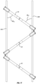
- depicted in Figure 18 is a single, continuous tie 45A that curves back and forth between drive lines 44A and B at spaced apart locations along the length of drive lines 45A and B.
- Openings 218 extend through tie 45A at the curved sections through which drive lines 45A and B can pass during assembly.
- Drive lines can then be freely movable within openings 218 or secured therein such as by crimping, adhesive, welding, fastener, press fit connection or the like.
- each drive line 44 can comprise a separate continuous drive line (such as depicted in Figure 3 ) or each drive line 44 can comprise a plurality of separate drive line sections that are coupled together.
- a drive line 44A1 is depicted as comprising a plurality of separate drive line sections 220 that are hingedly connected in series by a plurality of connectors 219A.
- connectors 219A are depicted as rings. In other embodiments, however, connectors 219A could come in a variety of different configurations such as crimps, hinges, balls, clamps, hooks, unions, or the like, which either rigidly or hingedly connect opposing ends of drive line sections 220 together.
- drive line sections 220 are typically made of a flexible material such as that previously discussed with regard to drive lines 44A and B.
- drive line sections 220 can be rigid or flexible. That is, even if drive line sections 220 are rigid, because the sections 220 are hingedly coupled together, the overall drive line 44A1 is flexible.
- a drive line 44B1 is also depicted as comprising a plurality of separate drive line sections 222 that are hingedly connected in series by a plurality of connectors 219B.
- Connectors 219B can be the same configuration and alternatives as discussed with connectors 219A.
- a plurality of spaced apart ties 45B extend between drive lines 44A1 and 44B1 at spaced apart locations along the length of drive lines 44A1 and 44B1.
- Ties 45B extend between connectors 219A and 219B and can be either rigidly or hingedly connected thereto.
- ties 45B could be replaced with ties 45C that extend directly between laterally spaced apart adjacent drive line sections 220 and 222 and are either hingedly or rigidly connected thereto.
- drive lines 44A and B could be integrally formed as one continuous line.
- a continuous line 224 is depicted that comprises drive line 44A and drive line 44B that both extend between first end 70 and opposing second end 72.
- Line 224 also includes a transition portion 225 that extends between first end 70 of drive lines 44A and 44B.
- drive line 44A, drive line 44B and transition portion 225 combine to form a single, continuous, unitary line, i.e., line 224.
- First ends 90 of lines 44 can still be connected to rotational assembly 42A such as by using one of the above described mounts or methods.
- Second ends 72 of lines 44 can remain separate and discrete and connected to rotational assembly 42B as discussed above.
- second ends 72 of lines can be connected together by transition portion 225 while first ends 70 remain separate and discrete.
- drive lines 44A and B can be part of a continuous loop.
- drive lines 44 are shown as being disposed in substantially parallel alignment when in an extended, relaxed, untwisted state. However, in alternative embodiments drive lines 44 need not be disposed in parallel alignment when in a relaxed state.
- drive lines 44 converge towards each other as they extend from first end 70 to second end 72 but are maintained laterally spaced apart by ties 45 extending therebetween.
- drive lines 44 diverge away from each other as they extend from first end 70 to second end 72.
- drive lines 44 outwardly curve in symmetrical arcs as they extend from first end 70 to second end 72.
- drive lines 44 extend in a changing pattern, such as a zigzag pattern, as they extend from first end 70 to second end 72. In still other embodiments, drive lines 44 can extend in other non-parallel patterns that are symmetrical, non-symmetrical, repeating or non-repeating.
- Fluid mixing system 10A comprises a container assembly 16A at least partially disposed within the compartment of a support housing 100A.
- Like elements between container assembly 16 and 16A and between support housing 100 and 100A are identified by like reference characters.
- disclosure and alternative embodiments as previously discussed with regard to container 16 and support housing 100 are also applicable to corresponding elements of container assembly 16A and support housing 100A.
- container assembly 16A comprises container 18 having flexible drive lines 44A and B disposed therein.
- First end 70 of flexible drive lines 44 are secured to upper end wall 33 of container 18 by rotational assembly 42A.
- mixing elements 400A and B Mounted on flexible drive lines 44 as spaced apart locations are mixing elements 400A and B.
- mixing element 400A and B can comprise an impeller or other types of mixing elements.
- container assembly 16A can comprise one, three, or four or more mixing elements 400.
- container assembly 16A has second end 72 of drive lines 44 suspended above lower end wall 34 and not connected thereto.
- container assembly 16A comprises a lateral support assembly 402.
- a hub 228 is rotatably mounted to lateral support assembly 402 while brace 206B secures second end 72 of drive lines 44 to hub 228.
- Lateral support assembly 402 comprises a retention assembly 404 having a first end 405 secured to side 20 of container 18 and an opposing second end 407 secured to hub 228.
- Lateral support assembly 402 also includes a support rod 406 that is selectively received and secured within retention assembly 404.
- Retention assembly 404 comprises a port fitting 410 at first end 405 that is coupled with side 20 of container 18, a receiver 408 at second end 407 to which hub 228 is rotatably mounted, and a flexible tube 412 that extends between port fitting 410 and receiver 408.
- receiver 408 comprises an inner housing 414 that is securely fixed to hub 228 such as by crimping, adhesive, clamps, fasteners, or the like.
- Receiver 408 also includes an outer housing 416 that encircles inner housing 414.
- a bearing 418 such as a ball thrust bearing, roller thrust bearing, or other type of bearing, is disposed between inner housing 414 and outer housing 416. Bearing 418 enables inner housing 414 and hub 228 to rotate concurrently relative to outer housing 416.
- Outer housing 416 includes a body 420 having a tubular stem 422 outwardly projecting therefrom. Stem 422 can be integrally formed with or secured to body 420.
- An annular barb 423 can encircle and outwardly project on the end of stem 422 for engaging with flexible tube 412.
- Stem 422 has an interior surface 424 that bounds an opening 426 that can extend into body 420.
- Formed on interior surface 424 of stem 422 and/or body 420 is an engaging thread 428.
- port fitting 410 comprises a tubular stem 430 having a first end 432 and an opposing second end 434.
- An annular barb 436 can encircle and outwardly extending from second end 434 for engaging with flexible tube 412.
- Radially outwardly projecting from first end 432 is a retention flange 438.
- retention flange 438 is used to secure port fitting 410 to rigid support housing 100.
- Retention flange 438 need not encircle stem 430 and can have a variety of different configurations.
- a mounting flange 440 is also depicted in Figure 24 .
- Mounting flange 440 is welded or otherwise secured to side 20 of container 18 so as to form a liquid tight seal therewith. As a result, first end 432 of port fitting 410 disposed outside of container 18 while second end 434 is disposed within container 18.
- Stem 430 has an interior surface 442 that bounds a passageway 444 extending therethrough.
- Flexible tube 412 can comprise any type of flexible tube, tubing, hose, pipe or the like and is typically comprised of an elastomeric polymer. By making tube 412 flexible, tube 412 can be folded or rolled when collapsing container 18 for shipping, storage, disposal or the like. In an alternative embodiment it is appreciated that tube 412 need not be flexible but can be rigid or semi-rigid. Tube 412 has an interior surface 446 that bounds a passageway 448 that longitudinally extends through tube 412 from a first end 450 to an opposing second end 452.
- First end 450 of tube 412 is advanced over stem 430 of port fitting 410 so as to form a liquid tight seal therewith while second end 452 of tube 412 is received over stem 422 of receiver 408 so as to form a liquid type seal therewith.
- a fastener 454 such as a pull tie, crimp, clamp, or similar structure can be secured around first end 450 and second end 452 so as to secure the engagement between tube 412 and stems 422 and 430.
- Support housing 100A is substantially identical is support housing 100 as previously discussed with regard to Figure 1 and like elements are identified by like reference characters.
- Support housing 100A is distinguished from support housing 100 in that it does not include retainer 140 located on floor 110 ( Figure 1 ). Rather, support housing 100A includes a locking fitting 460 mounted on sidewall 104.
- locking fitting 460 comprises a base 462 having a first end 464 and an opposing second end 466.
- a passageway 468 centrally passes through base 462 between opposing ends 464 and 466.
- a flange 470 can encircle and radially outwardly project from base 462 at a location between opposing ends 464 and 466.
- a hole 475 ( Figure 22 ) can be formed through sidewall 104 so as to extend to chamber 114. Second end 466 of each locking fitting 460 is received within hole 475 so that flange 470 hits against the exterior surface of sidewall 104. Welding or other fastening techniques can then be used to secure each locking fitting 460 to support housing 100A within the corresponding hole 475.
- Catch 472 is disposed adjacent to interior surface 112 of support housing 100A and has a U-shaped body 474 with a U-shaped opening 476 passing therethrough. U-shaped opening 476 is aligned with passageway 468 passing through base 462.
- Body 474 has an interior surface 478 that includes an undercut U-shaped channel 480 and a U-shaped catch lip 482 that radially inwardly projects adjacent to channel 480.
- Catch 472 is configured so that retention flange 438 on port fitting 410 can be slidably received and captured within channel 480 so that passageway 468 of locking fitting 460 is aligned with passageway 444 of port fitting 410.
- retention flange 438 and/or channel 480 can be tapered so that a releasable friction fit is formed therebetween. It is also appreciated that there are a variety of different fastening techniques that can be used to releasably secure port fitting 410 to locking fitting 460.
- Locking fitting 460 also includes a locking slot 486 formed on first end 464 of base 462 and which is located outside of support housing 100A.
- Locking slot 486 includes a first leg 488 that passes through base 462 to passageway 468 and runs parallel to passageway 468.
- Locking slot 486 also includes a second leg 490 that extends normal to first leg 488 at the end thereof so as to extend around a portion of the perimeter of base 462. Second leg 490 also extends to passageway 468.
- each support rod 406 comprises a linear shaft 500 that extends between a first end 502 and an opposing second end 504.
- a locking thread 506 is formed on second end 504.
- a locking arm 508 radially outwardly projects from shaft 500 at first end 502. Locking arm 508 is sized to be received within locking slot 486.
- Support rod 406 is typically comprised of metal but other rigid or semi-rigid materials can also be used.
- container assembly 16A is received within chamber 114 of support housing 100A.
- each port fitting 410 is secured to a corresponding locking fitting 460 as previously discussed and depicted in Figure 27 .
- second end 504 of support rod 406 is advanced through passageway 468 of locking fitting 460 through passageway 444 of port fitting 410 and into passageway 448 of tube 412.
- Each support rod 406 is continued to be advanced until locking thread 506 reach engaging thread 428 on retention assembly 404.
- locking arm 508 is received within first leg 488 ( Figure 26 ) of locking slot 486.
- locking arm 508 can be rotated downward through second leg 490 of locking slot 406 so as to lock support rod 406 to locking fitting 460.
- shaft 500 with locking threads 506 thereon are rotated.
- locking threads 506 are rotated they threadedly engage with engaging threads 428 on receiver 408, thereby securing support rod 406 to receiver 408.
- opposing ends of support rod 406 are secured to locking fitting 460 and receiver 408 which creates both a vertical and lateral rigid support for hub 228 and thus also creates a vertical and lateral rigid support for flexible drive lines 44.
- other connections can be used for securing one or both of opposing ends of support rod 404 such as a bayonet connection, luer-lock connection, clamp, separate fastener, or the like.
- the vertical and lateral rigid support of flexible drive lines 44 by lateral support assembly 402 achieves a number of benefits.
- mixing element 400 is an impeller
- the rotation of the impeller causes the impeller to tend to migrate laterally.
- Lateral movement of drive lines 44 and mixing elements 400 can cause damage to container 18 and can produce irregular mixing within container 14.
- Irregular mixing can be especially problematic where the mixing system is being used as a bioreactor or fermentor used for growing cells or microorganism. In those cases, irregular mixing can apply unwanted shear forces on the cells or microorganism or can result in irregular feeding or gas transfer to the cells or microorganism.
- Use of the lateral support assembly prevents unwanted lateral movement of drive line 44 and mixing elements 400 within container 18 and helps maintain uniform mixing.
- container assembly 16A can be formed with two, three or more vertically spaced part lateral support assemblies. That is, drive lines 44 could converge onto spaced apart hubs at different locations along the height of container 18. A separate lateral support assembly 402 could then be connected to each separate hub, thereby laterally supporting drive lines 44 at different locations.
- second end 72 of drive lines 44 need not be connected to lower end wall 34 of container 18. In some cases, this is beneficial because it permits a more convenient folding of container 18. That is, in some designs for container 18, the most compact folding of container 18 requires that the center of opposing end walls 33 and 34 be pulled away from each other. Where drive line 44 is secured to the opposing end walls 33 and 34, the end walls cannot be pulled away from each other and thus container 18 cannot be folded in the most compact manner.
- guy-lines 510 can be used to add the additional support.
- a plurality of guy-lines 510 each have a first end 512 and an opposing second end 514.
- the first ends 512 can be connected to receiver 408 while the second ends 514 can pass through container 18 (in sealed engagement) at lower end 24 and be disposed outside of container 18.
- guy-lines 510 can be tensioned and second ends 514 connected to support housing 100A or some other structure disposed outside of container 18.
- Guy-lines 510 can be made of the same materials and have the same properties as drive lines 44. Lines with other properties can also be used.
- three guy-lines 510 are shown in Figure 29 , in alternative embodiments, it is appreciated that 1, 2, 4, 5 or more guy-lines 510 can be used.
- guy-lines 510 can be used to independently laterally and vertically support second end 72 of drive lines 44.
- receiver 408 as previously discussed (without tubular stem 422) can be used to rotatably support hub 228.
- the plurality of radially spaced apart guy-lines 510 can again have first end 512 connected to receiver 408 and opposing second end 514 passing through container 18 and connecting to support housing 100 or some other structure outside of support housing 100.
- the remainder of lateral support assembly 402 can be eliminated.
- first rotational assembly 42A can be eliminated and first ends 70 of drive lines 44 can be laterally and vertically supported by positioning lateral support assembly 402 at first ends 70 of drive lines 44.
- Second rotational assembly 42B can then be used to secure second end 72 of drive lines 44 to lower end wall 34 of the container in the same manner as depicted and previously discussed with regard to Figure 2 .
- container 18 is discussed and depicted as being a flexible bag. In alternative embodiments, however, the container can comprise a rigid container.
- a mixing system 10B comprises a container 18B having compartment 28.
- Container 18B is rigid, such as by being made of a metal like stainless steel, and has an exposed opening 518 located at upper end 22.
- a mixing assembly 40B that includes drives lines 44A and B, ties 45, and impeller 46 or other mixing elements as previously discussed.
- Rotational assembly 42A can be used to connect first end 70 of drive lines 44 to drive motor assembly 300. However, rotational assembly 42A does not directly connect to container 18B.
- the same process as discussed above can be used to rotate mixing assembly 40B within compartment 28 to mix the fluid therein. In this embodiment, however compartment 28 is not sealed closed and thus is not sterile.
Landscapes
- Chemical & Material Sciences (AREA)
- Health & Medical Sciences (AREA)
- Life Sciences & Earth Sciences (AREA)
- Engineering & Computer Science (AREA)
- Bioinformatics & Cheminformatics (AREA)
- Zoology (AREA)
- Organic Chemistry (AREA)
- Wood Science & Technology (AREA)
- Chemical Kinetics & Catalysis (AREA)
- Biotechnology (AREA)
- Genetics & Genomics (AREA)
- Biochemistry (AREA)
- General Engineering & Computer Science (AREA)
- General Health & Medical Sciences (AREA)
- Microbiology (AREA)
- Biomedical Technology (AREA)
- Sustainable Development (AREA)
- Medicinal Chemistry (AREA)
- Clinical Laboratory Science (AREA)
- Tropical Medicine & Parasitology (AREA)
- Virology (AREA)
- Apparatus Associated With Microorganisms And Enzymes (AREA)
- Mixers Of The Rotary Stirring Type (AREA)
- Accessories For Mixers (AREA)
- Medical Preparation Storing Or Oral Administration Devices (AREA)
Priority Applications (1)
| Application Number | Priority Date | Filing Date | Title |
|---|---|---|---|
| EP22159171.2A EP4029599A1 (en) | 2015-12-29 | 2016-12-21 | Fluid mixing system with laterally displaced flexible drive lines and methods of use |
Applications Claiming Priority (2)
| Application Number | Priority Date | Filing Date | Title |
|---|---|---|---|
| US201562272504P | 2015-12-29 | 2015-12-29 | |
| PCT/US2016/068064 WO2017116909A1 (en) | 2015-12-29 | 2016-12-21 | Fluid mixing system with laterally displaced flexible drive lines and methods of use |
Related Child Applications (1)
| Application Number | Title | Priority Date | Filing Date |
|---|---|---|---|
| EP22159171.2A Division EP4029599A1 (en) | 2015-12-29 | 2016-12-21 | Fluid mixing system with laterally displaced flexible drive lines and methods of use |
Publications (2)
| Publication Number | Publication Date |
|---|---|
| EP3397377A1 EP3397377A1 (en) | 2018-11-07 |
| EP3397377B1 true EP3397377B1 (en) | 2022-03-02 |
Family
ID=57797013
Family Applications (2)
| Application Number | Title | Priority Date | Filing Date |
|---|---|---|---|
| EP16826262.4A Active EP3397377B1 (en) | 2015-12-29 | 2016-12-21 | Fluid mixing system with laterally displaced flexible drive lines and methods of use |
| EP22159171.2A Pending EP4029599A1 (en) | 2015-12-29 | 2016-12-21 | Fluid mixing system with laterally displaced flexible drive lines and methods of use |
Family Applications After (1)
| Application Number | Title | Priority Date | Filing Date |
|---|---|---|---|
| EP22159171.2A Pending EP4029599A1 (en) | 2015-12-29 | 2016-12-21 | Fluid mixing system with laterally displaced flexible drive lines and methods of use |
Country Status (8)
| Country | Link |
|---|---|
| US (3) | US10669515B2 (enExample) |
| EP (2) | EP3397377B1 (enExample) |
| JP (3) | JP7078535B2 (enExample) |
| KR (2) | KR102874431B1 (enExample) |
| CN (2) | CN113975988B (enExample) |
| BR (1) | BR112018013173B1 (enExample) |
| DK (1) | DK3397377T3 (enExample) |
| WO (1) | WO2017116909A1 (enExample) |
Families Citing this family (20)
| Publication number | Priority date | Publication date | Assignee | Title |
|---|---|---|---|---|
| US9700857B1 (en) | 2012-03-23 | 2017-07-11 | Life Technologies Corporation | Fluid mixing system with drive shaft steady support |
| WO2013151733A1 (en) | 2012-04-06 | 2013-10-10 | Hyclone Laboratories, Inc. | Fluid mixing system with flexible drive line and foldable impeller |
| CN113975988B (zh) | 2015-12-29 | 2024-09-03 | 生命科技股份有限公司 | 具有侧向移位的柔性驱动线的流体混合系统及使用方法 |
| US9911306B2 (en) * | 2016-03-11 | 2018-03-06 | Magical By Design, Llc | Hydration container with liquid volume measurement |
| EP3684905A1 (en) | 2017-09-19 | 2020-07-29 | Life Technologies Corporation | Systems and methods for a collapsible chamber with foldable mixing element |
| CN111699240A (zh) * | 2018-01-17 | 2020-09-22 | 生命技术公司 | 用于细胞培养缩放的系统和方法 |
| CN109652300A (zh) * | 2018-11-15 | 2019-04-19 | 上海量能生物科技有限公司 | 生物反应器 |
| JP6566374B1 (ja) * | 2018-11-15 | 2019-08-28 | エイブル株式会社 | 培養容器及び培養装置 |
| FR3090401B1 (fr) * | 2018-12-21 | 2023-04-28 | Seb Sa | Appareil de fabrication, machine à mélange et/ou dispositif de réception pour la fabrication d’une composition à partir d’un mélange de formulations |
| USD894377S1 (en) | 2019-01-03 | 2020-08-25 | Life Technologies Corporation | Tube management assembly |
| IT201900000511A1 (it) * | 2019-01-11 | 2020-07-11 | Ali Group Srl Carpigiani | Dispositivo agitatore di una macchina per la produzione di prodotti alimentari liquidi o semiliquidi. |
| US11535421B2 (en) * | 2019-12-30 | 2022-12-27 | Global Life Sciences Solutions Usa Llc | System and method for packaging a bioprocessing bag and associated components, and packaging for a bioprocessing bag |
| EP4100153A1 (en) * | 2020-02-03 | 2022-12-14 | Life Technologies Corporation | Fluid mixing systems with modular impellers and related methods |
| JP7534105B2 (ja) | 2020-03-12 | 2024-08-14 | 住友重機械プロセス機器株式会社 | 撹拌装置 |
| EP4126321A4 (en) * | 2020-03-23 | 2024-04-17 | Atkins Nuclear Secured Holdings Corporation | MIXING ASSEMBLY FOR A CONTAINER AND METHOD OF OPERATING THE SAME |
| CN115400681B (zh) * | 2022-07-29 | 2023-10-31 | 重庆大学 | 一种强化旋流流动的变径搅拌反应器 |
| EP4587549A2 (en) | 2022-09-15 | 2025-07-23 | Life Technologies Corporation | Bioreactors operable in static and dynamic modes and methods of use |
| CN115786079B (zh) * | 2022-12-30 | 2024-02-20 | 广州市艾贝泰生物科技有限公司 | 生物反应袋及生物反应器 |
| CN115920684B (zh) * | 2023-03-14 | 2023-05-12 | 山东百农思达生物科技有限公司 | 农药配比装置 |
| CN116889807B (zh) * | 2023-07-28 | 2026-04-21 | 仙居县大卫世纪城商品混凝土有限公司 | 一种砂浆外加剂混合搅拌装置及控制方法 |
Family Cites Families (112)
| Publication number | Priority date | Publication date | Assignee | Title |
|---|---|---|---|---|
| US1752833A (en) | 1930-04-01 | Thexla u | ||
| US94614A (en) | 1869-09-07 | Improvement in turbine water-wheels | ||
| US649345A (en) * | 1900-01-04 | 1900-05-08 | Samuel Patterson | Washing-machine. |
| US659345A (en) * | 1900-04-21 | 1900-10-09 | Clifford E Ivins | Beater. |
| US1227671A (en) | 1915-12-21 | 1917-05-29 | Borden S Condensed Milk Company | Food and beverage mixer. |
| US1436172A (en) | 1922-04-27 | 1922-11-21 | Holmgren Gottfrid | Mixing device |
| US1778188A (en) | 1927-07-15 | 1930-10-14 | Guy Walter De Motte | Ice-cream attachment for mechanical refrigerators |
| US1711114A (en) | 1928-04-21 | 1929-04-30 | Joseph W Hunt | Agitator |
| US1954093A (en) | 1931-09-11 | 1934-04-10 | Mark W Nelson | Flexible shaft paint mixing apparatus or device |
| US1898724A (en) | 1931-09-23 | 1933-02-21 | Albert R Gifford | Means for making ice cream in an electric refrigerator |
| FR782935A (fr) | 1934-09-29 | 1935-07-05 | Pompe, compresseur ou machines similaires centrifuges à pales orientables | |
| US2552057A (en) | 1948-12-11 | 1951-05-08 | Abbott Lab | Mixing apparatus |
| US2896926A (en) | 1956-01-10 | 1959-07-28 | Chapman Harold Eric | Device for mixing or treating fluids or free-flowing powders |
| NL272530A (enExample) * | 1960-12-15 | |||
| DE1287562B (enExample) | 1961-04-10 | 1969-01-23 | ||
| US3455540A (en) | 1968-01-04 | 1969-07-15 | Emil G Marcmann | Stirring device |
| US3559962A (en) | 1968-06-10 | 1971-02-02 | Binks Res & Dev | Stirring device |
| US3692427A (en) | 1970-07-13 | 1972-09-19 | Colortex Sa | High speed mixing impeller |
| US4083653A (en) | 1975-11-07 | 1978-04-11 | Stiffler Hugh A | Stirring device |
| US4355906A (en) | 1981-04-03 | 1982-10-26 | Bellco Glass Inc. | Stirring apparatus for cell culture |
| USD273709S (en) | 1981-06-15 | 1984-05-01 | Hollister Incorporated | Urinary drainage bag |
| US4722608A (en) | 1985-07-30 | 1988-02-02 | General Signal Corp. | Mixing apparatus |
| US4712922A (en) | 1986-01-03 | 1987-12-15 | Core Industries Inc. | Material mixing apparatus |
| ATE81669T1 (de) * | 1987-03-02 | 1992-11-15 | Christoph Frese | Verfahren und anlage zur herstellung von biogas aus dickfluessigen vergaerbaren medien. |
| USD336034S (en) | 1990-11-05 | 1993-06-01 | Rebilas Richard R | Condiment bottle refilling container |
| JP3177551B2 (ja) * | 1993-04-06 | 2001-06-18 | カワセインダストリィー株式会社 | 混合機及びその攪拌装置 |
| US5411331A (en) * | 1993-06-01 | 1995-05-02 | Westinghouse Electric Corporation | Device for promoting gravity flow of non-free-flowing solids |
| US5411311A (en) | 1994-07-05 | 1995-05-02 | Ford Motor Company | Attachment apparatus for automotive structure brace |
| EP0698662B1 (en) * | 1994-07-26 | 2001-06-06 | Shin-Etsu Chemical Co., Ltd. | Apparatus and method for the production of xanthan gum |
| US5454797A (en) | 1994-08-12 | 1995-10-03 | Haswell; John N. | Combined pelvic tray, workstation and fluid collection device |
| USD373709S (en) | 1995-08-11 | 1996-09-17 | Shyh-Shyang Leu | Saucer |
| EP1716885A3 (en) | 1997-05-09 | 2006-11-15 | Pall Corporation | Connector assemblies, fluid systems, and methods for making a connection |
| US5885001A (en) | 1997-06-13 | 1999-03-23 | Cadence Technologies, Inc. | Agitator assembly with a retractable blade assembly |
| FR2766091A1 (fr) | 1997-07-18 | 1999-01-22 | Transgene Sa | Composition antitumorale a base de polypeptide immunogene de localisation cellulaire modifiee |
| US6083587A (en) | 1997-09-22 | 2000-07-04 | Baxter International Inc. | Multilayered polymer structure for medical products |
| US5896989A (en) | 1998-02-20 | 1999-04-27 | Bracco Research Usa | Flexible medical container packaging |
| US5941636A (en) | 1998-03-19 | 1999-08-24 | Lu; Chen-Yi | Mixer having mixing blades capable of expanding automatically |
| USD439328S1 (en) | 1999-03-03 | 2001-03-20 | Plm Ab | Container for infusion and other liquids |
| US20030053838A1 (en) | 1999-03-22 | 2003-03-20 | Mike Whitney | Geometric and perforated paint mixer and paint roller cleaner |
| JP2001079379A (ja) * | 1999-07-12 | 2001-03-27 | Tokushu Kika Kogyo Kk | 研磨材微粒化用撹拌機の撹拌羽根及び混合羽根 |
| JP3318893B2 (ja) * | 2000-04-24 | 2002-08-26 | 特殊機化工業株式会社 | 金属汚染防止高速撹拌装置 |
| JP2002018277A (ja) * | 2000-07-12 | 2002-01-22 | Fiideru Giken:Kk | リアクター |
| IL157188A (en) * | 2001-02-06 | 2004-07-25 | Levtech Inc | Apparatus and method for mixing materials sealed in a container under sterile conditions |
| JP2002234023A (ja) | 2001-02-08 | 2002-08-20 | Iwamoto Hiroyoshi | ミキサ |
| US20020131654A1 (en) | 2001-03-19 | 2002-09-19 | Smith Sidney T. | Large volume flexible container |
| JP2003024913A (ja) * | 2001-05-08 | 2003-01-28 | Iwao Endo | 生ごみ処理装置 |
| US6670171B2 (en) * | 2001-07-09 | 2003-12-30 | Wheaton Usa, Inc. | Disposable vessel |
| US20030077466A1 (en) | 2001-10-19 | 2003-04-24 | Smith Sidney T. | Multilayered polymer structure |
| US6884186B2 (en) | 2002-10-25 | 2005-04-26 | Playhard Sports, Llc | Game projectile dispensing device |
| US7284579B2 (en) | 2003-03-28 | 2007-10-23 | Hyclone Laboratories, Inc. | Fluid dispensing bins and related methods |
| US7441940B2 (en) | 2003-10-23 | 2008-10-28 | Sport Usa, Llc | Collapsible mixing wand |
| MXPA06011837A (es) | 2004-04-27 | 2007-01-16 | Baxter Int | Sistema de reactor de tanque agitado. |
| US7456019B2 (en) * | 2004-06-30 | 2008-11-25 | Regenetech, Inc. | Three-dimensional cell to tissue development process |
| USD679023S1 (en) | 2004-07-19 | 2013-03-26 | Thermotek, Inc. | Foot wrap |
| US20060196501A1 (en) | 2005-03-02 | 2006-09-07 | Hynetics Llc | Systems and methods for mixing and sparging solutions and/or suspensions |
| US8603805B2 (en) | 2005-04-22 | 2013-12-10 | Hyclone Laboratories, Inc. | Gas spargers and related container systems |
| US7682067B2 (en) | 2005-04-22 | 2010-03-23 | Hyclone Laboratories, Inc. | Mixing systems and related mixers |
| US7879599B2 (en) * | 2005-04-22 | 2011-02-01 | Hyclone Laboratories, Inc. | Tube ports and related container systems |
| WO2007011745A2 (en) * | 2005-07-14 | 2007-01-25 | Randy Kaas | Whisk for attachment to electric mixer |
| WO2008040567A1 (en) | 2006-10-03 | 2008-04-10 | Artelis | Flexible mixing bag, mixing device and mixing system |
| EP1776998B1 (en) | 2005-10-21 | 2008-07-23 | Abb Research Ltd. | Mixing device |
| KR20080074896A (ko) | 2005-10-26 | 2008-08-13 | 레브테크 인크. | 혼합기와 분사기를 구비한 생물 반응기 |
| US7487688B2 (en) | 2006-03-20 | 2009-02-10 | Hyclone Laboratories, Inc. | Sampling ports and related container systems |
| CN100496687C (zh) * | 2006-04-19 | 2009-06-10 | 京东方科技集团股份有限公司 | 颜料料浆的搅拌设备 |
| DE102006022306B4 (de) | 2006-05-11 | 2009-06-25 | Sartorius Stedim Biotech Gmbh | Vibrationsmischer |
| DE202006009493U1 (de) | 2006-06-14 | 2007-07-26 | Monolith GmbH Bürosysteme | Rollenschneidgerät zum Beschneiden von Blattgut |
| US8439554B2 (en) * | 2006-07-13 | 2013-05-14 | Randy Kaas | Whisk attachment |
| US8008065B2 (en) | 2006-08-02 | 2011-08-30 | Finesse Solutions, Llc. | Disposable bioreactor vessel port |
| US20080116012A1 (en) | 2006-11-09 | 2008-05-22 | Ferguson Brock E | Platform Lift for a Vehicle |
| US20080151686A1 (en) | 2006-11-14 | 2008-06-26 | Charles Meadows | Mixing bag for use with nonabrasive stir bar |
| USD662214S1 (en) | 2007-04-10 | 2012-06-19 | Thermotek, Inc. | Circumferential leg wrap |
| CN101715363B (zh) | 2007-06-04 | 2014-07-09 | 通用电气医疗集团生物科学生物方法公司 | 用于混合容器内盛物的装置 |
| DE102007061664B4 (de) | 2007-12-18 | 2009-11-19 | Sartorius Stedim Biotech Gmbh | Behälter mit flexibler Wandung |
| US8131884B1 (en) * | 2007-12-21 | 2012-03-06 | Emc Corporation | Reusing system configuration information and metadata for related operations |
| US9044718B2 (en) | 2008-03-19 | 2015-06-02 | Sartorius Stedim Biotech Gmbh | Mixing vessel |
| EP2279039A2 (de) | 2008-04-17 | 2011-02-02 | Sartorius Stedim Biotech GmbH | Flexibler beutel mit einer mischvorrichtung |
| US8381780B2 (en) | 2008-05-22 | 2013-02-26 | Xcellerex, Inc. | Lift and support assemblies and methods for collapsible bag containers of vessels and bioreactors |
| DE102008025507A1 (de) | 2008-05-28 | 2009-12-03 | Sartorius Stedim Biotech Gmbh | Mischsystem |
| DE102008025508A1 (de) | 2008-05-28 | 2009-12-03 | Sartorius Stedim Biotech Gmbh | Mischsystem |
| US8192071B2 (en) | 2008-07-16 | 2012-06-05 | Sartorius Stedim Biotech Gmbh | Agitator apparatus with collapsible impeller |
| US20100105125A1 (en) * | 2008-10-24 | 2010-04-29 | Bioprocessh20 Llc | Systems, apparatuses and methods for cultivating microorganisms and mitigation of gases |
| DE102008058338B4 (de) | 2008-11-20 | 2010-11-11 | Sartorius Stedim Biotech Gmbh | Rührer für Bioreaktor |
| EP2216395A1 (en) | 2009-02-09 | 2010-08-11 | Lonza Biologics plc. | Bioreactor for the cultivation of mammalian cells |
| US8348737B2 (en) | 2009-05-21 | 2013-01-08 | Everett Page | Method for conducting an online contest |
| TWI508588B (zh) | 2009-10-01 | 2015-11-11 | Interdigital Patent Holdings | 功率控制方法及裝置 |
| US8506198B2 (en) | 2010-02-01 | 2013-08-13 | Hyclone Laboratories, Inc. | Self aligning coupling for mixing system |
| US8641314B2 (en) | 2010-02-01 | 2014-02-04 | Hyclone Laboratories, Inc. | Quick coupling for drive shaft |
| US8455242B2 (en) | 2010-02-22 | 2013-06-04 | Hyclone Laboratories, Inc. | Mixing system with condenser |
| SE534819C2 (sv) | 2010-05-06 | 2012-01-10 | Itt Mfg Enterprises Inc | Omröraraggregat för rötkammare |
| US8960486B2 (en) | 2010-06-16 | 2015-02-24 | Life Technologies Corporation | Fluid mixing system with hangers |
| JP5758009B2 (ja) * | 2010-11-30 | 2015-08-05 | ミテコ アクチエンゲゼルシャフトMiteco AG | 攪拌設備及び攪拌方法 |
| CN103391994B (zh) | 2011-01-11 | 2015-07-22 | 通用电气医疗集团生物科学公司 | 可线性缩放规模的单次使用的生物反应器系统 |
| JP5686345B2 (ja) * | 2011-03-29 | 2015-03-18 | 日本電産シンポ株式会社 | 土練装置 |
| JP6101698B2 (ja) | 2011-09-30 | 2017-03-22 | ライフ テクノロジーズ コーポレイション | フィルムスパージャを有する容器 |
| WO2013063129A1 (en) | 2011-10-25 | 2013-05-02 | Hyclone Laboratories, Inc. | Fluid mixing systems with adjustable mixing element |
| SG11201402997QA (en) * | 2011-12-09 | 2014-07-30 | Atmi Packaging Inc | Filtration apparatus for continuous perfusion |
| WO2013129371A1 (ja) | 2012-02-29 | 2013-09-06 | 東レ株式会社 | 色調に優れたポリアミド樹脂組成物 |
| WO2013151733A1 (en) | 2012-04-06 | 2013-10-10 | Hyclone Laboratories, Inc. | Fluid mixing system with flexible drive line and foldable impeller |
| EP2838650B1 (en) | 2012-04-18 | 2019-09-25 | Life Technologies Corporation | Methods and apparatus for gas stream mass transfer with a liquid |
| CN202606066U (zh) * | 2012-04-25 | 2012-12-19 | 林美复合材料(苏州)有限公司 | 一种搅拌机 |
| SG11201508282UA (en) * | 2013-04-19 | 2015-11-27 | Emd Millipore Corp | Flexible film baffle in single use bioreactor |
| CA2922967C (en) | 2013-09-16 | 2022-05-03 | Genentech, Inc. | Bioreactors with multiple or adjustable-position agitator designs |
| CA2836218A1 (en) * | 2013-12-13 | 2015-06-13 | Soheyl S. M. Mottahedeh | Multilevel photobioreactor |
| KR102485147B1 (ko) | 2015-07-06 | 2023-01-06 | 엘지전자 주식회사 | 변형 가능한 디스플레이 장치 및 그의 동작 방법 |
| US9683208B2 (en) | 2015-07-31 | 2017-06-20 | Ernest Louis Stadler | Horizontal single use pressurizable modular multi-agitator microbial fermentator |
| US10836989B2 (en) | 2015-10-16 | 2020-11-17 | Global Life Sciences Solutions Usa Llc | Disposable container, mixing system and packaging |
| CN113975988B (zh) | 2015-12-29 | 2024-09-03 | 生命科技股份有限公司 | 具有侧向移位的柔性驱动线的流体混合系统及使用方法 |
| USD830544S1 (en) | 2016-05-17 | 2018-10-09 | Detectachem Llc | Receptacle |
| USD857188S1 (en) | 2016-09-29 | 2019-08-20 | Mine Survival, Inc. | Rebreather device |
| USD824042S1 (en) | 2016-11-10 | 2018-07-24 | Viacyte, Inc. | Perforated cell encapsulation device |
| USD828653S1 (en) | 2016-12-14 | 2018-09-11 | Brandon Penland | Treatment applicator |
| USD870315S1 (en) | 2017-11-09 | 2019-12-17 | Hemocue Ab | Cuvette |
-
2016
- 2016-12-21 CN CN202111260876.6A patent/CN113975988B/zh active Active
- 2016-12-21 DK DK16826262.4T patent/DK3397377T3/da active
- 2016-12-21 JP JP2018534543A patent/JP7078535B2/ja active Active
- 2016-12-21 KR KR1020247008550A patent/KR102874431B1/ko active Active
- 2016-12-21 EP EP16826262.4A patent/EP3397377B1/en active Active
- 2016-12-21 EP EP22159171.2A patent/EP4029599A1/en active Pending
- 2016-12-21 WO PCT/US2016/068064 patent/WO2017116909A1/en not_active Ceased
- 2016-12-21 BR BR112018013173-3A patent/BR112018013173B1/pt active IP Right Grant
- 2016-12-21 KR KR1020187022059A patent/KR102649446B1/ko active Active
- 2016-12-21 CN CN201680082540.6A patent/CN108697999B/zh active Active
- 2016-12-28 US US15/392,906 patent/US10669515B2/en active Active
-
2020
- 2020-04-21 US US16/853,865 patent/US12077742B2/en active Active
-
2022
- 2022-05-19 JP JP2022082217A patent/JP7436559B2/ja active Active
-
2024
- 2024-02-08 JP JP2024017929A patent/JP2024056813A/ja active Pending
- 2024-07-22 US US18/780,337 patent/US20240376418A1/en active Pending
Also Published As
| Publication number | Publication date |
|---|---|
| US20200248125A1 (en) | 2020-08-06 |
| CN108697999A (zh) | 2018-10-23 |
| WO2017116909A1 (en) | 2017-07-06 |
| DK3397377T3 (da) | 2022-03-28 |
| US20170183617A1 (en) | 2017-06-29 |
| US20240376418A1 (en) | 2024-11-14 |
| CN113975988B (zh) | 2024-09-03 |
| KR102649446B1 (ko) | 2024-03-20 |
| US10669515B2 (en) | 2020-06-02 |
| KR20240042115A (ko) | 2024-04-01 |
| JP2024056813A (ja) | 2024-04-23 |
| CN108697999B (zh) | 2021-11-09 |
| KR102874431B1 (ko) | 2025-10-21 |
| EP3397377A1 (en) | 2018-11-07 |
| EP4029599A1 (en) | 2022-07-20 |
| JP2022116101A (ja) | 2022-08-09 |
| US12077742B2 (en) | 2024-09-03 |
| JP7078535B2 (ja) | 2022-05-31 |
| JP2019501768A (ja) | 2019-01-24 |
| CN113975988A (zh) | 2022-01-28 |
| KR20180111825A (ko) | 2018-10-11 |
| BR112018013173A2 (pt) | 2018-12-11 |
| BR112018013173B1 (pt) | 2023-03-07 |
| JP7436559B2 (ja) | 2024-02-21 |
Similar Documents
| Publication | Publication Date | Title |
|---|---|---|
| US20240376418A1 (en) | Methods for Fluid Mixing Systems with Laterally Displaced Flexible Drive Lines | |
| US12226743B2 (en) | Methods for mixing a fluid with foldable impellers | |
| US11944945B2 (en) | Fluid mixing systems and methods of use | |
| CN111615554B (zh) | 包括具有叶轮附件的螺旋混合组件的流体混合系统和使用方法 | |
| US12138605B2 (en) | Fluid mixing systems with modular impellers and related methods | |
| US11745151B2 (en) | Liquid mixing system with vertically adjustable mixing element and method of use | |
| HK40078697A (en) | Fluid mixing system with laterally displaced flexible drive lines and methods of use |
Legal Events
| Date | Code | Title | Description |
|---|---|---|---|
| STAA | Information on the status of an ep patent application or granted ep patent |
Free format text: STATUS: UNKNOWN |
|
| STAA | Information on the status of an ep patent application or granted ep patent |
Free format text: STATUS: THE INTERNATIONAL PUBLICATION HAS BEEN MADE |
|
| PUAI | Public reference made under article 153(3) epc to a published international application that has entered the european phase |
Free format text: ORIGINAL CODE: 0009012 |
|
| STAA | Information on the status of an ep patent application or granted ep patent |
Free format text: STATUS: REQUEST FOR EXAMINATION WAS MADE |
|
| 17P | Request for examination filed |
Effective date: 20180727 |
|
| AK | Designated contracting states |
Kind code of ref document: A1 Designated state(s): AL AT BE BG CH CY CZ DE DK EE ES FI FR GB GR HR HU IE IS IT LI LT LU LV MC MK MT NL NO PL PT RO RS SE SI SK SM TR |
|
| AX | Request for extension of the european patent |
Extension state: BA ME |
|
| RIN1 | Information on inventor provided before grant (corrected) |
Inventor name: JONES, NEPHI D. Inventor name: BRAU, CHRISTOPHER D. |
|
| DAV | Request for validation of the european patent (deleted) | ||
| DAX | Request for extension of the european patent (deleted) | ||
| RIC1 | Information provided on ipc code assigned before grant |
Ipc: C12M 1/00 20060101ALI20210816BHEP Ipc: C12M 1/06 20060101ALI20210816BHEP Ipc: B01F 15/00 20060101ALI20210816BHEP Ipc: B01F 7/00 20060101AFI20210816BHEP |
|
| GRAP | Despatch of communication of intention to grant a patent |
Free format text: ORIGINAL CODE: EPIDOSNIGR1 |
|
| STAA | Information on the status of an ep patent application or granted ep patent |
Free format text: STATUS: GRANT OF PATENT IS INTENDED |
|
| INTG | Intention to grant announced |
Effective date: 20210924 |
|
| GRAS | Grant fee paid |
Free format text: ORIGINAL CODE: EPIDOSNIGR3 |
|
| GRAA | (expected) grant |
Free format text: ORIGINAL CODE: 0009210 |
|
| STAA | Information on the status of an ep patent application or granted ep patent |
Free format text: STATUS: THE PATENT HAS BEEN GRANTED |
|
| AK | Designated contracting states |
Kind code of ref document: B1 Designated state(s): AL AT BE BG CH CY CZ DE DK EE ES FI FR GB GR HR HU IE IS IT LI LT LU LV MC MK MT NL NO PL PT RO RS SE SI SK SM TR |
|
| REG | Reference to a national code |
Ref country code: GB Ref legal event code: FG4D |
|
| REG | Reference to a national code |
Ref country code: CH Ref legal event code: EP Ref country code: AT Ref legal event code: REF Ref document number: 1471798 Country of ref document: AT Kind code of ref document: T Effective date: 20220315 |
|
| REG | Reference to a national code |
Ref country code: DE Ref legal event code: R096 Ref document number: 602016069674 Country of ref document: DE |
|
| REG | Reference to a national code |
Ref country code: DK Ref legal event code: T3 Effective date: 20220321 |
|
| REG | Reference to a national code |
Ref country code: IE Ref legal event code: FG4D |
|
| REG | Reference to a national code |
Ref country code: NL Ref legal event code: FP |
|
| REG | Reference to a national code |
Ref country code: LT Ref legal event code: MG9D |
|
| PG25 | Lapsed in a contracting state [announced via postgrant information from national office to epo] |
Ref country code: SE Free format text: LAPSE BECAUSE OF FAILURE TO SUBMIT A TRANSLATION OF THE DESCRIPTION OR TO PAY THE FEE WITHIN THE PRESCRIBED TIME-LIMIT Effective date: 20220302 Ref country code: RS Free format text: LAPSE BECAUSE OF FAILURE TO SUBMIT A TRANSLATION OF THE DESCRIPTION OR TO PAY THE FEE WITHIN THE PRESCRIBED TIME-LIMIT Effective date: 20220302 Ref country code: NO Free format text: LAPSE BECAUSE OF FAILURE TO SUBMIT A TRANSLATION OF THE DESCRIPTION OR TO PAY THE FEE WITHIN THE PRESCRIBED TIME-LIMIT Effective date: 20220602 Ref country code: LT Free format text: LAPSE BECAUSE OF FAILURE TO SUBMIT A TRANSLATION OF THE DESCRIPTION OR TO PAY THE FEE WITHIN THE PRESCRIBED TIME-LIMIT Effective date: 20220302 Ref country code: HR Free format text: LAPSE BECAUSE OF FAILURE TO SUBMIT A TRANSLATION OF THE DESCRIPTION OR TO PAY THE FEE WITHIN THE PRESCRIBED TIME-LIMIT Effective date: 20220302 Ref country code: ES Free format text: LAPSE BECAUSE OF FAILURE TO SUBMIT A TRANSLATION OF THE DESCRIPTION OR TO PAY THE FEE WITHIN THE PRESCRIBED TIME-LIMIT Effective date: 20220302 Ref country code: BG Free format text: LAPSE BECAUSE OF FAILURE TO SUBMIT A TRANSLATION OF THE DESCRIPTION OR TO PAY THE FEE WITHIN THE PRESCRIBED TIME-LIMIT Effective date: 20220602 |
|
| REG | Reference to a national code |
Ref country code: AT Ref legal event code: MK05 Ref document number: 1471798 Country of ref document: AT Kind code of ref document: T Effective date: 20220302 |
|
| PG25 | Lapsed in a contracting state [announced via postgrant information from national office to epo] |
Ref country code: PL Free format text: LAPSE BECAUSE OF FAILURE TO SUBMIT A TRANSLATION OF THE DESCRIPTION OR TO PAY THE FEE WITHIN THE PRESCRIBED TIME-LIMIT Effective date: 20220302 Ref country code: LV Free format text: LAPSE BECAUSE OF FAILURE TO SUBMIT A TRANSLATION OF THE DESCRIPTION OR TO PAY THE FEE WITHIN THE PRESCRIBED TIME-LIMIT Effective date: 20220302 Ref country code: GR Free format text: LAPSE BECAUSE OF FAILURE TO SUBMIT A TRANSLATION OF THE DESCRIPTION OR TO PAY THE FEE WITHIN THE PRESCRIBED TIME-LIMIT Effective date: 20220603 Ref country code: FI Free format text: LAPSE BECAUSE OF FAILURE TO SUBMIT A TRANSLATION OF THE DESCRIPTION OR TO PAY THE FEE WITHIN THE PRESCRIBED TIME-LIMIT Effective date: 20220302 |
|
| PG25 | Lapsed in a contracting state [announced via postgrant information from national office to epo] |
Ref country code: SM Free format text: LAPSE BECAUSE OF FAILURE TO SUBMIT A TRANSLATION OF THE DESCRIPTION OR TO PAY THE FEE WITHIN THE PRESCRIBED TIME-LIMIT Effective date: 20220302 Ref country code: SK Free format text: LAPSE BECAUSE OF FAILURE TO SUBMIT A TRANSLATION OF THE DESCRIPTION OR TO PAY THE FEE WITHIN THE PRESCRIBED TIME-LIMIT Effective date: 20220302 Ref country code: RO Free format text: LAPSE BECAUSE OF FAILURE TO SUBMIT A TRANSLATION OF THE DESCRIPTION OR TO PAY THE FEE WITHIN THE PRESCRIBED TIME-LIMIT Effective date: 20220302 Ref country code: PT Free format text: LAPSE BECAUSE OF FAILURE TO SUBMIT A TRANSLATION OF THE DESCRIPTION OR TO PAY THE FEE WITHIN THE PRESCRIBED TIME-LIMIT Effective date: 20220704 Ref country code: EE Free format text: LAPSE BECAUSE OF FAILURE TO SUBMIT A TRANSLATION OF THE DESCRIPTION OR TO PAY THE FEE WITHIN THE PRESCRIBED TIME-LIMIT Effective date: 20220302 Ref country code: CZ Free format text: LAPSE BECAUSE OF FAILURE TO SUBMIT A TRANSLATION OF THE DESCRIPTION OR TO PAY THE FEE WITHIN THE PRESCRIBED TIME-LIMIT Effective date: 20220302 Ref country code: AT Free format text: LAPSE BECAUSE OF FAILURE TO SUBMIT A TRANSLATION OF THE DESCRIPTION OR TO PAY THE FEE WITHIN THE PRESCRIBED TIME-LIMIT Effective date: 20220302 |
|
| PG25 | Lapsed in a contracting state [announced via postgrant information from national office to epo] |
Ref country code: IS Free format text: LAPSE BECAUSE OF FAILURE TO SUBMIT A TRANSLATION OF THE DESCRIPTION OR TO PAY THE FEE WITHIN THE PRESCRIBED TIME-LIMIT Effective date: 20220702 Ref country code: AL Free format text: LAPSE BECAUSE OF FAILURE TO SUBMIT A TRANSLATION OF THE DESCRIPTION OR TO PAY THE FEE WITHIN THE PRESCRIBED TIME-LIMIT Effective date: 20220302 |
|
| REG | Reference to a national code |
Ref country code: DE Ref legal event code: R097 Ref document number: 602016069674 Country of ref document: DE |
|
| PLBE | No opposition filed within time limit |
Free format text: ORIGINAL CODE: 0009261 |
|
| STAA | Information on the status of an ep patent application or granted ep patent |
Free format text: STATUS: NO OPPOSITION FILED WITHIN TIME LIMIT |
|
| 26N | No opposition filed |
Effective date: 20221205 |
|
| PG25 | Lapsed in a contracting state [announced via postgrant information from national office to epo] |
Ref country code: SI Free format text: LAPSE BECAUSE OF FAILURE TO SUBMIT A TRANSLATION OF THE DESCRIPTION OR TO PAY THE FEE WITHIN THE PRESCRIBED TIME-LIMIT Effective date: 20220302 |
|
| P01 | Opt-out of the competence of the unified patent court (upc) registered |
Effective date: 20230520 |
|
| PG25 | Lapsed in a contracting state [announced via postgrant information from national office to epo] |
Ref country code: IT Free format text: LAPSE BECAUSE OF FAILURE TO SUBMIT A TRANSLATION OF THE DESCRIPTION OR TO PAY THE FEE WITHIN THE PRESCRIBED TIME-LIMIT Effective date: 20220302 |
|
| PG25 | Lapsed in a contracting state [announced via postgrant information from national office to epo] |
Ref country code: LU Free format text: LAPSE BECAUSE OF NON-PAYMENT OF DUE FEES Effective date: 20221221 |
|
| PG25 | Lapsed in a contracting state [announced via postgrant information from national office to epo] |
Ref country code: HU Free format text: LAPSE BECAUSE OF FAILURE TO SUBMIT A TRANSLATION OF THE DESCRIPTION OR TO PAY THE FEE WITHIN THE PRESCRIBED TIME-LIMIT; INVALID AB INITIO Effective date: 20161221 |
|
| PG25 | Lapsed in a contracting state [announced via postgrant information from national office to epo] |
Ref country code: CY Free format text: LAPSE BECAUSE OF FAILURE TO SUBMIT A TRANSLATION OF THE DESCRIPTION OR TO PAY THE FEE WITHIN THE PRESCRIBED TIME-LIMIT Effective date: 20220302 |
|
| PG25 | Lapsed in a contracting state [announced via postgrant information from national office to epo] |
Ref country code: MK Free format text: LAPSE BECAUSE OF FAILURE TO SUBMIT A TRANSLATION OF THE DESCRIPTION OR TO PAY THE FEE WITHIN THE PRESCRIBED TIME-LIMIT Effective date: 20220302 |
|
| PG25 | Lapsed in a contracting state [announced via postgrant information from national office to epo] |
Ref country code: MC Free format text: LAPSE BECAUSE OF FAILURE TO SUBMIT A TRANSLATION OF THE DESCRIPTION OR TO PAY THE FEE WITHIN THE PRESCRIBED TIME-LIMIT Effective date: 20220302 |
|
| PG25 | Lapsed in a contracting state [announced via postgrant information from national office to epo] |
Ref country code: MC Free format text: LAPSE BECAUSE OF FAILURE TO SUBMIT A TRANSLATION OF THE DESCRIPTION OR TO PAY THE FEE WITHIN THE PRESCRIBED TIME-LIMIT Effective date: 20220302 |
|
| PG25 | Lapsed in a contracting state [announced via postgrant information from national office to epo] |
Ref country code: MT Free format text: LAPSE BECAUSE OF FAILURE TO SUBMIT A TRANSLATION OF THE DESCRIPTION OR TO PAY THE FEE WITHIN THE PRESCRIBED TIME-LIMIT Effective date: 20220302 |
|
| PG25 | Lapsed in a contracting state [announced via postgrant information from national office to epo] |
Ref country code: TR Free format text: LAPSE BECAUSE OF FAILURE TO SUBMIT A TRANSLATION OF THE DESCRIPTION OR TO PAY THE FEE WITHIN THE PRESCRIBED TIME-LIMIT Effective date: 20220302 |
|
| PGFP | Annual fee paid to national office [announced via postgrant information from national office to epo] |
Ref country code: NL Payment date: 20251113 Year of fee payment: 10 |
|
| REG | Reference to a national code |
Ref country code: CH Ref legal event code: U11 Free format text: ST27 STATUS EVENT CODE: U-0-0-U10-U11 (AS PROVIDED BY THE NATIONAL OFFICE) Effective date: 20260101 |
|
| PGFP | Annual fee paid to national office [announced via postgrant information from national office to epo] |
Ref country code: DE Payment date: 20251113 Year of fee payment: 10 |
|
| PGFP | Annual fee paid to national office [announced via postgrant information from national office to epo] |
Ref country code: GB Payment date: 20251205 Year of fee payment: 10 |
|
| PGFP | Annual fee paid to national office [announced via postgrant information from national office to epo] |
Ref country code: DK Payment date: 20251216 Year of fee payment: 10 |
|
| PGFP | Annual fee paid to national office [announced via postgrant information from national office to epo] |
Ref country code: FR Payment date: 20251212 Year of fee payment: 10 |
|
| PGFP | Annual fee paid to national office [announced via postgrant information from national office to epo] |
Ref country code: BE Payment date: 20251217 Year of fee payment: 10 |
|
| PGFP | Annual fee paid to national office [announced via postgrant information from national office to epo] |
Ref country code: IE Payment date: 20251204 Year of fee payment: 10 |
|
| PGFP | Annual fee paid to national office [announced via postgrant information from national office to epo] |
Ref country code: CH Payment date: 20260101 Year of fee payment: 10 |