EP3396733B1 - System bestehend aus einer aufnahmeeinrichtung und in der aufnahmeeinrichtung anzuordnenden energiespeichern, aufnahmeeinrichtung und träger zur aufnahme von energiespeichern - Google Patents
System bestehend aus einer aufnahmeeinrichtung und in der aufnahmeeinrichtung anzuordnenden energiespeichern, aufnahmeeinrichtung und träger zur aufnahme von energiespeichern Download PDFInfo
- Publication number
- EP3396733B1 EP3396733B1 EP17167942.6A EP17167942A EP3396733B1 EP 3396733 B1 EP3396733 B1 EP 3396733B1 EP 17167942 A EP17167942 A EP 17167942A EP 3396733 B1 EP3396733 B1 EP 3396733B1
- Authority
- EP
- European Patent Office
- Prior art keywords
- energy storages
- side walls
- carrier
- energy storage
- receiving device
- Prior art date
- Legal status (The legal status is an assumption and is not a legal conclusion. Google has not performed a legal analysis and makes no representation as to the accuracy of the status listed.)
- Active
Links
- 238000004146 energy storage Methods 0.000 title claims description 53
- 239000004745 nonwoven fabric Substances 0.000 claims description 6
- 239000003792 electrolyte Substances 0.000 claims description 4
- 230000000284 resting effect Effects 0.000 claims description 3
- 238000000926 separation method Methods 0.000 claims 1
- 239000000969 carrier Substances 0.000 description 23
- 230000003014 reinforcing effect Effects 0.000 description 4
- 238000010276 construction Methods 0.000 description 3
- 239000003351 stiffener Substances 0.000 description 3
- 239000002253 acid Substances 0.000 description 2
- 230000000694 effects Effects 0.000 description 2
- 239000002184 metal Substances 0.000 description 2
- 230000005540 biological transmission Effects 0.000 description 1
- 230000007423 decrease Effects 0.000 description 1
- 230000007547 defect Effects 0.000 description 1
- 238000005553 drilling Methods 0.000 description 1
- 230000005611 electricity Effects 0.000 description 1
- 230000007613 environmental effect Effects 0.000 description 1
- 230000007774 longterm Effects 0.000 description 1
- 239000000463 material Substances 0.000 description 1
- NJPPVKZQTLUDBO-UHFFFAOYSA-N novaluron Chemical compound C1=C(Cl)C(OC(F)(F)C(OC(F)(F)F)F)=CC=C1NC(=O)NC(=O)C1=C(F)C=CC=C1F NJPPVKZQTLUDBO-UHFFFAOYSA-N 0.000 description 1
- 238000009423 ventilation Methods 0.000 description 1
Images



Classifications
-
- H—ELECTRICITY
- H01—ELECTRIC ELEMENTS
- H01M—PROCESSES OR MEANS, e.g. BATTERIES, FOR THE DIRECT CONVERSION OF CHEMICAL ENERGY INTO ELECTRICAL ENERGY
- H01M10/00—Secondary cells; Manufacture thereof
- H01M10/04—Construction or manufacture in general
- H01M10/0481—Compression means other than compression means for stacks of electrodes and separators
-
- H—ELECTRICITY
- H01—ELECTRIC ELEMENTS
- H01M—PROCESSES OR MEANS, e.g. BATTERIES, FOR THE DIRECT CONVERSION OF CHEMICAL ENERGY INTO ELECTRICAL ENERGY
- H01M10/00—Secondary cells; Manufacture thereof
- H01M10/06—Lead-acid accumulators
- H01M10/12—Construction or manufacture
- H01M10/121—Valve regulated lead acid batteries [VRLA]
-
- H—ELECTRICITY
- H01—ELECTRIC ELEMENTS
- H01M—PROCESSES OR MEANS, e.g. BATTERIES, FOR THE DIRECT CONVERSION OF CHEMICAL ENERGY INTO ELECTRICAL ENERGY
- H01M10/00—Secondary cells; Manufacture thereof
- H01M10/04—Construction or manufacture in general
- H01M10/0463—Cells or batteries with horizontal or inclined electrodes
-
- H—ELECTRICITY
- H01—ELECTRIC ELEMENTS
- H01M—PROCESSES OR MEANS, e.g. BATTERIES, FOR THE DIRECT CONVERSION OF CHEMICAL ENERGY INTO ELECTRICAL ENERGY
- H01M10/00—Secondary cells; Manufacture thereof
- H01M10/04—Construction or manufacture in general
- H01M10/0468—Compression means for stacks of electrodes and separators
-
- H—ELECTRICITY
- H01—ELECTRIC ELEMENTS
- H01M—PROCESSES OR MEANS, e.g. BATTERIES, FOR THE DIRECT CONVERSION OF CHEMICAL ENERGY INTO ELECTRICAL ENERGY
- H01M50/00—Constructional details or processes of manufacture of the non-active parts of electrochemical cells other than fuel cells, e.g. hybrid cells
- H01M50/10—Primary casings; Jackets or wrappings
- H01M50/102—Primary casings; Jackets or wrappings characterised by their shape or physical structure
- H01M50/103—Primary casings; Jackets or wrappings characterised by their shape or physical structure prismatic or rectangular
-
- H—ELECTRICITY
- H01—ELECTRIC ELEMENTS
- H01M—PROCESSES OR MEANS, e.g. BATTERIES, FOR THE DIRECT CONVERSION OF CHEMICAL ENERGY INTO ELECTRICAL ENERGY
- H01M50/00—Constructional details or processes of manufacture of the non-active parts of electrochemical cells other than fuel cells, e.g. hybrid cells
- H01M50/20—Mountings; Secondary casings or frames; Racks, modules or packs; Suspension devices; Shock absorbers; Transport or carrying devices; Holders
- H01M50/204—Racks, modules or packs for multiple batteries or multiple cells
-
- H—ELECTRICITY
- H01—ELECTRIC ELEMENTS
- H01M—PROCESSES OR MEANS, e.g. BATTERIES, FOR THE DIRECT CONVERSION OF CHEMICAL ENERGY INTO ELECTRICAL ENERGY
- H01M50/00—Constructional details or processes of manufacture of the non-active parts of electrochemical cells other than fuel cells, e.g. hybrid cells
- H01M50/20—Mountings; Secondary casings or frames; Racks, modules or packs; Suspension devices; Shock absorbers; Transport or carrying devices; Holders
- H01M50/204—Racks, modules or packs for multiple batteries or multiple cells
- H01M50/207—Racks, modules or packs for multiple batteries or multiple cells characterised by their shape
- H01M50/209—Racks, modules or packs for multiple batteries or multiple cells characterised by their shape adapted for prismatic or rectangular cells
-
- H—ELECTRICITY
- H01—ELECTRIC ELEMENTS
- H01M—PROCESSES OR MEANS, e.g. BATTERIES, FOR THE DIRECT CONVERSION OF CHEMICAL ENERGY INTO ELECTRICAL ENERGY
- H01M50/00—Constructional details or processes of manufacture of the non-active parts of electrochemical cells other than fuel cells, e.g. hybrid cells
- H01M50/20—Mountings; Secondary casings or frames; Racks, modules or packs; Suspension devices; Shock absorbers; Transport or carrying devices; Holders
- H01M50/262—Mountings; Secondary casings or frames; Racks, modules or packs; Suspension devices; Shock absorbers; Transport or carrying devices; Holders with fastening means, e.g. locks
-
- H—ELECTRICITY
- H01—ELECTRIC ELEMENTS
- H01M—PROCESSES OR MEANS, e.g. BATTERIES, FOR THE DIRECT CONVERSION OF CHEMICAL ENERGY INTO ELECTRICAL ENERGY
- H01M50/00—Constructional details or processes of manufacture of the non-active parts of electrochemical cells other than fuel cells, e.g. hybrid cells
- H01M50/20—Mountings; Secondary casings or frames; Racks, modules or packs; Suspension devices; Shock absorbers; Transport or carrying devices; Holders
- H01M50/271—Lids or covers for the racks or secondary casings
-
- H—ELECTRICITY
- H01—ELECTRIC ELEMENTS
- H01M—PROCESSES OR MEANS, e.g. BATTERIES, FOR THE DIRECT CONVERSION OF CHEMICAL ENERGY INTO ELECTRICAL ENERGY
- H01M50/00—Constructional details or processes of manufacture of the non-active parts of electrochemical cells other than fuel cells, e.g. hybrid cells
- H01M50/20—Mountings; Secondary casings or frames; Racks, modules or packs; Suspension devices; Shock absorbers; Transport or carrying devices; Holders
- H01M50/289—Mountings; Secondary casings or frames; Racks, modules or packs; Suspension devices; Shock absorbers; Transport or carrying devices; Holders characterised by spacing elements or positioning means within frames, racks or packs
- H01M50/291—Mountings; Secondary casings or frames; Racks, modules or packs; Suspension devices; Shock absorbers; Transport or carrying devices; Holders characterised by spacing elements or positioning means within frames, racks or packs characterised by their shape
-
- H—ELECTRICITY
- H01—ELECTRIC ELEMENTS
- H01M—PROCESSES OR MEANS, e.g. BATTERIES, FOR THE DIRECT CONVERSION OF CHEMICAL ENERGY INTO ELECTRICAL ENERGY
- H01M2220/00—Batteries for particular applications
- H01M2220/20—Batteries in motive systems, e.g. vehicle, ship, plane
-
- H—ELECTRICITY
- H01—ELECTRIC ELEMENTS
- H01M—PROCESSES OR MEANS, e.g. BATTERIES, FOR THE DIRECT CONVERSION OF CHEMICAL ENERGY INTO ELECTRICAL ENERGY
- H01M2300/00—Electrolytes
- H01M2300/0002—Aqueous electrolytes
- H01M2300/0005—Acid electrolytes
-
- Y—GENERAL TAGGING OF NEW TECHNOLOGICAL DEVELOPMENTS; GENERAL TAGGING OF CROSS-SECTIONAL TECHNOLOGIES SPANNING OVER SEVERAL SECTIONS OF THE IPC; TECHNICAL SUBJECTS COVERED BY FORMER USPC CROSS-REFERENCE ART COLLECTIONS [XRACs] AND DIGESTS
- Y02—TECHNOLOGIES OR APPLICATIONS FOR MITIGATION OR ADAPTATION AGAINST CLIMATE CHANGE
- Y02E—REDUCTION OF GREENHOUSE GAS [GHG] EMISSIONS, RELATED TO ENERGY GENERATION, TRANSMISSION OR DISTRIBUTION
- Y02E60/00—Enabling technologies; Technologies with a potential or indirect contribution to GHG emissions mitigation
- Y02E60/10—Energy storage using batteries
-
- Y—GENERAL TAGGING OF NEW TECHNOLOGICAL DEVELOPMENTS; GENERAL TAGGING OF CROSS-SECTIONAL TECHNOLOGIES SPANNING OVER SEVERAL SECTIONS OF THE IPC; TECHNICAL SUBJECTS COVERED BY FORMER USPC CROSS-REFERENCE ART COLLECTIONS [XRACs] AND DIGESTS
- Y02—TECHNOLOGIES OR APPLICATIONS FOR MITIGATION OR ADAPTATION AGAINST CLIMATE CHANGE
- Y02P—CLIMATE CHANGE MITIGATION TECHNOLOGIES IN THE PRODUCTION OR PROCESSING OF GOODS
- Y02P70/00—Climate change mitigation technologies in the production process for final industrial or consumer products
- Y02P70/50—Manufacturing or production processes characterised by the final manufactured product
Definitions
- the invention relates to a system consisting of a receiving device and to be arranged in the receiving device energy storage devices, in particular rechargeable batteries, each with a side walls having housing in which parallel to the side walls aligned electrode plates and a bonded electrolyte having nonwovens are arranged, the electrode plates between adjacent receiving webs are arranged, wherein the receiving device consists of at least two superimposed carriers for receiving energy storage in the way that the aligned parallel to the electrode plates side walls of the housing are aligned substantially horizontally.
- Systems are known from the prior art, which consist of a shelf-like receiving device, wherein the receiving device has a plurality of levels which serve to receive energy storage devices, in particular rechargeable batteries.
- a receiving device from the DE 20 2007 012 635 U1 known.
- This known receiving device has proven itself in the prior art and is part of a power supply system for supplying electric pedestrian pallet trucks, which have replaceable batteries that are charged in such a power supply system.
- AGM electrolyte-containing batteries
- AGM electrolyte-containing batteries
- plate packs consisting of the electrode plates and the nonwovens are pressed into the housing of the battery in a compressed state.
- the housing of the batteries can bulge in the intended use case, since they do not withstand the internal pressure.
- a battery cell shell assembly with a battery housing which serves to receive a plurality of combined stacked lead-acid battery cells to each other in a stack.
- a retaining device is provided which extends horizontally between the side walls of the housing and is secured thereto.
- a battery cell carrier for sealed lead-acid cells is also known.
- Several such cell carriers are stacked on top of each other to form a modular assembly, with each cell carrier having a base, upstanding sidewalls, and a top. At least one of the sidewalls has latches adjacent to the top and bottom, the latch of a cell carrier engaging a latch of a second cell support stacked elevationally above it.
- a retaining bolt is slidably inserted, whereby a positionally safe stacking of the plurality of cell carriers is achieved.
- such systems are also increasingly being used to store electricity from renewable energies, in particular solar power, in order to be able to retrieve this power subsequently, that is to say at a later time of demand.
- the below the above arranged energy store are arranged, wherein the carrier are formed in longitudinal section U-shaped and respectively a web and two legs arranged thereon at right angles, which are connected via a stiffening element, wherein the pressure element is formed as arranged in the longitudinal direction of the carrier between the legs profile element, which has at least one contact surface for resting on the side walls of the energy store.
- the energy storage such that their weight can be used in addition to the pressure element to counteract a possible buckling of the housing in the region of the side walls.
- the energy stores can maintain a better contact between the electrode plates and the nonwovens and thus significantly extend the service life. It is particularly advantageous that the structural design of the system with relatively few components is simple and that such a system can be made variable in terms of its size arrangement in a simple manner and adapted to individual needs.
- At least two carriers arranged one above the other are provided.
- Each carrier serves several, for example, four energy storage record.
- a pressure element is arranged, which transmits the weight of the arranged in the upper carrier energy storage on the side walls of the underlying energy storage, so that these side walls are additionally loaded.
- the carriers are U-shaped in longitudinal section and each have a web and legs arranged at right angles thereon, which are connected via a stiffening element and in that the pressure element is designed as a profile element arranged between the legs in the longitudinal direction of the carrier, which at least having a contact surface for resting on the side surfaces of the energy storage.
- the carriers consist only of three side walls and a stiffening element, which makes it possible for the energy stores to be accessible from one side of the carrier. This makes it possible that individual energy storage can be replaced, for example, in case of defects, without the entire system must be dismantled. Optionally, it is only necessary to remove the stiffened with the legs of the carrier stiffening element to remove individual energy storage from a carrier can.
- the pressure element is formed as arranged in the longitudinal direction of the carrier between the legs profile element.
- the pressure element thus extends over the entire longitudinal extension of the carrier and thus rests on the side surfaces of a plurality of juxtaposed in the carrier energy storage.
- the use of a profile element for this has the advantage that this can be made sufficiently stable by the profiling.
- such a profile element may for example be designed as a double-T-carrier or as a box profile with two contact surfaces, wherein a contact surface rests on the energy storage in the lower carrier and a contact surface is in contact with the side surfaces of the energy storage in the upper carrier.
- the change or the assembly of a system according to the invention with energy storage devices is simplified in that the carrier is subdivided into individual receiving compartments for the energy stores, wherein plate-shaped dividing elements are arranged in particular between the receiving compartments.
- the dividing elements which are preferably plate-shaped but can also serve to stiffen the wearer.
- the separating elements can be guided in guides, for example on the longitudinal wall of the carrier and optionally also attached there. Desweit the dividing elements can also be supported in the region of the stiffening element.
- the carriers arranged one above the other are connectable to one another in such a way that a relative movement of the adjacently arranged carriers is excluded.
- This can be done, for example, that the superposed carrier form-fitting interlocking fasteners, for example, identify protruding edge portions and corresponding recordings.
- the system can be constructed essentially without additional screws, since the interconnected carrier are fixed in position to each other and thus need not be supplemented fixed.
- the system may have a cover above the uppermost carrier of the receiving device, which has a pressure element which rests on the side walls of the energy store of the uppermost carrier and transmits a weight of the cover at least to the energy store in the uppermost carrier.
- the weight of the cover can be adjusted so that the weight of this cover is sufficient to reliably prevent buckling of the housing of the arranged below in a carrier energy storage.
- a cover made of metal is preferable to be increased by additional weights in its weight.
- the pressure element formed in the cover can coincide with a pressure element, as it is also arranged between the carriers.
- the top carrier itself is equipped with a pressure element. In the final assembled state, energy stores received by the uppermost carrier press from below against the pressure element provided by the uppermost carrier.
- the carriers in the region of free ends of the legs are closable with a front cover.
- a front cover not only has advantages in the aesthetic design of a system, but also covers the energy storage for protection against environmental influences and / or manipulation.
- the front cover is connected via a locking system with the system, so that only persons with the corresponding key can remove the front cover.
- the front cover is formed with fasteners that require certain tools for opening, which can also be made accessible only to certain people.
- the receiving device has a base which is arranged below the carrier and which has an abutment with a contact surface for arranged in the support arranged on the base energy storage, wherein the contact surface is provided for abutment against the side surfaces of the energy storage ,
- the pedestal may have a larger footprint relative to the supports to increase the stability of the system.
- a connection is provided which excludes a relative movement of the base to the carrier.
- interlocking interlocking connecting elements in particular projecting edge regions and corresponding receptacles can be provided.
- the abutment in the base may be formed coincident with the pressure element between two carriers or between a carrier and the cover.
- a receiving device that between the carriers at least one pressure element is arranged, which is placed on the side walls of the energy storage and at least one weight of the arranged in the upper carrier energy storage transfers to energy storage, in the below the upper carrier arranged carriers are arranged, wherein the aligned parallel to the electrode plates side walls of the housing are aligned substantially horizontally.
- a carrier With regard to a carrier is provided that such a carrier consists of a longitudinally U-shaped housing having a web and two legs arranged at right angles thereto, which are connected via a stiffening element. Furthermore, a pressure element is provided, which is designed as in the longitudinal direction of the carrier between the legs arranged profile element, wherein the pressure element is arranged such that it can be placed on the side walls of the energy storage and transmits at least one weight on the side walls of the energy storage.
- a profile element may be formed with a corresponding weight, which in turn counteracts a buckling of the housing of the energy storage in the region of these side walls.
- a box profile can be filled, for example, with a material of high density.
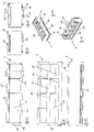
- Fig. 1 shows a system 1 in perspective exploded view.
- the system 1 consists of a base 2 and two carriers 3 arranged one above the other, as well as an upper carrier 4 arranged above the two carriers 3 and a cover 5 arranged on the upper carrier 4.
- each four energy storage 6 are arranged lying.
- Each energy storage 6 consists of a housing 7 with two horizontally oriented side walls 8. Furthermore, in Fig. 1 Connections 9 in the field of energy storage 6 to recognize.
- Fig. 1 can be seen in addition to front covers 10 which are releasably secured in the region of the terminals 9 of the energy storage 6 to the carriers 3 and 4 respectively.
- a system 1 which consists of the base 2, a support 3 and the upper support 4 and the cover 5.
- This is a system 1 which has the minimum number of carriers 3 or upper carrier 4.
- Such a system 1 may have up to eleven carriers 3, wherein a different number of receiving compartments for the energy storage 6, not shown, may be provided.
- the carrier 3 is detailed in the FIGS. 4 to 10 shown.
- Each support 3 is U-shaped in longitudinal section and has a web 11 and two legs 12 arranged at right angles thereto.
- a stiffening element 13 (FIG. Fig. 5 ), which is designed as a profile and the two free ends of the legs 12 connects to each other, wherein the stiffening element 13 is arranged in the upper corner region of the legs 12.
- Fig. 4 shows the bottom view of the carrier 3 and it can be seen that the web 11, as well as the legs 12 at the lower edge portion 14 are double-folded and thus L-shaped, so that an inwardly verspringender edge portion 14 is formed.
- the projection of the edge region 14 is formed in such a way that the surface running parallel to the surface normal of the web 11 or of the legs 12 coincides with a corresponding receptacle on the opposite end of the carrier 3, so that the edge region 14 can be inserted into a further carrier 3, the carriers 3 arranged one above the other are connected to one another such that a relative movement of the adjacently arranged carriers 3 is not possible.
- two additional pressure elements 15 extend over the entire length of the carrier 3 between the mutually facing surfaces of the edge regions 14 of the legs 12.
- the pressure elements 15 are formed as box profiles and welded to the edge regions 14 in the region of the legs 12 ,
- the pressure elements 15 terminate flush with the free edges of the edge regions 14, wherein the flush with the edge regions of the legs 12 surface of the pressure elements 15 form a support surface 16 which is intended to rest on the side walls 8 of the energy storage 6.
- the carrier 3 is divided by the use of plate-shaped separating elements 17 in individual receiving areas for receiving the energy storage 6. Shown are three separating elements 17, so that a total of four receiving areas for the energy storage 6 are formed.
- the separating elements 17 may be connected to the inner surface of the web 11 or guided in guides arranged there. Furthermore, the separating elements 17 with the reinforcing element 13 and the pressure elements 15 are connectable.
- FIGS. 6 to 10 are further constructive embodiments of the carrier 3 can be seen.
- Fig. 6 For example, in the region of the end faces of the legs 12 each have a rectangular opening 18, which serve to receive connecting elements in the form of locking elements 19 on the front cover 10. Both in the web 11, as well as in the legs 12 a plurality of holes 20 are provided for ventilation of the carrier 3 at the area remote from the edge region 14.
- the web 11, as well as the legs 12 are made of a sheet metal element, wherein the free ends of the legs 12 are angled at 90 ° and aligned with each other.
- corner connectors can be provided, which stiffen the respective free end of the legs 12, wherein the corner connectors
- profile elements may be formed in the form of box sections.
- FIGS. 11 to 17 show the upper support 4 in different views.
- the construction of the upper beam 4 is consistent with the construction of the beams 3 disposed below the upper beam 4.
- matching design elements are designated by matching reference numerals.
- the upper support 4 has in addition to the supports 3, a second reinforcing element 21, which is also designed as a box section and parallel to the stiffening element 13, wherein the stiffening element 21 also extends between the two legs 12 and in this case substantially a distance from the stiffening element thirteenth has, which coincides with the distance of the second reinforcing element 21 to the web 11.
- the stiffening element 21 also serves as a pressure element. In the final assembled state, energy storage 6 received by the upper support 4 press from below against the reinforcing element 21 serving as a pressure element. An undesired buckling of the energy store 6 is thus prevented. In this case, only an upper support 4 and not a lower support 3 such a stiffening element 21, because in the final assembled state on an upper support 4, no further support.
- the upper support 4 in the region of the edge portions 14 of the legs 12 and the web 11 has four openings 22, which serve to receive locking elements 23 of the cover 5.
- the locking elements 23 are for example in the Fig. 1 to recognize.
- Fig. 18 the front cover 10 is shown in a perspective view.
- the front cover 10 is formed in a longitudinal section substantially U-shaped and has a web 24 and then two two-angled leg 25, wherein at the free ends of the legs 25, the locking elements 19 are arranged centrally.
- the front cover 10 has an elasticity, which makes it possible to insert the locking elements 19 in the openings 18, wherein the two legs 25 are moved towards each other for this purpose, before the locking elements 19 engage in the opening 18.
- the locking elements 19 are then transferred into a rear grip in the openings 18.
- the locking elements 19 may be formed as a resilient locking tabs.
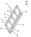
- the base 2 consists of two short profile elements 26 and two long profile elements 27, each extending at right angles to each other and form a frame 28.
- the two long profile elements 27 are connected by stiffening elements 29 extending at equal distances from each other and to the short profile elements 26, wherein the stiffening elements 29 have recesses 30 for receiving an abutment 31 with a contact surface 32 in their upper edge region.
- the abutment 31 is designed as a box profile and terminates substantially flush with the upper surface region of the profile elements 26, 27.
- a projection in the range of a maximum of three millimeters can be provided in order to be able to press the contact surface 32 with high precision on side walls 8 of energy stores 6 which are arranged in the carrier 3, which carrier 3 is placed on the base 2.
- the carrier 3 and the upper carrier 4 form a receiving device 33 for energy storage device 6 to be arranged in the receiving device 33.
- This receiving device 33 is supplemented optionally by the base 2 and the upper cover 5 and the front covers 1.
Landscapes
- Chemical & Material Sciences (AREA)
- Chemical Kinetics & Catalysis (AREA)
- Electrochemistry (AREA)
- General Chemical & Material Sciences (AREA)
- Engineering & Computer Science (AREA)
- Manufacturing & Machinery (AREA)
- Battery Mounting, Suspending (AREA)
Priority Applications (6)
| Application Number | Priority Date | Filing Date | Title |
|---|---|---|---|
| ES17167942T ES2741098T3 (es) | 2017-04-25 | 2017-04-25 | Sistema compuesto de un dispositivo de alojamiento y de acumuladores de energía a disponer en el dispositivo de alojamiento, dispositivo de alojamiento y soportes para el alojamiento de acumuladores de energía |
| PL17167942T PL3396733T3 (pl) | 2017-04-25 | 2017-04-25 | Układ, składający się z urządzenia przyjmującego i zasobników energii, przeznaczonych do umieszczenia w urządzeniu przyjmującym, urządzenie przyjmujące i nośnik do przyjmowania zasobników energii |
| EP17167942.6A EP3396733B1 (de) | 2017-04-25 | 2017-04-25 | System bestehend aus einer aufnahmeeinrichtung und in der aufnahmeeinrichtung anzuordnenden energiespeichern, aufnahmeeinrichtung und träger zur aufnahme von energiespeichern |
| PCT/EP2018/060544 WO2018197536A1 (de) | 2017-04-25 | 2018-04-25 | System bestehend aus einer aufnahmeeinrichtung und in der aufnahmeeinrichtung anzuordnenden energiespeichern |
| CN201880027717.1A CN110603660B (zh) | 2017-04-25 | 2018-04-25 | 包括保持器和可以放置在该保持器中的储能源的系统 |
| US16/607,261 US11258127B2 (en) | 2017-04-25 | 2018-04-25 | System comprising of a holder and stored energy sources which can be placed in the holder |
Applications Claiming Priority (1)
| Application Number | Priority Date | Filing Date | Title |
|---|---|---|---|
| EP17167942.6A EP3396733B1 (de) | 2017-04-25 | 2017-04-25 | System bestehend aus einer aufnahmeeinrichtung und in der aufnahmeeinrichtung anzuordnenden energiespeichern, aufnahmeeinrichtung und träger zur aufnahme von energiespeichern |
Publications (2)
| Publication Number | Publication Date |
|---|---|
| EP3396733A1 EP3396733A1 (de) | 2018-10-31 |
| EP3396733B1 true EP3396733B1 (de) | 2019-06-19 |
Family
ID=58632280
Family Applications (1)
| Application Number | Title | Priority Date | Filing Date |
|---|---|---|---|
| EP17167942.6A Active EP3396733B1 (de) | 2017-04-25 | 2017-04-25 | System bestehend aus einer aufnahmeeinrichtung und in der aufnahmeeinrichtung anzuordnenden energiespeichern, aufnahmeeinrichtung und träger zur aufnahme von energiespeichern |
Country Status (6)
| Country | Link |
|---|---|
| US (1) | US11258127B2 (pl) |
| EP (1) | EP3396733B1 (pl) |
| CN (1) | CN110603660B (pl) |
| ES (1) | ES2741098T3 (pl) |
| PL (1) | PL3396733T3 (pl) |
| WO (1) | WO2018197536A1 (pl) |
Families Citing this family (10)
| Publication number | Priority date | Publication date | Assignee | Title |
|---|---|---|---|---|
| US20200044298A1 (en) * | 2018-08-06 | 2020-02-06 | Ford Global Technologies, Llc | Battery for electrified vehicle and corresponding method of accommodating for variable cell thickness |
| CN110190204A (zh) * | 2019-05-15 | 2019-08-30 | 佛山赛能新能源有限公司 | 一种耐高温阀控式铅酸蓄电池及其正极板的制作方法 |
| DE202019105570U1 (de) | 2019-10-09 | 2019-10-28 | Hoppecke Batterien Gmbh & Co. Kg | Batterieschrank, Schranksystem und System |
| DE102020203873A1 (de) * | 2020-03-25 | 2021-09-30 | Elringklinger Ag | Batteriemodule, Batterievorrichtungen und Verfahren zum Herstellen eines Batteriemoduls |
| EP4156368A1 (de) | 2021-09-24 | 2023-03-29 | HOPPECKE Batterien GmbH & Co. KG. | System bestehend aus einer stapelhilfe und einer mehrzahl von agm-batterien |
| DE102022123511A1 (de) | 2022-09-14 | 2024-03-14 | Hoppecke Batterien Gmbh & Co. Kg | System bestehend aus einer Stapelhilfe und einer Mehrzahl von AGM-Batterien |
| DE102022123512A1 (de) | 2022-09-14 | 2024-03-14 | Hoppecke Batterien Gmbh & Co. Kg | Batterie, insbesondere AGM-Batterie sowie System bestehend aus einer Stapelhilfe und einer Mehrzahl von AGM-Batterien |
| DE102022123510A1 (de) | 2022-09-14 | 2024-03-14 | Hoppecke Batterien Gmbh & Co. Kg | System bestehend aus einer Stapelhilfe und einer Mehrzahl von AGM-Batterien |
| EP4340109B1 (de) | 2022-09-14 | 2025-10-01 | HOPPECKE Batterien GmbH & Co. KG. | System bestehend aus einer stapelhilfe und einer mehrzahl von agm-batterien |
| DE102022123509A1 (de) | 2022-09-14 | 2024-03-14 | Hoppecke Batterien Gmbh & Co. Kg | System bestehend aus einer Stapelhilfe und einer Mehrzahl von AGM-Batterien |
Family Cites Families (9)
| Publication number | Priority date | Publication date | Assignee | Title |
|---|---|---|---|---|
| US4425412A (en) * | 1982-05-26 | 1984-01-10 | Eagle-Picher Industries, Inc. | Lead/acid battery having horizontal plates |
| US5366827A (en) * | 1992-06-10 | 1994-11-22 | Digital Equipment Corporation | Modular housing for batteries and battery charger |
| US5304434A (en) * | 1992-06-15 | 1994-04-19 | Gnb Industrial Battery Co. | Modular cabinet for large-sized sealed lead-acid cells |
| EP0575060B1 (en) * | 1992-06-15 | 1996-09-11 | Gnb Industrial Battery Company | Modular battery cabinet assembly |
| US5981101A (en) * | 1997-06-02 | 1999-11-09 | Gnb Technologies, Inc. | Modular cell tray assembly for sealed lead-acid cells |
| US6641951B1 (en) * | 1998-09-21 | 2003-11-04 | Douglas Battery Manufacturing Company | Battery cell tray assembly and sytem |
| DE202007012635U1 (de) | 2007-09-08 | 2007-11-29 | Hoppecke Batterien Gmbh & Co. Kg | Gehäuse für ein Energieversorgungssystem |
| EP2690748B1 (en) * | 2011-05-31 | 2018-09-12 | LG Chem, Ltd. | Power storage device, power storage system using same, and method for configuring power storage system |
| CN106207036B (zh) * | 2016-08-29 | 2019-04-09 | 北京普莱德新能源电池科技有限公司 | 一种层叠式动力电池包箱体 |
-
2017
- 2017-04-25 EP EP17167942.6A patent/EP3396733B1/de active Active
- 2017-04-25 PL PL17167942T patent/PL3396733T3/pl unknown
- 2017-04-25 ES ES17167942T patent/ES2741098T3/es active Active
-
2018
- 2018-04-25 WO PCT/EP2018/060544 patent/WO2018197536A1/de not_active Ceased
- 2018-04-25 CN CN201880027717.1A patent/CN110603660B/zh not_active Expired - Fee Related
- 2018-04-25 US US16/607,261 patent/US11258127B2/en active Active
Non-Patent Citations (1)
| Title |
|---|
| None * |
Also Published As
| Publication number | Publication date |
|---|---|
| US20200303696A1 (en) | 2020-09-24 |
| WO2018197536A1 (de) | 2018-11-01 |
| CN110603660A (zh) | 2019-12-20 |
| CN110603660B (zh) | 2022-05-27 |
| PL3396733T3 (pl) | 2019-11-29 |
| ES2741098T3 (es) | 2020-02-10 |
| EP3396733A1 (de) | 2018-10-31 |
| US11258127B2 (en) | 2022-02-22 |
Similar Documents
| Publication | Publication Date | Title |
|---|---|---|
| EP3396733A1 (de) | System bestehend aus einer aufnahmeeinrichtung und in der aufnahmeeinrichtung anzuordnenden energiespeichern, aufnahmeeinrichtung und träger zur aufnahme von energiespeichern | |
| DE202019105570U1 (de) | Batterieschrank, Schranksystem und System | |
| DE4319653A1 (de) | Schrank in Modulbauweise für große vergossene Bleiakkumulatorzellen | |
| DE4319654A1 (de) | Batterieschrankanordnung in Modulbauweise | |
| DE102010013024A1 (de) | Batterie aus einer Vielzahl von Batterieeinzelzellen | |
| DE102010031462A1 (de) | Batteriezellenmodul, Batterie und Kraftfahrzeug | |
| DE102022118386A1 (de) | System bestehend aus einer Stapelhilfe und einer Mehrzahl von AGM-Batterien | |
| DE112018002974T5 (de) | Energiespeichervorrichtung | |
| EP3218946A1 (de) | Aufnahme für ein batteriemodul und batteriemodul aufweisend eine derartige aufnahme | |
| DE102018123691B4 (de) | Gehäuse | |
| DE202021004396U1 (de) | Batteriemodul und Batteriepack mit diesem Modul | |
| DE102017005400A1 (de) | Energiespeicheranordnung und Kraftfahrzeug | |
| DE202012104578U1 (de) | Modulares Batteriegestell | |
| EP3061143B1 (de) | Gitteranordnung für eine plattenförmige batterieelektrode und akkumulator | |
| EP2856535B1 (de) | Speicherelement umfassend mehrere lithium-zellen | |
| WO2022184761A1 (de) | Batterie mit einem wässrigem, alkalihaltigem elektrolyten | |
| EP4340110B1 (de) | System bestehend aus einer stapelhilfe und einer mehrzahl von agm-batterien | |
| DE102008043960A1 (de) | Vorrichtung mit mindestens einer Akkumulatorzelle | |
| EP4340109B1 (de) | System bestehend aus einer stapelhilfe und einer mehrzahl von agm-batterien | |
| DE102022202055B3 (de) | Batteriezelle | |
| DE102013015783A1 (de) | Batterie | |
| DE102022123512A1 (de) | Batterie, insbesondere AGM-Batterie sowie System bestehend aus einer Stapelhilfe und einer Mehrzahl von AGM-Batterien | |
| DE102024105942A1 (de) | Oberträger-entwurf für eine zylindrische batteriezellenanordnung | |
| WO2025002565A1 (de) | System mit einer stapelhilfe und einer mehrzahl von batterien | |
| EP4340104A1 (de) | System bestehend aus einer stapelhilfe und einer mehrzahl von agm-batterien |
Legal Events
| Date | Code | Title | Description |
|---|---|---|---|
| STAA | Information on the status of an ep patent application or granted ep patent |
Free format text: STATUS: EXAMINATION IS IN PROGRESS |
|
| PUAI | Public reference made under article 153(3) epc to a published international application that has entered the european phase |
Free format text: ORIGINAL CODE: 0009012 |
|
| 17P | Request for examination filed |
Effective date: 20180424 |
|
| AK | Designated contracting states |
Kind code of ref document: A1 Designated state(s): AL AT BE BG CH CY CZ DE DK EE ES FI FR GB GR HR HU IE IS IT LI LT LU LV MC MK MT NL NO PL PT RO RS SE SI SK SM TR |
|
| AX | Request for extension of the european patent |
Extension state: BA ME |
|
| REG | Reference to a national code |
Ref country code: DE Ref legal event code: R079 Ref document number: 502017001563 Country of ref document: DE Free format text: PREVIOUS MAIN CLASS: H01M0002100000 Ipc: H01M0002020000 |
|
| RIC1 | Information provided on ipc code assigned before grant |
Ipc: H01M 2/02 20060101AFI20181218BHEP |
|
| GRAP | Despatch of communication of intention to grant a patent |
Free format text: ORIGINAL CODE: EPIDOSNIGR1 |
|
| STAA | Information on the status of an ep patent application or granted ep patent |
Free format text: STATUS: GRANT OF PATENT IS INTENDED |
|
| INTG | Intention to grant announced |
Effective date: 20190208 |
|
| GRAS | Grant fee paid |
Free format text: ORIGINAL CODE: EPIDOSNIGR3 |
|
| GRAA | (expected) grant |
Free format text: ORIGINAL CODE: 0009210 |
|
| STAA | Information on the status of an ep patent application or granted ep patent |
Free format text: STATUS: THE PATENT HAS BEEN GRANTED |
|
| AK | Designated contracting states |
Kind code of ref document: B1 Designated state(s): AL AT BE BG CH CY CZ DE DK EE ES FI FR GB GR HR HU IE IS IT LI LT LU LV MC MK MT NL NO PL PT RO RS SE SI SK SM TR |
|
| REG | Reference to a national code |
Ref country code: GB Ref legal event code: FG4D Free format text: NOT ENGLISH |
|
| REG | Reference to a national code |
Ref country code: CH Ref legal event code: EP |
|
| REG | Reference to a national code |
Ref country code: IE Ref legal event code: FG4D Free format text: LANGUAGE OF EP DOCUMENT: GERMAN |
|
| REG | Reference to a national code |
Ref country code: DE Ref legal event code: R096 Ref document number: 502017001563 Country of ref document: DE |
|
| REG | Reference to a national code |
Ref country code: AT Ref legal event code: REF Ref document number: 1146635 Country of ref document: AT Kind code of ref document: T Effective date: 20190715 |
|
| REG | Reference to a national code |
Ref country code: CH Ref legal event code: NV Representative=s name: E. BLUM AND CO. AG PATENT- UND MARKENANWAELTE , CH |
|
| REG | Reference to a national code |
Ref country code: NL Ref legal event code: FP |
|
| PG25 | Lapsed in a contracting state [announced via postgrant information from national office to epo] |
Ref country code: LT Free format text: LAPSE BECAUSE OF FAILURE TO SUBMIT A TRANSLATION OF THE DESCRIPTION OR TO PAY THE FEE WITHIN THE PRESCRIBED TIME-LIMIT Effective date: 20190619 Ref country code: FI Free format text: LAPSE BECAUSE OF FAILURE TO SUBMIT A TRANSLATION OF THE DESCRIPTION OR TO PAY THE FEE WITHIN THE PRESCRIBED TIME-LIMIT Effective date: 20190619 Ref country code: NO Free format text: LAPSE BECAUSE OF FAILURE TO SUBMIT A TRANSLATION OF THE DESCRIPTION OR TO PAY THE FEE WITHIN THE PRESCRIBED TIME-LIMIT Effective date: 20190919 Ref country code: HR Free format text: LAPSE BECAUSE OF FAILURE TO SUBMIT A TRANSLATION OF THE DESCRIPTION OR TO PAY THE FEE WITHIN THE PRESCRIBED TIME-LIMIT Effective date: 20190619 Ref country code: AL Free format text: LAPSE BECAUSE OF FAILURE TO SUBMIT A TRANSLATION OF THE DESCRIPTION OR TO PAY THE FEE WITHIN THE PRESCRIBED TIME-LIMIT Effective date: 20190619 Ref country code: SE Free format text: LAPSE BECAUSE OF FAILURE TO SUBMIT A TRANSLATION OF THE DESCRIPTION OR TO PAY THE FEE WITHIN THE PRESCRIBED TIME-LIMIT Effective date: 20190619 |
|
| REG | Reference to a national code |
Ref country code: LT Ref legal event code: MG4D |
|
| PG25 | Lapsed in a contracting state [announced via postgrant information from national office to epo] |
Ref country code: RS Free format text: LAPSE BECAUSE OF FAILURE TO SUBMIT A TRANSLATION OF THE DESCRIPTION OR TO PAY THE FEE WITHIN THE PRESCRIBED TIME-LIMIT Effective date: 20190619 Ref country code: LV Free format text: LAPSE BECAUSE OF FAILURE TO SUBMIT A TRANSLATION OF THE DESCRIPTION OR TO PAY THE FEE WITHIN THE PRESCRIBED TIME-LIMIT Effective date: 20190619 Ref country code: BG Free format text: LAPSE BECAUSE OF FAILURE TO SUBMIT A TRANSLATION OF THE DESCRIPTION OR TO PAY THE FEE WITHIN THE PRESCRIBED TIME-LIMIT Effective date: 20190919 Ref country code: GR Free format text: LAPSE BECAUSE OF FAILURE TO SUBMIT A TRANSLATION OF THE DESCRIPTION OR TO PAY THE FEE WITHIN THE PRESCRIBED TIME-LIMIT Effective date: 20190920 |
|
| PG25 | Lapsed in a contracting state [announced via postgrant information from national office to epo] |
Ref country code: RO Free format text: LAPSE BECAUSE OF FAILURE TO SUBMIT A TRANSLATION OF THE DESCRIPTION OR TO PAY THE FEE WITHIN THE PRESCRIBED TIME-LIMIT Effective date: 20190619 Ref country code: CZ Free format text: LAPSE BECAUSE OF FAILURE TO SUBMIT A TRANSLATION OF THE DESCRIPTION OR TO PAY THE FEE WITHIN THE PRESCRIBED TIME-LIMIT Effective date: 20190619 Ref country code: SK Free format text: LAPSE BECAUSE OF FAILURE TO SUBMIT A TRANSLATION OF THE DESCRIPTION OR TO PAY THE FEE WITHIN THE PRESCRIBED TIME-LIMIT Effective date: 20190619 Ref country code: EE Free format text: LAPSE BECAUSE OF FAILURE TO SUBMIT A TRANSLATION OF THE DESCRIPTION OR TO PAY THE FEE WITHIN THE PRESCRIBED TIME-LIMIT Effective date: 20190619 Ref country code: PT Free format text: LAPSE BECAUSE OF FAILURE TO SUBMIT A TRANSLATION OF THE DESCRIPTION OR TO PAY THE FEE WITHIN THE PRESCRIBED TIME-LIMIT Effective date: 20191021 |
|
| REG | Reference to a national code |
Ref country code: ES Ref legal event code: FG2A Ref document number: 2741098 Country of ref document: ES Kind code of ref document: T3 Effective date: 20200210 |
|
| PG25 | Lapsed in a contracting state [announced via postgrant information from national office to epo] |
Ref country code: IS Free format text: LAPSE BECAUSE OF FAILURE TO SUBMIT A TRANSLATION OF THE DESCRIPTION OR TO PAY THE FEE WITHIN THE PRESCRIBED TIME-LIMIT Effective date: 20191019 Ref country code: SM Free format text: LAPSE BECAUSE OF FAILURE TO SUBMIT A TRANSLATION OF THE DESCRIPTION OR TO PAY THE FEE WITHIN THE PRESCRIBED TIME-LIMIT Effective date: 20190619 Ref country code: IT Free format text: LAPSE BECAUSE OF FAILURE TO SUBMIT A TRANSLATION OF THE DESCRIPTION OR TO PAY THE FEE WITHIN THE PRESCRIBED TIME-LIMIT Effective date: 20190619 |
|
| PG25 | Lapsed in a contracting state [announced via postgrant information from national office to epo] |
Ref country code: TR Free format text: LAPSE BECAUSE OF FAILURE TO SUBMIT A TRANSLATION OF THE DESCRIPTION OR TO PAY THE FEE WITHIN THE PRESCRIBED TIME-LIMIT Effective date: 20190619 |
|
| PG25 | Lapsed in a contracting state [announced via postgrant information from national office to epo] |
Ref country code: DK Free format text: LAPSE BECAUSE OF FAILURE TO SUBMIT A TRANSLATION OF THE DESCRIPTION OR TO PAY THE FEE WITHIN THE PRESCRIBED TIME-LIMIT Effective date: 20190619 |
|
| PG25 | Lapsed in a contracting state [announced via postgrant information from national office to epo] |
Ref country code: IS Free format text: LAPSE BECAUSE OF FAILURE TO SUBMIT A TRANSLATION OF THE DESCRIPTION OR TO PAY THE FEE WITHIN THE PRESCRIBED TIME-LIMIT Effective date: 20200224 |
|
| REG | Reference to a national code |
Ref country code: DE Ref legal event code: R097 Ref document number: 502017001563 Country of ref document: DE |
|
| REG | Reference to a national code |
Ref country code: DE Ref legal event code: R084 Ref document number: 502017001563 Country of ref document: DE |
|
| PLBE | No opposition filed within time limit |
Free format text: ORIGINAL CODE: 0009261 |
|
| STAA | Information on the status of an ep patent application or granted ep patent |
Free format text: STATUS: NO OPPOSITION FILED WITHIN TIME LIMIT |
|
| PG2D | Information on lapse in contracting state deleted |
Ref country code: IS |
|
| 26N | No opposition filed |
Effective date: 20200603 |
|
| REG | Reference to a national code |
Ref country code: DE Ref legal event code: R079 Ref document number: 502017001563 Country of ref document: DE Free format text: PREVIOUS MAIN CLASS: H01M0002020000 Ipc: H01M0050100000 |
|
| PG25 | Lapsed in a contracting state [announced via postgrant information from national office to epo] |
Ref country code: MC Free format text: LAPSE BECAUSE OF FAILURE TO SUBMIT A TRANSLATION OF THE DESCRIPTION OR TO PAY THE FEE WITHIN THE PRESCRIBED TIME-LIMIT Effective date: 20190619 |
|
| PG25 | Lapsed in a contracting state [announced via postgrant information from national office to epo] |
Ref country code: LU Free format text: LAPSE BECAUSE OF NON-PAYMENT OF DUE FEES Effective date: 20200425 |
|
| PG25 | Lapsed in a contracting state [announced via postgrant information from national office to epo] |
Ref country code: IE Free format text: LAPSE BECAUSE OF NON-PAYMENT OF DUE FEES Effective date: 20200425 |
|
| PGFP | Annual fee paid to national office [announced via postgrant information from national office to epo] |
Ref country code: FR Payment date: 20210423 Year of fee payment: 5 |
|
| PGFP | Annual fee paid to national office [announced via postgrant information from national office to epo] |
Ref country code: GB Payment date: 20210422 Year of fee payment: 5 Ref country code: PL Payment date: 20210416 Year of fee payment: 5 Ref country code: ES Payment date: 20210621 Year of fee payment: 5 Ref country code: BE Payment date: 20210420 Year of fee payment: 5 Ref country code: CH Payment date: 20210420 Year of fee payment: 5 |
|
| PGFP | Annual fee paid to national office [announced via postgrant information from national office to epo] |
Ref country code: NL Payment date: 20210420 Year of fee payment: 5 |
|
| PG25 | Lapsed in a contracting state [announced via postgrant information from national office to epo] |
Ref country code: MT Free format text: LAPSE BECAUSE OF FAILURE TO SUBMIT A TRANSLATION OF THE DESCRIPTION OR TO PAY THE FEE WITHIN THE PRESCRIBED TIME-LIMIT Effective date: 20190619 Ref country code: CY Free format text: LAPSE BECAUSE OF FAILURE TO SUBMIT A TRANSLATION OF THE DESCRIPTION OR TO PAY THE FEE WITHIN THE PRESCRIBED TIME-LIMIT Effective date: 20190619 |
|
| PG25 | Lapsed in a contracting state [announced via postgrant information from national office to epo] |
Ref country code: MK Free format text: LAPSE BECAUSE OF FAILURE TO SUBMIT A TRANSLATION OF THE DESCRIPTION OR TO PAY THE FEE WITHIN THE PRESCRIBED TIME-LIMIT Effective date: 20190619 |
|
| PGFP | Annual fee paid to national office [announced via postgrant information from national office to epo] |
Ref country code: DE Payment date: 20220628 Year of fee payment: 6 |
|
| REG | Reference to a national code |
Ref country code: CH Ref legal event code: PL |
|
| REG | Reference to a national code |
Ref country code: NL Ref legal event code: MM Effective date: 20220501 |
|
| GBPC | Gb: european patent ceased through non-payment of renewal fee |
Effective date: 20220425 |
|
| REG | Reference to a national code |
Ref country code: BE Ref legal event code: MM Effective date: 20220430 |
|
| PG25 | Lapsed in a contracting state [announced via postgrant information from national office to epo] |
Ref country code: NL Free format text: LAPSE BECAUSE OF NON-PAYMENT OF DUE FEES Effective date: 20220501 Ref country code: LI Free format text: LAPSE BECAUSE OF NON-PAYMENT OF DUE FEES Effective date: 20220430 Ref country code: GB Free format text: LAPSE BECAUSE OF NON-PAYMENT OF DUE FEES Effective date: 20220425 Ref country code: FR Free format text: LAPSE BECAUSE OF NON-PAYMENT OF DUE FEES Effective date: 20220430 Ref country code: CH Free format text: LAPSE BECAUSE OF NON-PAYMENT OF DUE FEES Effective date: 20220430 |
|
| PG25 | Lapsed in a contracting state [announced via postgrant information from national office to epo] |
Ref country code: BE Free format text: LAPSE BECAUSE OF NON-PAYMENT OF DUE FEES Effective date: 20220430 |
|
| REG | Reference to a national code |
Ref country code: ES Ref legal event code: FD2A Effective date: 20230529 |
|
| PG25 | Lapsed in a contracting state [announced via postgrant information from national office to epo] |
Ref country code: PL Free format text: LAPSE BECAUSE OF NON-PAYMENT OF DUE FEES Effective date: 20220425 |
|
| REG | Reference to a national code |
Ref country code: AT Ref legal event code: MM01 Ref document number: 1146635 Country of ref document: AT Kind code of ref document: T Effective date: 20220425 |
|
| P01 | Opt-out of the competence of the unified patent court (upc) registered |
Effective date: 20230523 |
|
| PG25 | Lapsed in a contracting state [announced via postgrant information from national office to epo] |
Ref country code: ES Free format text: LAPSE BECAUSE OF NON-PAYMENT OF DUE FEES Effective date: 20220426 Ref country code: AT Free format text: LAPSE BECAUSE OF NON-PAYMENT OF DUE FEES Effective date: 20220425 |
|
| PG25 | Lapsed in a contracting state [announced via postgrant information from national office to epo] |
Ref country code: SI Free format text: LAPSE BECAUSE OF FAILURE TO SUBMIT A TRANSLATION OF THE DESCRIPTION OR TO PAY THE FEE WITHIN THE PRESCRIBED TIME-LIMIT Effective date: 20190619 |
|
| REG | Reference to a national code |
Ref country code: DE Ref legal event code: R119 Ref document number: 502017001563 Country of ref document: DE |
|
| PG25 | Lapsed in a contracting state [announced via postgrant information from national office to epo] |
Ref country code: DE Free format text: LAPSE BECAUSE OF NON-PAYMENT OF DUE FEES Effective date: 20231103 |