EP3396687B1 - Antriebsverfahren eines transformators und verbindungsanordnung für transformator - Google Patents
Antriebsverfahren eines transformators und verbindungsanordnung für transformator Download PDFInfo
- Publication number
- EP3396687B1 EP3396687B1 EP17168735.3A EP17168735A EP3396687B1 EP 3396687 B1 EP3396687 B1 EP 3396687B1 EP 17168735 A EP17168735 A EP 17168735A EP 3396687 B1 EP3396687 B1 EP 3396687B1
- Authority
- EP
- European Patent Office
- Prior art keywords
- coils
- groups
- transformer
- supply voltage
- entirety
- Prior art date
- Legal status (The legal status is an assumption and is not a legal conclusion. Google has not performed a legal analysis and makes no representation as to the accuracy of the status listed.)
- Active
Links
Images
Classifications
-
- H—ELECTRICITY
- H01—ELECTRIC ELEMENTS
- H01F—MAGNETS; INDUCTANCES; TRANSFORMERS; SELECTION OF MATERIALS FOR THEIR MAGNETIC PROPERTIES
- H01F27/00—Details of transformers or inductances, in general
- H01F27/42—Circuits specially adapted for the purpose of modifying, or compensating for, electric characteristics of transformers, reactors, or choke coils
-
- H—ELECTRICITY
- H01—ELECTRIC ELEMENTS
- H01F—MAGNETS; INDUCTANCES; TRANSFORMERS; SELECTION OF MATERIALS FOR THEIR MAGNETIC PROPERTIES
- H01F27/00—Details of transformers or inductances, in general
- H01F27/34—Special means for preventing or reducing unwanted electric or magnetic effects, e.g. no-load losses, reactive currents, harmonics, oscillations, leakage fields
-
- H—ELECTRICITY
- H01—ELECTRIC ELEMENTS
- H01F—MAGNETS; INDUCTANCES; TRANSFORMERS; SELECTION OF MATERIALS FOR THEIR MAGNETIC PROPERTIES
- H01F29/00—Variable transformers or inductances not covered by group H01F21/00
- H01F29/02—Variable transformers or inductances not covered by group H01F21/00 with tappings on coil or winding; with provision for rearrangement or interconnection of windings
-
- H—ELECTRICITY
- H02—GENERATION; CONVERSION OR DISTRIBUTION OF ELECTRIC POWER
- H02M—APPARATUS FOR CONVERSION BETWEEN AC AND AC, BETWEEN AC AND DC, OR BETWEEN DC AND DC, AND FOR USE WITH MAINS OR SIMILAR POWER SUPPLY SYSTEMS; CONVERSION OF DC OR AC INPUT POWER INTO SURGE OUTPUT POWER; CONTROL OR REGULATION THEREOF
- H02M5/00—Conversion of AC power input into AC power output, e.g. for change of voltage, for change of frequency, for change of number of phases
- H02M5/02—Conversion of AC power input into AC power output, e.g. for change of voltage, for change of frequency, for change of number of phases without intermediate conversion into DC
- H02M5/04—Conversion of AC power input into AC power output, e.g. for change of voltage, for change of frequency, for change of number of phases without intermediate conversion into DC by static converters
- H02M5/10—Conversion of AC power input into AC power output, e.g. for change of voltage, for change of frequency, for change of number of phases without intermediate conversion into DC by static converters using transformers
-
- H—ELECTRICITY
- H02—GENERATION; CONVERSION OR DISTRIBUTION OF ELECTRIC POWER
- H02M—APPARATUS FOR CONVERSION BETWEEN AC AND AC, BETWEEN AC AND DC, OR BETWEEN DC AND DC, AND FOR USE WITH MAINS OR SIMILAR POWER SUPPLY SYSTEMS; CONVERSION OF DC OR AC INPUT POWER INTO SURGE OUTPUT POWER; CONTROL OR REGULATION THEREOF
- H02M1/00—Details of apparatus for conversion
- H02M1/32—Means for protecting converters other than automatic disconnection
-
- H—ELECTRICITY
- H02—GENERATION; CONVERSION OR DISTRIBUTION OF ELECTRIC POWER
- H02M—APPARATUS FOR CONVERSION BETWEEN AC AND AC, BETWEEN AC AND DC, OR BETWEEN DC AND DC, AND FOR USE WITH MAINS OR SIMILAR POWER SUPPLY SYSTEMS; CONVERSION OF DC OR AC INPUT POWER INTO SURGE OUTPUT POWER; CONTROL OR REGULATION THEREOF
- H02M1/00—Details of apparatus for conversion
- H02M1/36—Means for starting or stopping converters
Definitions
- aspects of the present disclosure relate generally to an energizing method of a transformer, and to a transformer connection assembly having an energizing controller configured to perform an energizing method.
- a transient high inrush current flows upon connection of the transformer to a supply voltage when the transformer is in an unenergized, or unmagnetized, state.
- the high inrush current flows as a result from a magnetic saturation in the transformer core.
- the core is sufficiently magnetized, and the current flowing into the primary side during the regular operation is usually not nearly as high as a possible inrush current.
- Supply systems upstream of the point of connection of the supply voltage to the primary side of the transformer may comprise protection installations for limiting a current which exceeds a certain value.
- protection installations can disconnect the supply voltage immediately in the case that the inrush current is too high. Due to the transient nature of the inrush current, also a DC component is induced on the supply side of the installation, which can make some protection installations to operate, i. e. to disrupt the connection.
- Conventional methods and installations for limiting an inrush current of a transformer include an introduction of an air gap into the magnetic core, synchronizing the time of connection to a phase of the supply voltage, and/or a pre-energization by auxiliary circuits.
- An object of the invention is to provide a simplified energizing method for a transformer and/or to provide a simplified transformer connection assembly, each being cost-efficient and reliably suppressing an inrush current to an allowable amount.
- an energizing method according to claim 1, and a transformer connection assembly according to claim 10 are provided.
- an energizing method of a transformer comprises at least two groups of coils forming primary transformer windings, all of coils that form the at least two groups of coils being connected or connectible in parallel to each other, and at least one secondary transformer winding.
- the windings are typically arranged on a common transformer core, e.g. made of a ferromagnetic material such as iron, in order to magnetically couple the primary transformer windings to the at least one secondary transformer winding.
- the transformer core is a gapless core, i. e. a core in which no functional air gap for intendedly enhancing the reluctance in the magnetic circuit of the transformer, is provided.
- first a supply voltage is supplied to a first number of the groups of coils for a predetermined amount of time.
- the first number of coils is less than the entirety of groups of coils.
- the first number may be selected according to an equivalent impedance of the first number of groups of coils, such that when supplying the supply voltage having a predetermined amplitude to the first number of the groups of coils in a substantially unenergized (unmagnetized) state, a predetermined inrush AC current is not exceeded and/or DC component requirements are met.
- the predetermined amplitude of the supply voltage is optionally a root mean square amplitude of a single-phase AC electric supply voltage.
- the predetermined inrush current is typically selected such that a rated current or a specificied maximum transient current of primary-side electrical components is not exceeded, and/or or DC component requirements are met.
- primary-side electrical components include, but are not limited to, protection devices arranged to interrupt an excessive current flowing into the primary side of the transformer.
- the predetermined amount of time for supplying the supply voltage to the first number of the groups of coils is selected such that a sufficient magnetic energization (i.e. a sufficient magnetization) of the groups of coils forming the primary transformer windings can be reasonably assumed.
- a sufficient magnetic energization may be assumed, for example, when in a given transformer, the common magnetic flux, which is caused by supplying the supply voltage to the first number of the groups of coils, has reached at least 50% or at least 60% or at least 70% of a magnetic flux during the nominal operation of the transformer.
- a sufficient magnetic energization may be assumed, for example, when in a given transformer the current that flows into the first number of groups of coils has substantially reached a steady state.
- the exemplary conditions for a sufficient magnetic energization are merely examples, and that neither of the technical quantities taken as an example (e. g. the amount of the common magnetic flux, the current flowing into the first number of groups of coils) needs to be actually measured.
- the conditions may be pre-calculated, and a reasonable value may be specified for the predetermined amount of time of supplying the first voltage to the first number of the groups of coils.
- a non-limiting example for the predetermined amount of time of supplying the first voltage to the first number of the groups of coils, when using the method in energizing a typical traction transformer of an AC electric train, is, for example, more than 0.04 seconds and less than 5 seconds.
- the predetermined amount of time may however be in a range of up to 30 seconds, for example.
- supplying the supply voltage to the first number of the groups of coils involves switching a voltage from a voltage terminal to the first number of coils. Additionally, supplying the supply voltage to the entirety of the groups of coils involves switching a voltage from a voltage terminal to the entirety of the groups of coils. Switching the supply voltage from the voltage terminal for performing the method involves a controlled operation.
- a transition from supplying the supply voltage to less than the entirety of the groups of coils for a predetermined amount of time to supplying the supply voltage to the entirety of the groups of coils is performed in an unsynchronized manner with respect to the phase of the supply voltage.
- a phase of the supply need not be taken care of when transitioning from one stage of the method to the other, e. g. when switching the voltage from the voltage terminal to the entirety of the groups of coils after the predetermined amount of time has passed. Without any complex phase synchronization, the inrush current in the first stage of the method is reliably limited, and no further inrush current will be produced in the subsequent stage of the method.
- the groups of coils each have the same number of coil windings. This allows for a particularly simple configuration, while yet suppressing the inrush current in a reliable manner. It is however noted, that according to other aspects of the invention, the groups of coils may have different numbers of coil windings.
- a ratio of the first number of groups of coils to the entirety (i.e. entire number) of groups of coils is less than 1, optionally less than 1/12 or 1/16 or less than 1/16.
- the inrush current may be limited to a particularly low value; yet, due to the common magnetic flux caused in the first stage of the method, a further inrush current occurring when transitioning to the nominal operation of the transformer is suppressed.
- a transformer connection assembly comprises a transformer having at least two groups of coils forming primary transformer windings, all of coils that form the at least two groups (5a, 5b) of coils being connected or connectible in parallel to each other, and at least one secondary transformer winding.
- the groups of coils are arranged on the transformer such that in an operational state of the transformer, the groups of coils are passed through by a common magnetic flux.
- the transformer connection assembly further comprises a first switch, wherein in a closed state of the first switch, a supply voltage terminal is connected to a first number of the groups of coils, the first number being less than the entirety or entire number of groups of coils.
- the transformer connection assembly further comprises a second switch, wherein in a closed state of the second switch, the supply voltage terminal is connected to the entirety of the groups of coils. Furthermore, the transformer connection assembly comprises an energizing controller.
- the energizing controller is configured to perform an energizing method as described herein.
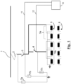
- FIG. 1 is a schematic view of a transformer connection assembly for illustrating an embodiment.
- a transformer comprises a primary transformer winding 5 on the primary side of the transformer and a secondary transformer winding 6 on the secondary side of the transformer.
- the secondary transformer winding 6 comprises multiple coils, but is not limited thereto.
- the primary transformer winding 5 has at least two groups 5a, 5b of coils which, in their entirety, form the primary transformer winding.
- the transformer may, for example, be a traction transformer used in an AC electric train.
- the traction transformer may be suited to accommodate different primary-side voltages (supply voltages) and different primary-side frequencies, such as voltages of up to 25 kV and having frequencies of 16.7 Hz up to 50 Hz, for example.
- the primary side of the transformer is connectible to a catenary 1 via a pantograph 2.
- the pantograph 2 in Fig. 1 serves as a supply voltage terminal for supplying a supply voltage to the primary side of the transformer.
- a first switch 3 and a second switch 4 are provided.
- the first switch 3 may typically be a main circuit breaker 3, and the second switch 4 may be an auxiliary switching device 4.
- the first and second switches 3, 4 have a rated voltage corresponding to or exceeding the voltage at the supply voltage terminal, e. g. a rated voltage of 15 kV or a rated voltage of 25 kV.
- surge arresters 7a, 7b, 7c are installed.
- the surge arresters 7a, 7b, 7c help to avoid unwanted resonance effects and/or local over-voltages.
Landscapes
- Engineering & Computer Science (AREA)
- Power Engineering (AREA)
- Ac-Ac Conversion (AREA)
- Protection Of Transformers (AREA)
Claims (13)
- Bestromungsverfahren eines Transformators, wobei der Transformator mindestens zwei Gruppen (5a, 5b) von Spulen, die primäre Transformatorwicklungen (5) bilden, wobei alle Spulen, die die mindestens zwei Gruppen (5a, 5b) von Spulen bilden, parallel zueinander verbunden oder verbindbar sind, und mindestens eine sekundäre Transformatorwicklung (6) umfasst, wobei das Verfahren in der angegebenen Reihenfolge Folgendes umfasst:a. Zuführen einer Versorgungsspannung an eine erste Anzahl (5a) der Gruppen (5a, 5b) von Spulen für eine vorbestimmte Zeitdauer, wobei die erste Anzahl (5a) kleiner als die Gesamtheit von Gruppen (5a, 5b) von Spulen ist, wodurch ein gemeinsamer magnetischer Fluss durch die Gruppen (5a, 5b) von Spulen geleitet wird; undb. Zuführen der Versorgungsspannung an die Gesamtheit der Gruppen (5a, 5b) von Spulen.
- Verfahren nach Anspruch 1, wobei die Versorgungsspannung, die der Gesamtheit der Gruppen (5a, 5b) von Spulen zugeführt werden soll, eine Versorgungsspannung von derselben Spannungsquelle ist wie die Versorgungsspannung, die weniger als der Gesamtheit der Gruppen (5a, 5b) von Spulen zugeführt werden soll.
- Verfahren nach einem der vorhergehenden Ansprüche, wobei die Versorgungsspannung, die der Gesamtheit der Gruppen (5a, 5b) von Spulen zugeführt werden soll, hinsichtlich Amplitude und Phase die gleiche Versorgungsspannung ist wie die Versorgungsspannung, die weniger als der Gesamtheit der Gruppen (5a, 5b) von Spulen zugeführt werden soll.
- Verfahren nach einem der vorhergehenden Ansprüche, wobei das Zuführen der Versorgungsspannung an die erste Anzahl (5a) der Gruppen (5a, 5b) von Spulen Schalten einer Spannung von einem Spannungsanschluss zu der ersten Anzahl (5a) von Spulen beinhaltet; und
wobei das Zuführen der Versorgungsspannung an die Gesamtheit der Gruppen (5a, 5b) von Spulen Schalten einer Spannung von einem Spannungsanschluss zu der Gesamtheit der Gruppen (5a, 5b) von Spulen beinhaltet. - Verfahren nach einem der vorhergehenden Ansprüche, wobei ein Übergang vom Zuführen der Versorgungsspannung an weniger als die Gesamtheit der Gruppen (5a, 5b) von Spulen für eine vorbestimmte Zeitdauer zum Zuführen der Versorgungsspannung an die Gesamtheit der Gruppen (5a, 5b) von Spulen in Bezug auf die Phase der Versorgungsspannung unsynchronisiert durchgeführt wird.
- Verfahren nach einem der vorhergehenden Ansprüche, wobei die Gruppen (5a, 5b) von Spulen jeweils die gleiche Anzahl von Spulenwicklungen aufweisen.
- Verfahren nach einem der vorhergehenden Ansprüche, wobei ein Verhältnis der ersten Anzahl (5a) von Gruppen von Spulen zu der Gesamtheit von Gruppen (5a, 5b) von Spulen kleiner als 1 oder kleiner als 1/12 oder kleiner als 1/16 ist.
- Verfahren nach einem der vorhergehenden Ansprüche, wobei das Zuführen der Versorgungsspannung an die Gesamtheit der Gruppen (5a, 5b) von Spulen ein Arbeits- oder Betriebszustand ist, in dem die Nennwerte des Transformators erreicht werden.
- Verfahren nach einem der vorhergehenden Ansprüche, wobei die vorbestimmte Zeitdauer innerhalb eines Bereichs von 0,04 Sekunden bis 5 Sekunden liegt oder alternativ innerhalb eines Bereichs von bis zu 30 Sekunden liegt.
- Transformatorverbindungsbaugruppe, die Folgendes umfasst:einen Transformator mit mindestens zwei Gruppen (5a, 5b) von Spulen, die primäre Transformatorwicklungen (5) bilden, wobei alle Spulen, die die mindestens zwei Gruppen (5a, 5b) von Spulen bilden, parallel zueinander verbunden oder verbindbar sind, und mindestens einer sekundären Transformatorwicklung (6), wobei die Gruppen (5a, 5b) von Spulen so auf dem Transformator angeordnet sind, dass in einem Betriebszustand des Transformators ein gemeinsamer magnetischer Fluss durch die Gruppen von Spulen geleitet wird;einen ersten Schalter (3), wobei in einem geschlossenen Zustand des ersten Schalters (3) ein Versorgungsspannungsanschluss (2) mit einer ersten Anzahl (5a) der Gruppen von Spulen verbunden ist, wobei die erste Anzahl (5a) kleiner als die Gesamtheit von Gruppen (5a, 5b) von Spulen ist;einen zweiten Schalter (4), wobei in einem geschlossenen Zustand des zweiten Schalters (4) der Versorgungsspannungsanschluss (2) mit der Gesamtheit (5a, 5b) der Gruppen von Spulen verbunden ist;eine Bestromungssteuerung (10), die dazu ausgelegt ist, das Verfahren nach einem der vorhergehenden Ansprüche 1 bis 9 durchzuführen.
- Transformatorverbindungsbaugruppe nach Anspruch 10, wobei der Transformator ein Einphasentransformator oder ein Traktionstransformator oder ein Traktionstransformator für eine elektrische Zugvorrichtung ist.
- Transformatorverbindungsbaugruppe nach Anspruch 10, wobei der Transformator ein Isolationstransformator ist.
- Transformatorverbindungsbaugruppe nach Anspruch 10, wobei der Transformator ein Mehrphasentransformator oder ein Verteilungstransformator ist.
Priority Applications (1)
| Application Number | Priority Date | Filing Date | Title |
|---|---|---|---|
| EP17168735.3A EP3396687B1 (de) | 2017-04-28 | 2017-04-28 | Antriebsverfahren eines transformators und verbindungsanordnung für transformator |
Applications Claiming Priority (1)
| Application Number | Priority Date | Filing Date | Title |
|---|---|---|---|
| EP17168735.3A EP3396687B1 (de) | 2017-04-28 | 2017-04-28 | Antriebsverfahren eines transformators und verbindungsanordnung für transformator |
Publications (2)
| Publication Number | Publication Date |
|---|---|
| EP3396687A1 EP3396687A1 (de) | 2018-10-31 |
| EP3396687B1 true EP3396687B1 (de) | 2025-04-09 |
Family
ID=58668750
Family Applications (1)
| Application Number | Title | Priority Date | Filing Date |
|---|---|---|---|
| EP17168735.3A Active EP3396687B1 (de) | 2017-04-28 | 2017-04-28 | Antriebsverfahren eines transformators und verbindungsanordnung für transformator |
Country Status (1)
| Country | Link |
|---|---|
| EP (1) | EP3396687B1 (de) |
Families Citing this family (1)
| Publication number | Priority date | Publication date | Assignee | Title |
|---|---|---|---|---|
| FR3111733B1 (fr) * | 2020-06-17 | 2022-07-01 | Alstom Transp Tech | Dispositif de commutation, ensemble associé et véhicule comportant un tel ensemble |
Family Cites Families (4)
| Publication number | Priority date | Publication date | Assignee | Title |
|---|---|---|---|---|
| TW492021B (en) * | 1999-11-05 | 2002-06-21 | Tokin Corp | Electrical energy storage provided with cell energy adjusting device and adjust method of cell energy |
| JP5487051B2 (ja) * | 2010-08-20 | 2014-05-07 | 株式会社東芝 | 励磁突入電流抑制装置 |
| US8878391B2 (en) * | 2012-01-10 | 2014-11-04 | Schweitzer Engineering Laboratories, Inc | System, apparatus, and method for reducing inrush current in a three-phase transformer |
| EP3226267B1 (de) * | 2014-11-25 | 2020-10-14 | Hai Wang | Spannungsregelungslaststufenschalter für einen transformator und schaltersteuerungsverfahren |
-
2017
- 2017-04-28 EP EP17168735.3A patent/EP3396687B1/de active Active
Also Published As
| Publication number | Publication date |
|---|---|
| EP3396687A1 (de) | 2018-10-31 |
Similar Documents
| Publication | Publication Date | Title |
|---|---|---|
| Prikler et al. | Reducing the magnetizing inrush current by means of controlled energization and de-energization of large power transformers | |
| JP2001505759A (ja) | 対象を過電流から保護するための、過電流低減を有する装置及び方法 | |
| Parikh et al. | Mitigation of magnetic inrush current during controlled energization of coupled un-loaded power transformers in presence of residual flux without load side voltage measurements | |
| JP6011602B2 (ja) | 交流き電システム | |
| CA2949019C (en) | Protective device for protecting a transformer against geomagnetically induced currents | |
| EP3396687B1 (de) | Antriebsverfahren eines transformators und verbindungsanordnung für transformator | |
| US12051537B2 (en) | Medium frequency transformer | |
| CN104608638B (zh) | 一种高压隔离开关控制电路 | |
| RU2284083C2 (ru) | Устройство компенсации однофазных емкостных токов замыкания и ограничения внутренних перенапряжений в высоковольтных сетях | |
| JP2012080759A (ja) | 誘導性負荷を接続するための方法、及び、その方法を実行するための接続回路 | |
| RU2137623C1 (ru) | Устройство для снижения уравнительных токов и ограничения токов короткого замыкания | |
| Kotak et al. | Prefluxing technique to mitigate inrush current of three-phase power transformer | |
| CA2930066A1 (en) | Device and method for reducing a magnetic unidirectional flux component in the core of a three-phase transformer | |
| Pontt et al. | Mitigation of sympathetic interaction between power transformers fed by long over head lines caused by inrush transient currents | |
| Taillefer et al. | Limiting voltage dips & inrush currents when energizing power transformers controlled switching of gang operated switches-theory and case study | |
| JP2004153932A (ja) | 変圧器の励磁突入電流低減回路 | |
| KR101053664B1 (ko) | 변압기 보호 장치 | |
| Basu et al. | Reduction of magnetizing inrush current in traction transformer | |
| Basu et al. | Reduction of magnetizing inrush current in a delta connected transformer | |
| EP4687241A1 (de) | Strombegrenzungssystem, stromverteilungssystem und verfahren zur steuerung eines stromverteilungssystems | |
| CN215934756U (zh) | 发电机控制电路及火力发电装置 | |
| RU165572U1 (ru) | Дугогасящий реактор | |
| RU2284084C2 (ru) | Устройство ограничения параметров электромагнитных процессов в высоковольтных сетях | |
| KP et al. | Elimination of inrush current in parallel transformers by sequential phase energization | |
| Nandha et al. | Mitigate Inrush Current of transformer with Prefluxing Technique |
Legal Events
| Date | Code | Title | Description |
|---|---|---|---|
| PUAI | Public reference made under article 153(3) epc to a published international application that has entered the european phase |
Free format text: ORIGINAL CODE: 0009012 |
|
| STAA | Information on the status of an ep patent application or granted ep patent |
Free format text: STATUS: THE APPLICATION HAS BEEN PUBLISHED |
|
| AK | Designated contracting states |
Kind code of ref document: A1 Designated state(s): AL AT BE BG CH CY CZ DE DK EE ES FI FR GB GR HR HU IE IS IT LI LT LU LV MC MK MT NL NO PL PT RO RS SE SI SK SM TR |
|
| AX | Request for extension of the european patent |
Extension state: BA ME |
|
| STAA | Information on the status of an ep patent application or granted ep patent |
Free format text: STATUS: REQUEST FOR EXAMINATION WAS MADE |
|
| 17P | Request for examination filed |
Effective date: 20190430 |
|
| RBV | Designated contracting states (corrected) |
Designated state(s): AL AT BE BG CH CY CZ DE DK EE ES FI FR GB GR HR HU IE IS IT LI LT LU LV MC MK MT NL NO PL PT RO RS SE SI SK SM TR |
|
| RAP1 | Party data changed (applicant data changed or rights of an application transferred) |
Owner name: ABB SCHWEIZ AG |
|
| RAP1 | Party data changed (applicant data changed or rights of an application transferred) |
Owner name: ABB POWER GRIDS SWITZERLAND AG |
|
| STAA | Information on the status of an ep patent application or granted ep patent |
Free format text: STATUS: EXAMINATION IS IN PROGRESS |
|
| 17Q | First examination report despatched |
Effective date: 20210324 |
|
| RAP3 | Party data changed (applicant data changed or rights of an application transferred) |
Owner name: HITACHI ENERGY SWITZERLAND AG |
|
| P01 | Opt-out of the competence of the unified patent court (upc) registered |
Effective date: 20230527 |
|
| RAP1 | Party data changed (applicant data changed or rights of an application transferred) |
Owner name: HITACHI ENERGY LTD |
|
| GRAP | Despatch of communication of intention to grant a patent |
Free format text: ORIGINAL CODE: EPIDOSNIGR1 |
|
| STAA | Information on the status of an ep patent application or granted ep patent |
Free format text: STATUS: GRANT OF PATENT IS INTENDED |
|
| INTG | Intention to grant announced |
Effective date: 20241111 |
|
| GRAS | Grant fee paid |
Free format text: ORIGINAL CODE: EPIDOSNIGR3 |
|
| GRAA | (expected) grant |
Free format text: ORIGINAL CODE: 0009210 |
|
| STAA | Information on the status of an ep patent application or granted ep patent |
Free format text: STATUS: THE PATENT HAS BEEN GRANTED |
|
| RIN1 | Information on inventor provided before grant (corrected) |
Inventor name: ALPHAND, YOANN Inventor name: CUENIN, YANN Inventor name: CHAUDHURI, TOUFANN Inventor name: ISLER, STEPHANE Inventor name: ZUEGER, HARRY |
|
| AK | Designated contracting states |
Kind code of ref document: B1 Designated state(s): AL AT BE BG CH CY CZ DE DK EE ES FI FR GB GR HR HU IE IS IT LI LT LU LV MC MK MT NL NO PL PT RO RS SE SI SK SM TR |
|
| REG | Reference to a national code |
Ref country code: GB Ref legal event code: FG4D |
|
| REG | Reference to a national code |
Ref country code: CH Ref legal event code: EP |
|
| REG | Reference to a national code |
Ref country code: DE Ref legal event code: R096 Ref document number: 602017088781 Country of ref document: DE |
|
| REG | Reference to a national code |
Ref country code: IE Ref legal event code: FG4D |
|
| PGFP | Annual fee paid to national office [announced via postgrant information from national office to epo] |
Ref country code: DE Payment date: 20250422 Year of fee payment: 9 |
|
| PGFP | Annual fee paid to national office [announced via postgrant information from national office to epo] |
Ref country code: GB Payment date: 20250527 Year of fee payment: 9 |
|
| PGFP | Annual fee paid to national office [announced via postgrant information from national office to epo] |
Ref country code: FR Payment date: 20250603 Year of fee payment: 9 |
|
| REG | Reference to a national code |
Ref country code: NL Ref legal event code: MP Effective date: 20250409 |
|
| PG25 | Lapsed in a contracting state [announced via postgrant information from national office to epo] |
Ref country code: NL Free format text: LAPSE BECAUSE OF FAILURE TO SUBMIT A TRANSLATION OF THE DESCRIPTION OR TO PAY THE FEE WITHIN THE PRESCRIBED TIME-LIMIT Effective date: 20250409 |
|
| REG | Reference to a national code |
Ref country code: AT Ref legal event code: MK05 Ref document number: 1784338 Country of ref document: AT Kind code of ref document: T Effective date: 20250409 |
|
| PG25 | Lapsed in a contracting state [announced via postgrant information from national office to epo] |
Ref country code: PT Free format text: LAPSE BECAUSE OF FAILURE TO SUBMIT A TRANSLATION OF THE DESCRIPTION OR TO PAY THE FEE WITHIN THE PRESCRIBED TIME-LIMIT Effective date: 20250811 Ref country code: FI Free format text: LAPSE BECAUSE OF FAILURE TO SUBMIT A TRANSLATION OF THE DESCRIPTION OR TO PAY THE FEE WITHIN THE PRESCRIBED TIME-LIMIT Effective date: 20250409 Ref country code: ES Free format text: LAPSE BECAUSE OF FAILURE TO SUBMIT A TRANSLATION OF THE DESCRIPTION OR TO PAY THE FEE WITHIN THE PRESCRIBED TIME-LIMIT Effective date: 20250409 |
|
| REG | Reference to a national code |
Ref country code: LT Ref legal event code: MG9D |
|
| PG25 | Lapsed in a contracting state [announced via postgrant information from national office to epo] |
Ref country code: GR Free format text: LAPSE BECAUSE OF FAILURE TO SUBMIT A TRANSLATION OF THE DESCRIPTION OR TO PAY THE FEE WITHIN THE PRESCRIBED TIME-LIMIT Effective date: 20250710 Ref country code: NO Free format text: LAPSE BECAUSE OF FAILURE TO SUBMIT A TRANSLATION OF THE DESCRIPTION OR TO PAY THE FEE WITHIN THE PRESCRIBED TIME-LIMIT Effective date: 20250709 |
|
| PG25 | Lapsed in a contracting state [announced via postgrant information from national office to epo] |
Ref country code: PL Free format text: LAPSE BECAUSE OF FAILURE TO SUBMIT A TRANSLATION OF THE DESCRIPTION OR TO PAY THE FEE WITHIN THE PRESCRIBED TIME-LIMIT Effective date: 20250409 |
|
| PG25 | Lapsed in a contracting state [announced via postgrant information from national office to epo] |
Ref country code: BG Free format text: LAPSE BECAUSE OF FAILURE TO SUBMIT A TRANSLATION OF THE DESCRIPTION OR TO PAY THE FEE WITHIN THE PRESCRIBED TIME-LIMIT Effective date: 20250409 |
|
| PG25 | Lapsed in a contracting state [announced via postgrant information from national office to epo] |
Ref country code: HR Free format text: LAPSE BECAUSE OF FAILURE TO SUBMIT A TRANSLATION OF THE DESCRIPTION OR TO PAY THE FEE WITHIN THE PRESCRIBED TIME-LIMIT Effective date: 20250409 |
|
| PG25 | Lapsed in a contracting state [announced via postgrant information from national office to epo] |
Ref country code: AT Free format text: LAPSE BECAUSE OF FAILURE TO SUBMIT A TRANSLATION OF THE DESCRIPTION OR TO PAY THE FEE WITHIN THE PRESCRIBED TIME-LIMIT Effective date: 20250409 |
|
| PG25 | Lapsed in a contracting state [announced via postgrant information from national office to epo] |
Ref country code: RS Free format text: LAPSE BECAUSE OF FAILURE TO SUBMIT A TRANSLATION OF THE DESCRIPTION OR TO PAY THE FEE WITHIN THE PRESCRIBED TIME-LIMIT Effective date: 20250709 |
|
| PG25 | Lapsed in a contracting state [announced via postgrant information from national office to epo] |
Ref country code: IS Free format text: LAPSE BECAUSE OF FAILURE TO SUBMIT A TRANSLATION OF THE DESCRIPTION OR TO PAY THE FEE WITHIN THE PRESCRIBED TIME-LIMIT Effective date: 20250809 |
|
| PG25 | Lapsed in a contracting state [announced via postgrant information from national office to epo] |
Ref country code: LV Free format text: LAPSE BECAUSE OF FAILURE TO SUBMIT A TRANSLATION OF THE DESCRIPTION OR TO PAY THE FEE WITHIN THE PRESCRIBED TIME-LIMIT Effective date: 20250409 |
|
| REG | Reference to a national code |
Ref country code: CH Ref legal event code: H13 Free format text: ST27 STATUS EVENT CODE: U-0-0-H10-H13 (AS PROVIDED BY THE NATIONAL OFFICE) Effective date: 20251125 |
|
| PG25 | Lapsed in a contracting state [announced via postgrant information from national office to epo] |
Ref country code: LU Free format text: LAPSE BECAUSE OF NON-PAYMENT OF DUE FEES Effective date: 20250428 |
|
| REG | Reference to a national code |
Ref country code: BE Ref legal event code: MM Effective date: 20250430 |
|
| REG | Reference to a national code |
Ref country code: DE Ref legal event code: R097 Ref document number: 602017088781 Country of ref document: DE |
|
| PG25 | Lapsed in a contracting state [announced via postgrant information from national office to epo] |
Ref country code: DK Free format text: LAPSE BECAUSE OF FAILURE TO SUBMIT A TRANSLATION OF THE DESCRIPTION OR TO PAY THE FEE WITHIN THE PRESCRIBED TIME-LIMIT Effective date: 20250409 Ref country code: SM Free format text: LAPSE BECAUSE OF FAILURE TO SUBMIT A TRANSLATION OF THE DESCRIPTION OR TO PAY THE FEE WITHIN THE PRESCRIBED TIME-LIMIT Effective date: 20250409 |
|
| PG25 | Lapsed in a contracting state [announced via postgrant information from national office to epo] |
Ref country code: BE Free format text: LAPSE BECAUSE OF NON-PAYMENT OF DUE FEES Effective date: 20250430 |
|
| PG25 | Lapsed in a contracting state [announced via postgrant information from national office to epo] |
Ref country code: CH Free format text: LAPSE BECAUSE OF NON-PAYMENT OF DUE FEES Effective date: 20250430 |
|
| PG25 | Lapsed in a contracting state [announced via postgrant information from national office to epo] |
Ref country code: CZ Free format text: LAPSE BECAUSE OF FAILURE TO SUBMIT A TRANSLATION OF THE DESCRIPTION OR TO PAY THE FEE WITHIN THE PRESCRIBED TIME-LIMIT Effective date: 20250409 |
|
| PG25 | Lapsed in a contracting state [announced via postgrant information from national office to epo] |
Ref country code: EE Free format text: LAPSE BECAUSE OF FAILURE TO SUBMIT A TRANSLATION OF THE DESCRIPTION OR TO PAY THE FEE WITHIN THE PRESCRIBED TIME-LIMIT Effective date: 20250409 |
|
| PG25 | Lapsed in a contracting state [announced via postgrant information from national office to epo] |
Ref country code: RO Free format text: LAPSE BECAUSE OF FAILURE TO SUBMIT A TRANSLATION OF THE DESCRIPTION OR TO PAY THE FEE WITHIN THE PRESCRIBED TIME-LIMIT Effective date: 20250409 Ref country code: SK Free format text: LAPSE BECAUSE OF FAILURE TO SUBMIT A TRANSLATION OF THE DESCRIPTION OR TO PAY THE FEE WITHIN THE PRESCRIBED TIME-LIMIT Effective date: 20250409 |
|
| PG25 | Lapsed in a contracting state [announced via postgrant information from national office to epo] |
Ref country code: IT Free format text: LAPSE BECAUSE OF FAILURE TO SUBMIT A TRANSLATION OF THE DESCRIPTION OR TO PAY THE FEE WITHIN THE PRESCRIBED TIME-LIMIT Effective date: 20250409 |
|
| PG25 | Lapsed in a contracting state [announced via postgrant information from national office to epo] |
Ref country code: MC Free format text: LAPSE BECAUSE OF FAILURE TO SUBMIT A TRANSLATION OF THE DESCRIPTION OR TO PAY THE FEE WITHIN THE PRESCRIBED TIME-LIMIT Effective date: 20250409 |
|
| PLBE | No opposition filed within time limit |
Free format text: ORIGINAL CODE: 0009261 |
|
| STAA | Information on the status of an ep patent application or granted ep patent |
Free format text: STATUS: NO OPPOSITION FILED WITHIN TIME LIMIT |
|
| REG | Reference to a national code |
Ref country code: CH Ref legal event code: L10 Free format text: ST27 STATUS EVENT CODE: U-0-0-L10-L00 (AS PROVIDED BY THE NATIONAL OFFICE) Effective date: 20260218 |
|
| 26N | No opposition filed |
Effective date: 20260112 |