EP3396514A1 - On-board device, display area dividing method, program, and information control device - Google Patents
On-board device, display area dividing method, program, and information control device Download PDFInfo
- Publication number
- EP3396514A1 EP3396514A1 EP16878961.8A EP16878961A EP3396514A1 EP 3396514 A1 EP3396514 A1 EP 3396514A1 EP 16878961 A EP16878961 A EP 16878961A EP 3396514 A1 EP3396514 A1 EP 3396514A1
- Authority
- EP
- European Patent Office
- Prior art keywords
- display
- information
- split
- display area
- area
- Prior art date
- Legal status (The legal status is an assumption and is not a legal conclusion. Google has not performed a legal analysis and makes no representation as to the accuracy of the status listed.)
- Granted
Links
Images




Classifications
-
- G—PHYSICS
- G06—COMPUTING OR CALCULATING; COUNTING
- G06F—ELECTRIC DIGITAL DATA PROCESSING
- G06F3/00—Input arrangements for transferring data to be processed into a form capable of being handled by the computer; Output arrangements for transferring data from processing unit to output unit, e.g. interface arrangements
- G06F3/01—Input arrangements or combined input and output arrangements for interaction between user and computer
- G06F3/048—Interaction techniques based on graphical user interfaces [GUI]
- G06F3/0487—Interaction techniques based on graphical user interfaces [GUI] using specific features provided by the input device, e.g. functions controlled by the rotation of a mouse with dual sensing arrangements, or of the nature of the input device, e.g. tap gestures based on pressure sensed by a digitiser
- G06F3/0488—Interaction techniques based on graphical user interfaces [GUI] using specific features provided by the input device, e.g. functions controlled by the rotation of a mouse with dual sensing arrangements, or of the nature of the input device, e.g. tap gestures based on pressure sensed by a digitiser using a touch-screen or digitiser, e.g. input of commands through traced gestures
-
- G—PHYSICS
- G06—COMPUTING OR CALCULATING; COUNTING
- G06F—ELECTRIC DIGITAL DATA PROCESSING
- G06F3/00—Input arrangements for transferring data to be processed into a form capable of being handled by the computer; Output arrangements for transferring data from processing unit to output unit, e.g. interface arrangements
- G06F3/01—Input arrangements or combined input and output arrangements for interaction between user and computer
- G06F3/048—Interaction techniques based on graphical user interfaces [GUI]
- G06F3/0487—Interaction techniques based on graphical user interfaces [GUI] using specific features provided by the input device, e.g. functions controlled by the rotation of a mouse with dual sensing arrangements, or of the nature of the input device, e.g. tap gestures based on pressure sensed by a digitiser
- G06F3/0488—Interaction techniques based on graphical user interfaces [GUI] using specific features provided by the input device, e.g. functions controlled by the rotation of a mouse with dual sensing arrangements, or of the nature of the input device, e.g. tap gestures based on pressure sensed by a digitiser using a touch-screen or digitiser, e.g. input of commands through traced gestures
- G06F3/04886—Interaction techniques based on graphical user interfaces [GUI] using specific features provided by the input device, e.g. functions controlled by the rotation of a mouse with dual sensing arrangements, or of the nature of the input device, e.g. tap gestures based on pressure sensed by a digitiser using a touch-screen or digitiser, e.g. input of commands through traced gestures by partitioning the display area of the touch-screen or the surface of the digitising tablet into independently controllable areas, e.g. virtual keyboards or menus
-
- G—PHYSICS
- G06—COMPUTING OR CALCULATING; COUNTING
- G06F—ELECTRIC DIGITAL DATA PROCESSING
- G06F3/00—Input arrangements for transferring data to be processed into a form capable of being handled by the computer; Output arrangements for transferring data from processing unit to output unit, e.g. interface arrangements
- G06F3/01—Input arrangements or combined input and output arrangements for interaction between user and computer
- G06F3/048—Interaction techniques based on graphical user interfaces [GUI]
- G06F3/0484—Interaction techniques based on graphical user interfaces [GUI] for the control of specific functions or operations, e.g. selecting or manipulating an object, an image or a displayed text element, setting a parameter value or selecting a range
-
- G—PHYSICS
- G06—COMPUTING OR CALCULATING; COUNTING
- G06F—ELECTRIC DIGITAL DATA PROCESSING
- G06F3/00—Input arrangements for transferring data to be processed into a form capable of being handled by the computer; Output arrangements for transferring data from processing unit to output unit, e.g. interface arrangements
- G06F3/01—Input arrangements or combined input and output arrangements for interaction between user and computer
- G06F3/048—Interaction techniques based on graphical user interfaces [GUI]
- G06F3/0484—Interaction techniques based on graphical user interfaces [GUI] for the control of specific functions or operations, e.g. selecting or manipulating an object, an image or a displayed text element, setting a parameter value or selecting a range
- G06F3/04845—Interaction techniques based on graphical user interfaces [GUI] for the control of specific functions or operations, e.g. selecting or manipulating an object, an image or a displayed text element, setting a parameter value or selecting a range for image manipulation, e.g. dragging, rotation, expansion or change of colour
-
- G—PHYSICS
- G06—COMPUTING OR CALCULATING; COUNTING
- G06F—ELECTRIC DIGITAL DATA PROCESSING
- G06F2203/00—Indexing scheme relating to G06F3/00 - G06F3/048
- G06F2203/048—Indexing scheme relating to G06F3/048
- G06F2203/04803—Split screen, i.e. subdividing the display area or the window area into separate subareas
Definitions
- the present invention relates to an in-vehicle device, a display area splitting method, a program, and an information control device.
- the present invention claims priority based on Japanese Patent Application Number 2015-249794 applied on Dec. 22, 2015 , and in specific countries where incorporation by reference of a literature is permitted, the contents described in the application are incorporated by reference herein.
- Patent Literature 1 Japanese Unexamined Patent Publication No. 2015-87861
- an object of the present invention to provide an in-vehicle device in which a split area of an appropriate size is set and display information is displayed in an easier-to-see display form in each of the split areas.
- the present invention it is possible to provide an information control device in which the layout of the plurality of display areas each displaying information can be easily changed by a user.
- the arithmetic processing device 1 is a central unit that performs various processing of the in-vehicle device 100.
- the arithmetic processing device 1 detects the current place using information output from various sensors such as the vehicle speed sensor 7 and the GPS receiving device 9. Based on information of the current place having been obtained, the arithmetic processing device 1 reads map information necessary for displaying the information from the storage device 3 or the ROM device 6.
- the arithmetic processing device 1 expands the map information having been read into graphics and outputs a signal for displaying the graphics on the display 2 by superimposing a mark indicating the current place thereon.
- the arithmetic processing device 1 sets split areas obtained by splitting a display area at a predetermined ratio.
- the arithmetic processing device 1 displays predetermined display information according to a layout of the split areas in each of the split areas in a predetermined display form.
- Such arithmetic processing device 1 includes: a central processing unit (CPU) 21 that executes various processing such as arithmetic operation and controlling of each of the devices; random access memory (RAM) 22 that temporarily stores the map information, arithmetic operation data, and the like read from a memory device such as the storage device 3 and ROM 23; the ROM 23 that stores a boot program and the like achieved by the CPU 21; an interface (I/F) 24 for connecting various hardware with the arithmetic processing device 1; and a bus 25 that connects these components with each other.
- CPU central processing unit
- RAM random access memory
- I/F interface
- the storage device 3 is constituted of at least a readable and writable storage medium such as a hard disk drive (HDD) and a non-volatile memory card.
- the storage device 3 stores, for example, various information (e.g. map information, display rule information, and the like) used by the arithmetic processing device 1. Note that details of the display rule information are described below.
- the input device 5 is a device that receives input of an instruction from the user.
- the input device 5 is constituted of a touch panel 51, a dial switch 52, and a hardware switch such as a scroll key, and the like (not illustrated).
- the input device 5 outputs information corresponding to operation of each key and each switch to another device such as the arithmetic processing device 1 and the like.
- the touch panel 51 is the input device 5 installed on a display surface side of the display 2 and installed such that a display screen thereof can be seen through.
- the touch panel 51 detects a touch by a human finger and a touch by a specialized touch pen.
- a touch position by the user is identified, for example, based on XY coordinates set on the touch panel 51.
- Such touch panel 51 is constituted of, for example, an input detecting element of a capacitive sensing type and the like.
- the ROM device 6 is constituted of at least a readable storage medium such as ROM including a compact disk (CD)-ROM and a digital versatile disk (DVD)-ROM, and an integrated circuit (IC) card.
- ROM read-only memory
- DVD digital versatile disk
- IC integrated circuit
- the vehicle speed sensor 7 is a sensor that outputs a value used for calculating a vehicle speed.
- the gyrosensor 8 is constituted of a fiber optic gyroscope, a vibratory gyroscope, and the like, and it is a sensor that detects an angular velocity due to rotation of a mobile body.
- the GPS receiving device 9 measures a current place, a travel speed, and a travel azimuth of the mobile body by receiving a signal from a GPS satellite and by measuring a distance between the mobile body and the GPS satellite and a rate of change of the distance therebetween relative to three or more satellites.
- Each of the devices is used by the arithmetic processing device 1 for detecting the current place of a vehicle installed with the in-vehicle device 100.
- the FM multiplex broadcasting receiving device 10 receives an FM multiplex broadcasting signal transmitted from an FM broadcasting station.
- FM multiplex broadcasting includes VICS information such as outline present state traffic information, restriction information, service area (SA)/parking area (PA) information, parking lots information, and weather information as well as FM multiplex general information such as text information provided by a radio station.
- VICS information such as outline present state traffic information, restriction information, service area (SA)/parking area (PA) information, parking lots information, and weather information
- FM multiplex general information such as text information provided by a radio station.
- the beacon receiving device 11 receives the VICS information such as the outline present state traffic information, the restriction information, the SA/PA information, the parking lots information, the weather information, and an emergency alert.
- the beacon receiving device 11 may be, for example, an optical beacon that optically communicates, a radio wave beacon that communicates using radio wave, and the like.
- FIG. 2 is a diagram illustrating an example of the functional block of the in-vehicle device 100.
- the in-vehicle device 100 includes an arithmetic unit 101, and a storage unit 102. Further, the arithmetic unit 101 includes an input receiving unit 111, an operation detection unit 112, a display area setting unit 113, and a display information generation unit 114.
- the input receiving unit 111 is a functional unit that receives an instruction from the user and input of information through the input device 5 (in this case, the dial switch 52 and the hardware switch) provided to the in-vehicle device 100. For example, the input receiving unit 111 receives setting of a departure place and a destination place, a search instruction of a recommended route, and the like from the user through the input device 5.
- the input receiving unit 111 receives setting of a departure place and a destination place, a search instruction of a recommended route, and the like from the user through the input device 5.
- the operation detection unit 112 is a functional unit that detects operation on the touch panel 51 by a finger of the user or a specialized touch pen. Specifically, the operation detection unit 112 detects a touch on the touch panel 51, an operation of changing a touch position while holding the touch (hereinafter, referred to as a drag operation), and release of the touch. The operation detection unit 112 also identifies a coordinate position on the touch panel 51 that is touched and a coordinate position at which the touch is released.
- the operation detection unit 112 detects an operation of moving the touch position on the touch panel 51 in a fixed direction of up, down, left, or right (e.g. a flick operation or a swipe operation) and identifies the direction of the operation (direction of the flick operation or the swipe operation).
- the flick operation referred to herein is an operation of sliding the touch position on the touch panel 51 in the fixed direction and releasing the touch from the touch panel 51.
- the swipe operation refers to an operation of sliding the touch position on the touch panel 51 in the fixed direction. Note that the flick operation referred to hereinafter may also be the swipe operation in place of the flick operation.
- the operation detection unit 112 also detects multiple (e.g. two) touches on the touch panel 51 within a predetermined time (e.g. 0.5 seconds) (hereinafter, referred to as a double-tap operation) and identifies coordinates on the touch panel 51 indicating each of the touch positions.
- a predetermined time e.g. 0.5 seconds
- the operation detection unit 112 When detecting such touch operation or touch release, the operation detection unit 112 generates a signal associating a type of the touch, a coordinate position of the touch, a coordinate position of the touch release, a direction of the flick operation, and coordinates of each of the touch positions of the double-tap operation with each other, and outputs the signal to the display area setting unit 113.
- the display area setting unit 113 is a functional unit that sets the display area. Specifically, the display area setting unit 113 sets a full-screen area using an entire display area as one display area or split areas that are the full-screen area split into a predetermined number (e.g. four).
- Fig. 3 is a view illustrating layouts of the split areas.
- a split area A occupying three-fourth of an entire screen (hereinafter, referred to as a "three-fourth screen”) is set at a lower right position.
- the three-fourth screen is a similar figure of the full-screen area, which has a ratio of a long side to a short side of 16:9, and similar with the full-screen area, the three-fourth screen is configured to have a ratio of a long side to a short side of 16:9.
- a split area B (hereinafter, referred to as a "horizontal sub screen")
- a split area C (hereinafter, referred to as a “vertical sub screen”)
- a split area D (hereinafter, referred to as a "small sub screen”) are set. Note that numerical values such as the ratio of the long side to the short side (16:9) and the occupied area (three-fourth) are not used in a strict meaning and may also include values within a range that can be regarded as substantially the same.
- the three-fourth screen is set at a lower left position.
- the three-fourth screen is set at an upper left position.
- the three-fourth screen is set at an upper right position. Note that a size and a ratio of each of the split areas A to D according to the layouts 2 to 4 are the same as those of the layout 1.
- the display area setting unit 113 changes the layout of the display area based on the signal output from the operation detection unit 112. For example, a case is described in which the touch operation is performed on a pointer in a state where the split areas of the layout 1 are displayed.
- the operation detection unit 112 When detecting that a user has performed a drag operation while touching the pointer, the operation detection unit 112 detects a coordinate position of the pointer on the touch panel 51 and periodically (e.g. every 0.1 seconds) outputs a signal associating the coordinate position with the type of the touch operation (here, the drag operation) to the display area setting unit 113. When detecting that the touch has been released, the operation detection unit 112 outputs a signal associating the coordinate position with the type of the touch operation (here, the touch release) to the display area setting unit 113. When acquiring the signal, the display area setting unit 113 identifies in which region set on the touch panel 51 is a touch release position included and determines the layout of the split areas.
- Fig. 4(a) is a view illustrating an example of touch release detection regions O to R and the touch release position.
- the display area setting unit 113 sets the touch release detection regions O to R on the display 2. Such regions are obtained by splitting the full-screen area into four by connecting midpoints of the long side and the short side thereof.
- the display area setting unit 113 sets the split areas of the layout 2 in a case where a touch on the pointer is released in the touch release detection region P (release positions S and T).
- the display area setting unit 113 sets the split areas of the layout 3 in a case where the touch on the pointer is released in the touch release detection region Q (release positions U and V).
- the display area setting unit 113 sets the split areas of the layout 4 in a case where the touch on the pointer is released in the touch release detection region R (release positions W and X).
- the display area setting unit 113 sets the split areas of the layout 1 in a case where the touch on the pointer is released in the touch release detection region O (release positions Y and Z).
- Fig. 5(a) is a view illustrating a move of the pointer and a change in shapes of the split areas. While the pointer is moved, that is at the time prior to acquiring the signal including the touch release position from the operation detection unit 112, the display area setting unit 113 temporarily sets the split areas that are split into four using a coordinate position of the pointer, which is periodically acquired from the operation detection unit 112, as the intersection point. The display area setting unit 113 outputs the display instruction of such split areas to the display information generation unit 114. Accordingly, while the pointer is moved, the split areas that change shapes thereof according to the pointer position N are displayed.
- the operation detection unit 112 When detecting that the user has performed the flick operation on the touch panel 51, the operation detection unit 112 identifies the type of the touch operation (here, the flick operation) and the direction of the flick operation and outputs a signal associating them with each other to the display area setting unit 113.
- the display area setting unit 113 determines the layout of the split areas based on the direction of the flick operation.
- Fig. 6(a) is a view illustrating a direction of the flick operation (or the swipe operation).
- the display area setting unit 113 identifies the current layout of the split areas. For example, in a case where the split areas of the layout 1 are displayed, the display area setting unit 113 identifies the layout of the split areas in which the pointer is moved in parallel in the right direction. That is, the display area setting unit 113 identifies the layout 2 and sets the split areas according to such layout.
- Fig. 6(b) is a view illustrating the layout of the split areas changed based on the direction of the flick operation (or the swipe operation).
- the display area setting unit 113 identifies the layout of the split areas in which the pointer is moved in parallel in the downward direction. That is, the display area setting unit 113 identifies the layout 3 and sets the split areas according to the layout.
- the display information generation unit 114 is a functional unit that generates display information to be displayed in the display area. Specifically, the display information generation unit 114 identifies the display information and the display form using the display rule information and displays the display information in the display form that has been identified.
- the item thereof includes guidance information such as a map, a menu, a navigation setting, left and right turn information (arrow mark), and an intersection name.
- the display information type is audio
- the item thereof includes each source, an image, play information of each of the sources, a basic operation button, and the like.
- the display information type is APP
- the item thereof includes a launcher, each application, a fixed application, a launcher call button, and the like.
- the display information type is a tool
- the item thereof includes a clock, various indicators, various setting buttons, a custom button, and the like.
- the display information generation unit 114 selects one split area among the split areas that are split into four, and identifies the type of the split areas. For example, in a case where the split area on the upper right in the layout 1 is selected, the display information generation unit 114 identifies that the split area is the horizontal sub screen.
- the display information generation unit 114 also identifies the display information type associated with the split area that has been selected. For example, the display information generation unit 114 acquires predetermined information (not illustrated) including a correspondence relation between a position of each of the split areas and the display information type from a storage unit. Based on the information, the display information generation unit 114 identifies the display information type associated with each of the split areas.
- the display information generation unit 114 uses the display rule information to identify the item of the display information and the display form to be displayed in each of the split areas. Specifically, based on the type of the split area and the display information type that have been identified, the display information generation unit 114 identifies the item of the display information and the display form thereof from the display rule information, and displays the information in the split area.
- Fig. 7(b) since the type of the split area is the "horizontal sub screen", the item of the display information suitable for the horizontally-long split area, that is, the text information, the play time, the music operation button, and the like are displayed.
- Fig. 8(a) since the type of the split area is the "vertical sub screen", the item of the display information suitable for the vertically-long split area, that is, the text information, the play time, the album jacket, the music operation button, and the like are displayed.
- the display information generation unit 114 based on the signal acquired from the display area setting unit 113, based on the signal acquired from the display area setting unit 113, the display information generation unit 114 identifies a touch release position or a coordinate position of the double-tap operation.
- the display area setting unit 113 also acquires predetermined information (not illustrated) including a correspondence relation between the coordinate position that has been identified and the display information type. Based on the information, the display area setting unit 113 identifies the display information type to be displayed on the full-screen area.
- the display information generation unit 114 identifies the item of the display information and the display form thereof to be displayed in the full-screen area using the display rule information, and displays the display information in the display form that has been identified.
- the storage unit 102 is a functional unit that stores the predetermined information. Specifically, the storage unit 102 stores map information 121, display rule information 122, and a variety of information (not illustrated).
- the input receiving unit 111, the operation detection unit 112, the display area setting unit 113, and the display information generation unit 114 of the in-vehicle device 100 are achieved by a program that causes the CPU 21 to perform processing.
- the program is stored in the ROM 23 or the storage device 3 of the in-vehicle device 100. At the time of execution, the program is loaded on the RAM 22 and is executed by the CPU 21.
- Each of the functional blocks has been classified according to main processing contents so as to facilitate understanding of functions of the in-vehicle device 100 achieved in this embodiment.
- the present invention is not to be limited by a classification method or a name of each of the functions.
- each configuration of the in-vehicle device 100 may be classified into more constituent elements according to processing contents thereof. It is also possible to classify such that one constituent element executes more processing.
- each of the functional units may be constituted of hardware (integrated circuit such as ASIC) implemented on a computer. Processing of each of the functional units may be executed by one piece of hardware or may be executed by a plurality of pieces of hardware.
- the storage unit 102 of the in-vehicle device 100 is achieved by the ROM 23 and the storage device 3.
- FIG. 9 is a flowchart illustrating a flow of the display area splitting processing. Such processing is started together with a startup of the in-vehicle device 100.
- the operation detection unit 112 determines whether or not a touch operation is received from a user (step S001). In a case where the touch operation is not received (No in step S001), the operation detection unit 112 repeatedly executes processing of step S001. On the other hand, in a case where it has received the operation on the touch panel 51 (Yes in step S001), the operation detection unit 112 shifts the processing to step S002.
- the operation detection unit 112 identifies the type of the touch operation (step S002). For example, when identifying a touch and drag operation on a pointer, the operation detection unit 112 detects a coordinate position of the pointer on the touch panel 51 and periodically (e.g. every 0.1 seconds) outputs a signal associated with the type of the touch operation (in this case, the touch and drag operation) to the display area setting unit 113. Further, when detecting that the touch is released, the operation detection unit 112 outputs a signal associated with the type of the touch operation (in this case, a touch release) and a coordinate position thereof to the display area setting unit 113.
- the display area setting unit 113 performs setting of the split areas or the full-screen area (step S003). For example when acquiring the signal indicating the coordinate position at which the touch has been released from the operation detection unit 112, the display area setting unit 113 identifies the touch release detection region (any one of O, P, Q, R, and E1 to E4) based on the coordinate position. For example, in a case where the coordinate position at which the touch has been released is any of the touch release detection regions O, P, Q, and R, the display area setting unit 113 determines the layout of the split areas and sets the split areas according to the layout.
- the display information generation unit 114 identifies the display information and the display form (step S004). For example, the display information generation unit 114 identifies the type of each of the split areas set by the display area setting unit 113. The display information generation unit 114 acquires predetermined information (not illustrated) including a correspondence relation between a position of each of the split areas and the display information type from the storage unit 102, and based on the type of the split areas and the display information type, it identifies the item of the display information and the display form to be displayed in each of the split areas from the display rule information.
- predetermined information not illustrated
- the display information generation unit 114 generates the display information in the display form that has been identified (step S005), and displays the information in each of the split areas (step S006).
- the display information generation unit 114 shifts the processing to step S001 and repeatedly executes the processing from steps S001 to S006.
- Figs. 10(a) and 11(a) are views illustrating an example of the display information displayed in each of the split areas and the drag operation and the flick operation (or the swipe operation) of the pointer.
- Figs. 10(b) and 11(b) are views illustrating the layout of the split areas changed by the drag operation and the flick operation (or the swipe operation) and an example of the display information displayed in the split areas after a change.
- the in-vehicle device 100 As illustrated in Figs. 10 and 11 , with the in-vehicle device 100 according to this embodiment, it is possible to display the display information suitable for a size and a shape of each of the split areas in an easier-to-see display form in a case where the layout of the split areas is changed.
- the split areas according to the one layout is applied among the layouts prepared in advance.
- the split areas are set according to the predetermined layouts. Accordingly, compared to the case where setting of the split areas is freely variable by the user, a processing load on the CPU 21 can be reduced.
- the in-vehicle device 100 it is possible to display by changing the number of and contents of items to be displayed for each of the display information types according to a change of the layout of the display area. Specifically, by identifying the item of the display information according to a shape type of the display area using the display rule information 122, the display information generation unit 114 identifies the number of and contents of the items to be displayed for each of the display information types.
- Fig. 12 is a table illustrating an example of the display rule information 122.
- the display rule information 122 is information associating the display information type with the item thereof for each of the shape types of the display area. Specifically, for each shape type 123 of the display area, the display rule information 122 has a table associated with items related to the display information type such as navigation (NAVI) 124, audio (AUDIO) 125, application content (APP) 126, and a tool (TOOL) 127.
- NAVI navigation
- AUDIO audio
- APP application content
- TOOL tool
- the shape type 123 of the display area is information indicating a layout type of the display area and includes the full screen, the three-fourth screen, the horizontal sub screen (horizontal band screen), the vertical sub screen (vertical band screen), and the small sub screen (small screen).
- the items 124 to 127 of each of the display information types are information indicating the items to be displayed in the display area (split area).
- the item 124 of NAVI associated with the full screen and the three-fourth screen includes a map, a menu, a navigation setting, and the like.
- the item 124 of NAVI associated with the horizontal sub screen and the vertical sub screen includes left and right turn information, an intersection name, remaining distance, and the like as the guidance information.
- the item 124 of NAVI associated with the small sub screen includes the left and right turn information, the remaining distance, and the like as the guidance information.
- the item 126 of APP associated with the full screen and the three-fourth screen includes a launcher, each of the applications, and the like.
- the item 126 of APP associated with the horizontal sub screen and the vertical sub screen includes a fixed application (specialized screen), a launcher call button, and the like.
- a larger number of items or the items requiring a relatively large display area are associated with the large display area shape type (e.g. the full screen and the three-fourth screen) compared to with the small display area shape type (e.g. the horizontal sub screen and the like).
- the display information generation unit 114 identifies the items to be displayed in the display area (each of the split areas).
- Fig. 13 is a view illustrating a layout change of the display area in a case where a flick operation is performed on the display area with two fingers.
- the operation detection unit 112 transmits a signal associating the coordinate position with a direction of the flick operation to the display information generation unit 114.
- the display information generation unit 114 When acquiring such signal, the display information generation unit 114 generates screen information in which the map information is scrolled in the direction of the flick operation and displays the information on the display 2.
- the display information generation unit 114 changes the layout of the display area regardless of a position at which the fingers are released.
- the in-vehicle device 100 is capable of distinguishing between scrolling of the map due to the flic flick operation with one finger and a layout change of the display area due to the flick operation with two fingers, whereby it is possible to improve user operability and convenience of the in-vehicle device 100.
- the shape type of a display area 131 of APP in the layout of (a) before the change is the three-fourth screen.
- the display information generation unit 114 displays the launcher, each of the applications, and the like.
- the display information generation unit 114 displays the launcher call button, which is easier to be seen by the user even in the small display area, based on the display rule information 122.
- the shape type of a display area 132 of TOOL in the layout of (a) before the change is the horizontal sub screen.
- the display information generation unit 114 displays a clock, various indicators, and the like.
- the display information generation unit 114 displays the predetermined number of (one in this example) and a predetermined type of (telephone in this example) icons according to the small display area based on the display rule information 122.
- the shape type of a display area 133 of AUDIO in the layout of (a) before the change is the small sub screen.
- the display information generation unit 114 displays the basic operation button.
- the display information generation unit 114 displays each source play information, which can be displayed in the display area larger than the small sub screen, and the basic operation button based on the display rule information 122.
- the in-vehicle device 100 by using the display rule information 122, it is possible to display by changing the number of and contents of the items to be displayed for each of the display information types according to the change of the layout of the display area. For example, in a case where a large number of the items are displayed in the relatively small display area, it becomes difficult to be seen by the user. With the in-vehicle device 100 according to the present invention, such situation can be prevented by using the above-described display rule information 122.
- the in-vehicle device 100 by using the display rule information 122, it is also possible to control displaying and not displaying of the icons, which are touchable objects, according to the change of the layout of the display area. For example, in a case where a large number of the icons are displayed in the relatively small display area, the size thereof becomes small, and it becomes difficult to be touched by the user. In particular, since the user who is driving a vehicle has difficulties in visually recognizing the icons for a long time, the small-sized icons are more difficult to be touched. With the in-vehicle device 100 according to the present invention, such situation can be prevented by displaying the icons in the appropriate number and a form according to the display area by using the above-described display rule information 122.
- the display information generation unit 114 When receiving a touch on the item or the icon displayed in the display area, the display information generation unit 114 changes the display information displayed in the display area to the predetermined display information identified according to the type of the item or the icon that has been touched. For example, in a case where an icon indicating that music or the like is being "played" is displayed in the display area related to the audio, when receiving a touch on such icon, the display information generation unit 114 changes the icon that has been touched to an icon indicating "stopped”. For example, when receiving a touch on an icon indicating the predetermined application displayed in the display area related to APP, the display information generation unit 114 displays screen information according to the application of the icon that has been touched (e.g. when a telephone application is touched, an incoming and outgoing call history, a numerical key pad for inputting a telephone number, and the like).
- the present invention is not limited to the above-described embodiments and may include various embodiments and modifications other than the above-described embodiments.
- the above-described embodiments have been described in detail in order to describe the present invention in an easy-to-understand manner and are not necessarily limited to those including all of the configurations described. It is possible to replace part of a configuration of one embodiment with a configuration of another embodiment or modification as well as to add a configuration of the other embodiment to the configuration of one embodiment. Further, part of the configuration of each of the embodiments may be added with another configuration, deleted, or replaced therewith.
- Part or all of the above-described configurations, functions, processing units, processing means, and the like may be achieved by a program that causes a processor to achieve each function.
- Information such as a program, a table, a file, and the like for achieving each of the functions may be placed in a storage device such as a memory, a hard disk, and a solid state drive (SSD) or a recording medium such as an IC card, a secure digital (SD) memory card, and a DVD.
- SSD solid state drive
- a control line and an information line considered to be necessary for a description purpose have been illustrated, and not necessarily all of the control lines and the information lines within a product are illustrated.
Landscapes
- Engineering & Computer Science (AREA)
- General Engineering & Computer Science (AREA)
- Theoretical Computer Science (AREA)
- Human Computer Interaction (AREA)
- Physics & Mathematics (AREA)
- General Physics & Mathematics (AREA)
- User Interface Of Digital Computer (AREA)
- Navigation (AREA)
Abstract
Description
- The present invention relates to an in-vehicle device, a display area splitting method, a program, and an information control device. The present invention claims priority based on Japanese Patent Application Number
2015-249794 applied on Dec. 22, 2015 -
Patent Literature 1 discloses an electronic device including a display unit that performs display in a display area, an operation detection unit that detects an operation on the display area, and a display controller that controls the display unit. In thePatent Literature 1, it is described that the display controller has a split display mode in which the controller splits a first display area included in the display area into a plurality of split areas and controls display of each of the plurality of split areas independently. In the split display mode, the controller causes the display unit to display an operation target image with which a setting for each of the plurality of split areas is made. - Patent Literature 1: Japanese Unexamined Patent Publication No.
2015-87861 - In the electronic device of
Patent Literature 1, sizes of the split areas can be freely changed by a user, and in each of the split areas having the size that is changed, an image having an aspect ratio changed from that of an image displayed before a change is displayed. Depending on the operation by the user, however, one split area may have a shape and a size inappropriate as the display area. In addition, in a case where an amount of information displayed before the change is fully displayed in a small split area or in a case where display is performed by changing the aspect ratio, there is a problem in that information that has been displayed may be very difficult to see. - Accordingly, it is an object of the present invention to provide an in-vehicle device in which a split area of an appropriate size is set and display information is displayed in an easier-to-see display form in each of the split areas.
- It is also an object of the present invention to provide an information control device in which a layout of a plurality of display areas each displaying information can be easily changed by a user.
- To solve the above-described problem, an in-vehicle device according to the present invention is an in-vehicle device including a display unit having a display area, and the in-vehicle device includes: an operation detection unit that detects an operation on a touch panel; a split area setting unit that identifies one layout among predetermined layouts related to split areas obtained by splitting the display area based on the operation having been detected, and sets the split areas according to the layout having been identified; and a display information generation unit that identifies an item and a display form of display information for each of the split areas based on a display information type and a shape type of each of the split areas corresponding to a setting position of each of the split areas, and displays the display information in the corresponding split area in the display form having been identified.
- With the in-vehicle device according to the present invention, it is possible to set the split area of an appropriate size and to display the display information in each of the split areas in an easier-to-see display form.
- With the present invention, it is possible to provide an information control device in which the layout of the plurality of display areas each displaying information can be easily changed by a user.
- Note that a problem, configuration, effect, and the like other than the above are clarified in descriptions of embodiments below.
-
-
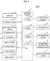
Fig. 1 is a diagram illustrating schematic configuration of an in-vehicle device according to one embodiment of the present invention. -
Fig. 2 is a diagram illustrating an example of a functional block of the in-vehicle device according to one embodiment of the present invention. -
Fig. 3 is a diagram illustrating a layout of split areas according to one embodiment of the present invention. -
Fig. 4(a) is a view illustrating an example of touch release detection regions O to R and a touch release position. -
Fig. 4(b) is a view illustrating an example of touch release detection regions E1 to E4 and touch release positions F1 to F4. -
Fig. 5(a) is a view illustrating a move of a pointer and a shape change of the split areas. -
Fig. 5(b) is a view illustrating a position N of the pointer and a change of the split areas before and after a touch release. -
Fig. 6(a) is a view illustrating a direction of a flick operation (or a swipe operation). -
Fig. 6(b) is a view illustrating a layout of the split areas changed based on the direction of the flick operation (or the swipe operation). -
Fig. 7(a) is a view illustrating display information displayed in a display form different for each type of the split areas. -
Fig. 7(b) is a view illustrating display information displayed in a display form different for each type of the split areas. -
Fig. 8(a) is a view illustrating the display information displayed in a display form different for each type of the split areas. -
Fig. 8(b) is a view illustrating the display information displayed in a display form different for each type of the split areas. -
Fig. 9 is a flowchart illustrating a flow of display area splitting processing according to one embodiment of the present invention. -
Fig. 10(a) is a view illustrating an example of the display information displayed in each of the split areas and a drag operation and a flick operation (or a swipe operation) of a pointer. -
Fig. 10(b) is a view illustrating a layout of the split areas changed by the drag operation and the flick operation (or the swipe operation) and an example of the display information displayed in the split areas after a change. -
Fig. 11(a) is a view illustrating an example of the display information displayed in each of the split areas and the drag operation and the flick operation (or the swipe operation) of the pointer. -
Fig. 11(b) is a view illustrating a layout of the split areas changed by the drag operation and the flick operation (or the swipe operation) and an example of the display information displayed in the split areas after a change. -
Fig. 12 is a table illustrating an example of display rule information according to one embodiment of the present invention. -
Fig. 13 is a view illustrating a layout change of the split display area in a case where a flick operation is performed on the display area with two fingers. -
Fig. 14(a) is a view illustrating an example of display contents that change according to the layout. -
Fig. 14(b) is a view illustrating an example of display contents that change according to the layout. - Hereinafter, one embodiment of the present invention is described.
-
Fig. 1 is a diagram illustrating schematic configuration of an in-vehicle device 100 according to this embodiment. The in-vehicle device 100 can be achieved, for example, by an in-vehicle navigation device having a navigation function. The navigation function referred to herein is a function provided to a normal navigation device such as displaying of map information, searching and guidance of a recommended route from a departure place (or a current place) to a destination place, and displaying of traffic information. Note that the in-vehicle device 100 is not limited to the navigation device and, for example, may also be a smart phone, a tablet terminal device, a personal data assistance (PDA), and the like. In this case, the navigation function is provided by application installed in these devices or a server device to which these devices can be connected. - As illustrated, the in-
vehicle device 100 includes anarithmetic processing device 1, adisplay 2, astorage device 3, an audio input/output device 4 (including amicrophone 41 as an audio input device and aspeaker 42 as an audio output device), aninput device 5, a read only memory (ROM)device 6, avehicle speed sensor 7, agyrosensor 8, a global positioning system (GPS)receiving device 9, a frequency modulation (FM) multiplexbroadcasting receiving device 10, and abeacon receiving device 11. - The
arithmetic processing device 1 is a central unit that performs various processing of the in-vehicle device 100. Thearithmetic processing device 1, for example, detects the current place using information output from various sensors such as thevehicle speed sensor 7 and theGPS receiving device 9. Based on information of the current place having been obtained, thearithmetic processing device 1 reads map information necessary for displaying the information from thestorage device 3 or theROM device 6. Thearithmetic processing device 1 expands the map information having been read into graphics and outputs a signal for displaying the graphics on thedisplay 2 by superimposing a mark indicating the current place thereon. Using the map information and the like stored in thestorage device 3 or theROM device 6, thearithmetic processing device 1 calculates a recommended route connecting a departure place with a destination place instructed by the user. Thearithmetic processing device 1 also performs guidance of the route by outputting a predetermined signal to thespeaker 42 and thedisplay 2. - The
arithmetic processing device 1 sets split areas obtained by splitting a display area at a predetermined ratio. Thearithmetic processing device 1 displays predetermined display information according to a layout of the split areas in each of the split areas in a predetermined display form. - Such
arithmetic processing device 1 includes: a central processing unit (CPU) 21 that executes various processing such as arithmetic operation and controlling of each of the devices; random access memory (RAM) 22 that temporarily stores the map information, arithmetic operation data, and the like read from a memory device such as thestorage device 3 andROM 23; theROM 23 that stores a boot program and the like achieved by theCPU 21; an interface (I/F) 24 for connecting various hardware with thearithmetic processing device 1; and abus 25 that connects these components with each other. - The
display 2 is a unit that displays graphics information. Thedisplay 2 is constituted of, for example, a liquid crystal display, an organic EL display, and the like. - The
storage device 3 is constituted of at least a readable and writable storage medium such as a hard disk drive (HDD) and a non-volatile memory card. Thestorage device 3 stores, for example, various information (e.g. map information, display rule information, and the like) used by thearithmetic processing device 1. Note that details of the display rule information are described below. - The audio input/
output device 4 includes themicrophone 41 as an audio input device and thespeaker 42 as an audio output device. Themicrophone 41 acquires audio outside of the in-vehicle device 100 such as a voice of a driver or a passenger (user speech) and the like. Thespeaker 42 outputs a guide for the driver and the like generated in thearithmetic processing device 1 as audio. - The
input device 5 is a device that receives input of an instruction from the user. Theinput device 5 is constituted of atouch panel 51, adial switch 52, and a hardware switch such as a scroll key, and the like (not illustrated). Theinput device 5 outputs information corresponding to operation of each key and each switch to another device such as thearithmetic processing device 1 and the like. - The
touch panel 51 is theinput device 5 installed on a display surface side of thedisplay 2 and installed such that a display screen thereof can be seen through. Thetouch panel 51 detects a touch by a human finger and a touch by a specialized touch pen. A touch position by the user is identified, for example, based on XY coordinates set on thetouch panel 51.Such touch panel 51 is constituted of, for example, an input detecting element of a capacitive sensing type and the like. - The
ROM device 6 is constituted of at least a readable storage medium such as ROM including a compact disk (CD)-ROM and a digital versatile disk (DVD)-ROM, and an integrated circuit (IC) card. The storage medium stores, for example, video data, audio data, and the like. - The
vehicle speed sensor 7 is a sensor that outputs a value used for calculating a vehicle speed. Thegyrosensor 8 is constituted of a fiber optic gyroscope, a vibratory gyroscope, and the like, and it is a sensor that detects an angular velocity due to rotation of a mobile body. TheGPS receiving device 9 measures a current place, a travel speed, and a travel azimuth of the mobile body by receiving a signal from a GPS satellite and by measuring a distance between the mobile body and the GPS satellite and a rate of change of the distance therebetween relative to three or more satellites. Each of the devices is used by thearithmetic processing device 1 for detecting the current place of a vehicle installed with the in-vehicle device 100. - The FM multiplex broadcasting receiving
device 10 receives an FM multiplex broadcasting signal transmitted from an FM broadcasting station. FM multiplex broadcasting includes VICS information such as outline present state traffic information, restriction information, service area (SA)/parking area (PA) information, parking lots information, and weather information as well as FM multiplex general information such as text information provided by a radio station. - The
beacon receiving device 11 receives the VICS information such as the outline present state traffic information, the restriction information, the SA/PA information, the parking lots information, the weather information, and an emergency alert. Thebeacon receiving device 11 may be, for example, an optical beacon that optically communicates, a radio wave beacon that communicates using radio wave, and the like. - As above, a hardware configuration of the in-
vehicle device 100 has been described. - Next, a functional block illustrating a functional configuration of the in-
vehicle device 100 is described.Fig. 2 is a diagram illustrating an example of the functional block of the in-vehicle device 100. The in-vehicle device 100 includes anarithmetic unit 101, and astorage unit 102. Further, thearithmetic unit 101 includes aninput receiving unit 111, anoperation detection unit 112, a displayarea setting unit 113, and a displayinformation generation unit 114. - The
input receiving unit 111 is a functional unit that receives an instruction from the user and input of information through the input device 5 (in this case, thedial switch 52 and the hardware switch) provided to the in-vehicle device 100. For example, theinput receiving unit 111 receives setting of a departure place and a destination place, a search instruction of a recommended route, and the like from the user through theinput device 5. - The
operation detection unit 112 is a functional unit that detects operation on thetouch panel 51 by a finger of the user or a specialized touch pen. Specifically, theoperation detection unit 112 detects a touch on thetouch panel 51, an operation of changing a touch position while holding the touch (hereinafter, referred to as a drag operation), and release of the touch. Theoperation detection unit 112 also identifies a coordinate position on thetouch panel 51 that is touched and a coordinate position at which the touch is released. - The
operation detection unit 112 detects an operation of moving the touch position on thetouch panel 51 in a fixed direction of up, down, left, or right (e.g. a flick operation or a swipe operation) and identifies the direction of the operation (direction of the flick operation or the swipe operation). The flick operation referred to herein is an operation of sliding the touch position on thetouch panel 51 in the fixed direction and releasing the touch from thetouch panel 51. Further, the swipe operation refers to an operation of sliding the touch position on thetouch panel 51 in the fixed direction. Note that the flick operation referred to hereinafter may also be the swipe operation in place of the flick operation. - The
operation detection unit 112 also detects multiple (e.g. two) touches on thetouch panel 51 within a predetermined time (e.g. 0.5 seconds) (hereinafter, referred to as a double-tap operation) and identifies coordinates on thetouch panel 51 indicating each of the touch positions. - When detecting such touch operation or touch release, the
operation detection unit 112 generates a signal associating a type of the touch, a coordinate position of the touch, a coordinate position of the touch release, a direction of the flick operation, and coordinates of each of the touch positions of the double-tap operation with each other, and outputs the signal to the displayarea setting unit 113. - The display
area setting unit 113 is a functional unit that sets the display area. Specifically, the displayarea setting unit 113 sets a full-screen area using an entire display area as one display area or split areas that are the full-screen area split into a predetermined number (e.g. four). - Here, the split areas set by the display
area setting unit 113 are described.Fig. 3 is a view illustrating layouts of the split areas. In alayout 1, a split area A occupying three-fourth of an entire screen (hereinafter, referred to as a "three-fourth screen") is set at a lower right position. The three-fourth screen is a similar figure of the full-screen area, which has a ratio of a long side to a short side of 16:9, and similar with the full-screen area, the three-fourth screen is configured to have a ratio of a long side to a short side of 16:9. By extending sides partitioning the three-fourth screen from an intersection point (pointer position N), a split area B (hereinafter, referred to as a "horizontal sub screen"), a split area C (hereinafter, referred to as a "vertical sub screen"), and a split area D (hereinafter, referred to as a "small sub screen") are set. Note that numerical values such as the ratio of the long side to the short side (16:9) and the occupied area (three-fourth) are not used in a strict meaning and may also include values within a range that can be regarded as substantially the same. - In a
layout 2, the three-fourth screen is set at a lower left position. In alayout 3, the three-fourth screen is set at an upper left position. In alayout 4, the three-fourth screen is set at an upper right position. Note that a size and a ratio of each of the split areas A to D according to thelayouts 2 to 4 are the same as those of thelayout 1. - The display
area setting unit 113 changes the layout of the display area based on the signal output from theoperation detection unit 112. For example, a case is described in which the touch operation is performed on a pointer in a state where the split areas of thelayout 1 are displayed. - When detecting that a user has performed a drag operation while touching the pointer, the
operation detection unit 112 detects a coordinate position of the pointer on thetouch panel 51 and periodically (e.g. every 0.1 seconds) outputs a signal associating the coordinate position with the type of the touch operation (here, the drag operation) to the displayarea setting unit 113. When detecting that the touch has been released, theoperation detection unit 112 outputs a signal associating the coordinate position with the type of the touch operation (here, the touch release) to the displayarea setting unit 113. When acquiring the signal, the displayarea setting unit 113 identifies in which region set on thetouch panel 51 is a touch release position included and determines the layout of the split areas. -
Fig. 4(a) is a view illustrating an example of touch release detection regions O to R and the touch release position. The displayarea setting unit 113 sets the touch release detection regions O to R on thedisplay 2. Such regions are obtained by splitting the full-screen area into four by connecting midpoints of the long side and the short side thereof. The displayarea setting unit 113 sets the split areas of thelayout 2 in a case where a touch on the pointer is released in the touch release detection region P (release positions S and T). The displayarea setting unit 113 sets the split areas of thelayout 3 in a case where the touch on the pointer is released in the touch release detection region Q (release positions U and V). The displayarea setting unit 113 sets the split areas of thelayout 4 in a case where the touch on the pointer is released in the touch release detection region R (release positions W and X). The displayarea setting unit 113 sets the split areas of thelayout 1 in a case where the touch on the pointer is released in the touch release detection region O (release positions Y and Z). - The display
area setting unit 113 sets the full-screen area in a case where the touch on the pointer is released in the vicinity of four corners of the display area.Fig. 4(b) is a view illustrating an example of touch release detection regions E1 to E4 and touch release positions F1 to F4. At the same time as setting the touch release detection regions O to R, the displayarea setting unit 113 also sets the touch release detection regions E1 to E4 on thedisplay 2. Each of such regions is a quarter circle region including an apex of the four corners of the display area. In a case where the touch on the pointer is released in any one of the touch release detection regions E1 to E4, the displayarea setting unit 113 sets the full-screen area as the display area. Note that in a case where the full-screen area is set, the displayarea setting unit 113 outputs a signal indicating coordinates of the touch release position to the displayinformation generation unit 114. - Note that the display
area setting unit 113 temporarily sets freely variable split areas while the pointer is moved and outputs a display instruction to the displayinformation generation unit 114.Fig. 5(a) is a view illustrating a move of the pointer and a change in shapes of the split areas. While the pointer is moved, that is at the time prior to acquiring the signal including the touch release position from theoperation detection unit 112, the displayarea setting unit 113 temporarily sets the split areas that are split into four using a coordinate position of the pointer, which is periodically acquired from theoperation detection unit 112, as the intersection point. The displayarea setting unit 113 outputs the display instruction of such split areas to the displayinformation generation unit 114. Accordingly, while the pointer is moved, the split areas that change shapes thereof according to the pointer position N are displayed. - When the touch release is detected by the
operation detection unit 112, the displayarea setting unit 113 determines any one of thelayouts 1 to 4 according to the release position and sets the split areas corresponding to such layout.Fig. 5(b) is a view illustrating the pointer position N and a change of the split areas before and after the touch release. When the touch on the pointer is released at a position i, the split areas that have temporarily been set and been displayed are changed into the split areas of thelayout 3. - When detecting that the user has performed the flick operation on the
touch panel 51, theoperation detection unit 112 identifies the type of the touch operation (here, the flick operation) and the direction of the flick operation and outputs a signal associating them with each other to the displayarea setting unit 113. The displayarea setting unit 113 determines the layout of the split areas based on the direction of the flick operation. -
Fig. 6(a) is a view illustrating a direction of the flick operation (or the swipe operation). When acquiring a signal indicating that the flick operation is made in the right direction, the displayarea setting unit 113 identifies the current layout of the split areas. For example, in a case where the split areas of thelayout 1 are displayed, the displayarea setting unit 113 identifies the layout of the split areas in which the pointer is moved in parallel in the right direction. That is, the displayarea setting unit 113 identifies thelayout 2 and sets the split areas according to such layout.Fig. 6(b) is a view illustrating the layout of the split areas changed based on the direction of the flick operation (or the swipe operation). - For example, when acquiring a signal indicating the flick operation is in a downward direction while the split areas of the
layout 2 are displayed, the displayarea setting unit 113 identifies the layout of the split areas in which the pointer is moved in parallel in the downward direction. That is, the displayarea setting unit 113 identifies thelayout 3 and sets the split areas according to the layout. - Further, when detecting that the user has performed the double-tap operation at any one of the four corners of the display area, the
operation detection unit 112 identifies coordinates on thetouch panel 51 indicating each of the touch positions, and transmits a signal associating the type of the touch operation (here, the double-tap operation) with each of the coordinate positions thereof to the displayarea setting unit 113. The displayarea setting unit 113 sets the full-screen area in a case where coordinates of each of the touch positions of the double-tap operation is included in any one region of the four corners of the display area. Note that in a case where the full-screen area is set by the double-tap operation, the displayarea setting unit 113 outputs a signal indicating the coordinate position that has been touched to the displayinformation generation unit 114. - Descriptions are given returning to
Fig. 2 . The displayinformation generation unit 114 is a functional unit that generates display information to be displayed in the display area. Specifically, the displayinformation generation unit 114 identifies the display information and the display form using the display rule information and displays the display information in the display form that has been identified. - The display rule information is information associating a display information type and an item thereof with a display form of each of the items for each type of the split area (the "full-screen area", "three-fourth screen", "horizontal sub screen", "vertical sub screen", and "small sub screen"). The display information type includes, for example, navigation-related display information, audio-related display information, tool-related display information, application content (APP)-related display information, and the like.
- Note that in a case where the display information type is navigation, the item thereof includes guidance information such as a map, a menu, a navigation setting, left and right turn information (arrow mark), and an intersection name. In a case where the display information type is audio, the item thereof includes each source, an image, play information of each of the sources, a basic operation button, and the like. In a case where the display information type is APP, the item thereof includes a launcher, each application, a fixed application, a launcher call button, and the like. Further, in a case where the display information type is a tool, the item thereof includes a clock, various indicators, various setting buttons, a custom button, and the like.
- In a case where any one of the
layouts 1 to 4 is set, the displayinformation generation unit 114 selects one split area among the split areas that are split into four, and identifies the type of the split areas. For example, in a case where the split area on the upper right in thelayout 1 is selected, the displayinformation generation unit 114 identifies that the split area is the horizontal sub screen. - The display
information generation unit 114 also identifies the display information type associated with the split area that has been selected. For example, the displayinformation generation unit 114 acquires predetermined information (not illustrated) including a correspondence relation between a position of each of the split areas and the display information type from a storage unit. Based on the information, the displayinformation generation unit 114 identifies the display information type associated with each of the split areas. - Using the display rule information, the display
information generation unit 114 also identifies the item of the display information and the display form to be displayed in each of the split areas. Specifically, based on the type of the split area and the display information type that have been identified, the displayinformation generation unit 114 identifies the item of the display information and the display form thereof from the display rule information, and displays the information in the split area. - In this way, the display
information generation unit 114 identifies the display information and the display form for all of the split areas in the layout that is set, and displays the information in each of the split areas. -
Figs. 7(a) and 7(b) andFigs. 8(a) and 8(b) are views illustrating the display information displayed in the display form different for each type of the split areas. Note that in this embodiment, the split area positioned on the upper right is associated with the audio as the display information type. InFig. 7(a) , since the type of the split area is the "three-fourth screen", more display information is displayed therein than in the split area of another type as the item of the display information such as text information, a music play progress bar, an album jacket, play time, a music operation button, and a list call button. - In
Fig. 7(b) , since the type of the split area is the "horizontal sub screen", the item of the display information suitable for the horizontally-long split area, that is, the text information, the play time, the music operation button, and the like are displayed. InFig. 8(a) , since the type of the split area is the "vertical sub screen", the item of the display information suitable for the vertically-long split area, that is, the text information, the play time, the album jacket, the music operation button, and the like are displayed. - In
Fig. 8(b) , since the type of the split area is the "small sub screen", the minimum-required item of the display information, that is, the music operation button is displayed. - In a case where the full-screen area is set, based on the signal acquired from the display
area setting unit 113, the displayinformation generation unit 114 identifies a touch release position or a coordinate position of the double-tap operation. The displayarea setting unit 113 also acquires predetermined information (not illustrated) including a correspondence relation between the coordinate position that has been identified and the display information type. Based on the information, the displayarea setting unit 113 identifies the display information type to be displayed on the full-screen area. As above, the displayinformation generation unit 114, identifies the item of the display information and the display form thereof to be displayed in the full-screen area using the display rule information, and displays the display information in the display form that has been identified. - The
storage unit 102 is a functional unit that stores the predetermined information. Specifically, thestorage unit 102 stores mapinformation 121,display rule information 122, and a variety of information (not illustrated). - As above, the functional block of the in-
vehicle device 100 is described. - Note that the
input receiving unit 111, theoperation detection unit 112, the displayarea setting unit 113, and the displayinformation generation unit 114 of the in-vehicle device 100 are achieved by a program that causes theCPU 21 to perform processing. The program is stored in theROM 23 or thestorage device 3 of the in-vehicle device 100. At the time of execution, the program is loaded on theRAM 22 and is executed by theCPU 21. - Each of the functional blocks has been classified according to main processing contents so as to facilitate understanding of functions of the in-
vehicle device 100 achieved in this embodiment. Thus, the present invention is not to be limited by a classification method or a name of each of the functions. Further, each configuration of the in-vehicle device 100 may be classified into more constituent elements according to processing contents thereof. It is also possible to classify such that one constituent element executes more processing. - All or part of each of the functional units may be constituted of hardware (integrated circuit such as ASIC) implemented on a computer. Processing of each of the functional units may be executed by one piece of hardware or may be executed by a plurality of pieces of hardware.
- Note that the
storage unit 102 of the in-vehicle device 100 is achieved by theROM 23 and thestorage device 3. - Next, display area splitting processing executed by the in-
vehicle device 100 is described.Fig. 9 is a flowchart illustrating a flow of the display area splitting processing. Such processing is started together with a startup of the in-vehicle device 100. - When the display area splitting processing is started, the
operation detection unit 112 determines whether or not a touch operation is received from a user (step S001). In a case where the touch operation is not received (No in step S001), theoperation detection unit 112 repeatedly executes processing of step S001. On the other hand, in a case where it has received the operation on the touch panel 51 (Yes in step S001), theoperation detection unit 112 shifts the processing to step S002. - Next, the
operation detection unit 112 identifies the type of the touch operation (step S002). For example, when identifying a touch and drag operation on a pointer, theoperation detection unit 112 detects a coordinate position of the pointer on thetouch panel 51 and periodically (e.g. every 0.1 seconds) outputs a signal associated with the type of the touch operation (in this case, the touch and drag operation) to the displayarea setting unit 113. Further, when detecting that the touch is released, theoperation detection unit 112 outputs a signal associated with the type of the touch operation (in this case, a touch release) and a coordinate position thereof to the displayarea setting unit 113. - Next, the display
area setting unit 113 performs setting of the split areas or the full-screen area (step S003). For example when acquiring the signal indicating the coordinate position at which the touch has been released from theoperation detection unit 112, the displayarea setting unit 113 identifies the touch release detection region (any one of O, P, Q, R, and E1 to E4) based on the coordinate position. For example, in a case where the coordinate position at which the touch has been released is any of the touch release detection regions O, P, Q, and R, the displayarea setting unit 113 determines the layout of the split areas and sets the split areas according to the layout. - Next, the display
information generation unit 114 identifies the display information and the display form (step S004). For example, the displayinformation generation unit 114 identifies the type of each of the split areas set by the displayarea setting unit 113. The displayinformation generation unit 114 acquires predetermined information (not illustrated) including a correspondence relation between a position of each of the split areas and the display information type from thestorage unit 102, and based on the type of the split areas and the display information type, it identifies the item of the display information and the display form to be displayed in each of the split areas from the display rule information. - Next, the display
information generation unit 114 generates the display information in the display form that has been identified (step S005), and displays the information in each of the split areas (step S006). The displayinformation generation unit 114 shifts the processing to step S001 and repeatedly executes the processing from steps S001 to S006. -
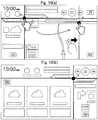
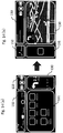
Figs. 10(a) and11(a) are views illustrating an example of the display information displayed in each of the split areas and the drag operation and the flick operation (or the swipe operation) of the pointer.Figs. 10(b) and11(b) are views illustrating the layout of the split areas changed by the drag operation and the flick operation (or the swipe operation) and an example of the display information displayed in the split areas after a change. - As illustrated in
Figs. 10 and11 , with the in-vehicle device 100 according to this embodiment, it is possible to display the display information suitable for a size and a shape of each of the split areas in an easier-to-see display form in a case where the layout of the split areas is changed. - With the in-
vehicle device 100 according to this embodiment, based on a position at which the touch on the pointer has been released and the direction of the flick operation, the split areas according to the one layout is applied among the layouts prepared in advance. Thus, it is not necessary to set the size and the shape of the split areas in detail. That is, an operation load on the user can be reduced compared to a case where the size and the shape of the split areas are freely variable by the user. - Further, with the in-
vehicle device 100 according to this embodiment, the split areas are set according to the predetermined layouts. Accordingly, compared to the case where setting of the split areas is freely variable by the user, a processing load on theCPU 21 can be reduced. - Still further, with the in-
vehicle device 100 according to this embodiment, it is possible to display by changing the number of and contents of items to be displayed for each of the display information types according to a change of the layout of the display area. Specifically, by identifying the item of the display information according to a shape type of the display area using thedisplay rule information 122, the displayinformation generation unit 114 identifies the number of and contents of the items to be displayed for each of the display information types. -
Fig. 12 is a table illustrating an example of thedisplay rule information 122. Thedisplay rule information 122 is information associating the display information type with the item thereof for each of the shape types of the display area. Specifically, for eachshape type 123 of the display area, thedisplay rule information 122 has a table associated with items related to the display information type such as navigation (NAVI) 124, audio (AUDIO) 125, application content (APP) 126, and a tool (TOOL) 127. - The
shape type 123 of the display area is information indicating a layout type of the display area and includes the full screen, the three-fourth screen, the horizontal sub screen (horizontal band screen), the vertical sub screen (vertical band screen), and the small sub screen (small screen). Theitems 124 to 127 of each of the display information types are information indicating the items to be displayed in the display area (split area). For example, theitem 124 of NAVI associated with the full screen and the three-fourth screen includes a map, a menu, a navigation setting, and the like. Theitem 124 of NAVI associated with the horizontal sub screen and the vertical sub screen includes left and right turn information, an intersection name, remaining distance, and the like as the guidance information. Further, theitem 124 of NAVI associated with the small sub screen includes the left and right turn information, the remaining distance, and the like as the guidance information. - For example, the
item 126 of APP associated with the full screen and the three-fourth screen includes a launcher, each of the applications, and the like. Theitem 126 of APP associated with the horizontal sub screen and the vertical sub screen includes a fixed application (specialized screen), a launcher call button, and the like. - In this way, in the
display rule information 122, a larger number of items or the items requiring a relatively large display area (e.g. the map, the launcher, and the like) are associated with the large display area shape type (e.g. the full screen and the three-fourth screen) compared to with the small display area shape type (e.g. the horizontal sub screen and the like). - By using such
display rule information 122, the displayinformation generation unit 114 identifies the items to be displayed in the display area (each of the split areas). -
Fig. 13 is a view illustrating a layout change of the display area in a case where a flick operation is performed on the display area with two fingers. - Specifically, when detecting that a user has performed a flick operation at predetermined coordinates on the
touch panel 51 displaying the map information with one finger, theoperation detection unit 112 transmits a signal associating the coordinate position with a direction of the flick operation to the displayinformation generation unit 114. When acquiring such signal, the displayinformation generation unit 114 generates screen information in which the map information is scrolled in the direction of the flick operation and displays the information on thedisplay 2. - On the other hand, when the
operation detection unit 112 detects that the user has performed a flick operation with two fingers, the displayinformation generation unit 114 changes the layout of the display area regardless of a position at which the fingers are released. - Accordingly, the in-
vehicle device 100 is capable of distinguishing between scrolling of the map due to the flic flick operation with one finger and a layout change of the display area due to the flick operation with two fingers, whereby it is possible to improve user operability and convenience of the in-vehicle device 100. -
Fig. 14 is a view illustrating an example of display contents that change according to a change from a layout of (a) to a layout of (b). As illustrated, the shape type of adisplay area 130 of NAVI in the layout of (a) before the change is the vertical sub screen. In this case, based on thedisplay rule information 122, the displayinformation generation unit 114 displays the left and right turn information and the remaining distance as the guidance information. When the shape type of thedisplay area 130 of NAVI becomes the three-fourth screen due to the change to the layout of (b), the displayinformation generation unit 114 displays a map, which is displayable in the large display area, the menu, and the navigation setting based on thedisplay rule information 122. - The shape type of a
display area 131 of APP in the layout of (a) before the change is the three-fourth screen. In this case, based on thedisplay rule information 122, the displayinformation generation unit 114 displays the launcher, each of the applications, and the like. When the shape type of thedisplay area 131 of APP becomes the vertical sub screen due to the change to the layout of (b), the displayinformation generation unit 114 displays the launcher call button, which is easier to be seen by the user even in the small display area, based on thedisplay rule information 122. - The shape type of a
display area 132 of TOOL in the layout of (a) before the change is the horizontal sub screen. In this case, based on thedisplay rule information 122, the displayinformation generation unit 114 displays a clock, various indicators, and the like. When the shape type of thedisplay area 132 of TOOL becomes the small sub screen due to the change to the layout of (b), the displayinformation generation unit 114 displays the predetermined number of (one in this example) and a predetermined type of (telephone in this example) icons according to the small display area based on thedisplay rule information 122. - The shape type of a
display area 133 of AUDIO in the layout of (a) before the change is the small sub screen. In this case, based on thedisplay rule information 122, the displayinformation generation unit 114 displays the basic operation button. When the shape type of thedisplay area 133 of AUDIO becomes the small sub screen due to the change to the layout of (b), the displayinformation generation unit 114 displays each source play information, which can be displayed in the display area larger than the small sub screen, and the basic operation button based on thedisplay rule information 122. - In this way, with the in-
vehicle device 100 according to this embodiment, by using thedisplay rule information 122, it is possible to display by changing the number of and contents of the items to be displayed for each of the display information types according to the change of the layout of the display area. For example, in a case where a large number of the items are displayed in the relatively small display area, it becomes difficult to be seen by the user. With the in-vehicle device 100 according to the present invention, such situation can be prevented by using the above-describeddisplay rule information 122. - With the in-
vehicle device 100, by using thedisplay rule information 122, it is also possible to control displaying and not displaying of the icons, which are touchable objects, according to the change of the layout of the display area. For example, in a case where a large number of the icons are displayed in the relatively small display area, the size thereof becomes small, and it becomes difficult to be touched by the user. In particular, since the user who is driving a vehicle has difficulties in visually recognizing the icons for a long time, the small-sized icons are more difficult to be touched. With the in-vehicle device 100 according to the present invention, such situation can be prevented by displaying the icons in the appropriate number and a form according to the display area by using the above-describeddisplay rule information 122. - When receiving a touch on the item or the icon displayed in the display area, the display
information generation unit 114 changes the display information displayed in the display area to the predetermined display information identified according to the type of the item or the icon that has been touched. For example, in a case where an icon indicating that music or the like is being "played" is displayed in the display area related to the audio, when receiving a touch on such icon, the displayinformation generation unit 114 changes the icon that has been touched to an icon indicating "stopped". For example, when receiving a touch on an icon indicating the predetermined application displayed in the display area related to APP, the displayinformation generation unit 114 displays screen information according to the application of the icon that has been touched (e.g. when a telephone application is touched, an incoming and outgoing call history, a numerical key pad for inputting a telephone number, and the like). - The present invention is not limited to the above-described embodiments and may include various embodiments and modifications other than the above-described embodiments. For example, the above-described embodiments have been described in detail in order to describe the present invention in an easy-to-understand manner and are not necessarily limited to those including all of the configurations described. It is possible to replace part of a configuration of one embodiment with a configuration of another embodiment or modification as well as to add a configuration of the other embodiment to the configuration of one embodiment. Further, part of the configuration of each of the embodiments may be added with another configuration, deleted, or replaced therewith.
- Part or all of the above-described configurations, functions, processing units, processing means, and the like may be achieved by a program that causes a processor to achieve each function. Information such as a program, a table, a file, and the like for achieving each of the functions may be placed in a storage device such as a memory, a hard disk, and a solid state drive (SSD) or a recording medium such as an IC card, a secure digital (SD) memory card, and a DVD. Note that a control line and an information line considered to be necessary for a description purpose have been illustrated, and not necessarily all of the control lines and the information lines within a product are illustrated.
-
- 100
- in-vehicle device
- 1
- arithmetic processing device
- 2
- display
- 3
- storage device
- 4
- audio input/output device
- 41
- microphone
- 42
- speaker
- 5
- input device
- 51
- touch panel
- 52
- dial switch
- 6
- ROM device
- 7
- vehicle speed sensor
- 8
- gyrosensor
- 9
- GPS receiving device
- 10
- FM multiplex broadcasting receiving device
- 11
- beacon receiving device
- 101
- arithmetic unit
- 102
- storage unit
- 111
- input receiving unit
- 112
- operation detection unit
- 113
- display area setting unit
- 114
- display information generation unit
- 121
- map information
- 122
- display rule information
Claims (13)
- An in-vehicle device including a display unit having a display area, the in-vehicle device comprising:an operation detection unit configured to detect an operation on a touch panel;a split area setting unit configured to identify one layout among predetermined layouts related to split areas obtained by splitting the display area on the basis of the operation having been detected, and to set the split areas according to the layout having been identified; anda display information generation unit configured to identify an item and a display form of display information for each of the split areas on the basis of a display information type and a shape type of each of the split areas corresponding to a setting position of each of the split areas, and to display the display information in the corresponding split area in the display form having been identified.
- The in-vehicle device according to claim 1, wherein t
he split area setting unit
identifies the layout of the split areas on the basis of a release position of the operation detected by the operation detection unit. - The in-vehicle device according to claim 1, wherein
the split area setting unit
identifies the layout of the split areas on the basis of an operation direction on the touch panel detected by the operation detection unit. - The in-vehicle device according to claim 1, wherein
the split area setting unit
sets a full-screen area in which an entire screen is one display area on the basis of a release position of the operation or a touch position and the number of touches detected by the operation detection unit, and
the display information generation unit
identifies the item and the display form of the display information on the basis of the display information type associated with the release position of the operation or the touch position and the shape type of the display area, and
displays the display information in the display form having been identified. - The in-vehicle device according to claim 1, wherein
the layout of the split areas is constituted of
a split area being a similar figure of the entire display area and occupying substantially three-fourth of the entire display area, and
a plurality of split areas formed by extending a long side and a short side partitioning the split area being the similar figure. - A display area splitting method executed by an in-vehicle device including a display unit having a display area, wherein
the in-vehicle device performs the steps of:detecting operation on the touch panel;split area setting of identifying one layout among the predetermined layouts related to split areas obtained by splitting the display area on the basis of the operation having been detected, and setting the split areas according to the layout having been identified; andidentifying an item and a display form of display information for each of the split areas on the basis of a display information type and a shape type of each of the split areas corresponding to a setting position of each of the split areas, and displaying the display information in the corresponding split area in the display form having been identified. - A program causing a computer to function as an in-vehicle device including a display unit having a display area, wherein
the computer is caused to function as;
an operation detection unit configured to detect an operation on the touch panel;
a split area setting unit configured to identify one layout among the predetermined layouts related to split areas obtained by splitting the display area on the basis of the operation having been detected, and to set the split areas according to layout having been identified; and
a display information generation unit configured to identify an item and a display form of display information for each of the split areas on the basis of a display information type and a shape type of each of the split areas corresponding to a setting position of each of the split areas, and to display the display information in the corresponding split area in the display form having been identified. - An information control device comprising:a storage unit configured to store multiple types of layouts of a display area including a first display area displaying first information and a second display area displaying second information; anda controller configured to determine the first information displayed in the first display area and the second information displayed in the second display area, whereinthe controllerselects any of the multiple types of layouts based on a position at which contact on a touch panel is released.
- The information control device according to claim 8, wherein
the controller
selects a first layout when the position at which the contact on the touch panel is released is within the first display area, and
selects a second layout when the position at which the contact on the touch panel is released is within the second display area. - The information control device according to claim 8 or 9, wherein
when the contact on the touch panel is released, the controller moves a partition line partitioning one display area from another display area and an intersection point of the partition lines according to a release position to a predetermined position corresponding to the layout. - The information control device according to any one of claims 8 to 10, wherein
when contact on a touch panel is performed in a first aspect, the controller selects any of the multiple types of the layouts based on a position at which the contact on the touch panel is released, and
when the contact on the touch panel is performed in a second aspect, the controller selects any of the multiple types of the layouts based on a direction identified by a position at which the contact on the touch panel is performed and the position at which the contact on the touch panel is released. - The information control device according to any one of claims 8 to 11, wherein
the controller
displays a display item included in the first information displayed in the first display area when the first layout is selected differently from a display item included in the first information displayed in the first display area when the second layout is selected. - The information control device according to claim 12, wherein
when contact is performed on the display item, the controller changes display of the first information displayed in the first display area.
Applications Claiming Priority (2)
| Application Number | Priority Date | Filing Date | Title |
|---|---|---|---|
| JP2015249794 | 2015-12-22 | ||
| PCT/JP2016/088474 WO2017111075A1 (en) | 2015-12-22 | 2016-12-22 | On-board device, display area dividing method, program, and information control device |
Publications (3)
| Publication Number | Publication Date |
|---|---|
| EP3396514A1 true EP3396514A1 (en) | 2018-10-31 |
| EP3396514A4 EP3396514A4 (en) | 2019-07-31 |
| EP3396514B1 EP3396514B1 (en) | 2022-05-04 |
Family
ID=59090500
Family Applications (1)
| Application Number | Title | Priority Date | Filing Date |
|---|---|---|---|
| EP16878961.8A Active EP3396514B1 (en) | 2015-12-22 | 2016-12-22 | Display area dividing device, method and computer program |
Country Status (5)
| Country | Link |
|---|---|
| US (1) | US10936188B2 (en) |
| EP (1) | EP3396514B1 (en) |
| JP (1) | JP6838563B2 (en) |
| CN (1) | CN108431757B (en) |
| WO (1) | WO2017111075A1 (en) |
Cited By (2)
| Publication number | Priority date | Publication date | Assignee | Title |
|---|---|---|---|---|
| WO2021125180A1 (en) * | 2019-12-18 | 2021-06-24 | Clarion Co., Ltd. | Display control device and display control method |
| WO2021125179A1 (en) * | 2019-12-18 | 2021-06-24 | Clarion Co., Ltd. | Display control device and display control method |
Families Citing this family (8)
| Publication number | Priority date | Publication date | Assignee | Title |
|---|---|---|---|---|
| JP7093690B2 (en) * | 2018-07-05 | 2022-06-30 | フォルシアクラリオン・エレクトロニクス株式会社 | Information control device and display change method |
| JP7129248B2 (en) * | 2018-07-05 | 2022-09-01 | フォルシアクラリオン・エレクトロニクス株式会社 | Information control device and display change method |
| JP7202876B2 (en) * | 2018-12-25 | 2023-01-12 | フォルシアクラリオン・エレクトロニクス株式会社 | Display control device and display control method |
| JP2020135627A (en) * | 2019-02-22 | 2020-08-31 | パイオニア株式会社 | Information display device, information display method and program |
| JP7223624B2 (en) * | 2019-04-12 | 2023-02-16 | フォルシアクラリオン・エレクトロニクス株式会社 | Display control device and display control method |
| JP7214542B2 (en) * | 2019-04-12 | 2023-01-30 | フォルシアクラリオン・エレクトロニクス株式会社 | Display control device and display control method |
| JP7474179B2 (en) * | 2020-10-22 | 2024-04-24 | フォルシアクラリオン・エレクトロニクス株式会社 | Display control device and display control method |
| CN117971152B (en) * | 2024-04-02 | 2024-06-28 | 长城汽车股份有限公司 | Display method and device for vehicle display screen and vehicle |
Family Cites Families (31)
| Publication number | Priority date | Publication date | Assignee | Title |
|---|---|---|---|---|
| DE3707490A1 (en) * | 1987-03-09 | 1988-09-22 | Siemens Ag | ARRANGEMENT FOR THE SIMULTANEOUS DISPLAY OF SEVERAL IMAGES ON THE SCREEN OF A VIEWING DEVICE |
| US20020191028A1 (en) * | 2001-06-19 | 2002-12-19 | Senechalle David A. | Window manager user interface |
| WO2004063917A2 (en) * | 2003-01-14 | 2004-07-29 | Koninklijke Philips Electronics N.V. | Rearranging views on a computer screen |
| US7480872B1 (en) * | 2003-04-06 | 2009-01-20 | Apple Inc. | Method and apparatus for dynamically resizing windows |
| JP2005038064A (en) * | 2003-07-16 | 2005-02-10 | Fuji Electric Holdings Co Ltd | Screen layout setting program and program storage medium |
| US20050280524A1 (en) * | 2004-06-18 | 2005-12-22 | Applied Digital, Inc. | Vehicle entertainment and accessory control system |
| JP4650141B2 (en) * | 2005-07-25 | 2011-03-16 | 富士ゼロックス株式会社 | Information processing apparatus and information processing program |
| US7770109B2 (en) * | 2005-12-16 | 2010-08-03 | Microsoft Corporation | Adaptive layout for content |
| US7694221B2 (en) * | 2006-02-28 | 2010-04-06 | Microsoft Corporation | Choosing between multiple versions of content to optimize display |
| JP4700539B2 (en) * | 2006-03-22 | 2011-06-15 | パナソニック株式会社 | Display device |
| US7773075B2 (en) | 2006-03-22 | 2010-08-10 | Panasonic Corporation | Display apparatus |
| JP2008085546A (en) | 2006-09-27 | 2008-04-10 | Funai Electric Co Ltd | Video output device |
| JP4449996B2 (en) | 2007-03-09 | 2010-04-14 | 船井電機株式会社 | Television broadcast signal receiver |
| JP2009229172A (en) * | 2008-03-21 | 2009-10-08 | Alpine Electronics Inc | Information-providing system and information-providing method |
| JP2011089820A (en) * | 2009-10-21 | 2011-05-06 | Clarion Co Ltd | Navigation device and display method therefor |
| US8208964B2 (en) * | 2009-10-30 | 2012-06-26 | Cellco Partnership | Flexible home page layout for mobile devices |
| JP4975129B2 (en) * | 2010-03-23 | 2012-07-11 | シャープ株式会社 | Operating device, electronic device and image processing apparatus including the operating device, and information display method in the operating device |
| JP2012123477A (en) | 2010-12-06 | 2012-06-28 | Fujitsu Ten Ltd | Shortcut icon registration method |
| US20120159314A1 (en) * | 2010-12-16 | 2012-06-21 | Microsoft Corporation | Adaptive content layout |
| CN102053795B (en) * | 2011-01-11 | 2012-10-24 | 华平信息技术股份有限公司 | Method and system for freely laying out video display window |
| JP5752572B2 (en) * | 2011-11-24 | 2015-07-22 | シャープ株式会社 | Display control apparatus, display method, control program, and recording medium |
| JP5649229B2 (en) | 2012-04-26 | 2015-01-07 | 京セラドキュメントソリューションズ株式会社 | Display input device and image forming apparatus |
| TWI486870B (en) * | 2013-01-23 | 2015-06-01 | Acti Corp | Dynamically control how to split the window size |
| US10152459B2 (en) * | 2013-02-20 | 2018-12-11 | Google Llc | Intelligent window placement with multiple windows using high DPI screens |
| EP2796980B1 (en) | 2013-04-26 | 2019-04-10 | Spreadtrum Communications (Shanghai) Co., Ltd. | Apparatus and method for setting a two hand mode to operate a touchscreen |
| US10775971B2 (en) * | 2013-06-28 | 2020-09-15 | Successfactors, Inc. | Pinch gestures in a tile-based user interface |
| KR101801554B1 (en) * | 2013-07-11 | 2017-11-27 | 삼성전자주식회사 | User terminal device for displaying contents and methods thereof |
| JP6098435B2 (en) * | 2013-08-22 | 2017-03-22 | ソニー株式会社 | Information processing apparatus, storage medium, and control method |
| KR20150029451A (en) * | 2013-09-10 | 2015-03-18 | 엘지전자 주식회사 | Mobile terminal and method for controlling the same |
| JP6151157B2 (en) | 2013-10-29 | 2017-06-21 | 京セラ株式会社 | Electronic device, control program, and operation method of electronic device |
| JP2015208602A (en) | 2014-04-30 | 2015-11-24 | 株式会社日立メディコ | Image display device and image display method |
-
2016
- 2016-12-22 EP EP16878961.8A patent/EP3396514B1/en active Active
- 2016-12-22 WO PCT/JP2016/088474 patent/WO2017111075A1/en not_active Ceased
- 2016-12-22 CN CN201680074771.2A patent/CN108431757B/en active Active
- 2016-12-22 US US16/064,601 patent/US10936188B2/en active Active
- 2016-12-22 JP JP2017558281A patent/JP6838563B2/en active Active
Cited By (7)
| Publication number | Priority date | Publication date | Assignee | Title |
|---|---|---|---|---|
| WO2021125180A1 (en) * | 2019-12-18 | 2021-06-24 | Clarion Co., Ltd. | Display control device and display control method |
| WO2021125179A1 (en) * | 2019-12-18 | 2021-06-24 | Clarion Co., Ltd. | Display control device and display control method |
| CN114830075A (en) * | 2019-12-18 | 2022-07-29 | 佛吉亚歌乐电子有限公司 | Display control device and display control method |
| CN114846439A (en) * | 2019-12-18 | 2022-08-02 | 佛吉亚歌乐电子有限公司 | Display control device and display control method |
| US11693545B2 (en) | 2019-12-18 | 2023-07-04 | Faurecia Clarion Electronics Co., Ltd. | Device and method for arranging objects displayed on divided areas in a vehicle display |
| US11942011B2 (en) | 2019-12-18 | 2024-03-26 | Faurecia Clarion Electronics Co., Ltd. | Display control device and display control method |
| CN114830075B (en) * | 2019-12-18 | 2025-05-02 | 佛吉亚歌乐电子有限公司 | Display control device and display control method |
Also Published As
| Publication number | Publication date |
|---|---|
| JP6838563B2 (en) | 2021-03-03 |
| EP3396514B1 (en) | 2022-05-04 |
| CN108431757B (en) | 2022-09-06 |
| WO2017111075A1 (en) | 2017-06-29 |
| US20190012078A1 (en) | 2019-01-10 |
| CN108431757A (en) | 2018-08-21 |
| EP3396514A4 (en) | 2019-07-31 |
| US10936188B2 (en) | 2021-03-02 |
| JPWO2017111075A1 (en) | 2018-10-11 |
Similar Documents
| Publication | Publication Date | Title |
|---|---|---|
| EP3396514B1 (en) | Display area dividing device, method and computer program | |
| US11334211B2 (en) | Information control device and method for changing display region sizes and positional relationships | |
| JP7202876B2 (en) | Display control device and display control method | |
| EP4078354B1 (en) | Display control device and display control method | |
| US12118204B2 (en) | Display control device and display change method with user touch control | |
| EP4078352B1 (en) | Display control device and display control method | |
| EP4078353B1 (en) | Display control device and display control method | |
| JP7153486B2 (en) | Information control device and display change method | |
| JP2018195178A (en) | Information control apparatus and display area dividing method of information control apparatus |
Legal Events
| Date | Code | Title | Description |
|---|---|---|---|
| STAA | Information on the status of an ep patent application or granted ep patent |
Free format text: STATUS: THE INTERNATIONAL PUBLICATION HAS BEEN MADE |
|
| PUAI | Public reference made under article 153(3) epc to a published international application that has entered the european phase |
Free format text: ORIGINAL CODE: 0009012 |
|
| STAA | Information on the status of an ep patent application or granted ep patent |
Free format text: STATUS: REQUEST FOR EXAMINATION WAS MADE |
|
| 17P | Request for examination filed |
Effective date: 20180622 |
|
| AK | Designated contracting states |
Kind code of ref document: A1 Designated state(s): AL AT BE BG CH CY CZ DE DK EE ES FI FR GB GR HR HU IE IS IT LI LT LU LV MC MK MT NL NO PL PT RO RS SE SI SK SM TR |
|
| AX | Request for extension of the european patent |
Extension state: BA ME |
|
| DAV | Request for validation of the european patent (deleted) | ||
| DAX | Request for extension of the european patent (deleted) | ||
| RIC1 | Information provided on ipc code assigned before grant |
Ipc: G06F 3/0488 20130101ALI20190618BHEP Ipc: G06F 3/0484 20130101AFI20190618BHEP |
|
| A4 | Supplementary search report drawn up and despatched |
Effective date: 20190627 |
|
| STAA | Information on the status of an ep patent application or granted ep patent |
Free format text: STATUS: EXAMINATION IS IN PROGRESS |
|
| 17Q | First examination report despatched |
Effective date: 20200327 |
|
| GRAP | Despatch of communication of intention to grant a patent |
Free format text: ORIGINAL CODE: EPIDOSNIGR1 |
|
| STAA | Information on the status of an ep patent application or granted ep patent |
Free format text: STATUS: GRANT OF PATENT IS INTENDED |
|
| INTG | Intention to grant announced |
Effective date: 20211215 |
|
| GRAS | Grant fee paid |
Free format text: ORIGINAL CODE: EPIDOSNIGR3 |
|
| GRAA | (expected) grant |
Free format text: ORIGINAL CODE: 0009210 |
|
| STAA | Information on the status of an ep patent application or granted ep patent |
Free format text: STATUS: THE PATENT HAS BEEN GRANTED |
|
| AK | Designated contracting states |
Kind code of ref document: B1 Designated state(s): AL AT BE BG CH CY CZ DE DK EE ES FI FR GB GR HR HU IE IS IT LI LT LU LV MC MK MT NL NO PL PT RO RS SE SI SK SM TR |
|
| REG | Reference to a national code |
Ref country code: GB Ref legal event code: FG4D |
|
| REG | Reference to a national code |
Ref country code: CH Ref legal event code: EP |
|
| REG | Reference to a national code |
Ref country code: AT Ref legal event code: REF Ref document number: 1489784 Country of ref document: AT Kind code of ref document: T Effective date: 20220515 |
|
| REG | Reference to a national code |
Ref country code: DE Ref legal event code: R096 Ref document number: 602016071906 Country of ref document: DE |
|
| REG | Reference to a national code |
Ref country code: IE Ref legal event code: FG4D |
|
| REG | Reference to a national code |
Ref country code: LT Ref legal event code: MG9D |
|
| REG | Reference to a national code |
Ref country code: NL Ref legal event code: MP Effective date: 20220504 |
|
| REG | Reference to a national code |
Ref country code: AT Ref legal event code: MK05 Ref document number: 1489784 Country of ref document: AT Kind code of ref document: T Effective date: 20220504 |
|
| PG25 | Lapsed in a contracting state [announced via postgrant information from national office to epo] |
Ref country code: SE Free format text: LAPSE BECAUSE OF FAILURE TO SUBMIT A TRANSLATION OF THE DESCRIPTION OR TO PAY THE FEE WITHIN THE PRESCRIBED TIME-LIMIT Effective date: 20220504 Ref country code: PT Free format text: LAPSE BECAUSE OF FAILURE TO SUBMIT A TRANSLATION OF THE DESCRIPTION OR TO PAY THE FEE WITHIN THE PRESCRIBED TIME-LIMIT Effective date: 20220905 Ref country code: NO Free format text: LAPSE BECAUSE OF FAILURE TO SUBMIT A TRANSLATION OF THE DESCRIPTION OR TO PAY THE FEE WITHIN THE PRESCRIBED TIME-LIMIT Effective date: 20220804 Ref country code: NL Free format text: LAPSE BECAUSE OF FAILURE TO SUBMIT A TRANSLATION OF THE DESCRIPTION OR TO PAY THE FEE WITHIN THE PRESCRIBED TIME-LIMIT Effective date: 20220504 Ref country code: LT Free format text: LAPSE BECAUSE OF FAILURE TO SUBMIT A TRANSLATION OF THE DESCRIPTION OR TO PAY THE FEE WITHIN THE PRESCRIBED TIME-LIMIT Effective date: 20220504 Ref country code: HR Free format text: LAPSE BECAUSE OF FAILURE TO SUBMIT A TRANSLATION OF THE DESCRIPTION OR TO PAY THE FEE WITHIN THE PRESCRIBED TIME-LIMIT Effective date: 20220504 Ref country code: GR Free format text: LAPSE BECAUSE OF FAILURE TO SUBMIT A TRANSLATION OF THE DESCRIPTION OR TO PAY THE FEE WITHIN THE PRESCRIBED TIME-LIMIT Effective date: 20220805 Ref country code: FI Free format text: LAPSE BECAUSE OF FAILURE TO SUBMIT A TRANSLATION OF THE DESCRIPTION OR TO PAY THE FEE WITHIN THE PRESCRIBED TIME-LIMIT Effective date: 20220504 Ref country code: ES Free format text: LAPSE BECAUSE OF FAILURE TO SUBMIT A TRANSLATION OF THE DESCRIPTION OR TO PAY THE FEE WITHIN THE PRESCRIBED TIME-LIMIT Effective date: 20220504 Ref country code: BG Free format text: LAPSE BECAUSE OF FAILURE TO SUBMIT A TRANSLATION OF THE DESCRIPTION OR TO PAY THE FEE WITHIN THE PRESCRIBED TIME-LIMIT Effective date: 20220804 Ref country code: AT Free format text: LAPSE BECAUSE OF FAILURE TO SUBMIT A TRANSLATION OF THE DESCRIPTION OR TO PAY THE FEE WITHIN THE PRESCRIBED TIME-LIMIT Effective date: 20220504 |
|
| PG25 | Lapsed in a contracting state [announced via postgrant information from national office to epo] |
Ref country code: RS Free format text: LAPSE BECAUSE OF FAILURE TO SUBMIT A TRANSLATION OF THE DESCRIPTION OR TO PAY THE FEE WITHIN THE PRESCRIBED TIME-LIMIT Effective date: 20220504 Ref country code: PL Free format text: LAPSE BECAUSE OF FAILURE TO SUBMIT A TRANSLATION OF THE DESCRIPTION OR TO PAY THE FEE WITHIN THE PRESCRIBED TIME-LIMIT Effective date: 20220504 Ref country code: LV Free format text: LAPSE BECAUSE OF FAILURE TO SUBMIT A TRANSLATION OF THE DESCRIPTION OR TO PAY THE FEE WITHIN THE PRESCRIBED TIME-LIMIT Effective date: 20220504 Ref country code: IS Free format text: LAPSE BECAUSE OF FAILURE TO SUBMIT A TRANSLATION OF THE DESCRIPTION OR TO PAY THE FEE WITHIN THE PRESCRIBED TIME-LIMIT Effective date: 20220904 |
|
| PG25 | Lapsed in a contracting state [announced via postgrant information from national office to epo] |
Ref country code: SM Free format text: LAPSE BECAUSE OF FAILURE TO SUBMIT A TRANSLATION OF THE DESCRIPTION OR TO PAY THE FEE WITHIN THE PRESCRIBED TIME-LIMIT Effective date: 20220504 Ref country code: SK Free format text: LAPSE BECAUSE OF FAILURE TO SUBMIT A TRANSLATION OF THE DESCRIPTION OR TO PAY THE FEE WITHIN THE PRESCRIBED TIME-LIMIT Effective date: 20220504 Ref country code: RO Free format text: LAPSE BECAUSE OF FAILURE TO SUBMIT A TRANSLATION OF THE DESCRIPTION OR TO PAY THE FEE WITHIN THE PRESCRIBED TIME-LIMIT Effective date: 20220504 Ref country code: EE Free format text: LAPSE BECAUSE OF FAILURE TO SUBMIT A TRANSLATION OF THE DESCRIPTION OR TO PAY THE FEE WITHIN THE PRESCRIBED TIME-LIMIT Effective date: 20220504 Ref country code: DK Free format text: LAPSE BECAUSE OF FAILURE TO SUBMIT A TRANSLATION OF THE DESCRIPTION OR TO PAY THE FEE WITHIN THE PRESCRIBED TIME-LIMIT Effective date: 20220504 Ref country code: CZ Free format text: LAPSE BECAUSE OF FAILURE TO SUBMIT A TRANSLATION OF THE DESCRIPTION OR TO PAY THE FEE WITHIN THE PRESCRIBED TIME-LIMIT Effective date: 20220504 |
|
| REG | Reference to a national code |
Ref country code: DE Ref legal event code: R097 Ref document number: 602016071906 Country of ref document: DE |
|
| PLBE | No opposition filed within time limit |
Free format text: ORIGINAL CODE: 0009261 |
|
| STAA | Information on the status of an ep patent application or granted ep patent |
Free format text: STATUS: NO OPPOSITION FILED WITHIN TIME LIMIT |
|
| PG25 | Lapsed in a contracting state [announced via postgrant information from national office to epo] |
Ref country code: AL Free format text: LAPSE BECAUSE OF FAILURE TO SUBMIT A TRANSLATION OF THE DESCRIPTION OR TO PAY THE FEE WITHIN THE PRESCRIBED TIME-LIMIT Effective date: 20220504 |
|
| 26N | No opposition filed |
Effective date: 20230207 |
|
| PG25 | Lapsed in a contracting state [announced via postgrant information from national office to epo] |
Ref country code: SI Free format text: LAPSE BECAUSE OF FAILURE TO SUBMIT A TRANSLATION OF THE DESCRIPTION OR TO PAY THE FEE WITHIN THE PRESCRIBED TIME-LIMIT Effective date: 20220504 |
|
| REG | Reference to a national code |
Ref country code: CH Ref legal event code: PL |
|
| GBPC | Gb: european patent ceased through non-payment of renewal fee |
Effective date: 20221222 |
|
| REG | Reference to a national code |
Ref country code: BE Ref legal event code: MM Effective date: 20221231 |
|
| PG25 | Lapsed in a contracting state [announced via postgrant information from national office to epo] |
Ref country code: LU Free format text: LAPSE BECAUSE OF NON-PAYMENT OF DUE FEES Effective date: 20221222 |
|
| PG25 | Lapsed in a contracting state [announced via postgrant information from national office to epo] |
Ref country code: LI Free format text: LAPSE BECAUSE OF NON-PAYMENT OF DUE FEES Effective date: 20221231 Ref country code: IE Free format text: LAPSE BECAUSE OF NON-PAYMENT OF DUE FEES Effective date: 20221222 Ref country code: GB Free format text: LAPSE BECAUSE OF NON-PAYMENT OF DUE FEES Effective date: 20221222 Ref country code: CH Free format text: LAPSE BECAUSE OF NON-PAYMENT OF DUE FEES Effective date: 20221231 |
|
| PG25 | Lapsed in a contracting state [announced via postgrant information from national office to epo] |
Ref country code: BE Free format text: LAPSE BECAUSE OF NON-PAYMENT OF DUE FEES Effective date: 20221231 |
|
| PG25 | Lapsed in a contracting state [announced via postgrant information from national office to epo] |
Ref country code: IT Free format text: LAPSE BECAUSE OF FAILURE TO SUBMIT A TRANSLATION OF THE DESCRIPTION OR TO PAY THE FEE WITHIN THE PRESCRIBED TIME-LIMIT Effective date: 20220504 |
|
| PG25 | Lapsed in a contracting state [announced via postgrant information from national office to epo] |
Ref country code: HU Free format text: LAPSE BECAUSE OF FAILURE TO SUBMIT A TRANSLATION OF THE DESCRIPTION OR TO PAY THE FEE WITHIN THE PRESCRIBED TIME-LIMIT; INVALID AB INITIO Effective date: 20161222 |
|
| PG25 | Lapsed in a contracting state [announced via postgrant information from national office to epo] |
Ref country code: CY Free format text: LAPSE BECAUSE OF FAILURE TO SUBMIT A TRANSLATION OF THE DESCRIPTION OR TO PAY THE FEE WITHIN THE PRESCRIBED TIME-LIMIT Effective date: 20220504 |
|
| PG25 | Lapsed in a contracting state [announced via postgrant information from national office to epo] |
Ref country code: MK Free format text: LAPSE BECAUSE OF FAILURE TO SUBMIT A TRANSLATION OF THE DESCRIPTION OR TO PAY THE FEE WITHIN THE PRESCRIBED TIME-LIMIT Effective date: 20220504 |
|
| PG25 | Lapsed in a contracting state [announced via postgrant information from national office to epo] |
Ref country code: MC Free format text: LAPSE BECAUSE OF FAILURE TO SUBMIT A TRANSLATION OF THE DESCRIPTION OR TO PAY THE FEE WITHIN THE PRESCRIBED TIME-LIMIT Effective date: 20220504 |
|
| PG25 | Lapsed in a contracting state [announced via postgrant information from national office to epo] |
Ref country code: MC Free format text: LAPSE BECAUSE OF FAILURE TO SUBMIT A TRANSLATION OF THE DESCRIPTION OR TO PAY THE FEE WITHIN THE PRESCRIBED TIME-LIMIT Effective date: 20220504 |
|
| PG25 | Lapsed in a contracting state [announced via postgrant information from national office to epo] |
Ref country code: MT Free format text: LAPSE BECAUSE OF FAILURE TO SUBMIT A TRANSLATION OF THE DESCRIPTION OR TO PAY THE FEE WITHIN THE PRESCRIBED TIME-LIMIT Effective date: 20220504 |
|
| PG25 | Lapsed in a contracting state [announced via postgrant information from national office to epo] |
Ref country code: BG Free format text: LAPSE BECAUSE OF FAILURE TO SUBMIT A TRANSLATION OF THE DESCRIPTION OR TO PAY THE FEE WITHIN THE PRESCRIBED TIME-LIMIT Effective date: 20220504 |
|
| PG25 | Lapsed in a contracting state [announced via postgrant information from national office to epo] |
Ref country code: BG Free format text: LAPSE BECAUSE OF FAILURE TO SUBMIT A TRANSLATION OF THE DESCRIPTION OR TO PAY THE FEE WITHIN THE PRESCRIBED TIME-LIMIT Effective date: 20220504 |
|
| PG25 | Lapsed in a contracting state [announced via postgrant information from national office to epo] |
Ref country code: TR Free format text: LAPSE BECAUSE OF FAILURE TO SUBMIT A TRANSLATION OF THE DESCRIPTION OR TO PAY THE FEE WITHIN THE PRESCRIBED TIME-LIMIT Effective date: 20220504 |
|
| PGFP | Annual fee paid to national office [announced via postgrant information from national office to epo] |
Ref country code: DE Payment date: 20251126 Year of fee payment: 10 |
|
| PGFP | Annual fee paid to national office [announced via postgrant information from national office to epo] |
Ref country code: FR Payment date: 20251119 Year of fee payment: 10 |