EP3396246B1 - Exhaust gas system with measurement site system - Google Patents
Exhaust gas system with measurement site system Download PDFInfo
- Publication number
- EP3396246B1 EP3396246B1 EP17167807.1A EP17167807A EP3396246B1 EP 3396246 B1 EP3396246 B1 EP 3396246B1 EP 17167807 A EP17167807 A EP 17167807A EP 3396246 B1 EP3396246 B1 EP 3396246B1
- Authority
- EP
- European Patent Office
- Prior art keywords
- line component
- closure element
- external line
- opening
- exhaust gas
- Prior art date
- Legal status (The legal status is an assumption and is not a legal conclusion. Google has not performed a legal analysis and makes no representation as to the accuracy of the status listed.)
- Active
Links
- 238000005259 measurement Methods 0.000 title claims description 32
- 238000007789 sealing Methods 0.000 claims description 53
- 230000000903 blocking effect Effects 0.000 claims description 18
- 238000013459 approach Methods 0.000 claims description 5
- 230000001174 ascending effect Effects 0.000 claims 3
- 239000012530 fluid Substances 0.000 description 8
- 230000000630 rising effect Effects 0.000 description 6
- 239000000523 sample Substances 0.000 description 6
- 238000009434 installation Methods 0.000 description 5
- 230000000694 effects Effects 0.000 description 3
- 230000002421 anti-septic effect Effects 0.000 description 2
- 238000002485 combustion reaction Methods 0.000 description 2
- 238000010276 construction Methods 0.000 description 2
- 238000011161 development Methods 0.000 description 2
- 230000018109 developmental process Effects 0.000 description 2
- 238000013461 design Methods 0.000 description 1
- 238000001802 infusion Methods 0.000 description 1
- 238000004519 manufacturing process Methods 0.000 description 1
- 238000012986 modification Methods 0.000 description 1
- 230000004048 modification Effects 0.000 description 1
- 238000005070 sampling Methods 0.000 description 1
- 239000000779 smoke Substances 0.000 description 1
Images


Classifications
-
- F—MECHANICAL ENGINEERING; LIGHTING; HEATING; WEAPONS; BLASTING
- F23—COMBUSTION APPARATUS; COMBUSTION PROCESSES
- F23J—REMOVAL OR TREATMENT OF COMBUSTION PRODUCTS OR COMBUSTION RESIDUES; FLUES
- F23J3/00—Removing solid residues from passages or chambers beyond the fire, e.g. from flues by soot blowers
- F23J3/04—Traps
-
- F—MECHANICAL ENGINEERING; LIGHTING; HEATING; WEAPONS; BLASTING
- F23—COMBUSTION APPARATUS; COMBUSTION PROCESSES
- F23J—REMOVAL OR TREATMENT OF COMBUSTION PRODUCTS OR COMBUSTION RESIDUES; FLUES
- F23J2211/00—Flue gas duct systems
- F23J2211/10—Balanced flues (combining air supply and flue gas exhaust)
- F23J2211/101—Balanced flues (combining air supply and flue gas exhaust) with coaxial duct arrangement
-
- F—MECHANICAL ENGINEERING; LIGHTING; HEATING; WEAPONS; BLASTING
- F23—COMBUSTION APPARATUS; COMBUSTION PROCESSES
- F23J—REMOVAL OR TREATMENT OF COMBUSTION PRODUCTS OR COMBUSTION RESIDUES; FLUES
- F23J2213/00—Chimneys or flues
- F23J2213/20—Joints; Connections
- F23J2213/203—Joints; Connections between stack/duct and combustion apparatus
-
- F—MECHANICAL ENGINEERING; LIGHTING; HEATING; WEAPONS; BLASTING
- F23—COMBUSTION APPARATUS; COMBUSTION PROCESSES
- F23J—REMOVAL OR TREATMENT OF COMBUSTION PRODUCTS OR COMBUSTION RESIDUES; FLUES
- F23J2213/00—Chimneys or flues
- F23J2213/20—Joints; Connections
- F23J2213/204—Sealing arrangements
Definitions
- the invention is directed to an exhaust system with a boiler connection piece comprising a measuring point system with an external line component which has at least one external line component measurement opening and an internal line component which is at least partially surrounded by the external line component and which extends at least one on the outside from the internal line component in the direction of the external line component measurement opening and has a connection to the inside of the inner line component producing measuring stub with an inner line component measuring opening formed at the end, at least one closure element being detachably attached to the outer line component and the at least one outer line component measuring opening being designed to close.
- double-walled pipe systems or pipe systems are increasingly being used, on the one hand to safely discharge the exhaust gas produced during combustion and, on the other hand, to supply the supply air required for combustion through a space-saving pipe system, with the supply air being preheated by the exhaust gas to save energy.
- Such known line systems consist of an outer line component and an inner line component surrounded concentrically by the outer line component, wherein the line components can be pipelines with a circular cross section.
- An externally accessible measuring point is available to the pipeline systems.
- an antiseptic cap that has a cap holder.
- the cap holder has an opening through which a Luer connector is inserted into the cap, which in turn is connected to an infusion line.
- the Luer connector is surrounded in sections by the cap holder.
- a tapered section extends from the Luer connector towards the bottom of the cap holder.
- the antiseptic cap has a cap which is arranged inside the cap holder and which comprises a threaded section which is screwed to the Luer connector.
- a boiler connector for connecting boilers to a measuring point system of the type mentioned is, for example, from DE 100 53 067 C1 known.
- the measuring point system is designed on a boiler connection piece and has an internal exhaust gas line and an external air supply line arranged concentrically and at a distance from it.
- the exhaust pipe also has a pipe section designed as a measuring connector which extends radially from the outside of the exhaust pipe.
- the exhaust pipe is rigidly connected to the supply air pipe via radial webs and the measuring nozzle.
- the pipe section designed as a measuring nozzle is led outwards from the supply air line and closed by a plug. After removing the plug, a probe for taking smoke gas samples can be inserted into the exhaust pipe through the measuring nozzle.
- the invention is based on the object of creating a solution which, in a structurally simple manner, comprises an exhaust system with a boiler connection piece comprising a measuring point system which is inexpensive to manufacture and which also guarantees improved safety in the event of a leak in the plug or closure which closes an opening of a measuring port of an inner line component surrounded by an external line component.
- the object is achieved in that a gap is formed between the inner line component measuring opening and the outer line component, the at least one closure element having an elongated body which, when the at least one is attached Closure element on the outer line component extends at least in sections into the at least one measuring port and which both the at least one outer line component measuring opening and the at least one inner line component measuring opening is designed to be sealing.
- an arrangement of the outer line component and the inner line component is to be understood as meaning arrangements in which either angular channels or pipes with a circular cross section are arranged concentrically to one another, for example.
- the invention provides an exhaust system with a boiler connection piece comprising a measuring point system which is characterized by a functionally appropriate construction and has a compact and cost-effective structure.
- a measuring point system of the exhaust system according to the invention, a double security with regard to the tightness is achieved.
- the invention provides that the at least one measuring port ends at a predetermined distance from the at least one external line component measuring opening.
- the measuring nozzle could extend into the outer line component measuring opening - however, the design so that the measuring nozzle ends at a predetermined distance from the outer line component measuring opening ensures that there is a sufficient gap in every case that in the event of a leak in the inner line component measuring opening through the inner line component flowing fluid, such as exhaust gas, flows into the outer conduit component.
- a sealing section is formed on a first longitudinal end of the elongated body of the at least one closure element, which is arranged within the at least one measuring connector when the at least one closure element is attached to the outer line component and on which at least one sealing lip which extends around the elongate body and protrudes therefrom is integrally formed and which is designed to be elastically deformable. It is also possible for more than one sealing lip to be formed on the elongated body, the elongated body with the section with the at least one sealing lip being pressed into the measuring nozzle in a sealing manner.
- the elongated body of the at least one closure element therefore does not have to be adapted very precisely to the cross section of the measuring port, so that the elongated body can be produced with generous tolerances, because the at least one sealing lip ensures the sealing effect.
- the elongated body together with the at least one sealing lip has a larger cross section than the measuring nozzle.
- the invention provides in an embodiment that a head section for handling the at least one closure element is formed at a second longitudinal end of the elongated body of the at least one closure element, which has a larger cross-section than the elongated body.
- the closure element which has to be tightened like a screw for attachment to the external line component, can be turned either by hand or with the aid of a coin or an Allen key if the head section is designed accordingly.
- At least one sealing lip element is formed on the elongated body of the at least one closure element between the sealing section and the head section, which encircles the elongated body and is elastically formed, which when the at least one closure element is attached to the outer line component on the Outside of the external line component which seals off at least one external line component measuring opening.
- the sealing lip element consequently seals off the area between the elongated body of the at least one closure element and the outer line component opening.
- the invention provides that the at least one closure element can be releasably fixed to the external line component with the aid of a locking mechanism, with the at least one closure element from an open position in which the closure element from the at least an external line component measuring opening can be pulled out into a locking position in which a movement of the at least one closure element out of the at least one external line component measuring opening is blocked with the aid of the locking mechanism.
- the closure element there are defined positions for the closure element, so that when a corresponding marking is applied in an area of the closure element that is visible from the outside, it can be recognized immediately whether the closure element is in a locked and secured position for sealing the system.
- a structurally simple possibility for secure locking and thus sealing can be implemented in an embodiment of the invention in that the locking mechanism has at least one locking attachment which is formed on the elongated body of the at least one closure element, the at least one locking projection in the locking position of the at least one closure element being arranged to reach behind the edge of the at least one external line component measuring opening, whereas the at least one locking projection in the opening position of the at least one closure element is in alignment with an enlarged one Area of the at least one external line component measuring opening is arranged.
- the closure element can only be pulled out of the external line component measurement opening of the external line component in the open position, which reduces the loss of the closure element when it is dismantled for measurement purposes.
- an embodiment of the invention provides that the at least one locking attachment of the at least one closure element has a rising tightening surface and a sloping holding surface that adjoins the rising tightening surface and that a blocking attachment is formed on the at least one external line component measuring opening on the inside of the external line component, wherein in the locking position of the at least one closure element the sloping holding surface rests against the blocking attachment and the blocking attachment blocks a movement of the at least one closure element in the direction of the opening position.
- the invention provides in a further embodiment that, in order to fix the at least one closure element on the external line component, when the at least one closure element is moved from the open position into the locking position, the increasing Suit area over the Blocking approach moved away and the blocking approach thereby pushes the at least one closure element in the direction of the inner line component. Consequently, an increased force has to be applied in order to move the closure element from the open position into the locking position.
- the rising tightening surface ensures that the closure element is moved in the direction of the inner line component, whereby the sealing effect is increased.
- the invention provides that two locking lugs are formed on the elongated body of the at least one closure element, which are formed diametrically to one another on the elongated body.
- the second locking projection can also engage behind the edge of the at least one external line component measurement opening in the locking position of the closure element, so that the closure element is secured very securely by means of a form-fitting connection to move away from the measurement port.
- the invention provides that a stop area is formed on the at least one external line component measuring opening, against which one of the two locking lugs rests in the locking position of the at least one closure element.
- a stop area is formed on the at least one external line component measuring opening, against which one of the two locking lugs rests in the locking position of the at least one closure element.
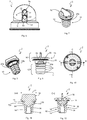
- FIG. 1 to 19 two exemplary embodiments of a measuring point system of the exhaust gas system 1 according to the invention are shown, the Figures 1 to 6 to a first embodiment and the Figures 13 to 15 refer to a second exemplary embodiment of the measuring point system 1.
- a closure element 2 is shown in various representations, which is identical for both exemplary embodiments of the measuring point system 1 and is used in both exemplary embodiments.
- the Figures 16 to 19 show the attachment of the closure element 2 to an external line component 3 of the measuring point system 1, which is also valid for both exemplary embodiments.
- the two exemplary embodiments of the measuring point system 1 of the exhaust system according to the invention differ only in the number of measuring points present, so that the following description applies to both exemplary embodiments.
- the measuring point system 1 of the exhaust system according to the invention has the external line component 3 and an internal line component 4 which is surrounded by the external line component 3.
- the inner line component 4 is partially surrounded by the outer line component 3, like the Figures 1 , 3 , 13 and 14 show for both embodiments. With these In embodiments, a pipe section of the inner line component 4 protrudes from the outer line component 3, it also being conceivable that the outer line component 3 completely surrounds the inner line component 4.
- the measuring point system 1 shown in the figures is intended for a boiler connection piece for exhaust systems, with concentric pipe bends in the exemplary embodiments shown.
- the invention is not limited to this application, but can also be used wherever measurements or sampling of two fluid flows are desired, which flow on the one hand through the inner line component 4 and on the other hand through the outer line component 3, the inner line component 4 and the External line component 3 define a double-walled line system.
- the measuring point system 1 of the first exemplary embodiment has two measuring points 5a and 5b, whereas in the second exemplary embodiment four measuring points 5 are provided (see FIG Figure 14 ).
- the measuring points 5a are provided for taking a sample of a fluid flowing through the inner line component 4
- the measuring point 5b is intended for taking a sample of a fluid which flows in the space formed between the outer line component 3 and the inner line component 4 .
- the measuring points 5a are used to measure the exhaust gas flowing for the inner line component 4 and the measuring points 5b are used to measure the supply air flowing between the inner line component 4 and the outer line component 3.
- a measuring connector 6 is provided, which extends from the outside of the inner line component 4 in the direction of the outer line component 3 and is formed at the end with an inner line component measuring opening 7 (see FIG Figure 2 or 16 ).
- the Inner line component measuring opening 7 establishes a connection to the interior 8 of the inner line component 4 via the measuring connector 6, so that, for example, a measuring probe used at the measuring point 5a can be guided via the measuring connector 6 into the interior 8 of the inner line component 4 for measurement.
- the measuring probe arrives at the measuring port 6 via an external line component opening 9 formed in the external line component 3.
- a further external line component measurement opening 9 is provided for measuring or taking samples of the fluid flowing between the external line component 3 and the internal line component 4, ie the supply air (see for example Figure 2 ).
- two measuring points 5a and 5b are provided for measuring exhaust gas and supply air, with the outer line component measuring openings 9 being identical for both measuring points 5a and 5b in both exemplary embodiments.
- the closure elements 2 for the measuring points 5a and 5b are also designed to be identical.
- a respective closure element 2 is detachably attached to the external line component 3 and closes the associated external line component measuring opening 9 in a sealing manner.
- a respective closure element 2 consequently seals the external line component measuring opening 9 assigned to it when it is inserted into the external line component measuring opening 9 and, if necessary, detachably fixed there, which will be discussed in more detail below.
- closure elements 2 like the external line component 3 and the internal line component 4, belong to the measuring point system 1 according to the two exemplary embodiments.
- a flange ring 29 serving for connection and a sealing ring 30 are shown.
- the measuring connector 6 extends in the direction of the external line component measuring opening 9 and has the end Inner line component measuring opening 7.
- a respective closure element 2 which is used universally for sealing both measuring points 5a and 5b, but in particular for sealing a respective measuring point 5a, has an elongated body 10. This is because when the closure element 2 is attached to the respective measuring point 5a of the external line component 3, this elongated body 10 extends, at least in sections, into the measuring connector 6. When attached, the closure element 2 seals off the entire measuring point 5a according to the invention. This means that the closure element 2 seals both the outer line component measuring opening 9 and the inner line component measuring opening 7, for example from the Figures 3, 4 , 14, 15 and 16 can be seen for both exemplary embodiments.
- the closure element 2 is shown in detail for various views in FIGS Figures 7 to 12 shown.
- a sealing section 12 is formed at a first longitudinal end 11 of the elongated body 10 of a respective closure element 2 (see, for example, FIG Figures 9, 11 or 12 ).
- the sealing section 12 is arranged within the measuring port 6, as is the case with FIGS Figures 3, 4 , 14, 15 and 16 demonstrate.
- the sealing section 12 has a total of four sealing lips 14, which are offset circumferentially around the elongated body 10 in the longitudinal direction of the elongated body 10. Alternatively, only a single sealing lip 14 could be formed on the elongated body 10.
- a respective closure element 2 has a head section 16 at a second longitudinal end 15 of the elongated body 10, which ensures simple manual handling of the closure element 2.
- the head section 16 has a larger cross section 17 compared to the elongated body 10.
- a sealing lip element 18 is integrally formed on the elongated body 10 of a respective closure element 2.
- the sealing lip element 18 is formed circumferentially around the elongated body 10 and is arranged between the sealing section 12 and the head section 16.
- the sealing lip element 18 is designed to be elastic and, when a respective closure element 2 is attached to the measuring points 5a and 5b, seals the respective external line component measuring opening 9.
- the Figures 11 and 12 show respective sectional views of the closure element, the sectional planes BB and CC from the top view Figure 10 emerge.
- a respective closure element 2 is secured with the aid of a locking mechanism 19 (see for example Figure 15 ) releasably fixable on the external line component 3. Accordingly, the closure element 2 for detachable fixation on the external line component 3 is out of an open position (see, for example Figure 19 ), in which a respective closure element 2 can be removed from the measuring points 5a, 5b and pulled out of the associated external line component measuring opening 9, into a locking position (see for example Figure 15 ) movable, in which a movement of the respective closure element 2 out of the associated external construction line component measuring opening 9 is blocked with the aid of the locking mechanism 19.
- the movement of the respective closure element 2 between the open position and the locking position is a rotary movement, with the closure element 2 for assembly in a Outer component line opening 9 is inserted and pulled out of this for dismantling.
- the locking mechanism 19 comprises two locking lugs 20a and 20b (see for example Figures 8, 11 and 15th ), which are formed on the elongated body 10 of a respective closure element 2.
- the two locking lugs 20a, 20b are formed diametrically to one another on the elongated body 10 and are arranged between the sealing lip element 18 and the sealing section 12 on the elongated body 10.
- only one locking projection is formed on the elongated body 10 of a respective closure element 2. This is because it is sufficient if only one of the locking lugs 20a, 20b engages behind the edge 21 of the associated external line component measuring opening 9 in the locking position of the respective closure element 2 (see, for example, FIG Figure 15 ).
- one of the two locking lugs 20b serves to noticeably indicate to an operator that the locking position has been reached.
- a stop region 23 is formed on a respective external line component measuring opening 9, against which one of the two locking lugs 20b rests in the locking position of a respective closure element 2, which is shown in FIG Figure 17 is shown, where in Figure 18 By omitting the closure element 2, the stop region 23 of the external line component measuring opening 9 can be seen.
- the respective external line component measuring openings 9 each have an enlarged area 22 (see, for example Figures 6 and 18th ), which is important for dismantling a respective closure element 2 or for taking samples.
- the two locking lugs 20a, 20b are arranged in alignment with the widened area of the respective external line component measuring opening 9, so that the Closure element 2 can be pulled out of the outer line component measuring opening 9.
- a gap 24 is formed between the inner line component measuring opening 7 and the outer line component 3 when a respective closure element 2 is inserted into an assigned outer line component measuring opening 9 of a measuring point 5a and the sealing section 12 of the elongated body 10 is sealingly arranged in the measuring port 6, as shown in FIGS Figures 4, 5 , 15th and 16 can be found. If the sealing section 12 can no longer fulfill its sealing function, the fluid flowing through the inner line component 4 does not flow into the external environment but into the outer line component 3, which significantly increases the safety of the measuring point system 1 compared to known systems.
- a respective measuring nozzle 6 ends at a predetermined distance 25 from the associated external line component measuring opening 9, although this is not absolutely necessary, because the measuring nozzle 6 could also end inside the external line component measuring opening 9 as long as the sealing lip element 18 seals the external line component measuring opening 9 and there is a gap 24 between the measuring connector 6 and the sealing lip element 18, through which the fluid flowing in the inner line component 4 can flow from the measuring connector 6 into the space between the outer line component 3 and the inner line component 4.
- a respective locking projection 20a, 20b has a holding surface 26 (see, for example, FIG Figures 9 and 19th ), which is arranged radially at the end on a respective locking projection 20a, 20b, and a respective external line component measuring opening 9 on the inside of the external line component 3, a blocking projection 27 (see FIG Figures 18 and 19 ) on.
- a respective locking projection 20a, 20b has a rising tightening surface 28 which is connected to the holding surface 26, which is designed to be sloping in relation to the rising tightening surface 28. Consequently, when the closure element 2 is rotated from the open position into the locking position, an operator has to exert increasing force in order to move the attraction surface 28 over the blocking projection 27.
- sealing section 12 can be designed with at least one sealing lip 14 in such a way that a sealing section 12 inserted through the external line component measuring opening 9 into the measuring connector 6 can be non-positively connected to the measuring stub 6 so that the holding force of the non-positive connection ensures the tightness of the measuring point system 1 without locking the closure element 2 being necessary for this.
Landscapes
- Engineering & Computer Science (AREA)
- Mechanical Engineering (AREA)
- General Engineering & Computer Science (AREA)
- Sampling And Sample Adjustment (AREA)
Description
Die Erfindung richtet sich auf eine Abgasanlage mit einem Kesselanschlussstück umfassend ein Messstellen-System mit einem Außenleitungsbauteil, welches wenigstens eine Außenleitungsbauteilmessöffnung aufweist, und einem Innenleitungsbauteil, welches von dem Außenleitungsbauteil wenigstens abschnittsweise umgeben ist und welches wenigstens einen außenseitig von dem Innenleitungsbauteil in Richtung der Außenleitungsbauteilmessöffnung erstreckenden und eine Verbindung zum Inneren des Innenleitungsbauteils herstellenden Messstutzen mit einer endseitig ausgebildeten Innenleitungsbauteilmessöffnung aufweist, wobei wenigstens ein Verschlusselement lösbar an dem Außenleitungsbauteil angebracht ist und die wenigstens eine Außenleitungsbauteilmessöffnung verschließend ausgebildet ist.The invention is directed to an exhaust system with a boiler connection piece comprising a measuring point system with an external line component which has at least one external line component measurement opening and an internal line component which is at least partially surrounded by the external line component and which extends at least one on the outside from the internal line component in the direction of the external line component measurement opening and has a connection to the inside of the inner line component producing measuring stub with an inner line component measuring opening formed at the end, at least one closure element being detachably attached to the outer line component and the at least one outer line component measuring opening being designed to close.
Für den Luft-Abgas-Betrieb von modernen Wärmeerzeugern, insbesondere von Brennwert- oder Niedertemperaturgeräten, werden zunehmend doppelwandige Leitungssysteme bzw. Rohrleitungssysteme eingesetzt, um einerseits das bei der Verbrennung entstehende Abgas sicher abzuführen und andererseits die zur Verbrennung benötigte Zuluft durch eine platzsparende Leitungsführung zuzuführen, wobei bei der Zuführung die Zuluft energieeinsparend von dem abgeführten Abgas vorerwärmt wird. Solche bekannten Leitungssysteme bestehen aus einem Außenleitungsbauteil und einem konzentrisch von dem Außenleitungsbauteil umgebenen Innenleitungsbauteil, wobei die Leitungsbauteile im Querschnitt kreisförmige Rohrleitungen sein können. Zur Abgas-Messung oder für eine Probe-Entnahme des Abgases steht bei solchen Leitungssystemen eine von außen zugängliche Messstelle zur Verfügung.For the air-exhaust operation of modern heat generators, in particular of condensing or low-temperature devices, double-walled pipe systems or pipe systems are increasingly being used, on the one hand to safely discharge the exhaust gas produced during combustion and, on the other hand, to supply the supply air required for combustion through a space-saving pipe system, with the supply air being preheated by the exhaust gas to save energy. Such known line systems consist of an outer line component and an inner line component surrounded concentrically by the outer line component, wherein the line components can be pipelines with a circular cross section. For exhaust gas measurement or for taking a sample of the exhaust gas, such An externally accessible measuring point is available to the pipeline systems.
Aus der
Ein Kesselanschlussstück zum Anschluss von Heizkesseln mit einem Messstellen-System der eingangs genannten Art ist beispielsweise aus der
Bei diesem bekannten Messstellen-System ist es von großem Nachteil, wenn der Stopfen für das Rohrstück undicht wird, denn dann tritt Abgas in den Aufstellraum der Abgasanlage aus, was zu einer für Personen gefährlichen Abgaskonzentration im Aufstellraum führt.In this known measuring point system, it is a great disadvantage if the plug for the pipe section leaks, because exhaust gas then escapes into the installation room of the exhaust system, which leads to an exhaust gas concentration in the installation room that is dangerous for people.
Der Erfindung liegt die Aufgabe zugrunde eine Lösung zu schaffen, die auf konstruktiv einfache Weise eine Abgasanlage mit einem Kesselanschlussstück umfassend ein Messstellen-System bereitstellt, das kostengünstig in seiner Herstellung ist und das darüber hinaus eine verbesserte Sicherheit im Fall einer Undichtigkeit des Stopfens bzw. Verschlusses garantiert, der eine Öffnung eines Messstutzens eines von einem Außenleitungsbauteil umgebenen Innenleitungsbauteil verschließt.The invention is based on the object of creating a solution which, in a structurally simple manner, comprises an exhaust system with a boiler connection piece comprising a measuring point system which is inexpensive to manufacture and which also guarantees improved safety in the event of a leak in the plug or closure which closes an opening of a measuring port of an inner line component surrounded by an external line component.
Bei einer Abgasanlage mit einem Kesselanschlussstück umfassend ein Messstellen-System der eingangs genannten Art wird die Aufgabe dadurch gelöst, dass ein Spalt zwischen der Innenleitungsbauteilmessöffnung und dem Außenleitungsbauteil ausgebildet ist, wobei das wenigstens eine Verschlusselement einen langgestreckten Körper aufweist, der sich bei Anbringung des wenigstens einen Verschlusselements an dem Außenleitungsbauteil zumindest abschnittsweise bis in den wenigstens einen Messstutzen hinein erstreckt und der sowohl die wenigstens eine Außenleitungsbauteilmessöffnung als auch die wenigstens eine Innenleitungsbauteilmessöffnung abdichtend ausgebildet ist. Im Sinne der Erfindung sind für eine Anordnung von Außenleitungsbauteil und Innenleitungsbauteil Anordnungen zu verstehen, bei denen entweder eckige Kanäle oder Rohre mit kreisförmigem Querschnitt beispielsweise konzentrisch zueinander angeordnet sind.In the case of an exhaust system with a boiler connection piece comprising a measuring point system of the type mentioned at the beginning, the object is achieved in that a gap is formed between the inner line component measuring opening and the outer line component, the at least one closure element having an elongated body which, when the at least one is attached Closure element on the outer line component extends at least in sections into the at least one measuring port and which both the at least one outer line component measuring opening and the at least one inner line component measuring opening is designed to be sealing. In the context of the invention, an arrangement of the outer line component and the inner line component is to be understood as meaning arrangements in which either angular channels or pipes with a circular cross section are arranged concentrically to one another, for example.
Vorteilhafte und zweckmäßige Ausgestaltungen und Weiterbildungen der Erfindung ergeben sich aus den Unteransprüchen.Advantageous and expedient refinements and developments of the invention emerge from the subclaims.
Durch die Erfindung wird eine Abgasanlage mit einem Kesselanschlussstück umfassend ein Messstellen-System zur Verfügung gestellt, das sich durch eine funktionsgerechte Konstruktion auszeichnet und einen kompakten sowie kostengünstigen Aufbau aufweist. Bei dem Messstellen-System der Abgasanlage gemäß der Erfindung wird eine doppelte Sicherheit hinsichtlich der Dichtigkeit erreicht. Denn sollte der Bereich des langgestreckten Körpers, welcher sich bei Anbringung des Verschlusselements an dem Außenleitungsbauteil zumindest abschnittsweise bin in den Messstutzen hinein erstreckt und die Innenleitungsbauteilmessöffnung abdichten soll, undicht werden, kann beispielsweise ein durch das Innenleitungsbauteil strömendes Abgas nur in das Außenleitungsbauteil strömen, aber niemals aus dem Außen-leitungsbauteil in die äußere Umgebung, wie zum Beispiel ein geschlossener Aufstellraum für eine Abgasanlage, denn das Verschlusselement stellt eine doppelte Sicherheit durch die Abdichtung sowohl der Außenleitungsbauteilmessöffnung als auch der Innenleitungsbauteilmessöffnung dar. Kommt es tatsächlich zu einer Undichtigkeit an der Innenleitungsbauteilmessöffnung, so dass Abgas in das Außenleitungsbauteil strömt, wird die Abgasanlage aufgrund der mit Abgas beladenen Zuluft eine Störmeldung anzeigen, wobei es aber zu keinem Austritt von Abgas in den Aufstellraum kommt. Vielmehr kann infolge der Störmeldung die Dichtigkeit der Innenleitungsbauteilmessöffnung überprüft und wiederhergestellt werden, ohne dass es zu einer für Personen gefährlichen Situation durch eine erhöhte Abgaskonzentration im Aufstellraum kommt.The invention provides an exhaust system with a boiler connection piece comprising a measuring point system which is characterized by a functionally appropriate construction and has a compact and cost-effective structure. With the measuring point system of the exhaust system according to the invention, a double security with regard to the tightness is achieved. This is because if the area of the elongated body which, when the closure element is attached to the external line component, extends at least in sections into the measuring nozzle and is intended to seal the internal line component measuring opening, should leak, For example, an exhaust gas flowing through the inner line component can only flow into the outer line component, but never from the outer line component into the external environment, such as a closed installation room for an exhaust system, because the closure element provides double security by sealing both the outer line component measurement opening and the If there is actually a leak at the inner line component measuring opening, so that exhaust gas flows into the outer line component, the exhaust system will display a fault message due to the supply air laden with exhaust gas, but there will be no exhaust gas escaping into the installation room. Rather, as a result of the fault message, the tightness of the inner line component measuring opening can be checked and restored without a situation that is dangerous for people due to an increased exhaust gas concentration in the installation room.
Die Erfindung sieht in Ausgestaltung vor, dass der wenigstens eine Messstutzen in einem vorgegebenen Abstand zu der wenigstens einen Außenleitungsbauteilmessöffnung endet. Trotz vorhandenem Spalt zwischen der Innenleitungsbauteilmessöffnung und dem Außenleitungsbauteil und könnte sich der Messstutzen bis in die Außenleitungsbauteilmessöffnung erstrecken - jedoch ist durch die Ausgestaltung, dass der Messstutzen in einem vorgegebenen Abstand zur Außenleitungsbauteilmessöffnung endet, in jedem Fall sichergestellt, dass ein ausreichender Spalt vorhanden ist, durch den im Fall einer Undichtigkeit der Innenleitungsbauteilmessöffnung das durch das Innenleitungsbauteil strömende Fluid, wie zum Beispiel Abgas, in das Außenleitungsbauteil strömt.In one embodiment, the invention provides that the at least one measuring port ends at a predetermined distance from the at least one external line component measuring opening. Despite the existing gap between the inner line component measuring opening and the outer line component, the measuring nozzle could extend into the outer line component measuring opening - however, the design so that the measuring nozzle ends at a predetermined distance from the outer line component measuring opening ensures that there is a sufficient gap in every case that in the event of a leak in the inner line component measuring opening through the inner line component flowing fluid, such as exhaust gas, flows into the outer conduit component.
Zur Erhöhung der Dichtwirkung an der Innenleitungsbauteilmessöffnung sieht die Erfindung in weiterer Ausgestaltung vor, dass an einem ersten Längsende des langgestreckten Körpers des wenigstens einen Verschlusselements ein Dichtungsabschnitt ausgebildet ist, der bei Anbringung des wenigstens einen Verschlusselements an dem Außenleitungsbauteil innerhalb des wenigstens einen Messstutzens angeordnet ist und an dem wenigstens eine um den langgestreckten Körper umlaufende und von diesem abstehende Dichtlippe angeformt ist, die elastisch verformbar ausgebildet ist. Es können auch mehr als eine Dichtlippe an dem langgestreckten Körper ausgebildet sein, wobei der langgestreckte Körper mit dem Abschnitt mit der wenigstens einen Dichtlippe die Innenleitungsbauteilmessöffnung abdichtend in den Messstutzen eingedrückt ist. Der langgestreckte Körper des wenigstens einen Verschlusselements muss folglich nicht sehr genau an den Querschnitt des Messstutzens angepasst sein, so dass der langgestreckte Körper mit großzügigen Toleranzen hergestellt werden kann, denn die wenigstens eine Dichtlippe sorgt für die Dichtwirkung. Folglich weist der langgestreckte Körper mitsamt der wenigstens einen Dichtlippe einen größeren Querschnitt als der Messstutzen auf.To increase the sealing effect on the inner line component measuring opening, the invention provides in a further embodiment that a sealing section is formed on a first longitudinal end of the elongated body of the at least one closure element, which is arranged within the at least one measuring connector when the at least one closure element is attached to the outer line component and on which at least one sealing lip which extends around the elongate body and protrudes therefrom is integrally formed and which is designed to be elastically deformable. It is also possible for more than one sealing lip to be formed on the elongated body, the elongated body with the section with the at least one sealing lip being pressed into the measuring nozzle in a sealing manner. The elongated body of the at least one closure element therefore does not have to be adapted very precisely to the cross section of the measuring port, so that the elongated body can be produced with generous tolerances, because the at least one sealing lip ensures the sealing effect. As a result, the elongated body together with the at least one sealing lip has a larger cross section than the measuring nozzle.
Zur einfachen Montage und Demontage des Verschlusselements sieht die Erfindung in Ausgestaltung vor, dass an einem zweiten Längsende des langgestreckten Körpers des wenigstens einen Verschlusselements ein im Vergleich zum langgestreckten Körper einen größeren Querschnitt aufweisender Kopfabschnitt zur Handhabung des wenigstens einen Verschlusselements ausgebildet ist. Das Verschlusselement, welches zur Anbringung an dem Außenleitungsbauteil nach Art einer Schraube festgedreht werden muss, kann bei entsprechender Ausbildung des Kopfabschnitts entweder per Hand oder mit Hilfe einer Münze oder eines Inbusschlüssels gedreht werden.For easy assembly and disassembly of the closure element, the invention provides in an embodiment that a head section for handling the at least one closure element is formed at a second longitudinal end of the elongated body of the at least one closure element, which has a larger cross-section than the elongated body. The closure element, which has to be tightened like a screw for attachment to the external line component, can be turned either by hand or with the aid of a coin or an Allen key if the head section is designed accordingly.
Zur Abdichtung der Außenleitungsbauteilmessöffnung ist es von Vorteil, wenn an dem langgestreckten Körper des wenigstens einen Verschlusselements zwischen dem Dichtungsabschnitt und dem Kopfabschnitt wenigstens ein um den langgestreckten Körper umlaufendes und elastisch ausgebildetes Dichtlippenelement angeformt ist, welches bei Anbringung des wenigstens einen Verschlusselements an dem Außenleitungsbauteil auf der Außenseite des Außenleitungsbauteils die wenigstens eine Außenleitungsbauteilmessöffnung dichtend verschließt. Das Dichtlippenelement dichtet folglich den Bereich zwischen dem langgestreckten Körper des wenigstens einen Verschlusselements und der Außenleitungsbauteilöffnung ab.To seal the outer line component measuring opening, it is advantageous if at least one sealing lip element is formed on the elongated body of the at least one closure element between the sealing section and the head section, which encircles the elongated body and is elastically formed, which when the at least one closure element is attached to the outer line component on the Outside of the external line component which seals off at least one external line component measuring opening. The sealing lip element consequently seals off the area between the elongated body of the at least one closure element and the outer line component opening.
Die Erfindung sieht in weiterer Ausgestaltung vor, dass das wenigstens eine Verschlusselement mit Hilfe eines Verriegelungsmechanismus lösbar an dem Außenleitungsbauteil fixierbar ist, wobei zur lösbaren Fixierung des wenigstens einen Verschlusselements an dem Außenleitungsbauteil das wenigstens eine Verschlusselement aus einer Öffnungsstellung, in welcher das Verschlusselement aus der wenigstens einen Außenleitungsbauteilmessöffnung herausziehbar ist, in eine Verriegelungsstellung, in welcher eine Bewegung des wenigstens einen Verschlusselements aus der wenigstens einen Außenbauleitungsbauteilmessöffnung mit Hilfe des Verriegelungsmechanismus blockiert ist, drehbar ist. Gemäß der Weiterbildung existieren definierte Positionen für das Verschlusselement, so dass bei einer entsprechend angebrachten Markierung in einem Bereich des Verschlusselements, der von außen sichtbar ist, sofort erkannt werden kann, ob sich das Verschlusselement in einer verriegelten und gesicherten Position zur Abdichtung des Systems befindet.In a further embodiment, the invention provides that the at least one closure element can be releasably fixed to the external line component with the aid of a locking mechanism, with the at least one closure element from an open position in which the closure element from the at least an external line component measuring opening can be pulled out into a locking position in which a movement of the at least one closure element out of the at least one external line component measuring opening is blocked with the aid of the locking mechanism. According to the development, there are defined positions for the closure element, so that when a corresponding marking is applied in an area of the closure element that is visible from the outside, it can be recognized immediately whether the closure element is in a locked and secured position for sealing the system.
Eine konstruktiv einfache Möglichkeit für eine sichere Verriegelung und damit Abdichtung ist in Ausgestaltung der Erfindung dadurch realisierbar, dass der Verriegelungsmechanismus wenigstens einen Verriegelungsansatz umfasst, der an dem langgestreckten Körper des wenigstens einen Verschlusselements ausgebildet ist, wobei der wenigstens eine Verriegelungsansatz in Verriegelungsstellung des wenigstens einen Verschlusselements den Rand der wenigstens einen Außenleitungsbauteilmessöffnung hintergreifend angeordnet ist, wohingegen der wenigstens eine Verriegelungsansatz in Öffnungsstellung des wenigstens einen Verschlusselements fluchtend zu einem erweiterten Bereich der wenigstens einen Außenleitungsbauteilmessöffnung angeordnet ist. Dabei kann das Verschlusselement nur in der Öffnungsstellung aus der Außenleitungsbauteilmessöffnung des Außenleitungsbauteils herausgezogen werden, was die Verlierbarkeit des Verschlusselements bei Demontage zu Messzwecken verringert.A structurally simple possibility for secure locking and thus sealing can be implemented in an embodiment of the invention in that the locking mechanism has at least one locking attachment which is formed on the elongated body of the at least one closure element, the at least one locking projection in the locking position of the at least one closure element being arranged to reach behind the edge of the at least one external line component measuring opening, whereas the at least one locking projection in the opening position of the at least one closure element is in alignment with an enlarged one Area of the at least one external line component measuring opening is arranged. In this case, the closure element can only be pulled out of the external line component measurement opening of the external line component in the open position, which reduces the loss of the closure element when it is dismantled for measurement purposes.
Zur sicheren Fixierung des Verschlusselements, damit dieses bei Vibrationen nicht aus seiner Verriegelungsstellung zurück in die Öffnungsstellung gelangt, ist in Ausgestaltung der Erfindung vorgesehen, dass der wenigstens eine Verriegelungsansatz des wenigstens einen Verschlusselements eine ansteigende Anzugfläche und eine sich an die ansteigende Anzugfläche anschließende, abfallende Haltefläche aufweist und dass an der wenigstens einen Außenleitungsbauteilmessöffnung innenseitig des Außenleitungsbauteils ein Blockierungsansatz ausgebildet ist, wobei in Verriegelungsstellung des wenigstens einen Verschlusselements die abfallende Haltefläche an dem Blockierungsansatz anliegt und der Blockierungsansatz eine Bewegung des wenigstens einen Verschlusselements in Richtung der Öffnungsstellung blockiert.To securely fix the closure element so that it does not move from its locking position back into the open position in the event of vibrations, an embodiment of the invention provides that the at least one locking attachment of the at least one closure element has a rising tightening surface and a sloping holding surface that adjoins the rising tightening surface and that a blocking attachment is formed on the at least one external line component measuring opening on the inside of the external line component, wherein in the locking position of the at least one closure element the sloping holding surface rests against the blocking attachment and the blocking attachment blocks a movement of the at least one closure element in the direction of the opening position.
Damit für den Bediener eine Bewegung des Verschlusselements aus der Öffnungsstellung in die Verriegelungsstellung spürbar ist, sieht die Erfindung in weiterer Ausgestaltung vor, dass zur Fixierung des wenigstens einen Verschlusselements an dem Außenleitungsbauteil bei Bewegung des wenigstens einen Verschlusselements aus der Öffnungsstellung in die Verriegelungsstellung sich die ansteigende Anzugfläche über den Blockierungsansatz hinweg bewegt und der Blockierungsansatz dabei das wenigstens eine Verschlusselement in Richtung des Innenleitungsbauteils drängt. Folglich muss eine erhöhte Kraft aufgewandt werden, um das Verschlusselement aus der Öffnungsstellung in die Verriegelungsstellung zu bewegen. Darüber hinaus sorgt die ansteigende Anzugfläche dafür, dass das Verschlusselement in Richtung des Innenleitungsbauteils bewegt wird, wodurch die Dichtwirkung erhöht wird.In order that a movement of the closure element from the open position into the locking position can be felt by the operator, the invention provides in a further embodiment that, in order to fix the at least one closure element on the external line component, when the at least one closure element is moved from the open position into the locking position, the increasing Suit area over the Blocking approach moved away and the blocking approach thereby pushes the at least one closure element in the direction of the inner line component. Consequently, an increased force has to be applied in order to move the closure element from the open position into the locking position. In addition, the rising tightening surface ensures that the closure element is moved in the direction of the inner line component, whereby the sealing effect is increased.
Die Erfindung sieht in weiterer Ausgestaltung vor, dass an dem langgestreckten Körper des wenigstens einen Verschlusselements zwei Verriegelungsansätze ausgebildet sind, die diametral zueinander an dem langgestreckten Körper angeformt sind. Dabei kann auch der zweite Verriegelungsansatz in Verriegelungsstellung des Verschlusselements den Rand der wenigstens einen Außenleitungsbauteilmessöffnung hintergreifen, so dass das Verschlusselement sehr sicher mittels einer formschlüssigen Verbindung an einer Bewegung von dem Messstutzen weg gesichert ist.In a further embodiment, the invention provides that two locking lugs are formed on the elongated body of the at least one closure element, which are formed diametrically to one another on the elongated body. The second locking projection can also engage behind the edge of the at least one external line component measurement opening in the locking position of the closure element, so that the closure element is secured very securely by means of a form-fitting connection to move away from the measurement port.
Schließlich sieht die Erfindung in weiterer Ausgestaltung vor, dass an der wenigstens einen Außenleitungsbauteilmessöffnung ein Anschlagbereich ausgebildet ist, an welchem einer der beiden Verriegelungsansätze in Verriegelungsstellung des wenigstens einen Verschlusselements anliegt. Auf diese Weise ist die Endlage des Verschlusselements in der Verriegelungsstellung definiert und damit gewährleistet, dass das Verschlusselement auch tatsächlich in seiner Verriegelungsstellung positioniert ist und nicht in einer darüber hinausliegenden Position.Finally, in a further embodiment, the invention provides that a stop area is formed on the at least one external line component measuring opening, against which one of the two locking lugs rests in the locking position of the at least one closure element. In this way, the end position of the closure element is defined in the locking position, thus ensuring that the closure element is actually positioned in its locking position and not in a position beyond it.
Es versteht sich, dass die vorstehend genannten und nachstehend noch zu erläuternden Merkmale nicht nur in der jeweils angegebenen Kombination, sondern auch in anderen Kombinationen oder in Alleinstellung verwendbar sind, ohne den Rahmen der vorliegenden Erfindung zu verlassen. Der Rahmen der Erfindung ist nur durch die Ansprüche definiert.It goes without saying that the features mentioned above and still to be explained below can be used not only in the respectively specified combination, but also in other combinations or on their own, without departing from the scope of the present invention. The scope of the invention is defined only by the claims.
Weitere Einzelheiten, Merkmale und Vorteile des Gegenstandes der Erfindung ergeben sich aus der nachfolgenden Beschreibung im Zusammenhang mit der Zeichnung, in der beispielhafte bevorzugte Ausführungsbeispiele der Erfindung dargestellt sind. In der Zeichnung zeigt:
-
Figur 1 -
Figur 2Figur 1 -
Figur 3Figur 1 -
Figur 4Figur 3 -
Figur 5 eine wie inFigur 4 -
Figur 6Figur 1 -
Figur 7 -
Figur 8Figur 7 -
Figur 9Figur 7 -
Figur 10Figur 7 -
Figur 11Figur 7 -
Figur 12Figur 7Figur 11 -
Figur 13 das Messstellen-System der erfindungsgemäßen Abgasanlage gemäß einem zweiten Ausführungsbeispiel, -
Figur 14Figur 13 , -
Figur 15 -
Figur 16 -
Figur 17 -
Figur 18 -
Figur 19
-
Figure 1 a measuring point system of the exhaust system according to the invention according to a first embodiment, -
Figure 2 a perspective view of individual parts of the measuring point systemFigure 1 , -
Figure 3 a side sectional view of the measuring point systemFigure 1 , -
Figure 4 an enlarged detailed viewFigure 3 , -
Figure 5 one like inFigure 4 The illustration shown, in which the closure elements are not shown, -
Figure 6 a rear view of the measuring point systemFigure 1 , whereby here, too, closure elements are not shown, -
Figure 7 a perspective view of a closure element, -
Figure 8 a further perspective view of the closure elementFigure 7 , -
Figure 9 a side view of the inFigure 7 shown closure element, -
Figure 10 a top view of the inFigure 7 shown closure element, -
Figure 11 a side sectional view of the inFigure 7 shown closure element, -
Figure 12 a further sectional side view of the inFigure 7 shown closure element, where it is compared toFigure 11 is a cut rotated by 90 °, -
Figure 13 the measuring point system of the exhaust system according to the invention according to a second embodiment, -
Figure 14 a perspective sectional view of the measuring point systemFigure 13 , -
Figure 15 a detailed sectional view of two measuring points of the measuring point system of the exhaust system according to the invention, -
Figure 16 a further detailed sectional view of a measuring point of the measuring point system of the exhaust system according to the invention, -
Figure 17 another detailed view of a measuring point of the measuring point system, -
Figure 18 a view of an external line component measuring opening of the measuring point system, and -
Figure 19 a detailed view of a closure element in the open position.
In den
Die beiden Ausführungsbeispiele des Messstellen-Systems 1 der erfindungsgemäßen Abgasanlage unterscheiden sich lediglich durch die Anzahl der vorhandenen Messstellen, so dass die nachstehende Beschreibung für beide Ausführungsbeispiele gilt.The two exemplary embodiments of the
Das Messstellen-System 1 der erfindungsgemäßen Abgasanlage weist das Außenleitungsbauteil 3 und ein Innenleitungsbauteil 4 auf, welches von dem Außenleitungsbauteil 3 umgeben ist. Dabei ist das Innenleitungsbauteil 4 abschnittsweise von dem Außenleitungsbauteil 3 umgeben, wie die
Wie der Vergleich der
Zur Messung oder Probenentnahme des durch das Innenleitungsbauteil 4 strömenden Fluids bzw. Abgases ist ein Messstutzen 6 vorgesehen, der sich von der Außenseite des Innenleitungsbauteils 4 aus in Richtung des Außenleitungsbauteils 3 erstreckt und endseitig mit einer Innenleitungsbauteilmessöffnung 7 ausgebildet ist (siehe
Im Unterschied zu dem ersten Ausführungsbeispiel sind bei dem zweiten Ausführungsbeispiel folglich jeweils zwei Messstellen 5a und 5b für eine Abgas- und eine Zuluft-Messung vorgesehen, wobei bei beiden Ausführungsbeispielen die Außenleitungsbauteilmessöffnungen 9 für beide Messstellen 5a und 5b identisch ausgebildet sind. Bei beiden in den Figuren gezeigten Ausführungsbeispielen sind auch die Verschlusselemente 2 für die Messstellen 5a und 5b baugleich ausgebildet. Dabei ist ein jeweiliges Verschlusselement 2 lösbar an dem Außenleitungsbauteil 3 angebracht und verschließt die zugeordnete Außenleitungsbauteilmessöffnung 9 in dichtender Weise. Ein jeweiliges Verschlusselement 2 dichtet folglich die ihm zugeordnete Außenleitungsbauteilmessöffnung 9 ab, wenn es in die Außenleitungsbauteilmessöffnung 9 eingesteckt und ggf. dort lösbar fixiert ist, worauf nachstehend noch näher eingegangen wird. Es versteht sich, dass die Verschlusselemente 2 ebenso wie das Außenleitungsbauteil 3 sowie das Innenleitungsbauteil 4 zu dem Messstellen-System 1 gemäß den beiden Ausführungsbeispielen gehören. Der Vollständigkeit halber sei erwähnt, dass in
Der Messstutzen 6 erstreckt sich in Richtung der Außenleitungsbauteilmessöffnung 9 und weist endseitig die Innenleitungsbauteilmessöffnung 7 auf. Ein jeweiliges Verschlusselement 2, welches universell zur Abdichtung beider Messstellen 5a und 5b, aber insbesondere zur Abdichtung einer jeweiligen Messstelle 5a verwendet wird, weist einen langgestreckten Körper 10 auf. Denn dieser langgestreckte Körper 10 erstreckt sich bei Anbringung des Verschlusselements 2 an der jeweiligen Messstelle 5a des Außenleitungsbauteils 3 zumindest abschnittsweise bis in den Messstutzen 6 hinein. Bei Anbringung dichtet das Verschlusselement 2 erfindungsgemäß die gesamte Messstelle 5a ab. Dies bedeutet, dass das Verschlusselement 2 sowohl die Außenleitungsbauteilmessöffnung 9 als auch die Innenleitungsbauteilmessöffnung 7 abdichtet, wie beispielsweise aus den
Ein jeweiliges Verschlusselement 2 ist mit Hilfe eines Verriegelungsmechanismus 19 (siehe zum Beispiel
Der Verriegelungsmechanismus 19 umfasst zwei Verriegelungsansätze 20a und 20b (siehe zum Beispiel
Erfindungsgemäß ist zwischen der Innenleitungsbauteilmessöffnung 7 und dem Außenleitungsbauteil 3 ein Spalt 24 ausgebildet, wenn ein jeweiliges Verschlusselement 2 in eine zugeordnete Außenleitungsbauteilmessöffnung 9 einer Messstelle 5a eingesteckt ist und der Dichtungsabschnitt 12 des langgestreckten Körpers 10 in dem Messstutzen 6 abdichtend angeordnet ist, wie aus den
Damit ein jeweiliges Verschlusselement 2 in seiner Verriegelungsstellung angeordnet verbleibt, weist ein jeweiliger Verriegelungsansatz 20a, 20b eine Haltefläche 26 (siehe zum Beispiel
Es sei angemerkt, dass der Dichtungsabschnitt 12 mit wenigstens einer Dichtlippe 14 so ausgebildet sein kann, dass ein durch die Außenleitungsbauteilmessöffnung 9 in den Messstutzen 6 eingesteckter Dichtungsabschnitt 12 derart kraftschlüssig mit dem Messstutzen 6 verbunden sein kann, dass die Haltekraft der kraftschlüssigen Verbindung die Dichtheit des Messstellen-Systems 1 gewährleistet, ohne dass dazu eine Verriegelung des Verschlusselements 2 notwendig ist.It should be noted that the sealing
Die vorstehend beschriebene Erfindung ist selbstverständlich nicht auf die beschriebenen und dargestellten Ausführungsformen beschränkt. Es ist ersichtlich, dass an den in der Zeichnung dargestellten Ausführungsformen zahlreiche, dem Fachmann entsprechend der beabsichtigten Anwendung naheliegende Abänderungen vorgenommen werden können, ohne dass dadurch der Bereich der Erfindung verlassen wird. Zur Erfindung gehört alles dasjenige, was in der Beschreibung enthalten und/oder in der Zeichnung dargestellt ist, einschließlich dessen, was abweichend von den konkreten Ausführungsbeispielen für den Fachmann naheliegt.The invention described above is of course not restricted to the embodiments described and illustrated. It is evident that numerous modifications, which are obvious to a person skilled in the art according to the intended application, can be made to the embodiments shown in the drawing, without thereby departing from the scope of the invention. The invention includes everything that is contained in the description and / or shown in the drawing, including that which deviates from the specific exemplary embodiments and is obvious to the person skilled in the art.
Claims (11)
- An exhaust gas system with a boiler connection piece comprising a measurement site system (1) with• an external line component (3), which has at least one external line component measurement opening (9), and• an internal line component (4), which is at least partially surrounded by the external line component (3) and which has at least one measurement connection (6) extending externally from the internal line component (4) in the direction of the external line component measurement opening (9) and producing a connection to the interior (8) of the internal line component (4), with an internal line component measurement opening (7) formed on the end side,wherein at least one closure element (2) is detachably mounted on the external line component (3) and is configured closing the at least one external line component measurement opening (8),
characterized in that
a gap (24) is formed between the internal line component measurement opening (7) and the external line component (3), wherein the at least one closure element (2) has an elongated body (10) which, on mounting of the at least one closure element (2) on the external line component (3), extends at least partially to into the at least one measurement connection (6) and which is configured sealing both the at least one eternal line component measurement opening (9) and also the at least one internal line component measurement opening (7). - The exhaust gas system according to Claim 1, characterized in that the at least one measurement connection (6) ends at a predetermined distance (25) from the at least one external line component measurement opening (9).
- The exhaust gas system according to Claim 1 or 2, characterized in that at a first longitudinal end (11) of the elongated body (10) of the at least one closure element (2) a sealing portion (12) is formed which, on mounting of the at least one closure element (2) on the external line component (3), is arranged within the at least one measurement connection (6), and on which at least one sealing lip (14) is formed, running around the elongated body (10) and protruding therefrom, which sealing lip is formed in an elastically deformable manner.
- The exhaust gas system according to Claim 3, characterized in that at a second longitudinal end (16) of the elongated body (10) of the at least one closure element (2), a head portion (16), having a greater cross-section (17) compared to the elongated body (10), is formed for the handling of the at least one closure element (2).
- The exhaust gas system according to Claim 4, characterized in that on the elongated body (10) of the at least one closure element (2) between the sealing portion (12) and the head portion (16) at least one sealing lip element (18) is formed, running around the elongated body (10) and formed in an elastic manner which, on mounting of the at least one closure element (2) on the external line component (3) on the outer side of the external line component (3) closes the at least one external line component measurement opening (9) in a sealing manner.
- The exhaust gas system according to one of the preceding claims, characterized in that the at least one closure element (2) is able to be fixed detachably on the external line component (3) by means of a locking mechanism (19), wherein for the detachable fixing of the at least one closure element (2) on the external line component (3), the at least one closure element (2) is able to be rotated from an opening position, in which the closure element (2) is able to be withdrawn from the at least one external line component measurement opening (9), into a locking position, in which a movement of the at least one closure element (2) out of the at least one external component line component measurement opening (9) is blocked by means of the locking mechanism (19).
- The exhaust gas system according to Claim 6, characterized in that the locking mechanism (19) comprises at least one locking lug (20a, 20b), which is formed on the elongated body (10) of the at least one closure element (2), wherein the at least one locking lug (20a, 20b) in locking position of the at least one closure element (2) is arranged engaging behind the edge (21) of the at least one external line component measurement opening (9), whereas the at least one locking lug (20a, 20b) in opening position of the at least one closure element (2) is arranged in alignment with a widened region (22) of the at least one external line component measurement opening (9).
- The exhaust gas system according to Claim 7, characterized in that the at least one locking lug (20a, 20b) of the at least one closure element (2) has an ascending approach surface (28) and a descending holding surface (26), adjoining the ascending approach surface (28), and that at the at least one external line component measurement opening (9) on the inner side of the external line component (3) a blocking lug (27) is formed, wherein in locking position of the at least one closure element (2) the descending holding surface (26) lies against the blocking lug (27), and the blocking lug (27) blocks a movement of the at least one closure element (2) in the direction of the opening position.
- The exhaust gas system according to Claim 8, characterized in that for fixing the at least one closure element (2) on the external line component (3) on movement of the at least one closure element (2) from the opening position into the locking position, the ascending approach surface (28) moves over the blocking lug (27), and the blocking lug (27) in doing so urges the at least one closure element (2) in the direction of the internal line component (4).
- The exhaust gas system according to one of Claims 7 to 9, characterized in that on the elongated body (10) of the at least one closure element (2), two locking lugs (20a, 20b) are formed, which are formed diametrically with respect to one another on the elongated body (10).
- The exhaust gas system according to Claim 10, characterized in that at the at least one external ling component measurement opening (9) a stop region (23) is formed, against which one of the two locking lugs (20a, 20b) lies in locking position of the at least one closure element (2) .
Priority Applications (2)
| Application Number | Priority Date | Filing Date | Title |
|---|---|---|---|
| EP17167807.1A EP3396246B1 (en) | 2017-04-24 | 2017-04-24 | Exhaust gas system with measurement site system |
| ES17167807T ES2901987T3 (en) | 2017-04-24 | 2017-04-24 | Exhaust gas evacuation device with measuring point system |
Applications Claiming Priority (1)
| Application Number | Priority Date | Filing Date | Title |
|---|---|---|---|
| EP17167807.1A EP3396246B1 (en) | 2017-04-24 | 2017-04-24 | Exhaust gas system with measurement site system |
Publications (2)
| Publication Number | Publication Date |
|---|---|
| EP3396246A1 EP3396246A1 (en) | 2018-10-31 |
| EP3396246B1 true EP3396246B1 (en) | 2021-11-24 |
Family
ID=58671382
Family Applications (1)
| Application Number | Title | Priority Date | Filing Date |
|---|---|---|---|
| EP17167807.1A Active EP3396246B1 (en) | 2017-04-24 | 2017-04-24 | Exhaust gas system with measurement site system |
Country Status (2)
| Country | Link |
|---|---|
| EP (1) | EP3396246B1 (en) |
| ES (1) | ES2901987T3 (en) |
Families Citing this family (2)
| Publication number | Priority date | Publication date | Assignee | Title |
|---|---|---|---|---|
| DE102019129758A1 (en) | 2019-11-05 | 2021-05-06 | Vaillant Gmbh | Heater with safe exhaust gas measurement opening |
| DE102021103715A1 (en) * | 2021-02-17 | 2022-08-18 | Vaillant Gmbh | Heating system with bayonet connection between heater and flue gas supply air pipe system |
Family Cites Families (3)
| Publication number | Priority date | Publication date | Assignee | Title |
|---|---|---|---|---|
| DE9419630U1 (en) * | 1994-12-09 | 1995-02-02 | Fresenius Ag | Device for closing a line |
| DE10053067C1 (en) | 2000-10-26 | 2002-06-13 | Skoberne Willi | Boiler connector for exhaust systems |
| CA2905829A1 (en) * | 2013-03-14 | 2014-10-02 | Excelsior Medical Corporation | Antiseptic dead-end cap |
-
2017
- 2017-04-24 ES ES17167807T patent/ES2901987T3/en active Active
- 2017-04-24 EP EP17167807.1A patent/EP3396246B1/en active Active
Also Published As
| Publication number | Publication date |
|---|---|
| EP3396246A1 (en) | 2018-10-31 |
| ES2901987T3 (en) | 2022-03-24 |
Similar Documents
| Publication | Publication Date | Title |
|---|---|---|
| EP1934405B1 (en) | Sanitary installation part | |
| DE3100037A1 (en) | TAP WITH LENS OR SPHERICAL CLOSURE LINK | |
| EP2000681B1 (en) | Support sleeve | |
| EP3396246B1 (en) | Exhaust gas system with measurement site system | |
| EP3441657A1 (en) | Conduit connection for piping with a leak indicator | |
| EP1601914B1 (en) | Ventilation valve for heaters, comprising a holding body and an axially displaceable valve body | |
| DE102005044751B4 (en) | Connectors for media cables | |
| DE19519073B4 (en) | Device for connecting pipe sections with each other | |
| EP1775507B1 (en) | Fitting for pipes | |
| DE102017119704B4 (en) | Line coupling and container herewith | |
| EP3312352B1 (en) | Insert with a water conveying cartridge housing | |
| WO2018178166A1 (en) | Connecting device for media lines | |
| DE1775765B2 (en) | Adhesive-free connection for pipes, in particular sewer pipes made of plastic | |
| EP3103932B1 (en) | Antiflooding valve | |
| DE102017129559B4 (en) | Connection head for a filter candle, set with a connection head and filter candle | |
| DE102014114486B4 (en) | Drain connection | |
| EP3775658A1 (en) | Connecting device for media lines | |
| DE202012104309U1 (en) | Device for use in the distribution of liquid and / or gaseous media | |
| DE4223251A1 (en) | Automatically mountable plug-in coupling for hose lines in motor vehicles | |
| DE202005004524U1 (en) | Plug-in connection for joining pipe to fitting, comprising clamping ring with additional projections on outer surface | |
| DE102005048965A1 (en) | Sanitary built-in part, e.g. for preventing return/back flow, has a built-in casing to be inserted with a means of locking into a casing retention device on a gas or liquid pipe | |
| DE10307921B3 (en) | Plug-fit connector for fluid, steam or air line has rotary locking device for securing inserted coupling plug in coupling housing | |
| DE202009014250U1 (en) | Plug-in coupling for connecting in particular plastic pipes | |
| DE102008051269A1 (en) | emptying device | |
| DE102008046836B4 (en) | Storage tank system with shut-off device |
Legal Events
| Date | Code | Title | Description |
|---|---|---|---|
| PUAI | Public reference made under article 153(3) epc to a published international application that has entered the european phase |
Free format text: ORIGINAL CODE: 0009012 |
|
| STAA | Information on the status of an ep patent application or granted ep patent |
Free format text: STATUS: THE APPLICATION HAS BEEN PUBLISHED |
|
| AK | Designated contracting states |
Kind code of ref document: A1 Designated state(s): AL AT BE BG CH CY CZ DE DK EE ES FI FR GB GR HR HU IE IS IT LI LT LU LV MC MK MT NL NO PL PT RO RS SE SI SK SM TR |
|
| AX | Request for extension of the european patent |
Extension state: BA ME |
|
| STAA | Information on the status of an ep patent application or granted ep patent |
Free format text: STATUS: REQUEST FOR EXAMINATION WAS MADE |
|
| 17P | Request for examination filed |
Effective date: 20190430 |
|
| RBV | Designated contracting states (corrected) |
Designated state(s): AL AT BE BG CH CY CZ DE DK EE ES FI FR GB GR HR HU IE IS IT LI LT LU LV MC MK MT NL NO PL PT RO RS SE SI SK SM TR |
|
| STAA | Information on the status of an ep patent application or granted ep patent |
Free format text: STATUS: EXAMINATION IS IN PROGRESS |
|
| STAA | Information on the status of an ep patent application or granted ep patent |
Free format text: STATUS: EXAMINATION IS IN PROGRESS |
|
| 17Q | First examination report despatched |
Effective date: 20201222 |
|
| GRAP | Despatch of communication of intention to grant a patent |
Free format text: ORIGINAL CODE: EPIDOSNIGR1 |
|
| STAA | Information on the status of an ep patent application or granted ep patent |
Free format text: STATUS: GRANT OF PATENT IS INTENDED |
|
| INTG | Intention to grant announced |
Effective date: 20210816 |
|
| GRAS | Grant fee paid |
Free format text: ORIGINAL CODE: EPIDOSNIGR3 |
|
| GRAA | (expected) grant |
Free format text: ORIGINAL CODE: 0009210 |
|
| STAA | Information on the status of an ep patent application or granted ep patent |
Free format text: STATUS: THE PATENT HAS BEEN GRANTED |
|
| AK | Designated contracting states |
Kind code of ref document: B1 Designated state(s): AL AT BE BG CH CY CZ DE DK EE ES FI FR GB GR HR HU IE IS IT LI LT LU LV MC MK MT NL NO PL PT RO RS SE SI SK SM TR |
|
| REG | Reference to a national code |
Ref country code: GB Ref legal event code: FG4D Free format text: NOT ENGLISH |
|
| REG | Reference to a national code |
Ref country code: AT Ref legal event code: REF Ref document number: 1450136 Country of ref document: AT Kind code of ref document: T Effective date: 20211215 |
|
| REG | Reference to a national code |
Ref country code: DE Ref legal event code: R096 Ref document number: 502017012079 Country of ref document: DE |
|
| REG | Reference to a national code |
Ref country code: IE Ref legal event code: FG4D Free format text: LANGUAGE OF EP DOCUMENT: GERMAN |
|
| REG | Reference to a national code |
Ref country code: ES Ref legal event code: FG2A Ref document number: 2901987 Country of ref document: ES Kind code of ref document: T3 Effective date: 20220324 |
|
| REG | Reference to a national code |
Ref country code: LT Ref legal event code: MG9D |
|
| REG | Reference to a national code |
Ref country code: NL Ref legal event code: MP Effective date: 20211124 |
|
| PG25 | Lapsed in a contracting state [announced via postgrant information from national office to epo] |
Ref country code: RS Free format text: LAPSE BECAUSE OF FAILURE TO SUBMIT A TRANSLATION OF THE DESCRIPTION OR TO PAY THE FEE WITHIN THE PRESCRIBED TIME-LIMIT Effective date: 20211124 Ref country code: LT Free format text: LAPSE BECAUSE OF FAILURE TO SUBMIT A TRANSLATION OF THE DESCRIPTION OR TO PAY THE FEE WITHIN THE PRESCRIBED TIME-LIMIT Effective date: 20211124 Ref country code: FI Free format text: LAPSE BECAUSE OF FAILURE TO SUBMIT A TRANSLATION OF THE DESCRIPTION OR TO PAY THE FEE WITHIN THE PRESCRIBED TIME-LIMIT Effective date: 20211124 Ref country code: BG Free format text: LAPSE BECAUSE OF FAILURE TO SUBMIT A TRANSLATION OF THE DESCRIPTION OR TO PAY THE FEE WITHIN THE PRESCRIBED TIME-LIMIT Effective date: 20220224 |
|
| PG25 | Lapsed in a contracting state [announced via postgrant information from national office to epo] |
Ref country code: IS Free format text: LAPSE BECAUSE OF FAILURE TO SUBMIT A TRANSLATION OF THE DESCRIPTION OR TO PAY THE FEE WITHIN THE PRESCRIBED TIME-LIMIT Effective date: 20220324 Ref country code: SE Free format text: LAPSE BECAUSE OF FAILURE TO SUBMIT A TRANSLATION OF THE DESCRIPTION OR TO PAY THE FEE WITHIN THE PRESCRIBED TIME-LIMIT Effective date: 20211124 Ref country code: PT Free format text: LAPSE BECAUSE OF FAILURE TO SUBMIT A TRANSLATION OF THE DESCRIPTION OR TO PAY THE FEE WITHIN THE PRESCRIBED TIME-LIMIT Effective date: 20220324 Ref country code: PL Free format text: LAPSE BECAUSE OF FAILURE TO SUBMIT A TRANSLATION OF THE DESCRIPTION OR TO PAY THE FEE WITHIN THE PRESCRIBED TIME-LIMIT Effective date: 20211124 Ref country code: NO Free format text: LAPSE BECAUSE OF FAILURE TO SUBMIT A TRANSLATION OF THE DESCRIPTION OR TO PAY THE FEE WITHIN THE PRESCRIBED TIME-LIMIT Effective date: 20220224 Ref country code: NL Free format text: LAPSE BECAUSE OF FAILURE TO SUBMIT A TRANSLATION OF THE DESCRIPTION OR TO PAY THE FEE WITHIN THE PRESCRIBED TIME-LIMIT Effective date: 20211124 Ref country code: LV Free format text: LAPSE BECAUSE OF FAILURE TO SUBMIT A TRANSLATION OF THE DESCRIPTION OR TO PAY THE FEE WITHIN THE PRESCRIBED TIME-LIMIT Effective date: 20211124 Ref country code: HR Free format text: LAPSE BECAUSE OF FAILURE TO SUBMIT A TRANSLATION OF THE DESCRIPTION OR TO PAY THE FEE WITHIN THE PRESCRIBED TIME-LIMIT Effective date: 20211124 Ref country code: GR Free format text: LAPSE BECAUSE OF FAILURE TO SUBMIT A TRANSLATION OF THE DESCRIPTION OR TO PAY THE FEE WITHIN THE PRESCRIBED TIME-LIMIT Effective date: 20220225 |
|
| PG25 | Lapsed in a contracting state [announced via postgrant information from national office to epo] |
Ref country code: SM Free format text: LAPSE BECAUSE OF FAILURE TO SUBMIT A TRANSLATION OF THE DESCRIPTION OR TO PAY THE FEE WITHIN THE PRESCRIBED TIME-LIMIT Effective date: 20211124 Ref country code: SK Free format text: LAPSE BECAUSE OF FAILURE TO SUBMIT A TRANSLATION OF THE DESCRIPTION OR TO PAY THE FEE WITHIN THE PRESCRIBED TIME-LIMIT Effective date: 20211124 Ref country code: RO Free format text: LAPSE BECAUSE OF FAILURE TO SUBMIT A TRANSLATION OF THE DESCRIPTION OR TO PAY THE FEE WITHIN THE PRESCRIBED TIME-LIMIT Effective date: 20211124 Ref country code: EE Free format text: LAPSE BECAUSE OF FAILURE TO SUBMIT A TRANSLATION OF THE DESCRIPTION OR TO PAY THE FEE WITHIN THE PRESCRIBED TIME-LIMIT Effective date: 20211124 Ref country code: DK Free format text: LAPSE BECAUSE OF FAILURE TO SUBMIT A TRANSLATION OF THE DESCRIPTION OR TO PAY THE FEE WITHIN THE PRESCRIBED TIME-LIMIT Effective date: 20211124 Ref country code: CZ Free format text: LAPSE BECAUSE OF FAILURE TO SUBMIT A TRANSLATION OF THE DESCRIPTION OR TO PAY THE FEE WITHIN THE PRESCRIBED TIME-LIMIT Effective date: 20211124 |
|
| REG | Reference to a national code |
Ref country code: DE Ref legal event code: R097 Ref document number: 502017012079 Country of ref document: DE |
|
| PLBE | No opposition filed within time limit |
Free format text: ORIGINAL CODE: 0009261 |
|
| STAA | Information on the status of an ep patent application or granted ep patent |
Free format text: STATUS: NO OPPOSITION FILED WITHIN TIME LIMIT |
|
| PG25 | Lapsed in a contracting state [announced via postgrant information from national office to epo] |
Ref country code: AL Free format text: LAPSE BECAUSE OF FAILURE TO SUBMIT A TRANSLATION OF THE DESCRIPTION OR TO PAY THE FEE WITHIN THE PRESCRIBED TIME-LIMIT Effective date: 20211124 |
|
| 26N | No opposition filed |
Effective date: 20220825 |
|
| PG25 | Lapsed in a contracting state [announced via postgrant information from national office to epo] |
Ref country code: SI Free format text: LAPSE BECAUSE OF FAILURE TO SUBMIT A TRANSLATION OF THE DESCRIPTION OR TO PAY THE FEE WITHIN THE PRESCRIBED TIME-LIMIT Effective date: 20211124 |
|
| REG | Reference to a national code |
Ref country code: CH Ref legal event code: PL |
|
| REG | Reference to a national code |
Ref country code: BE Ref legal event code: MM Effective date: 20220430 |
|
| PG25 | Lapsed in a contracting state [announced via postgrant information from national office to epo] |
Ref country code: MC Free format text: LAPSE BECAUSE OF FAILURE TO SUBMIT A TRANSLATION OF THE DESCRIPTION OR TO PAY THE FEE WITHIN THE PRESCRIBED TIME-LIMIT Effective date: 20211124 Ref country code: LI Free format text: LAPSE BECAUSE OF NON-PAYMENT OF DUE FEES Effective date: 20220430 Ref country code: CH Free format text: LAPSE BECAUSE OF NON-PAYMENT OF DUE FEES Effective date: 20220430 |
|
| PG25 | Lapsed in a contracting state [announced via postgrant information from national office to epo] |
Ref country code: BE Free format text: LAPSE BECAUSE OF NON-PAYMENT OF DUE FEES Effective date: 20220430 |
|
| REG | Reference to a national code |
Ref country code: AT Ref legal event code: MM01 Ref document number: 1450136 Country of ref document: AT Kind code of ref document: T Effective date: 20220424 |
|
| PGFP | Annual fee paid to national office [announced via postgrant information from national office to epo] |
Ref country code: LU Payment date: 20230419 Year of fee payment: 7 |
|
| PG25 | Lapsed in a contracting state [announced via postgrant information from national office to epo] |
Ref country code: AT Free format text: LAPSE BECAUSE OF NON-PAYMENT OF DUE FEES Effective date: 20220424 |
|
| PGFP | Annual fee paid to national office [announced via postgrant information from national office to epo] |
Ref country code: IT Payment date: 20230426 Year of fee payment: 7 Ref country code: IE Payment date: 20230419 Year of fee payment: 7 Ref country code: FR Payment date: 20230424 Year of fee payment: 7 Ref country code: ES Payment date: 20230627 Year of fee payment: 7 Ref country code: DE Payment date: 20230430 Year of fee payment: 7 |
|
| PGFP | Annual fee paid to national office [announced via postgrant information from national office to epo] |
Ref country code: GB Payment date: 20230419 Year of fee payment: 7 |
|
| PG25 | Lapsed in a contracting state [announced via postgrant information from national office to epo] |
Ref country code: HU Free format text: LAPSE BECAUSE OF FAILURE TO SUBMIT A TRANSLATION OF THE DESCRIPTION OR TO PAY THE FEE WITHIN THE PRESCRIBED TIME-LIMIT; INVALID AB INITIO Effective date: 20170424 |
|
| PG25 | Lapsed in a contracting state [announced via postgrant information from national office to epo] |
Ref country code: MK Free format text: LAPSE BECAUSE OF FAILURE TO SUBMIT A TRANSLATION OF THE DESCRIPTION OR TO PAY THE FEE WITHIN THE PRESCRIBED TIME-LIMIT Effective date: 20211124 Ref country code: CY Free format text: LAPSE BECAUSE OF FAILURE TO SUBMIT A TRANSLATION OF THE DESCRIPTION OR TO PAY THE FEE WITHIN THE PRESCRIBED TIME-LIMIT Effective date: 20211124 |