EP2000681B1 - Support sleeve - Google Patents
Support sleeve Download PDFInfo
- Publication number
- EP2000681B1 EP2000681B1 EP20080006071 EP08006071A EP2000681B1 EP 2000681 B1 EP2000681 B1 EP 2000681B1 EP 20080006071 EP20080006071 EP 20080006071 EP 08006071 A EP08006071 A EP 08006071A EP 2000681 B1 EP2000681 B1 EP 2000681B1
- Authority
- EP
- European Patent Office
- Prior art keywords
- sleeve member
- support
- screw
- sleeve
- thread
- Prior art date
- Legal status (The legal status is an assumption and is not a legal conclusion. Google has not performed a legal analysis and makes no representation as to the accuracy of the status listed.)
- Expired - Fee Related
Links
- 238000007373 indentation Methods 0.000 claims description 8
- 230000008093 supporting effect Effects 0.000 claims description 5
- 230000000284 resting effect Effects 0.000 claims 1
- 238000007789 sealing Methods 0.000 description 8
- 239000013013 elastic material Substances 0.000 description 2
- 125000006850 spacer group Chemical group 0.000 description 2
- 239000011324 bead Substances 0.000 description 1
- 230000005764 inhibitory process Effects 0.000 description 1
- 238000003780 insertion Methods 0.000 description 1
- 230000037431 insertion Effects 0.000 description 1
- 239000000463 material Substances 0.000 description 1
- 238000000034 method Methods 0.000 description 1
- 230000003319 supportive effect Effects 0.000 description 1
Images
Classifications
-
- F—MECHANICAL ENGINEERING; LIGHTING; HEATING; WEAPONS; BLASTING
- F16—ENGINEERING ELEMENTS AND UNITS; GENERAL MEASURES FOR PRODUCING AND MAINTAINING EFFECTIVE FUNCTIONING OF MACHINES OR INSTALLATIONS; THERMAL INSULATION IN GENERAL
- F16B—DEVICES FOR FASTENING OR SECURING CONSTRUCTIONAL ELEMENTS OR MACHINE PARTS TOGETHER, e.g. NAILS, BOLTS, CIRCLIPS, CLAMPS, CLIPS OR WEDGES; JOINTS OR JOINTING
- F16B41/00—Measures against loss of bolts, nuts, or pins; Measures against unauthorised operation of bolts, nuts or pins
- F16B41/002—Measures against loss of bolts, nuts or pins
-
- F—MECHANICAL ENGINEERING; LIGHTING; HEATING; WEAPONS; BLASTING
- F16—ENGINEERING ELEMENTS AND UNITS; GENERAL MEASURES FOR PRODUCING AND MAINTAINING EFFECTIVE FUNCTIONING OF MACHINES OR INSTALLATIONS; THERMAL INSULATION IN GENERAL
- F16B—DEVICES FOR FASTENING OR SECURING CONSTRUCTIONAL ELEMENTS OR MACHINE PARTS TOGETHER, e.g. NAILS, BOLTS, CIRCLIPS, CLAMPS, CLIPS OR WEDGES; JOINTS OR JOINTING
- F16B43/00—Washers or equivalent devices; Other devices for supporting bolt-heads or nuts
Definitions
- the invention relates to an insertable in a breakthrough of a component and held in this by radial tension metallic support sleeve whose hole is penetrated by a screwed into a carrier screw with screw head for attachment of the component to the carrier, with a over an initial length of the screw extending thread and then provided with a reaching to the screw head unthreaded shaft.
- Such a support sleeve is in the EP 1 468 199 B1 disclosed.
- This known support sleeve is formed as a closed ring, which is given by a plurality of axially extending, extending over the entire length of the support sleeve indentations radial flexibility, so that the support sleeve while maintaining an outwardly directed radial stress in a breakthrough of a component and in this is held by the inherent tension.
- Such support sleeves are widely used in the automotive industry in connection with engine attachment parts for the fastening of which screws are supplied together with support sleeves carried by the latter, the requirement being that the screws be captively borne by the support sleeves.
- the support sleeve consists of two telescopically insertable, metallic sleeve elements
- the inner sleeve member is provided at its end facing the screw head with an inwardly projecting collar which engages behind the threaded end of the screw in the range of their thread-free shaft and with its end facing away from the screw head engages with an outwardly projecting collar behind inwardly projecting projections in the region of the screw head facing the end of the outer sleeve member
- the thread-free shaft and the thread together have such a length that when pushed apart support sleeve and behind the threaded end of the gripping collar of the inner sleeve member, the thread does not protrude from the outer sleeve member and when pushed together support sleeve and screwed into the carrier screw the outer sleeve member the screw head against the carrier abst TZT.
- a telescopic design of support sleeves is known per se. That's how it shows EP 0 389 783 B1 (corresponding DE 690 01 083 D2 )
- a support sleeve which is telescopically surrounded by a sealing sleeve with which a particularly good sealing of the components to be joined together can be achieved.
- the surrounding the actual metallic support sleeve sealing sleeve of an elastic material is squeezed together intensively when tightening the screw in question and thus ensures that in the field of assembly of the components to be joined can be no leaks, which in particular the emergence of oil can be avoided with certainty should. Any support functions does not exert the sealing sleeve.
- the consisting of two telescopically insertable metallic sleeve elements support sleeve first holds the screw in the area of its thread-free shaft, which is a captive bond.
- the pushed apart sleeve elements hold the screw initially in a position in which her screw head remote from the threaded end does not protrude from the outer sleeve member, so that in this position, a correct position positioning of the component and support with exploded metallic support sleeve without disturbing screw ends is possible.
- the support sleeve can be designed as follows. First, it is advantageous to give the outer sleeve member at most a length which is equal to the length of the thread. It is possible to make the length of the outer sleeve member shorter than the length of the thread.
- Another expedient adaptability of the thread and the support sleeve is that when the support sleeve is pushed apart, its length is at most equal to the length of the thread, in particular may be greater.
- the inwardly projecting collar of the inner sleeve member with this behind the thread of the screw engages the shaft, can be stamped as a continuous collar the inner sleeve member, but it is also possible to make this covenant with interruptions, so that only some Make the inner sleeve member of the collar is to be embossed inside.
- This design has the advantage that when assembling the two sleeve elements, the inner sleeve member engages with its outwardly projecting collar between projections and the inwardly projecting indentations on the outer sleeve member, said Verrast ceremonies but no attachment, but it still allows that disengage the inner sleeve member when screwing out of the space between the inwardly projecting projections and indentations on the outer sleeve member, whereby the inner sleeve member can then easily move relative to the outer sleeve member until both sleeve elements are practically adjacent.
- the outer sleeve member In order to strengthen the support of the outer sleeve member against the carrier, one can arrange on the outer sleeve member on its side facing away from the screw head a flange for support on the carrier.
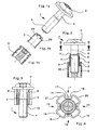
- FIGS. 1a, b and c the screw 1 with the screw head 2, a thread-free shaft 3 and the thread 4 is shown.
- This screw is used in a support sleeve, which consists of the two in the Figures 1b and 1c sleeve elements shown, namely the inner intermittently 29 provided sleeve member 5 and the outer sleeve member 6, can be joined together.
- the inner sleeve member 5 and the outer sleeve member 6 are collapsible and in FIG. 2 in an exploded position with covered by screw 1 shown.
- the inner sleeve member 5 with its inwardly projecting collar 7 on the screw head 2 facing threaded end 8.
- the inner sleeve member 5 is inserted into the outer sleeve member 6 so that at the position shown, the outer sleeve member 6 with inwardly projecting projections 9 at the outwardly projecting collar 10 hangs at the end of the inner sleeve member 5, so that the outer sleeve member 6 is captively connected to the inner sleeve member 5 axially displaceable.
- the two sleeve members 5 and 6 can be pushed together axially and moved against the head 2 of the screw 1, where they then occupy a position as shown in the FIG. 3 is shown.
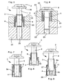
- FIG. 4 is the support sleeve according to the FIGS. 1 to 3 shown in section along the line IV-IV.
- the outer sleeve member 6 has a radial flexibility to give, this is based on the design of the support sleeve according to the above-mentioned EP 1 468 199 B1 provided with four indentations 11, 12, 13 and 14, which are each formed by the two walls 15 and 16 and the bottom 17. Between the indentations 11, 12, 13 and 14, these connecting beads 18, 19, 20 and 21 extend.
- This design of the outer sleeve member 6 allows it to compress radially due to the resilient resilience of the support sleeve material and thereby introduce into a breakthrough of a component, whose diameter is less than the diameter of the relaxed in FIG. 4 shown outer sleeve member 6. This operation is in the above-mentioned EP 1 468 199 B1 described in detail, to which reference is made in this context.
- FIGS. 5 and 6 Let the assembly of screw 1 with inner sleeve element 5 and outer sleeve element 6 with the carrier 22 and the component 23 to be fastened thereto be represented.
- the outer sleeve member 6 is inserted, which thereby resiliently against the wall of the opening 24 applies (see explanations to FIG. 4 ), which results in a guide for the protruding screw 1 with its thread 4, so that it finds in the nut thread 25 of the carrier 22 and can be screwed into this nut thread.
- FIGS. 7 and 8 variants of the design of the inner and outer sleeve member 5, 6 and the length of the thread 4 are shown.
- the outer sleeve member 6a has the same length as the length of the thread 4.
- the outer sleeve member 6c is unique from the embodiments discussed above.
- the outer sleeve element 6c At its end facing the screw head 2, the outer sleeve element 6c has an inwardly directed projection 9a, which is supported behind the outwardly projecting collar 10 of the inner sleeve element 5 and thus prevents the withdrawal of the outer sleeve element 6c from the inner sleeve element 5.
- the outer sleeve member 6c has a recess 27 at a short distance from the projection 9a, which prevents the outer sleeve member 6c from sliding over the inner sleeve member 5 without any inhibition.
Description
Die Erfindung bezieht sich auf eine in einen Durchbruch eines Bauteils einbringbare und in diesem durch Radialspannung gehaltene metallische Stützhülse, deren Loch von einer in einen Träger eindrehbaren Schraube mit Schraubenkopf zur Befestigung des Bauteils an dem Träger durchsetzt ist, die mit einem über eine Anfangslänge der Schraube sich erstreckenden Gewinde und danach mit einem bis zum Schraubenkopf reichenden gewindefreien Schaft versehen ist.The invention relates to an insertable in a breakthrough of a component and held in this by radial tension metallic support sleeve whose hole is penetrated by a screwed into a carrier screw with screw head for attachment of the component to the carrier, with a over an initial length of the screw extending thread and then provided with a reaching to the screw head unthreaded shaft.
Eine derartige Stützhülse ist in der
In der
Eine ähnliche Gestaltung ist in der
Erfindungsgemäß geschieht dies dadurch, dass die Stützhülse aus zwei ineinander teleskopartig einschiebbaren, metallischen Hülsenelementen besteht, deren inneres Hülsenelement an seinem dem Schraubenkopf zugewandten Ende mit einem nach innen ragenden Bund versehen ist, der hinter das Gewindeende der Schraube im Bereich von deren gewindefreien Schaft greift und mit seinem dem Schraubenkopf abgewandten Ende mit einem nach außen ragenden Bund hinter nach innen ragende Vorsprünge im Bereich von dem dem Schraubenkopf zugewandten Ende des äußeren Hülsenelementes greift, wobei der gewindefreie Schaft und das Gewinde zusammen eine solche Länge aufweisen, dass bei auseinander geschobener Stützhülse und hinter das Gewindeende greifendem Bund des inneren Hülsenelementes das Gewinde nicht aus dem äußeren Hülsenelement heraus ragt und bei zusammen geschobener Stützhülse und in den Träger eingedrehter Schraube das äußere Hülsenelement den Schraubenkopf gegen den Träger abstützt.According to the invention, this is done in that the support sleeve consists of two telescopically insertable, metallic sleeve elements, the inner sleeve member is provided at its end facing the screw head with an inwardly projecting collar which engages behind the threaded end of the screw in the range of their thread-free shaft and with its end facing away from the screw head engages with an outwardly projecting collar behind inwardly projecting projections in the region of the screw head facing the end of the outer sleeve member, the thread-free shaft and the thread together have such a length that when pushed apart support sleeve and behind the threaded end of the gripping collar of the inner sleeve member, the thread does not protrude from the outer sleeve member and when pushed together support sleeve and screwed into the carrier screw the outer sleeve member the screw head against the carrier abst TZT.
Eine teleskopartige Gestaltung von Stützhülsen ist an sich bekannt. So zeigt die
Die aus zwei ineinander teleskopartig einschiebbaren metallischen Hülsenelementen bestehende Stützhülse hält zunächst die Schraube im Bereich ihres gewindefreien Schaftes fest, womit ein unverlierbarer Verbund vorliegt. Dabei halten die auseinander geschobenen Hülsenelemente die Schraube zunächst in einer Lage, in der ihr dem Schraubenkopf abgewandtes Gewindeende nicht aus dem äußeren Hülsenelement herausragt, so dass in dieser Position eine lagerichtige Positionierung von Bauteil und Träger mit auseinandergezogener metallischer Stützhülse ohne störende Schraubenenden möglich ist. Auf diese Weise werden bei einer Schraubverbindung von Träger und Bauteil mittels einer größeren Zahl von Schrauben diese in die durchgehend richtige Position gebracht, woraufhin dann die Schrauben durch das innere Hülsenelement gedreht werden, um dabei in die betreffenden Schraubenlöcher des Trägers sich einzupassen, womit über eine größere Fläche bzw. Umfang eine sichere passende Zusammenfügung von Träger und Bauteil erzielt ist. Dabei schiebt sich jeweils das innere Hülsenelement in das äußere Hülsenelement, bis das äußere Hülsenelement die Stützfunktion der Stützhülse übernimmt, indem es einerseits Kontakt mit dem Schraubenkopf aufnimmt und andererseits gegen den Träger drückt, womit die notwendige und gewünschte Stützfunktion zwischen Schraube und Träger erzielt ist.The consisting of two telescopically insertable metallic sleeve elements support sleeve first holds the screw in the area of its thread-free shaft, which is a captive bond. The pushed apart sleeve elements hold the screw initially in a position in which her screw head remote from the threaded end does not protrude from the outer sleeve member, so that in this position, a correct position positioning of the component and support with exploded metallic support sleeve without disturbing screw ends is possible. In this way, in a screw connection of the carrier and component by means of a larger number of screws this brought into the correct correct position, whereupon then the screws are rotated by the inner sleeve member to thereby fit into the respective screw holes of the wearer, which over a larger surface or circumference a secure matching assembly of carrier and component is achieved. In each case, the inner sleeve member pushes into the outer sleeve member until the outer sleeve member takes over the support function of the support sleeve by one hand receives contact with the screw head and on the other hand presses against the carrier, whereby the necessary and desired support function between screw and carrier is achieved.
Die Stützhülse lässt sich folgendermaßen gestalten. Zunächst ist es vorteilhaft, dem äußeren Hülsenelement höchstens eine Länge zu geben, die gleich der Länge des Gewindes ist. Dabei ist es möglich, die Länge des äußeren Hülsenelementes kürzer als die Länge des Gewindes auszubilden.The support sleeve can be designed as follows. First, it is advantageous to give the outer sleeve member at most a length which is equal to the length of the thread. It is possible to make the length of the outer sleeve member shorter than the length of the thread.
Eine weitere zweckmäßige Anpassbarkeit von Gewinde und Stützhülse besteht darin, dass bei auseinander geschobener Stützhülse deren Länge höchstens gleich als die Länge des Gewindes ist, insbesondere größer sein kann.Another expedient adaptability of the thread and the support sleeve is that when the support sleeve is pushed apart, its length is at most equal to the length of the thread, in particular may be greater.
Der nach innen ragende Bund des inneren Hülsenelementes, mit dem dieser hinter das Gewinde der Schraube deren Schaft umgreift, kann als durchgehender Ringbund dem inneren Hülsenelement eingeprägt werden, es besteht aber auch die Möglichkeit, diesen Bund mit Unterbrechungen zu gestalten, so dass nur an einigen Stellen des inneren Hülsenelementes der Bund nach innen einzuprägen ist.The inwardly projecting collar of the inner sleeve member, with this behind the thread of the screw engages the shaft, can be stamped as a continuous collar the inner sleeve member, but it is also possible to make this covenant with interruptions, so that only some Make the inner sleeve member of the collar is to be embossed inside.
Um eine Verrasterung zwischen äußerem Hülsenelement und innerem Hülsenelement zu erzielen, kann man vorteilhaft am äußeren Hülsenelement nach innen ragende Einbuchtungen vorsehen, die den Vorsprüngen am äußeren Hülsenelement derart benachbart sind, dass der Bund am inneren Hülsenelement zwischen die Vorsprünge und die Einbuchtungen einrastbar ist. Diese Gestaltung hat den Vorteil, dass beim Zusammenfügen der beiden Hülsenelemente das innere Hülsenelement mit seinen nach außen ragenden Bund zwischen Vorsprünge und die nach innen ragenden Einbuchtungen am äußeren Hülsenelement einrastet, wobei diese Verrasterung aber keine Befestigung ist, sondern es nach wie vor erlaubt, dass das innere Hülsenelement beim Verschrauben aus dem Zwischenraum zwischen den nach innen ragenden Vorsprüngen und Einbuchtungen am äußeren Hülsenelement ausrasten, womit sich das innere Hülsenelement dann leicht gegenüber dem äußeren Hülsenelement verschieben lässt, bis beide Hülsenelemente praktisch nebeneinander liegen.In order to achieve a Verrasterung between outer sleeve member and inner sleeve member, one can advantageously provide on the outer sleeve member inwardly projecting indentations which are adjacent to the projections on the outer sleeve member such that the collar on the inner sleeve member between the projections and the recesses is latched. This design has the advantage that when assembling the two sleeve elements, the inner sleeve member engages with its outwardly projecting collar between projections and the inwardly projecting indentations on the outer sleeve member, said Verrasterung but no attachment, but it still allows that disengage the inner sleeve member when screwing out of the space between the inwardly projecting projections and indentations on the outer sleeve member, whereby the inner sleeve member can then easily move relative to the outer sleeve member until both sleeve elements are practically adjacent.
Um in der Stellung vor Einschrauben der Schraube diese mit ihrem Gewinde im inneren Hülsenelement zu halten, kann man das innere Hülsenelement so gestalten, dass es den Schaft der Schraube klemmend hält.In order to hold in the position before screwing the screw with its thread in the inner sleeve member, you can make the inner sleeve member so that it holds the shank of the screw by clamping.
Um die Abstützung des äußeren Hülsenelementes gegen den Träger zu stärken, kann man an dem äußeren Hülsenelement auf seiner dem Schraubenkopf abgewandten Seite einen Flansch zur Auflage an dem Träger anordnen.In order to strengthen the support of the outer sleeve member against the carrier, one can arrange on the outer sleeve member on its side facing away from the screw head a flange for support on the carrier.
In den Figuren sind Ausführungsbeispiele der Erfindung dargestellt. Es zeigen:
- Figuren 1a, b und c
- eine perspektivische Darstellung der auseinandergezogenen Teile der Stützhülse mit Schraube, und zwar jeweils allein die Schraube, das innere Hülsenelement und das äußere Hülsenelement;
Figur 2- die Stützhülse mit Schraube, wobei das innere und das äußere Hülsenelement im Schnitt gezeichnet sind;
Figur 3- die Schraube mit der aus
Figur 2 Figur 4- einen Schnitt längs der Linie IV-IV aus
Figur 2 Figur 5- Schraube und Stützhülse, wie dargestellt in
Figur 2 Figur 6- die in den Träger eingedrehte Schraube mit im Bereich des Durchbruchs zusammen geschobenen Hülsenelementen;
Figur 7- eine Anordnung
ähnlich Figur 2 , wobei das äußere Hülsenelement gleich der Länge des Gewindes ist; - Figur 8
- eine Anordnung
ähnlich Figur 7 , wobei die Länge des Gewindes gleich der Länge der auseinander geschobenen Stützhülse ist; Figur 9- eine Stützhülse mit äußerem Hülsenelement, in das das innere Hülsenelement eingerastet ist, wobei das äußere Hülsenelement einen Flansch besitzt.
- FIGS. 1a, b and c
- a perspective view of the exploded parts of the support sleeve with screw, in each case only the screw, the inner sleeve member and the outer sleeve member;
- FIG. 2
- the support sleeve with screw, wherein the inner and the outer sleeve member are drawn in section;
- FIG. 3
- the screw with the out
FIG. 2 apparent support sleeve, wherein the inner sleeve member is inserted into the outer sleeve member; - FIG. 4
- a section along the line IV-IV
FIG. 2 ; - FIG. 5
- Screw and support sleeve as shown in
FIG. 2 , used in the breakthrough of a component which rests on a support; - FIG. 6
- the screw screwed into the support with sleeve elements pushed together in the region of the opening;
- FIG. 7
- an arrangement similar
FIG. 2 wherein the outer sleeve member is equal to the length of the thread; - FIG. 8
- an arrangement similar
FIG. 7 wherein the length of the thread is equal to the length of the telescoped support sleeve; - FIG. 9
- a support sleeve having an outer sleeve member into which the inner sleeve member is latched, the outer sleeve member having a flange.
In den
Die beiden Hülsenelemente 5 und 6 können axial zusammengeschoben werden und gegen den Kopf 2 der Schraube 1 verschoben werden, wo sie dann eine Lage einnehmen, wie sie in der
In der
Anhand der
In eingeschraubter Lage ist die Schraube 1 in
In den
Gemäß
Bei der Ausführungsform gemäß
Bei der Ausführungsform gemäß
Claims (7)
- Into an opening (24) of a component (23) insertable and therein held by radial clamping metallic support sleeve (5, 6), the hole of which is passed by a screw (1) with a screw head (2) for attachment of the component (23) on the support (22) the screw adapted to be screwed into a carrier (22), which sleeve is provided with a thread (4) extending across an initial length of the screw and then with an unthreaded shank (3) reaching up to the screw head (2), characterized in that the support sleeve (5, 6) consists of two interlocking telescopically insertable, metallic sleeve members, the inner sleeve member (5) of which is provided at its end facing the screw head (2) with an inwardly projecting collar (7) which grips behind the threaded end (8) of the screw (1) in the area of the unthreaded shank (3) and which grips with its end facing away from the screw head (2) with an outwardly projecting collar (10) behind inwardly projecting projections (9) in the area of the end of the outer sleeve member (6) facing the screw head (2), wherein the unthreaded shank (3) and the thread (4) together have such a length, that with the support sleeve pushed apart and the threaded end (8) gripping behind the collar (7) of the inner sleeve member (5), the thread (4) does not project from the outer sleeve member (6); and with the telescoped support sleeve (5) pushed into the carrier (22) and the screw (1) screwed into the carrier (22), the outer sleeve member (6) supports the screw head (2 ) against the carrier (22).
- Supporting sleeve according to claim 1, characterized in that the length of the outer sleeve member (6) is at most equal to the length of the thread (4).
- Supporting sleeve according to claim 1 or 2, characterized in that, when pushed apart the length is of the supporting sleeve (5, 6) is at most equal to the length of the thread (4).
- Support sleeve according to one of claims 1 to 3, characterized in that the inwardly projecting collar (7) comprises interruptions (29).
- Support sleeve according to one of claims 1 to 4, characterized in that the inwardly projecting projections (9a) on the outer sleeve member (6c) are next to inwardly projecting indentations (27) such that the outwardly projecting collar (10) on the inner sleeve member (5) can be latched between the projections (9a) and the indentations (27).
- Support sleeve according to one of claims 1 to 5, characterized in that the shaft (3) is held clamped in the inner sleeve member (5).
- Support sleeve according to one of claims 1 to 6, characterized in that the outer sleeve member (6) carries a flange (28) on its side facing away from the screw head (2) for resting on the support (22).
Applications Claiming Priority (1)
| Application Number | Priority Date | Filing Date | Title |
|---|---|---|---|
| DE102007026568A DE102007026568A1 (en) | 2007-06-08 | 2007-06-08 | support sleeve |
Publications (3)
| Publication Number | Publication Date |
|---|---|
| EP2000681A2 EP2000681A2 (en) | 2008-12-10 |
| EP2000681A3 EP2000681A3 (en) | 2010-08-18 |
| EP2000681B1 true EP2000681B1 (en) | 2012-05-23 |
Family
ID=39667643
Family Applications (1)
| Application Number | Title | Priority Date | Filing Date |
|---|---|---|---|
| EP20080006071 Expired - Fee Related EP2000681B1 (en) | 2007-06-08 | 2008-03-28 | Support sleeve |
Country Status (2)
| Country | Link |
|---|---|
| EP (1) | EP2000681B1 (en) |
| DE (1) | DE102007026568A1 (en) |
Families Citing this family (8)
| Publication number | Priority date | Publication date | Assignee | Title |
|---|---|---|---|---|
| EP2169685B1 (en) * | 2008-09-26 | 2012-02-22 | Areva NP | Connecting device for connecting a guide tube to a lower end nozzle in a nuclear fuel assembly |
| DE102009023790A1 (en) * | 2009-06-03 | 2010-12-09 | Elringklinger Ag | Screw for securing a first component to a second component |
| DE202009012255U1 (en) | 2009-09-10 | 2009-12-03 | Acument Gmbh & Co. Ohg | Force-absorbing connecting element |
| DE202009012531U1 (en) * | 2009-09-17 | 2010-01-07 | Sma Solar Technology Ag | Device for determining the position of a screw in a screw bushing |
| GB2478308A (en) * | 2010-03-02 | 2011-09-07 | Psm Internat Ltd | Compression limiter assembly |
| DE102017122236A1 (en) * | 2017-09-26 | 2019-03-28 | Illinois Tool Works Inc. | Fixing system for fastening a component to a carrier component |
| US11473612B2 (en) | 2017-11-07 | 2022-10-18 | Arnold Umformtechnik Gmbh & Co. Kg | Securing means for screws, and mounting unit |
| DE102018102349A1 (en) * | 2018-02-02 | 2019-08-08 | Illinois Tool Works Inc. | fastening system |
Family Cites Families (6)
| Publication number | Priority date | Publication date | Assignee | Title |
|---|---|---|---|---|
| US4732519A (en) | 1986-12-24 | 1988-03-22 | Illinois Tool Works Inc. | Fastener assembly with axial play |
| US4975008A (en) | 1989-03-31 | 1990-12-04 | Illinois Tool Works, Inc. | Fastener assembly with sealing grommet |
| US5782595A (en) * | 1995-12-23 | 1998-07-21 | Richard Bergner Gmbh & Co. | Assembly unit comprised of an assembly element and a fastening element |
| DE29804041U1 (en) * | 1998-03-07 | 1999-07-08 | Itw Automotive Prod Gmbh & Co | Attachment of an assembly part to a support part |
| DE10254999B4 (en) * | 2001-11-24 | 2010-04-01 | Richard Bergner Verbindungstechnik Gmbh & Co. Kg | assembly unit |
| DE10202267A1 (en) | 2002-01-22 | 2003-07-31 | Ejot Gmbh & Co Kg | support sleeve |
-
2007
- 2007-06-08 DE DE102007026568A patent/DE102007026568A1/en not_active Withdrawn
-
2008
- 2008-03-28 EP EP20080006071 patent/EP2000681B1/en not_active Expired - Fee Related
Also Published As
| Publication number | Publication date |
|---|---|
| DE102007026568A1 (en) | 2008-12-11 |
| EP2000681A2 (en) | 2008-12-10 |
| EP2000681A3 (en) | 2010-08-18 |
Similar Documents
| Publication | Publication Date | Title |
|---|---|---|
| EP2000681B1 (en) | Support sleeve | |
| EP1958825B1 (en) | Attachment device | |
| DE3424675C2 (en) | Hose coupling | |
| DE19828059C2 (en) | Connection fitting with a fastening projection divided by slots in retaining tongues | |
| DE112014002282T5 (en) | Slide fastener | |
| DE102011054861A1 (en) | Fastening element with tolerance compensation function | |
| EP2218923A2 (en) | Fastening device for assembling a rod element to a fitting rail | |
| DE102015118314A1 (en) | Method for attaching a fastener to a mounting rail and fastener | |
| EP1447576B1 (en) | Plastic nut for a construction unit exhibiting a break-through | |
| DE102010051372A1 (en) | Connecting element with integrated snap connection | |
| WO2017109099A1 (en) | Adjustable spacer sleeve | |
| EP1703191A2 (en) | Conduit coupling | |
| EP2712413B1 (en) | Connecting device for connecting a fluid line | |
| EP3488133A1 (en) | Device for the sealed passing-through of an elongate part | |
| EP2240701B1 (en) | Engagement unit for attaching and for engaging a threaded bolt | |
| EP3122981B1 (en) | Sealing device and means for fixation | |
| DE202005010186U1 (en) | Bearing device for bearing element to put in C-shaped profile rail has fastening nut and bearing part with hole on its bearing flank holding neck part which has hole to take nut and spacer between neck part and flank | |
| EP3117046B1 (en) | Intermediate holder | |
| EP2980425B1 (en) | Fastening assembly for c-shaped attachment strips and kit | |
| DE3506127A1 (en) | Mounting device for at least two parts which are to be connected to one another, preferably on motor vehicles | |
| DE102013208494A1 (en) | Device for toolless connection of components i.e. furnitures, in furniture industry, has outer flange whose front end comprising recess for holding of other outer flange, and connection pin provided for introduction into hollow dowels | |
| DE102007042034A1 (en) | Fixing system for fastening components, in particular for motor vehicles | |
| DE102012022239A1 (en) | Component for attachment to a carrier component of an automobile | |
| DE202005004524U1 (en) | Plug-in connection for joining pipe to fitting, comprising clamping ring with additional projections on outer surface | |
| DE3732895C2 (en) |
Legal Events
| Date | Code | Title | Description |
|---|---|---|---|
| PUAI | Public reference made under article 153(3) epc to a published international application that has entered the european phase |
Free format text: ORIGINAL CODE: 0009012 |
|
| AK | Designated contracting states |
Kind code of ref document: A2 Designated state(s): AT BE BG CH CY CZ DE DK EE ES FI FR GB GR HR HU IE IS IT LI LT LU LV MC MT NL NO PL PT RO SE SI SK TR |
|
| AX | Request for extension of the european patent |
Extension state: AL BA MK RS |
|
| PUAL | Search report despatched |
Free format text: ORIGINAL CODE: 0009013 |
|
| AK | Designated contracting states |
Kind code of ref document: A3 Designated state(s): AT BE BG CH CY CZ DE DK EE ES FI FR GB GR HR HU IE IS IT LI LT LU LV MC MT NL NO PL PT RO SE SI SK TR |
|
| AX | Request for extension of the european patent |
Extension state: AL BA MK RS |
|
| 17P | Request for examination filed |
Effective date: 20110218 |
|
| AKX | Designation fees paid |
Designated state(s): DE FR IT |
|
| GRAP | Despatch of communication of intention to grant a patent |
Free format text: ORIGINAL CODE: EPIDOSNIGR1 |
|
| GRAS | Grant fee paid |
Free format text: ORIGINAL CODE: EPIDOSNIGR3 |
|
| GRAA | (expected) grant |
Free format text: ORIGINAL CODE: 0009210 |
|
| AK | Designated contracting states |
Kind code of ref document: B1 Designated state(s): DE FR IT |
|
| REG | Reference to a national code |
Ref country code: DE Ref legal event code: R096 Ref document number: 502008007240 Country of ref document: DE Effective date: 20120719 |
|
| PLBE | No opposition filed within time limit |
Free format text: ORIGINAL CODE: 0009261 |
|
| STAA | Information on the status of an ep patent application or granted ep patent |
Free format text: STATUS: NO OPPOSITION FILED WITHIN TIME LIMIT |
|
| 26N | No opposition filed |
Effective date: 20130226 |
|
| REG | Reference to a national code |
Ref country code: DE Ref legal event code: R097 Ref document number: 502008007240 Country of ref document: DE Effective date: 20130226 |
|
| REG | Reference to a national code |
Ref country code: FR Ref legal event code: ST Effective date: 20131129 |
|
| PG25 | Lapsed in a contracting state [announced via postgrant information from national office to epo] |
Ref country code: FR Free format text: LAPSE BECAUSE OF NON-PAYMENT OF DUE FEES Effective date: 20130402 |
|
| PG25 | Lapsed in a contracting state [announced via postgrant information from national office to epo] |
Ref country code: IT Free format text: LAPSE BECAUSE OF NON-PAYMENT OF DUE FEES Effective date: 20130328 |
|
| PGFP | Annual fee paid to national office [announced via postgrant information from national office to epo] |
Ref country code: DE Payment date: 20210323 Year of fee payment: 14 |
|
| REG | Reference to a national code |
Ref country code: DE Ref legal event code: R119 Ref document number: 502008007240 Country of ref document: DE |
|
| PG25 | Lapsed in a contracting state [announced via postgrant information from national office to epo] |
Ref country code: DE Free format text: LAPSE BECAUSE OF NON-PAYMENT OF DUE FEES Effective date: 20221001 |