EP3396216B1 - Dichtung - Google Patents
Dichtung Download PDFInfo
- Publication number
- EP3396216B1 EP3396216B1 EP18168381.4A EP18168381A EP3396216B1 EP 3396216 B1 EP3396216 B1 EP 3396216B1 EP 18168381 A EP18168381 A EP 18168381A EP 3396216 B1 EP3396216 B1 EP 3396216B1
- Authority
- EP
- European Patent Office
- Prior art keywords
- sealing lip
- sealing
- sealed
- ring
- seal
- Prior art date
- Legal status (The legal status is an assumption and is not a legal conclusion. Google has not performed a legal analysis and makes no representation as to the accuracy of the status listed.)
- Active
Links
Images



Classifications
-
- F—MECHANICAL ENGINEERING; LIGHTING; HEATING; WEAPONS; BLASTING
- F16—ENGINEERING ELEMENTS AND UNITS; GENERAL MEASURES FOR PRODUCING AND MAINTAINING EFFECTIVE FUNCTIONING OF MACHINES OR INSTALLATIONS; THERMAL INSULATION IN GENERAL
- F16J—PISTONS; CYLINDERS; SEALINGS
- F16J15/00—Sealings
- F16J15/16—Sealings between relatively-moving surfaces
- F16J15/32—Sealings between relatively-moving surfaces with elastic sealings, e.g. O-rings
- F16J15/3204—Sealings between relatively-moving surfaces with elastic sealings, e.g. O-rings with at least one lip
- F16J15/3228—Sealings between relatively-moving surfaces with elastic sealings, e.g. O-rings with at least one lip formed by deforming a flat ring
-
- F—MECHANICAL ENGINEERING; LIGHTING; HEATING; WEAPONS; BLASTING
- F16—ENGINEERING ELEMENTS AND UNITS; GENERAL MEASURES FOR PRODUCING AND MAINTAINING EFFECTIVE FUNCTIONING OF MACHINES OR INSTALLATIONS; THERMAL INSULATION IN GENERAL
- F16J—PISTONS; CYLINDERS; SEALINGS
- F16J15/00—Sealings
- F16J15/16—Sealings between relatively-moving surfaces
- F16J15/32—Sealings between relatively-moving surfaces with elastic sealings, e.g. O-rings
- F16J15/3204—Sealings between relatively-moving surfaces with elastic sealings, e.g. O-rings with at least one lip
-
- F—MECHANICAL ENGINEERING; LIGHTING; HEATING; WEAPONS; BLASTING
- F16—ENGINEERING ELEMENTS AND UNITS; GENERAL MEASURES FOR PRODUCING AND MAINTAINING EFFECTIVE FUNCTIONING OF MACHINES OR INSTALLATIONS; THERMAL INSULATION IN GENERAL
- F16J—PISTONS; CYLINDERS; SEALINGS
- F16J15/00—Sealings
- F16J15/16—Sealings between relatively-moving surfaces
- F16J15/32—Sealings between relatively-moving surfaces with elastic sealings, e.g. O-rings
- F16J15/3284—Sealings between relatively-moving surfaces with elastic sealings, e.g. O-rings characterised by their structure; Selection of materials
-
- F—MECHANICAL ENGINEERING; LIGHTING; HEATING; WEAPONS; BLASTING
- F16—ENGINEERING ELEMENTS AND UNITS; GENERAL MEASURES FOR PRODUCING AND MAINTAINING EFFECTIVE FUNCTIONING OF MACHINES OR INSTALLATIONS; THERMAL INSULATION IN GENERAL
- F16J—PISTONS; CYLINDERS; SEALINGS
- F16J15/00—Sealings
- F16J15/16—Sealings between relatively-moving surfaces
- F16J15/32—Sealings between relatively-moving surfaces with elastic sealings, e.g. O-rings
- F16J15/3204—Sealings between relatively-moving surfaces with elastic sealings, e.g. O-rings with at least one lip
- F16J15/322—Sealings between relatively-moving surfaces with elastic sealings, e.g. O-rings with at least one lip supported in a direction perpendicular to the surfaces
-
- F—MECHANICAL ENGINEERING; LIGHTING; HEATING; WEAPONS; BLASTING
- F16—ENGINEERING ELEMENTS AND UNITS; GENERAL MEASURES FOR PRODUCING AND MAINTAINING EFFECTIVE FUNCTIONING OF MACHINES OR INSTALLATIONS; THERMAL INSULATION IN GENERAL
- F16J—PISTONS; CYLINDERS; SEALINGS
- F16J15/00—Sealings
- F16J15/16—Sealings between relatively-moving surfaces
- F16J15/32—Sealings between relatively-moving surfaces with elastic sealings, e.g. O-rings
- F16J15/3204—Sealings between relatively-moving surfaces with elastic sealings, e.g. O-rings with at least one lip
- F16J15/3232—Sealings between relatively-moving surfaces with elastic sealings, e.g. O-rings with at least one lip having two or more lips
-
- F—MECHANICAL ENGINEERING; LIGHTING; HEATING; WEAPONS; BLASTING
- F16—ENGINEERING ELEMENTS AND UNITS; GENERAL MEASURES FOR PRODUCING AND MAINTAINING EFFECTIVE FUNCTIONING OF MACHINES OR INSTALLATIONS; THERMAL INSULATION IN GENERAL
- F16J—PISTONS; CYLINDERS; SEALINGS
- F16J15/00—Sealings
- F16J15/16—Sealings between relatively-moving surfaces
- F16J15/32—Sealings between relatively-moving surfaces with elastic sealings, e.g. O-rings
- F16J15/3248—Sealings between relatively-moving surfaces with elastic sealings, e.g. O-rings provided with casings or supports
-
- F—MECHANICAL ENGINEERING; LIGHTING; HEATING; WEAPONS; BLASTING
- F16—ENGINEERING ELEMENTS AND UNITS; GENERAL MEASURES FOR PRODUCING AND MAINTAINING EFFECTIVE FUNCTIONING OF MACHINES OR INSTALLATIONS; THERMAL INSULATION IN GENERAL
- F16J—PISTONS; CYLINDERS; SEALINGS
- F16J15/00—Sealings
- F16J15/16—Sealings between relatively-moving surfaces
- F16J15/32—Sealings between relatively-moving surfaces with elastic sealings, e.g. O-rings
- F16J15/3268—Mounting of sealing rings
-
- Y—GENERAL TAGGING OF NEW TECHNOLOGICAL DEVELOPMENTS; GENERAL TAGGING OF CROSS-SECTIONAL TECHNOLOGIES SPANNING OVER SEVERAL SECTIONS OF THE IPC; TECHNICAL SUBJECTS COVERED BY FORMER USPC CROSS-REFERENCE ART COLLECTIONS [XRACs] AND DIGESTS
- Y10—TECHNICAL SUBJECTS COVERED BY FORMER USPC
- Y10S—TECHNICAL SUBJECTS COVERED BY FORMER USPC CROSS-REFERENCE ART COLLECTIONS [XRACs] AND DIGESTS
- Y10S277/00—Seal for a joint or juncture
- Y10S277/935—Seal made of a particular material
- Y10S277/944—Elastomer or plastic
-
- Y—GENERAL TAGGING OF NEW TECHNOLOGICAL DEVELOPMENTS; GENERAL TAGGING OF CROSS-SECTIONAL TECHNOLOGIES SPANNING OVER SEVERAL SECTIONS OF THE IPC; TECHNICAL SUBJECTS COVERED BY FORMER USPC CROSS-REFERENCE ART COLLECTIONS [XRACs] AND DIGESTS
- Y10—TECHNICAL SUBJECTS COVERED BY FORMER USPC
- Y10S—TECHNICAL SUBJECTS COVERED BY FORMER USPC CROSS-REFERENCE ART COLLECTIONS [XRACs] AND DIGESTS
- Y10S277/00—Seal for a joint or juncture
- Y10S277/935—Seal made of a particular material
- Y10S277/944—Elastomer or plastic
- Y10S277/945—Containing fluorine
- Y10S277/946—PTFE
Definitions
- the invention relates to a seal comprising a support ring and at least one sealing ring, the sealing ring and the support ring being connected to one another, the support ring having an outer circumference and being at least partially enclosed on the outer circumference in the radial direction by a casing of the sealing ring, the sealing ring at least one has dynamically stressed sealing lip, which is arranged on the side of the sealing ring radially facing away from the casing, the sealing ring being made of an electrically conductive and polymeric material and the casing and the sealing lip being formed integrally into one another, the dynamically stressed sealing lip as an upstream sealing lip is formed and wherein the dynamically stressed sealing lip has a dynamically stressed further sealing lip as the main sealing lip for sealing a medium to be sealed in a space to be sealed in a functional series connection in axial direction caution is upstream.
- PTFE polymer material for the sealing ring
- PTFE polymer material for the sealing ring
- PTFE polymer material for the sealing ring
- PTFE polymer material for the sealing ring
- the seal comprises a carrier part made of a metallic material which is enclosed by a coating made of an elastomer.
- the seal is produced in that the carrier part is first produced separately and coated with a complete coating.
- the sealing element is also produced separately.
- the carrier part and the sealing element are then connected to form a structural unit by means of an adhesive connection.
- the support ring consists of a tough, hard material, for example a metallic or a polymer material.
- the sealing ring is connected directly or indirectly to the support ring, the sealing ring being made of an elastomeric material.
- the known seal comprises a substantially circular ring-shaped disk made of an electrically conductive and air-permeable material, the disk - based on the support ring - is designed as a separately produced item and connected to the support ring.
- the disc consists of an electrically conductive nonwoven and is designed as an upstream seal. The upstream seal is assigned to the sealing lip of the sealing ring adjacent to it at an axial distance.
- the upstream seal is arranged on the side of the sealing lip facing the environment.
- the upstream seal has the task of preventing impurities from the environment from penetrating the sealing lip. As a result, consistently good performance properties of the seal are achieved over a long period of use.
- the sealing ring of this seal consists of an elastomeric material that is electrically conductive.
- the seal is used to seal components that include toothed parts, with charge separations taking place when these toothed parts move.
- the resulting currents are partly diverted by the medium to be sealed, that is, the lubricant used, and partly currents are passed on to the components to be sealed against one another.
- the electrically conductive and elastomeric material has the advantage that currents can easily be diverted through the sealing ring.
- the dynamically stressed sealing lip is assigned a dust lip on the side facing away from the space to be sealed, which is formed in one piece and made of the same material with the sealing lip and consequently also consists of an electrically conductive and elastomeric material.
- elastomeric materials must always be sufficiently lubricated during their intended use in order to achieve a satisfactory service life Lubrication normally takes place through the medium to be sealed. If the lubrication is inadequate during the intended use of the seal, the elastomeric material of the sealing ring wears out quickly and the seal has deteriorated performance properties after a short period of use.
- the invention is based on the object of further developing a seal of the type mentioned in such a way that it has consistently good performance properties over a long period of use, even if it is only poorly or not at all lubricated by the medium to be sealed from the space to be sealed.
- the seal should also reliably prevent electrostatic charging and the resulting damage to the machine elements to be sealed against one another, and the support ring should be well protected from external influences.
- the sealing ring indirectly contacts the support ring by means of an elastomer track
- the support ring (1) is essentially L-shaped, with one radial leg (7) and one on the outside in the radial direction (4) the radial leg (7) adjoining axial leg (8) that the elastomer track completely encloses the axial leg and the radial leg, that radially inner circumference on a radial leg of the support ring, in the axial direction between the dynamically loaded sealing lip and the dynamically loaded further sealing lip, one with the material the elastomer track uniformly formed elastomer sealing lip is arranged, which - in the installed state of the seal - sealingly encloses a surface to be sealed of a shaft to be sealed under radial prestress.
- the sealing ring touches the support ring indirectly by means of an elastomer track.
- the elastomer track completely encloses the axial leg and the radial leg.
- the advantage here is that the support ring is thereby particularly well protected against external influences, for example against exposure to moisture.
- the elastomer sealing lip can be designed as an upstream sealing lip for the further sealing lip and this can be connected axially upstream in the direction of the surroundings.
- the seal has the advantage that polymeric materials - in contrast to elastomeric materials - have largely consistently good performance properties over a long period of use even if they are only poorly lubricated. For this reason, the dynamically stressed sealing lip can easily be considered practically non-lubricated Upstream seal can be arranged on the side of a main sealing lip facing the environment.
- an electrically conductive polymer material has the advantage that the pressure of the sealing lip against a surface to be sealed of a machine element to be sealed is practically constant over the entire service life.
- a sealing lip which consists of an electrically conductive non-woven material
- a sealing lip made of a polymer material can withstand dry running comparatively well, a polymer material does not absorb moisture and can also reliably seal machine elements to be sealed over a long period of use, those at high speeds , for example, be 20,000 min -1, operated as.
- sealing rings made of a polymer material have the advantage over sealing rings made of a nonwoven that they can better compensate for any possible shaft misalignment of a shaft to be sealed.
- the electrically conductive and polymeric material of the sealing ring creates a decoupled electrical bridge between the machine elements to be sealed against each other.
- These machine elements to be sealed against each other can be formed, for example, by a shaft to be sealed with a surface to be sealed and a housing that surrounds the shaft to be sealed at a radial distance on the outer circumference, the seal being arranged in the gap formed by the distance.
- the dynamically stressed sealing lip is designed as an upstream sealing lip.
- An upstream sealing lip is a decoupled electrical bridge.
- “decoupled” is understood to mean that the sealing function of a main sealing lip that is used is decoupled from the function of an electrical bridge that is formed by the upstream sealing lip.
- the upstream sealing lip is not in direct contact with the medium to be sealed.
- the advantage here is that the electrical resistance of the front sealing lip is essentially constant during the entire service life. If the upstream sealing lip were to come into contact with the medium to be sealed, the resistance would change continuously and in an uncontrolled manner during the intended use of the seal.
- the dynamically stressed sealing lip is preceded by a dynamically stressed further sealing lip as the main sealing lip for sealing a medium to be sealed in a space to be sealed in a functional series connection in the axial direction.
- the material from which such a further sealing lip is made can be adapted to the particular circumstances of the application. It is not necessary that the further sealing lip is also designed to be electrically conductive.
- the electrically conductive and polymeric material is a PTFE material.
- a PTFE material has the advantages described above in particular because sealing lips made from this material have practically self-lubricating properties. A sealing lip made of such a material has therefore, even after a long period of use, there is almost no wear and tear and therefore always largely the same properties.
- the casing and the sealing lip are preferably made of the same material.
- the advantage here is that such a seal can be produced simply and inexpensively in terms of production technology. Should the particular circumstances of the application make it advantageous to manufacture the casing and the sealing lip from materials that differ from one another, these two polymer materials that differ from one another are each electrically conductive in order to be able to dissipate electrostatic charges from the sealing arrangement that comprises the seal.
- the support ring is essentially L-shaped, with a radial leg and an axial leg adjoining the radial leg on the outside in the radial direction.
- the support ring can consist of a metallic or a polymer material.
- An electrical conductivity of the support ring is not necessary for the advantageous properties of use of the seal, because an electrical voltage breakdown is avoided by the fact that the sealing ring consists of an electrically conductive polymer from the sealing lip to the casing.
- the dynamically stressed sealing lip is usually articulated radially on the inside of the radial leg.
- the casing is supported radially on the outside by the axial leg.
- the axial leg can be completely enclosed on the outer circumference by the casing.
- the advantage here is that the electrical conductivity of the The seal is particularly reliable due to the good support of the casing by the axial leg.
- the casing extends, in the radial direction along the radial leg, integrally merging into one another up to the dynamically stressed sealing lip. This results in a simple electrically conductive connection between the machine elements to be sealed against one another, for example between a shaft to be sealed and a housing which surrounds the shaft to be sealed on the circumferential side.
- the electrically conductive sealing ring effects a controlled electrical equipotential bonding between the machine elements to be sealed against each other. Mechanical damage to the machine elements through electrostatic charging of one of the machine elements and a subsequent voltage breakdown to the other machine element with a different electrical potential are consequently excluded.
- one of the machine elements to be sealed against each other is grounded to a defined ground potential (for example the body of a motor vehicle as electrical ground potential), so that the electrically conductive sealing ring achieves potential equalization with the other machine element .
- a defined ground potential for example the body of a motor vehicle as electrical ground potential
- the dynamically stressed sealing lip is designed as a main sealing lip for sealing a medium to be sealed in a space to be sealed.
- the dynamically stressed sealing lip is during the Intended use of the seal mostly bulged axially in the direction of the space to be sealed.
- the sealing lip radially facing the machine element to be sealed it can have a surface profile, for example, wherein the surface profile can have, for example, lubricant pockets and / or a return spiral.
- the dynamically stressed further sealing lip can consist of a polymer or an elastomer material. If a polymer material is used, for example a PTFE material, separately produced spring elements, such as helical coil springs for example, are unnecessary, which press the further sealing lip against the machine element to be sealed under elastic radial prestress.
- a spring element for example an annular helical spring.
- the spring element ensures good sealing by the additional sealing lip on the surface of the machine element to be sealed to be sealed.
- the support ring can consist of a metallic material. Such support rings can be produced easily and inexpensively in many dimensions.
- the first machine element can be formed by a drive shaft of an electric motor, the second machine element by a housing of a gear connected to the electric motor and enclosing the drive shaft.
- FIGS Figures 1 to 4 Two examples not according to the invention and two exemplary embodiments of the claimed seal are shown in FIGS Figures 1 to 4 shown schematically and are described in more detail below.
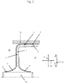
- FIG. 1 to 4 an exemplary embodiment of a seal is shown in each case, the exemplary embodiments according to FIG Figures 1 and 2 are not according to the invention.
- the seal comprises a support ring 1 and a sealing ring 2, the sealing ring 2 being fixed on the support ring 1.
- the support ring 1 is L-shaped and comprises a radial leg 7 and an axial leg 8, which is completely enclosed in the circumferential direction 12 by the casing 5.
- the sealing ring 2 comprises a dynamically stressed sealing lip 6, which is arranged on the side of the sealing ring 2 radially facing away from the casing 5.
- the sealing ring 2 consists of an electrically conductive and polymeric material, in the exemplary embodiments shown, of a PTFE material, the casing 5 and the sealing lip 6 being formed integrally and merging into one another.
- the sealing ring 2 is electrically conductive from the sealing lip 6 to the casing 5 in order to ensure electrical equipotential bonding between a shaft 13 to be sealed and a housing 14 which surrounds the shaft 13 to be sealed at a radial distance on the outer circumference. This prevents electrostatic charging between the shaft 13 to be sealed and the housing 14, as well as a voltage breakdown which could damage the machine elements 13, 14 to be sealed against one another.
- the casing 5 of the sealing ring not only ensures the potential equalization described above, but is also designed to be statically sealing.
- a static seal to be produced separately for sealing against the housing 14 is therefore not required.
- FIG. 1 a first embodiment is shown, which is particularly simple and inexpensive to manufacture.
- the seal consists of only two parts, namely the support ring 1 and the sealing ring 2, the sealing ring 2 comprising the casing 5 and the sealing lip 6, which merge in one piece and are made of the same material.
- the sealing lip 6 is arched axially in the direction of a space 15 of the sealing arrangement to be sealed.
- the dynamically stressed sealing lip 6 is designed as an upstream sealing lip and bulges axially in the direction of the surroundings 16 of the sealing arrangement.
- the further sealing lip 9 is provided in this exemplary embodiment, which is provided as the main sealing lip for sealing the medium to be sealed in the space 15 to be sealed.
- the further sealing lip 9 is connected upstream of the dynamically stressed sealing lip 6 in a functional series connection, viewed from the space 15 to be sealed, in the axial direction 10.
- FIG. 3 a first embodiment according to the invention is shown, similar to the embodiment from FIG Figure 2 , the support ring 1 being completely enclosed by the elastomer track 11.
- the dynamically stressed sealing lip 6 and the dynamically stressed further sealing lip 9 are connected to the elastomer track 11, so that the sealing ring 2 indirectly contacts the support ring 1 by means of the elastomer track 11.
- an elastomer sealing lip 17 is arranged, which in the axial direction 10 between the dynamically stressed sealing lip 6 and the dynamically stressed further sealing lip 9 sealingly encloses the surface to be sealed of the shaft 13 to be sealed under radial prestress.
- FIG. 4 a second embodiment according to the invention is shown, similar to the embodiment from FIG Figure 3 , wherein instead of the dynamically stressed further sealing lip 9 consisting of a polymer material, a dynamically stressed further sealing lip 9 is used, which consists of an elastomeric material.
- This further sealing lip 9 is designed in the form of a conventional radial shaft sealing ring, it being pressed sealingly against the outer circumference of the shaft 13 to be sealed by an annular helical spring 18.
- an elastomer sealing lip 17 is arranged in the axial direction 10 between the dynamically stressed sealing lip 6 and the dynamically stressed further sealing lip 9, which forms an upstream seal for the further sealing lip 9 and which is upstream axially in the direction of the surroundings 16.
- the dynamically stressed sealing lip 6, which effects the electrical equipotential bonding consists of a wear-resistant polymer material, so that this sealing lip not only, as in FIG Figure 1 shown, can be arranged in the space to be sealed 15 with the medium to be sealed and thereby of medium to be sealed is lubricated. It can also, as in the Figures 2 to 4 shown, be arranged in the environment 16 and therefore not come into contact with the medium to be sealed in the space 15 to be sealed. Because of the advantageous polymeric material that is used, lubrication by the medium to be sealed is not necessary.
Landscapes
- Engineering & Computer Science (AREA)
- General Engineering & Computer Science (AREA)
- Mechanical Engineering (AREA)
- Sealing With Elastic Sealing Lips (AREA)
- Sealing Devices (AREA)
- Sealing Of Bearings (AREA)
Description
- Die Erfindung betrifft eine Dichtung, umfassend einen Tragring und zumindest einen Dichtring, wobei der Dichtring und der Tragring miteinander verbunden sind, wobei der Tragring einen Außenumfang aufweist und in radialer Richtung außenumfangsseitig von einer Ummantelung des Dichtrings zumindest teilweise umschlossen ist, wobei der Dichtring zumindest eine dynamisch beanspruchte Dichtlippe aufweist, die auf der der Ummantelung radial abgewandten Seite des Dichtrings angeordnet ist, wobei der Dichtring aus einem elektrisch leitfähigen und polymeren Werkstoff besteht und wobei die Ummantelung und die Dichtlippe einstückig in einander übergehend ausgebildet sind, wobei die dynamisch beanspruchte Dichtlippe als Vorschaltdichtlippe ausgebildet ist und wobei der dynamisch beanspruchten Dichtlippe eine dynamisch beanspruchte weitere Dichtlippe als Hauptdichtlippe zur Abdichtung eines abzudichtenden Mediums in einem abzudichtenden Raum in einer funktionstechnischen Reihenschaltung in axialer Richtung vorgeschaltet ist.
- Eine solche Dichtung ist aus der
US 2003/031828 A1 bekannt. Als polymerer Werkstoff für den Dichtring ist zum Beispiel PTFE genannt, das durch zumindest einen Füllstoff modifiziert sein kann, um bestimmte, gewünschte Dichtungseigenschaften, wie beispielsweise mechanische Festigkeit, Schmierfähigkeit, Wärmeleitfähigkeit und/oder elektrische Leitfähigkeit, Verschleißbeständigkeit oder Erscheinung, das heißt Farbe, bereitzustellen. - Aus der
EP 2 397 726 A1 ist eine weitere Dichtung bekannt sowie ein Verfahren zu deren Herstellung. Die Dichtung umfasst ein Trägerteil aus einem metallischen Werkstoff, das von einer Beschichtung aus einem Elastomer umschlossen ist. Die Dichtung wird dadurch hergestellt, dass zunächst das Trägerteil gesondert erzeugt und mit einer vollständigen Beschichtung beschichtet wird. Auch das Dichtelement wird gesondert erzeugt. Das Trägerteil und das Dichtelement werden dann durch eine Klebeverbindung zu einer Baueinheit verbunden. - Eine weitere Dichtung ist aus der
DE 10 2014 010 269 A1 bekannt. Der Tragring besteht aus einem zähharten Werkstoff, zum Beispiel einem metallischen oder einem polymeren Werkstoff. Der Dichtring ist mittelbar oder unmittelbar mit dem Tragring verbunden, wobei der Dichtring aus einem elastomeren Werkstoff besteht.
Außerdem umfasst die vorbekannte Dichtung eine im Wesentlichen kreisringförmig ausgebildete Scheibe aus einem elektrisch leitfähigen und luftdurchlässigen Werkstoff, wobei die Scheibe - bezogen auf den Tragring - als separat erzeugtes Einzelteil ausgebildet und mit dem Tragring verbunden ist. Die Scheibe besteht aus einem elektrisch leitfähigen Vliesstoff und ist als Vorschaltdichtung ausgebildet.
Die Vorschaltdichtung ist der Dichtlippe des Dichtrings mit axialem Abstand benachbart zugeordnet. Während der bestimmungsgemäßen Verwendung ist die Vorschaltdichtung auf der der Umgebung zugewandten Seite der Dichtlippe angeordnet.
Die Vorschaltdichtung hat die Aufgabe, Verunreinigungen aus der Umgebung an einem Vordringen zur Dichtlippe zu hindern. Dadurch werden gleichbleibend gute Gebrauchseigenschaften der Dichtung während einer langen Gebrauchsdauer erreicht. - Eine weitere Dichtung ist aus der
DE 103 40 802 A1 bekannt. Der Dichtring dieser Dichtung besteht aus einem elastomeren Werkstoff, der elektrisch leitfähig ist. Die Dichtung gelangt zur Abdichtung von Bauteilen zur Anwendung, die Verzahnungsteile umfassen, wobei bei Bewegung dieser Verzahnungsteile Ladungstrennungen stattfinden. Die dadurch entstehenden Ströme werden teilweise durch das abzudichtende Medium, also das verwendete Schmiermittel, abgeleitet, und teilweise werden Ströme an die gegeneinander abzudichtenden Bauteile weitergeleitet. Durch den elektrisch leitfähigen und elastomeren Werkstoff ist von Vorteil, dass Ströme einfach durch den Dichtring hindurch ableitbar sind.
In einem der vorbekannten Ausführungsbeispiele ist der dynamisch beanspruchten Dichtlippe auf der dem abzudichtenden Raum axial abgewandten Seite eine Staublippe zugeordnet, die einstückig und materialeinheitlich mit der Dichtlippe ausgebildet ist und folglich ebenfalls aus einem elektrisch leitfähigen und elastomeren Werkstoff besteht.
Dabei ist allerdings zu beachten, dass elastomere Werkstoffe während ihrer bestimmungsgemäßen Verwendung stets ausreichen geschmiert werden müssen, um eine zufriedenstellende Gebrauchsdauer zu erreichen, wobei die Schmierung normalerweise durch das abzudichtende Medium erfolgt. Ist die Schmierung während der bestimmungsgemäßen Verwendung der Dichtung mangelhaft, verschleißt der elastomere Werkstoff des Dichtrings rasch und die Dichtung weist bereits nach einer kurzen Gebrauchsdauer verschlechterte Gebrauchseigenschaften auf. - Der Erfindung liegt die Aufgabe zu Grunde, eine Dichtung der eingangs genannten Art derart weiterzuentwickeln, dass diese gleichbleibend gute Gebrauchseigenschaften während einer langen Gebrauchsdauer aufweist, auch dann, wenn sie nur mangelhaft oder gar nicht vom abzudichtenden Medium aus dem abzudichtenden Raum geschmiert wird. Die Dichtung soll außerdem eine elektrostatische Aufladung und eine daraus resultierende Beschädigung der gegeneinander abzudichtenden Maschinenelemente sicher verhindern, und der Tragring soll vor äußeren Einflüssen gut geschützt sein.
- Gelöst wird diese Aufgabe durch die Merkmale von Anspruch 1. Auf vorteilhafte Ausgestaltungen nehmen die Unteransprüche Bezug.
- Zur Lösung der Aufgabe ist es vorgesehen, dass der Dichtring den Tragring mittels einer Elastomerspur mittelbar anliegend berührt, dass der Tragring (1) im Wesentlichen L-förmig ausgebildet ist, mit einem Radialschenkel (7) und einem in radialer Richtung (4) außen an den Radialschenkel (7) anschließenden Axialschenkel (8), dass die Elastomerspur den Axialschenkel und den Radialschenkel vollständig umschließt, dass radial innenumfangsseitig an einem Radialschenkel des Tragrings, in axialer Richtung zwischen der dynamisch beanspruchten Dichtlippe und der dynamisch beanspruchten weiteren Dichtlippe, eine mit dem Material der Elastomerspur einheitlich ausgebildete Elastomerdichtlippe angeordnet ist, die - im eingebauten Zustand der Dichtung - eine abzudichtende Oberfläche einer abzudichtenden Welle unter radialer Vorspannung dichtend umschließt.
- Der Dichtring berührt den Tragring mittels einer Elastomerspur mittelbar anliegend.
- Die Elastomerspur umschließt den Axialschenkel und den Radialschenkel vollständig. Hierbei ist von Vorteil, dass der Tragring dadurch besonders gut vor äußeren Einflüssen, zum Beispiel vor einer Beaufschlagung mit Feuchtigkeit, geschützt ist.
- Die Elastomerdichtlippe kann als Vorschaltdichtlippe für die weitere Dichtlippe ausgebildet und dieser axial in Richtung der Umgebung vorgeschaltet sein.
- Die Dichtung hat den Vorteil, dass polymere Werkstoffe - im Gegensatz zu elastomeren Werkstoffen - auch dann weitgehend gleichbleibend gute Gebrauchseigenschaften während einer langen Gebrauchsdauer aufweisen, wenn sie nur mangelhaft geschmiert sind. Aus diesem Grund kann die dynamisch beanspruchte Dichtlippe problemlos als praktisch nicht-geschmierte Vorschaltdichtung auf der der Umgebung zugewandten Seite einer Hauptdichtlippe angeordnet sein.
Gegenüber einem elektrisch leitfähigen Vliesstoff hat ein elektrisch leitfähiger polymerer Werkstoff den Vorteil, dass die Anpressung der Dichtlippe an eine abzudichtende Oberfläche eines abzudichtenden Maschinenelements während der gesamten Gebrauchsdauer praktisch konstant ist.
Ebenfalls im Gegensatz zu einer Dichtlippe, die aus einem elektrisch leitfähigen Vliesstoff besteht, hält eine Dichtlippe aus einem polymeren Werkstoff Trockenlauf vergleichsweise gut aus, ein polymerer Werkstoff nimmt keine Feuchtigkeit auf und kann außerdem abzudichtende Maschinenelemente während einer langen Gebrauchsdauer sicher abdichten, die mit hohen Drehzahlen, zum Beispiel mit mehr als 20.000 min-1, betrieben werden. Außerdem haben Dichtringe aus einem polymeren Werkstoff im Vergleich zu Dichtringen aus einem Vliesstoff den Vorteil, dass sie einen möglichen Wellenversatz einer abzudichtenden Welle besser ausgleichen können. - Durch den elektrisch leitfähigen und polymeren Werkstoff des Dichtrings entsteht eine entkoppelte elektrische Brücke zwischen den gegeneinander abzudichtenden Maschinenelementen. Diese gegeneinander abzudichtenden Maschinenelemente können beispielsweise durch eine abzudichtende Welle mit einer abzudichtenden Oberfläche und einem Gehäuse gebildet sein, das die abzudichtende Welle mit radialem Abstand außenumfangsseitig umschließt, wobei in dem durch den Abstand gebildeten Spalt die Dichtung angeordnet ist.
- Die dynamisch beanspruchte Dichtlippe ist als Vorschaltdichtlippe ausgebildet. Bei einer Vorschaltdichtlippe handelt es sich um eine entkoppelte elektrische Brücke. Unter "entkoppelt" wird in diesem Zusammenhang verstanden, dass die Dichtfunktion einer zur Anwendung gelangenden Hauptdichtlippe von der Funktion einer elektrischen Brücke, die durch die Vorschaltdichtlippe gebildet ist, entkoppelt ist. Die Vorschaltdichtlippe steht dabei nicht in direktem Kontakt mit dem abzudichtenden Medium. Dabei ist von Vorteil, dass der elektrische Widerstand der Vorschaltdichtlippe während der gesamten Gebrauchsdauer im Wesentlichen konstant ist. Würde die Vorschaltdichtlippe mit dem abzudichtenden Medium in Kontakt gelangen, würde sich der Widerstand während der bestimmungsgemäßen Verwendung der Dichtung stets und unkontrolliert verändern.
- Der dynamisch beanspruchten Dichtlippe ist eine dynamisch beanspruchte weitere Dichtlippe als Hauptdichtlippe zur Abdichtung eines abzudichtenden Mediums in einem abzudichtenden Raum in einer funktionstechnischen Reihenschaltung in axialer Richtung vorgeschaltet. Der Werkstoff, aus dem eine derartige weitere Dichtlippe besteht, kann an die jeweiligen Gegebenheiten des Anwendungsfalles angepasst sein. Es ist nicht erforderlich, dass die weitere Dichtlippe ebenfalls elektrisch leitfähig ausgebildet ist.
- Gemäß einer vorteilhaften Ausgestaltung kann es vorgesehen sein, dass der elektrisch leitfähige und polymere Werkstoff ein PTFE-Werkstoff ist. Ein solcher Werkstoff weist die zuvor beschriebenen Vorteile in besonderem Maße auf, weil aus diesem Werkstoff bestehende Dichtlippen praktisch selbstschmierende Eigenschaften haben. Eine Dichtlippe aus einem solchen Werkstoff weist deshalb auch nach einer langen Gebrauchsdauer nahezu keinen Verschleiß und deshalb immer weitgehend dieselben Gebrauchseigenschaften auf.
- Die Ummantelung und die Dichtlippe sind bevorzugt materialeinheitlich ausgebildet. Hierbei ist von Vorteil, dass eine solche Dichtung fertigungstechnisch einfach und kostengünstig herstellbar ist.
Sollte es durch die jeweiligen Gegebenheiten des Anwendungsfalles vorteilhaft sein, die Ummantelung und die Dichtlippe aus voneinander abweichenden Werkstoffen herzustellen, sind diese beiden voneinander abweichenden polymeren Werkstoffe jeweils elektrisch leitfähig, um elektrostatische Aufladungen aus der Dichtungsanordnung, die die Dichtung umfasst, ableiten zu können. - Erfindungsgemäß ist es vorgesehen, dass der Tragring im Wesentlichen L-förmig ausgebildet ist, mit einem Radialschenkel und einem in radialer Richtung außen an den Radialschenkel anschließenden Axialschenkel.
- Generell kann der Tragring aus einem metallischen oder einem polymeren Werkstoff bestehen.
- Eine elektrische Leitfähigkeit des Tragrings ist für die vorteilhaften Gebrauchseigenschaften der Dichtung nicht erforderlich, weil ein elektrischer Spannungsdurchschlag dadurch vermieden wird, dass der Dichtring von der Dichtlippe bis zur Ummantelung aus einem elektrisch leitfähigen Polymer besteht.
- Radial innenseitig des Radialschenkels ist üblicherweise die dynamisch beanspruchte Dichtlippe angelenkt. Die Ummantelung ist demgegenüber durch den Axialschenkel radial außenseitig abgestützt.
- Der Axialschenkel kann von der Ummantelung außenumfangsseitig vollständig umschlossen sein. Hierbei ist von Vorteil, dass die elektrische Leitfähigkeit der Dichtung durch die gute Abstützung der Ummantelung durch den Axialschenkel besonders zuverlässig funktioniert.
- Die Ummantelung erstreckt sich, in radialer Richtung am Radialschenkel entlang, einstückig ineinander übergehend bis in die dynamisch beanspruchte Dichtlippe. Dadurch ergibt sich eine einfache elektrisch leitende Verbindung zwischen den gegeneinander abzudichtenden Maschinenelementen, zum Beispiel zwischen einer abzudichtenden Welle und einem Gehäuse, das die abzudichtende Welle umfangsseitig umschließt.
- Der elektrisch leitfähige Dichtring bewirkt einen kontrollierten elektrischen Potentialausgleich zwischen den gegeneinander abzudichtenden Maschinenelementen.
Eine mechanische Beschädigung der Maschinenelemente durch eine elektrostatische Aufladung eines der Maschinenelemente und ein anschließender Spannungsdurchschlag zum anderen Maschinenelement mit einem anderen elektrischen Potential sind folglich ausgeschlossen. - In der Dichtungsanordnung, in der der zuvor beschriebene Dichtring zur Anwendung gelangt, ist eines der gegeneinander abzudichtenden Maschinenelemente auf ein definiertes Massepotential (beispielsweise die Karosserie eines Kraftfahrzeugs als elektrisches Massepotential) geerdet, so dass durch den elektrisch leitfähigen Dichtring ein Potentialausgleich zum anderen Maschinenelement erreicht wird.
- Nach einer ersten Ausgestaltung kann es vorgesehen sein, dass die dynamisch beanspruchte Dichtlippe als Hauptdichtlippe zur Abdichtung eines abzudichtenden Mediums in einem abzudichtenden Raum ausgebildet ist. Hierzu ist die dynamisch beanspruchte Dichtlippe während der bestimmungsgemäßen Verwendung der Dichtung zumeist axial in Richtung des abzudichtenden Raums vorgewölbt.
Auf der dem abzudichtenden Maschinenelement radial zugewandten Seite der Dichtlippe kann diese zum Beispiel eine Oberflächenprofilierung aufweisen, wobei die Oberflächenprofilierung zum Beispiel Schmiermitteltaschen und/oder einen Rückförderdrall aufweisen kann. - Die dynamisch beanspruchte weitere Dichtlippe kann aus einem polymeren oder eleastomeren Werkstoff bestehen. Gelangt ein polymerer Werkstoff zur Anwendung, beispielsweise ein PTFE-Werkstoff, sind separat hergestellte Federelemente, wie beispielsweise Ringwendelfedern entbehrlich, die die weitere Dichtlippe unter elastischer radialer Vorspannung an das abzudichtende Maschinenelement andrücken.
- Gelangt demgegenüber ein elastomerer Werkstoff zur Anwendung, kann dessen Dichtlippe radial außenumfangsseitig von einem Federelement, beispielsweise einer Ringwendelfeder, umschlossen sein. Insbesondere bei stillstehender abzudichtender Welle und/oder bei einem nur geringen relativen Überdruck im abzudichtenden Raum sorgt das Federelement für eine gute Abdichtung durch die weitere Dichtlippe auf der abzudichtenden Oberfläche des abzudichtenden Maschinenelements.
- Der Tragring kann aus einem metallischen Werkstoff bestehen. Solche Tragringe sind in vielen Abmessungen einfach und kostengünstig herstellbar.
- Ohne einen elektrischen Potentialausgleich, wie er durch die zuvor beschriebene Dichtung bewirkt wird, könnten durch Spannungsdurchschläge mechanische Beschädigungen der gegeneinander abzudichtenden Maschinenelemente verursacht werden. Durch den Potentialausgleich werden unterschiedlich große elektrische Potentiale der Maschinenelemente ausgeglichen.
Ein Spannungsdurchschlag ist generell umso wahrscheinlicher, je enger die Maschinenelemente mit unterschiedlichen elektrischen Potentialen einander benachbart zugeordnet sind. Ein solcher Spannungsdurchschlag kann einen Materialabtrag an dem Maschinenelement mit relativ geringerer Ladung bewirken und eine unerwünschte Veränderung des Materialgefüges in dem Bereich, in dem der Spannungsdurchschlag erfolgt. - Das erste Maschinenelement kann durch eine Antriebswelle eines Elektromotors gebildet sein, das zweite Maschinenelement durch ein Gehäuse eines mit dem Elektromotor verbundenen und die Antriebswelle umschließenden Getriebes.
- Diese spezielle Verwendung der zuvor beschriebenen Dichtung ist besonders vorteilhaft. Bilden der Elektromotor und das Getriebe gemeinsam eine Antriebseinheit, kommt es durch den Betrieb des Elektromotors üblicherweise zu einer statischen Aufladung einzelner Bauteile der Antriebseinheit und damit zu Potentialdifferenzen zwischen Bauteilen, die nicht statisch aufgeladen sind. Generell besteht die Möglichkeit, durch vergleichsweise aufwändige konstruktive Maßnahmen einen Potentialausgleich zwischen Bauteilen, die unterschiedliche Potentiale aufweisen, herbeizuführen. In der erfindungsgemäßen Dichtung wird dieser Potentialausgleich sehr einfach durch den Dichtring aus einem elektrisch leitfähigen Werkstoff selbst erreicht, wobei die Dichtung einen einfachen Aufbau hat und einfach und kostengünstig herstellbar ist.
- Zwei nicht erfindungsgemäße Beispiele und zwei Ausführungsbeispiele der beanspruchten Dichtung sind in den
Figuren 1 bis 4 schematisch dargestellt und werden im Folgenden näher beschrieben. - Diese zeigen:
- Figur 1
- ein erstes nicht erfindungsgemäßes Ausführungsbeispiel, das einen besonders einfachen Aufbau aufweist, wobei die Dichtlippe des Dichtrings als Hauptdichtlippe zur Abdichtung eines abzudichtenden Mediums in einem abzudichtenden Raum ausgebildet ist,
- Figur 2
- ein zweites nicht erfindungsgemäßes Ausführungsbeispiel, ähnlich dem Ausführungsbeispiel aus
Figur 1 , wobei die dynamisch beanspruchte Dichtlippe als Vorschaltdichtlippe ausgebildet ist, bezogen auf eine weitere Dichtlippe, die als Hauptdichtlippe zur Abdichtung eines abzudichtenden Mediums in einem abzudichtenden Raum ausgebildet ist, - Figur 3
- ein erstes Ausführungsbeispiel der Erfindung, bei dem die Dichtlippen jeweils durch eine Elastomerspur mittelbar am Tragring festgelegt sind,
- Figur 4
- ein zweites Ausführungsbeispiel der Erfindung, ähnlich dem Ausführungsbeispiel aus
Figur 3 , wobei als weitere Dichtlippe ein elastomere Dichtlippe zur Anwendung gelangt, die außenumfangsseitig von einer Ringwendelfeder umschlossen ist. - In den
Figuren 1 bis 4 ist jeweils ein Ausführungsbeispiel einer Dichtung gezeigt, wobei die Ausführungsbeispiele gemäßFiguren 1 und2 nicht erfindungsgemäß sind.
Die Dichtung umfasst einen Tragring 1 und einen Dichtring 2, wobei der Dichtring 2 am Tragring 1 festgelegt ist. - Der Tragring 1 ist L-förmig ausgebildet und umfasst einen Radialschenkel 7 und einen Axialschenkel 8, der in Umfangsrichtung 12 von der Ummantelung 5 vollständig umschlossen ist. Der Dichtring 2 umfasst eine dynamisch beanspruchte Dichtlippe 6, die auf der der Ummantelung 5 radial abgewandten Seite des Dichtrings 2 angeordnet ist.
- Der Dichtring 2 besteht aus einem elektrisch leitfähigen und polymeren Werkstoff, in den gezeigten Ausführungsbeispielen aus einem PTFE-Werkstoff, wobei die Ummantelung 5 und die Dichtlippe 6 einstückig ineinander übergehend ausgebildet sind. Dadurch ist der Dichtring 2 von der Dichtlippe 6 bis zur Ummantelung 5 elektrisch leitfähig, um einen elektrischen Potentialausgleich zwischen einer abzudichtenden Welle 13 und einem Gehäuse 14 sicherzustellen, das die abzudichtende Welle 13 mit radialem Abstand außenumfangsseitig umschließt. Elektrostatische Aufladung zwischen der abzudichtenden Welle 13 und dem Gehäuse 14 werden dadurch verhindert, ebenso wie ein Spannungsdurchschlag, der die gegeneinander abzudichtenden Maschinenelemente 13, 14 beschädigen könnte.
- Bei der dargestellten Dichtungsanordnung ist es besonders vorteilhaft, dass die Ummantelung 5 des Dichtrings nicht nur für den zuvor beschriebenen Potentialausgleich sorgt, sondern außerdem statisch dichtend ausgebildet ist.
- Einer separat herzustellenden statischen Dichtung zur Abdichtung gegenüber dem Gehäuse 14 bedarf es daher nicht.
- In
Figur 1 ist ein erstes Ausführungsbeispiel gezeigt, das besonders einfach und kostengünstig herstellbar ist. Die Dichtung besteht aus nur zwei Teilen, nämlich dem Tragring 1 und dem Dichtring 2, wobei der Dichtring 2 die Ummantelung 5 und die Dichtlippe 6 umfasst, die einstückig ineinander übergehend und materialeinheitlich ausgebildet sind. - Die Dichtlippe 6 ist in dem hier gezeigten Ausführungsbeispiel axial in Richtung eines abzudichtenden Raums 15 der Dichtungsanordnung vorgewölbt.
- In
Figur 2 ist die dynamisch beanspruchte Dichtlippe 6 demgegenüber als Vorschaltdichtlippe ausgebildet und axial in Richtung der Umgebung 16 der Dichtungsanordnung vorgewölbt. Zusätzlich ist in diesem Ausführungsbeispiel die weitere Dichtlippe 9 vorgesehen, die als Hauptdichtlippe zur Abdichtung des abzudichtenden Mediums im abzudichtenden Raum 15 vorgesehen ist. Die weitere Dichtlippe 9 ist der dynamisch beanspruchten Dichtlippe 6 in einer funktionstechnischen Reihenschaltung, betrachtet aus dem abzudichtenden Raum 15, in axialer Richtung 10 vorgeschaltet. - In den
Figuren 1 und2 ist die dynamisch beanspruchte Dichtlippe 6 unmittelbar anliegend am Tragring 1 festgelegt. Auch die weitere Dichtlippe 9 inFigur 2 berührt den Tragring 1 unmittelbar anliegend. - In
Figur 3 ist ein erstes Ausführungsbeispiel gemäß der Erfindung gezeigt, ähnlich dem Ausführungsbeispiel ausFigur 2 , wobei der Tragring 1 von der Elastomerspur 11 vollständig umschlossen ist. Die dynamisch beanspruchte Dichtlippe 6 und die dynamisch beanspruchte weitere Dichtlippe 9 sind mit der Elastomerspur 11 verbunden, so dass der Dichtring 2 den Tragring 1 mittels der Elastomerspur 11 mittelbar anliegend berührt. - Radial innenumfangsseitig ist am Radialschenkel 7 eine Elastomerdichtlippe 17 angeordnet, die in axialer Richtung 10 zwischen der dynamisch beanspruchten Dichtlippe 6 und der dynamisch beanspruchten weiteren Dichtlippe 9 die abzudichtende Oberfläche der abzudichtenden Welle 13 unter radialer Vorspannung dichtend umschließt.
- In
Figur 4 ist ein zweites Ausführungsbeispiel gemäß der Erfindung gezeigt, ähnlich dem Ausführungsbeispiel ausFigur 3 , wobei anstelle der aus einem polymeren Werkstoff bestehenden dynamisch beanspruchten weiteren Dichtlippe 9 eine dynamisch beanspruchte weitere Dichtlippe 9 zur Anwendung gelangt, die aus einem elastomeren Werkstoff besteht. Diese weitere Dichtlippe 9 ist in Form eines konventionellen Radialwellendichtrings ausgebildet, wobei sie durch eine Ringwendelfeder 18 dichtend an den Außenumfang der abzudichtenden Welle 13 angedrückt ist. - Ebenso wie in
Figur 3 , ist in axialer Richtung 10 zwischen der dynamisch beanspruchten Dichtlippe 6 und der dynamisch beanspruchten weiteren Dichtlippe 9 eine Elastomerdichtlippe 17 angeordnet, die eine Vorschaltdichtung für die weitere Dichtlippe 9 bildet und dieser axial in Richtung der Umgebung 16 vorgeschaltet ist. - In den
Figuren 3 und4 wird der zuvor beschriebene elektrische Potentialausgleich durch die dynamisch beanspruchte Dichtlippe 6 erreicht, die die abzudichtende Welle 13 mit dem Gehäuse elektrisch leitend verbindet. - Insgesamt ist von hervorzuhebenden Vorteil, dass die dynamisch beanspruchte Dichtlippe 6, die den elektrischen Potentialausgleich bewirkt, aus einem verschleißresistenten polymeren Werkstoff besteht, so dass diese Dichtlippe nicht nur, wie in
Figur 1 dargestellt, im abzudichtenden Raum 15 mit abzudichtenden Medium angeordnet sein kann und dadurch von abzudichtendem Medium geschmiert wird. Sie kann auch, wie in denFiguren 2 bis 4 gezeigt, in der Umgebung 16 angeordnet sein und deshalb mit dem abzudichtenden Medium im abzudichtenden Raum 15 nicht in Berührung kommen. Wegen des vorteilhaften polymeren Werkstoffs, der zur Anwendung gelangt, ist eine Schmierung durch das abzudichtende Medium nicht erforderlich.
Claims (9)
- Dichtung, umfassend einen Tragring (1) und zumindest einen Dichtring (2), wobei der Dichtring (2) und der Tragring (1) miteinander verbunden sind, wobei der Tragring (1) einen Außenumfang (3) aufweist und in radialer Richtung (4) außenumfangsseitig von einer Ummantelung (5) des Dichtrings (2) zumindest teilweise umschlossen ist, wobei der Dichtring (2) zumindest eine dynamisch beanspruchte Dichtlippe (6) aufweist, die auf der der Ummantelung (5) radial abgewandten Seite des Dichtrings (2) angeordnet ist, wobei der Dichtring (2) aus einem elektrisch leitfähigen und polymeren Werkstoff besteht und wobei die Ummantelung (5) und die Dichtlippe (6) einstückig ineinander übergehend ausgebildet sind, wobei die dynamisch beanspruchte Dichtlippe (6) als Vorschaltdichtlippe ausgebildet ist und wobei der dynamisch beanspruchten Dichtlippe (6) eine dynamisch beanspruchte weitere Dichtlippe (9) als Hauptdichtlippe zur Abdichtung eines abzudichtenden Mediums in einem abzudichtenden Raum in einer funktionstechnischen Reihenschaltung in axialer Richtung (10) vorgeschaltet ist, dadurch gekennzeichnet, dass der Dichtring (2) den Tragring (1) mittels einer Elastomerspur (11) mittelbar anliegend berührt, dass der Tragring (1) im Wesentlichen L-förmig ausgebildet ist, mit einem Radialschenkel (7) und einem in radialer Richtung (4) außen an den Radialschenkel (7) anschließenden Axialschenkel (8), dass die Elastomerspur (11) den Axialschenkel (8) und den Radialschenkel (7) vollständig umschließt, dass radial innenumfangsseitig an einem Radialschenkel (7) des Tragrings (1), in axialer Richtung (10) zwischen der dynamisch beanspruchten Dichtlippe (6) und der dynamisch beanspruchten weiteren Dichtlippe (9), eine mit dem Material der Elastomerspur (11) einheitlich ausgebildete Elastomerdichtlippe (17) angeordnet ist, die - im eingebauten Zustand der Dichtung - eine abzudichtende Oberfläche einer abzudichtenden Welle (13) unter radialer Vorspannung dichtend umschließt.
- Dichtung nach Anspruch 1, dadurch gekennzeichnet, dass die Elastomerdichtlippe (17) als Vorschaltdichtung für die weitere Dichtlippe (9) ausgebildet und dieser axial in Richtung der Umgebung (16) vorgeschaltet ist.
- Dichtung nach einem der Ansprüche 1 oder 2, dadurch gekennzeichnet, dass die dynamisch beanspruchte weitere Dichtlippe (9) aus einem polymeren oder elastomeren Werkstoff besteht.
- Dichtung nach einem der Ansprüche 1 bis 3, dadurch gekennzeichnet, dass der elektrisch leitfähige und polymere Werkstoff ein PTFE-Werkstoff ist.
- Dichtring nach einem der Ansprüche 1 bis 4, dadurch gekennzeichnet, dass die Ummantelung (5) und die Dichtlippe (6) materialeinheitlich ausgebildet sind.
- Dichtung nach einem der Ansprüche 1 bis 5, dadurch gekennzeichnet, dass die Ummantelung (5) statisch dichtend ausgebildet ist.
- Dichtung nach einem der Ansprüche 1 bis 6, dadurch gekennzeichnet,
dass der Axialschenkel (8) von der Ummantelung (5) außenumfangsseitig vollständig umschlossen ist. - Dichtung nach einem der Ansprüche 1 bis 7, dadurch gekennzeichnet,
dass sich die Ummantelung (5), in radialer Richtung (4) am Radialschenkel (7) entlang, einstückig ineinander übergehend bis in die dynamisch beanspruchte Dichtlippe (6) erstreckt. - Dichtung nach einem der Ansprüche 1 bis 8, dadurch gekennzeichnet,
dass der Tragring (1) aus einem metallischen Werkstoff besteht.
Applications Claiming Priority (1)
| Application Number | Priority Date | Filing Date | Title |
|---|---|---|---|
| DE102017004061.3A DE102017004061B4 (de) | 2017-04-27 | 2017-04-27 | Dichtung |
Publications (2)
| Publication Number | Publication Date |
|---|---|
| EP3396216A1 EP3396216A1 (de) | 2018-10-31 |
| EP3396216B1 true EP3396216B1 (de) | 2021-06-02 |
Family
ID=62044525
Family Applications (1)
| Application Number | Title | Priority Date | Filing Date |
|---|---|---|---|
| EP18168381.4A Active EP3396216B1 (de) | 2017-04-27 | 2018-04-20 | Dichtung |
Country Status (6)
| Country | Link |
|---|---|
| US (1) | US11131386B2 (de) |
| EP (1) | EP3396216B1 (de) |
| JP (1) | JP6732835B2 (de) |
| KR (1) | KR102136198B1 (de) |
| CN (1) | CN108799499B (de) |
| DE (1) | DE102017004061B4 (de) |
Cited By (1)
| Publication number | Priority date | Publication date | Assignee | Title |
|---|---|---|---|---|
| WO2025257039A1 (de) * | 2024-06-13 | 2025-12-18 | Elringklinger Ag | Halteelement sowie dichtungs- und/oder ableitanordnung |
Families Citing this family (27)
| Publication number | Priority date | Publication date | Assignee | Title |
|---|---|---|---|---|
| DE102017204374A1 (de) * | 2017-03-16 | 2018-09-20 | Trelleborg Sealing Solutions Germany Gmbh | Dichtungsanordnung |
| DE102018124257A1 (de) | 2018-10-01 | 2020-04-02 | Carl Freudenberg Kg | Dichtelement |
| DE102018124256B4 (de) | 2018-10-01 | 2020-04-23 | Carl Freudenberg Kg | Dichtelement |
| EP3670949B1 (de) * | 2018-12-21 | 2021-08-11 | Carl Freudenberg KG | Anordnung zur herstellung einer elektrisch leitfähigen verbindung |
| US11359724B2 (en) * | 2019-12-12 | 2022-06-14 | Freudenberg-Nok General Partnership | Contamination exclusion for seal ring with conductive nonwoven fiber |
| CN113028063A (zh) * | 2019-12-24 | 2021-06-25 | 舍弗勒技术股份两合公司 | 密封装置和轴承组件 |
| CN113775653A (zh) * | 2020-06-09 | 2021-12-10 | 舍弗勒技术股份两合公司 | 密封装置和轴承组件 |
| US12152674B2 (en) * | 2020-09-28 | 2024-11-26 | Trelleborg Sealing Solutions Us, Inc. | Electrically grounding cassette seal |
| CN112833101A (zh) * | 2021-01-18 | 2021-05-25 | 舍弗勒技术股份两合公司 | 轴承及密封装置 |
| CN116746284A (zh) * | 2021-01-27 | 2023-09-12 | Nok株式会社 | 密封装置 |
| DE102021102570A1 (de) * | 2021-02-04 | 2022-08-04 | Carl Freudenberg Kg | Erdungsring und Anordnung, die einen solchen Erdungsring umfasst |
| CN115013533A (zh) * | 2021-03-03 | 2022-09-06 | 艾志(南京)环保管接技术股份有限公司 | 双弹簧双环组成的剖分式油封 |
| DE102022104415A1 (de) | 2021-05-03 | 2022-11-03 | BRUSS Sealing Systems GmbH | Radialwellendichtring |
| JP7720738B2 (ja) * | 2021-08-19 | 2025-08-08 | Nok株式会社 | 密封装置 |
| JP7742254B2 (ja) * | 2021-07-27 | 2025-09-19 | Nok株式会社 | 導電装置 |
| US20240384794A1 (en) * | 2021-07-27 | 2024-11-21 | Nok Corporation | Sealing device |
| DE102021214670A1 (de) * | 2021-12-20 | 2023-06-22 | Elringklinger Ag | Dichtungsanordnung, Ableitanordnung und Ableitelement |
| DE102022200513B3 (de) | 2022-01-18 | 2023-06-15 | Trelleborg Sealing Solutions Germany Gmbh | Radialdichtsatz mit elektrischer Massung und Radialdichtungsanordnung |
| WO2023233652A1 (ja) * | 2022-06-03 | 2023-12-07 | 株式会社ジェイテクト | 摺動部材、及び、転がり軸受 |
| DE102022120413A1 (de) * | 2022-08-12 | 2024-02-15 | Carl Freudenberg Kg | Wellenerdungsanordnung |
| EP4585834A1 (de) | 2022-09-09 | 2025-07-16 | NOK Corporation | Leitfähiges gleitelement, dichtungsvorrichtung und verfahren zur herstellung einer dichtungsvorrichtung |
| CN120077223A (zh) * | 2022-10-27 | 2025-05-30 | Nok株式会社 | 导电性密封装置 |
| US12247663B2 (en) * | 2022-11-01 | 2025-03-11 | Bal Seal Engineering, Llc | Lip seals and related methods |
| KR102941566B1 (ko) * | 2023-01-20 | 2026-03-19 | 평화오일씰공업주식회사 | 전식 방지 기능을 갖는 복합 오일씰 |
| WO2024260936A1 (de) * | 2023-06-20 | 2024-12-26 | Elringklinger Ag | Ableiteinheit, ableitanordnung und kraftübertragungsanordnung |
| DE102023005212A1 (de) * | 2023-12-12 | 2025-06-12 | Kaco Gmbh + Co. Kg | Dichtung |
| CN119467706B (zh) * | 2024-11-14 | 2025-09-02 | 中铁工程装备集团有限公司 | 掘进机主驱动密封系统和掘进机 |
Family Cites Families (31)
| Publication number | Priority date | Publication date | Assignee | Title |
|---|---|---|---|---|
| US3467395A (en) * | 1966-05-13 | 1969-09-16 | Nippon Seiko Kk | Lubricant seal having casing and its holding means |
| SE361349B (de) * | 1972-03-17 | 1973-10-29 | Skf Co | |
| US4643436A (en) * | 1984-03-30 | 1987-02-17 | Chicago Rawhide Mfg. Co. | Fluid seals with unitary wear sleeve elements |
| JPS60184461U (ja) * | 1984-05-17 | 1985-12-06 | エヌオーケー株式会社 | オイルシ−ル |
| US4550520A (en) * | 1984-08-20 | 1985-11-05 | Bogue Carl E | Fishing pole holder |
| DE19834065C2 (de) * | 1997-08-08 | 2003-02-27 | Kaco Gmbh Co | Bauteil aus mindestens einem Träger und mindestens einem an ihm befestigten Teil sowie Verfahren zur Herstellung einer Verbindung zwischen einem Träger und einem Teil eines solchen Bauteiles |
| DE19914921C2 (de) | 1999-04-01 | 2002-01-24 | Freudenberg Carl Fa | Dichtring |
| DE19915467A1 (de) * | 1999-04-06 | 2000-10-26 | Freudenberg Carl Fa | Radialwellendichtring |
| DE10109320C2 (de) * | 2001-02-27 | 2003-07-10 | Bruss Dichtungstechnik | Radialwellendichtring |
| US6830641B2 (en) * | 2001-08-13 | 2004-12-14 | Saint-Gobain Performance Plastics Corporation | Method of making a seal formed from polymer laminated metallic constructions |
| US6692007B2 (en) * | 2001-10-31 | 2004-02-17 | Transcom, Inc. | Seal for a shaft |
| DE20121487U1 (de) * | 2001-11-08 | 2002-12-19 | Dichtungstechnik G. Bruss GmbH & Co. KG, 22955 Hoisdorf | Wellendichtring |
| DE10314923B4 (de) * | 2003-04-01 | 2007-03-22 | Carl Freudenberg Kg | Einrichtung zur Erfassung einer Leckage |
| DE10315333B4 (de) * | 2003-04-03 | 2005-10-27 | Carl Freudenberg Kg | Dichtung |
| DE10340802B4 (de) | 2003-09-02 | 2020-08-06 | Sew-Eurodrive Gmbh & Co Kg | Vorrichtung mit Abtriebswelle und Wellendichtring |
| CN2675968Y (zh) | 2004-02-16 | 2005-02-02 | 青岛基珀密封工业有限公司 | 发动机曲轴油封 |
| CN2818933Y (zh) | 2005-08-24 | 2006-09-20 | 徐利阳 | 聚四氟乙烯旋转轴唇形密封圈 |
| DE102005041553B4 (de) | 2005-08-31 | 2016-03-24 | Ab Skf | Abdichtung |
| DE102006059398B4 (de) | 2006-12-08 | 2015-10-15 | Kaco Gmbh + Co. Kg | Dichtung |
| JP2010048284A (ja) | 2008-08-19 | 2010-03-04 | Aisin Ai Co Ltd | オイルシール及びそれを使用した回転軸のシール構造 |
| US8590903B2 (en) * | 2009-03-24 | 2013-11-26 | Freudenberg-Nok General Partnership | Lip seal with inversion prevention feature |
| DE102009028131A1 (de) | 2009-07-30 | 2011-02-03 | Trelleborg Sealing Solutions Germany Gmbh | Dichtung und Dichtungsanordnung |
| DE102009035802A1 (de) * | 2009-07-31 | 2011-02-03 | Carl Freudenberg Kg | Dichtung |
| EP2397726B1 (de) | 2010-06-17 | 2013-01-16 | Carl Freudenberg KG | Verfahren zur Herstellung einer Dichtung |
| FR2986598B1 (fr) | 2012-02-03 | 2015-03-27 | Freudenberg Carl Kg | Joint d'etancheite |
| US9394998B2 (en) * | 2012-10-04 | 2016-07-19 | Federal-Mogul Corporation | Radial shaft seal assembly with snap in auxiliary member |
| DE102013000982B4 (de) | 2013-01-22 | 2015-10-29 | Carl Freudenberg Kg | Dichtring und Dichtungsanordnung damit |
| FR3018575B1 (fr) * | 2014-03-12 | 2018-04-20 | Carl Freudenberg Kg | Dispositif d'etancheite double pour arbre rotatif et pompe comportant un tel dispositif |
| DE102014010269B4 (de) * | 2014-07-11 | 2020-06-18 | Carl Freudenberg Kg | Vorschaltdichtung, Vorschaltdichtungsanordnung und Dichtring, umfassend die Vorschaltdichtung |
| KR101893091B1 (ko) * | 2014-12-04 | 2018-08-29 | 엔오케이 가부시키가이샤 | 토셔널 댐퍼와 오일 씰을 이용한 밀봉구조 |
| CN105782447B (zh) * | 2014-12-25 | 2019-06-14 | 斯凯孚公司 | 轴密封件 |
-
2017
- 2017-04-27 DE DE102017004061.3A patent/DE102017004061B4/de active Active
-
2018
- 2018-04-20 EP EP18168381.4A patent/EP3396216B1/de active Active
- 2018-04-25 US US15/961,887 patent/US11131386B2/en active Active
- 2018-04-26 JP JP2018085580A patent/JP6732835B2/ja active Active
- 2018-04-27 KR KR1020180049426A patent/KR102136198B1/ko active Active
- 2018-04-27 CN CN201810388701.5A patent/CN108799499B/zh active Active
Non-Patent Citations (1)
| Title |
|---|
| None * |
Cited By (1)
| Publication number | Priority date | Publication date | Assignee | Title |
|---|---|---|---|---|
| WO2025257039A1 (de) * | 2024-06-13 | 2025-12-18 | Elringklinger Ag | Halteelement sowie dichtungs- und/oder ableitanordnung |
Also Published As
| Publication number | Publication date |
|---|---|
| JP6732835B2 (ja) | 2020-07-29 |
| JP2018189236A (ja) | 2018-11-29 |
| CN108799499B (zh) | 2021-08-24 |
| KR102136198B1 (ko) | 2020-07-21 |
| DE102017004061A1 (de) | 2018-10-31 |
| DE102017004061B4 (de) | 2019-01-31 |
| US11131386B2 (en) | 2021-09-28 |
| EP3396216A1 (de) | 2018-10-31 |
| US20180313449A1 (en) | 2018-11-01 |
| CN108799499A (zh) | 2018-11-13 |
| KR20180120622A (ko) | 2018-11-06 |
Similar Documents
| Publication | Publication Date | Title |
|---|---|---|
| DE102017004061B4 (de) | Dichtung | |
| DE102014010269B4 (de) | Vorschaltdichtung, Vorschaltdichtungsanordnung und Dichtring, umfassend die Vorschaltdichtung | |
| EP3633244B1 (de) | Dichtelement | |
| DE102013000982A1 (de) | Dichtring und Dichtungsanordnung damit | |
| EP3759379B1 (de) | Elektrisch leitfähige dichtungsanordnung und anordnung mit zwei gegeneinander abgedichteten maschinenelementen | |
| EP0814288B1 (de) | Vorrichtung zur Abdichtung eines Ringspaltes zwischen einem Gehäuse und einer Welle | |
| DE102018104753A1 (de) | Dichtungsanordnung | |
| DE102016209399A1 (de) | Lageranordnung | |
| DE102015224042A1 (de) | Leitfähige Dichtung mit metallischen Strukturen | |
| DE102017107326A1 (de) | Elektrisch leitfähige Dichtung und Anordnung mit zwei gegeneinander abgedichteten Maschinenelementen | |
| DE102008030710A1 (de) | Kassettendichtung | |
| EP3492785B1 (de) | Dichtring und dichtungsanordnung, die einen solchen dichtring umfasst | |
| EP3537011A1 (de) | Vorschaltdichtung | |
| DE102018000935A1 (de) | Dichtungsanordnung | |
| DE102012216271A1 (de) | Dichtungselement für ein Lager, insbesondere ein Wälzlager | |
| EP0992722A2 (de) | Gleitringdichtung | |
| DE102010015200A1 (de) | Kasettendichtung | |
| DE102019210136A1 (de) | Radialwellendichtring | |
| EP1526310A1 (de) | Dichtungsanordnung | |
| DE102009045797A1 (de) | Elektrische Maschine, Hydraulikeinheit | |
| DE102014007968A1 (de) | Anordnung mit einem Radialwellendichtring mit sinusförmig geschwungener Dichtkante | |
| DE212013000271U1 (de) | Dichtung für eine hydraulische Kolben-Zylinder-Anordnung | |
| EP4194721A1 (de) | Anordnung zur erdung eines maschinenelements | |
| EP4095298A1 (de) | Elektrisch leitfähiger vliesstoff, erdungsring, umfassend einen solchen vliesstoff und anordnung damit | |
| DE1911794A1 (de) | Dichtung fuer oszillierende Drehbewegungen ausfuehrende Lager |
Legal Events
| Date | Code | Title | Description |
|---|---|---|---|
| PUAI | Public reference made under article 153(3) epc to a published international application that has entered the european phase |
Free format text: ORIGINAL CODE: 0009012 |
|
| STAA | Information on the status of an ep patent application or granted ep patent |
Free format text: STATUS: THE APPLICATION HAS BEEN PUBLISHED |
|
| AK | Designated contracting states |
Kind code of ref document: A1 Designated state(s): AL AT BE BG CH CY CZ DE DK EE ES FI FR GB GR HR HU IE IS IT LI LT LU LV MC MK MT NL NO PL PT RO RS SE SI SK SM TR |
|
| AX | Request for extension of the european patent |
Extension state: BA ME |
|
| STAA | Information on the status of an ep patent application or granted ep patent |
Free format text: STATUS: REQUEST FOR EXAMINATION WAS MADE |
|
| 17P | Request for examination filed |
Effective date: 20190423 |
|
| RBV | Designated contracting states (corrected) |
Designated state(s): AL AT BE BG CH CY CZ DE DK EE ES FI FR GB GR HR HU IE IS IT LI LT LU LV MC MK MT NL NO PL PT RO RS SE SI SK SM TR |
|
| STAA | Information on the status of an ep patent application or granted ep patent |
Free format text: STATUS: EXAMINATION IS IN PROGRESS |
|
| 17Q | First examination report despatched |
Effective date: 20200615 |
|
| RIN1 | Information on inventor provided before grant (corrected) |
Inventor name: DAHLHAUS-PREUSSLER, ULRICH Inventor name: WIEDEMANN, PIT Inventor name: FROELICH, DR. DANIEL Inventor name: BAER, LUDWIG Inventor name: PFEIFER, CHRISTIAN |
|
| GRAP | Despatch of communication of intention to grant a patent |
Free format text: ORIGINAL CODE: EPIDOSNIGR1 |
|
| STAA | Information on the status of an ep patent application or granted ep patent |
Free format text: STATUS: GRANT OF PATENT IS INTENDED |
|
| INTG | Intention to grant announced |
Effective date: 20210126 |
|
| GRAS | Grant fee paid |
Free format text: ORIGINAL CODE: EPIDOSNIGR3 |
|
| GRAA | (expected) grant |
Free format text: ORIGINAL CODE: 0009210 |
|
| STAA | Information on the status of an ep patent application or granted ep patent |
Free format text: STATUS: THE PATENT HAS BEEN GRANTED |
|
| REG | Reference to a national code |
Ref country code: CH Ref legal event code: EP |
|
| AK | Designated contracting states |
Kind code of ref document: B1 Designated state(s): AL AT BE BG CH CY CZ DE DK EE ES FI FR GB GR HR HU IE IS IT LI LT LU LV MC MK MT NL NO PL PT RO RS SE SI SK SM TR |
|
| REG | Reference to a national code |
Ref country code: GB Ref legal event code: FG4D Free format text: NOT ENGLISH |
|
| REG | Reference to a national code |
Ref country code: AT Ref legal event code: REF Ref document number: 1398754 Country of ref document: AT Kind code of ref document: T Effective date: 20210615 |
|
| REG | Reference to a national code |
Ref country code: IE Ref legal event code: FG4D Free format text: LANGUAGE OF EP DOCUMENT: GERMAN |
|
| REG | Reference to a national code |
Ref country code: DE Ref legal event code: R096 Ref document number: 502018005486 Country of ref document: DE |
|
| REG | Reference to a national code |
Ref country code: LT Ref legal event code: MG9D |
|
| PG25 | Lapsed in a contracting state [announced via postgrant information from national office to epo] |
Ref country code: FI Free format text: LAPSE BECAUSE OF FAILURE TO SUBMIT A TRANSLATION OF THE DESCRIPTION OR TO PAY THE FEE WITHIN THE PRESCRIBED TIME-LIMIT Effective date: 20210602 Ref country code: HR Free format text: LAPSE BECAUSE OF FAILURE TO SUBMIT A TRANSLATION OF THE DESCRIPTION OR TO PAY THE FEE WITHIN THE PRESCRIBED TIME-LIMIT Effective date: 20210602 Ref country code: LT Free format text: LAPSE BECAUSE OF FAILURE TO SUBMIT A TRANSLATION OF THE DESCRIPTION OR TO PAY THE FEE WITHIN THE PRESCRIBED TIME-LIMIT Effective date: 20210602 Ref country code: BG Free format text: LAPSE BECAUSE OF FAILURE TO SUBMIT A TRANSLATION OF THE DESCRIPTION OR TO PAY THE FEE WITHIN THE PRESCRIBED TIME-LIMIT Effective date: 20210902 |
|
| REG | Reference to a national code |
Ref country code: NL Ref legal event code: MP Effective date: 20210602 |
|
| PG25 | Lapsed in a contracting state [announced via postgrant information from national office to epo] |
Ref country code: SE Free format text: LAPSE BECAUSE OF FAILURE TO SUBMIT A TRANSLATION OF THE DESCRIPTION OR TO PAY THE FEE WITHIN THE PRESCRIBED TIME-LIMIT Effective date: 20210602 Ref country code: RS Free format text: LAPSE BECAUSE OF FAILURE TO SUBMIT A TRANSLATION OF THE DESCRIPTION OR TO PAY THE FEE WITHIN THE PRESCRIBED TIME-LIMIT Effective date: 20210602 Ref country code: PL Free format text: LAPSE BECAUSE OF FAILURE TO SUBMIT A TRANSLATION OF THE DESCRIPTION OR TO PAY THE FEE WITHIN THE PRESCRIBED TIME-LIMIT Effective date: 20210602 Ref country code: NO Free format text: LAPSE BECAUSE OF FAILURE TO SUBMIT A TRANSLATION OF THE DESCRIPTION OR TO PAY THE FEE WITHIN THE PRESCRIBED TIME-LIMIT Effective date: 20210902 Ref country code: LV Free format text: LAPSE BECAUSE OF FAILURE TO SUBMIT A TRANSLATION OF THE DESCRIPTION OR TO PAY THE FEE WITHIN THE PRESCRIBED TIME-LIMIT Effective date: 20210602 Ref country code: GR Free format text: LAPSE BECAUSE OF FAILURE TO SUBMIT A TRANSLATION OF THE DESCRIPTION OR TO PAY THE FEE WITHIN THE PRESCRIBED TIME-LIMIT Effective date: 20210903 |
|
| PG25 | Lapsed in a contracting state [announced via postgrant information from national office to epo] |
Ref country code: SK Free format text: LAPSE BECAUSE OF FAILURE TO SUBMIT A TRANSLATION OF THE DESCRIPTION OR TO PAY THE FEE WITHIN THE PRESCRIBED TIME-LIMIT Effective date: 20210602 Ref country code: SM Free format text: LAPSE BECAUSE OF FAILURE TO SUBMIT A TRANSLATION OF THE DESCRIPTION OR TO PAY THE FEE WITHIN THE PRESCRIBED TIME-LIMIT Effective date: 20210602 Ref country code: ES Free format text: LAPSE BECAUSE OF FAILURE TO SUBMIT A TRANSLATION OF THE DESCRIPTION OR TO PAY THE FEE WITHIN THE PRESCRIBED TIME-LIMIT Effective date: 20210602 Ref country code: EE Free format text: LAPSE BECAUSE OF FAILURE TO SUBMIT A TRANSLATION OF THE DESCRIPTION OR TO PAY THE FEE WITHIN THE PRESCRIBED TIME-LIMIT Effective date: 20210602 Ref country code: NL Free format text: LAPSE BECAUSE OF FAILURE TO SUBMIT A TRANSLATION OF THE DESCRIPTION OR TO PAY THE FEE WITHIN THE PRESCRIBED TIME-LIMIT Effective date: 20210602 Ref country code: PT Free format text: LAPSE BECAUSE OF FAILURE TO SUBMIT A TRANSLATION OF THE DESCRIPTION OR TO PAY THE FEE WITHIN THE PRESCRIBED TIME-LIMIT Effective date: 20211004 Ref country code: RO Free format text: LAPSE BECAUSE OF FAILURE TO SUBMIT A TRANSLATION OF THE DESCRIPTION OR TO PAY THE FEE WITHIN THE PRESCRIBED TIME-LIMIT Effective date: 20210602 Ref country code: CZ Free format text: LAPSE BECAUSE OF FAILURE TO SUBMIT A TRANSLATION OF THE DESCRIPTION OR TO PAY THE FEE WITHIN THE PRESCRIBED TIME-LIMIT Effective date: 20210602 |
|
| REG | Reference to a national code |
Ref country code: DE Ref legal event code: R097 Ref document number: 502018005486 Country of ref document: DE |
|
| PLBE | No opposition filed within time limit |
Free format text: ORIGINAL CODE: 0009261 |
|
| STAA | Information on the status of an ep patent application or granted ep patent |
Free format text: STATUS: NO OPPOSITION FILED WITHIN TIME LIMIT |
|
| PG25 | Lapsed in a contracting state [announced via postgrant information from national office to epo] |
Ref country code: DK Free format text: LAPSE BECAUSE OF FAILURE TO SUBMIT A TRANSLATION OF THE DESCRIPTION OR TO PAY THE FEE WITHIN THE PRESCRIBED TIME-LIMIT Effective date: 20210602 |
|
| 26N | No opposition filed |
Effective date: 20220303 |
|
| PG25 | Lapsed in a contracting state [announced via postgrant information from national office to epo] |
Ref country code: AL Free format text: LAPSE BECAUSE OF FAILURE TO SUBMIT A TRANSLATION OF THE DESCRIPTION OR TO PAY THE FEE WITHIN THE PRESCRIBED TIME-LIMIT Effective date: 20210602 |
|
| PG25 | Lapsed in a contracting state [announced via postgrant information from national office to epo] |
Ref country code: IT Free format text: LAPSE BECAUSE OF FAILURE TO SUBMIT A TRANSLATION OF THE DESCRIPTION OR TO PAY THE FEE WITHIN THE PRESCRIBED TIME-LIMIT Effective date: 20210602 |
|
| REG | Reference to a national code |
Ref country code: CH Ref legal event code: PL |
|
| GBPC | Gb: european patent ceased through non-payment of renewal fee |
Effective date: 20220420 |
|
| REG | Reference to a national code |
Ref country code: BE Ref legal event code: MM Effective date: 20220430 |
|
| PG25 | Lapsed in a contracting state [announced via postgrant information from national office to epo] |
Ref country code: MC Free format text: LAPSE BECAUSE OF FAILURE TO SUBMIT A TRANSLATION OF THE DESCRIPTION OR TO PAY THE FEE WITHIN THE PRESCRIBED TIME-LIMIT Effective date: 20210602 Ref country code: LU Free format text: LAPSE BECAUSE OF NON-PAYMENT OF DUE FEES Effective date: 20220420 Ref country code: LI Free format text: LAPSE BECAUSE OF NON-PAYMENT OF DUE FEES Effective date: 20220430 Ref country code: GB Free format text: LAPSE BECAUSE OF NON-PAYMENT OF DUE FEES Effective date: 20220420 Ref country code: FR Free format text: LAPSE BECAUSE OF NON-PAYMENT OF DUE FEES Effective date: 20220430 Ref country code: CH Free format text: LAPSE BECAUSE OF NON-PAYMENT OF DUE FEES Effective date: 20220430 |
|
| PG25 | Lapsed in a contracting state [announced via postgrant information from national office to epo] |
Ref country code: BE Free format text: LAPSE BECAUSE OF NON-PAYMENT OF DUE FEES Effective date: 20220430 |
|
| PG25 | Lapsed in a contracting state [announced via postgrant information from national office to epo] |
Ref country code: IE Free format text: LAPSE BECAUSE OF NON-PAYMENT OF DUE FEES Effective date: 20220420 |
|
| PG25 | Lapsed in a contracting state [announced via postgrant information from national office to epo] |
Ref country code: HU Free format text: LAPSE BECAUSE OF FAILURE TO SUBMIT A TRANSLATION OF THE DESCRIPTION OR TO PAY THE FEE WITHIN THE PRESCRIBED TIME-LIMIT; INVALID AB INITIO Effective date: 20180420 |
|
| PG25 | Lapsed in a contracting state [announced via postgrant information from national office to epo] |
Ref country code: MK Free format text: LAPSE BECAUSE OF FAILURE TO SUBMIT A TRANSLATION OF THE DESCRIPTION OR TO PAY THE FEE WITHIN THE PRESCRIBED TIME-LIMIT Effective date: 20210602 Ref country code: CY Free format text: LAPSE BECAUSE OF FAILURE TO SUBMIT A TRANSLATION OF THE DESCRIPTION OR TO PAY THE FEE WITHIN THE PRESCRIBED TIME-LIMIT Effective date: 20210602 |
|
| REG | Reference to a national code |
Ref country code: AT Ref legal event code: MM01 Ref document number: 1398754 Country of ref document: AT Kind code of ref document: T Effective date: 20230420 |
|
| PG25 | Lapsed in a contracting state [announced via postgrant information from national office to epo] |
Ref country code: AT Free format text: LAPSE BECAUSE OF NON-PAYMENT OF DUE FEES Effective date: 20230420 |
|
| PG25 | Lapsed in a contracting state [announced via postgrant information from national office to epo] |
Ref country code: AT Free format text: LAPSE BECAUSE OF NON-PAYMENT OF DUE FEES Effective date: 20230420 |
|
| PG25 | Lapsed in a contracting state [announced via postgrant information from national office to epo] |
Ref country code: MT Free format text: LAPSE BECAUSE OF FAILURE TO SUBMIT A TRANSLATION OF THE DESCRIPTION OR TO PAY THE FEE WITHIN THE PRESCRIBED TIME-LIMIT Effective date: 20210602 |
|
| PGFP | Annual fee paid to national office [announced via postgrant information from national office to epo] |
Ref country code: DE Payment date: 20250428 Year of fee payment: 8 |
|
| PG25 | Lapsed in a contracting state [announced via postgrant information from national office to epo] |
Ref country code: TR Free format text: LAPSE BECAUSE OF FAILURE TO SUBMIT A TRANSLATION OF THE DESCRIPTION OR TO PAY THE FEE WITHIN THE PRESCRIBED TIME-LIMIT Effective date: 20210602 |
|
| PGFP | Annual fee paid to national office [announced via postgrant information from national office to epo] |
Ref country code: AT Payment date: 20260410 Year of fee payment: 5 |