EP3396106A1 - Rotor de turbine à gaz présentant une structure permettant de régler le jeu axial et turbine à gaz le comprenant - Google Patents
Rotor de turbine à gaz présentant une structure permettant de régler le jeu axial et turbine à gaz le comprenant Download PDFInfo
- Publication number
- EP3396106A1 EP3396106A1 EP17192933.4A EP17192933A EP3396106A1 EP 3396106 A1 EP3396106 A1 EP 3396106A1 EP 17192933 A EP17192933 A EP 17192933A EP 3396106 A1 EP3396106 A1 EP 3396106A1
- Authority
- EP
- European Patent Office
- Prior art keywords
- rotor
- gas turbine
- connecting member
- turbine rotor
- insertion hole
- Prior art date
- Legal status (The legal status is an assumption and is not a legal conclusion. Google has not performed a legal analysis and makes no representation as to the accuracy of the status listed.)
- Granted
Links
- 238000003780 insertion Methods 0.000 claims abstract description 67
- 230000037431 insertion Effects 0.000 claims abstract description 67
- 239000000463 material Substances 0.000 claims abstract description 25
- 239000012809 cooling fluid Substances 0.000 claims description 3
- 239000007789 gas Substances 0.000 description 87
- 230000004323 axial length Effects 0.000 description 13
- 239000000567 combustion gas Substances 0.000 description 4
- 238000002485 combustion reaction Methods 0.000 description 3
- 239000000446 fuel Substances 0.000 description 3
- 238000007792 addition Methods 0.000 description 2
- 238000001816 cooling Methods 0.000 description 2
- 238000012986 modification Methods 0.000 description 2
- 230000004048 modification Effects 0.000 description 2
- 239000012530 fluid Substances 0.000 description 1
- 238000004519 manufacturing process Methods 0.000 description 1
- 238000000034 method Methods 0.000 description 1
- 239000000203 mixture Substances 0.000 description 1
- 238000010248 power generation Methods 0.000 description 1
- 238000006467 substitution reaction Methods 0.000 description 1
Images


Classifications
-
- F—MECHANICAL ENGINEERING; LIGHTING; HEATING; WEAPONS; BLASTING
- F01—MACHINES OR ENGINES IN GENERAL; ENGINE PLANTS IN GENERAL; STEAM ENGINES
- F01D—NON-POSITIVE DISPLACEMENT MACHINES OR ENGINES, e.g. STEAM TURBINES
- F01D25/00—Component parts, details, or accessories, not provided for in, or of interest apart from, other groups
- F01D25/24—Casings; Casing parts, e.g. diaphragms, casing fastenings
- F01D25/243—Flange connections; Bolting arrangements
-
- F—MECHANICAL ENGINEERING; LIGHTING; HEATING; WEAPONS; BLASTING
- F01—MACHINES OR ENGINES IN GENERAL; ENGINE PLANTS IN GENERAL; STEAM ENGINES
- F01D—NON-POSITIVE DISPLACEMENT MACHINES OR ENGINES, e.g. STEAM TURBINES
- F01D25/00—Component parts, details, or accessories, not provided for in, or of interest apart from, other groups
- F01D25/08—Cooling; Heating; Heat-insulation
- F01D25/12—Cooling
-
- F—MECHANICAL ENGINEERING; LIGHTING; HEATING; WEAPONS; BLASTING
- F01—MACHINES OR ENGINES IN GENERAL; ENGINE PLANTS IN GENERAL; STEAM ENGINES
- F01D—NON-POSITIVE DISPLACEMENT MACHINES OR ENGINES, e.g. STEAM TURBINES
- F01D25/00—Component parts, details, or accessories, not provided for in, or of interest apart from, other groups
- F01D25/08—Cooling; Heating; Heat-insulation
- F01D25/14—Casings modified therefor
-
- F—MECHANICAL ENGINEERING; LIGHTING; HEATING; WEAPONS; BLASTING
- F01—MACHINES OR ENGINES IN GENERAL; ENGINE PLANTS IN GENERAL; STEAM ENGINES
- F01D—NON-POSITIVE DISPLACEMENT MACHINES OR ENGINES, e.g. STEAM TURBINES
- F01D5/00—Blades; Blade-carrying members; Heating, heat-insulating, cooling or antivibration means on the blades or the members
- F01D5/02—Blade-carrying members, e.g. rotors
- F01D5/06—Rotors for more than one axial stage, e.g. of drum or multiple disc type; Details thereof, e.g. shafts, shaft connections
- F01D5/066—Connecting means for joining rotor-discs or rotor-elements together, e.g. by a central bolt, by clamps
-
- F—MECHANICAL ENGINEERING; LIGHTING; HEATING; WEAPONS; BLASTING
- F05—INDEXING SCHEMES RELATING TO ENGINES OR PUMPS IN VARIOUS SUBCLASSES OF CLASSES F01-F04
- F05D—INDEXING SCHEME FOR ASPECTS RELATING TO NON-POSITIVE-DISPLACEMENT MACHINES OR ENGINES, GAS-TURBINES OR JET-PROPULSION PLANTS
- F05D2230/00—Manufacture
- F05D2230/60—Assembly methods
-
- F—MECHANICAL ENGINEERING; LIGHTING; HEATING; WEAPONS; BLASTING
- F05—INDEXING SCHEMES RELATING TO ENGINES OR PUMPS IN VARIOUS SUBCLASSES OF CLASSES F01-F04
- F05D—INDEXING SCHEME FOR ASPECTS RELATING TO NON-POSITIVE-DISPLACEMENT MACHINES OR ENGINES, GAS-TURBINES OR JET-PROPULSION PLANTS
- F05D2230/00—Manufacture
- F05D2230/90—Coating; Surface treatment
-
- F—MECHANICAL ENGINEERING; LIGHTING; HEATING; WEAPONS; BLASTING
- F05—INDEXING SCHEMES RELATING TO ENGINES OR PUMPS IN VARIOUS SUBCLASSES OF CLASSES F01-F04
- F05D—INDEXING SCHEME FOR ASPECTS RELATING TO NON-POSITIVE-DISPLACEMENT MACHINES OR ENGINES, GAS-TURBINES OR JET-PROPULSION PLANTS
- F05D2240/00—Components
- F05D2240/60—Shafts
-
- F—MECHANICAL ENGINEERING; LIGHTING; HEATING; WEAPONS; BLASTING
- F05—INDEXING SCHEMES RELATING TO ENGINES OR PUMPS IN VARIOUS SUBCLASSES OF CLASSES F01-F04
- F05D—INDEXING SCHEME FOR ASPECTS RELATING TO NON-POSITIVE-DISPLACEMENT MACHINES OR ENGINES, GAS-TURBINES OR JET-PROPULSION PLANTS
- F05D2260/00—Function
- F05D2260/30—Retaining components in desired mutual position
- F05D2260/31—Retaining bolts or nuts
-
- Y—GENERAL TAGGING OF NEW TECHNOLOGICAL DEVELOPMENTS; GENERAL TAGGING OF CROSS-SECTIONAL TECHNOLOGIES SPANNING OVER SEVERAL SECTIONS OF THE IPC; TECHNICAL SUBJECTS COVERED BY FORMER USPC CROSS-REFERENCE ART COLLECTIONS [XRACs] AND DIGESTS
- Y02—TECHNOLOGIES OR APPLICATIONS FOR MITIGATION OR ADAPTATION AGAINST CLIMATE CHANGE
- Y02T—CLIMATE CHANGE MITIGATION TECHNOLOGIES RELATED TO TRANSPORTATION
- Y02T50/00—Aeronautics or air transport
- Y02T50/60—Efficient propulsion technologies, e.g. for aircraft
Definitions
- the present disclosure relates generally to a gas turbine rotor, and a gas turbine having the same. More particularly, the present disclosure relates to a gas turbine rotor having a structure for adjusting axial clearance, and a gas turbine having the same.
- a gas turbine includes a compressor, a combustor, and a turbine.
- the air introduced through an air inlet is compressed by the compressor into high temperature and high pressure compressed air; and the combustor supplies fuel to the compressed air to combust the mixture of the fuel and the compressed air, thereby obtaining high temperature and high pressure combustion gas (working fluid), whereby the turbine is driven by the combustion gas, and a generator connected to the turbine is driven.
- a gas turbine engine is a kind of rotary internal combustion engine that rotates the turbine to obtain torque by the expansion of high temperature and high pressure combustion gas.
- the air with increased pressure while passing through the compressor is supplied to the combustion chamber, then the compressed air is mixed with fuel to become high temperature gas at 800 °C to 1200 °C in the combustion chamber, and then the gas expands in the turbine up to a pressure ratio at which the required output of the compressor can be obtained, whereby a generator is rotated by using an output of the rotating turbine, and further, the high temperature combustion gas discharged from the turbine may be used for the combined cycle power generation.
- Gas turbine engines for an aircraft may obtain propulsion by ejecting gas discharged from the turbine at high speed through a jet nozzle.
- the compressor and turbine constituting the gas turbine include vanes and blades, respectively.
- the blades, as a rotating body, are rotated together by a rotor connected by one shaft.
- some of the rotational power of the turbine is used as the driving power of the compressor.
- Patent Document 1 Korean Patent No. 10-1539876 (July 21, 2015 )
- the present invention has been made keeping in mind the above problems occurring in the related art, and the present invention is intended to propose a gas turbine rotor and a gas turbine having the same, in which an axial length of the gas turbine rotor is adjusted at a starting phase of the gas turbine to adjust a radial clearance of the turbine.
- a gas turbine rotor rotating with a compressor and a turbine blade mounted to an outer circumferential surface thereof comprises: a first rotor formed in a shaft shape extending by a predetermined length in an direction, and provided with an insertion hole at an end of the first rotor; a second rotor formed in a shaft shape extending by a predetermined length in the axial direction, and provided with an insertion part extending by a predetermined length at an end of the second rotor and corresponding to the insertion hole provided in the first rotor such that the insertion part is inserted into the insertion hole; and a connecting member mounted between the insertion hole and the insertion part to connect the first rotor and the second rotor together, and made of a material having a thermal expansion coefficient different from a thermal expansion coefficient of both the first rotor and the second rotor.
- the first rotor may be provided with bolt holes at the end thereof along an outer circumferential surface to be spaced apart from each other at predetermined intervals
- the connecting member may be provided with through-holes at locations on a side surface thereof corresponding to the bolt holes, with the end of the first rotor coupled thereto, and the first rotor and the connecting member may be bolted to each other by using the bolt holes and the through-holes.
- the insertion part may be provided with bolt holes at an end thereof along an outer circumferential surface to be spaced apart from each other at predetermined intervals
- the connecting member may be provided with through-holes at locations on a side surface thereof corresponding to the bolt holes, with the end of the insertion part coupled thereto, and the second rotor and the connecting member may be bolted to each other by using the bolt holes and the through-holes.
- the connecting member may be configured such that at least two materials having different thermal expansion coefficients are arranged in a predetermined pattern.
- the connecting member may includes: a first connecting part coupled to the end of the first rotor; a second connecting part coupled to the end of the second rotor; and an extension part integrally connecting the first connecting part and the second connecting part to each other, and having a structure corresponding to an outer circumferential surface of the insertion part by extending by a predetermined length.
- an interval between an inner circumferential surface of the insertion hole and the outer circumferential surface of the insertion part may range from 100% to 110% of a thickness of the extension part.
- the connecting member may have a cross-section in an annular shape having an outer diameter corresponding to outer diameters of the first rotor and the second rotor.
- the connecting member may be configured such that at least two connecting members are connected to each other to have a cross-section in an annular shape corresponding to outer diameters of the first rotor and the second rotor.
- the extension part may be configured such that at least two materials having different thermal expansion coefficients are arranged in a predetermined pattern.
- both a contact surface between the first rotor and the connecting member and a contact surface between the second rotor and the connecting member may be coated with a heat transfer material.
- each of the first rotor and the second rotor may be provided with a first passage therein to allow cooling fluid to flow therethrough.
- connecting member may be provided therein with a second passage communicating with the first passage.
- the second passage may be provided in a direction parallel to an extension direction of the connecting member.
- the second passage may be provided in plural to be spaced apart from each other at predetermined intervals.
- a gas turbine includes a compressor; a gas turbine rotor rotating with the compressor; and a gas turbine blade mounted to an outer circumferential surface of the gas turbine rotor.
- the gas turbine rotor includes: a first rotor formed in a shaft shape extending by a predetermined length in an axial direction, and provided with an insertion hole at an end of the first rotor; a second rotor formed in a shaft shape extending by a predetermined length in the axial direction, and provided with an insertion part extending by a predetermined length at an end of the second rotor and corresponding to the insertion hole provided in the first rotor such that the insertion part is inserted into the insertion hole; and a connecting member mounted between the insertion hole and the insertion part to connect the first rotor and the second rotor together, and made of a material having a thermal expansion coefficient different from a thermal expansion coefficient of both the first rotor and the second rotor.
- the connecting member may include: a first connecting part coupled to the end of the first rotor; a second connecting part coupled to the end of the second rotor; and an extension part integrally connecting the first connecting part and the second connecting part to each other, and having a structure corresponding to an outer circumferential surface of the insertion part by extending by a predetermined length.
- the connecting member may have a cross-section in an annular shape having an outer diameter corresponding to outer diameters of the first rotor and the second rotor.
- the connecting member may be configured such that at least two materials having different thermal expansion coefficients are arranged in a predetermined pattern.
- the connecting member may be configured such that at least two connecting members are connected to each other to have a cross-section in an annular shape corresponding to outer diameters of the first rotor and the second rotor.
- the gas turbine rotor of the present disclosure since it is provided with a first rotor, a second rotor, and a connecting member having predetermined structures, it is possible to provide a gas turbine rotor and a gas turbine having the same, in which an axial length of the gas turbine rotor is adjusted at a starting phase of the gas turbine to adjust a radial clearance of the turbine.
- the connecting member is firmly and stably bolted to both the first rotor and the second rotor by using bolt holes formed at ends of the first rotor and the second rotor, and through-holes formed in the connecting member, it is possible to achieve a gas turbine rotor with a stable structure.
- the connecting member is made of a material having a thermal expansion coefficient different from a thermal expansion coefficient of both the first rotor and the second rotor, it is possible to provide a gas turbine rotor and a gas turbine having the same, in which the axial length of the gas turbine rotor is adjusted according to the temperature rise of the gas turbine rotor at the starting phase of the gas turbine, thereby adjusting a radial clearance of the turbine.
- the connecting member is made of at least two materials having different thermal expansion coefficients according to purpose and order, it is possible to provide a gas turbine rotor and a gas turbine having the same, in which the axial length of the gas turbine rotor is adjusted according to the temperature rise of the gas turbine rotor at the starting phase of the gas turbine, thereby adjusting a radial clearance of the turbine.
- an interval between an inner circumferential surface of the insertion hole and the outer circumferential surface of the insertion part is limited to a predetermined range relative to the thickness of the extension part, it is possible to more precisely and reliably adjust the entire length of the gas turbine rotor according to the thermal deformation of the connecting member.
- the gas turbine rotor of the present disclosure since it is provided with a first passage and a second passage having predetermined structures, such that the cooling air flows through the first passage and the second passage, it is possible to easily adjust the axial length of the first rotor, the second rotor, and the connecting member according to the thermal deformation.
- the gas turbine of the present disclosure since it is provided with a gas turbine rotor having a predetermined structure, it is possible to provide a gas turbine rotor and a gas turbine having the same, in which the axial length of the gas turbine rotor is adjusted according to the temperature rise of the gas turbine rotor at the starting phase of the gas turbine, thereby adjusting a radial clearance of the turbine.
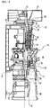
- FIG. 2 is a sectional view partially showing a gas turbine rotor according to an embodiment of the present disclosure
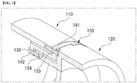
- FIG. 3 is a perspective sectional view of FIG. 2
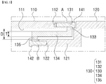
- FIG. 4 is a partial enlarged view of FIG. 3
- FIG. 5 is a partial enlarged view showing a first rotor, a second rotor, and a connecting member according to an embodiment of the present disclosure.
- a gas turbine rotor 100 which rotates with a compressor and a turbine blade mounted to an outer circumferential surface thereof, may include a first rotor 110, a second rotor 120, and a connecting member 130 having predetermined structures.
- the connecting member 130 is made of a material having a thermal expansion coefficient different from that of both the first rotor 110 and the second rotor 120, it is possible to provide a gas turbine rotor and a gas turbine having the same, in which an axial interval between the first rotor 110 and the second rotor 120 is changed by thermal expansion at the start of the gas turbine, so an axial length of the entire gas turbine rotor 100 can be adjusted efficiently, and as a result, a radial clearance of the turbine can be adjusted.
- the first rotor 110 is in a shaft shape extending by a predetermined length in an axial direction, and is provided with an insertion hole 111 at an end thereof to allow an insertion part 121 of the second rotor 120 to be inserted therein.
- the second rotor 120 is formed in a shaft shape extending by a predetermined length in the axial direction, and is provided with the insertion part 121 extending by a predetermined length at an end thereof and corresponding to the insertion hole 111 provided in the first rotor 110. That is, the insertion part 121 is inserted into the insertion hole 111.
- the connecting member 130 is mounted between the insertion hole 111 of the first rotor 110 and the insertion part 121 of the second rotor 120 to connect the first rotor 110 and the second rotor 120 together, and is made of a material having a thermal expansion coefficient different from a thermal expansion coefficient of both the first rotor 110 and the second rotor 120.
- the first rotor 110 and the second rotor 120 are coupled together through the connecting member 130.
- the first rotor 110 is provided with bolt holes 112 at the end thereof along an outer circumferential surface to be spaced apart from each other at predetermined intervals
- the connecting member 130 is provided with through-holes 131 at locations on a side surface thereof corresponding to the bolt holes 112, with the end of the first rotor 110 coupled thereto.
- the first rotor 110 and the connecting member 130 are bolted to each other by using the bolt holes 112 and the through-holes 131.
- the insertion part 121 is provided with bolt holes 122 at an end thereof along an outer circumferential surface to be spaced apart from each other at predetermined intervals
- the connecting member 130 is provided with through-holes 132 at locations on a side surface thereof corresponding to the bolt holes 122, with the end of the insertion part 121 coupled thereto.
- the second rotor 120 and the connecting member 130 are bolted to each other by using the bolt holes 122 and the through-holes 132.
- the connecting member 130 is firmly and stably bolted to both the first rotor 110 and the second rotor 120, so it is possible to achieve a stable structure of the gas turbine rotor 100.
- the connecting member 130 according to the embodiment may be configured such that at least two materials having different thermal expansion coefficients are arranged in a predetermined pattern.
- the pattern may be appropriately changed according to the designer's intention. For example, since the material around the through-holes 131 connected to the first rotor 110 and the material around the through-holes 132 connected to the second rotor 120 are made to have different thermal expansion coefficients, it is possible to differently adjust the length change in the first rotor 110 and the length change in the second rotor 120.
- the radial clearance for the compressor blade may be adjusted to be larger and the radial clearance for the turbine blade may be adjusted smaller.
- the connecting member 130 is made of at least two materials having different thermal expansion coefficients according to purpose and order, it is possible to provide a gas turbine rotor and a gas turbine having the same, in which the axial length of the gas turbine rotor is locally and differently adjusted according to the temperature rise of the gas turbine rotor at the starting phase of the gas turbine, whereby the radial clearance of the turbine can be adjusted.
- the connecting member 130 may include a first connecting part 133, an extension part 134, and a second connecting part 135 having predetermined structures.
- first connecting part 133 and the second connecting part 135 may be integrally provided at opposite ends of the extension part 134 and may be configured to be bent in opposite directions and extend by a predetermined length.
- the extension part 134 integrally connecting the first connecting part 133 and the second connecting part 135 to each other may have a structure corresponding to an outer circumferential surface of the insertion part 121 by extending by a predetermined length.
- an inner circumferential surface of the insertion hole 111 and the outer circumferential surface of the insertion part 121 be spaced apart from each other at a predetermined interval in consideration of a thickness T of the extension part 134.
- an interval D between the inner circumferential surface of the insertion hole 111 and the outer circumferential surface of the insertion part 121 may range from 100% to 110% of the thickness T of the extension part 134.
- the interval D between the inner circumferential surface of the insertion hole 111 and the outer circumferential surface of the insertion part 121 may be appropriately changed in consideration of the kind of the material constituting the connecting member 130 and the interval changed by the thermal expansion.
- the interval between the inner circumferential surface of the insertion hole 111 and the outer circumferential surface of the insertion part 121 is limited to a predetermined range relative to the thickness of the thickness T of the extension part 134, it is possible to more precisely and reliably adjust the entire length of the gas turbine rotor 100 according to the thermal deformation of the connecting member 130.
- the connecting member 130 may have a cross-section in an annular shape having an outer diameter corresponding to outer diameters of the first rotor 110 and the second rotor 120.
- the connecting member 130 constituted by a plurality of pieces may be used to connect the first rotor 110 and the second rotor 120 together.
- the connecting member 130 constituted by a plurality of pieces may be configured such that at least two connecting members are connected to each other to have a cross-section in an annular shape corresponding to outer diameters of the first rotor 110 and the second rotor 120.
- the above embodiment is advantageous in that since the connecting member 130 can be manufactured in a small size and the weight thereof is easy to handle, the efficiency may be remarkably improved in manufacturing a gas turbine rotor.
- extension part 134 may be configured such that at least two materials having different thermal expansion coefficients are arranged in a predetermined pattern.
- the pattern may be appropriately changed according to the designer's intention.
- both a contact surface A between the first rotor 110 and the connecting member 130 and a contact surface B between the second rotor 120 and the connecting member 130 may be coated with a heat transfer material.
- FIG. 6 is an exploded view showing a first rotor 110, a second rotor 120, and a connecting member 130 according to another embodiment of the present disclosure
- FIG. 7 is a partial enlarged view showing a state where the first rotor 110, the second rotor 120, and the connecting member 130 shown in FIG. 6 are assembled.
- first rotor 110 and the second rotor 120 are provided therein with first passages 151 and 153, respectively, to allow cooling fluid to flow therethrough.
- the connecting member 130 is provided therein with a second passage 152 communicating with the first passages 151 and 153.
- the second passage 152 be provided in a direction parallel to an extension direction of the connecting member 130.
- the second passage 152 may be provided in plural and spaced apart from each other at predetermined intervals.
- the gas turbine rotor of the present disclosure since the gas turbine rotor is provided with the first passages 151 and 153, and the second passage 152 having predetermined structures such that the cooling air flows therethrough, it is possible to easily adjust the axial length of the first rotor 110, the second rotor 120, and the connecting member 130 according to the thermal deformation.
- the present disclosure further provides a gas turbine having the above described gas turbine rotor 100, in which the axial length of the gas turbine rotor is adjusted according to the temperature rise of the gas turbine rotor at the starting phase of the gas turbine, thereby adjusting a radial clearance of the turbine.
Landscapes
- Engineering & Computer Science (AREA)
- Mechanical Engineering (AREA)
- General Engineering & Computer Science (AREA)
- Turbine Rotor Nozzle Sealing (AREA)
- Structures Of Non-Positive Displacement Pumps (AREA)
Applications Claiming Priority (1)
| Application Number | Priority Date | Filing Date | Title |
|---|---|---|---|
| KR1020170055165A KR101872808B1 (ko) | 2017-04-28 | 2017-04-28 | 길이조절구조를 포함하는 가스터빈 로터, 및 이를 포함하는 가스터빈 |
Publications (2)
| Publication Number | Publication Date |
|---|---|
| EP3396106A1 true EP3396106A1 (fr) | 2018-10-31 |
| EP3396106B1 EP3396106B1 (fr) | 2019-11-06 |
Family
ID=59966654
Family Applications (1)
| Application Number | Title | Priority Date | Filing Date |
|---|---|---|---|
| EP17192933.4A Active EP3396106B1 (fr) | 2017-04-28 | 2017-09-25 | Rotor de turbine à gaz présentant une structure permettant de régler le jeu axial et turbine à gaz le comprenant |
Country Status (4)
| Country | Link |
|---|---|
| US (2) | US10612417B2 (fr) |
| EP (1) | EP3396106B1 (fr) |
| JP (1) | JP6453407B2 (fr) |
| KR (1) | KR101872808B1 (fr) |
Citations (4)
| Publication number | Priority date | Publication date | Assignee | Title |
|---|---|---|---|---|
| EP1193370A2 (fr) * | 2000-09-29 | 2002-04-03 | General Motors Corporation | Accouplement permettant l'alignement des arbres d'une turbo soufflante |
| WO2013104880A1 (fr) * | 2012-01-10 | 2013-07-18 | Napier Turbochargers Limited | Turbocompresseur présentant un raccord permettant de raccorder un impulseur à un arbre |
| KR101539876B1 (ko) | 2011-03-23 | 2015-07-27 | 미츠비시 히타치 파워 시스템즈 가부시키가이샤 | 터빈 로터 및 터빈 로터의 제조 방법 |
| KR20170015248A (ko) * | 2015-07-30 | 2017-02-08 | 정현욱 | 가스 터빈 엔진의 로터 조립체 |
Family Cites Families (26)
| Publication number | Priority date | Publication date | Assignee | Title |
|---|---|---|---|---|
| BE469282A (fr) * | 1945-11-20 | |||
| FR1012335A (fr) * | 1949-07-13 | 1952-07-08 | Hispano Suiza Sa | Perfectionnements apportés aux engins, notamment aux compresseurs axiaux, à rotor équipé de plusieurs aubages disposés en tandem |
| GB969579A (en) * | 1962-11-09 | 1964-09-09 | Rolls Royce | Gas turbine engine |
| US3304052A (en) * | 1965-03-30 | 1967-02-14 | Westinghouse Electric Corp | Rotor structure for an elastic fluid utilizing machine |
| US3597110A (en) * | 1969-10-23 | 1971-08-03 | Gen Electric | Joint construction |
| JPS5769116A (en) * | 1980-10-17 | 1982-04-27 | Toyo Eng Corp | Flexible coupling |
| US4478593A (en) * | 1981-06-08 | 1984-10-23 | Gordon Brown | Coupling of unrelated engine and transmission |
| JPS58201040A (ja) * | 1982-05-19 | 1983-11-22 | Hitachi Ltd | 複合サイクルプラント軸系の異常診断装置 |
| JPS59169480U (ja) * | 1983-04-28 | 1984-11-13 | 株式会社日立製作所 | 低圧車室用伸縮継手 |
| DE3407275A1 (de) | 1984-02-28 | 1985-08-29 | Kraftwerk Union AG, 4330 Mülheim | Einrichtung an einer rotierenden maschine zur waermebeweglichen und abdichtenden kopplung zweier konzentrischer wellen |
| DE3535511A1 (de) * | 1984-10-06 | 1986-04-17 | Ngk Spark Plug Co., Ltd., Nagoya, Aichi | Verbindungsanordnung zwischen einer keramik- und einer metallwelle |
| JPS631890A (ja) * | 1986-02-14 | 1988-01-06 | 株式会社日立製作所 | 伸縮管継手 |
| DE3815977A1 (de) * | 1988-05-10 | 1989-11-30 | Mtu Muenchen Gmbh | Folienzwischenlage zur fuegung von reibkorrosionsgefaehrdeten maschinenbauteilen |
| US4836750A (en) * | 1988-06-15 | 1989-06-06 | Pratt & Whitney Canada Inc. | Rotor assembly |
| US5203441A (en) * | 1992-06-01 | 1993-04-20 | Eaton Corporation | Adaptor for use in a flywheel and transmission assembly |
| JP3621523B2 (ja) * | 1996-09-25 | 2005-02-16 | 株式会社東芝 | ガスタービンの動翼冷却装置 |
| US6283712B1 (en) * | 1999-09-07 | 2001-09-04 | General Electric Company | Cooling air supply through bolted flange assembly |
| US7255538B2 (en) * | 2005-02-09 | 2007-08-14 | Hamilton Sundstrand Corporation | Shrink-fit stress coupling for a shaft of differing materials |
| EP1744016A1 (fr) * | 2005-07-11 | 2007-01-17 | Siemens Aktiengesellschaft | Elément de carénage pour gaz chauds, chemise de protection de l'arbre et turbine à gaz |
| US7870742B2 (en) * | 2006-11-10 | 2011-01-18 | General Electric Company | Interstage cooled turbine engine |
| US7874156B2 (en) * | 2007-03-29 | 2011-01-25 | General Electric Company | Methods and apparatus for heating a fluid |
| US8251643B2 (en) * | 2009-09-23 | 2012-08-28 | General Electric Company | Steam turbine having rotor with cavities |
| EP2333239A1 (fr) * | 2009-12-08 | 2011-06-15 | Alstom Technology Ltd | Procédé de fabrication d'un rotor de turbine à vapeur et rotor associé |
| AU2013311950B2 (en) * | 2012-09-04 | 2017-04-13 | Hackforth Gmbh | Shaft made of fibre composite material with fireproof bulkhead feedthrough |
| EP2933432A1 (fr) * | 2014-04-15 | 2015-10-21 | Siemens Aktiengesellschaft | Rotor doté d'une bague d'appui bloquée axialement |
| US20150345504A1 (en) * | 2014-05-29 | 2015-12-03 | Siemens Energy, Inc. | Method for forming a coating matrix on a shaft and disk assembly for a turbine |
-
2017
- 2017-04-28 KR KR1020170055165A patent/KR101872808B1/ko active IP Right Grant
- 2017-09-20 JP JP2017180277A patent/JP6453407B2/ja active Active
- 2017-09-25 US US15/714,126 patent/US10612417B2/en active Active
- 2017-09-25 EP EP17192933.4A patent/EP3396106B1/fr active Active
-
2020
- 2020-02-24 US US16/799,794 patent/US11242771B2/en active Active
Patent Citations (4)
| Publication number | Priority date | Publication date | Assignee | Title |
|---|---|---|---|---|
| EP1193370A2 (fr) * | 2000-09-29 | 2002-04-03 | General Motors Corporation | Accouplement permettant l'alignement des arbres d'une turbo soufflante |
| KR101539876B1 (ko) | 2011-03-23 | 2015-07-27 | 미츠비시 히타치 파워 시스템즈 가부시키가이샤 | 터빈 로터 및 터빈 로터의 제조 방법 |
| WO2013104880A1 (fr) * | 2012-01-10 | 2013-07-18 | Napier Turbochargers Limited | Turbocompresseur présentant un raccord permettant de raccorder un impulseur à un arbre |
| KR20170015248A (ko) * | 2015-07-30 | 2017-02-08 | 정현욱 | 가스 터빈 엔진의 로터 조립체 |
Also Published As
| Publication number | Publication date |
|---|---|
| JP6453407B2 (ja) | 2019-01-16 |
| US10612417B2 (en) | 2020-04-07 |
| KR101872808B1 (ko) | 2018-06-29 |
| US20180313229A1 (en) | 2018-11-01 |
| US20200248590A1 (en) | 2020-08-06 |
| JP2018189080A (ja) | 2018-11-29 |
| US11242771B2 (en) | 2022-02-08 |
| EP3396106B1 (fr) | 2019-11-06 |
Similar Documents
| Publication | Publication Date | Title |
|---|---|---|
| EP2230382B1 (fr) | Etage de rotor de turbine à gaz | |
| US9394798B2 (en) | Gas turbine engines with turbine airfoil cooling | |
| EP2578803B1 (fr) | Procédés et systèmes destinés à être utilisés pour la régulation de température de composants | |
| US10352177B2 (en) | Airfoil having impingement openings | |
| US20180328190A1 (en) | Gas turbine engine with film holes | |
| US10605170B2 (en) | Engine component with film cooling | |
| EP3058201B1 (fr) | Paroi de chambre de combustion ayant un ou plusieurs éléments de refroidissement dans une cavité de refroidissement | |
| CA2944392A1 (fr) | Pale de turbine | |
| CA2944464A1 (fr) | Pale de turbine | |
| JP7012452B2 (ja) | スロットの分離が可変のエーロフォイル | |
| EP2713013A1 (fr) | Moteur de turbine à gaz | |
| CA2957481A1 (fr) | Surface portante comportant des trous transversaux | |
| EP3835550B1 (fr) | Aube rotorique pour une turbomachine et turbomachine | |
| US10982547B2 (en) | Compressor having reinforcing disk, and gas turbine having same | |
| CN112943376A (zh) | 用于涡轮机转子叶片的阻尼器堆叠 | |
| JP2004028097A (ja) | タービンブレード壁の冷却装置及び製造方法 | |
| US11242771B2 (en) | Gas turbine rotor having structure for adjusting axial clearance, and gas turbine having same | |
| JP5662672B2 (ja) | タービン翼形部冷却アパーチャに関連する装置 | |
| EP3453831B1 (fr) | Aube comportant des socles profilés | |
| EP3244006A1 (fr) | Arbre et turbo-machine |
Legal Events
| Date | Code | Title | Description |
|---|---|---|---|
| PUAI | Public reference made under article 153(3) epc to a published international application that has entered the european phase |
Free format text: ORIGINAL CODE: 0009012 |
|
| STAA | Information on the status of an ep patent application or granted ep patent |
Free format text: STATUS: REQUEST FOR EXAMINATION WAS MADE |
|
| 17P | Request for examination filed |
Effective date: 20171018 |
|
| AK | Designated contracting states |
Kind code of ref document: A1 Designated state(s): AL AT BE BG CH CY CZ DE DK EE ES FI FR GB GR HR HU IE IS IT LI LT LU LV MC MK MT NL NO PL PT RO RS SE SI SK SM TR |
|
| AX | Request for extension of the european patent |
Extension state: BA ME |
|
| GRAP | Despatch of communication of intention to grant a patent |
Free format text: ORIGINAL CODE: EPIDOSNIGR1 |
|
| RIC1 | Information provided on ipc code assigned before grant |
Ipc: F01D 5/06 20060101AFI20190318BHEP |
|
| STAA | Information on the status of an ep patent application or granted ep patent |
Free format text: STATUS: GRANT OF PATENT IS INTENDED |
|
| INTG | Intention to grant announced |
Effective date: 20190425 |
|
| GRAS | Grant fee paid |
Free format text: ORIGINAL CODE: EPIDOSNIGR3 |
|
| GRAA | (expected) grant |
Free format text: ORIGINAL CODE: 0009210 |
|
| STAA | Information on the status of an ep patent application or granted ep patent |
Free format text: STATUS: THE PATENT HAS BEEN GRANTED |
|
| AK | Designated contracting states |
Kind code of ref document: B1 Designated state(s): AL AT BE BG CH CY CZ DE DK EE ES FI FR GB GR HR HU IE IS IT LI LT LU LV MC MK MT NL NO PL PT RO RS SE SI SK SM TR |
|
| REG | Reference to a national code |
Ref country code: GB Ref legal event code: FG4D |
|
| REG | Reference to a national code |
Ref country code: CH Ref legal event code: EP Ref country code: AT Ref legal event code: REF Ref document number: 1198966 Country of ref document: AT Kind code of ref document: T Effective date: 20191115 |
|
| REG | Reference to a national code |
Ref country code: IE Ref legal event code: FG4D |
|
| REG | Reference to a national code |
Ref country code: DE Ref legal event code: R096 Ref document number: 602017008410 Country of ref document: DE |
|
| REG | Reference to a national code |
Ref country code: NL Ref legal event code: MP Effective date: 20191106 |
|
| REG | Reference to a national code |
Ref country code: LT Ref legal event code: MG4D |
|
| PG25 | Lapsed in a contracting state [announced via postgrant information from national office to epo] |
Ref country code: FI Free format text: LAPSE BECAUSE OF FAILURE TO SUBMIT A TRANSLATION OF THE DESCRIPTION OR TO PAY THE FEE WITHIN THE PRESCRIBED TIME-LIMIT Effective date: 20191106 Ref country code: BG Free format text: LAPSE BECAUSE OF FAILURE TO SUBMIT A TRANSLATION OF THE DESCRIPTION OR TO PAY THE FEE WITHIN THE PRESCRIBED TIME-LIMIT Effective date: 20200206 Ref country code: NL Free format text: LAPSE BECAUSE OF FAILURE TO SUBMIT A TRANSLATION OF THE DESCRIPTION OR TO PAY THE FEE WITHIN THE PRESCRIBED TIME-LIMIT Effective date: 20191106 Ref country code: SE Free format text: LAPSE BECAUSE OF FAILURE TO SUBMIT A TRANSLATION OF THE DESCRIPTION OR TO PAY THE FEE WITHIN THE PRESCRIBED TIME-LIMIT Effective date: 20191106 Ref country code: LV Free format text: LAPSE BECAUSE OF FAILURE TO SUBMIT A TRANSLATION OF THE DESCRIPTION OR TO PAY THE FEE WITHIN THE PRESCRIBED TIME-LIMIT Effective date: 20191106 Ref country code: PL Free format text: LAPSE BECAUSE OF FAILURE TO SUBMIT A TRANSLATION OF THE DESCRIPTION OR TO PAY THE FEE WITHIN THE PRESCRIBED TIME-LIMIT Effective date: 20191106 Ref country code: LT Free format text: LAPSE BECAUSE OF FAILURE TO SUBMIT A TRANSLATION OF THE DESCRIPTION OR TO PAY THE FEE WITHIN THE PRESCRIBED TIME-LIMIT Effective date: 20191106 Ref country code: NO Free format text: LAPSE BECAUSE OF FAILURE TO SUBMIT A TRANSLATION OF THE DESCRIPTION OR TO PAY THE FEE WITHIN THE PRESCRIBED TIME-LIMIT Effective date: 20200206 Ref country code: PT Free format text: LAPSE BECAUSE OF FAILURE TO SUBMIT A TRANSLATION OF THE DESCRIPTION OR TO PAY THE FEE WITHIN THE PRESCRIBED TIME-LIMIT Effective date: 20200306 Ref country code: GR Free format text: LAPSE BECAUSE OF FAILURE TO SUBMIT A TRANSLATION OF THE DESCRIPTION OR TO PAY THE FEE WITHIN THE PRESCRIBED TIME-LIMIT Effective date: 20200207 |
|
| PG25 | Lapsed in a contracting state [announced via postgrant information from national office to epo] |
Ref country code: IS Free format text: LAPSE BECAUSE OF FAILURE TO SUBMIT A TRANSLATION OF THE DESCRIPTION OR TO PAY THE FEE WITHIN THE PRESCRIBED TIME-LIMIT Effective date: 20200306 Ref country code: HR Free format text: LAPSE BECAUSE OF FAILURE TO SUBMIT A TRANSLATION OF THE DESCRIPTION OR TO PAY THE FEE WITHIN THE PRESCRIBED TIME-LIMIT Effective date: 20191106 Ref country code: RS Free format text: LAPSE BECAUSE OF FAILURE TO SUBMIT A TRANSLATION OF THE DESCRIPTION OR TO PAY THE FEE WITHIN THE PRESCRIBED TIME-LIMIT Effective date: 20191106 |
|
| PG25 | Lapsed in a contracting state [announced via postgrant information from national office to epo] |
Ref country code: AL Free format text: LAPSE BECAUSE OF FAILURE TO SUBMIT A TRANSLATION OF THE DESCRIPTION OR TO PAY THE FEE WITHIN THE PRESCRIBED TIME-LIMIT Effective date: 20191106 |
|
| PG25 | Lapsed in a contracting state [announced via postgrant information from national office to epo] |
Ref country code: DK Free format text: LAPSE BECAUSE OF FAILURE TO SUBMIT A TRANSLATION OF THE DESCRIPTION OR TO PAY THE FEE WITHIN THE PRESCRIBED TIME-LIMIT Effective date: 20191106 Ref country code: EE Free format text: LAPSE BECAUSE OF FAILURE TO SUBMIT A TRANSLATION OF THE DESCRIPTION OR TO PAY THE FEE WITHIN THE PRESCRIBED TIME-LIMIT Effective date: 20191106 Ref country code: ES Free format text: LAPSE BECAUSE OF FAILURE TO SUBMIT A TRANSLATION OF THE DESCRIPTION OR TO PAY THE FEE WITHIN THE PRESCRIBED TIME-LIMIT Effective date: 20191106 Ref country code: CZ Free format text: LAPSE BECAUSE OF FAILURE TO SUBMIT A TRANSLATION OF THE DESCRIPTION OR TO PAY THE FEE WITHIN THE PRESCRIBED TIME-LIMIT Effective date: 20191106 Ref country code: RO Free format text: LAPSE BECAUSE OF FAILURE TO SUBMIT A TRANSLATION OF THE DESCRIPTION OR TO PAY THE FEE WITHIN THE PRESCRIBED TIME-LIMIT Effective date: 20191106 |
|
| REG | Reference to a national code |
Ref country code: DE Ref legal event code: R097 Ref document number: 602017008410 Country of ref document: DE |
|
| REG | Reference to a national code |
Ref country code: AT Ref legal event code: MK05 Ref document number: 1198966 Country of ref document: AT Kind code of ref document: T Effective date: 20191106 |
|
| PG25 | Lapsed in a contracting state [announced via postgrant information from national office to epo] |
Ref country code: SK Free format text: LAPSE BECAUSE OF FAILURE TO SUBMIT A TRANSLATION OF THE DESCRIPTION OR TO PAY THE FEE WITHIN THE PRESCRIBED TIME-LIMIT Effective date: 20191106 Ref country code: SM Free format text: LAPSE BECAUSE OF FAILURE TO SUBMIT A TRANSLATION OF THE DESCRIPTION OR TO PAY THE FEE WITHIN THE PRESCRIBED TIME-LIMIT Effective date: 20191106 |
|
| PLBE | No opposition filed within time limit |
Free format text: ORIGINAL CODE: 0009261 |
|
| STAA | Information on the status of an ep patent application or granted ep patent |
Free format text: STATUS: NO OPPOSITION FILED WITHIN TIME LIMIT |
|
| 26N | No opposition filed |
Effective date: 20200807 |
|
| PG25 | Lapsed in a contracting state [announced via postgrant information from national office to epo] |
Ref country code: AT Free format text: LAPSE BECAUSE OF FAILURE TO SUBMIT A TRANSLATION OF THE DESCRIPTION OR TO PAY THE FEE WITHIN THE PRESCRIBED TIME-LIMIT Effective date: 20191106 Ref country code: SI Free format text: LAPSE BECAUSE OF FAILURE TO SUBMIT A TRANSLATION OF THE DESCRIPTION OR TO PAY THE FEE WITHIN THE PRESCRIBED TIME-LIMIT Effective date: 20191106 |
|
| PG25 | Lapsed in a contracting state [announced via postgrant information from national office to epo] |
Ref country code: IT Free format text: LAPSE BECAUSE OF FAILURE TO SUBMIT A TRANSLATION OF THE DESCRIPTION OR TO PAY THE FEE WITHIN THE PRESCRIBED TIME-LIMIT Effective date: 20191106 |
|
| REG | Reference to a national code |
Ref country code: CH Ref legal event code: PL |
|
| REG | Reference to a national code |
Ref country code: BE Ref legal event code: MM Effective date: 20200930 |
|
| PG25 | Lapsed in a contracting state [announced via postgrant information from national office to epo] |
Ref country code: LU Free format text: LAPSE BECAUSE OF NON-PAYMENT OF DUE FEES Effective date: 20200925 |
|
| PG25 | Lapsed in a contracting state [announced via postgrant information from national office to epo] |
Ref country code: FR Free format text: LAPSE BECAUSE OF NON-PAYMENT OF DUE FEES Effective date: 20200930 |
|
| PG25 | Lapsed in a contracting state [announced via postgrant information from national office to epo] |
Ref country code: IE Free format text: LAPSE BECAUSE OF NON-PAYMENT OF DUE FEES Effective date: 20200925 Ref country code: LI Free format text: LAPSE BECAUSE OF NON-PAYMENT OF DUE FEES Effective date: 20200930 Ref country code: CH Free format text: LAPSE BECAUSE OF NON-PAYMENT OF DUE FEES Effective date: 20200930 Ref country code: BE Free format text: LAPSE BECAUSE OF NON-PAYMENT OF DUE FEES Effective date: 20200930 |
|
| GBPC | Gb: european patent ceased through non-payment of renewal fee |
Effective date: 20210925 |
|
| PG25 | Lapsed in a contracting state [announced via postgrant information from national office to epo] |
Ref country code: TR Free format text: LAPSE BECAUSE OF FAILURE TO SUBMIT A TRANSLATION OF THE DESCRIPTION OR TO PAY THE FEE WITHIN THE PRESCRIBED TIME-LIMIT Effective date: 20191106 Ref country code: MT Free format text: LAPSE BECAUSE OF FAILURE TO SUBMIT A TRANSLATION OF THE DESCRIPTION OR TO PAY THE FEE WITHIN THE PRESCRIBED TIME-LIMIT Effective date: 20191106 Ref country code: CY Free format text: LAPSE BECAUSE OF FAILURE TO SUBMIT A TRANSLATION OF THE DESCRIPTION OR TO PAY THE FEE WITHIN THE PRESCRIBED TIME-LIMIT Effective date: 20191106 |
|
| PG25 | Lapsed in a contracting state [announced via postgrant information from national office to epo] |
Ref country code: MK Free format text: LAPSE BECAUSE OF FAILURE TO SUBMIT A TRANSLATION OF THE DESCRIPTION OR TO PAY THE FEE WITHIN THE PRESCRIBED TIME-LIMIT Effective date: 20191106 Ref country code: MC Free format text: LAPSE BECAUSE OF FAILURE TO SUBMIT A TRANSLATION OF THE DESCRIPTION OR TO PAY THE FEE WITHIN THE PRESCRIBED TIME-LIMIT Effective date: 20191106 |
|
| PG25 | Lapsed in a contracting state [announced via postgrant information from national office to epo] |
Ref country code: GB Free format text: LAPSE BECAUSE OF NON-PAYMENT OF DUE FEES Effective date: 20210925 |
|
| PGFP | Annual fee paid to national office [announced via postgrant information from national office to epo] |
Ref country code: DE Payment date: 20230802 Year of fee payment: 7 |