EP3395640A1 - Drehgestell eines schienenfahrzeugs, das ein bremssystem mit drei bremsscheiben umfasst, die zwischen den den achsengehäusen angeordnet sind - Google Patents
Drehgestell eines schienenfahrzeugs, das ein bremssystem mit drei bremsscheiben umfasst, die zwischen den den achsengehäusen angeordnet sind Download PDFInfo
- Publication number
- EP3395640A1 EP3395640A1 EP18153077.5A EP18153077A EP3395640A1 EP 3395640 A1 EP3395640 A1 EP 3395640A1 EP 18153077 A EP18153077 A EP 18153077A EP 3395640 A1 EP3395640 A1 EP 3395640A1
- Authority
- EP
- European Patent Office
- Prior art keywords
- axle
- braking
- bogie
- pair
- brake
- Prior art date
- Legal status (The legal status is an assumption and is not a legal conclusion. Google has not performed a legal analysis and makes no representation as to the accuracy of the status listed.)
- Granted
Links
- 230000010354 integration Effects 0.000 description 1
- 239000000725 suspension Substances 0.000 description 1
Images


Classifications
-
- F—MECHANICAL ENGINEERING; LIGHTING; HEATING; WEAPONS; BLASTING
- F16—ENGINEERING ELEMENTS AND UNITS; GENERAL MEASURES FOR PRODUCING AND MAINTAINING EFFECTIVE FUNCTIONING OF MACHINES OR INSTALLATIONS; THERMAL INSULATION IN GENERAL
- F16D—COUPLINGS FOR TRANSMITTING ROTATION; CLUTCHES; BRAKES
- F16D55/00—Brakes with substantially-radial braking surfaces pressed together in axial direction, e.g. disc brakes
- F16D55/02—Brakes with substantially-radial braking surfaces pressed together in axial direction, e.g. disc brakes with axially-movable discs or pads pressed against axially-located rotating members
- F16D55/22—Brakes with substantially-radial braking surfaces pressed together in axial direction, e.g. disc brakes with axially-movable discs or pads pressed against axially-located rotating members by clamping an axially-located rotating disc between movable braking members, e.g. movable brake discs or brake pads
- F16D55/224—Brakes with substantially-radial braking surfaces pressed together in axial direction, e.g. disc brakes with axially-movable discs or pads pressed against axially-located rotating members by clamping an axially-located rotating disc between movable braking members, e.g. movable brake discs or brake pads with a common actuating member for the braking members
- F16D55/2245—Brakes with substantially-radial braking surfaces pressed together in axial direction, e.g. disc brakes with axially-movable discs or pads pressed against axially-located rotating members by clamping an axially-located rotating disc between movable braking members, e.g. movable brake discs or brake pads with a common actuating member for the braking members in which the common actuating member acts on two levers carrying the braking members, e.g. tong-type brakes
-
- B—PERFORMING OPERATIONS; TRANSPORTING
- B61—RAILWAYS
- B61H—BRAKES OR OTHER RETARDING DEVICES SPECIALLY ADAPTED FOR RAIL VEHICLES; ARRANGEMENT OR DISPOSITION THEREOF IN RAIL VEHICLES
- B61H1/00—Applications or arrangements of brakes with a braking member or members co-operating with the periphery of the wheel rim, a drum, or the like
-
- B—PERFORMING OPERATIONS; TRANSPORTING
- B60—VEHICLES IN GENERAL
- B60T—VEHICLE BRAKE CONTROL SYSTEMS OR PARTS THEREOF; BRAKE CONTROL SYSTEMS OR PARTS THEREOF, IN GENERAL; ARRANGEMENT OF BRAKING ELEMENTS ON VEHICLES IN GENERAL; PORTABLE DEVICES FOR PREVENTING UNWANTED MOVEMENT OF VEHICLES; VEHICLE MODIFICATIONS TO FACILITATE COOLING OF BRAKES
- B60T1/00—Arrangements of braking elements, i.e. of those parts where braking effect occurs specially for vehicles
- B60T1/02—Arrangements of braking elements, i.e. of those parts where braking effect occurs specially for vehicles acting by retarding wheels
- B60T1/06—Arrangements of braking elements, i.e. of those parts where braking effect occurs specially for vehicles acting by retarding wheels acting otherwise than on tread, e.g. employing rim, drum, disc, or transmission or on double wheels
- B60T1/062—Arrangements of braking elements, i.e. of those parts where braking effect occurs specially for vehicles acting by retarding wheels acting otherwise than on tread, e.g. employing rim, drum, disc, or transmission or on double wheels acting on transmission parts
-
- B—PERFORMING OPERATIONS; TRANSPORTING
- B61—RAILWAYS
- B61F—RAIL VEHICLE SUSPENSIONS, e.g. UNDERFRAMES, BOGIES OR ARRANGEMENTS OF WHEEL AXLES; RAIL VEHICLES FOR USE ON TRACKS OF DIFFERENT WIDTH; PREVENTING DERAILING OF RAIL VEHICLES; WHEEL GUARDS, OBSTRUCTION REMOVERS OR THE LIKE FOR RAIL VEHICLES
- B61F3/00—Types of bogies
- B61F3/02—Types of bogies with more than one axle
-
- B—PERFORMING OPERATIONS; TRANSPORTING
- B61—RAILWAYS
- B61F—RAIL VEHICLE SUSPENSIONS, e.g. UNDERFRAMES, BOGIES OR ARRANGEMENTS OF WHEEL AXLES; RAIL VEHICLES FOR USE ON TRACKS OF DIFFERENT WIDTH; PREVENTING DERAILING OF RAIL VEHICLES; WHEEL GUARDS, OBSTRUCTION REMOVERS OR THE LIKE FOR RAIL VEHICLES
- B61F5/00—Constructional details of bogies; Connections between bogies and vehicle underframes; Arrangements or devices for adjusting or allowing self-adjustment of wheel axles or bogies when rounding curves
- B61F5/26—Mounting or securing axle-boxes in vehicle or bogie underframes
-
- B—PERFORMING OPERATIONS; TRANSPORTING
- B61—RAILWAYS
- B61H—BRAKES OR OTHER RETARDING DEVICES SPECIALLY ADAPTED FOR RAIL VEHICLES; ARRANGEMENT OR DISPOSITION THEREOF IN RAIL VEHICLES
- B61H13/00—Actuating rail vehicle brakes
- B61H13/34—Details
- B61H13/36—Beams; Suspension thereof
-
- B—PERFORMING OPERATIONS; TRANSPORTING
- B61—RAILWAYS
- B61H—BRAKES OR OTHER RETARDING DEVICES SPECIALLY ADAPTED FOR RAIL VEHICLES; ARRANGEMENT OR DISPOSITION THEREOF IN RAIL VEHICLES
- B61H5/00—Applications or arrangements of brakes with substantially radial braking surfaces pressed together in axial direction, e.g. disc brakes
Definitions
- the invention applies to any type of railway vehicle, but is more particularly suitable for trains with very high speeds, for example designed to travel to speeds above 250 km / h.
- This type of brake system further comprises for each brake disc a brake fork whose arms pass around the brake disc so as to act on the faces of the disc during braking.
- this solution also involves the use of different forks and / or a different arrangement of forks for the brake discs mounted on the wheels and for the disc arranged on the axle between the two wheels.
- One of the aims of the invention is to overcome these disadvantages by proposing a bogie comprising at least three brake disks and corresponding forks, in particular identical ones, mounted on the axle between the wheels and allowing integration of the axle boxes. at a transverse end of the axle between the two wheels and the end brake discs.
- the invention relates to a bogie of the aforementioned type, wherein the first ends of the arms all extend on the same side of the axis of rotation of the axle.
- the forks extend two by two in alternately different parallel planes, and on either side of the axis of rotation of the axle.
- These planes may be planes parallel to the longitudinal direction or planes perpendicular to the longitudinal direction.
- the invention further relates to a railway vehicle comprising the bogie described above.
- the term “longitudinal” is defined with respect to the direction of movement of a railway vehicle on rails.
- the term “transverse” is defined in a direction perpendicular to the longitudinal direction and corresponds to the direction in which the rails are spaced.
- the term “elevation” is defined in a direction perpendicular to the longitudinal direction and the transverse direction. When the railway vehicle is traveling on horizontal rails, the longitudinal and transverse directions are substantially horizontal and the direction of elevation is substantially vertical.
- the terms “below”, “above”, “up”, and “down” are defined relative to the elevation direction.
- a railway vehicle bogie 4 comprises a chassis 6 extending substantially substantially in the longitudinal direction and carrying at each of its longitudinal end portions an axle 8 extending substantially in a transverse direction.
- Each axle 8 is rotatably mounted along a transverse axis of rotation A.
- Each of the axles 8 comprises a transversely extending shaft 8a and two wheels 10 fixed to the transverse end portions of the shaft 8a and integral in rotation with it.
- each axle 8 is rotatably mounted in two axle boxes 12 or pair of axle boxes extending around the axle 8, between the two wheels 10.
- Each axle box 12 is formed of a molded body comprising a transverse axis orifice, for example provided with ball bearings, inside which the axle 8 is mounted in rotation.
- the frame 6 comprises two longitudinal members 14 extending substantially longitudinally, only a portion of which is shown in FIG. figure 1 , each connecting one of the axle boxes 12 of a pair to one of the axle boxes of the other pair of axle boxes 12.
- the longitudinal members 14 are for example connected to one another. another by two cross members 16 extending substantially transversely. Only one cross member 16 is shown on the figure 1 .
- the bogie 4 further comprises a braking system 18 which will be described later, mounted around each axle 8.
- each wheel 10 could be rotatably mounted in an axle box 12 independently of the others.
- the bogie 4 could comprise more than two longitudinal members, for example articulated between them.
- the longitudinal members 14 could be interconnected by a central cross member.
- the wheels 10 have been shown to extend outside the bogie 4, but could be disposed therein.
- the chassis 6 could be formed by two half-frames hinged together and each carrying one of the axles 8 of the bogie 4.
- the bogie 4 may be motorized or not, that is to say that it may or may not comprise one or more motors for rotating one or both axles 8 of the bogie 4.
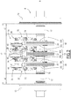
- each axle box 12 has a transverse size d2 substantially equal to 280 mm.
- the space available at the center of the axle 8, so as to integrate the braking system 18, has a length d3 substantially equal to 800 mm.
- the braking system 18 is adapted to be integrated in the space defined between the two axle boxes 12, defined on the figure 2 by the transversal size d3.
- the braking system 18 comprises at least three brake disks 20, 22, 24 mounted around the axle 8, and more particularly around the shaft 8a of the axle 8, in the space defined between the two wheels 10 .
- the braking system 18 further comprises three brake forks 26, 28, 30 respectively acting on the brake disks 20, 22, 24.
- the brake disks 20, 22, 24 are arranged in the space defined between the two axle boxes 12.
- each axle box 12 is mounted on a transverse end of the axle 8 between a wheel 10 and a brake disk 20, 24, the axle 8 being rotatable in the axle boxes 12.
- Each braking fork 26, 28, 30 comprises a pair of arms 32, 34, 36 each extending between a first end and a second end, the second ends each carrying a braking pad 38a, 38b, 40a, 40b, 42a , 42b forming pairs of braking pads 38, 40, 42.
- each braking fork 26, 28, 30 comprises two arms and two braking pads each carried by the second end of the arms.
- each of the pairs of arms 32, 34, 36 are connected to an actuating device, in this example a piston 44, 46, 48, making it possible to vary the spacing between the arms of a pair of arms.
- an actuating device in this example a piston 44, 46, 48, making it possible to vary the spacing between the arms of a pair of arms.
- 32, 34, 36 between an active braking position in which the pair of braking pad 38, 40, 42 is applied against and encloses a portion of the brake disk 20, 22, 24, and an inactive position in which the pair brake pad 38, 40, 42 is spaced from the brake disk 20, 22, 24.
- the pairs of arms 32, 34, 36 are in the active braking position. In this position, the brake forks 26, 28, 30 brake the rotation of the axle 8, and therefore brake the bogie 4.
- the brake forks 26, 28, 30 comprise, in a manner known per se, brake supports 50, 52, 54 adapted to support the arms of a pair of arms 32, 34, 36.
- the braking pads 38a, 38b, 40a, 40b, 42a, 42b are arranged to grip a central surface of the brake disc 20, 22, 24, extending around the axis of rotation A.
- the pairs of shoes 38 and 42 which respectively enclose the central surfaces of the brake discs 20 and 24, extending around the axis of rotation A.
- the braking pad 40b which encloses a surface
- the central surfaces of a brake disk 20, 22, 24 are, for example, substantially facing each other with respect to a plane perpendicular to the axis of rotation A, passing respectively by the brake disk 20, 22, 24.
- the pairs of successive shoes 38, 40 and 42 are alternately arranged on either side of the axis of rotation A in the direction of elevation.
- pairs of braking pads 38, 40, 42 are alternately arranged below and above the axis of rotation A.
- the braking system 18 extends in the longitudinal direction.
- the first pair of shoe 38 is disposed above the axis of rotation A and encloses a central surface of the brake disc 20 located above the axis A.
- the second pair of shoe 40 which follows the first pair of shoes 38 in the transverse direction, is disposed below the axis of rotation A, and encloses a central surface of the brake disc 22 located below the axis of rotation A.
- the third pair of pads 42 which follows the second pair 40 in the transverse direction, is disposed above the axis of rotation A and encloses a central surface of the brake disc 24 located above the axis of rotation A.
- each of the first ends of the arms extend all on the same side of the axis of rotation A.
- the pistons 44, 46, 48 to which are connected the first ends of the arms all extend on the same side of the axis of rotation A.
- the first ends of the arms extend between the two axles 8 of the bogie 4. In other words, the first ends of the arms extend inside the chassis 6.
- the arms associated with the braking pads 38b and 40a, and the arms associated with the braking pads 40b and 42a extend opposite one another in a plane perpendicular to the axis of rotation A.
- the frame 6 comprises a mounting beam 56 or crosses for mounting the brake forks 26, 28, 30 of the braking system 18 in the bogie 4.
- the beam 56 has substantially the shape of a "T".
- the beam 56 comprises a first beam portion extending substantially transversely between the longitudinal members 14, and a second beam portion extending substantially in the downward direction of elevation, from the center of the first beam portion.
- the beam 56 is fixed at its distal ends to the longitudinal members 14 of the frame 6.
- the brake forks 26, 28, 30 are mounted on the mounting beam 56. More particularly, the brake forks 26, 28, 30 are mounted on a lower face of the mounting beam 56, via a fixing device.
- the fixing device comprises, for each brake fork 26, 28, 30, two mounting lugs, integral with an upper portion of a brake support 50, 52, 54 and a lower face of the beam 56.
- the mounting tabs associated with the fork 26 are identified on the figure 1 by references 58 and 60. Other types of fastening system could of course be suitable.
- the adjacent brake forks 26 and 28, and 28 and 30 are attached to the beam 56 at different heights. Indeed, the brake fork 28 is fixed below the brake forks 26 and 30 in the elevation direction.
- the braking system 18 according to the invention described above is more compact than the known braking systems.
- the braking pad pairs 38, 42 are disposed below the axis of rotation A and enclose the surfaces respectively.
- the braking system 18 extends in the direction of elevation, the pairs of arms 32, 34, 36 extending in the direction of elevation.
- the pairs of braking pads 38, 40, 42 and the corresponding braking surfaces of the brake disks 20, 22, 24 are alternately arranged on one side and then on the other side of the axle. rotation A, in the longitudinal direction.
- the pairs of braking pads 38, 40, 42 are alternately arranged outside and inside the frame 6.
- the first pair of shoe 38 is disposed on one side of the axis of rotation A and encloses a central surface of the brake disc 20 located outside the frame 6.
- the second pair of shoe 40 which follows the first pair of shoe 38 in the transverse direction, is disposed on another side of the axis of rotation, and encloses a central surface of the brake disc 22 located inside the frame.
- the third pair of shoes 42 which follows the second pair 40, in the transverse direction, is disposed on the same side of the axis of rotation A as the first pair of braking pads 38 and encloses a central surface of the brake disc located at the outside of the chassis.
- pairs of arms 32, 34, 36 are then all disposed above the axis of rotation A.
Landscapes
- Engineering & Computer Science (AREA)
- Mechanical Engineering (AREA)
- General Engineering & Computer Science (AREA)
- Transportation (AREA)
- Braking Arrangements (AREA)
Priority Applications (1)
| Application Number | Priority Date | Filing Date | Title |
|---|---|---|---|
| PL18153077T PL3395640T3 (pl) | 2017-01-24 | 2018-01-23 | Wózek pojazdu szynowego zawierający układ hamulcowy złożony z trzech tarcz hamulcowych umieszczonych między maźnicami |
Applications Claiming Priority (1)
| Application Number | Priority Date | Filing Date | Title |
|---|---|---|---|
| FR1750571A FR3062113B1 (fr) | 2017-01-24 | 2017-01-24 | Bogie de vehicule ferroviaire comportant un systeme de freinage comprenant trois disques de frein agences entre les boites d'essieu. |
Publications (2)
| Publication Number | Publication Date |
|---|---|
| EP3395640A1 true EP3395640A1 (de) | 2018-10-31 |
| EP3395640B1 EP3395640B1 (de) | 2019-09-25 |
Family
ID=58455286
Family Applications (1)
| Application Number | Title | Priority Date | Filing Date |
|---|---|---|---|
| EP18153077.5A Active EP3395640B1 (de) | 2017-01-24 | 2018-01-23 | Drehgestell eines schienenfahrzeugs, das ein bremssystem mit drei bremsscheiben umfasst, die zwischen den achsengehäusen angeordnet sind |
Country Status (7)
| Country | Link |
|---|---|
| US (1) | US10859132B2 (de) |
| EP (1) | EP3395640B1 (de) |
| CN (1) | CN108340939B (de) |
| ES (1) | ES2763145T3 (de) |
| FR (1) | FR3062113B1 (de) |
| PL (1) | PL3395640T3 (de) |
| RU (1) | RU2750347C2 (de) |
Families Citing this family (1)
| Publication number | Priority date | Publication date | Assignee | Title |
|---|---|---|---|---|
| EP4261089A1 (de) * | 2022-04-12 | 2023-10-18 | Dellner Bubenzer AB | Bremssystem für ein schienenfahrzeug |
Citations (3)
| Publication number | Priority date | Publication date | Assignee | Title |
|---|---|---|---|---|
| US2673623A (en) * | 1951-04-04 | 1954-03-30 | Budd Co | Disk brake unit for association with clasp brake trucks |
| DE19821688A1 (de) * | 1998-05-14 | 1999-11-18 | Sab Wabco Bsi Verkehrstechnik | Bremsanordnung für Schienenfahrzeuge |
| WO2015071254A1 (de) * | 2013-11-13 | 2015-05-21 | Siemens Ag Österreich | Vorrichtung zur reduktion von schwingungen eines fahrzeuges, insbesondere eines schienenfahrzeuges |
Family Cites Families (6)
| Publication number | Priority date | Publication date | Assignee | Title |
|---|---|---|---|---|
| DE3620745A1 (de) * | 1986-06-20 | 1987-12-23 | Linke Hofmann Busch | Scheibenbremseinrichtung fuer schienenfahrzeuge mit drei bremsscheiben auf einer radsatzwelle |
| DE3717303A1 (de) * | 1987-05-22 | 1988-12-15 | Knorr Bremse Ag | Scheibenbremse fuer schienenfahrzeuge |
| ATE213473T1 (de) * | 1995-05-05 | 2002-03-15 | Goodrich Co B F | Bremsvorrichtung und verfahren zum herstellen einer mehr konstanten bremskraft |
| RU2452636C1 (ru) * | 2011-01-12 | 2012-06-10 | Василий Васильевич Лещенко | Дисковый электромеханический тормоз |
| CN203593001U (zh) * | 2013-12-13 | 2014-05-14 | 齐齐哈尔轨道交通装备有限责任公司 | 一种高速铁路货车转向架 |
| CN203580981U (zh) * | 2013-12-13 | 2014-05-07 | 齐齐哈尔轨道交通装备有限责任公司 | 一种铁路货车转向架及其构架 |
-
2017
- 2017-01-24 FR FR1750571A patent/FR3062113B1/fr not_active Expired - Fee Related
-
2018
- 2018-01-23 RU RU2018102557A patent/RU2750347C2/ru active
- 2018-01-23 EP EP18153077.5A patent/EP3395640B1/de active Active
- 2018-01-23 US US15/877,604 patent/US10859132B2/en active Active
- 2018-01-23 ES ES18153077T patent/ES2763145T3/es active Active
- 2018-01-23 CN CN201810064897.2A patent/CN108340939B/zh active Active
- 2018-01-23 PL PL18153077T patent/PL3395640T3/pl unknown
Patent Citations (3)
| Publication number | Priority date | Publication date | Assignee | Title |
|---|---|---|---|---|
| US2673623A (en) * | 1951-04-04 | 1954-03-30 | Budd Co | Disk brake unit for association with clasp brake trucks |
| DE19821688A1 (de) * | 1998-05-14 | 1999-11-18 | Sab Wabco Bsi Verkehrstechnik | Bremsanordnung für Schienenfahrzeuge |
| WO2015071254A1 (de) * | 2013-11-13 | 2015-05-21 | Siemens Ag Österreich | Vorrichtung zur reduktion von schwingungen eines fahrzeuges, insbesondere eines schienenfahrzeuges |
Also Published As
| Publication number | Publication date |
|---|---|
| ES2763145T3 (es) | 2020-05-27 |
| EP3395640B1 (de) | 2019-09-25 |
| RU2750347C2 (ru) | 2021-06-28 |
| US10859132B2 (en) | 2020-12-08 |
| RU2018102557A (ru) | 2019-07-23 |
| US20180209494A1 (en) | 2018-07-26 |
| FR3062113B1 (fr) | 2019-04-05 |
| RU2018102557A3 (de) | 2021-05-19 |
| PL3395640T3 (pl) | 2020-04-30 |
| CN108340939B (zh) | 2021-04-13 |
| FR3062113A1 (fr) | 2018-07-27 |
| CN108340939A (zh) | 2018-07-31 |
Similar Documents
| Publication | Publication Date | Title |
|---|---|---|
| EP3650304B1 (de) | Drehgestell für schienenfahrzeug | |
| EP2455269B1 (de) | Fahrgestell eines Schienenfahrzeugs, das über eine Wirbelstrom-Bremsvorrichtung verfügt | |
| FR2785852A1 (fr) | Ensemble comportant une roue et une suspension integree a la roue | |
| FR2914609A1 (fr) | Bogie pour vehicule ferroviaire | |
| FR2763284A1 (fr) | Ensemble comportant une roue et une suspension integree a la roue | |
| WO2004058521A1 (fr) | Dispositif de support de roue a triple charnière, dispositif de suspension et véhicule comprenant ledit dispositif de support | |
| EP3222485B1 (de) | Schienenfahrzeugdrehgestell, das eine versetzte primäre federungsvorrichtung umfasst | |
| EP2883776A1 (de) | Angetriebenes Drehgestell und Fahrzeug mit einem solchen Drehgestell | |
| FR2707926A1 (fr) | Dispositif de suspension perfectionné pour une roue avant de véhicule automobile. | |
| EP3395640B1 (de) | Drehgestell eines schienenfahrzeugs, das ein bremssystem mit drei bremsscheiben umfasst, die zwischen den achsengehäusen angeordnet sind | |
| EP0489638B1 (de) | Aufhängungsvorrichtung, insbesondere für gelenktes Rad eines Kraftfahrzeugs | |
| FR2822780A1 (fr) | Bogie pour vehicules ferroviaires a roues a ecartement variable | |
| EP1116634B1 (de) | Triebdrehgestell für ein Schienenfahrzeug und Schienenfahrzeug mit solch einem Drehgestell | |
| FR3064590A1 (fr) | Vehicule pendulaire a organes de blocage d'inclinaison | |
| EP3222486B1 (de) | Schienenfahrzeugdrehgestell, das ein abgesenktes fahrgestell umfasst | |
| FR3035028A1 (fr) | "ensemble de train arriere roulant integrant un moteur semi-porteur pour vehicule automobile" | |
| EP3854655B1 (de) | Drehgestell für ein fahrzeug mit unabhängigen rädern und entsprechendes fahrzeug | |
| FR2621277A1 (fr) | Essieu a roues independantes | |
| FR3049252A1 (fr) | Bogie comprenant une liaison rigide entre les boites d'essieu, et vehicule ferroviaire associe | |
| EP3042821B1 (de) | Drehgestell, das eine zentralisierte primärfederung umfasst | |
| EP3521125A1 (de) | Fahrgestell für schienenfahrzeug | |
| FR2750925A1 (fr) | Suspension horizontale pour roue de vehicule automobile avec systeme de filtrage des chocs longitudinaux | |
| EP0501856B1 (de) | Bremsanlage für ein Schienentriebfahrzeug | |
| FR2777224A1 (fr) | Bras de suspension anti-percussion | |
| EP0799144B1 (de) | Bremsvorrichtung für schienenfahrzeug |
Legal Events
| Date | Code | Title | Description |
|---|---|---|---|
| PUAI | Public reference made under article 153(3) epc to a published international application that has entered the european phase |
Free format text: ORIGINAL CODE: 0009012 |
|
| STAA | Information on the status of an ep patent application or granted ep patent |
Free format text: STATUS: THE APPLICATION HAS BEEN PUBLISHED |
|
| AK | Designated contracting states |
Kind code of ref document: A1 Designated state(s): AL AT BE BG CH CY CZ DE DK EE ES FI FR GB GR HR HU IE IS IT LI LT LU LV MC MK MT NL NO PL PT RO RS SE SI SK SM TR |
|
| AX | Request for extension of the european patent |
Extension state: BA ME |
|
| STAA | Information on the status of an ep patent application or granted ep patent |
Free format text: STATUS: REQUEST FOR EXAMINATION WAS MADE |
|
| 17P | Request for examination filed |
Effective date: 20190401 |
|
| GRAP | Despatch of communication of intention to grant a patent |
Free format text: ORIGINAL CODE: EPIDOSNIGR1 |
|
| RBV | Designated contracting states (corrected) |
Designated state(s): AL AT BE BG CH CY CZ DE DK EE ES FI FR GB GR HR HU IE IS IT LI LT LU LV MC MK MT NL NO PL PT RO RS SE SI SK SM TR |
|
| STAA | Information on the status of an ep patent application or granted ep patent |
Free format text: STATUS: GRANT OF PATENT IS INTENDED |
|
| INTG | Intention to grant announced |
Effective date: 20190509 |
|
| GRAS | Grant fee paid |
Free format text: ORIGINAL CODE: EPIDOSNIGR3 |
|
| GRAA | (expected) grant |
Free format text: ORIGINAL CODE: 0009210 |
|
| STAA | Information on the status of an ep patent application or granted ep patent |
Free format text: STATUS: THE PATENT HAS BEEN GRANTED |
|
| AK | Designated contracting states |
Kind code of ref document: B1 Designated state(s): AL AT BE BG CH CY CZ DE DK EE ES FI FR GB GR HR HU IE IS IT LI LT LU LV MC MK MT NL NO PL PT RO RS SE SI SK SM TR |
|
| REG | Reference to a national code |
Ref country code: GB Ref legal event code: FG4D Free format text: NOT ENGLISH |
|
| REG | Reference to a national code |
Ref country code: CH Ref legal event code: EP |
|
| REG | Reference to a national code |
Ref country code: AT Ref legal event code: REF Ref document number: 1183546 Country of ref document: AT Kind code of ref document: T Effective date: 20191015 |
|
| REG | Reference to a national code |
Ref country code: IE Ref legal event code: FG4D Free format text: LANGUAGE OF EP DOCUMENT: FRENCH |
|
| REG | Reference to a national code |
Ref country code: DE Ref legal event code: R096 Ref document number: 602018000700 Country of ref document: DE |
|
| REG | Reference to a national code |
Ref country code: CH Ref legal event code: NV Representative=s name: MICHELI AND CIE SA, CH |
|
| REG | Reference to a national code |
Ref country code: SE Ref legal event code: TRGR |
|
| REG | Reference to a national code |
Ref country code: NL Ref legal event code: MP Effective date: 20190925 |
|
| PG25 | Lapsed in a contracting state [announced via postgrant information from national office to epo] |
Ref country code: BG Free format text: LAPSE BECAUSE OF FAILURE TO SUBMIT A TRANSLATION OF THE DESCRIPTION OR TO PAY THE FEE WITHIN THE PRESCRIBED TIME-LIMIT Effective date: 20191225 Ref country code: NO Free format text: LAPSE BECAUSE OF FAILURE TO SUBMIT A TRANSLATION OF THE DESCRIPTION OR TO PAY THE FEE WITHIN THE PRESCRIBED TIME-LIMIT Effective date: 20191225 Ref country code: FI Free format text: LAPSE BECAUSE OF FAILURE TO SUBMIT A TRANSLATION OF THE DESCRIPTION OR TO PAY THE FEE WITHIN THE PRESCRIBED TIME-LIMIT Effective date: 20190925 Ref country code: LT Free format text: LAPSE BECAUSE OF FAILURE TO SUBMIT A TRANSLATION OF THE DESCRIPTION OR TO PAY THE FEE WITHIN THE PRESCRIBED TIME-LIMIT Effective date: 20190925 Ref country code: HR Free format text: LAPSE BECAUSE OF FAILURE TO SUBMIT A TRANSLATION OF THE DESCRIPTION OR TO PAY THE FEE WITHIN THE PRESCRIBED TIME-LIMIT Effective date: 20190925 |
|
| REG | Reference to a national code |
Ref country code: LT Ref legal event code: MG4D |
|
| PG25 | Lapsed in a contracting state [announced via postgrant information from national office to epo] |
Ref country code: LV Free format text: LAPSE BECAUSE OF FAILURE TO SUBMIT A TRANSLATION OF THE DESCRIPTION OR TO PAY THE FEE WITHIN THE PRESCRIBED TIME-LIMIT Effective date: 20190925 Ref country code: GR Free format text: LAPSE BECAUSE OF FAILURE TO SUBMIT A TRANSLATION OF THE DESCRIPTION OR TO PAY THE FEE WITHIN THE PRESCRIBED TIME-LIMIT Effective date: 20191226 Ref country code: RS Free format text: LAPSE BECAUSE OF FAILURE TO SUBMIT A TRANSLATION OF THE DESCRIPTION OR TO PAY THE FEE WITHIN THE PRESCRIBED TIME-LIMIT Effective date: 20190925 |
|
| REG | Reference to a national code |
Ref country code: AT Ref legal event code: MK05 Ref document number: 1183546 Country of ref document: AT Kind code of ref document: T Effective date: 20190925 |
|
| PG25 | Lapsed in a contracting state [announced via postgrant information from national office to epo] |
Ref country code: PT Free format text: LAPSE BECAUSE OF FAILURE TO SUBMIT A TRANSLATION OF THE DESCRIPTION OR TO PAY THE FEE WITHIN THE PRESCRIBED TIME-LIMIT Effective date: 20200127 Ref country code: AL Free format text: LAPSE BECAUSE OF FAILURE TO SUBMIT A TRANSLATION OF THE DESCRIPTION OR TO PAY THE FEE WITHIN THE PRESCRIBED TIME-LIMIT Effective date: 20190925 Ref country code: EE Free format text: LAPSE BECAUSE OF FAILURE TO SUBMIT A TRANSLATION OF THE DESCRIPTION OR TO PAY THE FEE WITHIN THE PRESCRIBED TIME-LIMIT Effective date: 20190925 Ref country code: AT Free format text: LAPSE BECAUSE OF FAILURE TO SUBMIT A TRANSLATION OF THE DESCRIPTION OR TO PAY THE FEE WITHIN THE PRESCRIBED TIME-LIMIT Effective date: 20190925 Ref country code: NL Free format text: LAPSE BECAUSE OF FAILURE TO SUBMIT A TRANSLATION OF THE DESCRIPTION OR TO PAY THE FEE WITHIN THE PRESCRIBED TIME-LIMIT Effective date: 20190925 Ref country code: RO Free format text: LAPSE BECAUSE OF FAILURE TO SUBMIT A TRANSLATION OF THE DESCRIPTION OR TO PAY THE FEE WITHIN THE PRESCRIBED TIME-LIMIT Effective date: 20190925 |
|
| REG | Reference to a national code |
Ref country code: ES Ref legal event code: FG2A Ref document number: 2763145 Country of ref document: ES Kind code of ref document: T3 Effective date: 20200527 |
|
| PG25 | Lapsed in a contracting state [announced via postgrant information from national office to epo] |
Ref country code: IS Free format text: LAPSE BECAUSE OF FAILURE TO SUBMIT A TRANSLATION OF THE DESCRIPTION OR TO PAY THE FEE WITHIN THE PRESCRIBED TIME-LIMIT Effective date: 20200224 Ref country code: CZ Free format text: LAPSE BECAUSE OF FAILURE TO SUBMIT A TRANSLATION OF THE DESCRIPTION OR TO PAY THE FEE WITHIN THE PRESCRIBED TIME-LIMIT Effective date: 20190925 Ref country code: SK Free format text: LAPSE BECAUSE OF FAILURE TO SUBMIT A TRANSLATION OF THE DESCRIPTION OR TO PAY THE FEE WITHIN THE PRESCRIBED TIME-LIMIT Effective date: 20190925 Ref country code: SM Free format text: LAPSE BECAUSE OF FAILURE TO SUBMIT A TRANSLATION OF THE DESCRIPTION OR TO PAY THE FEE WITHIN THE PRESCRIBED TIME-LIMIT Effective date: 20190925 |
|
| REG | Reference to a national code |
Ref country code: DE Ref legal event code: R097 Ref document number: 602018000700 Country of ref document: DE |
|
| PG2D | Information on lapse in contracting state deleted |
Ref country code: IS |
|
| PG25 | Lapsed in a contracting state [announced via postgrant information from national office to epo] |
Ref country code: DK Free format text: LAPSE BECAUSE OF FAILURE TO SUBMIT A TRANSLATION OF THE DESCRIPTION OR TO PAY THE FEE WITHIN THE PRESCRIBED TIME-LIMIT Effective date: 20190925 Ref country code: IS Free format text: LAPSE BECAUSE OF FAILURE TO SUBMIT A TRANSLATION OF THE DESCRIPTION OR TO PAY THE FEE WITHIN THE PRESCRIBED TIME-LIMIT Effective date: 20200126 |
|
| PLBE | No opposition filed within time limit |
Free format text: ORIGINAL CODE: 0009261 |
|
| STAA | Information on the status of an ep patent application or granted ep patent |
Free format text: STATUS: NO OPPOSITION FILED WITHIN TIME LIMIT |
|
| PG25 | Lapsed in a contracting state [announced via postgrant information from national office to epo] |
Ref country code: MC Free format text: LAPSE BECAUSE OF FAILURE TO SUBMIT A TRANSLATION OF THE DESCRIPTION OR TO PAY THE FEE WITHIN THE PRESCRIBED TIME-LIMIT Effective date: 20190925 |
|
| 26N | No opposition filed |
Effective date: 20200626 |
|
| PG25 | Lapsed in a contracting state [announced via postgrant information from national office to epo] |
Ref country code: LU Free format text: LAPSE BECAUSE OF NON-PAYMENT OF DUE FEES Effective date: 20200123 |
|
| PG25 | Lapsed in a contracting state [announced via postgrant information from national office to epo] |
Ref country code: SI Free format text: LAPSE BECAUSE OF FAILURE TO SUBMIT A TRANSLATION OF THE DESCRIPTION OR TO PAY THE FEE WITHIN THE PRESCRIBED TIME-LIMIT Effective date: 20190925 |
|
| PG25 | Lapsed in a contracting state [announced via postgrant information from national office to epo] |
Ref country code: IE Free format text: LAPSE BECAUSE OF NON-PAYMENT OF DUE FEES Effective date: 20200123 |
|
| PG25 | Lapsed in a contracting state [announced via postgrant information from national office to epo] |
Ref country code: MT Free format text: LAPSE BECAUSE OF FAILURE TO SUBMIT A TRANSLATION OF THE DESCRIPTION OR TO PAY THE FEE WITHIN THE PRESCRIBED TIME-LIMIT Effective date: 20190925 Ref country code: CY Free format text: LAPSE BECAUSE OF FAILURE TO SUBMIT A TRANSLATION OF THE DESCRIPTION OR TO PAY THE FEE WITHIN THE PRESCRIBED TIME-LIMIT Effective date: 20190925 |
|
| PG25 | Lapsed in a contracting state [announced via postgrant information from national office to epo] |
Ref country code: MK Free format text: LAPSE BECAUSE OF FAILURE TO SUBMIT A TRANSLATION OF THE DESCRIPTION OR TO PAY THE FEE WITHIN THE PRESCRIBED TIME-LIMIT Effective date: 20190925 |
|
| P01 | Opt-out of the competence of the unified patent court (upc) registered |
Effective date: 20230823 |
|
| PGFP | Annual fee paid to national office [announced via postgrant information from national office to epo] |
Ref country code: ES Payment date: 20240227 Year of fee payment: 7 |
|
| PGFP | Annual fee paid to national office [announced via postgrant information from national office to epo] |
Ref country code: DE Payment date: 20240119 Year of fee payment: 7 Ref country code: CH Payment date: 20240202 Year of fee payment: 7 Ref country code: GB Payment date: 20240119 Year of fee payment: 7 |
|
| PGFP | Annual fee paid to national office [announced via postgrant information from national office to epo] |
Ref country code: TR Payment date: 20240119 Year of fee payment: 7 Ref country code: SE Payment date: 20240119 Year of fee payment: 7 Ref country code: PL Payment date: 20240116 Year of fee payment: 7 Ref country code: IT Payment date: 20240129 Year of fee payment: 7 Ref country code: FR Payment date: 20240124 Year of fee payment: 7 Ref country code: BE Payment date: 20240119 Year of fee payment: 7 |