EP3395591A1 - Landing gear component and method for its production - Google Patents
Landing gear component and method for its production Download PDFInfo
- Publication number
- EP3395591A1 EP3395591A1 EP18166063.0A EP18166063A EP3395591A1 EP 3395591 A1 EP3395591 A1 EP 3395591A1 EP 18166063 A EP18166063 A EP 18166063A EP 3395591 A1 EP3395591 A1 EP 3395591A1
- Authority
- EP
- European Patent Office
- Prior art keywords
- strut body
- chassis component
- strut
- jacket
- component according
- Prior art date
- Legal status (The legal status is an assumption and is not a legal conclusion. Google has not performed a legal analysis and makes no representation as to the accuracy of the status listed.)
- Granted
Links
- 238000004519 manufacturing process Methods 0.000 title claims abstract description 9
- 238000000034 method Methods 0.000 title claims description 13
- 229910052751 metal Inorganic materials 0.000 claims abstract description 36
- 239000002184 metal Substances 0.000 claims abstract description 36
- 238000003860 storage Methods 0.000 claims abstract description 12
- 239000004033 plastic Substances 0.000 claims abstract description 9
- 239000002131 composite material Substances 0.000 claims abstract description 6
- 239000000463 material Substances 0.000 claims description 25
- 239000000835 fiber Substances 0.000 claims description 22
- 238000002347 injection Methods 0.000 claims description 9
- 239000007924 injection Substances 0.000 claims description 9
- 229920000049 Carbon (fiber) Polymers 0.000 claims description 6
- 239000004917 carbon fiber Substances 0.000 claims description 6
- 229920001187 thermosetting polymer Polymers 0.000 claims description 5
- 239000012815 thermoplastic material Substances 0.000 claims description 4
- 229920001568 phenolic resin Polymers 0.000 claims description 3
- 239000005011 phenolic resin Substances 0.000 claims description 3
- -1 phenolic resin compound Chemical class 0.000 claims description 3
- 239000004952 Polyamide Substances 0.000 claims description 2
- 238000004132 cross linking Methods 0.000 claims description 2
- 239000003822 epoxy resin Substances 0.000 claims description 2
- 229920002647 polyamide Polymers 0.000 claims description 2
- 229920000647 polyepoxide Polymers 0.000 claims description 2
- OKTJSMMVPCPJKN-UHFFFAOYSA-N Carbon Chemical compound [C] OKTJSMMVPCPJKN-UHFFFAOYSA-N 0.000 claims 1
- 229910052799 carbon Inorganic materials 0.000 claims 1
- 239000011265 semifinished product Substances 0.000 description 10
- 239000000725 suspension Substances 0.000 description 5
- 239000000853 adhesive Substances 0.000 description 3
- 230000001070 adhesive effect Effects 0.000 description 3
- 238000003825 pressing Methods 0.000 description 3
- 238000004381 surface treatment Methods 0.000 description 3
- 229910000838 Al alloy Inorganic materials 0.000 description 2
- 238000007689 inspection Methods 0.000 description 2
- 239000000155 melt Substances 0.000 description 2
- 238000002844 melting Methods 0.000 description 2
- 230000008018 melting Effects 0.000 description 2
- VNWKTOKETHGBQD-UHFFFAOYSA-N methane Chemical compound C VNWKTOKETHGBQD-UHFFFAOYSA-N 0.000 description 2
- QELJHCBNGDEXLD-UHFFFAOYSA-N nickel zinc Chemical compound [Ni].[Zn] QELJHCBNGDEXLD-UHFFFAOYSA-N 0.000 description 2
- 230000005855 radiation Effects 0.000 description 2
- 229920001169 thermoplastic Polymers 0.000 description 2
- 239000004416 thermosoftening plastic Substances 0.000 description 2
- 238000011282 treatment Methods 0.000 description 2
- 229910001006 Constantan Inorganic materials 0.000 description 1
- 229910000831 Steel Inorganic materials 0.000 description 1
- 239000002318 adhesion promoter Substances 0.000 description 1
- 238000013459 approach Methods 0.000 description 1
- 239000004760 aramid Substances 0.000 description 1
- 229920006231 aramid fiber Polymers 0.000 description 1
- 230000005540 biological transmission Effects 0.000 description 1
- 230000015556 catabolic process Effects 0.000 description 1
- 238000006731 degradation reaction Methods 0.000 description 1
- 239000004744 fabric Substances 0.000 description 1
- 238000005242 forging Methods 0.000 description 1
- 239000003365 glass fiber Substances 0.000 description 1
- 238000010438 heat treatment Methods 0.000 description 1
- 238000005098 hot rolling Methods 0.000 description 1
- 239000007788 liquid Substances 0.000 description 1
- 229910001092 metal group alloy Inorganic materials 0.000 description 1
- 238000012544 monitoring process Methods 0.000 description 1
- 238000005096 rolling process Methods 0.000 description 1
- 238000005488 sandblasting Methods 0.000 description 1
- 239000010959 steel Substances 0.000 description 1
- 230000003746 surface roughness Effects 0.000 description 1
- 238000010792 warming Methods 0.000 description 1
Images


Classifications
-
- B—PERFORMING OPERATIONS; TRANSPORTING
- B60—VEHICLES IN GENERAL
- B60G—VEHICLE SUSPENSION ARRANGEMENTS
- B60G7/00—Pivoted suspension arms; Accessories thereof
- B60G7/001—Suspension arms, e.g. constructional features
-
- B—PERFORMING OPERATIONS; TRANSPORTING
- B60—VEHICLES IN GENERAL
- B60G—VEHICLE SUSPENSION ARRANGEMENTS
- B60G2206/00—Indexing codes related to the manufacturing of suspensions: constructional features, the materials used, procedures or tools
- B60G2206/01—Constructional features of suspension elements, e.g. arms, dampers, springs
- B60G2206/10—Constructional features of arms
- B60G2206/11—Constructional features of arms the arm being a radius or track or torque or steering rod or stabiliser end link
-
- B—PERFORMING OPERATIONS; TRANSPORTING
- B60—VEHICLES IN GENERAL
- B60G—VEHICLE SUSPENSION ARRANGEMENTS
- B60G2206/00—Indexing codes related to the manufacturing of suspensions: constructional features, the materials used, procedures or tools
- B60G2206/01—Constructional features of suspension elements, e.g. arms, dampers, springs
- B60G2206/70—Materials used in suspensions
- B60G2206/71—Light weight materials
- B60G2206/7101—Fiber-reinforced plastics [FRP]
-
- F—MECHANICAL ENGINEERING; LIGHTING; HEATING; WEAPONS; BLASTING
- F16—ENGINEERING ELEMENTS AND UNITS; GENERAL MEASURES FOR PRODUCING AND MAINTAINING EFFECTIVE FUNCTIONING OF MACHINES OR INSTALLATIONS; THERMAL INSULATION IN GENERAL
- F16C—SHAFTS; FLEXIBLE SHAFTS; ELEMENTS OR CRANKSHAFT MECHANISMS; ROTARY BODIES OTHER THAN GEARING ELEMENTS; BEARINGS
- F16C2208/00—Plastics; Synthetic resins, e.g. rubbers
- F16C2208/20—Thermoplastic resins
- F16C2208/60—Polyamides [PA]
- F16C2208/62—Polyamides [PA] high performance polyamides, e.g. PA12, PA46
-
- F—MECHANICAL ENGINEERING; LIGHTING; HEATING; WEAPONS; BLASTING
- F16—ENGINEERING ELEMENTS AND UNITS; GENERAL MEASURES FOR PRODUCING AND MAINTAINING EFFECTIVE FUNCTIONING OF MACHINES OR INSTALLATIONS; THERMAL INSULATION IN GENERAL
- F16C—SHAFTS; FLEXIBLE SHAFTS; ELEMENTS OR CRANKSHAFT MECHANISMS; ROTARY BODIES OTHER THAN GEARING ELEMENTS; BEARINGS
- F16C2208/00—Plastics; Synthetic resins, e.g. rubbers
- F16C2208/80—Thermosetting resins
- F16C2208/86—Epoxy resins
-
- F—MECHANICAL ENGINEERING; LIGHTING; HEATING; WEAPONS; BLASTING
- F16—ENGINEERING ELEMENTS AND UNITS; GENERAL MEASURES FOR PRODUCING AND MAINTAINING EFFECTIVE FUNCTIONING OF MACHINES OR INSTALLATIONS; THERMAL INSULATION IN GENERAL
- F16C—SHAFTS; FLEXIBLE SHAFTS; ELEMENTS OR CRANKSHAFT MECHANISMS; ROTARY BODIES OTHER THAN GEARING ELEMENTS; BEARINGS
- F16C2208/00—Plastics; Synthetic resins, e.g. rubbers
- F16C2208/80—Thermosetting resins
- F16C2208/90—Phenolic resin
-
- F—MECHANICAL ENGINEERING; LIGHTING; HEATING; WEAPONS; BLASTING
- F16—ENGINEERING ELEMENTS AND UNITS; GENERAL MEASURES FOR PRODUCING AND MAINTAINING EFFECTIVE FUNCTIONING OF MACHINES OR INSTALLATIONS; THERMAL INSULATION IN GENERAL
- F16C—SHAFTS; FLEXIBLE SHAFTS; ELEMENTS OR CRANKSHAFT MECHANISMS; ROTARY BODIES OTHER THAN GEARING ELEMENTS; BEARINGS
- F16C7/00—Connecting-rods or like links pivoted at both ends; Construction of connecting-rod heads
- F16C7/02—Constructions of connecting-rods with constant length
- F16C7/026—Constructions of connecting-rods with constant length made of fibre reinforced resin
Definitions
- the invention relates to a chassis component for a motor vehicle, with a storage section, which is provided for connection to the motor vehicle or adjacent suspension components, a bearing receptacle for a bearing, which is provided for connection to a wheel or the motor vehicle, and a strut, the storage section and connects the bearing receiver.
- the invention further relates to a method for producing a chassis component.
- Chassis components are known, for example as a wishbone or trailing arm. They serve to connect a wheel carrier with a suspension point on the vehicle body.
- chassis components are as light as possible.
- a low weight contributes to a low vehicle weight. This is advantageous for both the consumption of the vehicle and the performance.
- a low weight of the chassis components is advantageous for the ride comfort, since the chassis components belong to the so-called unsprung masses. The lower the unsprung masses, the lower the impact of road bumps on ride comfort.
- chassis components can be manufactured as forgings, for example, from aluminum alloys. There are also approaches to produce suspension components made of plastic materials.
- the object of the invention is to provide a chassis component, which is characterized by an extremely low weight with high load capacity.
- the object of the invention is also to provide a method for producing such a chassis component.
- the strut is a plastic composite component with a strut body and a jacket and the storage section has two metal tabs which are firmly connected to the strut.
- a method which has the following steps: First, two metal tabs are provided, which represent a storage portion of the chassis component, with which this can be connected to the motor vehicle. Then, a strut body is manufactured and connected to the metal tabs, wherein the strut body has a bearing receptacle. In addition, a sheath of an organo-sheet-like dressing is provided, which is wound around the strut body, so that it extends over the bearing receptacle. Then the jacket is pressed.
- the invention is based on the basic idea to achieve a very high strength by skillful combination of different materials, so that you can work with low material usage, resulting in a correspondingly low weight.
- the storage section consists of two geometrically simple metal tabs that can transmit very high forces in their main load direction (train and pressure).
- the strut body serves on the one hand to reliably receive the metal tabs.
- the strut body serves as a "scaffold" for the organic sheet.
- the jacket thus forms a kind of hollow box profile, which is characterized by a high rigidity and resilience.
- the metal tabs are positively connected to the strut. This results in a particularly high strength of the connection between the metal tabs and the strut body.
- the metal tabs may, for example, have openings through which material of the strut body extends. This results in a variety of load application points, which load peaks are avoided.
- the material of the strut body adheres to the metal straps. This results in a kind of adhesive bond, so that a particularly large power transmission surface is available.
- the resilience of this adhesive bond is significantly influenced by the surface roughness of the metal tabs. It has proved to be very advantageous that the roughness resulting from a conventional surface treatment, for example after a zinc-nickel treatment, may already be sufficient for the material of the strut body to bond firmly to the metal tabs. If necessary, an adhesion promoter can also be used.
- High-strength steel can be used as material for the metal tabs. It is also conceivable to produce the metal tabs from an aluminum alloy.
- the strut body is preferably an injection molded part, so that a high variability is given in terms of its geometry.
- the strut body may consist of a high-temperature polyamide. This material agrees good workability with high strength. This is especially true when the strut body is made of carbon fiber reinforced PPA.
- the strut body consists of a phenolic resin compound. This material places greater demands on processing, but is characterized by a very high strength even at high temperatures.
- the sheath preferably has high-strength endless fibers, for example glass or aramid fibers and in particular carbon fibers. This results in a very high strength of the shell.
- the sheath preferably comprises a nonwoven on which the high strength fibers are draped along load paths.
- the high-strength fibers are thus arranged on the fleece in a manner adapted to the loads occurring. This is an important difference to so-called prepregs, in which the high-strength fibers are uniformly distributed, for example in the form of a fabric and from which then the desired blanks are made. In this case, individual fibers are necessarily interrupted when the blank has a slightly more complex shape, such as constrictions.
- the high-strength fibers in a suitable manner on the fleece Draped they run uninterrupted over the entire coat, which leads to a significantly increased strength.
- the jacket is preferably impregnated in one embodiment with an epoxy resin, so that it can be further processed and cured with little effort.
- the jacket extends along one side of the strut body, around the bearing receiver and back on the opposite side of the strut body. This ensures that tensile loads, which act on the bearing seat, are reliably absorbed by the jacket.
- the parts of the jacket which extend along the sides of the strut body are preferably wider than the part of the jacket extending around the bearing receiver, so that sufficient material is available in the region of the sides of the strut body so that the jacket can form a closed cross section.
- one of the two along the strut body extending parts of the shell is wider than the other part and the narrower part engages around the outside.
- the side edges of the wider portion of the shell act similar to wings that can be glued to the narrower part, so that a large area connection along almost the entire length of the chassis component is possible.
- a sensor is integrated into the jacket, which can detect structural damage of the chassis component.
- the sensor is used in particular to detect deformations of the chassis component, which go back to improper loads and in the long run could lead to failure.
- the sensor may in particular be a stick sensor, that is to say formed by a plurality of thin metal threads which are embroidered in the fleece of the sheath. Deformations of the chassis component that exceed a certain amount lead to an expansion of the metal fibers, resulting in a change in the resistance of the metal fibers. Such a change in the resistance can be detected with a very simple circuit, for example a bridge circuit. Thus it can be signaled early that the chassis component should be examined in a workshop. If more severe structural damage is detected, the driver may also be requested to stop the vehicle immediately. It is also conceivable that the commissioning of the vehicle, if more structural damage was detected, is preventively prevented.
- the strut body can be injection molded from a thermoplastic material, so with a process that is very well controlled and can be carried out inexpensively.
- the strut body consists of a thermoset material that is injection molded below the cross-linking temperature. As a result, the material is particularly easy to process. To harden the strut body is subsequently sufficiently heated.
- the sheath is provided with high-strength fibers which are arranged by means of Multiaxialgelegetechnik. This makes it possible to optimally arrange the high-strength fibers in the desired manner, so that a maximum load capacity is achieved.
- the jacket can be heated before it is applied to the strut body.
- the jacket is optimally deformable, so that it can be wrapped around the strut body and optimally clings to them.
- the strut body, before the jacket is applied is heated. This supports the surface bonding of the shell with the strut body.
- the jacket After the jacket has been wrapped around the strut body, it is pressed at a temperature between 90 ° C and 300 ° C on the strut body. The temperature depends on the materials used. By pressing it is ensured that the jacket with the strut body "bakes" to an insoluble unit.
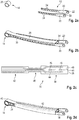
- FIG. 1 an example of a chassis component 10 is shown. This is a wishbone.
- other suspension components can be produced according to the invention, for example trailing arm.
- the transverse link 10 has a storage section 12, which is provided for connection to the vehicle body or an adjacent chassis component, a bearing receptacle 14, which receives a schematically indicated here bearing 16, which is provided for connection to a wheel or the vehicle body, and a strut 18th
- the strut 18 serves to mechanically connect the storage section 12 with the bearing receptacle 14.
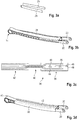
- FIGS. 2a to 2c Based on FIGS. 2a to 2c is the structure of an embodiment of the chassis component of FIG. 1 explained.
- the support portion 12 is here formed by two metal tabs 20 having a bearing lug 22 at one end and, starting at the opposite side, a plurality of apertures 24 having a comparatively small diameter and extending over a substantial portion of the length of the metal tabs 20 extend.
- the bearing receptacle 14 is symbolized here by a metal sleeve 26. It does not matter in the context of the present application how the bearing is concretely connected to the bearing receptacle 14. It is only important that the bearing, when the wishbone is made ready, is mechanically reliably absorbed in the bearing mount.
- the strut 18 has a strut body 28 and a jacket 30.
- the strut body 28 is an injection molded part made of a thermoplastic material.
- the bearing receptacle 14 of the strut body 28 is designed similar to a double-T-beam with a top flange and a lower flange, with additional transverse walls 32 are present.
- On the side of the storage section 12 of the strut body 28 is designed as a hollow box profile. Accordingly, an interior space 34 is enclosed by the walls of the strut body 28.
- the metal tabs 20 are inserted into the injection mold, that the material of the strut body 28 flows through the openings 24. This ensures that the metal tabs 20, when the material of the strut body is cured, are positively anchored to the strut body 28.
- the increased roughness may be generated by sand blasting or other surface treatment.
- Carbon fiber reinforced PPA is preferably used as material for the strut body 28.
- the jacket 30 is a fiber-plastic composite semifinished product (FKV semifinished product), that is, has a nonwoven 36 which carries high-strength fibers, in particular carbon fibers. These are arranged according to load path and represent a Fasergelege that means of Multiaxialgelegetechnik with warp thread offset can be produced. Such a hybrid fiber roving can be sewn to the nonwoven 36.
- FKV semifinished product fiber-plastic composite semifinished product
- the FKV semifinished product which later forms the jacket 30, is produced with a suitable contour in view of the fact that it will later enclose the strut body 28. It can be seen that it has a wide portion 38, a narrow central portion 40 and then a wider portion 42, wherein the width of the portion 38 is greater than the width of the portion 40.
- the portions 38, 42 are provided later, to enclose the strut body 28, while the narrow portion 40 is provided to enclose the bearing receptacle.
- FIG. 2c schematically indicated are some high-strength fibers 44, which are arranged on the web 36 on the path of the load path. It can be seen that the fibers 44 are distributed over the wider portions 38, 42 over a large area and from there extend continuously over the narrower section 40, where they are correspondingly closer to each other.
- the fibers 44 extend continuously from one of the wider portions 38, 42 over the narrower portion 40 to the other wider portion 42, 38. This is a difference to a scrim with a mat of carbon fibers, in which, in the region of the narrow portion 40, those fibers that are outside in the wider portions 38, 42 would be cut off. Also, the "fiber density”, ie the number of fibers transverse to the longitudinal direction of the FKV semifinished product, would be the same everywhere. In contrast, in the case 30 used here, the fiber density in the narrower section 40 is higher than in the wider sections 38, 42.
- the jacket 30 is provided with a plurality of sensors 46, of which only two are indicated here by way of example. They serve to continuously monitor the finished component during operation.
- the task of the sensors is to detect component deformations that exceed those that may occur during normal operation.
- the sensors are embodied here as so-called stick sensors, ie they consist of a metal wire (usually constantan), which is embroidered directly into the fleece 36. Schematically, two connections 48 for the sensors 46 are indicated.
- strain gauges have to be arranged at certain points and therefore only allow selective monitoring
- stick sensors can generally cover very large areas. In extreme cases, it is conceivable that the sensors 46 cover the entire web 36 in a planar manner.
- thermoplastic strut body 28 These values are advantageous for a fiber-plastic composite used for a thermoplastic strut body 28.
- the layer structure is additionally impregnated.
- the rolls are at a temperature of only about 60 ° C to 90 ° C.
- the jacket 30 is attached to the strut body 28 to see.
- the portion 42 of the shell 30 extends here on the top of the Strut body 28, while the section 38 is located on the bottom.
- the narrow portion 40 encloses the bearing receptacle 14 on the outside and thus extends from one side surface around the bearing receptacle 14 around on the other side surface.
- portion 38 is made wider than the portion 42 of the shell 30, the outer side edges can be "folded over” so that they rest on the narrower portion 42.
- FIGS. 3a to 3d a second embodiment is shown.
- the same reference numerals are used, and to that extent reference is made to the above explanations.
- the difference between the first and second embodiments is in particular in the material used for the strut body 28.
- the strut body 28 consists of a duroplastic, in particular a phenolic resin compound.
- the strut body 28 is made of several parts, namely from the actual strut body 28 and additionally two small lids 29 which are laterally recognized in extension of the metal tabs 20 and later glued or baked there with the strut body 28. This leads to a higher strength of the strut body 28th
- the mold temperature is in the order of 140 ° C to 160 ° C.
- both the strut body 28 and the jacket 30 are preheated.
- the strut body 28 is preheated to a temperature in the order of 160 ° C to 250 ° C. This can be done by means of hot air. Alternatively, infrared radiation can also be used.
- the FRP semifinished product ie, the subsequent jacket 30
- the FRP semifinished product will be preheated to a temperature below the melting temperature, e.g. at around 270 ° C. This can be done via contact heating. It is also conceivable to use this hot air.
- the FKV semi-finished product is melted to a temperature below the thermal degradation, e.g. at 350 ° C. This can be done by means of infrared radiation.
- the jacket 30 ie the FKV semi-finished product
- the jacket 30 is very well deformable, similar to a wet towel.
- the semi-finished FKV is suitably placed around the strut body 28 so that the sections 38, 42 extend over the side surfaces of the strut body 28 and the portion 40 wraps around the bearing receptacle 14. Then the jacket 30 is pressed firmly against the strut body 28, whereby the overlapping areas of the sections 38, 42 are pressed against each other.
- the liquid PPA of the FKV semi-finished product is pressed with the heated surface of the strut body 28 in one, so that a load-bearing adhesive bond between the shell 30 and the strut body 28 is formed.
- the overlapping portions of the jacket 30 stick together firmly.
- a 100-ton press with folding slide can be used for pressing the jacket 30 with the strut body 28 .
- the mold temperature during pressing is on the order of 250 ° C, with temperatures in the process room above 300 ° C.
- the temperature of the melt during injection is of the order of 80 ° C to 90 ° C.
- thermoset strut body 28 both components are first preheated to connect the jacket 30 with the strut body 28.
- the strut body 28 is preheated to a temperature of the order of 80 ° C to 160 ° C.
- the FRP semi-finished product (ie, the subsequent jacket 30) is first preheated to a temperature in the range of 80 ° C to 90 ° C and then, just before it is folded around the strut body 28, to a temperature in the order of 100 ° C. warmed up.
- the FRP semifinished product is laid around same in the same manner as in the thermoplastic strut body 28. Then the jacket 30 is pressed firmly against the strut body 28, whereby the overlapping areas of the sections 38, 42 are pressed against each other.
- the temperature of folding tool and press is in the range of 150 ° C to 170 ° C, so that the material of the strut body 28 hardens.
- the sensors 46 are preferably arranged on the side of the fleece 36, which faces the strut body 28. The sensors 46 are thus arranged protected inside the component.
Abstract
Die Erfindung betrifft ein Fahrwerkbauteil (10) für ein Kraftfahrzeug, mit einem Lagerungsabschnitt (12), der zur Anbindung an das Kraftfahrzeug vorgesehen ist, einer Lageraufnahme (14) für ein Lager, das zur Anbindung an einen Radträger vorgesehen ist, und einer Strebe (18), die den Lagerungsabschnitt (12) und die Lageraufnahme (14) miteinander verbindet, dadurch gekennzeichnet, dass die Strebe (18) ein Kunststoff-Verbundbauteil mit einem Strebenkörper und einem Mantel ist und der Lagerungsabschnitt (12) zwei Metalllaschen aufweist, die fest mit der Strebe (18) verbunden sind. Die Erfindung betrifft auch ein Verfahren zur Herstellung eines Fahrwerkbauteils für ein Kraftfahrzeug mittels der folgenden Schritte: - es werden zwei Metalllaschen bereitgestellt, die einen Lagerungsabschnitt (12) des Fahrwerkbauteils darstellen, mit dem dieses mit dem Kraftfahrzeug verbunden werden kann; - es wird ein Strebenkörper hergestellt und mit den Metalllaschen verbunden, wobei der Strebenkörper eine Lageraufnahme (14) aufweist; - es wird ein Mantel aus einem organoblech-ähnlichen Verband bereitgestellt, der um den Strebenkörper gewickelt wird, so dass er sich auch über die Lageraufnahme (14) erstreckt; - der Mantel wird verpresst.The invention relates to a chassis component (10) for a motor vehicle, having a bearing section (12) which is provided for connection to the motor vehicle, a bearing receptacle (14) for a bearing, which is provided for connection to a wheel carrier, and a strut (12). 18) interconnecting the support portion (12) and the bearing retainer (14), characterized in that the strut (18) is a plastic composite member having a strut body and a sheath and the support portion (12) has two metal tabs that are fixed are connected to the strut (18). The invention also relates to a method for producing a chassis component for a motor vehicle by means of the following steps: - There are two metal tabs provided, which constitute a storage portion (12) of the chassis component, with which it can be connected to the motor vehicle; - It is made a strut body and connected to the metal tabs, wherein the strut body has a bearing receptacle (14); a sheath of an organo-sheet-like dressing is provided, which is wound around the strut body so that it also extends over the bearing receptacle (14); - The coat is pressed.
Description
Die Erfindung betrifft ein Fahrwerkbauteil für ein Kraftfahrzeug, mit einem Lagerungsabschnitt, der zur Anbindung an das Kraftfahrzeug oder angrenzende Fahrwerkskomponenten vorgesehen ist, einer Lageraufnahme für ein Lager, das zur Anbindung an einen Radträger oder das Kraftfahrzeug vorgesehen ist, und einer Strebe, die den Lagerungsabschnitt und die Lageraufnahme miteinander verbindet. Die Erfindung betrifft ferner ein Verfahren zur Herstellung eines Fahrwerkbauteils.The invention relates to a chassis component for a motor vehicle, with a storage section, which is provided for connection to the motor vehicle or adjacent suspension components, a bearing receptacle for a bearing, which is provided for connection to a wheel or the motor vehicle, and a strut, the storage section and connects the bearing receiver. The invention further relates to a method for producing a chassis component.
Fahrwerkbauteile sind beispielsweise als Querlenker oder Längslenker bekannt. Sie dienen dazu, einen Radträger mit einem Aufhängungspunkt an der Fahrzeugkarosserie zu verbinden.Chassis components are known, for example as a wishbone or trailing arm. They serve to connect a wheel carrier with a suspension point on the vehicle body.
Aus verschiedenen Gründen ist es vorteilhaft, wenn die Fahrwerkbauteile möglichst leicht sind. Zum einen trägt ein geringes Gewicht zu einem geringen Fahrzeuggewicht bei. Dies ist sowohl für den Verbrauch des Fahrzeugs als auch die Fahrleistungen vorteilhaft. Zum anderen ist ein geringes Gewicht der Fahrwerkbauteile vorteilhaft für den Fahrkomfort, da die Fahrwerkbauteile zu den sogenannten ungefederten Massen gehören. Je geringer die ungefederten Massen, desto geringer sind die Auswirkungen von Fahrbahnunebenheiten auf den Fahrkomfort.For various reasons, it is advantageous if the chassis components are as light as possible. On the one hand, a low weight contributes to a low vehicle weight. This is advantageous for both the consumption of the vehicle and the performance. On the other hand, a low weight of the chassis components is advantageous for the ride comfort, since the chassis components belong to the so-called unsprung masses. The lower the unsprung masses, the lower the impact of road bumps on ride comfort.
Es ist bekannt, dass Fahrwerkbauteile als Schmiedeteile beispielsweise aus Aluminiumlegierungen hergestellt werden können. Es gibt auch schon Ansätze, Fahrwerkbauteile aus Kunststoffmaterialien herzustellen.It is known that chassis components can be manufactured as forgings, for example, from aluminum alloys. There are also approaches to produce suspension components made of plastic materials.
Die Aufgabe der Erfindung besteht darin, ein Fahrwerkbauteil zu schaffen, das sich durch ein extrem niedriges Gewicht bei hoher Belastbarkeit auszeichnet. Die Aufgabe der Erfindung besteht ferner darin, ein Verfahren zur Herstellung eines solchen Fahrwerkbauteils zu schaffen.The object of the invention is to provide a chassis component, which is characterized by an extremely low weight with high load capacity. The object of the invention is also to provide a method for producing such a chassis component.
Zur Lösung dieser Aufgabe ist erfindungsgemäß bei einem Fahrwerkbauteil der eingangs genannten Art vorgesehen, dass die Strebe ein Kunststoff-Verbundbauteil mit einem Strebenkörper und einem Mantel ist und der Lagerungsabschnitt zwei Metalllaschen aufweist, die fest mit der Strebe verbunden sind.To solve this problem is provided according to the invention in a chassis component of the type mentioned that the strut is a plastic composite component with a strut body and a jacket and the storage section has two metal tabs which are firmly connected to the strut.
Weiterhin ist zur Lösung dieser Aufgabe ein Verfahren vorgesehen, das die folgenden Schritte aufweist: Zunächst werden zwei Metalllaschen bereitgestellt, die einen Lagerungsabschnitt des Fahrwerkbauteils darstellen, mit dem dieses mit dem Kraftfahrzeug verbunden werden kann. Dann wird ein Strebenkörper hergestellt und mit den Metalllaschen verbunden, wobei der Strebenkörper eine Lageraufnahme aufweist. Außerdem wird ein Mantel aus einem organoblechähnlichen Verband bereitgestellt, der um den Strebenkörper gewickelt wird, sodass er sich auch über die Lageraufnahme erstreckt. Anschließend wird der Mantel verpresst.Furthermore, to solve this problem, a method is provided, which has the following steps: First, two metal tabs are provided, which represent a storage portion of the chassis component, with which this can be connected to the motor vehicle. Then, a strut body is manufactured and connected to the metal tabs, wherein the strut body has a bearing receptacle. In addition, a sheath of an organo-sheet-like dressing is provided, which is wound around the strut body, so that it extends over the bearing receptacle. Then the jacket is pressed.
Die Erfindung beruht auf dem Grundgedanken, durch geschickte Kombination der unterschiedlichen Materialien eine sehr hohe Festigkeit zu erzielen, sodass mit geringem Materialeinsatz gearbeitet werden kann, was zu einem entsprechend geringen Gewicht führt. Der Lagerungsabschnitt besteht aus zwei geometrisch einfachen Metalllaschen, die in ihrer Hauptbelastungsrichtung (Zug und Druck) sehr hohe Kräfte übertragen können. Der Strebenkörper dient zum einen dazu, die Metalllaschen zuverlässig aufzunehmen. Zum anderen dient der Strebenkörper als "Gerüst" für das Organoblech. Der Mantel bildet somit eine Art Hohlkastenprofil, das sich durch eine hohe Steifigkeit und Belastbarkeit auszeichnet.The invention is based on the basic idea to achieve a very high strength by skillful combination of different materials, so that you can work with low material usage, resulting in a correspondingly low weight. The storage section consists of two geometrically simple metal tabs that can transmit very high forces in their main load direction (train and pressure). The strut body serves on the one hand to reliably receive the metal tabs. On the other hand, the strut body serves as a "scaffold" for the organic sheet. The jacket thus forms a kind of hollow box profile, which is characterized by a high rigidity and resilience.
Vorzugsweise sind die Metalllaschen formschlüssig mit der Strebe verbunden. Hierdurch ergibt sich eine besonders hohe Festigkeit der Verbindung zwischen den Metalllaschen und dem Strebenkörper.Preferably, the metal tabs are positively connected to the strut. This results in a particularly high strength of the connection between the metal tabs and the strut body.
Die Metalllaschen können beispielsweise Öffnungen aufweisen, durch die hindurch sich Material des Strebenkörpers erstreckt. Dadurch ergibt sich eine Vielzahl von Lasteinleitungspunkten, wodurch Lastspitzen vermieden werden.The metal tabs may, for example, have openings through which material of the strut body extends. This results in a variety of load application points, which load peaks are avoided.
Es kann auch vorgesehen sein, dass das Material des Strebenkörpers an den Metalllaschen haftet. Hierdurch ergibt sich eine Art Klebeverbindung, sodass eine besonders große Kraftübertragungsfläche zur Verfügung steht. Abgesehen von der geeigneten Auswahl des Materials für den Strebenkörper wird die Belastbarkeit dieser Klebeverbindung maßgeblich beeinflusst von der Oberflächenrauigkeit der Metalllaschen. Es hat sich als sehr vorteilhaft herausgestellt, dass die aus einer üblichen Oberflächenbehandlung resultierende Rauigkeit, beispielsweise nach einer Zink-Nickel-Behandlung, bereits ausreichend sein kann, dass das Material des Strebenkörpers sich fest mit den Metalllaschen verbindet. Falls nötig, kann auch ein Haftvermittler verwendet werden.It can also be provided that the material of the strut body adheres to the metal straps. This results in a kind of adhesive bond, so that a particularly large power transmission surface is available. Apart from the suitable selection of the material for the strut body, the resilience of this adhesive bond is significantly influenced by the surface roughness of the metal tabs. It has proved to be very advantageous that the roughness resulting from a conventional surface treatment, for example after a zinc-nickel treatment, may already be sufficient for the material of the strut body to bond firmly to the metal tabs. If necessary, an adhesion promoter can also be used.
Als Material für die Metalllaschen kann hochfester Stahl verwendet werden. Es ist auch denkbar, die Metalllaschen aus einer Aluminiumlegierung herzustellen.High-strength steel can be used as material for the metal tabs. It is also conceivable to produce the metal tabs from an aluminum alloy.
Der Strebenkörper ist vorzugsweise ein Spritzgussteil, sodass eine hohe Variabilität hinsichtlich seiner Geometrie gegeben ist.The strut body is preferably an injection molded part, so that a high variability is given in terms of its geometry.
Gemäß einer Ausgestaltung kann der Strebenkörper aus einem Hochtemperatur-Polyamid bestehen. Dieses Material vereinbart eine gute Verarbeitbarkeit mit hoher Festigkeit. Dies gilt insbesondere, wenn der Strebenkörper aus kohlefaserverstärktem PPA besteht.According to one embodiment, the strut body may consist of a high-temperature polyamide. This material agrees good workability with high strength. This is especially true when the strut body is made of carbon fiber reinforced PPA.
Gemäß einer alternativen Ausgestaltung besteht der Strebenkörper aus einem Phenolharzcompound. Dieses Material stellt höhere Anforderungen bei der Verarbeitung, zeichnet sich aber durch eine sehr hohe Festigkeit auch bei hohen Temperaturen aus.According to an alternative embodiment, the strut body consists of a phenolic resin compound. This material places greater demands on processing, but is characterized by a very high strength even at high temperatures.
Der Mantel weist vorzugsweise hochfeste Endlos-Fasern auf, beispielsweise Glas- oder Aramidfasern und insbesondere Kohlenstofffasern. Hierdurch ergibt sich eine sehr hohe Festigkeit des Mantels.The sheath preferably has high-strength endless fibers, for example glass or aramid fibers and in particular carbon fibers. This results in a very high strength of the shell.
Der Mantel weist vorzugsweise ein Vlies auf, auf dem die hochfesten Fasern entlang von Lastpfaden drapiert sind. Die hochfesten Fasern werden also auf dem Vlies in einer an die auftretenden Belastungen angepassten Weise angeordnet. Dies stellt einen wichtigen Unterschied dar zu sogenannten Prepregs, bei denen die hochfesten Fasern beispielsweise in der Form eines Gewebes gleichmäßig verteilt sind und aus denen dann die gewünschten Zuschnitte hergestellt werden. Dabei werden notwendigerweise einzelne Fasern unterbrochen, wenn der Zuschnitt eine etwas komplexere Form hat, beispielsweise Einschnürungen. Werden die hochfesten Fasern dagegen in geeigneter Weise auf dem Vlies drapiert, verlaufen sie ohne Unterbrechung über den gesamten Mantel, was zu einer deutlich gesteigerten Festigkeit führt.The sheath preferably comprises a nonwoven on which the high strength fibers are draped along load paths. The high-strength fibers are thus arranged on the fleece in a manner adapted to the loads occurring. This is an important difference to so-called prepregs, in which the high-strength fibers are uniformly distributed, for example in the form of a fabric and from which then the desired blanks are made. In this case, individual fibers are necessarily interrupted when the blank has a slightly more complex shape, such as constrictions. In contrast, the high-strength fibers in a suitable manner on the fleece Draped, they run uninterrupted over the entire coat, which leads to a significantly increased strength.
Der Mantel ist in einer Ausführungsform vorzugsweise mit einem Epoxidharz imprägniert, sodass er mit geringem Aufwand weiterverarbeitet und ausgehärtet werden kann.The jacket is preferably impregnated in one embodiment with an epoxy resin, so that it can be further processed and cured with little effort.
Vorzugsweise erstreckt sich der Mantel entlang einer Seite des Strebenkörpers, um die Lageraufnahme und zurück auf der entgegengesetzten Seite des Strebenkörpers. Dies gewährleistet, dass Zugbelastungen, die auf die Lageraufnahme einwirken, vom Mantel zuverlässig aufgefangen werden.Preferably, the jacket extends along one side of the strut body, around the bearing receiver and back on the opposite side of the strut body. This ensures that tensile loads, which act on the bearing seat, are reliably absorbed by the jacket.
Die sich entlang der Seiten des Strebenkörpers erstreckenden Teile des Mantels sind dabei vorzugsweise breiter als der sich um die Lageraufnahme erstreckende Teil des Mantels, sodass im Bereich der Seiten des Strebenkörpers genügend Material zur Verfügung steht, damit der Mantel einen geschlossenen Querschnitt bilden kann.The parts of the jacket which extend along the sides of the strut body are preferably wider than the part of the jacket extending around the bearing receiver, so that sufficient material is available in the region of the sides of the strut body so that the jacket can form a closed cross section.
Hierfür ist es insbesondere vorteilhaft, dass einer der beiden sich entlang des Strebenkörpers erstreckenden Teile des Mantels breiter ist als der andere Teil und den schmäleren Teil außen umgreift. Die Seitenränder des breiteren Teils des Mantels wirken ähnlich wie Flügel, die mit dem schmäleren Teil verklebt werden können, sodass eine großflächige Verbindung entlang nahezu der gesamten Länge des Fahrwerkbauteils möglich ist.For this purpose, it is particularly advantageous that one of the two along the strut body extending parts of the shell is wider than the other part and the narrower part engages around the outside. The side edges of the wider portion of the shell act similar to wings that can be glued to the narrower part, so that a large area connection along almost the entire length of the chassis component is possible.
Gemäß einer bevorzugten Ausführungsform der Erfindung ist in den Mantel ein Sensor integriert, der Strukturschäden des Fahrwerkbauteils erkennen kann. Der Sensor dient insbesondere dazu, Verformungen des Fahrwerkbauteils zu erfassen, die auf unsachgemäße Belastungen zurückgehen und langfristig zum Versagen führen könnten.According to a preferred embodiment of the invention, a sensor is integrated into the jacket, which can detect structural damage of the chassis component. The sensor is used in particular to detect deformations of the chassis component, which go back to improper loads and in the long run could lead to failure.
Der Sensor kann insbesondere ein Sticksensor sein, also gebildet durch mehrere dünne Metallfäden, die in das Vlies des Mantels eingestickt sind. Verformungen des Fahrwerkbauteils, die über einen bestimmten Betrag hinausgehen, führen zu einer Dehnung der Metallfasern, woraus eine Änderung des Widerstands der Metallfasern resultiert. Eine solche Änderung des Widerstands kann mit einer sehr einfachen Schaltung, beispielsweise einer Brückenschaltung, detektiert werden. Somit kann frühzeitig signalisiert werden, dass das Fahrwerkbauteil in einer Werkstatt untersucht werden sollte. Wenn stärkere strukturelle Schäden erfasst werden, kann der Fahrer auch aufgefordert werden, das Fahrzeug unverzüglich abzustellen. Denkbar ist auch, dass die Inbetriebnahme des Fahrzeugs, wenn ein stärkerer struktureller Schaden erfasst wurde, präventiv verhindert wird.The sensor may in particular be a stick sensor, that is to say formed by a plurality of thin metal threads which are embroidered in the fleece of the sheath. Deformations of the chassis component that exceed a certain amount lead to an expansion of the metal fibers, resulting in a change in the resistance of the metal fibers. Such a change in the resistance can be detected with a very simple circuit, for example a bridge circuit. Thus it can be signaled early that the chassis component should be examined in a workshop. If more severe structural damage is detected, the driver may also be requested to stop the vehicle immediately. It is also conceivable that the commissioning of the vehicle, if more structural damage was detected, is preventively prevented.
Der Strebenkörper kann aus einem thermoplastischen Material spritzgegossen werden, also mit einem Verfahren, das sehr gut beherrscht wird und kostengünstig durchgeführt werden kann.The strut body can be injection molded from a thermoplastic material, so with a process that is very well controlled and can be carried out inexpensively.
Es ist auch möglich, dass der Strebenkörper aus einem duroplastischen Material besteht, das unterhalb der Quervernetzungstemperatur spritzgegossen wird. Hierdurch ist das Material besonders gut verarbeitbar. Zum Aushärten wird der Strebenkörper nachträglich ausreichend erwärmt.It is also possible that the strut body consists of a thermoset material that is injection molded below the cross-linking temperature. As a result, the material is particularly easy to process. To harden the strut body is subsequently sufficiently heated.
Vorzugsweise wird der Mantel mit hochfesten Fasern versehen, die mittels Multiaxialgelegetechnik angeordnet werden. Dies ermöglicht es, die hochfesten Fasern in der gewünschten Weise optimal anzuordnen, sodass eine maximale Belastbarkeit erzielt wird.Preferably, the sheath is provided with high-strength fibers which are arranged by means of Multiaxialgelegetechnik. This makes it possible to optimally arrange the high-strength fibers in the desired manner, so that a maximum load capacity is achieved.
Der Mantel kann, bevor er auf den Strebenkörper aufgebracht wird, erwärmt werden. Hierdurch ist der Mantel optimal verformbar, sodass er um den Strebenkörper herumgelegt werden kann und sich optimal an diesen anschmiegt.The jacket can be heated before it is applied to the strut body. As a result, the jacket is optimally deformable, so that it can be wrapped around the strut body and optimally clings to them.
Vorzugsweise ist vorgesehen, dass der Strebenkörper, bevor der Mantel aufgebracht wird, erwärmt wird. Dies unterstützt das flächige Verkleben des Mantels mit dem Strebenkörper.It is preferably provided that the strut body, before the jacket is applied, is heated. This supports the surface bonding of the shell with the strut body.
Nachdem der Mantel um den Strebenkörper herumgelegt wurde, wird er mit einer Temperatur zwischen 90°C und 300°C auf den Strebenkörper gepresst. Die Temperatur hängt ab von den jeweils verwendeten Materialien. Durch das Verpressen wird gewährleistet, dass der Mantel mit dem Strebenkörper zu einer unlösbaren Einheit "verbackt".After the jacket has been wrapped around the strut body, it is pressed at a temperature between 90 ° C and 300 ° C on the strut body. The temperature depends on the materials used. By pressing it is ensured that the jacket with the strut body "bakes" to an insoluble unit.
Die Erfindung wird nachfolgend anhand zweier Ausführungsformen beschrieben, die in den beigefügten Zeichnungen dargestellt sind. In diesen zeigen:
-
Figur 1 in einer perspektivischen Ansicht ein erfindungsgemäßes Fahrwerkbauteil; - die
Figuren 2a bis 2d die verschiedenen Komponenten eines Fahrwerkbauteils gemäß einer ersten Ausführungsform; - die
Figuren 3a bis 3d die verschiedenen Komponenten eines Fahrwerkbauteils gemäß einer zweiten Ausführungsform; und -
Figur 4 schematisch die verschiedenen Schritte bei der Herstellung eines erfindungsgemäßen Fahrwerkbauteils.
-
FIG. 1 in a perspective view of an inventive chassis component; - the
FIGS. 2a to 2d the various components of a chassis component according to a first embodiment; - the
FIGS. 3a to 3d the various components of a chassis component according to a second embodiment; and -
FIG. 4 schematically the various steps in the production of a chassis component according to the invention.
In
Der Querlenker 10 weist einen Lagerungsabschnitt 12 auf, der zur Anbindung an der Fahrzeugkarosserie oder eine angrenzende Fahrwerkskomponente vorgesehen ist, eine Lageraufnahme 14, die ein hier schematisch angedeutetes Lager 16 aufnimmt, das zur Anbindung an einen Radträger oder die Fahrzeugkarosserie vorgesehen ist, und eine Strebe 18.The
Die Strebe 18 dient dazu, den Lagerungsabschnitt 12 mit der Lageraufnahme 14 mechanisch zu verbinden.The
Anhand der
Der Lagerungsabschnitt 12 ist hier gebildet durch zwei Metalllaschen 20, die an einem Ende ein Lagerauge 22 aufweisen und, beginnend an der entgegengesetzten Seite, eine Vielzahl von Öffnungen 24, die einen vergleichsweise kleinen Durchmesser haben und sich über einen wesentlichen Teil der Länge der Metalllaschen 20 erstrecken.The
Die Lageraufnahme 14 ist hier durch eine Metallhülse 26 symbolisiert. Es kommt im Rahmen der vorliegenden Anmeldung nicht darauf an, wie das Lager konkret mit der Lageraufnahme 14 verbunden wird. Wichtig ist lediglich, dass das Lager, wenn der Querlenker fertig hergestellt ist, mechanisch zuverlässig in der Lageraufnahme aufgenommen ist.The bearing
Die Strebe 18 weist einen Strebenkörper 28 sowie einen Mantel 30 auf.The
Der Strebenkörper 28 ist ein Spritzgussteil aus einem thermoplastischen Kunststoff.The
Auf der Seite der Lageraufnahme 14 ist der Strebenkörper 28 ähnlich wie ein Doppel-T-Träger mit einem Obergurt und einem Untergurt ausgeführt, wobei zusätzliche Querwände 32 vorhanden sind. Auf der Seite des Lagerungsabschnittes 12 ist der Strebenkörper 28 als Hohlkastenprofil ausgeführt. Dementsprechend ist von den Wänden des Strebenkörpers 28 ein Innenraum 34 umschlossen.On the side of the bearing
Bei der Herstellung des Strebenkörpers 28 werden die Metalllaschen 20 so in die Spritzgussform eingelegt, dass das Material des Strebenkörpers 28 durch die Öffnungen 24 hindurchfließt. Dies gewährleistet, dass die Metalllaschen 20, wenn das Material des Strebenkörpers ausgehärtet ist, formschlüssig am Strebenkörper 28 verankert sind.In the production of the
Alternativ oder zusätzlich kann zur Verbindung der Metalllaschen 20 mit dem Strebenkörper 28 ausgenutzt werden, dass das Material des Strebenkörpers 28 an den Metalllaschen 20 anhaftet, also an diesem klebt. Hierfür kann in einer vorteilhaften Weise ausgenutzt werden, dass übliche Oberflächenbehandlungen, beispielsweise eine Zink-Nickel-Behandlung, zu einer erhöhten Rauigkeit der Oberfläche der Metalllaschen 20 führt.Alternatively or additionally, can be exploited to connect the
Alternativ kann die erhöhte Rauigkeit durch Sandstrahlen oder eine andere Oberflächenbearbeitung erzeugt werden.Alternatively, the increased roughness may be generated by sand blasting or other surface treatment.
Als Material für den Strebenkörper 28 wird vorzugsweise kohlefaserverstärktes PPA verwendet.Carbon fiber reinforced PPA is preferably used as material for the
In
Der Mantel 30 ist ein Faser-Kunststoff-Verbund-Halbzeug (FKV-Halbzeug), weist also ein Vlies 36 auf, das hochfeste Fasern trägt, insbesondere Kohlenstofffasern. Diese sind lastpfadgerecht angeordnet und stellen ein Fasergelege dar, das mittels Multiaxialgelegetechnik mit Kettfadenversatz hergestellt werden kann. Ein solches Hybridfaserroving kann mit dem Vlies 36 vernäht werden.The
Das FKV-Halbzeug, das später den Mantel 30 bildet, ist im Hinblick darauf, dass er später den Strebenkörper 28 umschließen soll, mit geeigneter Kontur hergestellt. Es ist zu sehen, dass es einen breiten Abschnitt 38, einen schmalen Mittelabschnitt 40 und dann wieder einen breiteren Abschnitt 42 aufweist, wobei die Breite des Abschnittes 38 größer ist als die Breite des Abschnittes 40. Die Abschnitte 38, 42 sind später dafür vorgesehen, den Strebenkörper 28 zu umschließen, während der schmale Abschnitt 40 dafür vorgesehen ist, die Lageraufnahme zu umschließen.The FKV semifinished product, which later forms the
In
Wichtig ist, dass die Fasern 44 durchgehend von einem der breiteren Abschnitte 38, 42 über den schmäleren Abschnitt 40 auf den anderen breiteren Abschnitt 42, 38 verlaufen. Dies stellt einen Unterschied dar zu einem Gelege mit einer Matte aus Kohlenstofffasern, bei der im Bereich des schmalen Abschnittes 40 diejenigen Fasern, die in den breiteren Abschnitten 38, 42 außen liegen, abgeschnitten wären. Auch wäre die "Faserdichte", also die Anzahl der Fasern quer zur Längsrichtung des FKV-Halbzeugs, überall gleich. Dagegen ist beim hier verwendeten Mantel 30 die Faserdichte im schmäleren Abschnitt 40 höher als in den breiteren Abschnitten 38, 42.Importantly, the
Der Mantel 30 ist mit mehreren Sensoren 46 versehen, von denen hier beispielhaft lediglich zwei angedeutet sind. Sie dienen dazu, das fertige Bauteil im Betrieb kontinuierlich zu überwachen.The
Bei Fahrwerkbauteilen, die aus Metalllegierungen bestehen, führt eine Überbelastung, aufgrund der Duktilität des Materials, zunächst zu einer plastischen Verformung oder lokalen Schädigung. Dies ist meist unkritisch; bevor sich die Schädigung zu einem strukturellen Problem ausweitet, wird die Schädigung bei einer Inspektion erkannt. Bei Kunststoffbauteilen, insbesondere bei faserverstärkten Bauteilen, kann eine Überbelastung jedoch eine solche lokale Schädigung hervorrufen, dass das Bauteil irgendwann plötzlich versagt, ohne dass das Bauteil vorher bei einer Inspektion als auffällig erkannt wurde. Dies kann verhindert werden, indem geeignete Sensoren in das Bauteil integriert werden.In the case of chassis components made of metal alloys, overloading due to the ductility of the material initially leads to plastic deformation or local damage. This is usually not critical; before the damage becomes a structural problem, the damage is detected during an inspection. For plastic components, in particular However, in the case of fiber-reinforced components, an overload can cause such local damage that the component suddenly fails at some point without the component being previously detected as being conspicuous during an inspection. This can be prevented by integrating suitable sensors into the component.
Die Aufgabe der Sensoren besteht darin, Verformungen der Bauteile zu erfassen, die über diejenigen hinausgehen, die im normalen Betrieb auftreten dürfen.The task of the sensors is to detect component deformations that exceed those that may occur during normal operation.
Die Sensoren sind hier als sogenannte Sticksensoren ausgeführt, bestehen also aus einem Metalldraht (üblicherweise Konstantan), der direkt in das Vlies 36 eingestickt ist. Schematisch sind auch zwei Anschlüsse 48 für die Sensoren 46 angedeutet.The sensors are embodied here as so-called stick sensors, ie they consist of a metal wire (usually constantan), which is embroidered directly into the
Vom Grundprinzip arbeiten solchen Sensoren ähnlich wie Dehnmessstreifen. Allerdings sind sie vollständig in den Mantel 30 integriert. Es gibt auch keine Einschränkungen bei der Anordnung. Während Dehnmessstreifen an bestimmten Stellen angeordnet werden müssen und von daher lediglich eine punktuelle Überwachung ermöglichen, können Sticksensoren grundsätzlich sehr große Flächen abdecken. Im Extremfall ist denkbar, dass die Sensoren 46 das gesamte Vlies 36 flächig abdecken.The basic principle of such sensors is similar to strain gauges. However, they are fully integrated into the
Bei der Herstellung des FKV-Halbzeugs erfolgt ein Vorkonsolidieren und Konfektionieren des FKV-Preforms durch heißes Walzen. Dabei werden drei Lagen zusammengewalzt. Dies kann mit einer Vorschubgeschwindigkeit in der Größenordnung von 6 bis 7 m/min erfolgen, wobei sich die Walzen auf einer Temperatur von etwa 290 °C befinden. Der Walzdruck liegt im Bereich von 1 bis 10 MPa, so dass sich ein organoblech-ähnlicher Verband ergibtIn the production of the semi-finished FKV pre-consolidating and finishing of the FKV preform by hot rolling takes place. Here, three layers are rolled together. This can be done at a feed rate of the order of 6 to 7 m / min with the rolls at a temperature of about 290 ° C. The rolling pressure is in the range of 1 to 10 MPa, resulting in an organo-sheet-like dressing
Diese Werte sind vorteilhaft für einen Faser-Kunststoff-Verbund, der für einen thermoplastischen Strebenkörper 28 verwendet wird.These values are advantageous for a fiber-plastic composite used for a
Ist der Faser-Kunststoff-Verbund für einen duroplastischen Strebenkörper vorgesehen, wird zusätzlich der Lagenaufbau imprägniert. Außerdem befinden sich die Walzen auf einer Temperatur von lediglich etwa 60°C bis 90 °C.If the fiber-plastic composite is intended for a thermoset strut body, the layer structure is additionally impregnated. In addition, the rolls are at a temperature of only about 60 ° C to 90 ° C.
In
Da der Abschnitt 38 breiter ausgeführt ist als der Abschnitt 42 des Mantels 30, können die außen liegenden Seitenränder "umgefaltet" werden, sodass sie auf dem schmäleren Abschnitt 42 aufliegen.Since the
In den
Der Unterschied zwischen der ersten und der zweiten Ausführungsform besteht insbesondere im Material, das für den Strebenkörper 28 verwendet wird. Der Strebenkörper 28 besteht bei der zweiten Ausführungsform nämlich aus einem Duroplast, insbesondere einem Phenolharzcompound.The difference between the first and second embodiments is in particular in the material used for the
Es kann außerdem vorgesehen sein, dass der Strebenkörper 28 mehrteilig ausgeführt ist, nämlich aus dem eigentlichen Strebenkörper 28 und zusätzlich zwei kleinen Deckeln 29, die in Verlängerung der Metalllaschen 20 seitlich angesetzt und dort mit dem Strebenkörper 28 später verklebt oder verbacken werden. Dies führt zu einer höheren Festigkeit des Strebenkörpers 28.It may also be provided that the
Anhand von
Der Strebenkörper 28 wird, wenn er aus thermoplastischem Material besteht, mit einer Temperatur der Schmelze in der Größenordnung von 300°C bis 350°C gespritzt. Die Werkzeugtemperatur liegt dabei in der Größenordnung von 140°C bis 160°C.The
Um den Mantel 30 mit dem Strebenkörper 28 zu verbinden, werden zunächst sowohl der Strebenkörper 28 als auch der Mantel 30 vorgewärmt.In order to connect the
Der Strebenkörper 28 wird auf eine Temperatur in der Größenordnung von 160°C bis 250°C vorgewärmt. Dies kann mittels Heißluft erfolgen. Alternativ kann auch Infrarotstrahlung verwendet werden.The
Das FKV-Halbzeug (also der spätere Mantel 30) wird auf eine Temperatur unterhalb der Schmelztemperatur vorgewärmt werden, z.B. auf rund 270°C. Dies kann über eine Kontaktheizung erfolgen. Denkbar ist auch, hierfür Heißluft zu verwenden.The FRP semifinished product (ie, the subsequent jacket 30) will be preheated to a temperature below the melting temperature, e.g. at around 270 ° C. This can be done via contact heating. It is also conceivable to use this hot air.
Anschließend wird das FKV-Halbzeug auf eine Temperatur unterhalb der thermischen Degradation aufgeschmolzen, z.B. auf 350°C. Dies kann mittels Infrarotstrahlung erfolgen.Subsequently, the FKV semi-finished product is melted to a temperature below the thermal degradation, e.g. at 350 ° C. This can be done by means of infrared radiation.
Bei dieser Temperatur ist der Mantel 30 (also das FKV-Halbzeug) sehr gut verformbar, ähnlich einem nassen Handtuch.At this temperature, the jacket 30 (ie the FKV semi-finished product) is very well deformable, similar to a wet towel.
Nach dem Aufschmelzen wird das FKV-Halbzeug geeignet so um den Strebenkörper 28 gelegt, dass sich die Abschnitte 38, 42 über die Seitenflächen des Strebenkörpers 28 erstrecken und der Abschnitt 40 die Lageraufnahme 14 umschlingt. Dann wird der Mantel 30 fest gegen den Strebenkörper 28 gepresst, wobei auch die einander überlappenden Bereiche der Abschnitte 38, 42 gegeneinander gedrückt werden.After melting, the semi-finished FKV is suitably placed around the
Dabei wird das flüssige PPA des FKV-Halbzeugs mit der erwärmten Oberfläche des Strebenkörpers 28 in einem verpresst, sodass eine lasttragende Haftverbindung zwischen dem Mantel 30 und dem Strebenkörper 28 entsteht. Außerdem verkleben die einander überlappenden Abschnitte des Mantels 30 fest miteinander.In this case, the liquid PPA of the FKV semi-finished product is pressed with the heated surface of the
Zum Verpressen des Mantels 30 mit dem Strebenkörper 28 kann eine 100-Tonnen-Presse mit Faltschieber verwendet werden. Die Werkzeugtemperatur beim Verpressen liegt in der Größenordnung von 250°C, wobei im Prozessraum Temperaturen oberhalb von 300°C vorliegen.For pressing the
Wenn der Strebenkörper 28 aus duroplastischem Material besteht, liegt die Temperatur der Schmelze beim Spritzen in der Größenordnung von 80°C bis 90°C.When the
Auch beim duroplastischen Strebenkörper 28 werden zum Verbinden des Mantels 30 mit dem Strebenkörper 28 beide Bauteile zunächst vorgewärmt.Also in the
Der Strebenkörper 28 wird auf eine Temperatur in der Größenordnung von 80°C bis 160°C vorgewärmt.The
Das FKV-Halbzeug (also der spätere Mantel 30) wird zunächst auf eine Temperatur im Bereich von 80°C bis 90°C vorgewärmt und anschließend, kurz bevor es um den Strebenkörper 28 gefaltet wird, auf eine Temperatur in der Größenordnung von 100°C aufgewärmt.The FRP semi-finished product (ie, the subsequent jacket 30) is first preheated to a temperature in the range of 80 ° C to 90 ° C and then, just before it is folded around the
Nach dem Aufwärmen wird das FKV-Halbzeug in der gleichen Weise wie beim thermoplastischen Strebenkörper 28 um diesen gelegt. Dann wird der Mantel 30 fest gegen den Strebenkörper 28 gepresst, wobei auch die einander überlappenden Bereiche der Abschnitte 38, 42 gegeneinander gedrückt werden.After warming up, the FRP semifinished product is laid around same in the same manner as in the
Die Temperatur von Faltwerkzeug und Presse liegt dabei im Bereich von 150°C bis 170°C, damit das Material des Strebenkörpers 28 aushärtet.The temperature of folding tool and press is in the range of 150 ° C to 170 ° C, so that the material of the
Die Sensoren 46 sind vorzugsweise auf der Seite des Vlieses 36 angeordnet, die dem Strebenkörper 28 zugewandt ist. Die Sensoren 46 sind also geschützt im Inneren des Bauteils angeordnet.The
Claims (24)
Applications Claiming Priority (1)
| Application Number | Priority Date | Filing Date | Title |
|---|---|---|---|
| DE102017107463.5A DE102017107463B3 (en) | 2017-04-06 | 2017-04-06 | Chassis component and method for its production |
Publications (2)
| Publication Number | Publication Date |
|---|---|
| EP3395591A1 true EP3395591A1 (en) | 2018-10-31 |
| EP3395591B1 EP3395591B1 (en) | 2021-09-01 |
Family
ID=61911479
Family Applications (1)
| Application Number | Title | Priority Date | Filing Date |
|---|---|---|---|
| EP18166063.0A Active EP3395591B1 (en) | 2017-04-06 | 2018-04-06 | Chassis part and method for its production |
Country Status (2)
| Country | Link |
|---|---|
| EP (1) | EP3395591B1 (en) |
| DE (1) | DE102017107463B3 (en) |
Cited By (2)
| Publication number | Priority date | Publication date | Assignee | Title |
|---|---|---|---|---|
| CN110937119A (en) * | 2019-12-24 | 2020-03-31 | 肇庆市海特复合材料技术研究院 | Integrated full-composite material connecting rod structure |
| US11649850B2 (en) * | 2019-06-23 | 2023-05-16 | Albany Engineered Composites, Inc. | Rod end made of thermoplastic fiber-reinforced plastic |
Families Citing this family (2)
| Publication number | Priority date | Publication date | Assignee | Title |
|---|---|---|---|---|
| DE102019102493A1 (en) | 2019-01-31 | 2020-08-06 | Benteler Automobiltechnik Gmbh | Motor vehicle driver |
| DE102020127863A1 (en) | 2020-10-22 | 2022-04-28 | THK RHYTHM AUTOMOTIVE GmbH | Torsion beam for a chassis of a motor vehicle |
Citations (12)
| Publication number | Priority date | Publication date | Assignee | Title |
|---|---|---|---|---|
| US20050044984A1 (en) * | 2003-08-27 | 2005-03-03 | Jones Brian H. | Reinforced tension and compression reacting strut and method of making same |
| FR2862559A1 (en) * | 2003-11-24 | 2005-05-27 | Cf Gomma Spa | Motor vehicle axle suspension arm manufacturing procedure has articulated joints overmolded in polymer onto ends of rigid bar |
| JP3705384B2 (en) * | 1996-10-05 | 2005-10-12 | 東邦テナックス株式会社 | Suspension arm and manufacturing method thereof |
| DE102008054669A1 (en) * | 2008-12-15 | 2010-06-17 | Zf Friedrichshafen Ag | Axle for a motor vehicle |
| DE102011010367A1 (en) * | 2011-02-04 | 2012-08-09 | Daimler Ag | Suspension part i.e. control arm, for motor vehicle i.e. passenger car, has amplification structure made of plastic to amplify base body, where base body is made of fiber reinforced plastic using fiber depositor |
| WO2013066727A1 (en) * | 2011-11-03 | 2013-05-10 | The Boeing Company | Composite columnar structure having co-bonded reinforcement and fabrication method |
| DE102013007375A1 (en) * | 2013-04-27 | 2014-03-20 | Daimler Ag | Landing gear part e.g. wishbone, for motor vehicle, has two shell-shaped fiber-reinforced plastic parts provided in base body, and reinforced cavity formed between fiber-reinforced plastic parts by plastic structure |
| EP2722533A1 (en) * | 2012-10-18 | 2014-04-23 | Epsilon Composite | Method for gluing two parts which are subject to tensile forces, glued pieces obtained |
| DE102012111097A1 (en) * | 2012-11-19 | 2014-05-22 | Dbw Holding Gmbh | Composite, component thereof and method of making the same |
| DE102014218601A1 (en) * | 2014-09-16 | 2016-03-17 | Bayerische Motoren Werke Aktiengesellschaft | Radführender handlebar of a vehicle chassis |
| EP3053761A1 (en) * | 2013-10-02 | 2016-08-10 | Nhk Spring Co., Ltd. | Suspension arm member |
| EP3112193A1 (en) * | 2015-07-02 | 2017-01-04 | Edai Technical Unit, A.I.E. | Method for obtaining a suspension arm for automotive vehicles and suspension arm |
Family Cites Families (7)
| Publication number | Priority date | Publication date | Assignee | Title |
|---|---|---|---|---|
| US367942A (en) * | 1887-08-09 | Benjamin p | ||
| US5921054A (en) | 1996-06-21 | 1999-07-13 | University Of Central Florida | Metal and wood composite framing members for residential and light commercial construction |
| US6421979B1 (en) | 1999-09-16 | 2002-07-23 | Basf Aktiengesellschaft | Composite constructional element |
| US8904904B2 (en) * | 2011-11-03 | 2014-12-09 | The Boeing Company | Tubular composite strut having internal stiffening |
| JP5561445B2 (en) | 2012-06-08 | 2014-07-30 | 新日鐵住金株式会社 | CONNECTION STRUCTURE, CONNECTION MEMBER HAVING CONNECTION STRUCTURE, AND METHOD FOR PRODUCING CONNECTION MEMBER HAVING CONNECTION STRUCTURE |
| DE102012218686A1 (en) | 2012-10-15 | 2014-04-17 | Zf Friedrichshafen Ag | Component for a chassis of a vehicle |
| DE102015218026A1 (en) | 2015-09-18 | 2017-03-23 | Zf Friedrichshafen Ag | Torque rod |
-
2017
- 2017-04-06 DE DE102017107463.5A patent/DE102017107463B3/en active Active
-
2018
- 2018-04-06 EP EP18166063.0A patent/EP3395591B1/en active Active
Patent Citations (12)
| Publication number | Priority date | Publication date | Assignee | Title |
|---|---|---|---|---|
| JP3705384B2 (en) * | 1996-10-05 | 2005-10-12 | 東邦テナックス株式会社 | Suspension arm and manufacturing method thereof |
| US20050044984A1 (en) * | 2003-08-27 | 2005-03-03 | Jones Brian H. | Reinforced tension and compression reacting strut and method of making same |
| FR2862559A1 (en) * | 2003-11-24 | 2005-05-27 | Cf Gomma Spa | Motor vehicle axle suspension arm manufacturing procedure has articulated joints overmolded in polymer onto ends of rigid bar |
| DE102008054669A1 (en) * | 2008-12-15 | 2010-06-17 | Zf Friedrichshafen Ag | Axle for a motor vehicle |
| DE102011010367A1 (en) * | 2011-02-04 | 2012-08-09 | Daimler Ag | Suspension part i.e. control arm, for motor vehicle i.e. passenger car, has amplification structure made of plastic to amplify base body, where base body is made of fiber reinforced plastic using fiber depositor |
| WO2013066727A1 (en) * | 2011-11-03 | 2013-05-10 | The Boeing Company | Composite columnar structure having co-bonded reinforcement and fabrication method |
| EP2722533A1 (en) * | 2012-10-18 | 2014-04-23 | Epsilon Composite | Method for gluing two parts which are subject to tensile forces, glued pieces obtained |
| DE102012111097A1 (en) * | 2012-11-19 | 2014-05-22 | Dbw Holding Gmbh | Composite, component thereof and method of making the same |
| DE102013007375A1 (en) * | 2013-04-27 | 2014-03-20 | Daimler Ag | Landing gear part e.g. wishbone, for motor vehicle, has two shell-shaped fiber-reinforced plastic parts provided in base body, and reinforced cavity formed between fiber-reinforced plastic parts by plastic structure |
| EP3053761A1 (en) * | 2013-10-02 | 2016-08-10 | Nhk Spring Co., Ltd. | Suspension arm member |
| DE102014218601A1 (en) * | 2014-09-16 | 2016-03-17 | Bayerische Motoren Werke Aktiengesellschaft | Radführender handlebar of a vehicle chassis |
| EP3112193A1 (en) * | 2015-07-02 | 2017-01-04 | Edai Technical Unit, A.I.E. | Method for obtaining a suspension arm for automotive vehicles and suspension arm |
Cited By (2)
| Publication number | Priority date | Publication date | Assignee | Title |
|---|---|---|---|---|
| US11649850B2 (en) * | 2019-06-23 | 2023-05-16 | Albany Engineered Composites, Inc. | Rod end made of thermoplastic fiber-reinforced plastic |
| CN110937119A (en) * | 2019-12-24 | 2020-03-31 | 肇庆市海特复合材料技术研究院 | Integrated full-composite material connecting rod structure |
Also Published As
| Publication number | Publication date |
|---|---|
| EP3395591B1 (en) | 2021-09-01 |
| DE102017107463B3 (en) | 2018-05-09 |
Similar Documents
| Publication | Publication Date | Title |
|---|---|---|
| EP3395591B1 (en) | Chassis part and method for its production | |
| EP2481569B1 (en) | Motor vehicle component and method for manufacturing same | |
| WO2016015934A1 (en) | Ball joint for a chassis | |
| EP2492074B1 (en) | Method for producing a leaf spring as fibre compound component | |
| EP3174696A1 (en) | Control arm and method for producing same | |
| EP3206937B1 (en) | Axle support of a motor vehicle | |
| DE102015224388B4 (en) | Fibre-reinforced plastic element for vehicles, method of manufacturing the same and vehicle | |
| DE102008062020B4 (en) | Bicycle crank and method of manufacture | |
| DE102015215077A1 (en) | Torque rod | |
| DE102011104071A1 (en) | Method for manufacturing leaf spring that is utilized for function integration of e.g. axle to vehicle, involves melting matrix material in prepeg tape by concentrated introduction of heat when prepeg band is impinged on mold | |
| EP2897788B1 (en) | Functionally optimised fibre composite component and method for the production thereof | |
| DE102019132875A1 (en) | COMPOSITE MATERIAL SOCKET | |
| EP2626218B1 (en) | Method for manufacturing a wheel rim from fibre composite material and wheel rim for a motor vehicle | |
| DE102017211625B4 (en) | Method for producing a bearing bush, bushing and handlebar for a suspension of a motor vehicle | |
| EP2447401B1 (en) | Partially fixed textile semi finished product | |
| DE10253300A1 (en) | Fiber reinforced composite material for highly loaded structural elements incorporates at least in certain sections a layer of carbon fibers running parallel to the load paths | |
| WO2018095600A1 (en) | Method for producing a link, and link and wheel suspension | |
| EP3389926A1 (en) | Grinding body having reduced weight | |
| DE102016223321B4 (en) | Process for manufacturing a link, and link and wheel suspension | |
| EP3599084B1 (en) | Method for producing a synthetic fibre composite | |
| DE102015216966A1 (en) | Axle strut and method for producing an axle strut | |
| DE102019206217A1 (en) | Suspension arm | |
| DE102011003747A1 (en) | Fiber-reinforced component for vehicle component, has plastic matrix that is reinforced with fiber structure, particularly carbon, glass or aramid fibers | |
| EP3096949B1 (en) | Arm rest frame, arm rest and method for producing an arm rest frame | |
| DE102012106118B3 (en) | One-piece Cardan joint component for transferring torques and rotational movements in e.g. motor car manufacturing application, has fork-type joint arranged at end section, and connecting flange arranged at another opposite end section |
Legal Events
| Date | Code | Title | Description |
|---|---|---|---|
| PUAI | Public reference made under article 153(3) epc to a published international application that has entered the european phase |
Free format text: ORIGINAL CODE: 0009012 |
|
| STAA | Information on the status of an ep patent application or granted ep patent |
Free format text: STATUS: THE APPLICATION HAS BEEN PUBLISHED |
|
| AK | Designated contracting states |
Kind code of ref document: A1 Designated state(s): AL AT BE BG CH CY CZ DE DK EE ES FI FR GB GR HR HU IE IS IT LI LT LU LV MC MK MT NL NO PL PT RO RS SE SI SK SM TR |
|
| AX | Request for extension of the european patent |
Extension state: BA ME |
|
| STAA | Information on the status of an ep patent application or granted ep patent |
Free format text: STATUS: REQUEST FOR EXAMINATION WAS MADE |
|
| 17P | Request for examination filed |
Effective date: 20190430 |
|
| RBV | Designated contracting states (corrected) |
Designated state(s): AL AT BE BG CH CY CZ DE DK EE ES FI FR GB GR HR HU IE IS IT LI LT LU LV MC MK MT NL NO PL PT RO RS SE SI SK SM TR |
|
| STAA | Information on the status of an ep patent application or granted ep patent |
Free format text: STATUS: EXAMINATION IS IN PROGRESS |
|
| 17Q | First examination report despatched |
Effective date: 20200211 |
|
| STAA | Information on the status of an ep patent application or granted ep patent |
Free format text: STATUS: EXAMINATION IS IN PROGRESS |
|
| GRAP | Despatch of communication of intention to grant a patent |
Free format text: ORIGINAL CODE: EPIDOSNIGR1 |
|
| STAA | Information on the status of an ep patent application or granted ep patent |
Free format text: STATUS: GRANT OF PATENT IS INTENDED |
|
| INTG | Intention to grant announced |
Effective date: 20210324 |
|
| GRAS | Grant fee paid |
Free format text: ORIGINAL CODE: EPIDOSNIGR3 |
|
| GRAA | (expected) grant |
Free format text: ORIGINAL CODE: 0009210 |
|
| STAA | Information on the status of an ep patent application or granted ep patent |
Free format text: STATUS: THE PATENT HAS BEEN GRANTED |
|
| AK | Designated contracting states |
Kind code of ref document: B1 Designated state(s): AL AT BE BG CH CY CZ DE DK EE ES FI FR GB GR HR HU IE IS IT LI LT LU LV MC MK MT NL NO PL PT RO RS SE SI SK SM TR |
|
| REG | Reference to a national code |
Ref country code: GB Ref legal event code: FG4D Free format text: NOT ENGLISH |
|
| REG | Reference to a national code |
Ref country code: CH Ref legal event code: EP Ref country code: AT Ref legal event code: REF Ref document number: 1425850 Country of ref document: AT Kind code of ref document: T Effective date: 20210915 |
|
| REG | Reference to a national code |
Ref country code: DE Ref legal event code: R096 Ref document number: 502018006783 Country of ref document: DE |
|
| REG | Reference to a national code |
Ref country code: IE Ref legal event code: FG4D Free format text: LANGUAGE OF EP DOCUMENT: GERMAN |
|
| REG | Reference to a national code |
Ref country code: LT Ref legal event code: MG9D |
|
| REG | Reference to a national code |
Ref country code: NL Ref legal event code: MP Effective date: 20210901 |
|
| PG25 | Lapsed in a contracting state [announced via postgrant information from national office to epo] |
Ref country code: NO Free format text: LAPSE BECAUSE OF FAILURE TO SUBMIT A TRANSLATION OF THE DESCRIPTION OR TO PAY THE FEE WITHIN THE PRESCRIBED TIME-LIMIT Effective date: 20211201 Ref country code: BG Free format text: LAPSE BECAUSE OF FAILURE TO SUBMIT A TRANSLATION OF THE DESCRIPTION OR TO PAY THE FEE WITHIN THE PRESCRIBED TIME-LIMIT Effective date: 20211201 Ref country code: LT Free format text: LAPSE BECAUSE OF FAILURE TO SUBMIT A TRANSLATION OF THE DESCRIPTION OR TO PAY THE FEE WITHIN THE PRESCRIBED TIME-LIMIT Effective date: 20210901 Ref country code: RS Free format text: LAPSE BECAUSE OF FAILURE TO SUBMIT A TRANSLATION OF THE DESCRIPTION OR TO PAY THE FEE WITHIN THE PRESCRIBED TIME-LIMIT Effective date: 20210901 Ref country code: SE Free format text: LAPSE BECAUSE OF FAILURE TO SUBMIT A TRANSLATION OF THE DESCRIPTION OR TO PAY THE FEE WITHIN THE PRESCRIBED TIME-LIMIT Effective date: 20210901 Ref country code: FI Free format text: LAPSE BECAUSE OF FAILURE TO SUBMIT A TRANSLATION OF THE DESCRIPTION OR TO PAY THE FEE WITHIN THE PRESCRIBED TIME-LIMIT Effective date: 20210901 Ref country code: ES Free format text: LAPSE BECAUSE OF FAILURE TO SUBMIT A TRANSLATION OF THE DESCRIPTION OR TO PAY THE FEE WITHIN THE PRESCRIBED TIME-LIMIT Effective date: 20210901 Ref country code: HR Free format text: LAPSE BECAUSE OF FAILURE TO SUBMIT A TRANSLATION OF THE DESCRIPTION OR TO PAY THE FEE WITHIN THE PRESCRIBED TIME-LIMIT Effective date: 20210901 |
|
| PG25 | Lapsed in a contracting state [announced via postgrant information from national office to epo] |
Ref country code: PL Free format text: LAPSE BECAUSE OF FAILURE TO SUBMIT A TRANSLATION OF THE DESCRIPTION OR TO PAY THE FEE WITHIN THE PRESCRIBED TIME-LIMIT Effective date: 20210901 Ref country code: LV Free format text: LAPSE BECAUSE OF FAILURE TO SUBMIT A TRANSLATION OF THE DESCRIPTION OR TO PAY THE FEE WITHIN THE PRESCRIBED TIME-LIMIT Effective date: 20210901 Ref country code: GR Free format text: LAPSE BECAUSE OF FAILURE TO SUBMIT A TRANSLATION OF THE DESCRIPTION OR TO PAY THE FEE WITHIN THE PRESCRIBED TIME-LIMIT Effective date: 20211202 |
|
| PG25 | Lapsed in a contracting state [announced via postgrant information from national office to epo] |
Ref country code: IS Free format text: LAPSE BECAUSE OF FAILURE TO SUBMIT A TRANSLATION OF THE DESCRIPTION OR TO PAY THE FEE WITHIN THE PRESCRIBED TIME-LIMIT Effective date: 20220101 Ref country code: SM Free format text: LAPSE BECAUSE OF FAILURE TO SUBMIT A TRANSLATION OF THE DESCRIPTION OR TO PAY THE FEE WITHIN THE PRESCRIBED TIME-LIMIT Effective date: 20210901 Ref country code: SK Free format text: LAPSE BECAUSE OF FAILURE TO SUBMIT A TRANSLATION OF THE DESCRIPTION OR TO PAY THE FEE WITHIN THE PRESCRIBED TIME-LIMIT Effective date: 20210901 Ref country code: RO Free format text: LAPSE BECAUSE OF FAILURE TO SUBMIT A TRANSLATION OF THE DESCRIPTION OR TO PAY THE FEE WITHIN THE PRESCRIBED TIME-LIMIT Effective date: 20210901 Ref country code: PT Free format text: LAPSE BECAUSE OF FAILURE TO SUBMIT A TRANSLATION OF THE DESCRIPTION OR TO PAY THE FEE WITHIN THE PRESCRIBED TIME-LIMIT Effective date: 20220103 Ref country code: NL Free format text: LAPSE BECAUSE OF FAILURE TO SUBMIT A TRANSLATION OF THE DESCRIPTION OR TO PAY THE FEE WITHIN THE PRESCRIBED TIME-LIMIT Effective date: 20210901 Ref country code: EE Free format text: LAPSE BECAUSE OF FAILURE TO SUBMIT A TRANSLATION OF THE DESCRIPTION OR TO PAY THE FEE WITHIN THE PRESCRIBED TIME-LIMIT Effective date: 20210901 Ref country code: CZ Free format text: LAPSE BECAUSE OF FAILURE TO SUBMIT A TRANSLATION OF THE DESCRIPTION OR TO PAY THE FEE WITHIN THE PRESCRIBED TIME-LIMIT Effective date: 20210901 Ref country code: AL Free format text: LAPSE BECAUSE OF FAILURE TO SUBMIT A TRANSLATION OF THE DESCRIPTION OR TO PAY THE FEE WITHIN THE PRESCRIBED TIME-LIMIT Effective date: 20210901 |
|
| REG | Reference to a national code |
Ref country code: DE Ref legal event code: R097 Ref document number: 502018006783 Country of ref document: DE |
|
| PLBE | No opposition filed within time limit |
Free format text: ORIGINAL CODE: 0009261 |
|
| STAA | Information on the status of an ep patent application or granted ep patent |
Free format text: STATUS: NO OPPOSITION FILED WITHIN TIME LIMIT |
|
| PG25 | Lapsed in a contracting state [announced via postgrant information from national office to epo] |
Ref country code: IT Free format text: LAPSE BECAUSE OF FAILURE TO SUBMIT A TRANSLATION OF THE DESCRIPTION OR TO PAY THE FEE WITHIN THE PRESCRIBED TIME-LIMIT Effective date: 20210901 Ref country code: DK Free format text: LAPSE BECAUSE OF FAILURE TO SUBMIT A TRANSLATION OF THE DESCRIPTION OR TO PAY THE FEE WITHIN THE PRESCRIBED TIME-LIMIT Effective date: 20210901 |
|
| 26N | No opposition filed |
Effective date: 20220602 |
|
| PG25 | Lapsed in a contracting state [announced via postgrant information from national office to epo] |
Ref country code: SI Free format text: LAPSE BECAUSE OF FAILURE TO SUBMIT A TRANSLATION OF THE DESCRIPTION OR TO PAY THE FEE WITHIN THE PRESCRIBED TIME-LIMIT Effective date: 20210901 |
|
| REG | Reference to a national code |
Ref country code: CH Ref legal event code: PL |
|
| REG | Reference to a national code |
Ref country code: BE Ref legal event code: MM Effective date: 20220430 |
|
| PG25 | Lapsed in a contracting state [announced via postgrant information from national office to epo] |
Ref country code: MC Free format text: LAPSE BECAUSE OF FAILURE TO SUBMIT A TRANSLATION OF THE DESCRIPTION OR TO PAY THE FEE WITHIN THE PRESCRIBED TIME-LIMIT Effective date: 20210901 Ref country code: LU Free format text: LAPSE BECAUSE OF NON-PAYMENT OF DUE FEES Effective date: 20220406 Ref country code: LI Free format text: LAPSE BECAUSE OF NON-PAYMENT OF DUE FEES Effective date: 20220430 Ref country code: CH Free format text: LAPSE BECAUSE OF NON-PAYMENT OF DUE FEES Effective date: 20220430 |
|
| PG25 | Lapsed in a contracting state [announced via postgrant information from national office to epo] |
Ref country code: BE Free format text: LAPSE BECAUSE OF NON-PAYMENT OF DUE FEES Effective date: 20220430 |
|
| PG25 | Lapsed in a contracting state [announced via postgrant information from national office to epo] |
Ref country code: IE Free format text: LAPSE BECAUSE OF NON-PAYMENT OF DUE FEES Effective date: 20220406 |
|
| PGFP | Annual fee paid to national office [announced via postgrant information from national office to epo] |
Ref country code: FR Payment date: 20230424 Year of fee payment: 6 Ref country code: DE Payment date: 20230427 Year of fee payment: 6 |
|
| PGFP | Annual fee paid to national office [announced via postgrant information from national office to epo] |
Ref country code: GB Payment date: 20230419 Year of fee payment: 6 |
|
| PG25 | Lapsed in a contracting state [announced via postgrant information from national office to epo] |
Ref country code: HU Free format text: LAPSE BECAUSE OF FAILURE TO SUBMIT A TRANSLATION OF THE DESCRIPTION OR TO PAY THE FEE WITHIN THE PRESCRIBED TIME-LIMIT; INVALID AB INITIO Effective date: 20180406 |