EP3395590B1 - Fahrzeugluftreifen - Google Patents
Fahrzeugluftreifen Download PDFInfo
- Publication number
- EP3395590B1 EP3395590B1 EP18155018.7A EP18155018A EP3395590B1 EP 3395590 B1 EP3395590 B1 EP 3395590B1 EP 18155018 A EP18155018 A EP 18155018A EP 3395590 B1 EP3395590 B1 EP 3395590B1
- Authority
- EP
- European Patent Office
- Prior art keywords
- bead
- carcass
- reinforcer
- pneumatic vehicle
- vehicle tyre
- Prior art date
- Legal status (The legal status is an assumption and is not a legal conclusion. Google has not performed a legal analysis and makes no representation as to the accuracy of the status listed.)
- Active
Links
Images
Classifications
-
- B—PERFORMING OPERATIONS; TRANSPORTING
- B60—VEHICLES IN GENERAL
- B60C—VEHICLE TYRES; TYRE INFLATION; TYRE CHANGING; CONNECTING VALVES TO INFLATABLE ELASTIC BODIES IN GENERAL; DEVICES OR ARRANGEMENTS RELATED TO TYRES
- B60C15/00—Tyre beads, e.g. ply turn-up or overlap
- B60C15/06—Flipper strips, fillers, or chafing strips and reinforcing layers for the construction of the bead
- B60C15/0628—Flipper strips, fillers, or chafing strips and reinforcing layers for the construction of the bead comprising a bead reinforcing layer
-
- B—PERFORMING OPERATIONS; TRANSPORTING
- B60—VEHICLES IN GENERAL
- B60C—VEHICLE TYRES; TYRE INFLATION; TYRE CHANGING; CONNECTING VALVES TO INFLATABLE ELASTIC BODIES IN GENERAL; DEVICES OR ARRANGEMENTS RELATED TO TYRES
- B60C15/00—Tyre beads, e.g. ply turn-up or overlap
- B60C15/06—Flipper strips, fillers, or chafing strips and reinforcing layers for the construction of the bead
- B60C15/0628—Flipper strips, fillers, or chafing strips and reinforcing layers for the construction of the bead comprising a bead reinforcing layer
- B60C15/0653—Flipper strips, fillers, or chafing strips and reinforcing layers for the construction of the bead comprising a bead reinforcing layer with particular configuration of the cords in the respective bead reinforcing layer
-
- B—PERFORMING OPERATIONS; TRANSPORTING
- B60—VEHICLES IN GENERAL
- B60C—VEHICLE TYRES; TYRE INFLATION; TYRE CHANGING; CONNECTING VALVES TO INFLATABLE ELASTIC BODIES IN GENERAL; DEVICES OR ARRANGEMENTS RELATED TO TYRES
- B60C9/00—Reinforcements or ply arrangement of pneumatic tyres
- B60C9/0064—Reinforcements comprising monofilaments
Definitions
- the invention relates to a pneumatic vehicle tire with a radial carcass and two bead areas, each bead area having a bead core and a bead apex seated on the bead core, the carcass being guided from axially inside to axially outward around the bead cores and the bead apexes and guided back onto the carcass as a carcass flap and wherein in each bead area a single, circumferential, single-layer bead reinforcement reinforced with reinforcement is arranged with an upper area and a lower area located closer to the respective bead core opposite the upper area, wherein the chipper ends in its upper region between the carcass and the carcass turn-up returned to the carcass, in such a way that the chipper directly adjoins the carcass as well as directly to the carcass turn-up and wherein the reinforcement members of the chipper form an angle ⁇ with the circumferential direction which is in a range from 30 ° to 70 °.
- a bead reinforcement is a rubber ply which has reinforcements parallel to one another and spaced apart from one another and which runs around the tire in a circular ring in the area of the bead.
- a pneumatic vehicle tire of the type mentioned is, for example, from US 6 527 025 B1 known.
- the pneumatic vehicle tire has a bead reinforcement in each bead area, the reinforcements of which are, for example, steel cords or high-modulus textile cords which, relative to the circumferential direction, are at an angle of 10 ° to 60 °, in particular by up to 30 °.
- Each bead reinforcement extends axially outside the bead apex in its lower region.
- a pneumatic vehicle tire which has an axially inner and an axially outer, high-modulus cord-containing chipper in each of its bead regions.
- the axially inner bead reinforcement is made in one layer and is arranged on the inside of the carcass between this and the inner layer.
- the cords of the axially inner chipper extend at an angle of 15 ° to 50 ° relative to the tire axis.
- the axially outer chipper is designed in two layers, the cords contained in each layer extending at an angle of 30 ° to 60 ° to the circumferential direction.
- each with a bead reinforcement in the bead areas which is arranged axially on the outside with respect to the carcass turnup and serves to stiffen the bead area.
- the reinforcement members of the chipper form an angle of 24 ° to 45 ° with the circumferential direction, whereby a cross bond is formed with the reinforcement members of the carcass turn-up, whereby shear deformations of the side wall are reduced. This has a positive effect on the handling of the pneumatic vehicle tire.
- the task is solved by the bead reinforcement runs in its lower region axially inside the respective bead apex and between the bead apex and the carcass.
- the bead reinforcement is arranged between the carcass and the carcass turn-up and thus a simultaneous coupling to the carcass and to the carcass turn-up is formed.
- the reinforcement members of the chipper form an angle ⁇ of 30 ° to 70 ° with the circumferential direction, so that a cross bond is formed both between the carcass and the chipper and between the chipper and the carcass turnup.
- This double coupling achieves enormous reinforcement and stiffening of the bead area right into the side wall, which has a positive effect on the cornering rigidity of the pneumatic vehicle tire and the run-in length.
- the shear deformations in the side wall are reduced. Both of these provide a handling advantage for certain vehicles without a disadvantage in terms of rolling resistance.
- the length of the carcass turn-up above the apex is at least 5mm and, in a certain version, extends below the belt edge.
- the coupling of the carcass, bead reinforcement and carcass turn-up takes place over a length of at least 20 mm.
- the end of the chipper located in the upper area is at the level of the carcass turn-up and is at least 7-10 mm away from the carcass turn-up end.
- the arrangement of the bead reinforcement between the carcass and the carcass turnup increases the torsional rigidity, as a result of which the sidewall is stiffer, which has an advantageous effect on the rigidity of the cornering.
- the distance from the upper end of the chipper of 7-10mm to the turn-up end of the carcass reduces jumps in rigidity.
- the end of the bead reinforcement located at the lower area is level with the lower half of the bead apex, but at least 7-10 mm away from the upper edge of the bead core.
- the bead apex is reliably covered over its entire height by the bead reinforcement and is fixed in its position during the tire manufacturing process. It is not effective to additionally guide the bead reinforcement under the bead core, because the bead core already has a high degree of rigidity and thus the material costs for a longer bead reinforcement can be saved.
- the bead apex has a height ⁇ 20 mm, preferably a height ⁇ 15 mm, measured by a vertical line that rests on the upper edge of the bead core located between the bead apex and the bead core and extends to the tip of the bead apex.
- the bead apex is comparatively low, which saves the weight of the tire, which has a beneficial effect on the rolling resistance.
- the reinforcement supports of the bead reinforcement are monofilaments made of steel which have a diameter of 0.25-0.40 mm. Steel is more rigid than text.
- the reinforcement supports of the chipper are textile cords preferably made of nylon or aramid. Textile cords are less stiff than steel reinforcements, but textile reinforcements can be processed more easily because they are more flexible.
- the layer sequence of carcass, bead reinforcement, and carcass turn-up becomes thicker.
- the side wall is advantageously stiffened, whereby the cornering rigidity of pneumatic vehicle tires is improved and the run-in length is reduced.
- the reinforcement supports of the bead reinforcement enclose an angle ⁇ with the circumferential direction, which is in a range from 30 ° to 54 °.
- An arrangement of the reinforcements with an angle ⁇ in the range from 50 ° to 54 ° provides the best results with regard to the skew rigidity and reduced run-in length.
- the pneumatic vehicle tire is preferably a passenger car or light truck tire.
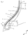
- the Fig. 1 shows a cross section through the bead area 1 of a pneumatic vehicle tire, here a car tire of radial design.
- the car tire has a customary standard construction, with two side walls, a crown area, with a carcass 2, which is guided around the bead cores 3 and around the bead apexes 4 seated on the bead cores 3 and is guided back onto the carcass 2 as a carcass turn-up 2a, with an airtight inner layer 5, a multi-layer belt and a tread.
- a single-layer bead reinforcement 6 is arranged, which is arranged between the carcass 2 and the carcass turn-up 2a returned to the carcass 2.
- the bead reinforcement 6 directly adjoins the carcass 2 and also directly adjoins the carcass turn-up 2a.
- the reinforcements of the bead reinforcement 6 enclose an angle ⁇ of 43 ° to 46 ° with the circumferential direction.
- the bead reinforcement 6 is arranged in its lower region 7 between the bead apex 4 and the carcass 2 and in its upper region 8 between the carcass 2 and the carcass turn-up 2a.
- the upper end 9 of the chipper 6 is level with the carcass turnup 2a, whereby the upper end 9 lies within the extent of the carcass turnup 2a and is at least 7-10 mm from the carcass turnup end 2c.
- the lower end 11 of the bead reinforcement is level with the lower half of the bead apex 4, but has at least a distance 12 from the upper edge of the bead core 13 of 7-10 mm.
- the bead apex 4 has a height 14 of 15 mm, measured by a vertical which rests on the upper edge 13 of the bead core, from this upper edge 13 of the bead core 3 to the tip 15 of the bead apex 4.
- the reinforcement of the bead reinforcement 6 are monofilaments made of steel, which have a diameter of 0.35 mm.
Landscapes
- Engineering & Computer Science (AREA)
- Mechanical Engineering (AREA)
- Tires In General (AREA)
Description
- Die Erfindung betrifft einen Fahrzeugluftreifen mit einer Radialkarkasse und zwei Wulstbereichen, wobei jeder Wulstbereich einen Wulstkern und einen dem Wulstkern aufsitzenden Wulstkernreiter aufweist, wobei die Karkasse von axial innen nach axial außen um die Wulstkerne und die Wulstkernreiter herum geführt und als Karkasshochschlag auf die Karkasse rück geführt ist und wobei in jedem Wulstbereich ein einziger, in Umfangsrichtung umlaufender, einlagiger und mit Festigkeitsträgern verstärkter Wulstverstärker mit einem oberen Bereich und einem gegenüber dem oberen Bereich näher zum jeweiligen Wulstkern befindlichen unteren Bereich angeordnet ist,
wobei der Wulstverstärker in seinem oberen Bereich zwischen der Karkasse und dem auf die Karkasse rückgeführten Karkasshochschlag endet, derart, dass der Wulstverstärker sowohl unmittelbar an die Karkasse als auch unmittelbar an den Karkasshochschlag angrenzt und wobei die Festigkeitsträger des Wulstverstärkers einen Winkel α mit der Umfangsrichtung einschließen, welcher in einem Bereich von 30° bis 70° liegt. - Ein Wulstverstärker ist eine Kautschuklage, welche parallel zueinander und voneinander beanstandete Festigkeitsträger aufweist und welcher kreisringförmig im Bereich des Wulstes den Reifen umläuft.
- Ein Fahrzeugluftreifen eingangs genannter Art ist beispielsweise aus der
US 6 527 025 B1 bekannt. Der Fahrzeugluftreifen weist in jedem Wulstbereich einen Wulstverstärker auf, dessen Festigkeitsträger beispielsweise Stahlkorde oder hochmodulige Textilkorde sind, die relativ zur Umfangsrichtung unter einem Winkel von 10° bis 60°, insbesondere von bis zu 30°, verlaufen. Jeder Wulstverstärker verläuft in seinem unteren Bereich axial außenseitig des Wulstkernreiters. - Aus der
US 5 379 819 A ist ein Fahrzeugluftreifen bekannt, welcher in jedem seiner Wulstbereiche einen axial inneren und einen axial äußeren, hochmodulige Korde enthaltenden Wulstverstärker aufweist. Der axial innere Wulstverstärker ist einlagig ausgeführt und ist an der Innenseite der Karkasse zwischen dieser und der Innenschicht angeordnet. Die Korde des axial inneren Wulstverstärkers verlaufen relativ zur Reifenachse unter einem Winkel von 15° bis 50°. Der axial äußere Wulstverstärker ist zweilagig ausgeführt, wobei die in jeder Lage enthaltenen Korde unter einem Winkel von 30° bis 60° zur Umfangsrichtung verlaufen. - Ferner ist aus der
EP 2 740 615 A1 ein Fahrzeugluftreifen mit je einem Wulstverstärker in den Wulstbereichen bekannt, welcher axial außen in Bezug auf den Karkasshochschlag angeordnet ist und der Versteifung des Wulstbereiches dient. Die Festigkeitsträger des Wulstverstärkers schließen einen Winkel von 24° bis 45° mit der Umfangsrichtung ein, wodurch mit den Festigkeitsträgern des Karkasshochschlages ein Kreuzverband gebildet ist, wodurch Schubverformungen der Seitenwand reduziert werden. Dieses wirkt sich positiv auf das Handling des Fahrzeugluftreifens aus. - Aus der
US 2008/0149249 A1 ist ein weiterer Fahrzeugluftreifen bekannt, welcher gemäß einer Variante in seinen Wulstbereichen jeweils einen Wulstverstärker aufweist. Der obere Bereich jedes Wulstverstärkers endet radial innerhalb der radial inneren Gürtellage, der untere Bereich endet axial innenseitig des jeweiligen Wulstkerns. - Man ist ständig bemüht, die Schräglaufsteifigkeit von Fahrzeugluftreifen zu verbessern und die Einlauflänge zu verringern, ohne dessen übrigen Eigenschaften nachteilig zu beeinflussen. Diese beiden vorgenannten Eigenschaften verbessern bei bestimmten Fahrzeugen das Handling.
- Es ist daher die Aufgabe der Erfindung, einen Fahrzeugluftreifen zur Verfügung zu stellen, der eine verbesserte Schräglaufsteifigkeit und eine verringerte Einlauflänge bei gleichem oder verbessertem Rollwiderstand aufweist.
- Die Aufgabe wird gelöst, indem
der Wulstverstärker in seinem unteren Bereich axial innenseitig des jeweiligen Wulstkernreiters sowie zwischen dem Wulstkernreiter und der Karkasse verläuft. - Erfindungswesentlich ist, dass der Wulstverstärker zwischen der Karkasse und dem Karkasshochschlag angeordnet ist und somit eine gleichzeitige Kopplung an die Karkasse und an den Karkasshochschlag ausgebildet ist. Die Festigkeitsträger des Wulstverstärkers schließen einen Winkel α von 30° bis 70° mit der Umfangsrichtung ein, so dass ein Kreuzverband sowohl zwischen Karkasse und Wulstverstärker als auch zwischen Wulstverstärker und Karkasshochschlag gebildet ist. Durch diese zweifache Kopplung ist eine enorme Verstärkung und Versteifung des Wulstbereiches bis in die Seitenwand hinein erreicht, was sich positiv auf die Schräglaufsteifigkeit des Fahrzeugluftreifens und die Einlauflänge auswirkt. Die Schubverformungen in der Seitenwand sind reduziert. Durch beides wird ein bei bestimmten Fahrzeugen ein Handlingvorteil ohne Nachteil im Rollwiderstand erreicht. Die Länge des Karkasshochschlages oberhalb des Apex beträgt mindestens 5mm und reicht in einer bestimmten Ausführung bis unter die Gürtelkante. Die Kopplung von Karkasse, Wulstverstärker und Karkasshochschlag erfolgt mindestens über eine Länge von 20 mm.
- Vorteilhaft ist es, wenn das am oberen Bereich liegende Ende des Wulstverstärkers auf Höhe des Karkasshochschlages liegt und wenigstens einen Abstand zum Karkasshochschlagende von 7 - 10 mm aufweist. Durch die Anordnung des Wulstverstärkers zwischen der Karkasse und dem Karkasshochschlag ist die Verwindungssteifigkeit erhöht, wodurch die Seitenwand steifer ist, was sich vorteilhaft auf die Schräglaufsteifigkeit auswirkt. Der Abstand des oberen Endes des Wulstverstärkers von 7 - 10mm zum Karkasshochschlagende mindert Steifigkeitssprünge.
- Zweckmäßig ist es, wenn das am unteren Bereich liegende Ende des Wulstverstärkers auf Höhe der unteren Hälfte des Wulstkernreiters liegt, jedoch wenigstens einen Abstand zur Oberkante des Wulstkernes von 7 - 10 mm aufweist. Hierdurch ist der Wulstkernreiter zuverlässig über seine gesamte Höhe von dem Wulstverstärker bedeckt und ist während des Reifenherstellungsprozesses in seiner Lage fixiert. Den Wulstverstärker zusätzlich bis unter den Wulstkern zu führen ist nicht effektiv, denn der Wulstkern bringt bereits eine hohe Steifigkeit mit sich und somit können die Materialkosten für einen längeren Wulstverstärker eingespart werden.
- Vorteilhaft ist es, wenn der Wulstkernreiter eine Höhe ≤ 20 mm, vorzugsweise eine Höhe ≤ 15 mm aufweist, gemessen durch eine Senkrechte, welche auf der zwischen dem Wulstkernreiter und dem Wulstkern befindlichen Oberkante des Wulstkernes aufsteht und bis zur Spitze des Wulstkernreiters reicht. Der Wulstkernreiter ist vergleichsweise niedrig, wodurch an Gewicht des Reifens eingespart ist, was sich vorteilhaft auf den Rollwiderstand auswirkt. Zudem verbleibt eine vergleichsweise große Länge, über welche der Wulstverstärker mit der Karkasse und gleichzeitig mit dem Karkasshochschlag koppelt, welches für das die Schräglaufsteifigkeit vorteilhaft ist.
- Zweckmäßig ist es, wenn die Festigkeitsträger des Wulstverstärkers Monofilamente aus Stahl sind, welche einen Durchmesser von 0,25 - 0,40 mm aufweisen. Stahl weist eine höhere Steifigkeit als Text auf.
- Alternativ sind die Festigkeitsträger des Wulstverstärkers textile Korde vorzugsweise aus Nylon oder Aramid. Textilkorde sind weniger steif als Festigkeitsträger aus Stahl, textile Festigkeitsträger können jedoch einfacher verarbeitet werden, da diese flexibler sind. Bei Verwendung von textilen Korden wird die Schichtenfolge Karkasse, Wulstverstärker, Karkasshochschlag dicker. Hierdurch ist die Seitenwand vorteilhaft versteift, wodurch die Schräglaufsteifigkeit von Fahrzeugluftreifen verbessert und die Einlauflänge verringert ist.
- Vorteilhaft ist es, wenn die Festigkeitsträger des Wulstverstärkers einen Winkel α mit der Umfangsrichtung einschließen, welcher in einem Bereich von 30° bis 54° liegt. Eine Anordnung der Festigkeitsträger mit einem Winkel α im Bereich von 50° bis 54° liefert die besten Ergebnisse hinsichtlich der Schräglaufsteifigkeit und verringerter Einlauflänge.
- Der Fahrzeugluftreifen ist vorzugsweise ein PKW- oder Light Truck-Reifen.
- Weitere Merkmale, Vorteile und Einzelheiten der Erfindung werden nun anhand einer Zeichnung, die ein schematisches Ausführungsbeispiel darstellt, näher beschrieben.
- Die
Fig. 1 zeigt einen Querschnitt durch den Wulstbereich 1 eines Fahrzeugluftreifens, hier eines PKW-Reifens radialer Bauart. Der PKW-Reifen weist eine übliche Standardkonstruktion auf, mit zwei Seitenwänden, einem Kronenbereich, mit einer Karkasse 2, welche um die Wulstkerne 3 und um die den Wulstkernen 3 aufsitzenden Wulstkernreiter 4 herum geführt und als Karkasshochschlag 2a auf die Karkasse 2 rück geführt ist, mit einer luftdicht ausgeführten Innenschicht 5, einem mehrlagigen Gürtel und einem Laufstreifen. Im Wulstbereich 1 ist ein einlagiger Wulstverstärker 6 angeordnet, welcher zwischen der Karkasse 2 und dem auf die Karkasse 2 rückgeführten Karkasshochschlag 2a angeordnet ist. Hierdurch grenzt der Wulstverstärker 6 sowohl unmittelbar an die Karkasse 2 als auch unmittelbar an den Karkasshochschlag 2a an. Die Festigkeitsträger des Wulstverstärkers 6 schließen mit der Umfangsrichtung einen Winkel α von 43° bis 46° ein. Der Wulstverstärker 6 ist in seinem unteren Bereich 7 zwischen dem Wulstkernreiter 4 und der Karkasse 2 und in seinem oberen Bereich 8 zwischen Karkasse 2 und Karkasshochschlag 2a angeordnet. Das obere Ende 9 des Wulstverstärkers 6 liegt auf Höhe des Karkasshochschlages 2a, wodurch das obere Ende 9 innerhalb der Erstreckung des Karkasshochschlages 2a liegt und wenigstens einen Abstand 10 zum Karkasshochschlagende 2c von 7 - 10 mm aufweist. Das untere Ende 11 des Wulstverstärkers liegt auf Höhe der unteren Hälfte des Wulstkernreiters 4, weist jedoch wenigstens einen Abstand 12 zur Oberkante des Wulstkernes 13 von 7 - 10 mm auf. - Der Wulstkernreiter 4 weist eine Höhe 14 von 15 mm auf, gemessen durch eine Senkrechte, welche auf der oberen Kante 13 des Wulstkernes aufsteht, von dieser oberen Kante 13 des Wulstkernes 3 bis zur Spitze 15 des Wulstkernreiters 4. Die Festigkeitsträger des Wulstverstärkers 6 sind Monofilamente aus Stahl, welche einen Durchmesser von 0,35 mm aufweisen.
-
- 1
- Wulstbereich
- 2
- Karkasse
- 2a
- Karkasshochschlag
- 2c
- Karkasshochschlagende
- 3
- Wulstkern
- 4
- Wulstkernreiter
- 5
- Innenschicht
- 6
- Wulstverstärker
- 7
- Unterer Bereich des Wulstverstärkers
- 8
- Oberer Bereich des Wulstverstärkers
- 9
- Oberes Ende des Wulstverstärkers
- 10
- Abstand
- 11
- Unteres Ende des Wulstverstärkers
- 12
- Abstand
- 13
- Oberkante des Wulstkerns
- 14
- Höhe des Wulstkernreiters
- 15
- Spitze des Wulstkernreiters
- rR
- radiale Richtung
- aR
- axiale Richtung
Claims (7)
- Fahrzeugluftreifen mit einer Radialkarkasse (2) und zwei Wulstbereichen (1), wobei jeder Wulstbereich (1) einen Wulstkern (3) und einen dem Wulstkern (3) aufsitzenden Wulstkernreiter (4) aufweist, wobei die Karkasse (2) von axial innen nach axial außen um die Wulstkerne (3) und die Wulstkernreiter (4) herum geführt und als Karkasshochschlag (2a) auf die Karkasse (2) rück geführt ist und wobei in jedem Wulstbereich (1) ein einziger, in Umfangsrichtung umlaufender, einlagiger und mit Festigkeitsträgern verstärkter Wulstverstärker (6) mit einem oberen Bereich (8) und einem gegenüber dem oberen Bereich (8) näher zum jeweiligen Wulstkern (3) befindlichen unteren Bereich (7) angeordnet ist,
wobei der Wulstverstärker (6) in seinem oberen Bereich (8) zwischen der Karkasse (2) und dem auf die Karkasse (2) rückgeführten Karkasshochschlag (2a) endet, derart, dass der Wulstverstärker (6) sowohl unmittelbar an die Karkasse (2) als auch unmittelbar an den Karkasshochschlag (2a) angrenzt und wobei die Festigkeitsträger des Wulstverstärkers (6) einen Winkel α mit der Umfangsrichtung einschließen, welcher in einem Bereich von 30° bis 70° liegt,
dadurch gekennzeichnet,
dass der Wulstverstärker (6) in seinem unteren Bereich (7) axial innenseitig des jeweiligen Wulstkernreiters (4) sowie zwischen dem Wulstkernreiter (4) und der Karkasse (2) verläuft. - Fahrzeugluftreifen nach Anspruch 1, dadurch gekennzeichnet, dass das am oberen Bereich (8) liegende Ende des Wulstverstärkers (9) auf Höhe des Karkasshochschlages (2a) liegt und wenigstens einen Abstand (10) zum Karkasshochschlagende (2c) von 7 - 10 mm aufweist, gemessen in radialer Richtung.
- Fahrzeugluftreifen nach Anspruch 2, dadurch gekennzeichnet, dass das am unteren Bereich (7) liegende Ende des Wulstverstärkers (11) auf Höhe der unteren Hälfte des Wulstkernreiters (4) liegt, jedoch wenigstens einen Abstand (12) zur Oberkante des Wulstkernes (13) von 7 - 10 mm aufweist, gemessen in radialer Richtung.
- Fahrzeugluftreifen nach einem oder mehreren der vorangehenden Ansprüche, dadurch gekennzeichnet, dass der Wulstkernreiter (4) eine Höhe (14) ≤ 20 mm, vorzugsweise eine Höhe (14) ≤ 15 mm, aufweist, gemessen durch eine Senkrechte, welche auf der zwischen dem Wulstkernreiter (4) und dem Wulstkern (3) befindlichen Oberkante des Wulstkernes (13) aufsteht und bis zur Spitze des Wulstkernreiters (15) reicht.
- Fahrzeugluftreifen nach einem oder mehreren der vorangehenden Ansprüche, dadurch gekennzeichnet, dass die Festigkeitsträger des Wulstverstärkers (6) Monofilamente aus Stahl sind, welche einen Durchmesser von 0,25 - 0,40 mm aufweisen.
- Fahrzeugluftreifen nach einem oder mehreren der vorangehenden Ansprüche 1 - 4, dadurch gekennzeichnet, dass die Festigkeitsträger des Wulstverstärkers (6) textile Korde vorzugsweise aus Nylon oder Aramid sind.
- Fahrzeugluftreifen nach einem oder mehreren der vorangehenden Ansprüche, dadurch gekennzeichnet, dass die Festigkeitsträger des Wulstverstärkers (6) einen Winkel α mit der Umfangsrichtung einschließen, welcher in einem Bereich von 30° bis 54° liegt.
Applications Claiming Priority (1)
| Application Number | Priority Date | Filing Date | Title |
|---|---|---|---|
| DE102017207216.4A DE102017207216A1 (de) | 2017-04-28 | 2017-04-28 | Fahrzeugluftreifen |
Publications (2)
| Publication Number | Publication Date |
|---|---|
| EP3395590A1 EP3395590A1 (de) | 2018-10-31 |
| EP3395590B1 true EP3395590B1 (de) | 2020-09-30 |
Family
ID=61163521
Family Applications (1)
| Application Number | Title | Priority Date | Filing Date |
|---|---|---|---|
| EP18155018.7A Active EP3395590B1 (de) | 2017-04-28 | 2018-02-05 | Fahrzeugluftreifen |
Country Status (2)
| Country | Link |
|---|---|
| EP (1) | EP3395590B1 (de) |
| DE (1) | DE102017207216A1 (de) |
Families Citing this family (1)
| Publication number | Priority date | Publication date | Assignee | Title |
|---|---|---|---|---|
| DE102021206626A1 (de) * | 2021-06-25 | 2022-12-29 | Continental Reifen Deutschland Gmbh | Fahrzeugluftreifen aufweisend eine Karkasslage |
Citations (1)
| Publication number | Priority date | Publication date | Assignee | Title |
|---|---|---|---|---|
| US20080149249A1 (en) * | 2005-06-06 | 2008-06-26 | Rahier Christophe B | Tire With Sidewall Reinforcement |
Family Cites Families (3)
| Publication number | Priority date | Publication date | Assignee | Title |
|---|---|---|---|---|
| JP2870703B2 (ja) * | 1990-11-28 | 1999-03-17 | 住友ゴム工業 株式会社 | 空気入りタイヤ |
| US6527025B1 (en) * | 1998-09-11 | 2003-03-04 | Sumitomo Rubber Industries, Ltd. | Tubeless tire |
| DE102012112031A1 (de) | 2012-12-10 | 2014-06-12 | Continental Reifen Deutschland Gmbh | Fahrzeugluftreifen |
-
2017
- 2017-04-28 DE DE102017207216.4A patent/DE102017207216A1/de not_active Withdrawn
-
2018
- 2018-02-05 EP EP18155018.7A patent/EP3395590B1/de active Active
Patent Citations (1)
| Publication number | Priority date | Publication date | Assignee | Title |
|---|---|---|---|---|
| US20080149249A1 (en) * | 2005-06-06 | 2008-06-26 | Rahier Christophe B | Tire With Sidewall Reinforcement |
Also Published As
| Publication number | Publication date |
|---|---|
| DE102017207216A1 (de) | 2018-10-31 |
| EP3395590A1 (de) | 2018-10-31 |
Similar Documents
| Publication | Publication Date | Title |
|---|---|---|
| DE69719855T2 (de) | Radialer LKW-Reifen | |
| DE69828584T2 (de) | Radialreifen für schwerfahrzeuge | |
| EP2536576B1 (de) | Fahrzeugluftreifen | |
| EP2560828B1 (de) | Fahrzeugluftreifen | |
| EP3145729B1 (de) | Fahrzeugluftreifen | |
| EP3083278B1 (de) | Fahrzeugluftreifen | |
| DE102010016550A1 (de) | Fahrzeugluftreifen | |
| DE102011001228A1 (de) | Fahrzeugluftreifen | |
| EP2740615B1 (de) | Fahrzeugluftreifen | |
| EP3088209B1 (de) | Fahrzeugluftreifen | |
| EP3061627B1 (de) | Nutzfahrzeugreifen mit niedriger querschnittshöhe | |
| EP2979905B1 (de) | Fahrzeugluftreifen | |
| EP3395590A1 (de) | Fahrzeugluftreifen | |
| EP3374202B1 (de) | Fahrzeugluftreifen | |
| EP3433110B1 (de) | Fahrzeugluftreifen | |
| EP3140132B1 (de) | Fahrzeugluftreifen | |
| DE102014207193B4 (de) | Fahrzeugluftreifen | |
| EP1982849B1 (de) | Fahrzeugluftreifen mit Notlaufeigenschaften | |
| DE102016204924A1 (de) | Fahrzeugluftreifen | |
| EP3041690B1 (de) | Fahrzeugluftreifen | |
| EP1535761B1 (de) | Fahrzeugluftreifen | |
| DE10351587A1 (de) | Fahrzeugluftreifen | |
| EP2078622B1 (de) | Fahrzeugluftreifen | |
| EP2889161B1 (de) | Fahrzeugluftreifen | |
| DE102018215196A1 (de) | Fahrzeugluftreifen |
Legal Events
| Date | Code | Title | Description |
|---|---|---|---|
| PUAI | Public reference made under article 153(3) epc to a published international application that has entered the european phase |
Free format text: ORIGINAL CODE: 0009012 |
|
| STAA | Information on the status of an ep patent application or granted ep patent |
Free format text: STATUS: THE APPLICATION HAS BEEN PUBLISHED |
|
| AK | Designated contracting states |
Kind code of ref document: A1 Designated state(s): AL AT BE BG CH CY CZ DE DK EE ES FI FR GB GR HR HU IE IS IT LI LT LU LV MC MK MT NL NO PL PT RO RS SE SI SK SM TR |
|
| AX | Request for extension of the european patent |
Extension state: BA ME |
|
| STAA | Information on the status of an ep patent application or granted ep patent |
Free format text: STATUS: REQUEST FOR EXAMINATION WAS MADE |
|
| 17P | Request for examination filed |
Effective date: 20190430 |
|
| RBV | Designated contracting states (corrected) |
Designated state(s): AL AT BE BG CH CY CZ DE DK EE ES FI FR GB GR HR HU IE IS IT LI LT LU LV MC MK MT NL NO PL PT RO RS SE SI SK SM TR |
|
| STAA | Information on the status of an ep patent application or granted ep patent |
Free format text: STATUS: EXAMINATION IS IN PROGRESS |
|
| 17Q | First examination report despatched |
Effective date: 20190813 |
|
| GRAP | Despatch of communication of intention to grant a patent |
Free format text: ORIGINAL CODE: EPIDOSNIGR1 |
|
| STAA | Information on the status of an ep patent application or granted ep patent |
Free format text: STATUS: GRANT OF PATENT IS INTENDED |
|
| INTG | Intention to grant announced |
Effective date: 20200421 |
|
| GRAJ | Information related to disapproval of communication of intention to grant by the applicant or resumption of examination proceedings by the epo deleted |
Free format text: ORIGINAL CODE: EPIDOSDIGR1 |
|
| STAA | Information on the status of an ep patent application or granted ep patent |
Free format text: STATUS: EXAMINATION IS IN PROGRESS |
|
| GRAP | Despatch of communication of intention to grant a patent |
Free format text: ORIGINAL CODE: EPIDOSNIGR1 |
|
| STAA | Information on the status of an ep patent application or granted ep patent |
Free format text: STATUS: GRANT OF PATENT IS INTENDED |
|
| INTC | Intention to grant announced (deleted) | ||
| GRAS | Grant fee paid |
Free format text: ORIGINAL CODE: EPIDOSNIGR3 |
|
| INTG | Intention to grant announced |
Effective date: 20200729 |
|
| GRAA | (expected) grant |
Free format text: ORIGINAL CODE: 0009210 |
|
| STAA | Information on the status of an ep patent application or granted ep patent |
Free format text: STATUS: THE PATENT HAS BEEN GRANTED |
|
| AK | Designated contracting states |
Kind code of ref document: B1 Designated state(s): AL AT BE BG CH CY CZ DE DK EE ES FI FR GB GR HR HU IE IS IT LI LT LU LV MC MK MT NL NO PL PT RO RS SE SI SK SM TR |
|
| REG | Reference to a national code |
Ref country code: GB Ref legal event code: FG4D Free format text: NOT ENGLISH Ref country code: CH Ref legal event code: EP |
|
| REG | Reference to a national code |
Ref country code: AT Ref legal event code: REF Ref document number: 1318438 Country of ref document: AT Kind code of ref document: T Effective date: 20201015 |
|
| REG | Reference to a national code |
Ref country code: DE Ref legal event code: R096 Ref document number: 502018002569 Country of ref document: DE |
|
| REG | Reference to a national code |
Ref country code: IE Ref legal event code: FG4D Free format text: LANGUAGE OF EP DOCUMENT: GERMAN |
|
| RAP2 | Party data changed (patent owner data changed or rights of a patent transferred) |
Owner name: CONTINENTAL REIFEN DEUTSCHLAND GMBH |
|
| PG25 | Lapsed in a contracting state [announced via postgrant information from national office to epo] |
Ref country code: SE Free format text: LAPSE BECAUSE OF FAILURE TO SUBMIT A TRANSLATION OF THE DESCRIPTION OR TO PAY THE FEE WITHIN THE PRESCRIBED TIME-LIMIT Effective date: 20200930 Ref country code: NO Free format text: LAPSE BECAUSE OF FAILURE TO SUBMIT A TRANSLATION OF THE DESCRIPTION OR TO PAY THE FEE WITHIN THE PRESCRIBED TIME-LIMIT Effective date: 20201230 Ref country code: GR Free format text: LAPSE BECAUSE OF FAILURE TO SUBMIT A TRANSLATION OF THE DESCRIPTION OR TO PAY THE FEE WITHIN THE PRESCRIBED TIME-LIMIT Effective date: 20201231 Ref country code: BG Free format text: LAPSE BECAUSE OF FAILURE TO SUBMIT A TRANSLATION OF THE DESCRIPTION OR TO PAY THE FEE WITHIN THE PRESCRIBED TIME-LIMIT Effective date: 20201230 Ref country code: HR Free format text: LAPSE BECAUSE OF FAILURE TO SUBMIT A TRANSLATION OF THE DESCRIPTION OR TO PAY THE FEE WITHIN THE PRESCRIBED TIME-LIMIT Effective date: 20200930 Ref country code: FI Free format text: LAPSE BECAUSE OF FAILURE TO SUBMIT A TRANSLATION OF THE DESCRIPTION OR TO PAY THE FEE WITHIN THE PRESCRIBED TIME-LIMIT Effective date: 20200930 |
|
| PG25 | Lapsed in a contracting state [announced via postgrant information from national office to epo] |
Ref country code: RS Free format text: LAPSE BECAUSE OF FAILURE TO SUBMIT A TRANSLATION OF THE DESCRIPTION OR TO PAY THE FEE WITHIN THE PRESCRIBED TIME-LIMIT Effective date: 20200930 Ref country code: LV Free format text: LAPSE BECAUSE OF FAILURE TO SUBMIT A TRANSLATION OF THE DESCRIPTION OR TO PAY THE FEE WITHIN THE PRESCRIBED TIME-LIMIT Effective date: 20200930 |
|
| REG | Reference to a national code |
Ref country code: NL Ref legal event code: MP Effective date: 20200930 |
|
| REG | Reference to a national code |
Ref country code: LT Ref legal event code: MG4D |
|
| PG25 | Lapsed in a contracting state [announced via postgrant information from national office to epo] |
Ref country code: EE Free format text: LAPSE BECAUSE OF FAILURE TO SUBMIT A TRANSLATION OF THE DESCRIPTION OR TO PAY THE FEE WITHIN THE PRESCRIBED TIME-LIMIT Effective date: 20200930 Ref country code: CZ Free format text: LAPSE BECAUSE OF FAILURE TO SUBMIT A TRANSLATION OF THE DESCRIPTION OR TO PAY THE FEE WITHIN THE PRESCRIBED TIME-LIMIT Effective date: 20200930 Ref country code: RO Free format text: LAPSE BECAUSE OF FAILURE TO SUBMIT A TRANSLATION OF THE DESCRIPTION OR TO PAY THE FEE WITHIN THE PRESCRIBED TIME-LIMIT Effective date: 20200930 Ref country code: PT Free format text: LAPSE BECAUSE OF FAILURE TO SUBMIT A TRANSLATION OF THE DESCRIPTION OR TO PAY THE FEE WITHIN THE PRESCRIBED TIME-LIMIT Effective date: 20210201 Ref country code: LT Free format text: LAPSE BECAUSE OF FAILURE TO SUBMIT A TRANSLATION OF THE DESCRIPTION OR TO PAY THE FEE WITHIN THE PRESCRIBED TIME-LIMIT Effective date: 20200930 Ref country code: SM Free format text: LAPSE BECAUSE OF FAILURE TO SUBMIT A TRANSLATION OF THE DESCRIPTION OR TO PAY THE FEE WITHIN THE PRESCRIBED TIME-LIMIT Effective date: 20200930 |
|
| PG25 | Lapsed in a contracting state [announced via postgrant information from national office to epo] |
Ref country code: AL Free format text: LAPSE BECAUSE OF FAILURE TO SUBMIT A TRANSLATION OF THE DESCRIPTION OR TO PAY THE FEE WITHIN THE PRESCRIBED TIME-LIMIT Effective date: 20200930 Ref country code: ES Free format text: LAPSE BECAUSE OF FAILURE TO SUBMIT A TRANSLATION OF THE DESCRIPTION OR TO PAY THE FEE WITHIN THE PRESCRIBED TIME-LIMIT Effective date: 20200930 Ref country code: IS Free format text: LAPSE BECAUSE OF FAILURE TO SUBMIT A TRANSLATION OF THE DESCRIPTION OR TO PAY THE FEE WITHIN THE PRESCRIBED TIME-LIMIT Effective date: 20210130 Ref country code: PL Free format text: LAPSE BECAUSE OF FAILURE TO SUBMIT A TRANSLATION OF THE DESCRIPTION OR TO PAY THE FEE WITHIN THE PRESCRIBED TIME-LIMIT Effective date: 20200930 |
|
| PG25 | Lapsed in a contracting state [announced via postgrant information from national office to epo] |
Ref country code: SK Free format text: LAPSE BECAUSE OF FAILURE TO SUBMIT A TRANSLATION OF THE DESCRIPTION OR TO PAY THE FEE WITHIN THE PRESCRIBED TIME-LIMIT Effective date: 20200930 Ref country code: NL Free format text: LAPSE BECAUSE OF FAILURE TO SUBMIT A TRANSLATION OF THE DESCRIPTION OR TO PAY THE FEE WITHIN THE PRESCRIBED TIME-LIMIT Effective date: 20200930 |
|
| REG | Reference to a national code |
Ref country code: DE Ref legal event code: R097 Ref document number: 502018002569 Country of ref document: DE |
|
| PLBE | No opposition filed within time limit |
Free format text: ORIGINAL CODE: 0009261 |
|
| STAA | Information on the status of an ep patent application or granted ep patent |
Free format text: STATUS: NO OPPOSITION FILED WITHIN TIME LIMIT |
|
| PG25 | Lapsed in a contracting state [announced via postgrant information from national office to epo] |
Ref country code: DK Free format text: LAPSE BECAUSE OF FAILURE TO SUBMIT A TRANSLATION OF THE DESCRIPTION OR TO PAY THE FEE WITHIN THE PRESCRIBED TIME-LIMIT Effective date: 20200930 |
|
| 26N | No opposition filed |
Effective date: 20210701 |
|
| PG25 | Lapsed in a contracting state [announced via postgrant information from national office to epo] |
Ref country code: MC Free format text: LAPSE BECAUSE OF FAILURE TO SUBMIT A TRANSLATION OF THE DESCRIPTION OR TO PAY THE FEE WITHIN THE PRESCRIBED TIME-LIMIT Effective date: 20200930 |
|
| REG | Reference to a national code |
Ref country code: BE Ref legal event code: MM Effective date: 20210228 |
|
| PG25 | Lapsed in a contracting state [announced via postgrant information from national office to epo] |
Ref country code: LI Free format text: LAPSE BECAUSE OF NON-PAYMENT OF DUE FEES Effective date: 20210228 Ref country code: LU Free format text: LAPSE BECAUSE OF NON-PAYMENT OF DUE FEES Effective date: 20210205 Ref country code: CH Free format text: LAPSE BECAUSE OF NON-PAYMENT OF DUE FEES Effective date: 20210228 |
|
| PG25 | Lapsed in a contracting state [announced via postgrant information from national office to epo] |
Ref country code: SI Free format text: LAPSE BECAUSE OF FAILURE TO SUBMIT A TRANSLATION OF THE DESCRIPTION OR TO PAY THE FEE WITHIN THE PRESCRIBED TIME-LIMIT Effective date: 20200930 |
|
| PG25 | Lapsed in a contracting state [announced via postgrant information from national office to epo] |
Ref country code: IE Free format text: LAPSE BECAUSE OF NON-PAYMENT OF DUE FEES Effective date: 20210205 |
|
| PG25 | Lapsed in a contracting state [announced via postgrant information from national office to epo] |
Ref country code: IS Free format text: LAPSE BECAUSE OF FAILURE TO SUBMIT A TRANSLATION OF THE DESCRIPTION OR TO PAY THE FEE WITHIN THE PRESCRIBED TIME-LIMIT Effective date: 20210130 |
|
| PG25 | Lapsed in a contracting state [announced via postgrant information from national office to epo] |
Ref country code: BE Free format text: LAPSE BECAUSE OF NON-PAYMENT OF DUE FEES Effective date: 20210228 |
|
| GBPC | Gb: european patent ceased through non-payment of renewal fee |
Effective date: 20220205 |
|
| PG25 | Lapsed in a contracting state [announced via postgrant information from national office to epo] |
Ref country code: GB Free format text: LAPSE BECAUSE OF NON-PAYMENT OF DUE FEES Effective date: 20220205 |
|
| PG25 | Lapsed in a contracting state [announced via postgrant information from national office to epo] |
Ref country code: CY Free format text: LAPSE BECAUSE OF FAILURE TO SUBMIT A TRANSLATION OF THE DESCRIPTION OR TO PAY THE FEE WITHIN THE PRESCRIBED TIME-LIMIT Effective date: 20200930 |
|
| PG25 | Lapsed in a contracting state [announced via postgrant information from national office to epo] |
Ref country code: HU Free format text: LAPSE BECAUSE OF FAILURE TO SUBMIT A TRANSLATION OF THE DESCRIPTION OR TO PAY THE FEE WITHIN THE PRESCRIBED TIME-LIMIT; INVALID AB INITIO Effective date: 20180205 |
|
| REG | Reference to a national code |
Ref country code: DE Ref legal event code: R081 Ref document number: 502018002569 Country of ref document: DE Owner name: CONTINENTAL REIFEN DEUTSCHLAND GMBH, DE Free format text: FORMER OWNER: CONTINENTAL REIFEN DEUTSCHLAND GMBH, 30165 HANNOVER, DE |
|
| REG | Reference to a national code |
Ref country code: AT Ref legal event code: MM01 Ref document number: 1318438 Country of ref document: AT Kind code of ref document: T Effective date: 20230205 |
|
| PG25 | Lapsed in a contracting state [announced via postgrant information from national office to epo] |
Ref country code: AT Free format text: LAPSE BECAUSE OF NON-PAYMENT OF DUE FEES Effective date: 20230205 |
|
| PG25 | Lapsed in a contracting state [announced via postgrant information from national office to epo] |
Ref country code: MK Free format text: LAPSE BECAUSE OF FAILURE TO SUBMIT A TRANSLATION OF THE DESCRIPTION OR TO PAY THE FEE WITHIN THE PRESCRIBED TIME-LIMIT Effective date: 20200930 Ref country code: AT Free format text: LAPSE BECAUSE OF NON-PAYMENT OF DUE FEES Effective date: 20230205 |
|
| PGFP | Annual fee paid to national office [announced via postgrant information from national office to epo] |
Ref country code: IT Payment date: 20240228 Year of fee payment: 7 |
|
| PG25 | Lapsed in a contracting state [announced via postgrant information from national office to epo] |
Ref country code: MT Free format text: LAPSE BECAUSE OF FAILURE TO SUBMIT A TRANSLATION OF THE DESCRIPTION OR TO PAY THE FEE WITHIN THE PRESCRIBED TIME-LIMIT Effective date: 20200930 |
|
| PG25 | Lapsed in a contracting state [announced via postgrant information from national office to epo] |
Ref country code: TR Free format text: LAPSE BECAUSE OF FAILURE TO SUBMIT A TRANSLATION OF THE DESCRIPTION OR TO PAY THE FEE WITHIN THE PRESCRIBED TIME-LIMIT Effective date: 20200930 |
|
| PG25 | Lapsed in a contracting state [announced via postgrant information from national office to epo] |
Ref country code: IT Free format text: LAPSE BECAUSE OF NON-PAYMENT OF DUE FEES Effective date: 20250205 |
|
| PGFP | Annual fee paid to national office [announced via postgrant information from national office to epo] |
Ref country code: DE Payment date: 20260228 Year of fee payment: 9 |
|
| PGFP | Annual fee paid to national office [announced via postgrant information from national office to epo] |
Ref country code: AT Payment date: 20260410 Year of fee payment: 5 |
|
| PGFP | Annual fee paid to national office [announced via postgrant information from national office to epo] |
Ref country code: FR Payment date: 20260218 Year of fee payment: 9 |