EP3395538A1 - Vorrichtung zur druckluftsteuerung - Google Patents
Vorrichtung zur druckluftsteuerung Download PDFInfo
- Publication number
- EP3395538A1 EP3395538A1 EP18169476.1A EP18169476A EP3395538A1 EP 3395538 A1 EP3395538 A1 EP 3395538A1 EP 18169476 A EP18169476 A EP 18169476A EP 3395538 A1 EP3395538 A1 EP 3395538A1
- Authority
- EP
- European Patent Office
- Prior art keywords
- control
- control unit
- housing
- valve modules
- block
- Prior art date
- Legal status (The legal status is an assumption and is not a legal conclusion. Google has not performed a legal analysis and makes no representation as to the accuracy of the status listed.)
- Granted
Links
Images



Classifications
-
- B—PERFORMING OPERATIONS; TRANSPORTING
- B29—WORKING OF PLASTICS; WORKING OF SUBSTANCES IN A PLASTIC STATE IN GENERAL
- B29C—SHAPING OR JOINING OF PLASTICS; SHAPING OF MATERIAL IN A PLASTIC STATE, NOT OTHERWISE PROVIDED FOR; AFTER-TREATMENT OF THE SHAPED PRODUCTS, e.g. REPAIRING
- B29C49/00—Blow-moulding, i.e. blowing a preform or parison to a desired shape within a mould; Apparatus therefor
- B29C49/42—Component parts, details or accessories; Auxiliary operations
- B29C49/4289—Valve constructions or configurations, e.g. arranged to reduce blowing fluid consumption
-
- B—PERFORMING OPERATIONS; TRANSPORTING
- B29—WORKING OF PLASTICS; WORKING OF SUBSTANCES IN A PLASTIC STATE IN GENERAL
- B29C—SHAPING OR JOINING OF PLASTICS; SHAPING OF MATERIAL IN A PLASTIC STATE, NOT OTHERWISE PROVIDED FOR; AFTER-TREATMENT OF THE SHAPED PRODUCTS, e.g. REPAIRING
- B29C49/00—Blow-moulding, i.e. blowing a preform or parison to a desired shape within a mould; Apparatus therefor
- B29C49/42—Component parts, details or accessories; Auxiliary operations
- B29C49/78—Measuring, controlling or regulating
-
- B—PERFORMING OPERATIONS; TRANSPORTING
- B29—WORKING OF PLASTICS; WORKING OF SUBSTANCES IN A PLASTIC STATE IN GENERAL
- B29L—INDEXING SCHEME ASSOCIATED WITH SUBCLASS B29C, RELATING TO PARTICULAR ARTICLES
- B29L2031/00—Other particular articles
- B29L2031/712—Containers; Packaging elements or accessories, Packages
- B29L2031/7158—Bottles
Definitions
- the present invention relates to a device for compressed air control, in particular for the compressed air control of stretch blow molding. According to a further aspect, the invention relates to a stretch blow molding device which has such a device for compressed air control.
- Stretch blow molding is a process for the production of plastic containers made of thermoplastic materials, such as PET, PVC or PP.
- the method is used in particular for the production of PET bottles.
- preforms are tempered in a first process step to a processing temperature of 90-120 °, so that the preform can be plastically deformed in a second step by stretch blow molding.
- a stretch rod is inserted into an opening of the preform in order to mechanically stretch it in the longitudinal direction.
- a pneumatic pressure molding in which the PET material is pressed against inner walls of a blow mold.
- a pre-blowing pressure is initially provided, which serves to press the PET material against the inner wall of the blow mold.
- a main blowing pressure which is many times higher than the pre-blowing pressure, is provided to produce the final shape of the PET container and completely transfer the structure of the blow mold to the PET material.
- valves are used to provide precise control of the pre-blow and main blow pressures for a variety of stretch blow stations. It is also known to provide the individual valves as separate valve modules on a blowing block. This blowing block is fixed firmly on a rotating blowing wheel of a so-called "ROTARY" stretch blow molding machine. Such bladders allow the control of stretch blow stations from a central location. This facilitates both the construction and the later operation of the stretch blow molding plant. In particular, a particularly compact design is made possible by the blow blocks, since the individual designed as a solenoid valve modules are arranged side by side with very little distance.
- the individual valve modules of the black block can be individually controlled by a central control unit.
- known devices for compressed air control on a plurality of separate control lines which connect the control unit with a housing of the black block. It is a known problem that the plurality of control lines obstructs the movement of the compressed air control device and leads to the abrasion of the control lines / cables. This is the case in particular because the blowing block rotates with the blowing wheel, which causes centrifugal forces which also act on control lines between the control unit and the individual valve modules and cause them to oscillate. The oscillating movement results in a fomentation / abrasion of the control lines on the housing of the blow block, which considerably reduces the service life of known devices.
- the object of a device for compressed air control and a stretch blower indicate, which avoids the disadvantages of known solutions.
- the present invention proposes a device for compressed air control of stretch blow molding according to the independent claim 1 before.
- the invention relates to a device for compressed air control of stretch blow molding devices which has a blow block with a housing and at least two valve modules.
- the device also has a control unit, which is electrically connectable to each of the at least two valve modules via a respective separate control line.
- the separate control lines are located exclusively within the housing of the black block.
- the control unit is used to individually control the individual valve modules. For this purpose, an individual control signal is sent by the control unit, via the separate control lines, to the respective valve module.
- the solution according to the invention has the advantage that the multiplicity of control lines, which are connected to the individual valve modules, run within the housing and can thus be moved together with it.
- the individual control lines therefore do not hinder the movement of the black block.
- the blow block may thus have a single control port connected to a single control line rather than connecting the blow block to a separate control line per valve module.
- the number of control lines which are located on the outside of the bladder housing is thereby significantly reduced.
- the at least two valve modules are detachably connected to the housing.
- the valve modules are accordingly quickly and easily replaceable for maintenance purposes. Since the control lines run within the housing of the black block, it is also not necessary to replace the valve modules, the control lines to first remove from the valve modules before replacement. Rather, the control lines remain within the black block, regardless of whether the control line is connected to a corresponding valve module or not.
- the separate control lines can be electrically connected via a connector with a corresponding valve module.
- the connectors may be located on an outside of the housing for this purpose. In other words, each of the separate control lines within the housing of the black block is connected to a corresponding connector. By inserting the valve module into the connector, the respective valve module is directly connected to the correct control line.
- the device has a first control line between the control unit and a first valve module and a second control line between the control unit and the second valve module.
- the control unit can be arranged outside the housing of the black block and connected to the separate control lines via a field bus or a multipole cable.
- the control signals of Transfer control unit via a single control cable to the blower block. Only within the black block are the control signals distributed to the corresponding, separate control lines in order to individually control the individual valve modules.
- a fieldbus between the external control unit and the blowing block, there is a multiplexer within the blowing block, which transmits the fieldbus signals to the separate control lines.
- a multipole cable is provided which extends between the control unit and the blowing block and, within the housing, disintegrates into separate control lines within.
- control unit is arranged within the housing, between a control input and the separate control lines. Accordingly, the control data is generated directly within the housing of the black block and distributed to the separate control lines of the individual valve modules.
- the control unit is protected by the housing.
- the control unit may be formed as a printed circuit board.
- the housing may have a cavity in which the printed circuit board is mounted freely swinging.
- the printed circuit board can be secured within the housing only at edge regions, whereby the printed circuit board is elastically deformable within the cavity. As a result, in particular damage to the printed circuit board due to vibrations of the black block are reduced or prevented.
- the device has a main control device, which is electrically connected to the control unit.
- the main controller controls the entire stretch blower unit and sends appropriate signals to the controller as soon as the blower block is activated.
- the main control device is preferably connected to the control unit by a single control line.
- a power supply line may be provided which ensures the power supply of the control unit.
- the main control device can be connected to the control unit via a control cable. If the control unit is arranged inside the housing, the latter has for this purpose a single external control connection to which the control cable can be connected. Alternatively, the main controller may be connected to the control unit via a wireless network. According to this embodiment, it is conceivable that the blowing block of the device according to the invention has no external cable connections or only one power supply connection. In other words, it is conceivable that the main controller communicates with the control unit via a WLAN network.
- the at least two valve modules can be designed as 5/2 valves. Since it is a device which is preferably provided for compressed air control for stretch blow molding operations, the valve modules are in particular pneumatic valve modules.
- the valve modules may be designed as solenoid valves, which are activated by the separate control lines within the Blasblock housing.
- a stretch blow molding apparatus having the aforementioned compressed air control apparatus.
- the stretch blow molding apparatus may include an extension piston electrically connected to an extension piston control device, the extension piston control device being connected to the main control unit.
- FIG. 1 is a schematic representation of a device according to the invention for the compressed air control of Steckblaßvorraumen refer.
- the device 10 has a blowing block 20 with a housing 21.
- a series of valve modules 23a, 23b, 23c, 23d, 23e, 23f are attached to the housing 21 of the black block 20.
- six individual valve modules 23a, 23b, 23c, 23d, 23e, 23f are shown, which are arranged detachably on an outer side of the housing 21.
- a control unit 30 is arranged outside the housing 20 and connected to the blowing block 20 via a single data cable 32.
- the data cable 32 may be a fieldbus or a multipole cable. In the embodiment according to FIG. 1 is it? at the data cable 32 to a field bus, which is connected via a plug connection 24 to the housing 21.
- a multiplexer 26 is provided, which is connected via a connecting line 25 to the connector 24.
- the multiplexer 26 converts the signals of the fieldbus data cable 32 into individual signals for the respective valve modules 23a to 23f.
- the output of the multiplexer 26 is connected in each case via separate control lines 28a to 28f to the individual valve modules 23a to 23f.
- the blowing block 20 is connected to the control unit 30 via only one data cable 32. This has the advantage that fewer data cables are arranged on the outside of the black block 20 and the latter is thereby freely movable or pivotable. This is the case in particular because the separate control lines 28a to 28f for the individual valve modules 23a to 23f run inside the housing 21 of the black block 20.
- FIG. 1 also shows a main controller 40, which is connected via a further data cable 42 to the control unit 30.
- the main controller 40 may be configured to control all operations of a stretch blower.
- the control unit 30 is designed exclusively for controlling the black block 20.
- the main controller 40 may be connected to the controller 30 via a power supply cable 44.
- control commands of the main controller 40 are forwarded to the control unit 30 via the data cable 42.
- the signal received by the blowing block 20 is sent via the plug connection 24 and the control line 25 to the multiplexer 26, which decomposes the fieldbus signal into individual signals for the different valve modules 23a to 23f.
- a further embodiment of the device according to the invention for compressed air control can the schematic representation according to FIG. 2 be removed.
- the device 100 according to FIG. 2 differs from the device 10 according to FIG. 1 essentially, the control unit 130 is disposed within the housing 121 of the black block 120. Similar to FIG. 1 is also the control unit 130 of in FIG. 2 device 100 connected to a main controller 140 via a single data cable 142. In this embodiment, the data cable 142 between the main controller 140 and the controller 130 is connected to the single connector 124. Since the control unit 130 according to the FIG. 2 Located directly in the housing 121 of the black block 120 may be placed on a separate multiplexer, like this one in FIG FIG. 1 was shown to be omitted. Rather, the signals of the control unit 130 are transmitted directly via separate control lines 128a to 128f to the individual valve modules 123a to 123f.
- the separate control lines 128a to 128f extend exclusively within the housing 121 of the black block 120.
- a single data cable 142 connected to the outside of the housing 121 only a single data cable 142 connected to the outside of the housing 121.
- An optional power supply cable 144 may be disposed between the main controller 140 and the controller 130 located in the housing 121.
- the control unit 130 according to FIG. 2 may be formed, for example, as a printed circuit board, as with reference to the FIG. 4 will be described in more detail.
- FIG. 2 shows perspective views of a blowing block 220, as described, for example, in the exclamation in accordance with FIG FIG. 2 can be used.
- the blower block 220 has a housing 221 which has a single plug connection 224.
- the connector 224 may be connected to a data cable (not shown) which establishes an electrical connection to the main controller (not shown).
- the housing 221 six valve modules 223a to 223f are releasably attached. In particular, the valve modules are insertable into the housing 221 and can thus be quickly and easily released from the blowing block 220 for maintenance purposes.
- the blowing block 220 has a plurality of compressed air ports 229a to 229f, which are connected by the housing 221 of the black block 220 with different air inlets and air outlets of the valve modules 223a to 223f.
- a muffler 222 is also attached to the blowing block 220 and serves to reduce the noise of the black block during operation.
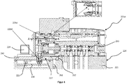
- FIG. 4 A sectional view through part of the black block 220 and the valve module 223d is the FIG. 4 refer to.
- the control unit 230 is provided within the housing 221 of the black block 220.
- the control unit 230 is arranged for this purpose within a cavity 227 of the housing 221. Only an edge region of the control unit 230, which is designed as a printed circuit board, is fastened in the cavity 227. The remaining part of the printed circuit board is freely movable, ie elastically deformable, stored within the cavity 227. Accordingly, the control unit 230 can easily compensate for vibrations of the black block 220.
- the control unit 230 is connected via a control line 225 to the plug connection 224. At another end, the control unit 230 is in contact with one of the separate control lines 228d.
- the control line 228d connects the control unit 230 with the valve module 223d shown here.
- the valve modules 223a, 223b, 223c, 223e, 223f, not shown here are connected to the control unit 230 in the form of a printed circuit board via similar, separate control lines.
- the separate control line 228d connects the control unit 230 to a receiver module 229d disposed within the valve module 223d.
- the receiver module 229d receives the signals from the control unit 230 and controls the movement of a valve spool 250 accordingly.
- the structure and function of valve spools within the Valve modules of a blowing block is well known and requires no further explanation.
- the blowing block 220 has a detachable cover 260.
- the cover 260 is detachably connected to the housing 221 of the black block 220.
- the cover 260 is fastened to the housing 221 by a screw connection 261.
- the cover closes the cavity 227 on an outside of the housing 221 facing the valve module 223d.
- the housing 221 has a recess 262, which is matched to the dimensions of the cover 260 so that it flanges with the housing 221 and has a flat surface forms.
- the cover 260 may be removed for maintenance purposes, allowing quick and easy access to the control board 230 formed as a printed circuit board.
- FIG. 5 Another embodiment of the device according to the invention for compressed air control is in FIG. 5 shown.
- the embodiment according to FIG. 5 corresponds substantially to the embodiment according to FIG. 2 , Components with the same effect are marked with corresponding reference numerals, which are "200" relative to the FIG. 2 were increased.
- the control unit 330 is mounted within the housing 321 of the black block 320.
- the device 300 has a main controller 340, which communicates with the control unit 330.
- the transmission of data in the device 300 is achieved by a wireless network.
- the main control line 340 has a first wireless transceiver unit 341 and the control unit 330 has a second wireless transceiver unit 331.
- no control cable between the main control device 340 and the control unit 330 is required by this embodiment. Only an optional power supply line 344 may be provided between the main controller 340 and the control unit 330.
Landscapes
- Engineering & Computer Science (AREA)
- Manufacturing & Machinery (AREA)
- Mechanical Engineering (AREA)
- Fluid-Pressure Circuits (AREA)
- Blow-Moulding Or Thermoforming Of Plastics Or The Like (AREA)
Abstract
Description
- Die vorliegende Erfindung betrifft eine Vorrichtung zur Druckluftsteuerung, insbesondere zur Druckluftsteuerung von Streckblasvorrichtungen. Gemäß eines weiteren Aspekts betrifft die Erfindung eine Streckblasvorrichtung, welche eine derartige Vorrichtung zur Druckluftsteuerung aufweist.
- Streckblasen ist ein Verfahren zur Herstellung von Kunststoff-Behältern aus thermoplastischen Kunststoffen, wie PET, PVC oder PP. Das Verfahren wird insbesondere zur Herstellung von PET-Flaschen eingesetzt. Dabei werden Vorformlinge in einem ersten Verfahrensschritt auf eine Verarbeitungstemperatur von 90-120° temperiert, sodass der Vorformling in einem zweiten Arbeitsschritt durch Streckblasen plastisch verformt werden kann. Hierzu wird eine Reckstange in eine Mündung des Vorformlings eingeführt, um diesen mechanisch in Längsrichtung zu verstrecken. Anschließend erfolgt eine pneumatische Druckausformung, in welcher das PET-Material gegen Innenwände einer Blasform gepresst wird. Bei der Druckausformung wird zunächst ein Vorblasdruck bereitgestellt, welcher dazu dient das PET Material gegen die Innenwand der Blasform zu drücken. In einem zweiten Blasschritt wird ein Hauptblasdruck, welcher um ein Vielfaches höher ist als der Vorblasdruck, bereitgestellt um die endgültige Form des PET-Behälters herzustellen und die Struktur der Blasform vollständig auf das PET-Material zu übertragen.
- In den bekannten Streckblas-Vorrichtungen wird eine Vielzahl von Ventilen verwendet, um die exakte Steuerung des Vorblas- und Hauptblasdrucks für eine Vielzahl von Streckblas-Stationen zu ermöglichen. Es ist ferner bekannt, die einzelnen Ventile als separate Ventil-Module an einem Blasblock vorzusehen. Dieser Blasblock wird fest auf enem rotierenden Blasrad einer sogenannten "ROTARY" Streckblasmaschine befestigt. Derartige Blasblöcke erlauben die Steuerung der Streckblas-Stationen von einer zentralen Stelle. Dies erleichtert sowohl den Aufbau als auch den späteren Betrieb der Streckblas-Anlage. Insbesondere wird durch die Blasblöcke ein besonders kompakter Aufbau ermöglicht, da die einzelnen als Magnetventil ausgebildeten Ventil-Module mit sehr geringem Abstand nebeneinander angeordnet sind.
- Die einzelnen Ventil-Module des Blackblocks sind individuell durch eine zentrale Steuereinheit ansteuerbar. Hierzu weisen bekannte Vorrichtungen zur Druckluftsteuerung eine Vielzahl von separaten Steuerleitungen auf, welche die Steuereinheit mit einem Gehäuse des Blackblocks verbinden. Es ist ein bekanntes Problem, dass die Vielzahl von Steuerleitungen die Bewegung der Vorrichtung zur Druckluftsteuerung behindert und zum Abrieb der Steuerleitungen/-kabel führt. Dies ist insbesondere deshalb der Fall, da der Blasblock mit dem Blasrad rotiert, wodurch Fliehkräfte entstehen, die auch auf Steuerleitungen zwischen der Steuereinheit und den einzelnen Ventilmodulen wirken und diese ins Schwingen bringen. Durch die Schwingbewegung ergibt sich ein Schüren/Abrieb der Steuerleitungen am Gehäuse des Blasblocks, was die Standzeiten bekannter Vorrichtungen erheblich verringert.
- Im Hinblick auf die oben genannte Problemstellung, liegt der vorliegenden Erfindung die Aufgabe zu Grunde eine Vorrichtung zur Druckluftsteuerung sowie eine Streckblasvorrichtung anzugeben, welche die Nachteile bekannter Lösungen umgeht. Insbesondere ist es eine Aufgabe der vorliegenden Erfindung eine Vorrichtung zur Druckluftsteuerung bereitzustellen, bei welcher der Blasblock möglichst frei bewegbar ist und längere Standzeiten aufweist.
- Zur Lösung der oben genannten Aufgabe schlägt die vorliegende Erfindung eine Vorrichtung zur Druckluftsteuerung von Streckblasvorrichtungen gemäß dem unabhängigen Patentanspruch 1 vor. Insbesondere betrifft die Erfindung eine Vorrichtung zur Druckluftsteuerung von Streckblasvorrichtungen welche einen Blasblock mit einem Gehäuse sowie mindestens zwei Ventil-Modulen aufweist. Die Vorrichtung weist ferner eine Steuereinheit auf, welche über je eine separate Steuerleitung mit jedem der mindestens zwei Ventil-Module elektrisch verbindbar ist. Die separaten Steuerleitungen sind ausschließlich innerhalb des Gehäuses des Blackblocks angeordnet. Die Steuereinheit dient dazu, die einzelnen Ventil-Module individuell anzusteuern. Hierzu wird je ein individuelles Steuersignal von der Steuereinheit, über die separaten Steuerleitungen, an das jeweilige Ventil-Modul gesendet.
- Die erfindungsgemäße Lösung hat den Vorteil, dass die Vielzahl an Steuerleitungen, welche mit den einzelnen Ventil-Modulen verbunden sind innerhalb des Gehäuses verlaufen und somit gemeinsam mit diesem bewegt werden können. Die einzelnen Steuerleitungen behindern daher die Bewegung des Blackblocks nicht. Der Blasblock kann somit einen einzelnen Steueranschluss aufweisen, welcher mit einer einzigen Steuerleitung verbunden ist, anstatt den Blasblock mit einer separaten Steuerleitungen pro Ventil-Modul zu verbinden. Die Anzahl an Steuerleitungen, welche sich an der Außenseite des Blasblock-Gehäuses befinden wird hierdurch signifikant reduziert.
- Gemäß einer weiteren Ausführungsform, sind die mindestens zwei Ventil-Module lösbar mit dem Gehäuse verbunden. Die Ventil-Module sind dementsprechend zu Wartungszwecken schnell und einfach austauschbar. Da die Steuerleitungen innerhalb des Gehäuses des Blackblocks verlaufen, ist es zum Austausch der Ventil-Module auch nicht notwendig, die Steuerleitungen vor dem Austausch zunächst von den Ventil-Modulen zu entfernen. Vielmehr verbleiben die Steuerleitungen innerhalb des Blackblocks, unabhängig davon ob die Steuerleitung mit einem korrespondierenden Ventil-Modul verbunden ist oder nicht. Die separaten Steuerleitungen können über einen Steckverbinder elektrisch mit einem korrespondierenden Ventil-Modul verbunden sein. Die Steckverbinder können sich hierzu an einer Außenseite des Gehäuses befinden. Mit anderen Worten ist jede der separaten Steuerleitungen innerhalb des Gehäuses des Blackblocks an einen korrespondierenden Steckverbinder angeschlossen. Durch Einstecken des Ventil-Moduls in den Steckverbinder ist das jeweilige Ventil-Modul direkt mit der korrekten Steuerleitung verbunden.
- Nach einer weiteren Ausführungsform weist die Vorrichtung eine erste Steuerleitung zwischen der Steuereinheit und einem ersten Ventil-Modul sowie eine zweite Steuerleitung zwischen der Steuereinheit und dem zweiten Ventil-Modul auf.
- Die Steuereinheit kann außerhalb des Gehäuses des Blackblocks angeordnet und über einen Feldbus oder ein Multipol-Kabel mit den separaten Steuerleitungen verbunden sein. Gemäß dieser Ausführungsform werden die Steuersignale der Steuereinheit über ein einzelnes Steuerkabel an den Blasblock übertragen. Erst innerhalb des Blackblocks werden die Steuersignale auf die entsprechenden, separaten Steuerleitungen verteilt, um die einzelnen Ventil-Module individuell anzusteuern. Im Falle eines Feldbuses zwischen der externen Steuereinheit und dem Blasblock, befindet sich ein Multiplexer innerhalb des Blasblocks, welcher die Signale des Feldbusses auf die separaten Steuerleitungen überträgt. Alternativ ist ein Multipol-Kabel vorgesehen, welches sich zwischen der Steuereinheit und des Blasblocks erstreckt und, innerhalb des Gehäuses, in separate Steuerleitungen innerhalb zerfällt.
- Gemäß einer alternativen Ausführungsform ist die Steuereinheit innerhalb des Gehäuses, zwischen einem Steuereingang und den separaten Steuerleitungen angeordnet. Dementsprechend werden die Steuerdaten direkt innerhalb des Gehäuses des Blackblocks erzeugt und auf die separaten Steuerleitungen der einzelnen Ventil-Module verteilt. Die Steuereinheit wird hierbei durch das Gehäuse geschützt.
- Die Steuereinheit kann als Leiterplatine ausgebildet sein. Hierdurch wird der Platzbedarf der Steuereinheit innerhalb des Gehäuses des Blackblocks auf ein Minimum reduziert. Insbesondere kann das Gehäuse einen Hohlraum aufweisen, in welchem die Leiterplatine freischwingend gelagert ist. Mit anderen Worten, die Leiterplatine kann innerhalb des Gehäuses lediglich an Randbereichen befestigt sein, wodurch die Leiterplatine innerhalb des Hohlraumes elastisch verformbar ist. Hierdurch werden insbesondere Beschädigungen der Leiterplatine aufgrund von Vibrationen des Blackblocks reduziert bzw. verhindert.
- Gemäß einer weiteren Ausführungsform weist die Vorrichtung eine Hauptsteuereinrichtung auf, welche elektrisch mit der Steuereinheit verbunden ist. Die Hauptsteuereinrichtung kontrolliert beispielsweise die gesamte Streckblasanlage und sendet entsprechende Signale an die Steuereinheit sobald der Blasblock aktiviert werden soll. Die Hauptsteuereinrichtung ist vorzugsweise durch eine einzelne Steuerleitung mit der Steuereinheit verbunden. Alternativ kann zusätzlich zur Steuerleitung auch eine Stromversorgungsleitung vorgesehen sein, welche die Stromversorgung der Steuereinheit sicherstellt.
- Die Hauptsteuereinrichtung kann über ein Steuerkabel mit der Steuereinheit verbunden sein. Wenn die Steuereinheit innerhalb des Gehäuses angeordnet ist, weist letzteres hierzu einen einzelnen externen Steueranschluss auf, an welchen das Steuerkabel angeschlossen werden kann. Alternativ kann die Hauptsteuereinrichtung über ein drahtloses Netzwerk mit der Steuereinheit verbunden sein. Gemäß dieser Ausführungsform ist es denkbar, dass der Blasblock der erfindungsgemäßen Vorrichtung keinerlei externe Kabelanschlüsse oder lediglich einen Stromversorgungsanschluss aufweist. Mit anderen Worten ist es vorstellbar, dass die Hauptsteuereinrichtung über ein WLAN-Netzwerk mit der Steuereinheit kommuniziert.
- Die mindestens zwei Ventil-Module können als 5/2-Ventile ausgebildet sein. Da es sich um eine Vorrichtung handelt, welche vorzugsweise zur Druckluftsteuerung für Streckblasvorgänge vorgesehen ist, handelt es sich bei den Ventil-Modulen insbesondere um pneumatische Ventil-Module. Die Ventil-Module können als Magnetventile ausgebildet sein, welche, durch die separaten Steuerleitungen innerhalb des Blasblock-Gehäuses, aktiviert werden.
- Nach einem weiteren Aspekt der vorliegenden Erfindung wird eine Streckblasvorrichtung bereitgestellt, welche die zuvor genannte Vorrichtung zur Druckluftsteuerung aufweist. Die Streckblasvorrichtung kann einen Streckkolben aufweisen, welcher elektrisch mit einer Streckkolben-Steuervorrichtung verbunden ist, wobei die Streckkolben-Steuervorrichtung mit der Hauptsteuereinheit verbunden ist.
- Im Rahmen dieser Anmeldung ist es ausdrücklich vorgesehen, dass die unterschiedlichen Ausführungsformen, Aspekte, Beispiele und Alternativen, welche in dieser Anmeldung beschrieben sind einzeln oder in Kombination miteinander beansprucht werden können. Das heißt, alle Ausführungsformen und/oder Merkmale jeglicher Ausführungsform können beliebig miteinander kombiniert werden, solange die Merkmale nicht inkompatibel sind. Die Anmelderin behält es sich vor die ursprünglich eingereichten Ansprüche zu ändern oder komplett neue Ansprüche einzureichen. Sie behält sich ebenfalls das Recht vor, die Rückbezüge der ursprünglich eingereichten Ansprüche zu ändern und/oder neue Merkmale eines anderen Anspruchs aufzunehmen, auch wenn dies nicht ursprünglich in dieser Art beansprucht wurde.
Eine oder mehrere Ausführungsformen der vorliegenden Erfindung werden im Folgenden, beispielhaft mit Bezug auf die beiliegenden Zeichnungen beschrieben. Dabei zeigt: -
Figur 1 eine schematische Darstellung einer Ausführungsform der erfindungsgemäßen Vorrichtung zur Druckluftsteuerung; -
Figur 2 eine schematische Darstellung einer Ausführungsform der erfindungsgemäßen Vorrichtung zur Druckluftsteuerung; -
Figuren 3A und 3B perspektivische Seitenansichten einer Ausführungsform der erfindungsgemäßen Vorrichtung; -
Figur 4 eine Schnittdarstellung durch die in denFiguren 3a und 3b dargestellte Ausführungsform der erfindungsgemäßen Vorrichtung zur Programmsteuerung; und -
Figur 5 eine schematische Darstellung einer Ausführungsform der erfindungsgemäßen Vorrichtung Druckluftsteuerung. - Der
Figur 1 ist eine schematische Darstellung einer erfindungsgemäßen Vorrichtung zur Druckluftsteuerung von Steckblaßvorrichtungen zu entnehmen. Die Vorrichtung 10 weist einen Blasblock 20 mit einem Gehäuse 21 auf. Eine Reihe von Ventil-Modulen 23a, 23b, 23c, 23d, 23e, 23f sind am Gehäuse 21 des Blackblocks 20 angebracht. Insbesondere sind in der Darstellung gemäßFigur 1 sechs einzelne Ventil-Module 23a, 23b, 23c, 23d, 23e, 23f dargestellt, welche lösbar an einer Außenseite des Gehäuses 21 angeordnet sind. Eine Steuereinheit 30 ist außerhalb des Gehäuses 20 angeordnet und über ein einzelnes Datenkabel 32 mit dem Blasblock 20 verbunden. Das Datenkabel 32 kann ein Feldbus oder ein Multipol-Kabel sein. In dem Ausführungsbeispiel gemäßFigur 1 handelt es sich bei dem Datenkabel 32 um einen Feldbus, welcher über einen Steckanschluss 24 an das Gehäuse 21 angeschlossen ist. - Innerhalb des Gehäuses 21 des Blackblocks 20 ist ein Multiplexer 26 vorgesehen, welcher über eine Verbindungsleitung 25 mit dem Steckanschluss 24 verbunden ist. Der Multiplexer 26 wandelt die Signale des Feldbus-Datenkabels 32 in einzelne Signale für die jeweiligen Ventil-Module 23a bis 23f um. Hierzu ist der Ausgang des Multiplexer 26 jeweils über separate Steuerleitungen 28a bis 28f mit den einzelnen Ventil-Modulen 23a bis 23f verbunden. Gemäß dieser Ausführungsvariante ist der Blasblock 20 über lediglich ein Datenkabel 32 mit der Steuereinheit 30 verbunden. Dies hat den Vorteil, dass weniger Datenkabel an der Außenseite des Blackblocks 20 angeordnet sind und letztere hierdurch frei bewegbar oder verschwenkbar ist. Dies ist insbesondere deshalb der Fall, da die separaten Steuerleitungen 28a bis 28f für die einzelnen Ventil-Module 23a bis 23f innerhalb des Gehäuses 21 des Blackblocks 20 verlaufen.
- Eine optionale Stromversorgungsleitung 34 kann ferner zwischen der Steuereinheit 30 und dem Multiplexer 26 innerhalb des Gehäuses 21 angeordnet sein.
Figur 1 zeigt ebenfalls eine Hauptsteuereinrichtung 40, welche über ein weiteres Datenkabel 42 mit der Steuereinheit 30 verbunden ist. Die Hauptsteuereinrichtung 40 kann insbesondere dazu ausgelegt sein, sämtliche Vorgänge einer Streckblasvorrichtung zu kontrollieren. Dagegen ist die Steuereinheit 30 ausschließlich zur Steuerung des Blackblocks 20 ausgelegt. Auch die Hauptsteuereinrichtung 40 kann mit der Steuereinheit 30 über ein Stromversorgungskabel 44 verbunden sein. - Im Betrieb werden Steuerbefehle der Hauptsteuereinrichtung 40 über das Datenkabel 42 an die Steuereinheit 30 weitergegeben. Diese setzt die Steuerbefehle der Hauptsteuereinrichtung 40 in Regelungsanweisungen für die einzelnen Ventil-Module 23a bis 23f und überträgt diese über das einzelne Datenkabel 32 an den Blasblock 20. Das von dem Blasblock 20 empfangene Signal wird über den Steckanschluss 24 und die Steuerleitung 25 an den Multiplexer 26 übergeben, welcher das Feldbus-Signal in einzelne Signale für die unterschiedlichen Ventil-Module 23a bis 23f zerlegt.
- Eine weitere Ausführungsform der erfindungsgemäßen Vorrichtung zur Druckluftsteuerung kann der schematischen Darstellung gemäß
Figur 2 entnommen werden. Die Vorrichtung 100 gemäßFigur 2 unterscheidet sich von der Vorrichtung 10 gemäßFigur 1 im Wesentlichen darin, dass die Steuereinheit 130 innerhalb des Gehäuses 121 des Blackblocks 120 angeordnet ist. Ähnlich zurFigur 1 ist auch die Steuereinheit 130 der inFigur 2 dargestellten Vorrichtung 100 mit einer Hauptsteuereinrichtung 140 über ein einzelnes Datenkabel 142 verbunden. In dieser Ausführungsform ist das Datenkabel 142 zwischen der Hauptsteuereinrichtung 140 und der Steuereinheit 130 mit dem einzelnen Steckanschluss 124 verbunden. Da sich die Steuereinheit 130 gemäß derFigur 2 direkt im Gehäuse 121 des Blackblocks 120 befindet, kann auf einen separaten Multiplexer, wie dieser inFigur 1 gezeigt wurde, verzichtet werden. Vielmehr werden die Signale der Steuereinheit 130 direkt über separate Steuerleitungen 128a bis 128f an die einzelnen Ventil-Module 123a bis 123f übermittelt. - Wie auch im Ausführungsbeispiel gemäß
Figur 1 , verlaufen die separaten Steuerleitungen 128a bis 128f ausschließlich innerhalb des Gehäuses 121 des Blackblocks 120. Somit ist auch gemäß dem Ausführungsbeispiel derFigur 2 nur ein einziges Datenkabel 142 an der Außenseite des Gehäuses 121 angeschlossen. Ein optionales Stromversorgungskabel 144 kann zwischen der Hauptsteuereinrichtung 140 und der im Gehäuse 121 befindlichen Steuereinheit 130 angeordnet sein. - Die Steuereinheit 130 gemäß
Figur 2 kann beispielsweise als Leiterplatine ausgebildet sein, wie dies mit Bezug auf dieFigur 4 näher beschrieben werden wird. - Den
Figuren 3a und 3b sind perspektivische Ansichten eines Blasblocks 220 zu entnehmen, wie sie beispielsweise in der Ausrufung gemäßFigur 2 verwendet werden kann. Der Blasblock 220 weist ein Gehäuse 221 auf, welches über einen einzelnen Steckanschluss 224 verfügt. Der Steckanschluss 224 kann mit einem Datenkabel (nicht gezeigt) verbunden sein, welches eine elektrische Verbindung zur Hauptsteuereinrichtung (nicht gezeigt) herstellt. An der Außenseite des Gehäuses 221 sind sechs Ventil-Module 223a bis 223f lösbar angebracht. Insbesondere sind die Ventil-Module in das Gehäuse 221 einsteckbar und können somit schnell und einfach zu Wartungszwecken vom Blasblock 220 gelöst werden. - Der
Figur 3b zu entnehmen, dass der Blasblock 220 eine Vielzahl von Druckluftanschlüssen 229a bis 229f aufweist, welche durch das Gehäuse 221 des Blackblocks 220 mit unterschiedlichen Lufteingängen und Luftauslässen der Ventil-Module 223a bis 223f verbunden sind. Ein Schalldämpfer 222 ist ebenfalls an dem Blasblock 220 angebracht und dient dazu die Geräusche des Blackblocks während des Betriebs zu verringern. - Eine Schnittdarstellung durch einen Teil des Blackblocks 220 und des Ventil-Moduls 223d ist der
Figur 4 zu entnehmen. Wie zu erkennen ist, ist die Steuereinheit 230 innerhalb des Gehäuses 221 des Blackblocks 220 vorgesehen. Die Steuereinheit 230 ist hierzu innerhalb eines Hohlraumes 227 des Gehäuses 221 angeordnet. Lediglich ein Randbereich der Steuereinheit 230, welche als Leiterplatine ausgebildet ist, ist im Hohlraum 227 befestigt. Der restliche Teil der Leiterplatine ist frei beweglich, d.h. elastisch verformbar, innerhalb des Hohlraumes 227 gelagert. Dementsprechend kann die Steuereinheit 230 Vibrationen des Blackblocks 220 einfach kompensieren. - Die Steuereinheit 230 ist über eine Steuerleitung 225 mit dem Steckanschluss 224 verbunden. An einem anderen Ende ist die Steuereinheit 230 mit einer der separaten Steuerleitungen 228d in Kontakt. Die Steuerleitung 228d verbindet die Steuereinheit 230 mit dem hier gezeigten Ventil-Modul 223d. Selbstverständlich sind die hier nicht gezeigten Ventil-Module 223a 223b, 223c, 223e, 223f über ähnliche, separate Steuerleitungen mit der als Leiterplatine ausgebildeten Steuereinheit 230 verbunden. Die separate Steuerleitung 228d verbindet die Steuereinheit 230 mit einem Empfänger-Modul 229d, welches innerhalb des Ventil-Moduls 223d angeordnet ist. Das Empfänger-Modul 229d empfängt die Signale der Steuereinheit 230 und regelt die Bewegung eines Ventilschiebers 250 entsprechend. Der Aufbau und die Funktion von Ventilschiebern innerhalb der Ventil-Module eines Blasblocks ist hinreichend bekannt und bedarf keiner näheren Erläuterung.
- Schließlich ist der
Figur 4 zu entnehmen, dass der Blasblock 220 eine lösbare Abdeckung 260 aufweist. Die Abdeckung 260 ist lösbar mit dem Gehäuse 221 des Blackblocks 220 verbunden. Im dargestellten Ausführungsbeispiel wird die Abdeckung 260 durch eine Schraubverbindung 261 am Gehäuse 221 befestigt. Die Abdeckung schließt den Hohlraum 227 auf einer dem Ventil-Module 223d zugewandten Außenseite des Gehäuses 221. Hierzu weist das Gehäuse 221 eine Vertiefung 262 auf, welche auf die Ausmaße der Abdeckung 260 abgestimmt ist, sodass diese mit dem Gehäuse 221 flanscht und eine ebene Oberfläche bildet. Die Abdeckung 260 kann zu Wartungszwecken entfernt werden, wodurch ein schneller und einfacher Zugriff auf die als Leiterplatine ausgebildete Steuereinheit 230 möglich ist. - Eine weitere Ausführungsform der erfindungsgemäßen Vorrichtung zur Druckluftsteuerung ist in
Figur 5 gezeigt. Die Ausführungsform gemäßFigur 5 entspricht im Wesentlichen der Ausführungsform gemäßFigur 2 . Bauteile gleicher Wirkung sind mit entsprechenden Bezugszeichen gekennzeichnet, welche um "200" gegenüber derFigur 2 erhöht wurden. - Wie in
Figur 2 ist auch bei der Variante gemäßFigur 5 die Steuereinheit 330 innerhalb des Gehäuses 321 des Blackblocks 320 angebracht. Die Vorrichtung 300 weist eine Hauptsteuereinrichtung 340 auf, welche mit der Steuereinheit 330 kommuniziert. Im Gegensatz zur Vorrichtung 100 gemäßFigur 2 , wird die Übertragung von Daten in der Vorrichtung 300 durch ein drahtloses Netzwerk erreicht. Hierzu weist die Hauptsteuerreichrichtung 340 eine erste drahtlose Sende-/Empfängereinheit 341 und die Steuereinheit 330 eine zweite drahtlose Sende-/Empfängereinheit 331 auf. Selbstverständlich ist durch diese Ausgestaltung kein Steuerkabel zwischen der Hauptsteuereinrichtung 340 und der Steuereinheit 330 benötigt. Lediglich eine optionale Stromversorgungsleitung 344 kann zwischen der Hauptsteuereinrichtung 340 und der Steuereinheit 330 vorgesehen sein.
Claims (15)
- Vorrichtung (10; 100; 300) zur Druckluftsteuerung von Streckblasvorrichtungen, wobei die Vorrichtung (10; 100; 300) folgendes aufweist:einen Blasblock (20; 120; 320), welcher ein Gehäuse (21; 121, 321) sowie mindestens zwei Ventil-Module (23a bis 23f; 123a bis 123f; 323a bis 323f) aufweist;eine Steuereinheit (30; 130; 330), welche über je eine separate Steuerleitung mit jedem der mindestens zwei Ventil-Module (23a bis 23f; 123a bis 123f; 323a bis 323f) elektrisch verbindbar ist,dadurch gekennzeichnet, dassdie separaten Steuerleitungen (28a bis 28f; 128a bis 128f; 328a bis 328f) auschließlich innerhalb des Gehäuses (21; 121, 321) angeordnet ist.
- Vorrichtung (10; 100; 300) nach Anspruch 1, wobei die mindestens zwei Ventil-Module (23a bis 23f; 123a bis 123f; 323a bis 323f) lösbar mit dem Gehäuse (21; 121, 321) verbunden sind.
- Vorrichtung (10; 100; 300) nach Anspruch 1 oder 2, wobei jede der separaten Steuerleitungen (28a bis 28f; 128a bis 128f; 328a bis 328f) über einen Steckverbinder elektrisch mit einem korrespondierenden Ventil-Modul (23a bis 23f; 123a bis 123f; 323a bis 323f) verbunden ist.
- Vorrichtung (10; 100; 300) nach Anspruch 3, wobei die Steckverbinder an einer Außenseite des Gehäuses (21; 121, 321) angebracht sind.
- Vorrichtung (10; 100; 300) nach einem der Ansprüche 1 bis 4, wobei die Vorrichtung (10; 100; 300) eine erste Steuerleitung zwischen der Steuereinheit (30; 130; 330) und einem ersten Ventil-Modul sowie eine zweite Steuerleitung zwischen der Steuereinheit (30; 130; 330) und dem zweiten Ventil-Modul aufweist.
- Vorrichtung (10) nach einem der Ansprüche 1 bis 5, wobei die Steuereinheit (30) außerhalb des Gehäuses (21) angeordnet und über einen Feldbus oder ein Multipol-Kabel mit den separaten Steuerleitungen (28a bis 28f) verbunden ist.
- Vorrichtung (100; 300) nach einem der Ansprüche 1 bis 5, wobei die Steuereinheit (130; 330) innerhalb des Gehäuses (121, 321) angeordnet ist.
- Vorrichtung (100; 300) nach Anspruch 7, wobei die Steureinheit (130; 330) als Leiterplatine ausgebildet ist.
- Vorrichtung (100; 300) nach Anspruch 8, wobei das Gehäuse (221) einen Hohlraum (227) aufweist, in welchem die Leiterplatine freischwingend gelagert ist.
- Vorrichtung (10; 100; 300) nach einem der Ansprüche 1 bis 9, wobei die Vorrichtung (10; 100; 300) eine Hauptsteuereinrichtung (40; 140; 340) aufweist, welche elektrisch mit der Steuereinheit (30; 130; 330) verbunden ist.
- Vorrichtung (10; 100) nach Anspruch 10, wobei die Hauptsteuereinrichtung (40; 140) über ein Steuerkabel mit der Steuereinheit (30; 130) verbunden ist.
- Vorrichtung (300) nach Anspruch 10, wobei die Hauptsteuereinrichtung über ein drahtloses Netzwerk mit der Steuereinheit (330) verbunden ist.
- Vorrichtung (10; 100; 300) nach einem der Ansprüche 1 bis 12, wobei die mindestens zwei Ventil-Module (23a bis 23f; 123a bis 123f; 323a bis 323f) als 5/2-Ventile ausgebildet sind.
- Streckblasvorrichtung aufweisend eine Vorrichtung nach einem der Ansprüche 1 bis 13.
- Streckblasvorrichtung nach Anspruch 14, wobei die Streckblasvorrichtung einen Streckkolben aufweist, welcher elektrisch mit einer Streckkolben-Steuervorrichutng verbunden ist, und wobei die Streckkollben-Steuervorrichtung mit der Steureinheit verbunden ist.
Applications Claiming Priority (1)
| Application Number | Priority Date | Filing Date | Title |
|---|---|---|---|
| DE102017109112.2A DE102017109112A1 (de) | 2017-04-27 | 2017-04-27 | Vorrichtung zur Druckluftsteuerung |
Publications (2)
| Publication Number | Publication Date |
|---|---|
| EP3395538A1 true EP3395538A1 (de) | 2018-10-31 |
| EP3395538B1 EP3395538B1 (de) | 2020-09-09 |
Family
ID=62067473
Family Applications (1)
| Application Number | Title | Priority Date | Filing Date |
|---|---|---|---|
| EP18169476.1A Active EP3395538B1 (de) | 2017-04-27 | 2018-04-26 | Vorrichtung zur druckluftsteuerung |
Country Status (2)
| Country | Link |
|---|---|
| EP (1) | EP3395538B1 (de) |
| DE (1) | DE102017109112A1 (de) |
Cited By (1)
| Publication number | Priority date | Publication date | Assignee | Title |
|---|---|---|---|---|
| CN113613863A (zh) * | 2019-03-22 | 2021-11-05 | 欧根赛驰股份公司 | 吹塑设备的吹塑阀设备 |
Families Citing this family (1)
| Publication number | Priority date | Publication date | Assignee | Title |
|---|---|---|---|---|
| EP3711926B1 (de) * | 2019-03-22 | 2021-09-01 | Eugen Seitz AG | Blasventilvorrichtung einer blasvorrichtung |
Citations (5)
| Publication number | Priority date | Publication date | Assignee | Title |
|---|---|---|---|---|
| EP1566550A2 (de) * | 2004-02-20 | 2005-08-24 | SIG Technology Ltd. | Vorrichtung zur pneumatischen Steuerung |
| EP2347887A1 (de) * | 2009-12-21 | 2011-07-27 | FESTO AG & Co. KG | Ventileinrichtung |
| US20120241012A1 (en) * | 2009-12-18 | 2012-09-27 | Norgren Gmbh | Multiple-stage valve system |
| DE102013100513A1 (de) * | 2013-01-18 | 2014-07-24 | Krones Ag | Vorrichtung zum Expandieren von Kunststoffvorformlingen mit höhenversetzter Anordnung von Ventilen |
| US20150050381A1 (en) * | 2013-08-14 | 2015-02-19 | Eugen Seitz Ag | Device for controlling blowing mediums in a stretch blow moulding machine |
Family Cites Families (5)
| Publication number | Priority date | Publication date | Assignee | Title |
|---|---|---|---|---|
| FR2838839B1 (fr) * | 2002-04-19 | 2004-07-09 | Olicorp Sarl | Dispositif de regulation du debit et/ou de la pression d'un fluide |
| DE102005042926B4 (de) * | 2005-09-08 | 2015-02-05 | Krones Aktiengesellschaft | Verfahren und Vorrichtung zur Steuerung und Regelung einer Hohlkörperherstellungseinheit |
| DE102008008945A1 (de) * | 2008-02-13 | 2009-08-20 | Krones Ag | Ventilblock für Füllanlagen |
| DE102010062424B4 (de) * | 2010-12-03 | 2023-10-05 | Krones Aktiengesellschaft | Verfahren zum Streckblasen und Streckblasmaschine |
| JP6141843B2 (ja) * | 2011-08-08 | 2017-06-07 | ディスクマ アーゲーDiscma Ag | 炭酸飲料の充填された容器を脱気する方法 |
-
2017
- 2017-04-27 DE DE102017109112.2A patent/DE102017109112A1/de not_active Withdrawn
-
2018
- 2018-04-26 EP EP18169476.1A patent/EP3395538B1/de active Active
Patent Citations (5)
| Publication number | Priority date | Publication date | Assignee | Title |
|---|---|---|---|---|
| EP1566550A2 (de) * | 2004-02-20 | 2005-08-24 | SIG Technology Ltd. | Vorrichtung zur pneumatischen Steuerung |
| US20120241012A1 (en) * | 2009-12-18 | 2012-09-27 | Norgren Gmbh | Multiple-stage valve system |
| EP2347887A1 (de) * | 2009-12-21 | 2011-07-27 | FESTO AG & Co. KG | Ventileinrichtung |
| DE102013100513A1 (de) * | 2013-01-18 | 2014-07-24 | Krones Ag | Vorrichtung zum Expandieren von Kunststoffvorformlingen mit höhenversetzter Anordnung von Ventilen |
| US20150050381A1 (en) * | 2013-08-14 | 2015-02-19 | Eugen Seitz Ag | Device for controlling blowing mediums in a stretch blow moulding machine |
Cited By (1)
| Publication number | Priority date | Publication date | Assignee | Title |
|---|---|---|---|---|
| CN113613863A (zh) * | 2019-03-22 | 2021-11-05 | 欧根赛驰股份公司 | 吹塑设备的吹塑阀设备 |
Also Published As
| Publication number | Publication date |
|---|---|
| EP3395538B1 (de) | 2020-09-09 |
| DE102017109112A1 (de) | 2018-10-31 |
Similar Documents
| Publication | Publication Date | Title |
|---|---|---|
| EP2728201B1 (de) | Elektropneumatisches Stellgerät und elektropneumatische Baugruppe | |
| EP2358513B1 (de) | System zur nachbehandlung und übergabe von vorformlingen | |
| EP1882574B1 (de) | Spritzgießanordnung und Verfahren zum Anspritzen eines Formteils und Verwendung einer Spritzgießanordnung | |
| EP1330346A1 (de) | Vorrichtung zum spritzgiessen | |
| EP2845716B1 (de) | Blasform, Blasformmaschine und Verfahren zur Umformung von Kunststoffvorformlingen zu Kunststoffbehältnissen mit Luftabführung | |
| DE202010018544U1 (de) | Blasformanordnung | |
| EP3395538B1 (de) | Vorrichtung zur druckluftsteuerung | |
| DE60125070T2 (de) | Vorrichtung und Verfahren zum Herstellen von metallischen Faltenbälgen | |
| EP3187326A1 (de) | Verfahren und vorrichtung zur steuerung und regelung einer hohlkörperherstellungseinheit | |
| EP3284588B1 (de) | Vorrichtung und verfahren zum herstellen von füllmaterial | |
| WO2012025556A1 (de) | Wendeplatten-spritzgiessmaschine mit dezentralem steuerungs- und regelgerät | |
| EP3804944B1 (de) | Werkzeughälfte und verfahren zum herstellen eines spritzgussteils mit wenigstens einem buchsenartigen einlegeteil | |
| WO2019025550A1 (de) | Vorrichtung und verfahren zum umformen von kunststoffvorformlingen zu kunststoffbehältnissen mit bodenformtemperierung | |
| EP4100230B1 (de) | Blasform zum streckblasformen von kunststoffbehältern mit griffhalterung und kassette hierfür | |
| EP3793804B1 (de) | Vorrichtung zum umformen von kunststoffvorformlingen zu kunststoffbehältnissen sowie eine blasform und ein verfahren zur herstellung eines behältnisses | |
| EP4000140B1 (de) | Modularisierbares steckverbindermodul für einen schweren industriesteckverbinder | |
| DE10114714C1 (de) | Vorrichtungen zum Herstellen von Forminnen-oder außenteilen für Gießformen und Ausstoßer für eine derartige Vorrichtung | |
| DE102005059130A1 (de) | Vorrichtung zum Spritzgießen von Formteilen | |
| EP1743533A1 (de) | Vorrichtung zum Transport von stabförmigen Artikeln der tabakverarbeitenden Industrie | |
| DE102005028084A1 (de) | Verfahren und Vorrichtung zum Wechseln einer Kalibriereinrichtung | |
| EP1094716B1 (de) | Abrollmaschine | |
| DE102010008026B4 (de) | Formeinheit einer Vorrichtung zum Schlingen von Brezeln und Verfahren zum Betreiben der Formeinheit | |
| EP1216126B1 (de) | Vorrichtung zum herstellen von rohren mit querprofilierter wandung | |
| DE102019122281B4 (de) | Vorrichtung zum Herstellen von Kunststoff-Behältern | |
| DE102017102383A1 (de) | Vorrichtung und Verfahren zum Umformen von Kunststoffvorformlingen zu Kunststoffbehältnissen mit entkoppelbarer Antriebseinheit |
Legal Events
| Date | Code | Title | Description |
|---|---|---|---|
| PUAI | Public reference made under article 153(3) epc to a published international application that has entered the european phase |
Free format text: ORIGINAL CODE: 0009012 |
|
| STAA | Information on the status of an ep patent application or granted ep patent |
Free format text: STATUS: THE APPLICATION HAS BEEN PUBLISHED |
|
| AK | Designated contracting states |
Kind code of ref document: A1 Designated state(s): AL AT BE BG CH CY CZ DE DK EE ES FI FR GB GR HR HU IE IS IT LI LT LU LV MC MK MT NL NO PL PT RO RS SE SI SK SM TR |
|
| AX | Request for extension of the european patent |
Extension state: BA ME |
|
| STAA | Information on the status of an ep patent application or granted ep patent |
Free format text: STATUS: REQUEST FOR EXAMINATION WAS MADE |
|
| 17P | Request for examination filed |
Effective date: 20190424 |
|
| RBV | Designated contracting states (corrected) |
Designated state(s): AL AT BE BG CH CY CZ DE DK EE ES FI FR GB GR HR HU IE IS IT LI LT LU LV MC MK MT NL NO PL PT RO RS SE SI SK SM TR |
|
| GRAP | Despatch of communication of intention to grant a patent |
Free format text: ORIGINAL CODE: EPIDOSNIGR1 |
|
| STAA | Information on the status of an ep patent application or granted ep patent |
Free format text: STATUS: GRANT OF PATENT IS INTENDED |
|
| RIC1 | Information provided on ipc code assigned before grant |
Ipc: B29C 49/78 20060101ALI20200305BHEP Ipc: B29C 49/42 20060101AFI20200305BHEP Ipc: B29L 31/00 20060101ALN20200305BHEP |
|
| INTG | Intention to grant announced |
Effective date: 20200320 |
|
| RIC1 | Information provided on ipc code assigned before grant |
Ipc: B29C 49/78 20060101ALI20200309BHEP Ipc: B29C 49/42 20060101AFI20200309BHEP Ipc: B29L 31/00 20060101ALN20200309BHEP |
|
| GRAS | Grant fee paid |
Free format text: ORIGINAL CODE: EPIDOSNIGR3 |
|
| GRAA | (expected) grant |
Free format text: ORIGINAL CODE: 0009210 |
|
| STAA | Information on the status of an ep patent application or granted ep patent |
Free format text: STATUS: THE PATENT HAS BEEN GRANTED |
|
| AK | Designated contracting states |
Kind code of ref document: B1 Designated state(s): AL AT BE BG CH CY CZ DE DK EE ES FI FR GB GR HR HU IE IS IT LI LT LU LV MC MK MT NL NO PL PT RO RS SE SI SK SM TR |
|
| REG | Reference to a national code |
Ref country code: GB Ref legal event code: FG4D Free format text: NOT ENGLISH |
|
| REG | Reference to a national code |
Ref country code: AT Ref legal event code: REF Ref document number: 1311029 Country of ref document: AT Kind code of ref document: T Effective date: 20200915 Ref country code: CH Ref legal event code: EP |
|
| REG | Reference to a national code |
Ref country code: DE Ref legal event code: R096 Ref document number: 502018002352 Country of ref document: DE |
|
| REG | Reference to a national code |
Ref country code: CH Ref legal event code: NV Representative=s name: VALIPAT S.A. C/O BOVARD SA NEUCHATEL, CH Ref country code: IE Ref legal event code: FG4D Free format text: LANGUAGE OF EP DOCUMENT: GERMAN |
|
| REG | Reference to a national code |
Ref country code: LT Ref legal event code: MG4D |
|
| PG25 | Lapsed in a contracting state [announced via postgrant information from national office to epo] |
Ref country code: FI Free format text: LAPSE BECAUSE OF FAILURE TO SUBMIT A TRANSLATION OF THE DESCRIPTION OR TO PAY THE FEE WITHIN THE PRESCRIBED TIME-LIMIT Effective date: 20200909 Ref country code: LT Free format text: LAPSE BECAUSE OF FAILURE TO SUBMIT A TRANSLATION OF THE DESCRIPTION OR TO PAY THE FEE WITHIN THE PRESCRIBED TIME-LIMIT Effective date: 20200909 Ref country code: GR Free format text: LAPSE BECAUSE OF FAILURE TO SUBMIT A TRANSLATION OF THE DESCRIPTION OR TO PAY THE FEE WITHIN THE PRESCRIBED TIME-LIMIT Effective date: 20201210 Ref country code: HR Free format text: LAPSE BECAUSE OF FAILURE TO SUBMIT A TRANSLATION OF THE DESCRIPTION OR TO PAY THE FEE WITHIN THE PRESCRIBED TIME-LIMIT Effective date: 20200909 Ref country code: BG Free format text: LAPSE BECAUSE OF FAILURE TO SUBMIT A TRANSLATION OF THE DESCRIPTION OR TO PAY THE FEE WITHIN THE PRESCRIBED TIME-LIMIT Effective date: 20201209 Ref country code: NO Free format text: LAPSE BECAUSE OF FAILURE TO SUBMIT A TRANSLATION OF THE DESCRIPTION OR TO PAY THE FEE WITHIN THE PRESCRIBED TIME-LIMIT Effective date: 20201209 Ref country code: SE Free format text: LAPSE BECAUSE OF FAILURE TO SUBMIT A TRANSLATION OF THE DESCRIPTION OR TO PAY THE FEE WITHIN THE PRESCRIBED TIME-LIMIT Effective date: 20200909 |
|
| REG | Reference to a national code |
Ref country code: NL Ref legal event code: MP Effective date: 20200909 |
|
| PG25 | Lapsed in a contracting state [announced via postgrant information from national office to epo] |
Ref country code: PL Free format text: LAPSE BECAUSE OF FAILURE TO SUBMIT A TRANSLATION OF THE DESCRIPTION OR TO PAY THE FEE WITHIN THE PRESCRIBED TIME-LIMIT Effective date: 20200909 Ref country code: LV Free format text: LAPSE BECAUSE OF FAILURE TO SUBMIT A TRANSLATION OF THE DESCRIPTION OR TO PAY THE FEE WITHIN THE PRESCRIBED TIME-LIMIT Effective date: 20200909 Ref country code: RS Free format text: LAPSE BECAUSE OF FAILURE TO SUBMIT A TRANSLATION OF THE DESCRIPTION OR TO PAY THE FEE WITHIN THE PRESCRIBED TIME-LIMIT Effective date: 20200909 |
|
| PG25 | Lapsed in a contracting state [announced via postgrant information from national office to epo] |
Ref country code: SM Free format text: LAPSE BECAUSE OF FAILURE TO SUBMIT A TRANSLATION OF THE DESCRIPTION OR TO PAY THE FEE WITHIN THE PRESCRIBED TIME-LIMIT Effective date: 20200909 Ref country code: PT Free format text: LAPSE BECAUSE OF FAILURE TO SUBMIT A TRANSLATION OF THE DESCRIPTION OR TO PAY THE FEE WITHIN THE PRESCRIBED TIME-LIMIT Effective date: 20210111 Ref country code: RO Free format text: LAPSE BECAUSE OF FAILURE TO SUBMIT A TRANSLATION OF THE DESCRIPTION OR TO PAY THE FEE WITHIN THE PRESCRIBED TIME-LIMIT Effective date: 20200909 Ref country code: CZ Free format text: LAPSE BECAUSE OF FAILURE TO SUBMIT A TRANSLATION OF THE DESCRIPTION OR TO PAY THE FEE WITHIN THE PRESCRIBED TIME-LIMIT Effective date: 20200909 Ref country code: EE Free format text: LAPSE BECAUSE OF FAILURE TO SUBMIT A TRANSLATION OF THE DESCRIPTION OR TO PAY THE FEE WITHIN THE PRESCRIBED TIME-LIMIT Effective date: 20200909 |
|
| PG25 | Lapsed in a contracting state [announced via postgrant information from national office to epo] |
Ref country code: IS Free format text: LAPSE BECAUSE OF FAILURE TO SUBMIT A TRANSLATION OF THE DESCRIPTION OR TO PAY THE FEE WITHIN THE PRESCRIBED TIME-LIMIT Effective date: 20210109 Ref country code: AL Free format text: LAPSE BECAUSE OF FAILURE TO SUBMIT A TRANSLATION OF THE DESCRIPTION OR TO PAY THE FEE WITHIN THE PRESCRIBED TIME-LIMIT Effective date: 20200909 Ref country code: ES Free format text: LAPSE BECAUSE OF FAILURE TO SUBMIT A TRANSLATION OF THE DESCRIPTION OR TO PAY THE FEE WITHIN THE PRESCRIBED TIME-LIMIT Effective date: 20200909 |
|
| REG | Reference to a national code |
Ref country code: DE Ref legal event code: R097 Ref document number: 502018002352 Country of ref document: DE |
|
| PG25 | Lapsed in a contracting state [announced via postgrant information from national office to epo] |
Ref country code: SK Free format text: LAPSE BECAUSE OF FAILURE TO SUBMIT A TRANSLATION OF THE DESCRIPTION OR TO PAY THE FEE WITHIN THE PRESCRIBED TIME-LIMIT Effective date: 20200909 |
|
| PLBE | No opposition filed within time limit |
Free format text: ORIGINAL CODE: 0009261 |
|
| STAA | Information on the status of an ep patent application or granted ep patent |
Free format text: STATUS: NO OPPOSITION FILED WITHIN TIME LIMIT |
|
| 26N | No opposition filed |
Effective date: 20210610 |
|
| PG25 | Lapsed in a contracting state [announced via postgrant information from national office to epo] |
Ref country code: SI Free format text: LAPSE BECAUSE OF FAILURE TO SUBMIT A TRANSLATION OF THE DESCRIPTION OR TO PAY THE FEE WITHIN THE PRESCRIBED TIME-LIMIT Effective date: 20200909 Ref country code: DK Free format text: LAPSE BECAUSE OF FAILURE TO SUBMIT A TRANSLATION OF THE DESCRIPTION OR TO PAY THE FEE WITHIN THE PRESCRIBED TIME-LIMIT Effective date: 20200909 |
|
| PG25 | Lapsed in a contracting state [announced via postgrant information from national office to epo] |
Ref country code: IT Free format text: LAPSE BECAUSE OF FAILURE TO SUBMIT A TRANSLATION OF THE DESCRIPTION OR TO PAY THE FEE WITHIN THE PRESCRIBED TIME-LIMIT Effective date: 20200909 |
|
| PG25 | Lapsed in a contracting state [announced via postgrant information from national office to epo] |
Ref country code: MC Free format text: LAPSE BECAUSE OF FAILURE TO SUBMIT A TRANSLATION OF THE DESCRIPTION OR TO PAY THE FEE WITHIN THE PRESCRIBED TIME-LIMIT Effective date: 20200909 |
|
| PG25 | Lapsed in a contracting state [announced via postgrant information from national office to epo] |
Ref country code: LU Free format text: LAPSE BECAUSE OF NON-PAYMENT OF DUE FEES Effective date: 20210426 |
|
| REG | Reference to a national code |
Ref country code: BE Ref legal event code: MM Effective date: 20210430 |
|
| PG25 | Lapsed in a contracting state [announced via postgrant information from national office to epo] |
Ref country code: IE Free format text: LAPSE BECAUSE OF NON-PAYMENT OF DUE FEES Effective date: 20210426 |
|
| PG25 | Lapsed in a contracting state [announced via postgrant information from national office to epo] |
Ref country code: IS Free format text: LAPSE BECAUSE OF FAILURE TO SUBMIT A TRANSLATION OF THE DESCRIPTION OR TO PAY THE FEE WITHIN THE PRESCRIBED TIME-LIMIT Effective date: 20210109 |
|
| PG25 | Lapsed in a contracting state [announced via postgrant information from national office to epo] |
Ref country code: BE Free format text: LAPSE BECAUSE OF NON-PAYMENT OF DUE FEES Effective date: 20210430 |
|
| GBPC | Gb: european patent ceased through non-payment of renewal fee |
Effective date: 20220426 |
|
| PG25 | Lapsed in a contracting state [announced via postgrant information from national office to epo] |
Ref country code: GB Free format text: LAPSE BECAUSE OF NON-PAYMENT OF DUE FEES Effective date: 20220426 |
|
| PG25 | Lapsed in a contracting state [announced via postgrant information from national office to epo] |
Ref country code: NL Free format text: LAPSE BECAUSE OF NON-PAYMENT OF DUE FEES Effective date: 20200923 Ref country code: CY Free format text: LAPSE BECAUSE OF FAILURE TO SUBMIT A TRANSLATION OF THE DESCRIPTION OR TO PAY THE FEE WITHIN THE PRESCRIBED TIME-LIMIT Effective date: 20200909 |
|
| PG25 | Lapsed in a contracting state [announced via postgrant information from national office to epo] |
Ref country code: HU Free format text: LAPSE BECAUSE OF FAILURE TO SUBMIT A TRANSLATION OF THE DESCRIPTION OR TO PAY THE FEE WITHIN THE PRESCRIBED TIME-LIMIT; INVALID AB INITIO Effective date: 20180426 |
|
| PG25 | Lapsed in a contracting state [announced via postgrant information from national office to epo] |
Ref country code: MK Free format text: LAPSE BECAUSE OF FAILURE TO SUBMIT A TRANSLATION OF THE DESCRIPTION OR TO PAY THE FEE WITHIN THE PRESCRIBED TIME-LIMIT Effective date: 20200909 |
|
| REG | Reference to a national code |
Ref country code: AT Ref legal event code: MM01 Ref document number: 1311029 Country of ref document: AT Kind code of ref document: T Effective date: 20230426 |
|
| PG25 | Lapsed in a contracting state [announced via postgrant information from national office to epo] |
Ref country code: TR Free format text: LAPSE BECAUSE OF FAILURE TO SUBMIT A TRANSLATION OF THE DESCRIPTION OR TO PAY THE FEE WITHIN THE PRESCRIBED TIME-LIMIT Effective date: 20200909 |
|
| PG25 | Lapsed in a contracting state [announced via postgrant information from national office to epo] |
Ref country code: AT Free format text: LAPSE BECAUSE OF NON-PAYMENT OF DUE FEES Effective date: 20230426 |
|
| PG25 | Lapsed in a contracting state [announced via postgrant information from national office to epo] |
Ref country code: AT Free format text: LAPSE BECAUSE OF NON-PAYMENT OF DUE FEES Effective date: 20230426 |
|
| PG25 | Lapsed in a contracting state [announced via postgrant information from national office to epo] |
Ref country code: MT Free format text: LAPSE BECAUSE OF FAILURE TO SUBMIT A TRANSLATION OF THE DESCRIPTION OR TO PAY THE FEE WITHIN THE PRESCRIBED TIME-LIMIT Effective date: 20200909 |
|
| PGFP | Annual fee paid to national office [announced via postgrant information from national office to epo] |
Ref country code: DE Payment date: 20250422 Year of fee payment: 8 |
|
| PGFP | Annual fee paid to national office [announced via postgrant information from national office to epo] |
Ref country code: FR Payment date: 20250425 Year of fee payment: 8 |
|
| PGFP | Annual fee paid to national office [announced via postgrant information from national office to epo] |
Ref country code: CH Payment date: 20250501 Year of fee payment: 8 |
|
| PGFP | Annual fee paid to national office [announced via postgrant information from national office to epo] |
Ref country code: AT Payment date: 20260410 Year of fee payment: 5 |
|
| REG | Reference to a national code |
Ref country code: CH Ref legal event code: U11 Free format text: ST27 STATUS EVENT CODE: U-0-0-U10-U11 (AS PROVIDED BY THE NATIONAL OFFICE) Effective date: 20260501 |