EP3395276A1 - Device for controlling surgical instrument, and surgical system - Google Patents
Device for controlling surgical instrument, and surgical system Download PDFInfo
- Publication number
- EP3395276A1 EP3395276A1 EP15911270.5A EP15911270A EP3395276A1 EP 3395276 A1 EP3395276 A1 EP 3395276A1 EP 15911270 A EP15911270 A EP 15911270A EP 3395276 A1 EP3395276 A1 EP 3395276A1
- Authority
- EP
- European Patent Office
- Prior art keywords
- heater
- resistance value
- current
- power supply
- frequency
- Prior art date
- Legal status (The legal status is an assumption and is not a legal conclusion. Google has not performed a legal analysis and makes no representation as to the accuracy of the status listed.)
- Withdrawn
Links
- 238000004364 calculation method Methods 0.000 claims abstract description 52
- 238000001514 detection method Methods 0.000 claims description 60
- 239000003990 capacitor Substances 0.000 claims description 10
- 238000012986 modification Methods 0.000 description 31
- 230000004048 modification Effects 0.000 description 31
- 238000000034 method Methods 0.000 description 28
- 238000000926 separation method Methods 0.000 description 22
- 238000011282 treatment Methods 0.000 description 22
- 238000009529 body temperature measurement Methods 0.000 description 21
- 238000010586 diagram Methods 0.000 description 17
- 230000008569 process Effects 0.000 description 16
- 230000003071 parasitic effect Effects 0.000 description 12
- 238000012546 transfer Methods 0.000 description 12
- 238000010438 heat treatment Methods 0.000 description 8
- 239000000758 substrate Substances 0.000 description 8
- 230000008859 change Effects 0.000 description 7
- 210000003815 abdominal wall Anatomy 0.000 description 2
- 238000005345 coagulation Methods 0.000 description 2
- 230000015271 coagulation Effects 0.000 description 2
- 238000012937 correction Methods 0.000 description 2
- 238000002674 endoscopic surgery Methods 0.000 description 2
- 239000000284 extract Substances 0.000 description 2
- 230000010363 phase shift Effects 0.000 description 2
- RYGMFSIKBFXOCR-UHFFFAOYSA-N Copper Chemical compound [Cu] RYGMFSIKBFXOCR-UHFFFAOYSA-N 0.000 description 1
- 239000004642 Polyimide Substances 0.000 description 1
- 210000000683 abdominal cavity Anatomy 0.000 description 1
- 229910052802 copper Inorganic materials 0.000 description 1
- 239000010949 copper Substances 0.000 description 1
- 230000007423 decrease Effects 0.000 description 1
- 238000002224 dissection Methods 0.000 description 1
- 239000012636 effector Substances 0.000 description 1
- 230000023597 hemostasis Effects 0.000 description 1
- 239000004973 liquid crystal related substance Substances 0.000 description 1
- 238000005259 measurement Methods 0.000 description 1
- 230000000149 penetrating effect Effects 0.000 description 1
- 229920001721 polyimide Polymers 0.000 description 1
- 238000012545 processing Methods 0.000 description 1
- 238000007789 sealing Methods 0.000 description 1
- 229910001220 stainless steel Inorganic materials 0.000 description 1
- 239000010935 stainless steel Substances 0.000 description 1
- 238000001356 surgical procedure Methods 0.000 description 1
Images


Classifications
-
- A—HUMAN NECESSITIES
- A61—MEDICAL OR VETERINARY SCIENCE; HYGIENE
- A61B—DIAGNOSIS; SURGERY; IDENTIFICATION
- A61B18/00—Surgical instruments, devices or methods for transferring non-mechanical forms of energy to or from the body
- A61B18/04—Surgical instruments, devices or methods for transferring non-mechanical forms of energy to or from the body by heating
- A61B18/12—Surgical instruments, devices or methods for transferring non-mechanical forms of energy to or from the body by heating by passing a current through the tissue to be heated, e.g. high-frequency current
- A61B18/14—Probes or electrodes therefor
- A61B18/1492—Probes or electrodes therefor having a flexible, catheter-like structure, e.g. for heart ablation
-
- A—HUMAN NECESSITIES
- A61—MEDICAL OR VETERINARY SCIENCE; HYGIENE
- A61B—DIAGNOSIS; SURGERY; IDENTIFICATION
- A61B18/00—Surgical instruments, devices or methods for transferring non-mechanical forms of energy to or from the body
- A61B18/04—Surgical instruments, devices or methods for transferring non-mechanical forms of energy to or from the body by heating
- A61B18/08—Surgical instruments, devices or methods for transferring non-mechanical forms of energy to or from the body by heating by means of electrically-heated probes
- A61B18/082—Probes or electrodes therefor
- A61B18/085—Forceps, scissors
-
- A—HUMAN NECESSITIES
- A61—MEDICAL OR VETERINARY SCIENCE; HYGIENE
- A61B—DIAGNOSIS; SURGERY; IDENTIFICATION
- A61B18/00—Surgical instruments, devices or methods for transferring non-mechanical forms of energy to or from the body
- A61B18/04—Surgical instruments, devices or methods for transferring non-mechanical forms of energy to or from the body by heating
- A61B18/08—Surgical instruments, devices or methods for transferring non-mechanical forms of energy to or from the body by heating by means of electrically-heated probes
- A61B18/10—Power sources therefor
-
- A—HUMAN NECESSITIES
- A61—MEDICAL OR VETERINARY SCIENCE; HYGIENE
- A61B—DIAGNOSIS; SURGERY; IDENTIFICATION
- A61B18/00—Surgical instruments, devices or methods for transferring non-mechanical forms of energy to or from the body
- A61B18/04—Surgical instruments, devices or methods for transferring non-mechanical forms of energy to or from the body by heating
- A61B18/12—Surgical instruments, devices or methods for transferring non-mechanical forms of energy to or from the body by heating by passing a current through the tissue to be heated, e.g. high-frequency current
- A61B18/1206—Generators therefor
-
- A—HUMAN NECESSITIES
- A61—MEDICAL OR VETERINARY SCIENCE; HYGIENE
- A61B—DIAGNOSIS; SURGERY; IDENTIFICATION
- A61B17/00—Surgical instruments, devices or methods, e.g. tourniquets
- A61B2017/00017—Electrical control of surgical instruments
- A61B2017/00022—Sensing or detecting at the treatment site
- A61B2017/00084—Temperature
-
- A—HUMAN NECESSITIES
- A61—MEDICAL OR VETERINARY SCIENCE; HYGIENE
- A61B—DIAGNOSIS; SURGERY; IDENTIFICATION
- A61B18/00—Surgical instruments, devices or methods for transferring non-mechanical forms of energy to or from the body
- A61B2018/00571—Surgical instruments, devices or methods for transferring non-mechanical forms of energy to or from the body for achieving a particular surgical effect
- A61B2018/00589—Coagulation
-
- A—HUMAN NECESSITIES
- A61—MEDICAL OR VETERINARY SCIENCE; HYGIENE
- A61B—DIAGNOSIS; SURGERY; IDENTIFICATION
- A61B18/00—Surgical instruments, devices or methods for transferring non-mechanical forms of energy to or from the body
- A61B2018/00571—Surgical instruments, devices or methods for transferring non-mechanical forms of energy to or from the body for achieving a particular surgical effect
- A61B2018/00595—Cauterization
-
- A—HUMAN NECESSITIES
- A61—MEDICAL OR VETERINARY SCIENCE; HYGIENE
- A61B—DIAGNOSIS; SURGERY; IDENTIFICATION
- A61B18/00—Surgical instruments, devices or methods for transferring non-mechanical forms of energy to or from the body
- A61B2018/00571—Surgical instruments, devices or methods for transferring non-mechanical forms of energy to or from the body for achieving a particular surgical effect
- A61B2018/0063—Sealing
-
- A—HUMAN NECESSITIES
- A61—MEDICAL OR VETERINARY SCIENCE; HYGIENE
- A61B—DIAGNOSIS; SURGERY; IDENTIFICATION
- A61B18/00—Surgical instruments, devices or methods for transferring non-mechanical forms of energy to or from the body
- A61B2018/00636—Sensing and controlling the application of energy
- A61B2018/00642—Sensing and controlling the application of energy with feedback, i.e. closed loop control
-
- A—HUMAN NECESSITIES
- A61—MEDICAL OR VETERINARY SCIENCE; HYGIENE
- A61B—DIAGNOSIS; SURGERY; IDENTIFICATION
- A61B18/00—Surgical instruments, devices or methods for transferring non-mechanical forms of energy to or from the body
- A61B2018/00636—Sensing and controlling the application of energy
- A61B2018/00696—Controlled or regulated parameters
- A61B2018/00702—Power or energy
-
- A—HUMAN NECESSITIES
- A61—MEDICAL OR VETERINARY SCIENCE; HYGIENE
- A61B—DIAGNOSIS; SURGERY; IDENTIFICATION
- A61B18/00—Surgical instruments, devices or methods for transferring non-mechanical forms of energy to or from the body
- A61B2018/00636—Sensing and controlling the application of energy
- A61B2018/00773—Sensed parameters
- A61B2018/00791—Temperature
-
- A—HUMAN NECESSITIES
- A61—MEDICAL OR VETERINARY SCIENCE; HYGIENE
- A61B—DIAGNOSIS; SURGERY; IDENTIFICATION
- A61B18/00—Surgical instruments, devices or methods for transferring non-mechanical forms of energy to or from the body
- A61B2018/00636—Sensing and controlling the application of energy
- A61B2018/00773—Sensed parameters
- A61B2018/00875—Resistance or impedance
Definitions
- the present invention relates to a control device for a surgical instrument, and a surgical system.
- Surgical instruments are known in which a living tissue as a treatment target portion is held by a holding section equipped with a heater and the living tissue is treated with heat generated by the heater.
- Jpn. Pat. Appln. KOKAI Publication No. 2009-247893 discloses a surgical instrument capable of applying a high-frequency voltage to a living tissue held by a holding section and capable of applying heat generated by a heater to the living tissue.
- the impedance information and the phase information on the living tissue are acquired via an electrode for applying a high-frequency voltage to the living tissue, and the output of the heater is controlled based on the acquired information.
- Jpn. Pat. Appln. KOKAI Publication No. 2009-247893 discloses that the temperature of the heater is determined based on the electric resistance value of the heater having temperature dependency. This surgical instrument acquires the heater temperature based on the electric resistance value of the heater and controls the temperature of the heater based on the acquired heater temperature.
- the surgical system of Jpn. Pat. Appln. KOKAI No. 2009-247893 acquires the resistance value of the heater to acquire the temperature of the heater.
- the resistance value of the heater is acquired by measuring the power that is supplied to the heater to cause it to generate heat.
- the power supplied to the heater may vary when the heater temperature is being controlled. That is, the resistance value of the heater cannot be accurately acquired by measuring the power which may vary as above.
- An object of the present invention is to provide a control device for a surgical instrument and a surgical system, which are capable of accurately controlling the temperature by accurately measuring the resistance value of a heater.
- a control device controls a surgical instrument including a heater.
- the control device includes a first power supply, a second power supply, a resistance value calculation section, and an output control circuit.
- the first power supply outputs a first current having a first frequency and supplied to the heater.
- the second power supply outputs a second current combined with the first current, supplied to the heater and having a second frequency different from the first frequency.
- the resistance value calculation section separates a signal component related to the second current from the first and second currents having passed through the heater, and calculates a heater resistance value based on the signal component.
- the output control circuit controls a temperature of the heater based on the heater resistance value.
- a surgical system includes the above-mentioned control device and a surgical instrument including a heater configured to generate heat when supplied with power from the control device.
- a control device for a surgical instrument and a surgical system which are capable of accurately measuring the resistance value of the heater and which thereby enable accurate temperature control.
- FIG. 1 schematically illustrates how the surgical system 1 of the present embodiment looks like.
- the surgical system 1 is an apparatus used for treating a living tissue. For example, it is used for a treatment including tissue sealing, hemostasis, coagulation, tissue dissection or incision.
- the surgical system 1 performs treatment by applying energy to the living tissue.
- the surgical system 1 includes a surgical instrument 100 for performing a treatment and a controller 200 for supplying power to the surgical instrument 100.
- the surgical instrument 100 and the controller 200 operate in cooperation.
- the surgical instrument 100 is, for example, a surgical instrument for surgical treatments of penetrating an abdominal wall.
- the surgical instrument 100 includes a handle 120, a shaft 116 attached to the handle 120, and a holding section 110 that is an end effector provided at the distal end of the shaft 116.
- the holding section 110 has a first holding member 112 and a second holding member 114.
- the first holding member 112 is displaced with respect to the second holding member 114, so that the holding section 110 opens and closes.
- the holding section 110 is configured to grasp a living tissue, which is a treatment target, between the first holding member 112 and the second holding member 114.
- the holding section 110 is a treatment part that holds the living tissue as the treatment target, and performs treatment such as coagulation or incision of the living tissue.
- the handle 120 includes a plurality of operation knobs 122 for operating the holding section 110.
- a portion of the surgical instrument 100 that is closer to the holding section 110 will be referred to as a distal side, and a portion that is closer to the handle 120 will be referred to as a proximal side.
- the shape of the surgical instrument 100 shown in the drawings is nothing but an example, and other shapes may be used as long as they have similar functions.
- the length and shape of the shaft can be changed as appropriate.
- the technique according to the present embodiment is not limited to a treatment device for rigid endoscopic surgery, such as that shown in FIG. 1 , but is also applicable to a treatment device used for endoscopic surgery using a flexible endoscope.
- the surgical instrument 100 is connected to the controller 200 through a cable 190.
- the cable 190 and the controller 200 are connected by a cable connector 195, and they are detachable from each other. That is, the surgical system 1 is configured such that a surgical instrument 100 to be used for each treatment can be properly chosen.
- a foot switch 290 is connected to the controller 200.
- the foot switch 290 operated by foot may be replaced with a manually operable hand switch or any other type of switch.
- the supply of energy to the surgical instrument 100 from the controller 200 is switched on or off by operating the pedal of the foot switch 290 by an operator.
- a heater for converting power into heat is provided near that portion of at least one of the first and second holding members 112 and 114 which comes into contact with a living tissue. Heat generated by the heater is transmitted to the living tissue. The living tissue is treated with the heat.
- a heat transfer member 166 made of, for example, copper is provided on those surfaces of the first and second holding members 112 and 114 which come into contact with a living tissue.
- the heater 160 has a structure in which a heat generating member 168 is provided on a substrate 167.
- the substrate 167 is, for example, a polyimide substrate.
- the substrate 167 is slightly smaller than the heat transfer member 166 and has the same shape as the heat transfer member 166.
- the heat generating member 168 is, for example, a resistive pattern of stainless steel (SUS) formed on the substrate 167.
- Both ends of the heat generating member 168 are provided on the proximal end side, and the heat generating member 168 has a substantially U-shaped pattern. This pattern is formed to have a small line width in order to increase electrical resistance and have a corrugated shape in order to cover a wide range of the substrate.
- One end of a conductive wire 169 is connected to each of the ends of the heat generating member 168.
- each conductive wire 169 is electrically connected to the power supply device 230 of the controller 200 to be described later.
- the heat generating member 168 converts the power into heat and thus generates heat.
- the heat generated by the heat generating member 168 is transmitted to the heat transfer member 166 via the substrate 167. This heat is transmitted to the living tissue that is in contact with the heat transfer member 166, and the living tissue is subjected to heat treatment.
- the temperature of the heat transfer member 166 is controlled by the controller 200. It should be noted here that the temperature of the heat transfer member 166 is controlled by feedback control that is performed with the temperature of the heater 160 acquired. Since a known predetermined relationship exists between the resistance value of the heat generating member 168 and the temperature thereof, the temperature of the heater 160 is calculated based on the resistance value of the heat generating member 168. That is, the controller 200 acquires the resistance value of the heat generating member 168 and calculates the temperature of the heat generating member 168 based on this resistance value and the known predetermined relationship.
- FIG. 3 schematically illustrates a configuration example of the surgical system 1.
- the surgical instrument 100 is provided with the heater 160, as described above.
- the heater 160 has a heater resistor 163 electrically corresponding to the heat generating member 168.
- One end of the heater resistor 163 is connected to the first terminal 197 of the cable connector 195 via the cable 190.
- the other end of the heater resistor 163 is connected to the second terminal 198 of the cable connector 195 via the cable 190.
- the controller 200 comprises a control circuit 212, a storage device 214, a display device 216, an input device 218, an output control circuit 220, a power supply device 230, a resistance value calculation section 250, and a power supply device connector 285.
- the power supply device connector 285 is a terminal to which the cable connector 195 is connected.
- the power supply device connector 285 has a third terminal 287 connected to the first terminal 197 of the cable connector 195 and a fourth terminal 288 connected to the second terminal 198 of the cable connector 195.
- the power supply device 230 includes two power supplies, namely, a heater power supply 231 and a temperature measurement power supply 233.
- the heater power supply 231 includes a first power supply 232 which is, for example, an AC power supply.
- the temperature measurement power supply 233 includes a second power supply 234 which is, for example, an AC power supply.
- the heater power supply 231 is a power supply for outputting power for heating the heater 160.
- the temperature measurement power supply 233 is a power supply that outputs power for the purpose of measuring the resistance value of the heater 160 in order to acquire the temperature of the heater 160.
- the output of the heater power supply 231 varies in accordance with the amount of heat to be supplied, that is, in accordance with the difference between the current temperature of the heater 160 and the target temperature.
- the output of the temperature measurement power supply 233 is a predetermined constant voltage, current or power.
- the first output that is the output of the heater power supply 231 is higher than the second output that is the output of the temperature measurement power supply 233.
- the current value of the second current related to the second output is smaller than the current value of the first current related to the first output.
- the first frequency that is the output frequency of the first power supply 232 of the heater power supply 231 is higher than the second frequency that is the output frequency of the second power supply 234 of the temperature measurement power supply 233. Since, as will be described later, the first frequency and the second frequency are separated, the first frequency is preferably 10 times or more the second frequency in order to facilitate separation. For example, the first frequency is 100 kHz, and the second frequency is 10 kHz.
- the output detection circuit 236 is a circuit for detecting the output voltage of the second power supply 234.
- the output detection circuit 236 transmits the detected output voltage to the calculation unit 256 of the resistance value calculation section 250 to be described later.
- a capacitor passes high-frequency signals and an inductor passes low-frequency signals. Therefore, an output signal of the heater power supply 231 having the first frequency, which is a comparatively high frequency, passes through the first capacitor 237. An output signal of the temperature measurement power supply 233 having the second frequency, which is a comparatively low frequency, passes through the first inductor 238. In this way, the first capacitor 237 and the first inductor 238 serve to suppress mutual interference between the output of the heater power supply 231 and the output of the temperature measurement power supply 233. Thus, the first current output from the first power supply 232 and the second current output from the second power supply 234 are combined and flow through the same path.
- the resistance value calculation section 250 includes a signal detection circuit 240, a frequency separation unit 252 and a calculation unit 256.
- the signal detection circuit 240 detects a signal for calculating the resistance value of the heater resistor 163 of the surgical instrument 100. More specifically, the signal detection circuit 240 includes a sensing resistor 242 connected in series with the heater resistor 163. One end of the sensing resistor 242 is connected to the heater resistor 163, and the other end thereof is grounded.
- the signal detection circuit 240 detects a potential difference across the sensing resistor 242, that is, a voltage applied across the sensing resistor 242, as a detection voltage.
- the frequency separation unit 252 extracts a component having a second frequency from the detection voltage detected by the signal detection circuit 240.
- the calculation unit 256 calculates a resistance value of the heater resistor 163, based on the detection voltage having the second frequency extracted by the frequency separation unit 252 and the output voltage detected by the output detection circuit 236.
- the frequency separation unit 252 may be, for example, a filter circuit. That is, the frequency separation unit 252 may be constituted by a low-pass filter that passes only signals of the comparatively low second frequency of the temperature measurement power supply 233. Alternatively, the frequency separation unit 252 may be constituted by an arithmetic circuit. This type of frequency separation unit 252 performs such arithmetic operations as fast Fourier transform (FFT) or wavelet transform. By such arithmetic operations, the frequency separation unit 252 may extract only signals of comparatively a low second frequency derived from the temperature measurement power supply 233.
- FFT fast Fourier transform
- wavelet transform wavelet transform
- the output control circuit 220 controls the operations of the heater power supply 231 and the temperature measurement power supply 233, based on the resistance value of the heater resistor 163 calculated by the calculation unit 256 and the command acquired from the control circuit 212.
- This control includes temperature control of the heater 160 so that appropriate treatments can be taken.
- the control circuit 212 controls the operation of each portion of the controller 200.
- the display device 216 includes, for example, a liquid crystal display panel, an LED lamp, and the like. Under the control of the control circuit 212, the display device 216 presents various information on the surgical system 1 to the user.
- the input device 218 includes general input devices, such as a keyboard, a touch panel and a switch. The input device 218 acquires an input from the user and transmits it to the control circuit 212. Further, an input to the foot switch 290 is transmitted to the control circuit 212.
- the control circuit 212 transmits, to the output control circuit 220, various kinds of information, for example, information on an output setting value of the surgical instrument 100 and information indicating that the foot switch is on or off.
- the storage device 214 stores programs related to the control of the control circuit 212, various necessary parameters, and the like.
- the control circuit 212, the output control circuit 220 and the calculation unit 256 include an integrated circuit, such as a Central Processing Unit (CPU), an Application Specific Integrated Circuit (ASIC), or a Field Programmable Gate Array (FPGA) .
- the control circuit 212, the output control circuit 220, and the calculation unit 256 may each be constituted by one integrated circuit or the like, or a combination of a plurality of integrated circuits.
- two or more of the control circuit 212, the output control circuit 220, the calculation unit 256 and the like may be constituted by one integrated circuit. The operations of these integrated circuits are performed in accordance with a program recorded in the storage device 214 or in a recording area of an integrated circuit.
- FIG. 4 shows a circuit diagram including the parasitic component of the surgical system 1 of the present embodiment.
- a second inductor 412 is present as the parasitic component between the first terminal 197 and the heater resistor 163. Therefore, the phases of the output voltages of the first and second power supplies 232 and 234 are inevitably shifted from the phase of the voltage detected by the signal detection circuit 240. In the present embodiment, this phase shift is adjusted.
- FIG. 5 shows an example of the waveforms of an output voltage detected by the output detection circuit 236 and a detection voltage detected by the signal detection circuit 240 .
- x indicates a phase shift and y indicates one cycle.
- Vdet_c Vdet ⁇ cos ⁇ V
- the operator operates the input device 218 of the controller 200 to enter output conditions of the surgical system 1, including a target temperature and a heating time of the treatment.
- the output conditions may be entered by individually setting a value for each parameter or by selecting a set of setting values suitable to the treatment.
- the handle 120 and the shaft 116 of the surgical instrument 100 are inserted, for example, into an abdominal cavity through an abdominal wall.
- the operator operates the operation knobs 122 to open or close the holding section 110, and holds a living tissue as a treatment target with the first holding member 112 and the second holding member 114.
- the living tissue to be treated comes into contact with the heat transfer members 166 provided on the first and second holding members 112 and 114.
- the operator operates the foot switch 290 after holding the living tissue to be treated with the holding section 110.
- the foot switch 290 When the foot switch 290 is turned on, power is supplied from the controller 200 to the heater 160 via a conductive wire passing through the cable 190.
- the target temperature is, for example, 200°C.
- current flows through the heat generating members 168.
- the heat generating members 168 generate heat because of this current.
- the heat generated by the heat generating members 168 is transmitted to the heat transfer members 166 via the substrates 167. As a result, the temperature of the heat transfer members 166 increases.
- the living tissue that is in contact with the heat transfer members 166 is cauterized and coagulated.
- the supply of power to the heater 160 is stopped. In this manner, the treatment of the living tissue is completed
- step S101 the controller 200 performs condition setting. That is, the control circuit 212 causes the display device 216 to display for presenting the user a message prompting the user to enter conditions of the treatment, such as a target temperature and a heating time. Alternatively, the control circuit 212 causes the display device 216 to display currently-set conditions of the procedure, such as a target temperature and a heating time .
- the control circuit 212 acquires user's inputs from the input device 218.
- the control circuit 212 sets conditions of the treatment, such as a target temperature and a heating time, in accordance with the user's inputs obtained from the input device 218.
- the control circuit 212 transmits the set conditions to the output control circuit 220.
- step S102 the control circuit 212 determines whether or not the foot switch 290 is on. If the foot switch 290 is not on, the process proceeds to step S103. In step S103, it is determined whether or not the power supply is turned off . Unless the power supply is turned off, the process returns to step S102 . That is, while the foot switch 290 is off and the power supply is on, the process repeats steps S102 and S103 and stands by. When the power supply is turned off, the system control process ends. In step S102, if the foot switch 290 is on, the process proceeds to step S104.
- step S104 the controller 200 turns on the output of the heater power supply 231 and the temperature measurement power supply 233. That is, the control circuit 212 informs the output control circuit 220 that the foot switch 290 is turned on. At this time, the output control circuit 220 controls the operations of the heater power supply 231 and the temperature measurement power supply 233 such that these power supplies output power.
- the output of the heater power supply 231 is an AC voltage having a first frequency, and the voltage value is a predetermined initial value.
- the output of the temperature measurement power supply 233 is an AC voltage having a second frequency, and the voltage value is a predetermined measurement voltage value.
- step S105 the controller 200 performs an output setting process.
- the output setting process will be described with reference to the flowchart shown in FIG. 7 .
- step S201 the calculation unit 256 of the resistance value calculation section 250 acquires an output voltage Vout of the temperature measurement power supply 233 from the output detection circuit 236.
- step S202 the resistance value calculation section 250 acquires a detection signal related to the detection voltage Vdet from the signal detection circuit 240.
- step S203 the frequency separation unit 252 of the resistance value calculation section 250 acquires a detection voltage Vdet, which is a signal component made to have a second frequency by frequency separation, from the detection signal of the signal detection circuit 240.
- the detection voltage Vdet is transmitted to the calculation unit 256.
- step S204 the calculation unit 256 calculates a heater resistance Rheat according to the above calculation method, based on the output voltage Vout and the detection voltage Vdet.
- the calculation unit 256 transmits the calculated heater resistance Rheat to the output control circuit 220.
- step S205 the output control circuit 220 calculates a heater temperature indicative of the temperature of the heater 160, based on the heater resistance Rheat.
- the heater temperature is obtained, for example, based on a table stored in the storage device 214 and showing the relationship between the heater resistance Rheat and the heater temperature.
- the heater temperature may be calculated by the calculation unit 256.
- step S206 the output control circuit 220 performs output setting for the heater power supply 231, using the heater temperature. For example, the output control circuit 220 increases or decreases the output voltage of the heater power supply 231, based on the difference between the target temperature set in step S101 and the heater temperature.
- step S106 of the system control process described with reference to FIG. 6 the output setting process is completed.
- step S106 the control circuit 212 determines whether or not to turn off the output. For example, if the foot switch 290 is turned off, it is determined that the output should be turned off. Alternatively, if the time elapsed from the time when the output is turned on exceeds a predetermined period, it is determined that the output should be turned off. Unless it is determined that the output should be turned off, the process returns to step S105. That is, the output is continued, and the output of the heater power supply 231 is adjusted again. On the other hand, if it is determined that the output should be turned off, the process proceeds to step S107.
- step S107 the controller 200 turns off the output of the heater power supply 231 and the temperature measurement power supply 233.
- step S108 it is determined whether or not change of the condition setting made in S101 is requested. If the change of the condition setting is requested, the process returns to step S101. In other words, condition setting is performed again, and the output is started when the foot switch 290 is turned on. Unless the change of the condition setting is requested, the process returns to step S102. That is, when the foot switch 290 is turned on, the output performed again.
- a signal having the second frequency derived from the signal output from the temperature measurement power supply 233 can be extracted from the detection signal acquired by the signal detection circuit 240 in a number of methods. Examples of the methods will be described.
- the first method is a method using a filter circuit.
- FIG. 8 schematically shows a configuration example of the resistance value calculation section 250 that employs the filter circuit.
- the frequency separation unit 252 includes a filter circuit 253.
- the calculation unit 256 includes an arithmetic circuit 257.
- the filter circuit 253 includes a low-pass filter because the second frequency is lower than the first frequency.
- a signal passing through the filter circuit 253 is input to the arithmetic circuit 257. That is, of the signals detected by the signal detection circuit 240, a signal derived from the signal output from the temperature measurement power supply 233 and having the second frequency is input to the arithmetic circuit 257.
- the arithmetic circuit 257 acquires a detection voltage Vdet.
- the arithmetic circuit 257 calculates a heater resistance Rheat using the detection voltage Vdet.
- the calculated heater resistance Rheat is transmitted to the output control circuit 220.
- the second method is a method in which frequency separation is performed by an arithmetic operation.
- FIG. 9 schematically shows a configuration example of the resistance value calculation section 250 that performs frequency separation by an arithmetic operation.
- the resistance value calculation section 250 according to the second method includes an arithmetic circuit 251.
- an arithmetic operation for frequency separation such as fast Fourier transform or wavelet transform, is performed by a frequency separation unit 252.
- a signal corresponding to the second frequency included in the frequencies obtained by the operation is extracted.
- a heater resistance Rheat is calculated by the calculation unit 256.
- the calculated heater resistance Rheat is transmitted to the output control circuit 220.
- a heater resistance Rheat can be accurately obtained.
- the output of the heater power supply 231 it is also possible to use the output of the heater power supply 231 for causing the heater 160 to generate heat.
- the output of the heater power supply 231 changes in accordance with the target temperature and the current temperature of the heater 160.
- the signal detection circuit 240 is required to accurately detect a wide range of voltage.
- the output of the temperature measurement power supply 233 which is constant at all times, is used, as in the present embodiment, the signal detection circuit 240 can easily detect a voltage with high accuracy.
- the output current of the heater power supply 231 for heating the heater 160 and the output current of the temperature measurement power supply 233 are combined and pass through the same path, but the frequencies of the two output signals are different. Therefore, the signals are separated from each other owing to this frequency difference.
- the first frequency which is the output frequency of the first power supply 232 of the heater power supply 231
- the second frequency which is the output frequency of the second power supply 234 of the temperature measurement power supply 233.
- the first frequency may be lower than the second frequency, as in the present modification. In this case, as shown in FIG.
- a third inductor 2391 is connected to the output terminal of the first power supply 232, and a third capacitor 2392 is connected to the output terminal of the second power supply 234.
- the filter circuit 253 is a high-pass filter.
- the frequency separation unit 252 is realized by using such an arithmetic operation as fast Fourier transform or wavelet transform performed by the arithmetic circuit 251, a second frequency higher than the first frequency is extracted by the operation.
- the first frequency or the second frequency may be zero, that is, the output of the first power supply 232 or the second power supply 234 may be a direct current.
- the frequency of the direct-current output of either the first power supply 232 or the second power supply 234 is lower than the frequency of the other output.
- FIG. 11 shows a sensing capacitor 244 in parallel with the sensing resistor 242 in the signal detection circuit 240.
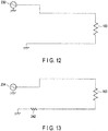
- FIG. 12 shows an equivalent circuit of the first power supply 232 that produces an output having a high-frequency first frequency in such a circuit configuration. Since the first frequency is a high frequency, a current passes through the sensing capacitor 244 in the signal detection circuit 240.
- FIG. 13 shows an equivalent circuit of the second power supply 234 that produces an output having a low-frequency second frequency. Since the second frequency is a low frequency, a current passes through the sensing resistor 242 in the signal detection circuit 240.
- a voltage detected by use of the sensing resistor 242 is a voltage related to the output from the second power supply 234.
- the frequency separation unit 252 does not have to be provided in the resistance value calculation section 250.
- the signal detection circuit 240 functions as a frequency separation unit.
- a resistance voltage having the second frequency can be acquired, so that the heater resistance Rheat can be easily obtained.
- the need for the frequency separation unit 252 can be eliminated by merely inserting the sensing capacitor 244 in parallel with the sensing resistor 242, so that the system configuration can be simplified.
- a heater resistance is calculated more accurately than in the first embodiment, in consideration of the value of the contact resistance between the power supply device connector 285 and the cable connector 195.
- FIG. 14 schematically illustrates a configuration example of the surgical system 1 according to the second embodiment.
- the resistance of the contact point between the third terminal 287 and the first terminal 197 is referred to as a first connector resistance 422
- the resistance of the contact point between the fourth terminal 288 and the second terminal 198 is referred to as a second connector resistance 424.
- the contact point between the power supply device connector 285 and the cable connector 195 changes in accordance with the number of times of use. At this time, the change at the third terminal 287 and the change at the fourth terminal 288 have the same tendency. Likewise, the change at the first terminal 197 and the change at the second terminal 198 have the same tendency.
- the cable connector 195 is provided with, in addition to the first terminal 197 and the second terminal 198, a fifth terminal 312 and a sixth terminal 314 having similar configurations to those of the first terminal 197 and the second terminal 198.
- the power supply device connector 285 is provided with, in addition to the third terminal 287 and the fourth terminal 288, a seventh terminal 322 and an eighth terminal 324 having similar configurations to those of the third terminal 287 and the fourth terminal 288.
- the fifth terminal 312 and the sixth terminal 314 are connected by a conducting wire 316.
- the controller 200 is provided with a connector resistance value detection unit 330.
- the seventh terminal 322 and the eighth terminal 324 are connected to the connector resistance value detection unit 330.
- the connector resistance value detection unit 330 detects a resistance value between the seventh terminal 322 and the eighth terminal 324.
- the connector resistance value detection unit 330 transmits the detected resistance value to the calculation unit 256.
- the contact resistance between the seventh terminal 322 and the fifth terminal 312 is referred to as a third connector resistance 426
- the contact resistance between the eighth terminal 324 and the sixth terminal 314 will be referred to as a fourth connector resistance 428.
- the connector resistance value detection unit 330 acquires a resistance value of the circuit constituted by the seventh terminal 322, the fifth terminal 312, the conducting wire 316, the sixth terminal 314 and the eighth terminal 324. That is, the connector resistance value detection unit 330 detects a resistance value including the third connector resistance 426 and the fourth connector resistance 428. The connector resistance value detection unit 330 transmits the detected resistance value to the calculation unit 256.
- the resistance values of the first connector resistance 422 and the second connector resistance 424 are substantially equal to the resistance values of the third connector resistance 426 and the fourth connector resistance 428. Therefore, the calculation unit 256 can regard the obtained resistance value as the sum of the first connector resistance 422 and the second connector resistance 424.
- the sum of the first connector resistance 422 and the second connector resistance 424 will be referred to as a connector resistance Rcon.
- the calculation unit 256 transmits the corrected heater resistance Rheat_c to the output control circuit 220.
- the output control circuit 220 calculates a heater temperature using the corrected heater resistance Rheat_c. As a result, where the heater temperature is calculated using the corrected heater resistance Rheat_c, it can be calculated more accurately than in the case where it is calculated using the heater resistance Rheat.
- the controller 200 can control the temperature of the heater 160 of the surgical instrument 100 with higher accuracy than in the first embodiment.
- the third embodiment will be described. In the description below, reference will be made to how the third embodiment differs from the first embodiment. Therefore, the same symbols will be used to denote structural elements similar or corresponding to those of the first embodiment, and a description of such structural elements will be omitted.
- the calculation unit 256 can calculate a heater resistance by further correcting the cable resistance Rcab, which is the parasitic resistance of the cable 190.
- FIG. 15 schematically shows a circuit configuration of the surgical system 1 according to the present embodiment.
- the cable resistance 432 which is the parasitic resistance of the cable 190
- the surgical instrument 100 of the present embodiment has a switch 182.
- the switch 182 is a switch for switching between a first state in which the heater resistor 163 is inserted between the first terminal 197 and the second terminal 198 and a second state in which the first terminal 197 and the second terminal 198 are short-circuited, with the heater resistor 163 bypassed.
- the switch 182 is set in the second state in the initial setting state, which is the state before the treatment is started.
- the resistance value calculation section 250 acquires a resistance value between the third terminal 287 and the fourth terminal 288. This resistance value is the sum of the connector resistance Rcon and the cable resistance Rcab.
- the switch 182 is set in the first state, and the surgical system 1 functions in the same way as in the first embodiment.
- the calculation unit 256 can calculate a corrected heater resistance Rheat_c, as below, using the sum of the connector resistance Rcon and the cable resistance Rcab obtained in the initial setting state.
- Rheat _ c Rheat ⁇ Rcon ⁇ Rcab
- the temperature of the heater 160 of the surgical instrument 100 can be controlled with higher accuracy than in the second embodiment.
- the first modification of the third embodiment will be described. In the description below, reference will be made to how the first modification differs from the third embodiment. Therefore, the same symbols will be used to denote structural elements similar or corresponding to those of the third embodiment, and a description of such structural elements will be omitted.
- the switch 182 in order to bypass the heater resistor 163, the switch 182 is used to switch between the first state and the second state.
- a variable resistor 184 is provided in parallel with the heater resistor 163 in the surgical instrument 100, as shown in FIG. 16 .
- the sum of the connector resistance Rcon and the cable resistance Rcab is measured, with the resistance value of the variable resistor 184 being sufficiently lowered in the initial setting state before the start of treatment.
- the resistance value of the variable resistor 184 is made sufficiently high.
- the temperature of the heater 160 of the surgical instrument 100 can be controlled with high accuracy.
- a voltage detection unit 186 is provided in the surgical instrument 100, as shown in FIG. 17 .
- the voltage detection unit 186 detects a potential difference between both ends of the heater resistor 163. That is, the voltage detection unit 186 can acquire a resistance value of the heater resistor 163, with the sum of the connector resistance Rcon and the cable resistance Rcab being excluded. According to this modification as well, the temperature of the heater 160 of the surgical instrument 100 can be controlled with high accuracy.
- FIG. 18 schematically illustrates a configuration example of the surgical system 1 according to the present embodiment.
- the calculation unit 256 can calculate the heater resistance 163 by further correcting the parasitic capacitance 414 of the cable 190.
- a connector resistance Rcon (a first connector resistance 422 and a second connector resistance 424) and a cable resistance Rcab (cable resistance 432) are calculated by the same means as used in the second embodiment. That is, a conducting wire 316 extending to the inside of the surgical instrument is connected to a parasitic resistance value detecting section 331, which corresponds to the connector resistance value detection unit 330 of the second embodiment. In addition to the third connector resistance 426 and the fourth connector resistance 428, the parasitic resistance value detecting section 331 also acquires a resistance value including a second cable resistance 433 corresponding to the cable resistance 432. Therefore, in addition to the connector resistance Rcon (the first connector resistance 422 and the second connector resistance 424), the parasitic resistance value detecting section 331 can also calculate a cable resistance Rcab (cable resistance 432).
- the parasitic capacitance 414 is corrected using the detection values of the first power supply 232 and the second power supply 234 and the frequency difference between the detection values.
- a corrected heater resistance Rheat_c can be
Abstract
Description
- The present invention relates to a control device for a surgical instrument, and a surgical system.
- Surgical instruments are known in which a living tissue as a treatment target portion is held by a holding section equipped with a heater and the living tissue is treated with heat generated by the heater.
- For example, Jpn. Pat. Appln. KOKAI Publication No.
2009-247893 - Also, Jpn. Pat. Appln. KOKAI Publication No.
2009-247893 - The surgical system of Jpn. Pat. Appln. KOKAI No.
2009-247893 - An object of the present invention is to provide a control device for a surgical instrument and a surgical system, which are capable of accurately controlling the temperature by accurately measuring the resistance value of a heater.
- According to one aspect of the present invention, a control device controls a surgical instrument including a heater. The control device includes a first power supply, a second power supply, a resistance value calculation section, and an output control circuit. The first power supply outputs a first current having a first frequency and supplied to the heater. The second power supply outputs a second current combined with the first current, supplied to the heater and having a second frequency different from the first frequency. The resistance value calculation section separates a signal component related to the second current from the first and second currents having passed through the heater, and calculates a heater resistance value based on the signal component. The output control circuit controls a temperature of the heater based on the heater resistance value.
- According to one aspect of the present invention, a surgical system includes the above-mentioned control device and a surgical instrument including a heater configured to generate heat when supplied with power from the control device.
- According to the present invention, it is possible to provide a control device for a surgical instrument and a surgical system, which are capable of accurately measuring the resistance value of the heater and which thereby enable accurate temperature control.
-
-
FIG. 1 is a diagram showing an example of how a surgical system according to one embodiment looks like. -
FIG. 2 is a diagram schematically showing a configuration example of a heater and its neighboring portions according to one embodiment. -
FIG. 3 is a block diagram schematically illustrating a configuration example of a surgical system according to one embodiment. -
FIG. 4 is a diagram schematically showing an electric circuit of the heater of the surgical system of the first embodiment. -
FIG. 5 is a diagram for illustrating the phase difference between an output voltage and a detection voltage. -
FIG. 6 is a flowchart illustrating an example of a system control method according to one embodiment. -
FIG. 7 is a flowchart showing an example of an output setting process according to one embodiment. -
FIG. 8 is a block diagram schematically showing a configuration example of a resistance value calculation section according to the first example. -
FIG. 9 is a block diagram schematically showing a configuration example of a resistance value calculation section according to the second example. -
FIG. 10 is a diagram schematically showing an example of an electric circuit of the heater of a surgical system according to the first modification of the first embodiment. -
FIG. 11 is a diagram schematically showing an example of an electric circuit of the heater of a surgical system according to the second modification of the first embodiment. -
FIG. 12 is a diagram schematically showing an example of an equivalent circuit of a first power supply according to the second modification of the first embodiment. -
FIG. 13 is a diagram schematically showing an example of an equivalent circuit of a second power supply according to the second modification of the first embodiment. -
FIG. 14 is a diagram schematically showing a configuration example of a surgical system according to the second embodiment. -
FIG. 15 is a diagram schematically showing a configuration example of a surgical system according to the third embodiment. -
FIG. 16 is a diagram schematically showing a configuration example of a surgical system according to the first modification of the third embodiment. -
FIG. 17 is a diagram schematically showing a configuration example of a surgical system according to the second modification of the third embodiment. -
FIG. 18 is a diagram schematically showing a configuration example of a surgical system according to the fourth embodiment. - A description will now be given of the first embodiment with reference to the accompanying drawings.
FIG. 1 schematically illustrates how thesurgical system 1 of the present embodiment looks like. Thesurgical system 1 is an apparatus used for treating a living tissue. For example, it is used for a treatment including tissue sealing, hemostasis, coagulation, tissue dissection or incision. Thesurgical system 1 performs treatment by applying energy to the living tissue. - As shown in
FIG. 1 , thesurgical system 1 includes asurgical instrument 100 for performing a treatment and acontroller 200 for supplying power to thesurgical instrument 100. In thesurgical system 1, thesurgical instrument 100 and thecontroller 200 operate in cooperation. - The
surgical instrument 100 is, for example, a surgical instrument for surgical treatments of penetrating an abdominal wall. Thesurgical instrument 100 includes ahandle 120, ashaft 116 attached to thehandle 120, and aholding section 110 that is an end effector provided at the distal end of theshaft 116. - The
holding section 110 has afirst holding member 112 and asecond holding member 114. Thefirst holding member 112 is displaced with respect to thesecond holding member 114, so that theholding section 110 opens and closes. Theholding section 110 is configured to grasp a living tissue, which is a treatment target, between thefirst holding member 112 and thesecond holding member 114. Theholding section 110 is a treatment part that holds the living tissue as the treatment target, and performs treatment such as coagulation or incision of the living tissue. Thehandle 120 includes a plurality ofoperation knobs 122 for operating the holdingsection 110. - In the descriptions set forth below, a portion of the
surgical instrument 100 that is closer to theholding section 110 will be referred to as a distal side, and a portion that is closer to thehandle 120 will be referred to as a proximal side. - It should be noted that the shape of the
surgical instrument 100 shown in the drawings is nothing but an example, and other shapes may be used as long as they have similar functions. For example, the length and shape of the shaft can be changed as appropriate. The technique according to the present embodiment is not limited to a treatment device for rigid endoscopic surgery, such as that shown inFIG. 1 , but is also applicable to a treatment device used for endoscopic surgery using a flexible endoscope. - The
surgical instrument 100 is connected to thecontroller 200 through acable 190. Thecable 190 and thecontroller 200 are connected by acable connector 195, and they are detachable from each other. That is, thesurgical system 1 is configured such that asurgical instrument 100 to be used for each treatment can be properly chosen. - A
foot switch 290 is connected to thecontroller 200. Thefoot switch 290 operated by foot may be replaced with a manually operable hand switch or any other type of switch. The supply of energy to thesurgical instrument 100 from thecontroller 200 is switched on or off by operating the pedal of thefoot switch 290 by an operator. - A heater for converting power into heat is provided near that portion of at least one of the first and second holding
members - The
heater 160 and its neighboring structure will be described with reference toFIG. 2 . Aheat transfer member 166 made of, for example, copper is provided on those surfaces of the first and second holdingmembers heater 160 has a structure in which aheat generating member 168 is provided on asubstrate 167. Thesubstrate 167 is, for example, a polyimide substrate. Thesubstrate 167 is slightly smaller than theheat transfer member 166 and has the same shape as theheat transfer member 166. Theheat generating member 168 is, for example, a resistive pattern of stainless steel (SUS) formed on thesubstrate 167. Both ends of theheat generating member 168 are provided on the proximal end side, and theheat generating member 168 has a substantially U-shaped pattern. This pattern is formed to have a small line width in order to increase electrical resistance and have a corrugated shape in order to cover a wide range of the substrate. One end of aconductive wire 169 is connected to each of the ends of theheat generating member 168. - The other end of each
conductive wire 169 is electrically connected to thepower supply device 230 of thecontroller 200 to be described later. When power is supplied to theheat generating member 168, theheat generating member 168 converts the power into heat and thus generates heat. The heat generated by theheat generating member 168 is transmitted to theheat transfer member 166 via thesubstrate 167. This heat is transmitted to the living tissue that is in contact with theheat transfer member 166, and the living tissue is subjected to heat treatment. - In the
surgical system 1 according to the present embodiment, the temperature of theheat transfer member 166 is controlled by thecontroller 200. It should be noted here that the temperature of theheat transfer member 166 is controlled by feedback control that is performed with the temperature of theheater 160 acquired. Since a known predetermined relationship exists between the resistance value of theheat generating member 168 and the temperature thereof, the temperature of theheater 160 is calculated based on the resistance value of theheat generating member 168. That is, thecontroller 200 acquires the resistance value of theheat generating member 168 and calculates the temperature of theheat generating member 168 based on this resistance value and the known predetermined relationship. -
FIG. 3 schematically illustrates a configuration example of thesurgical system 1. Thesurgical instrument 100 is provided with theheater 160, as described above. Theheater 160 has aheater resistor 163 electrically corresponding to theheat generating member 168. One end of theheater resistor 163 is connected to thefirst terminal 197 of thecable connector 195 via thecable 190. The other end of theheater resistor 163 is connected to thesecond terminal 198 of thecable connector 195 via thecable 190. - The
controller 200 comprises acontrol circuit 212, astorage device 214, adisplay device 216, aninput device 218, anoutput control circuit 220, apower supply device 230, a resistancevalue calculation section 250, and a powersupply device connector 285. - The power
supply device connector 285 is a terminal to which thecable connector 195 is connected. The powersupply device connector 285 has athird terminal 287 connected to thefirst terminal 197 of thecable connector 195 and afourth terminal 288 connected to thesecond terminal 198 of thecable connector 195. - The
power supply device 230 includes two power supplies, namely, aheater power supply 231 and a temperaturemeasurement power supply 233. Theheater power supply 231 includes afirst power supply 232 which is, for example, an AC power supply. On the other hand, the temperaturemeasurement power supply 233 includes asecond power supply 234 which is, for example, an AC power supply. Theheater power supply 231 is a power supply for outputting power for heating theheater 160. On the other hand, the temperaturemeasurement power supply 233 is a power supply that outputs power for the purpose of measuring the resistance value of theheater 160 in order to acquire the temperature of theheater 160. - The output of the
heater power supply 231 varies in accordance with the amount of heat to be supplied, that is, in accordance with the difference between the current temperature of theheater 160 and the target temperature. The output of the temperaturemeasurement power supply 233 is a predetermined constant voltage, current or power. In general, the first output that is the output of theheater power supply 231 is higher than the second output that is the output of the temperaturemeasurement power supply 233. For example, the current value of the second current related to the second output is smaller than the current value of the first current related to the first output. In the present embodiment, the first frequency that is the output frequency of thefirst power supply 232 of theheater power supply 231 is higher than the second frequency that is the output frequency of thesecond power supply 234 of the temperaturemeasurement power supply 233. Since, as will be described later, the first frequency and the second frequency are separated, the first frequency is preferably 10 times or more the second frequency in order to facilitate separation. For example, the first frequency is 100 kHz, and the second frequency is 10 kHz. - One end of the
first power supply 232 is grounded, and the other output end is connected to thethird terminal 287 via afirst capacitor 237. One end of thesecond power supply 234 is grounded, and the other output end is connected to thethird terminal 287 via anoutput detection circuit 236 and afirst inductor 238. Theoutput detection circuit 236 is a circuit for detecting the output voltage of thesecond power supply 234. Theoutput detection circuit 236 transmits the detected output voltage to thecalculation unit 256 of the resistancevalue calculation section 250 to be described later. - In general, a capacitor passes high-frequency signals and an inductor passes low-frequency signals. Therefore, an output signal of the
heater power supply 231 having the first frequency, which is a comparatively high frequency, passes through thefirst capacitor 237. An output signal of the temperaturemeasurement power supply 233 having the second frequency, which is a comparatively low frequency, passes through thefirst inductor 238. In this way, thefirst capacitor 237 and thefirst inductor 238 serve to suppress mutual interference between the output of theheater power supply 231 and the output of the temperaturemeasurement power supply 233. Thus, the first current output from thefirst power supply 232 and the second current output from thesecond power supply 234 are combined and flow through the same path. - The resistance
value calculation section 250 includes asignal detection circuit 240, afrequency separation unit 252 and acalculation unit 256. Thesignal detection circuit 240 detects a signal for calculating the resistance value of theheater resistor 163 of thesurgical instrument 100. More specifically, thesignal detection circuit 240 includes asensing resistor 242 connected in series with theheater resistor 163. One end of thesensing resistor 242 is connected to theheater resistor 163, and the other end thereof is grounded. Thesignal detection circuit 240 detects a potential difference across thesensing resistor 242, that is, a voltage applied across thesensing resistor 242, as a detection voltage. - The
frequency separation unit 252 extracts a component having a second frequency from the detection voltage detected by thesignal detection circuit 240. Thecalculation unit 256 calculates a resistance value of theheater resistor 163, based on the detection voltage having the second frequency extracted by thefrequency separation unit 252 and the output voltage detected by theoutput detection circuit 236. - There are several configurations of the
frequency separation unit 252, as will be described in detail later. Thefrequency separation unit 252 may be, for example, a filter circuit. That is, thefrequency separation unit 252 may be constituted by a low-pass filter that passes only signals of the comparatively low second frequency of the temperaturemeasurement power supply 233. Alternatively, thefrequency separation unit 252 may be constituted by an arithmetic circuit. This type offrequency separation unit 252 performs such arithmetic operations as fast Fourier transform (FFT) or wavelet transform. By such arithmetic operations, thefrequency separation unit 252 may extract only signals of comparatively a low second frequency derived from the temperaturemeasurement power supply 233. - The
output control circuit 220 controls the operations of theheater power supply 231 and the temperaturemeasurement power supply 233, based on the resistance value of theheater resistor 163 calculated by thecalculation unit 256 and the command acquired from thecontrol circuit 212. This control includes temperature control of theheater 160 so that appropriate treatments can be taken. - The
control circuit 212 controls the operation of each portion of thecontroller 200. Thedisplay device 216 includes, for example, a liquid crystal display panel, an LED lamp, and the like. Under the control of thecontrol circuit 212, thedisplay device 216 presents various information on thesurgical system 1 to the user. Theinput device 218 includes general input devices, such as a keyboard, a touch panel and a switch. Theinput device 218 acquires an input from the user and transmits it to thecontrol circuit 212. Further, an input to thefoot switch 290 is transmitted to thecontrol circuit 212. Thecontrol circuit 212 transmits, to theoutput control circuit 220, various kinds of information, for example, information on an output setting value of thesurgical instrument 100 and information indicating that the foot switch is on or off. Thestorage device 214 stores programs related to the control of thecontrol circuit 212, various necessary parameters, and the like. - The
control circuit 212, theoutput control circuit 220 and thecalculation unit 256 include an integrated circuit, such as a Central Processing Unit (CPU), an Application Specific Integrated Circuit (ASIC), or a Field Programmable Gate Array (FPGA) . Thecontrol circuit 212, theoutput control circuit 220, and thecalculation unit 256 may each be constituted by one integrated circuit or the like, or a combination of a plurality of integrated circuits. In addition, two or more of thecontrol circuit 212, theoutput control circuit 220, thecalculation unit 256 and the like may be constituted by one integrated circuit. The operations of these integrated circuits are performed in accordance with a program recorded in thestorage device 214 or in a recording area of an integrated circuit. - In the
surgical system 1 according to the present embodiment, a parasitic component attributable mainly to thecable 190 is present.FIG. 4 shows a circuit diagram including the parasitic component of thesurgical system 1 of the present embodiment. As shown inFIG. 4 , asecond inductor 412 is present as the parasitic component between thefirst terminal 197 and theheater resistor 163. Therefore, the phases of the output voltages of the first andsecond power supplies signal detection circuit 240. In the present embodiment, this phase shift is adjusted. -
FIG. 5 shows an example of the waveforms of an output voltage detected by theoutput detection circuit 236 and a detection voltage detected by thesignal detection circuit 240 . In this Figure, x indicates a phase shift and y indicates one cycle. A phase difference α is calculated as below, using x and y,
- With respect to the detection voltage Vdet detected by the
signal detection circuit 240, a correction detection voltage Vdet_c, which is obtained by correcting the phase difference α, is expressed by:
- In this way, unnecessary phase information included in the signal detected by the
signal detection circuit 240 is removed. - Since the
heater resistor 163 and thesensing resistor 242 whose resistance value is known are connected in series, a correction detection voltage Vdet c is expressed by
heater resistor 163, Rdet is a sensing resistor, and Vout is an output voltage. Therefore, the heater resistance Rheat is expressed by
- A description will now be given of an operation performed by the
surgical system 1 of the present embodiment. First, the operator operates theinput device 218 of thecontroller 200 to enter output conditions of thesurgical system 1, including a target temperature and a heating time of the treatment. The output conditions may be entered by individually setting a value for each parameter or by selecting a set of setting values suitable to the treatment. - The
handle 120 and theshaft 116 of thesurgical instrument 100 are inserted, for example, into an abdominal cavity through an abdominal wall. The operator operates the operation knobs 122 to open or close the holdingsection 110, and holds a living tissue as a treatment target with the first holdingmember 112 and the second holdingmember 114. At this time, the living tissue to be treated comes into contact with theheat transfer members 166 provided on the first and second holdingmembers - The operator operates the
foot switch 290 after holding the living tissue to be treated with the holdingsection 110. When thefoot switch 290 is turned on, power is supplied from thecontroller 200 to theheater 160 via a conductive wire passing through thecable 190. The target temperature is, for example, 200°C. At this time, current flows through theheat generating members 168. Theheat generating members 168 generate heat because of this current. The heat generated by theheat generating members 168 is transmitted to theheat transfer members 166 via thesubstrates 167. As a result, the temperature of theheat transfer members 166 increases. - By the heat transmitted to the
heat transfer members 166, the living tissue that is in contact with theheat transfer members 166 is cauterized and coagulated. When the living tissue is coagulated by heating, the supply of power to theheater 160 is stopped. In this manner, the treatment of the living tissue is completed - How the
controller 200 performs a system control process in the above operation will be described, referring to the flowchart shown inFIG. 6 . - In step S101, the
controller 200 performs condition setting. That is, thecontrol circuit 212 causes thedisplay device 216 to display for presenting the user a message prompting the user to enter conditions of the treatment, such as a target temperature and a heating time. Alternatively, thecontrol circuit 212 causes thedisplay device 216 to display currently-set conditions of the procedure, such as a target temperature and a heating time . Thecontrol circuit 212 acquires user's inputs from theinput device 218. Thecontrol circuit 212 sets conditions of the treatment, such as a target temperature and a heating time, in accordance with the user's inputs obtained from theinput device 218. Thecontrol circuit 212 transmits the set conditions to theoutput control circuit 220. - In step S102, the
control circuit 212 determines whether or not thefoot switch 290 is on. If thefoot switch 290 is not on, the process proceeds to step S103. In step S103, it is determined whether or not the power supply is turned off . Unless the power supply is turned off, the process returns to step S102 . That is, while thefoot switch 290 is off and the power supply is on, the process repeats steps S102 and S103 and stands by. When the power supply is turned off, the system control process ends. In step S102, if thefoot switch 290 is on, the process proceeds to step S104. - In step S104, the
controller 200 turns on the output of theheater power supply 231 and the temperaturemeasurement power supply 233. That is, thecontrol circuit 212 informs theoutput control circuit 220 that thefoot switch 290 is turned on. At this time, theoutput control circuit 220 controls the operations of theheater power supply 231 and the temperaturemeasurement power supply 233 such that these power supplies output power. The output of theheater power supply 231 is an AC voltage having a first frequency, and the voltage value is a predetermined initial value. The output of the temperaturemeasurement power supply 233 is an AC voltage having a second frequency, and the voltage value is a predetermined measurement voltage value. - In step S105, the
controller 200 performs an output setting process. The output setting process will be described with reference to the flowchart shown inFIG. 7 . - In step S201, the
calculation unit 256 of the resistancevalue calculation section 250 acquires an output voltage Vout of the temperaturemeasurement power supply 233 from theoutput detection circuit 236. - In step S202, the resistance
value calculation section 250 acquires a detection signal related to the detection voltage Vdet from thesignal detection circuit 240. - In step S203, the
frequency separation unit 252 of the resistancevalue calculation section 250 acquires a detection voltage Vdet, which is a signal component made to have a second frequency by frequency separation, from the detection signal of thesignal detection circuit 240. The detection voltage Vdet is transmitted to thecalculation unit 256. - In step S204, the
calculation unit 256 calculates a heater resistance Rheat according to the above calculation method, based on the output voltage Vout and the detection voltage Vdet. Thecalculation unit 256 transmits the calculated heater resistance Rheat to theoutput control circuit 220. - In step S205, the
output control circuit 220 calculates a heater temperature indicative of the temperature of theheater 160, based on the heater resistance Rheat. The heater temperature is obtained, for example, based on a table stored in thestorage device 214 and showing the relationship between the heater resistance Rheat and the heater temperature. The heater temperature may be calculated by thecalculation unit 256. - In step S206, the
output control circuit 220 performs output setting for theheater power supply 231, using the heater temperature. For example, theoutput control circuit 220 increases or decreases the output voltage of theheater power supply 231, based on the difference between the target temperature set in step S101 and the heater temperature. - In the above manner, the output setting process is completed. The process proceeds to step S106 of the system control process described with reference to
FIG. 6 . - In step S106, the
control circuit 212 determines whether or not to turn off the output. For example, if thefoot switch 290 is turned off, it is determined that the output should be turned off. Alternatively, if the time elapsed from the time when the output is turned on exceeds a predetermined period, it is determined that the output should be turned off. Unless it is determined that the output should be turned off, the process returns to step S105. That is, the output is continued, and the output of theheater power supply 231 is adjusted again. On the other hand, if it is determined that the output should be turned off, the process proceeds to step S107. - In step S107, the
controller 200 turns off the output of theheater power supply 231 and the temperaturemeasurement power supply 233. - In step S108, it is determined whether or not change of the condition setting made in S101 is requested. If the change of the condition setting is requested, the process returns to step S101. In other words, condition setting is performed again, and the output is started when the
foot switch 290 is turned on. Unless the change of the condition setting is requested, the process returns to step S102. That is, when thefoot switch 290 is turned on, the output performed again. - The configuration of the resistance
value calculation section 250 will be described. A signal having the second frequency derived from the signal output from the temperaturemeasurement power supply 233 can be extracted from the detection signal acquired by thesignal detection circuit 240 in a number of methods. Examples of the methods will be described. - The first method is a method using a filter circuit.
FIG. 8 schematically shows a configuration example of the resistancevalue calculation section 250 that employs the filter circuit. In this example, thefrequency separation unit 252 includes afilter circuit 253. Thecalculation unit 256 includes anarithmetic circuit 257. In the present embodiment, thefilter circuit 253 includes a low-pass filter because the second frequency is lower than the first frequency. Of the signals detected by thesignal detection circuit 240, a signal passing through thefilter circuit 253 is input to thearithmetic circuit 257. That is, of the signals detected by thesignal detection circuit 240, a signal derived from the signal output from the temperaturemeasurement power supply 233 and having the second frequency is input to thearithmetic circuit 257. In this way, thearithmetic circuit 257 acquires a detection voltage Vdet. Thearithmetic circuit 257 calculates a heater resistance Rheat using the detection voltage Vdet. The calculated heater resistance Rheat is transmitted to theoutput control circuit 220. - The second method is a method in which frequency separation is performed by an arithmetic operation.
FIG. 9 schematically shows a configuration example of the resistancevalue calculation section 250 that performs frequency separation by an arithmetic operation. The resistancevalue calculation section 250 according to the second method includes anarithmetic circuit 251. In thearithmetic circuit 251, an arithmetic operation for frequency separation, such as fast Fourier transform or wavelet transform, is performed by afrequency separation unit 252. A signal corresponding to the second frequency included in the frequencies obtained by the operation is extracted. In thearithmetic circuit 251, a heater resistance Rheat is calculated by thecalculation unit 256. The calculated heater resistance Rheat is transmitted to theoutput control circuit 220. - According to the present embodiment, a heater resistance Rheat can be accurately obtained. To obtain the heater resistance Rheat, it is also possible to use the output of the
heater power supply 231 for causing theheater 160 to generate heat. However, the output of theheater power supply 231 changes in accordance with the target temperature and the current temperature of theheater 160. In order to obtain the heater resistance Rheat based on the output that changes in this manner, for example, thesignal detection circuit 240 is required to accurately detect a wide range of voltage. On the other hand, where the output of the temperaturemeasurement power supply 233, which is constant at all times, is used, as in the present embodiment, thesignal detection circuit 240 can easily detect a voltage with high accuracy. In the present embodiment, the output current of theheater power supply 231 for heating theheater 160 and the output current of the temperaturemeasurement power supply 233 are combined and pass through the same path, but the frequencies of the two output signals are different. Therefore, the signals are separated from each other owing to this frequency difference. - The first modification of the first embodiment will be described. In the description below, reference will be made to how the first modification differs from the first embodiment. Therefore, the same symbols will be used to denote structural elements similar or corresponding to those of the first embodiment, and a description of such structural elements will be omitted. In the above-mentioned embodiment, the first frequency, which is the output frequency of the
first power supply 232 of theheater power supply 231, is higher than the second frequency, which is the output frequency of thesecond power supply 234 of the temperaturemeasurement power supply 233. Conversely, the first frequency may be lower than the second frequency, as in the present modification. In this case, as shown inFIG. 10 , athird inductor 2391 is connected to the output terminal of thefirst power supply 232, and athird capacitor 2392 is connected to the output terminal of thesecond power supply 234. In this case, where thefrequency separation unit 252 is configured as afilter circuit 253, thefilter circuit 253 is a high-pass filter. Where thefrequency separation unit 252 is realized by using such an arithmetic operation as fast Fourier transform or wavelet transform performed by thearithmetic circuit 251, a second frequency higher than the first frequency is extracted by the operation. - Furthermore, the first frequency or the second frequency may be zero, that is, the output of the
first power supply 232 or thesecond power supply 234 may be a direct current. In this case, the frequency of the direct-current output of either thefirst power supply 232 or thesecond power supply 234 is lower than the frequency of the other output. - According to this modification as well, the same advantages as those of the first embodiment can be obtained.
- The second modification of the first embodiment will be described. In the description below, reference will be made to how the second modification differs from the first embodiment. Therefore, the same symbols will be used to denote structural elements similar or corresponding to those of the first embodiment, and a description of such structural elements will be omitted. In the present modification, as shown in
FIG. 11 , asensing capacitor 244 is provided in parallel with thesensing resistor 242 in thesignal detection circuit 240.FIG. 12 shows an equivalent circuit of thefirst power supply 232 that produces an output having a high-frequency first frequency in such a circuit configuration. Since the first frequency is a high frequency, a current passes through thesensing capacitor 244 in thesignal detection circuit 240. On the other hand,FIG. 13 shows an equivalent circuit of thesecond power supply 234 that produces an output having a low-frequency second frequency. Since the second frequency is a low frequency, a current passes through thesensing resistor 242 in thesignal detection circuit 240. - In the
signal detection circuit 240 of the present modification, a voltage detected by use of thesensing resistor 242 is a voltage related to the output from thesecond power supply 234. In the case of this modification, therefore, thefrequency separation unit 252 does not have to be provided in the resistancevalue calculation section 250. In this modification, thesignal detection circuit 240 functions as a frequency separation unit. - According to this modification as well, a resistance voltage having the second frequency can be acquired, so that the heater resistance Rheat can be easily obtained. In particular, in the present modification, the need for the
frequency separation unit 252 can be eliminated by merely inserting thesensing capacitor 244 in parallel with thesensing resistor 242, so that the system configuration can be simplified. - It is to be noted that the present modification can also be put into practice where the output of the
second power supply 234 is a direct current. - The second embodiment will be described. In the description below, reference will be made to how the second embodiment differs from the first embodiment. Therefore, the same symbols will be used to denote structural elements similar or corresponding to those of the first embodiment, and a description of such structural elements will be omitted. In the present embodiment, a heater resistance is calculated more accurately than in the first embodiment, in consideration of the value of the contact resistance between the power
supply device connector 285 and thecable connector 195. -
FIG. 14 schematically illustrates a configuration example of thesurgical system 1 according to the second embodiment. The resistance of the contact point between thethird terminal 287 and thefirst terminal 197 is referred to as afirst connector resistance 422, and the resistance of the contact point between thefourth terminal 288 and thesecond terminal 198 is referred to as asecond connector resistance 424. - The contact point between the power
supply device connector 285 and thecable connector 195 changes in accordance with the number of times of use. At this time, the change at thethird terminal 287 and the change at thefourth terminal 288 have the same tendency. Likewise, the change at thefirst terminal 197 and the change at thesecond terminal 198 have the same tendency. - In the present embodiment, therefore, the
cable connector 195 is provided with, in addition to thefirst terminal 197 and thesecond terminal 198, afifth terminal 312 and asixth terminal 314 having similar configurations to those of thefirst terminal 197 and thesecond terminal 198. Similarly, the powersupply device connector 285 is provided with, in addition to thethird terminal 287 and thefourth terminal 288, aseventh terminal 322 and aneighth terminal 324 having similar configurations to those of thethird terminal 287 and thefourth terminal 288. Thefifth terminal 312 and thesixth terminal 314 are connected by aconducting wire 316. When thecable connector 195 is connected to the powersupply device connector 285, thefifth terminal 312 and theseventh terminal 322 are connected to each other, and thesixth terminal 314 and theeighth terminal 324 are connected to each other. - The
controller 200 is provided with a connector resistancevalue detection unit 330. Theseventh terminal 322 and theeighth terminal 324 are connected to the connector resistancevalue detection unit 330. The connector resistancevalue detection unit 330 detects a resistance value between theseventh terminal 322 and theeighth terminal 324. The connector resistancevalue detection unit 330 transmits the detected resistance value to thecalculation unit 256. - Where the
cable connector 195 is connected to the powersupply device connector 285, the contact resistance between theseventh terminal 322 and thefifth terminal 312 is referred to as athird connector resistance 426, and the contact resistance between theeighth terminal 324 and thesixth terminal 314 will be referred to as afourth connector resistance 428. Where thecable connector 195 is connected to the powersupply device connector 285, the connector resistancevalue detection unit 330 acquires a resistance value of the circuit constituted by theseventh terminal 322, thefifth terminal 312, theconducting wire 316, thesixth terminal 314 and theeighth terminal 324. That is, the connector resistancevalue detection unit 330 detects a resistance value including thethird connector resistance 426 and thefourth connector resistance 428. The connector resistancevalue detection unit 330 transmits the detected resistance value to thecalculation unit 256. - The resistance values of the
first connector resistance 422 and thesecond connector resistance 424 are substantially equal to the resistance values of thethird connector resistance 426 and thefourth connector resistance 428. Therefore, thecalculation unit 256 can regard the obtained resistance value as the sum of thefirst connector resistance 422 and thesecond connector resistance 424. The sum of thefirst connector resistance 422 and thesecond connector resistance 424 will be referred to as a connector resistance Rcon. - The
calculation unit 256 can calculate a corrected heater resistance Rheat_c corrected with the value of the connector resistance Rcon, by the following:
- The
calculation unit 256 transmits the corrected heater resistance Rheat_c to theoutput control circuit 220. Theoutput control circuit 220 calculates a heater temperature using the corrected heater resistance Rheat_c. As a result, where the heater temperature is calculated using the corrected heater resistance Rheat_c, it can be calculated more accurately than in the case where it is calculated using the heater resistance Rheat. - According to the present embodiment, the
controller 200 can control the temperature of theheater 160 of thesurgical instrument 100 with higher accuracy than in the first embodiment. - The third embodiment will be described. In the description below, reference will be made to how the third embodiment differs from the first embodiment. Therefore, the same symbols will be used to denote structural elements similar or corresponding to those of the first embodiment, and a description of such structural elements will be omitted. In the second embodiment described above, as a parasitic resistance, only the connector resistance Rcon is taken into consideration and corrected. In the present embodiment, the
calculation unit 256 can calculate a heater resistance by further correcting the cable resistance Rcab, which is the parasitic resistance of thecable 190. -
FIG. 15 schematically shows a circuit configuration of thesurgical system 1 according to the present embodiment. In the present embodiment, thecable resistance 432, which is the parasitic resistance of thecable 190, is taken into consideration. Thesurgical instrument 100 of the present embodiment has aswitch 182. Theswitch 182 is a switch for switching between a first state in which theheater resistor 163 is inserted between thefirst terminal 197 and thesecond terminal 198 and a second state in which thefirst terminal 197 and thesecond terminal 198 are short-circuited, with theheater resistor 163 bypassed. - In the present embodiment, the
switch 182 is set in the second state in the initial setting state, which is the state before the treatment is started. In this state, the resistancevalue calculation section 250 acquires a resistance value between thethird terminal 287 and thefourth terminal 288. This resistance value is the sum of the connector resistance Rcon and the cable resistance Rcab. - At the time of treatment, the
switch 182 is set in the first state, and thesurgical system 1 functions in the same way as in the first embodiment. In the present embodiment, thecalculation unit 256 can calculate a corrected heater resistance Rheat_c, as below, using the sum of the connector resistance Rcon and the cable resistance Rcab obtained in the initial setting state.
- According to the present embodiment, the temperature of the
heater 160 of thesurgical instrument 100 can be controlled with higher accuracy than in the second embodiment. - The first modification of the third embodiment will be described. In the description below, reference will be made to how the first modification differs from the third embodiment. Therefore, the same symbols will be used to denote structural elements similar or corresponding to those of the third embodiment, and a description of such structural elements will be omitted. In the third embodiment, in order to bypass the
heater resistor 163, theswitch 182 is used to switch between the first state and the second state. In this modification, avariable resistor 184 is provided in parallel with theheater resistor 163 in thesurgical instrument 100, as shown inFIG. 16 . - In the present embodiment as well, the sum of the connector resistance Rcon and the cable resistance Rcab is measured, with the resistance value of the
variable resistor 184 being sufficiently lowered in the initial setting state before the start of treatment. On the other hand, at the time of treatment, the resistance value of thevariable resistor 184 is made sufficiently high. The other points are the same as those of the third embodiment. According to this modification as well, the temperature of theheater 160 of thesurgical instrument 100 can be controlled with high accuracy. - The second modification of the third embodiment will be described. In the description below, reference will be made to how the second modification differs from the third embodiment. Therefore, the same symbols will be used to denote structural elements similar or corresponding to those of the third embodiment, and a description of such structural elements will be omitted. In this modification, a
voltage detection unit 186 is provided in thesurgical instrument 100, as shown inFIG. 17 . Thevoltage detection unit 186 detects a potential difference between both ends of theheater resistor 163. That is, thevoltage detection unit 186 can acquire a resistance value of theheater resistor 163, with the sum of the connector resistance Rcon and the cable resistance Rcab being excluded. According to this modification as well, the temperature of theheater 160 of thesurgical instrument 100 can be controlled with high accuracy. - The fourth embodiment will be described. In the description below, reference will be made to how the fourth embodiment differs from the second embodiment. Therefore, the same symbols will be used to denote structural elements similar or corresponding to those of the third embodiment, and a description of such structural elements will be omitted.
FIG. 18 schematically illustrates a configuration example of thesurgical system 1 according to the present embodiment. In the third embodiment described above, only the connector resistance Rcon of the parasitic resistance (thefirst connector resistance 422 and the second connector resistance 424) and the cable resistance Rcab (the cable resistance 432) are taken into consideration and corrected. In the present embodiment, thecalculation unit 256 can calculate theheater resistance 163 by further correcting theparasitic capacitance 414 of thecable 190. - As shown in
FIG. 18 , a connector resistance Rcon (afirst connector resistance 422 and a second connector resistance 424) and a cable resistance Rcab (cable resistance 432) are calculated by the same means as used in the second embodiment. That is, aconducting wire 316 extending to the inside of the surgical instrument is connected to a parasitic resistancevalue detecting section 331, which corresponds to the connector resistancevalue detection unit 330 of the second embodiment. In addition to thethird connector resistance 426 and thefourth connector resistance 428, the parasitic resistancevalue detecting section 331 also acquires a resistance value including asecond cable resistance 433 corresponding to thecable resistance 432. Therefore, in addition to the connector resistance Rcon (thefirst connector resistance 422 and the second connector resistance 424), the parasitic resistancevalue detecting section 331 can also calculate a cable resistance Rcab (cable resistance 432). - Furthermore, in the present embodiment, the
parasitic capacitance 414 is corrected using the detection values of thefirst power supply 232 and thesecond power supply 234 and the frequency difference between the detection values. A corrected heater resistance Rheat_c is expressed bymathematical formula 1 below,
heater 160 can be detected more accurately.
Claims (12)
- A control device for a surgical instrument including a heater configured to generate heat in response to power supplied thereto, the control device comprising:a first power supply configured to output a first current having a first frequency and supplied to the heater for causing the heater to generate heat;a second power supply configured to output a second current combined with the first current, supplied to the heater and having a second frequency different from the first frequency;a resistance value calculation section configured to separate a signal component related to the second current from the first and second currents having passed through the heater, and to calculate a heater resistance value, which is a resistance value of the heater, based on the signal component; andan output control circuit configured to control a temperature of the heater based on the heater resistance value.
- The control device according to claim 1, wherein the first current and the second current are both alternating currents.
- The control device according to claim 2, wherein the resistance value calculation section calculates the heater resistance value, with phase information included in the signal component being removed.
- The control device according to claim 3, wherein the resistance value calculation section includes a signal detection circuit including a sensing resistor provided in series with the heater, and
the resistance value calculation section calculates the heater resistance value based on a potential difference between both ends of the sensing resistor, an output voltage of the second power supply, and a resistance value of the sensing resistor. - The control device according to claim 4, wherein the first frequency is higher than the second frequency, and
the signal detection circuit further includes a sensing capacitor provided in parallel with the sensing resistor. - The control device according to claim 1, wherein one of the first current and the second current is an alternating current, and a remaining one thereof is a direct current.
- The control device according to claim 6, wherein the second current is a direct current,
the resistance value calculation section includes a signal detection circuit including a sensing resistor provided in series with the heater and a sensing capacitor provided in parallel with the sensing resistor, and
the resistance value calculation section calculates the heater resistance value based on a potential difference between both ends of the sensing resistor, an output voltage of the second power supply, and a resistance value of the sensing resistor. - The control device according to claim 1, wherein the resistance value calculation section includes a filter circuit, and
the resistance value calculation section separates the signal component, using the filter circuit. - The control device according to claim 1, wherein the resistance value calculation section separates the signal component by fast Fourier transform or wavelet transform.
- The control device according to claim 1, wherein a current value of the second current is smaller than a current value of the first current.
- The control device according to claim 1, wherein the first frequency is 10 times or more the second frequency.
- A surgical system comprising:a control device as defined in claim 1; anda surgical instrument including a heater configured to generate heat in response to power supplied from the control device.
Applications Claiming Priority (1)
| Application Number | Priority Date | Filing Date | Title |
|---|---|---|---|
| PCT/JP2015/085674 WO2017109832A1 (en) | 2015-12-21 | 2015-12-21 | Device for controlling surgical instrument, and surgical system |
Publications (2)
| Publication Number | Publication Date |
|---|---|
| EP3395276A1 true EP3395276A1 (en) | 2018-10-31 |
| EP3395276A4 EP3395276A4 (en) | 2019-08-21 |
Family
ID=59090898
Family Applications (1)
| Application Number | Title | Priority Date | Filing Date |
|---|---|---|---|
| EP15911270.5A Withdrawn EP3395276A4 (en) | 2015-12-21 | 2015-12-21 | Device for controlling surgical instrument, and surgical system |
Country Status (5)
| Country | Link |
|---|---|
| US (1) | US11051879B2 (en) |
| EP (1) | EP3395276A4 (en) |
| JP (1) | JPWO2017109832A1 (en) |
| CN (1) | CN108472068A (en) |
| WO (1) | WO2017109832A1 (en) |
Families Citing this family (2)
| Publication number | Priority date | Publication date | Assignee | Title |
|---|---|---|---|---|
| WO2018167877A1 (en) * | 2017-03-15 | 2018-09-20 | オリンパス株式会社 | Energy source device |
| US20220008670A1 (en) * | 2018-08-10 | 2022-01-13 | Fisher & Paykel Healthcare Limited | Heater plate assembly in humidifier systems for medical use |
Family Cites Families (7)
| Publication number | Priority date | Publication date | Assignee | Title |
|---|---|---|---|---|
| JPH08213151A (en) * | 1995-02-08 | 1996-08-20 | Kawasaki Steel Corp | Deterioration judgement method for heater wire and electrical equipment using the wire |
| US20060030914A1 (en) * | 2002-01-18 | 2006-02-09 | Apsara Medical Corporation | System, method and apparatus for evaluating tissue temperature |
| JP4734012B2 (en) * | 2005-04-05 | 2011-07-27 | オリンパスメディカルシステムズ株式会社 | Fever treatment device |
| US7846158B2 (en) * | 2006-05-05 | 2010-12-07 | Covidien Ag | Apparatus and method for electrode thermosurgery |
| US9642669B2 (en) | 2008-04-01 | 2017-05-09 | Olympus Corporation | Treatment system, and treatment method for living tissue using energy |
| JP5814685B2 (en) * | 2011-08-05 | 2015-11-17 | オリンパス株式会社 | Therapeutic treatment device |
| EP2856935A1 (en) * | 2013-09-26 | 2015-04-08 | Biotronik AG | Medical device for evaluating a temperature signal |
-
2015
- 2015-12-21 WO PCT/JP2015/085674 patent/WO2017109832A1/en active Application Filing
- 2015-12-21 EP EP15911270.5A patent/EP3395276A4/en not_active Withdrawn
- 2015-12-21 JP JP2017557534A patent/JPWO2017109832A1/en active Pending
- 2015-12-21 CN CN201580085398.6A patent/CN108472068A/en active Pending
-
2018
- 2018-06-21 US US16/014,832 patent/US11051879B2/en active Active
Also Published As
| Publication number | Publication date |
|---|---|
| CN108472068A (en) | 2018-08-31 |
| US20180296265A1 (en) | 2018-10-18 |
| JPWO2017109832A1 (en) | 2018-10-11 |
| US11051879B2 (en) | 2021-07-06 |
| EP3395276A4 (en) | 2019-08-21 |
| WO2017109832A1 (en) | 2017-06-29 |
Similar Documents
| Publication | Publication Date | Title |
|---|---|---|
| CN111479497B (en) | Method for assessing contact between an electrode and tissue using complex impedance measurements | |
| JP6410505B2 (en) | System and method for measuring tissue impedance through an electrosurgical cable | |
| JP6415881B2 (en) | System and method for generating electrosurgical energy using a multi-stage power converter | |
| JP6377910B2 (en) | System and method for narrowband real impedance control in electrosurgery | |
| JP5162467B2 (en) | Evaluation of electrode coupling for tissue ablation | |
| EP2301462B1 (en) | Electrosurgical generator for controlling output in response to voltage and current phases and for sustaining microbubble formation | |
| EP2898847B1 (en) | Systems for multifrequency cable compensation | |
| US9770283B2 (en) | Systems and methods for improving efficiency of electrosurgical generators | |
| EP2301463A1 (en) | Automatic control circuit for use in an electrosurgical generator | |
| EP2851025B1 (en) | Method of improving efficiency of electrosurgical generators | |
| EP2853222A1 (en) | Systems and methods for estimating tissue parameters using surgical devices | |
| WO2008102154A2 (en) | Electrosurgical systems | |
| WO2009085457A1 (en) | Method and apparatus for complex impedance compensation and for determining tissue morphology based on phase angle | |
| US11051879B2 (en) | Control device for surgical instrument, and surgical system | |
| CA2860197C (en) | Systems and methods for improving efficiency of electrosurgical generators | |
| JPWO2019146018A1 (en) | Generator and surgical system | |
| US20190151009A1 (en) | Electrosurgical system for multi-frequency interrogation of parasitic parameters of an electrosurgical instrument | |
| US11925404B2 (en) | Treatment system, heating control method, and heating device | |
| JP6152153B2 (en) | Metal detector when living tissue is affected by a spark-generating electrosurgical instrument | |
| EP2832310A1 (en) | Systems and methods for measuring tissue impedance through an electrosurgical cable | |
| JP2004305628A (en) | Electric surgical apparatus |
Legal Events
| Date | Code | Title | Description |
|---|---|---|---|
| STAA | Information on the status of an ep patent application or granted ep patent |
Free format text: STATUS: THE INTERNATIONAL PUBLICATION HAS BEEN MADE |
|
| PUAI | Public reference made under article 153(3) epc to a published international application that has entered the european phase |
Free format text: ORIGINAL CODE: 0009012 |
|
| STAA | Information on the status of an ep patent application or granted ep patent |
Free format text: STATUS: REQUEST FOR EXAMINATION WAS MADE |
|
| 17P | Request for examination filed |
Effective date: 20180711 |
|
| AK | Designated contracting states |
Kind code of ref document: A1 Designated state(s): AL AT BE BG CH CY CZ DE DK EE ES FI FR GB GR HR HU IE IS IT LI LT LU LV MC MK MT NL NO PL PT RO RS SE SI SK SM TR |
|
| AX | Request for extension of the european patent |
Extension state: BA ME |
|
| DAV | Request for validation of the european patent (deleted) | ||
| DAX | Request for extension of the european patent (deleted) | ||
| A4 | Supplementary search report drawn up and despatched |
Effective date: 20190718 |
|
| RIC1 | Information provided on ipc code assigned before grant |
Ipc: A61B 18/10 20060101AFI20190712BHEP Ipc: A61B 18/08 20060101ALI20190712BHEP |
|
| STAA | Information on the status of an ep patent application or granted ep patent |
Free format text: STATUS: THE APPLICATION IS DEEMED TO BE WITHDRAWN |
|
| 18D | Application deemed to be withdrawn |
Effective date: 20200218 |