EP3395156A1 - An agricultural harvesting head with a gauge and transport wheel arrangement - Google Patents
An agricultural harvesting head with a gauge and transport wheel arrangement Download PDFInfo
- Publication number
- EP3395156A1 EP3395156A1 EP18169483.7A EP18169483A EP3395156A1 EP 3395156 A1 EP3395156 A1 EP 3395156A1 EP 18169483 A EP18169483 A EP 18169483A EP 3395156 A1 EP3395156 A1 EP 3395156A1
- Authority
- EP
- European Patent Office
- Prior art keywords
- truss
- agricultural
- harvesting head
- elongate
- agricultural harvesting
- Prior art date
- Legal status (The legal status is an assumption and is not a legal conclusion. Google has not performed a legal analysis and makes no representation as to the accuracy of the status listed.)
- Granted
Links
Images


Classifications
-
- A—HUMAN NECESSITIES
- A01—AGRICULTURE; FORESTRY; ANIMAL HUSBANDRY; HUNTING; TRAPPING; FISHING
- A01B—SOIL WORKING IN AGRICULTURE OR FORESTRY; PARTS, DETAILS, OR ACCESSORIES OF AGRICULTURAL MACHINES OR IMPLEMENTS, IN GENERAL
- A01B73/00—Means or arrangements to facilitate transportation of agricultural machines or implements, e.g. folding frames to reduce overall width
- A01B73/005—Means or arrangements to facilitate transportation of agricultural machines or implements, e.g. folding frames to reduce overall width for endwise transportation, i.e. the direction of transport being substantially perpendicular to the direction of agricultural operation
-
- A—HUMAN NECESSITIES
- A01—AGRICULTURE; FORESTRY; ANIMAL HUSBANDRY; HUNTING; TRAPPING; FISHING
- A01D—HARVESTING; MOWING
- A01D41/00—Combines, i.e. harvesters or mowers combined with threshing devices
- A01D41/06—Combines with headers
-
- A—HUMAN NECESSITIES
- A01—AGRICULTURE; FORESTRY; ANIMAL HUSBANDRY; HUNTING; TRAPPING; FISHING
- A01D—HARVESTING; MOWING
- A01D75/00—Accessories for harvesters or mowers
- A01D75/002—Carriers for the transport of harvesters or mowers
-
- A—HUMAN NECESSITIES
- A01—AGRICULTURE; FORESTRY; ANIMAL HUSBANDRY; HUNTING; TRAPPING; FISHING
- A01B—SOIL WORKING IN AGRICULTURE OR FORESTRY; PARTS, DETAILS, OR ACCESSORIES OF AGRICULTURAL MACHINES OR IMPLEMENTS, IN GENERAL
- A01B73/00—Means or arrangements to facilitate transportation of agricultural machines or implements, e.g. folding frames to reduce overall width
- A01B73/02—Folding frames
-
- A—HUMAN NECESSITIES
- A01—AGRICULTURE; FORESTRY; ANIMAL HUSBANDRY; HUNTING; TRAPPING; FISHING
- A01D—HARVESTING; MOWING
- A01D41/00—Combines, i.e. harvesters or mowers combined with threshing devices
- A01D41/12—Details of combines
Definitions
- This invention relates generally to agricultural harvesters. More particularly it relates to agricultural harvesting heads. More particularly it relates to agricultural harvesting heads for agricultural combines.
- Agricultural harvesters such as agricultural combines, are designed to travel through agricultural fields harvesting crops. Agricultural combines receive crop severed from the ground and convey it to threshing, separating and cleaning devices within the agricultural combine.
- the agricultural harvesting head severs the crop from the ground and conveys it to the central region of the harvesting head where it is then conveyed rearward into a central and forwardly opening aperture in the front of the agricultural combine proper.
- Agricultural harvesting heads are quite long, on the order of 10-15 m in overall length. In order to accurately follow the contours of the ground and sever crop at the appropriate point on the stem, agricultural harvesting heads have been made in sections that are generally hinged with respect to each other.
- a typical agricultural harvesting head of this type is formed in two or three sections that are pivotable with respect to each other. They pivot with respect to each other about a generally horizontal and fore-and-aft extending axis.
- a two section agricultural harvesting head would have one pivot axis
- a three-section agricultural harvesting head would have two pivot axes.
- the agricultural harvesting heads include gauge wheels that are mounted on the wing sections of the agricultural harvesting head. As these wheels roll across the ground during harvesting they help support the weight of wing sections.
- the harvesting heads are disconnected from the feederhouse of the combine, placed on a trailer, and then attached to a tractor vehicle to pull the agricultural harvesting head down the road to another field.
- This process is time-consuming. Further, it requires the purchase of an additional vehicle (the trailer). It may also include another vehicle such as a pickup truck or other tractor vehicle to tow the agricultural harvesting head while the agricultural combine is driven to the next field as well. It would also require an additional person to drive the pickup truck or other tractor vehicle.
- harvesting heads that have replaceable/convertible wheels have been designed.
- the gauge wheels can be pivoted, removed, and reinserted, or otherwise adapted to be road wheels. This process, however, is time-consuming and laborious.
- a beam has two gauge wheels on opposing ends of the beam.
- a pivot joint located at one end of the beam permits the beam to rotate from a harvesting position to a transport position and supports one end of the beam.
- a prop 33A fixed to the other end of the beam supports the other end of the beam.
- the beam is supported at both ends on the frame of the agricultural harvesting head. This arrangement is awkward and laborious to manipulate and engage.
- What is needed is a gauge wheel and transport wheel arrangement that reduces the time and effort required to convert an agricultural harvesting head into a transport configuration, and back again to a harvesting position.
- an agricultural harvesting head for an agricultural harvester comprises: a left frame section disposed to receive crop harvested on a left side of the agricultural harvesting head; a right frame section disposed to receive crop harvested on the right side of the agricultural harvesting head; a center frame section that is coupled to and disposed to receive the crop harvested from the left frame section and from the right frame section; and a first gauge wheel assembly coupled to at least one section of the left frame section and the right frame section that is convertible from a harvesting position in which the first gauge wheel assembly supports the at least one section during crop harvesting, to a transport position in which the first gauge wheel assembly supports the at least one section for transport on the road.
- the first gauge wheel assembly may comprise: an elongate truss having a first end and a second end; a first wheel fixed to the first end of the elongate truss; and a second wheel fixed to the second end of the elongate truss.
- the agricultural harvesting head may further comprise: a first pivot joint coupled between the elongate truss and the at least one section that permits the elongate truss and the wheels to pivot as an assembly about a first pivot axis that extends parallel to a longitudinal extent of the at least one section; and a second pivot joint coupled between the elongate truss and the at least one section that permits the elongate truss and the wheels to pivot as an assembly about a second pivot axis that extends vertically.
- the elongate truss may comprise a bottom chord, a first top chord fixed to the bottom chord, and a web interconnecting the bottom chord and the first top chord when the first gauge wheel assembly is in the transport position.
- the elongate truss may comprise the bottom chord, and a second top chord fixed to the bottom chord wherein the second top chord is different than the first top chord.
- the first pivot joint may be coupled to an apex of the first top chord to permit the elongate truss to pivot about a vertical axis when the first gauge wheel assembly is in a transport position.
- the first gauge wheel assembly may comprise a first truss and a second truss, wherein the first truss and the second truss share a bottom chord, and wherein the first truss has a first top chord, and the second truss has a second top chord.
- the first truss and the second truss may be fixed at a right angle to each other, and further wherein the bottom chord extends parallel to a direction of travel "V" of the agricultural harvester in the harvesting position and extends parallel to the direction of travel "V” of the agricultural harvester in the transport position.
- the first trust may be erect when the first gauge wheel assembly is in the transport position, and the second truss may be erect when the first gauge wheel assembly is in the harvesting position.
- an agricultural harvester may comprise: an agricultural combine; and an agricultural harvesting head supported on the front of the agricultural combine, wherein the agricultural harvesting head has a gauge wheel assembly.
- the two wheels may be spaced apart a first distance in the harvesting position and are spaced apart the same distance in a transport position.
- the two wheels may be fixed in position relative to each other as they move from the harvesting position to the transport position.
- Each of the two wheels may be supported on an offsetting link that in turn is supported on the elongate truss such that each of the wheels rotates about an axis that is generally parallel to and offset from a bottom chord of the elongate truss.
- the elongate truss may be generally triangular and may have an apex disposed midway between and above the first end and the second end.
- the second pivot axis may be disposed equidistant to the first wheel and the second wheel.
- the weight of the at least one section may be supported on the apex of the truss when the truss is in the transport position.
- an agricultural harvester 100 comprises an agricultural combine 102 and an agricultural harvesting head 104.
- the agricultural combine 102 comprises a chassis 106 which is supported on four ground supports 108, as well as a threshing and separating system 112, a cleaning system 114, and a feederhouse 110 extending forward from the front of the agricultural combine 102.
- the agricultural combine 102 further comprises a grain storage chamber (also known as a "grain tank” or “grain reservoir”) that is disposed at the top of the agricultural combine 102 and receives grain that has been threshed, separated, and cleaned.
- the agricultural combine 102 is a self-propelled vehicle which is driven over the ground by a power source such as electric motors or internal combustion engines.
- the ground supports 108 are preferably wheels or tracks. At least two of them are driven in rotation by motors to propel the agricultural combine 102 over the ground.
- the feederhouse 110 is pivotally connected to the front of the agricultural combine and extends forward therefrom.
- the feederhouse 110 is generally in the form of a hollow and generally rectangular box having an endless belt conveyor disposed inside.
- the hollow rectangular box has an open forward end and an open rear end.
- the forward end of the feederhouse 110 defines a generally rectangular frame 116 that is configured to support the agricultural harvesting head 104.
- a front roller 118 is disposed immediately inside the frame 116.
- a corresponding rear roller 120 is disposed at the rear end of the feederhouse 110.
- the front roller 118 and the rear roller 120 support opposing ends of a conveyor belt 122.
- Each of the front roller 118 and the rear roller 120 may be in the form of a narrow shaft with a plurality of sprockets or gears that engage the inner surface of the conveyor belt 122.
- a rotary motor (electric or hydraulic) is coupled to the rear roller 120 to drive the rear roller 120 in rotation. This rotation causes the conveyor belt 122 to recirculate in an endless fashion around the front roller 118 and the rear roller 120.
- the conveyor belt 122 has protrusions, such as cleats or lugs that engage a top surface of a mat of cut crop (not shown) that is presented to the frame 116.
- the movement of the conveyor belt 122 draws the mat into the feederhouse and carries it upward on the floor of the feederhouse until it is conveyed through the open rear end of the feederhouse 110 and sent to the threshing, separating and cleaning systems of the agricultural combine 102.
- the frame 116 is generally rectangular and includes a top member and a bottom member that are generally parallel to each other, are spaced apart, and extend generally parallel to the longitudinal extent of the agricultural harvesting head 104, and extend horizontally. That extends side to side a bottom horizontal member that is parallel to the top horizontal member.
- the frame 116 also includes a left side member and a right side member that are parallel to each other, spaced apart, and extend vertically.
- the agricultural harvesting head 104 includes a laterally extending main frame 124 that extends perpendicular to a fore-and-aft harvesting direction of travel "V" of the agricultural harvester 100 and perpendicular to the longitudinal axis of the agricultural combine 102.
- the agricultural harvesting head 104 further includes an elongate reciprocating knife 128 that extends across almost the entire width of the agricultural harvesting head 104. This reciprocating knife is disposed immediately in front of three cut crop conveyors.
- These three cut crop conveyors include a left side conveyor 130 that carries cut crop from the left side of the agricultural harvesting head 104 to a central region of the agricultural harvesting head 104, a right side conveyor 132 that carries crop from the right side of the agricultural harvesting head 104 to the central region of the agricultural harvesting head 104, and a central conveyor 134 that receives crop from the left side conveyor 130 and the right side conveyor 132, and conveys the cut crop rearward and underneath a drum conveyor 136.
- Each of these three conveyors is an endless belt conveyor and is disposed immediately behind the reciprocating knife 128 to receive crop cut by the reciprocating knife 128.
- the laterally extending main frame 124 includes three frame sections that are coupled together to pivot with respect to each other about fore-and-aft extending axes.
- Left frame section 138 extends from the outer left end of the agricultural harvesting head to a central region of the agricultural harvesting head 104.
- Center frame section 140 extends across a middle portion of the agricultural harvesting head 104.
- Right frame section 142 extends from the outer right end of the agricultural harvesting head 104 to the central region of the agricultural harvesting head 104.
- the left side of conveyor 130 is supported on the left frame section 138.
- Several rollers including a proximal roller 202 adjacent to the center frame section 140 and distal roller 204 adjacent to the leftmost end of the left frame section 138 are provided to support an endless belt 206.
- a motor (not shown) drives the proximal roller 202 in rotation.
- the proximal roller 202 recirculates in turn the endless belt 206 about the proximal roller 202 and the distal roller 204. Crop material cut by the reciprocating knife 128 in front of the left frame section 138 falls upon the top surface of the endless belt 206 and is drawn toward the center frame section 140.
- the inner end of the left frame section 138 is connected to the center frame section 140 to pivot up and down at its outer end with respect to the center frame section 140.
- the inner end of the right frame section 142 is connected to the center frame section 140 to pivot up and down at its outer end with respect to the center frame section 140.
- a gauge wheel assembly 300 is fixed to the left frame section 138.
- a similar gauge wheel assembly (in mirror image form) is fixed to the right frame section 142.
- the same explanation is true of the gauge wheel assembly (not shown) on the right frame section 142.
- the gauge wheel assembly 300 comprises a first wheel 302, a second wheel 304, an elongate truss 306, an elongate truss 307, a first pivot joint 308, and a second pivot joint 310.
- the elongate truss 306 and the elongate truss 307 are formed as flat trusses that share a common bottom chord 316.
- Elongate truss 306 includes the bottom chord 316 and a top chord 318.
- Elongate truss 307 includes the bottom chord 316 and a top chord 320.
- Trusses 306, 307 extend outward from their common bottom chord 316 at an angle with respect to each other. This angle is preferably 90°.
- the wheels are fixed to opposing ends of the common bottom chord 316.
- the elongate truss 306 includes a web 322 comprised of several elongate members that are joined at their ends and joined to the bottom chord 316 and the top chord 318 to form triangular regions in the otherwise open area between the triangle formed by the bottom for 316 in the top chord 318.
- the web 322 enhances the stiffness and rigidity of the elongate truss 306.
- chords of both trusses and the web 322 are preferably made of elongate tubular members, such as steel tubes.
- the elongate truss 307 When the gauge wheel assembly 300 is in a harvesting position (see Figure 3 ), the elongate truss 307 is erect (i.e. generally vertical) and the elongate truss 306 is not erect (i.e. generally horizontal). In this position, the first wheel 302 and the second wheel 304 support at least a portion of the weight of the left frame section 138 and the erect elongate truss 307 resists bending of the gauge wheel assembly 300 by the ground forces applied by the wheels to the ends of the bottom chord 316. These ground forces are applied vertically upward through the wheels to the outer ends of the elongate truss 307. These ground forces lie in the plane of the elongate truss 307, which is erect.
- the elongate truss 306 When the gauge wheel assembly 300 is in a transport position (see Figure 4 ) the elongate truss 306 is erect (i.e. generally vertical) and the elongate truss 307 is not erect (i.e. generally horizontal). In this position, the first wheel 302 and the second wheel 304 support at least a portion of the weight of the left frame section 138 and the erect elongate truss 306 resists bending the gauge wheel assembly 300 by the ground forces applied by the wheels to the ends of the bottom chord 316. These ground forces are applied vertically upward through the wheels to the outer ends of the elongate truss 306. These ground forces lie in the plane of the elongate truss 306, which is erect.
- the gauge wheel assembly 300 is configured such that it can be pivoted as a single unitary member from its harvesting position to its transport position. This capability is provided by the first pivot joint 308 and the second pivot joint 310.
- the first pivot joint 308 is coupled between the elongate truss 306 and the left frame section 138 to permit the gauge wheel assembly 300 to pivot about a pivot axis 324.
- the pivot axis 324 extends in a direction transverse to the direction of travel "V", parallel to the longitudinal extent of the left frame section 138, parallel to the longitudinal extent of the bottom chord 316, and parallel to the rotational axes of the first wheel 302 and the second wheel 304.
- the second pivot joint 310 is coupled between the elongate truss 306 and the left frame section 138 to permit the gauge wheel assembly 300 to pivot about a vertical pivot axis 326.
- the pivot axis 324 extends vertically.
- the first pivot joint 308 includes two cylindrical members that are fixed to a first plate 332. Two mating cylindrical members are fixed to an upper portion of elongate truss 306. The two mating cylindrical members pivot with respect to the two cylindrical members about their common axis 324. In this manner, the elongate truss 306 pivots with respect to the plate 332.
- the second pivot joint 310 includes a vertical cylindrical member 334 that is fixed to, extends upward from, and is normal to an upper surface of first plate 332. The vertical cylindrical member 334 extends through a corresponding cylindrical aperture 336 in a mating plate 338 that is fixed to the bottom of the left frame section 138.
- washers and a fastener 340 are attached to a free end of the vertical cylindrical member 334 that extends above an upper surface of the left frame section 138. These washers and fastener secure the gauge wheel assembly to the left frame section 138, while permitting relative rotation of the vertical cylindrical member 334 with respect to the cylindrical aperture 336.
- the first wheel 302 and the second wheel 304 may be solid or composite. They may include a rim to which an inflatable tire is attached. They may include a rim to which a solid tire is attached. They have a diameter between 30 cm and 50 cm. They have a hub that is configured to be supported for free rotation about the end of the elongate truss 306.
- Each wheel is connected to its corresponding end of the bottom chord 316 with a corresponding offset link 342.
- the first wheel 302 and the second wheel 304 support at least a portion of the weight of the left frame section 138 when the agricultural harvester is traveling over the ground harvesting crops.
- the wheels may support the entire weight of the left frame section 138 during harvesting, thereby permitting the reciprocating knife 128 to be raised above the ground.
- the elongate truss 306 extends between the first wheel 302 and the second wheel 304. Both the first wheel 302 and the second wheel 304 are fixed for rotation on the opposing ends of the elongate truss 306.
- the elongate truss 306 is pivotally coupled to the bottom of the left frame section 138.
- gauge wheel assembly 300 how it is attached to the left frame section 138, and how it operates.
- An identical gauge wheel assembly is constructed, operated, and attached to the right frame section 138 in a mirror location on the right frame section 142. We have not separately illustrated and described this gauge wheel assembly.
Abstract
Description
- This invention relates generally to agricultural harvesters. More particularly it relates to agricultural harvesting heads. More particularly it relates to agricultural harvesting heads for agricultural combines.
- Agricultural harvesters, such as agricultural combines, are designed to travel through agricultural fields harvesting crops. Agricultural combines receive crop severed from the ground and convey it to threshing, separating and cleaning devices within the agricultural combine.
- In a typical arrangement, the agricultural harvesting head severs the crop from the ground and conveys it to the central region of the harvesting head where it is then conveyed rearward into a central and forwardly opening aperture in the front of the agricultural combine proper.
- Agricultural harvesting heads are quite long, on the order of 10-15 m in overall length. In order to accurately follow the contours of the ground and sever crop at the appropriate point on the stem, agricultural harvesting heads have been made in sections that are generally hinged with respect to each other. A typical agricultural harvesting head of this type is formed in two or three sections that are pivotable with respect to each other. They pivot with respect to each other about a generally horizontal and fore-and-aft extending axis. Thus, a two section agricultural harvesting head would have one pivot axis, and a three-section agricultural harvesting head would have two pivot axes.
- To follow the contours of the ground even better, the agricultural harvesting heads include gauge wheels that are mounted on the wing sections of the agricultural harvesting head. As these wheels roll across the ground during harvesting they help support the weight of wing sections.
- In order to transport these larger agricultural harvesting heads, the harvesting heads are disconnected from the feederhouse of the combine, placed on a trailer, and then attached to a tractor vehicle to pull the agricultural harvesting head down the road to another field. This process is time-consuming. Further, it requires the purchase of an additional vehicle (the trailer). It may also include another vehicle such as a pickup truck or other tractor vehicle to tow the agricultural harvesting head while the agricultural combine is driven to the next field as well. It would also require an additional person to drive the pickup truck or other tractor vehicle.
- To reduce the manpower and equipment required, harvesting heads that have replaceable/convertible wheels have been designed. In these harvesting heads, the gauge wheels can be pivoted, removed, and reinserted, or otherwise adapted to be road wheels. This process, however, is time-consuming and laborious.
- In
US5243810 , a beam has two gauge wheels on opposing ends of the beam. A pivot joint located at one end of the beam permits the beam to rotate from a harvesting position to a transport position and supports one end of the beam. In the transport position, a prop 33A fixed to the other end of the beam supports the other end of the beam. Thus, the beam is supported at both ends on the frame of the agricultural harvesting head. This arrangement is awkward and laborious to manipulate and engage. - What is needed is a gauge wheel and transport wheel arrangement that reduces the time and effort required to convert an agricultural harvesting head into a transport configuration, and back again to a harvesting position.
- It is an object of this invention to provide agricultural harvesting head with such a gauge wheel and transport wheel arrangement
- In accordance with a first aspect of the invention, an agricultural harvesting head for an agricultural harvester comprises: a left frame section disposed to receive crop harvested on a left side of the agricultural harvesting head; a right frame section disposed to receive crop harvested on the right side of the agricultural harvesting head; a center frame section that is coupled to and disposed to receive the crop harvested from the left frame section and from the right frame section; and a first gauge wheel assembly coupled to at least one section of the left frame section and the right frame section that is convertible from a harvesting position in which the first gauge wheel assembly supports the at least one section during crop harvesting, to a transport position in which the first gauge wheel assembly supports the at least one section for transport on the road.
- The first gauge wheel assembly may comprise: an elongate truss having a first end and a second end; a first wheel fixed to the first end of the elongate truss; and a second wheel fixed to the second end of the elongate truss.
- The agricultural harvesting head may further comprise: a first pivot joint coupled between the elongate truss and the at least one section that permits the elongate truss and the wheels to pivot as an assembly about a first pivot axis that extends parallel to a longitudinal extent of the at least one section; and a second pivot joint coupled between the elongate truss and the at least one section that permits the elongate truss and the wheels to pivot as an assembly about a second pivot axis that extends vertically.
- The elongate truss may comprise a bottom chord, a first top chord fixed to the bottom chord, and a web interconnecting the bottom chord and the first top chord when the first gauge wheel assembly is in the transport position.
- The elongate truss may comprise the bottom chord, and a second top chord fixed to the bottom chord wherein the second top chord is different than the first top chord.
- The first pivot joint may be coupled to an apex of the first top chord to permit the elongate truss to pivot about a vertical axis when the first gauge wheel assembly is in a transport position.
- The first gauge wheel assembly may comprise a first truss and a second truss, wherein the first truss and the second truss share a bottom chord, and wherein the first truss has a first top chord, and the second truss has a second top chord.
- The first truss and the second truss may be fixed at a right angle to each other, and further wherein the bottom chord extends parallel to a direction of travel "V" of the agricultural harvester in the harvesting position and extends parallel to the direction of travel "V" of the agricultural harvester in the transport position.
- The first trust may be erect when the first gauge wheel assembly is in the transport position, and the second truss may be erect when the first gauge wheel assembly is in the harvesting position.
- In accordance with a second aspect of the invention, an agricultural harvester may comprise: an agricultural combine; and an agricultural harvesting head supported on the front of the agricultural combine, wherein the agricultural harvesting head has a gauge wheel assembly. The two wheels may be spaced apart a first distance in the harvesting position and are spaced apart the same distance in a transport position.
- The two wheels may be fixed in position relative to each other as they move from the harvesting position to the transport position.
- Each of the two wheels may be supported on an offsetting link that in turn is supported on the elongate truss such that each of the wheels rotates about an axis that is generally parallel to and offset from a bottom chord of the elongate truss.
- The elongate truss may be generally triangular and may have an apex disposed midway between and above the first end and the second end.
- The second pivot axis may be disposed equidistant to the first wheel and the second wheel. The weight of the at least one section may be supported on the apex of the truss when the truss is in the transport position.
-
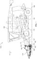
- Fig. 1
- illustrates an agricultural harvester in side view in accordance with the present invention showing the location of the gauge/transport wheels in their harvesting (i.e. gauge wheel) position.
- Fig. 2
- illustrates the agricultural harvester of
Figure 1 in perspective view and showing details of the agricultural harvesting head. - Fig. 3
- is a fractional perspective underneath front view of the left frame section of the agricultural harvesting head of
Figures 1-2 showing the gauge arrangement in a field position. - Fig. 4
- is a fractional perspective underneath view of the left frame section of the agricultural harvesting head of
Figures 1-3 showing the gauge wheel arrangement in a transport position. - Fig. 5
- is an exploded underneath perspective view of the arrangement of
Figure 4 . - Fig. 6
- is an exploded overhead perspective view of the arrangement of
Figure 4 . - In
Figure 1 , anagricultural harvester 100 comprises anagricultural combine 102 and anagricultural harvesting head 104. Theagricultural combine 102 comprises achassis 106 which is supported on fourground supports 108, as well as a threshing andseparating system 112, acleaning system 114, and afeederhouse 110 extending forward from the front of theagricultural combine 102. Theagricultural combine 102 further comprises a grain storage chamber (also known as a "grain tank" or "grain reservoir") that is disposed at the top of theagricultural combine 102 and receives grain that has been threshed, separated, and cleaned. - The
agricultural combine 102 is a self-propelled vehicle which is driven over the ground by a power source such as electric motors or internal combustion engines. The ground supports 108 are preferably wheels or tracks. At least two of them are driven in rotation by motors to propel theagricultural combine 102 over the ground. - The
feederhouse 110 is pivotally connected to the front of the agricultural combine and extends forward therefrom. Thefeederhouse 110 is generally in the form of a hollow and generally rectangular box having an endless belt conveyor disposed inside. The hollow rectangular box has an open forward end and an open rear end. The forward end of thefeederhouse 110 defines a generallyrectangular frame 116 that is configured to support theagricultural harvesting head 104. Afront roller 118 is disposed immediately inside theframe 116. A correspondingrear roller 120 is disposed at the rear end of thefeederhouse 110. Thefront roller 118 and therear roller 120 support opposing ends of aconveyor belt 122. Each of thefront roller 118 and therear roller 120 may be in the form of a narrow shaft with a plurality of sprockets or gears that engage the inner surface of theconveyor belt 122. A rotary motor (electric or hydraulic) is coupled to therear roller 120 to drive therear roller 120 in rotation. This rotation causes theconveyor belt 122 to recirculate in an endless fashion around thefront roller 118 and therear roller 120. Theconveyor belt 122 has protrusions, such as cleats or lugs that engage a top surface of a mat of cut crop (not shown) that is presented to theframe 116. The movement of theconveyor belt 122 draws the mat into the feederhouse and carries it upward on the floor of the feederhouse until it is conveyed through the open rear end of thefeederhouse 110 and sent to the threshing, separating and cleaning systems of theagricultural combine 102. - The
frame 116 is generally rectangular and includes a top member and a bottom member that are generally parallel to each other, are spaced apart, and extend generally parallel to the longitudinal extent of theagricultural harvesting head 104, and extend horizontally. That extends side to side a bottom horizontal member that is parallel to the top horizontal member. Theframe 116 also includes a left side member and a right side member that are parallel to each other, spaced apart, and extend vertically. - The
agricultural harvesting head 104 includes a laterally extendingmain frame 124 that extends perpendicular to a fore-and-aft harvesting direction of travel "V" of theagricultural harvester 100 and perpendicular to the longitudinal axis of theagricultural combine 102. Theagricultural harvesting head 104 further includes anelongate reciprocating knife 128 that extends across almost the entire width of theagricultural harvesting head 104. This reciprocating knife is disposed immediately in front of three cut crop conveyors. These three cut crop conveyors include aleft side conveyor 130 that carries cut crop from the left side of theagricultural harvesting head 104 to a central region of theagricultural harvesting head 104, aright side conveyor 132 that carries crop from the right side of theagricultural harvesting head 104 to the central region of theagricultural harvesting head 104, and acentral conveyor 134 that receives crop from theleft side conveyor 130 and theright side conveyor 132, and conveys the cut crop rearward and underneath adrum conveyor 136. Each of these three conveyors is an endless belt conveyor and is disposed immediately behind thereciprocating knife 128 to receive crop cut by the reciprocatingknife 128. - The laterally extending
main frame 124 includes three frame sections that are coupled together to pivot with respect to each other about fore-and-aft extending axes.Left frame section 138 extends from the outer left end of the agricultural harvesting head to a central region of theagricultural harvesting head 104. Center frame section 140 extends across a middle portion of theagricultural harvesting head 104. Right frame section 142 extends from the outer right end of theagricultural harvesting head 104 to the central region of theagricultural harvesting head 104. - The left side of
conveyor 130 is supported on theleft frame section 138. Several rollers, including aproximal roller 202 adjacent to the center frame section 140 anddistal roller 204 adjacent to the leftmost end of theleft frame section 138 are provided to support anendless belt 206. A motor (not shown) drives theproximal roller 202 in rotation. Theproximal roller 202 recirculates in turn theendless belt 206 about theproximal roller 202 and thedistal roller 204. Crop material cut by the reciprocatingknife 128 in front of theleft frame section 138 falls upon the top surface of theendless belt 206 and is drawn toward the center frame section 140. - The inner end of the
left frame section 138 is connected to the center frame section 140 to pivot up and down at its outer end with respect to the center frame section 140. The inner end of the right frame section 142 is connected to the center frame section 140 to pivot up and down at its outer end with respect to the center frame section 140. - A
gauge wheel assembly 300 is fixed to theleft frame section 138. A similar gauge wheel assembly (in mirror image form) is fixed to the right frame section 142. In the discussion below, we will explain the construction and operation of thegauge wheel assembly 300. The same explanation is true of the gauge wheel assembly (not shown) on the right frame section 142. For ease of explanation we will not duplicate the description of the gauge wheel assembly on the right frame section 142. - The
gauge wheel assembly 300 comprises afirst wheel 302, asecond wheel 304, anelongate truss 306, anelongate truss 307, a first pivot joint 308, and asecond pivot joint 310. Theelongate truss 306 and theelongate truss 307 are formed as flat trusses that share acommon bottom chord 316.Elongate truss 306 includes thebottom chord 316 and atop chord 318.Elongate truss 307 includes thebottom chord 316 and atop chord 320.Trusses common bottom chord 316 at an angle with respect to each other. This angle is preferably 90°. The wheels are fixed to opposing ends of thecommon bottom chord 316. - The
elongate truss 306 includes aweb 322 comprised of several elongate members that are joined at their ends and joined to thebottom chord 316 and thetop chord 318 to form triangular regions in the otherwise open area between the triangle formed by the bottom for 316 in thetop chord 318. Theweb 322 enhances the stiffness and rigidity of theelongate truss 306. - The chords of both trusses and the
web 322 are preferably made of elongate tubular members, such as steel tubes. - When the
gauge wheel assembly 300 is in a harvesting position (seeFigure 3 ), theelongate truss 307 is erect (i.e. generally vertical) and theelongate truss 306 is not erect (i.e. generally horizontal). In this position, thefirst wheel 302 and thesecond wheel 304 support at least a portion of the weight of theleft frame section 138 and the erectelongate truss 307 resists bending of thegauge wheel assembly 300 by the ground forces applied by the wheels to the ends of thebottom chord 316. These ground forces are applied vertically upward through the wheels to the outer ends of theelongate truss 307. These ground forces lie in the plane of theelongate truss 307, which is erect. - When the
gauge wheel assembly 300 is in a transport position (seeFigure 4 ) theelongate truss 306 is erect (i.e. generally vertical) and theelongate truss 307 is not erect (i.e. generally horizontal). In this position, thefirst wheel 302 and thesecond wheel 304 support at least a portion of the weight of theleft frame section 138 and the erectelongate truss 306 resists bending thegauge wheel assembly 300 by the ground forces applied by the wheels to the ends of thebottom chord 316. These ground forces are applied vertically upward through the wheels to the outer ends of theelongate truss 306. These ground forces lie in the plane of theelongate truss 306, which is erect. - The
gauge wheel assembly 300 is configured such that it can be pivoted as a single unitary member from its harvesting position to its transport position. This capability is provided by the first pivot joint 308 and thesecond pivot joint 310. - The first pivot joint 308 is coupled between the
elongate truss 306 and theleft frame section 138 to permit thegauge wheel assembly 300 to pivot about apivot axis 324. When thegauge wheel assembly 300 is in the harvesting position, thepivot axis 324 extends in a direction transverse to the direction of travel "V", parallel to the longitudinal extent of theleft frame section 138, parallel to the longitudinal extent of thebottom chord 316, and parallel to the rotational axes of thefirst wheel 302 and thesecond wheel 304. - The second pivot joint 310 is coupled between the
elongate truss 306 and theleft frame section 138 to permit thegauge wheel assembly 300 to pivot about avertical pivot axis 326. When thegauge wheel assembly 300 is in the harvesting position and in the transport position, thepivot axis 324 extends vertically. - The first pivot joint 308 includes two cylindrical members that are fixed to a
first plate 332. Two mating cylindrical members are fixed to an upper portion ofelongate truss 306. The two mating cylindrical members pivot with respect to the two cylindrical members about theircommon axis 324. In this manner, theelongate truss 306 pivots with respect to theplate 332. The second pivot joint 310 includes a verticalcylindrical member 334 that is fixed to, extends upward from, and is normal to an upper surface offirst plate 332. The verticalcylindrical member 334 extends through a correspondingcylindrical aperture 336 in amating plate 338 that is fixed to the bottom of theleft frame section 138. - Several washers and a
fastener 340 are attached to a free end of the verticalcylindrical member 334 that extends above an upper surface of theleft frame section 138. These washers and fastener secure the gauge wheel assembly to theleft frame section 138, while permitting relative rotation of the verticalcylindrical member 334 with respect to thecylindrical aperture 336. - The
first wheel 302 and thesecond wheel 304 may be solid or composite. They may include a rim to which an inflatable tire is attached. They may include a rim to which a solid tire is attached. They have a diameter between 30 cm and 50 cm. They have a hub that is configured to be supported for free rotation about the end of theelongate truss 306. - Each wheel is connected to its corresponding end of the
bottom chord 316 with a corresponding offsetlink 342. - The
first wheel 302 and thesecond wheel 304 support at least a portion of the weight of theleft frame section 138 when the agricultural harvester is traveling over the ground harvesting crops. In another mode of operation, the wheels may support the entire weight of theleft frame section 138 during harvesting, thereby permitting thereciprocating knife 128 to be raised above the ground. - The
elongate truss 306 extends between thefirst wheel 302 and thesecond wheel 304. Both thefirst wheel 302 and thesecond wheel 304 are fixed for rotation on the opposing ends of theelongate truss 306. Theelongate truss 306 is pivotally coupled to the bottom of theleft frame section 138. - In the discussion above, various components and axes are described as extending in a fore-and-aft direction, or extending in a direction parallel to a direction of travel "V", or extending horizontally or longitudinally, will or extending laterally. During normal operation, these components are expected to move. Typically, they can be pivoted or tilted with respect to each other, with respect to the ground, or with respect to the combine during normal operation and therefore are not precisely horizontal, vertical, longitudinally extending or laterally extending.
- In the discussion above we have described in detail the
gauge wheel assembly 300, how it is attached to theleft frame section 138, and how it operates. An identical gauge wheel assembly is constructed, operated, and attached to theright frame section 138 in a mirror location on the right frame section 142. We have not separately illustrated and described this gauge wheel assembly. - The drawings and discussion above are provided to illustrate and explain at least one way of making and use the invention in such detail to enable someone skilled in the art to make and use it. The claims describe the invention itself.
Claims (15)
- An agricultural harvesting head for an agricultural harvester comprising:a left frame section disposed to receive crop harvested on a left side of the agricultural harvesting head;a right frame section disposed to receive crop harvested on the right side of the agricultural harvesting head;a center frame section that is coupled to and disposed to receive the crop harvested from the left frame section and from the right frame section; anda first gauge wheel assembly coupled to at least one section of the left frame section and the right frame section that is convertible from (A) a harvesting position in which the first gauge wheel assembly supports the at least one section during crop harvesting, to (B) a transport position in which the first gauge wheel assembly supports the at least one section for road transport.
- The agricultural harvesting head of Claim 1, wherein the first gauge wheel assembly comprises:an elongate truss having a first end and a second end;a first wheel fixed to the first end of the elongate truss; anda second wheel fixed to the second end of the elongate truss.
- The agricultural harvesting head of Claim 2, further comprising:a first pivot joint coupled between the elongate truss and the at least one section that permits the elongate truss and the first and second wheels to pivot as an assembly about a first pivot axis that extends parallel to a longitudinal extent of the at least one section; anda second pivot joint coupled between the elongate truss and the at least one section that permits the elongate truss and the wheels to pivot as an assembly about a second pivot axis that extends vertically.
- The agricultural harvesting head of Claim 2, wherein the elongate truss comprises a bottom chord, a first top chord fixed to the bottom chord, and a web interconnecting the bottom chord and the first top chord when the first gauge wheel assembly is in the transport position.
- The agricultural harvesting head of Claim 4, wherein the elongate truss comprises the bottom chord, and a second top chord fixed to the bottom chord wherein the second top chord is different than the first top chord.
- The agricultural harvesting head of Claim 4, wherein the first pivot joint is coupled to an apex of the first top chord to permit the elongate truss to pivot about a vertical axis when the first gauge wheel assembly is in a transport position.
- The agricultural harvesting head of Claim 1, wherein the first gauge wheel assembly comprises a first truss and a second truss, wherein the first truss and the second truss share a bottom chord, and wherein the first truss has a first top chord, and the second truss has a second top chord.
- The agricultural harvesting head of Claim 7, wherein the first truss and the second truss are fixed at a right angle to each other, and further wherein the bottom chord extends parallel to a direction of travel "V" of the agricultural harvester in the harvesting position and extends parallel to the direction of travel "V" of the agricultural harvester in the transport position.
- The agricultural harvesting head of Claim 7, wherein the first truss is erect when the first gauge wheel assembly is in the transport position, and wherein the second truss is erect when the first gauge wheel assembly is in the harvesting position.
- An agricultural harvester comprising:an agricultural combine; andan agricultural harvesting head supported on the front of the agricultural combine, wherein the agricultural harvesting head is described in Claim 1.
- The agricultural harvesting head of Claim 2, wherein the first and second wheels are spaced apart a first distance in the harvesting position and are spaced apart the same distance in a transport position.
- The agricultural harvesting head of Claim 2, wherein the first and second wheels are fixed in position relative to each other as they move from the harvesting position to the transport position.
- The agricultural harvesting head of Claim 2, wherein each of the first and second wheels wheels are supported on an offsetting link that in turn is supported on the elongate truss such that each of the wheels rotates about an axis that is generally parallel to and offset from a bottom chord of the elongate truss.
- The agricultural harvesting head of Claim 2, wherein the elongate truss is generally triangular and has an apex disposed midway between and above the first end and the second end and/or(a) wherein the elongate truss has a longitudinal extent, and further wherein the second pivot joint constrains the elongate truss to pivot about a vertical axis that is perpendicular to the longitudinal extent of the elongate truss and equidistant from the first wheel and the second wheel and/or(b) wherein a weight of the at least one section is supported on the apex of the elongate truss when the elongate truss is in the transport position.
- The agricultural harvesting head of Claim 3, wherein the second pivot axis is disposed equidistant to the first wheel and the second wheel.
Applications Claiming Priority (1)
| Application Number | Priority Date | Filing Date | Title |
|---|---|---|---|
| US15/499,956 US10405481B2 (en) | 2017-04-28 | 2017-04-28 | Agricultural harvesting head with a gauge and transport wheel arrangement |
Publications (2)
| Publication Number | Publication Date |
|---|---|
| EP3395156A1 true EP3395156A1 (en) | 2018-10-31 |
| EP3395156B1 EP3395156B1 (en) | 2020-05-13 |
Family
ID=62067478
Family Applications (1)
| Application Number | Title | Priority Date | Filing Date |
|---|---|---|---|
| EP18169483.7A Active EP3395156B1 (en) | 2017-04-28 | 2018-04-26 | An agricultural harvesting head with a gauge and transport wheel arrangement |
Country Status (3)
| Country | Link |
|---|---|
| US (1) | US10405481B2 (en) |
| EP (1) | EP3395156B1 (en) |
| BR (1) | BR102018004547B1 (en) |
Cited By (3)
| Publication number | Priority date | Publication date | Assignee | Title |
|---|---|---|---|---|
| EP3861848A1 (en) * | 2020-02-04 | 2021-08-11 | Deere & Company | Integrated transport systems with kingpin steering |
| US11124232B2 (en) | 2018-08-15 | 2021-09-21 | Deere & Company | Integrated transport systems with kingpin steering |
| US20220183202A1 (en) * | 2020-12-11 | 2022-06-16 | Deere & Company | Integrated transport coupling system |
Families Citing this family (11)
| Publication number | Priority date | Publication date | Assignee | Title |
|---|---|---|---|---|
| US10375881B2 (en) * | 2017-05-23 | 2019-08-13 | Cnh Industrial America Llc | Agricultural machine with sectional header |
| US10980181B2 (en) * | 2018-10-18 | 2021-04-20 | Cnh Industrial America Llc | Lateral transport assembly for an agricultural header |
| EP3669624B1 (en) * | 2018-12-17 | 2023-09-20 | CNH Industrial Belgium NV | A combine header equipped with an automated header transport system and header steering mechanism |
| EP3669626B1 (en) * | 2018-12-17 | 2021-08-18 | CNH Industrial Belgium NV | A combine header equipped with an automated header transport system |
| EP3669625B1 (en) * | 2018-12-17 | 2023-08-16 | CNH Industrial Belgium NV | A combine header equipped with an automated header transport system and drawbar |
| US11058056B2 (en) | 2019-05-06 | 2021-07-13 | Deere & Company | Gang arm gauge wheel height control for crop harvesting device |
| US11277967B2 (en) * | 2019-07-25 | 2022-03-22 | Deere & Company | Harvester transport preparation |
| US20210176919A1 (en) * | 2019-12-17 | 2021-06-17 | Stephen P. Hurley | Field Cart |
| US11606903B2 (en) * | 2020-04-01 | 2023-03-21 | Macdon Industries Ltd. | Transport wheel arrangement for a crop harvesting header |
| US20210307233A1 (en) * | 2020-04-01 | 2021-10-07 | Macdon Industries Ltd. | Transport wheel arrangement for a crop harvesting header |
| US11490564B2 (en) | 2020-06-25 | 2022-11-08 | Deere & Company | Draper transport lift assist system |
Citations (4)
| Publication number | Priority date | Publication date | Assignee | Title |
|---|---|---|---|---|
| US4089430A (en) * | 1977-05-27 | 1978-05-16 | Gosselin Andrew F | Farm implement trailer |
| US5031394A (en) * | 1989-07-10 | 1991-07-16 | Honey Bee Manufacturing Ltd. | Swather attachment for bi-directional tractor |
| US5243810A (en) | 1991-10-28 | 1993-09-14 | Macdon Industries | Header transport system |
| EP1905294A1 (en) * | 2006-09-29 | 2008-04-02 | CLAAS Selbstfahrende Erntemaschinen GmbH | Agricultural working machine |
Family Cites Families (11)
| Publication number | Priority date | Publication date | Assignee | Title |
|---|---|---|---|---|
| US3457709A (en) * | 1967-01-30 | 1969-07-29 | Killbery Ind Ltd | Pull-type swather |
| AT303434B (en) * | 1970-08-19 | 1972-11-27 | Epple Buxbaum Werke | Harvesting machine with a removable cutting or picking attachment |
| US3721461A (en) * | 1971-08-27 | 1973-03-20 | Deere & Co | Apparatus and method for converting an implement between operating and transport positions |
| US4026365A (en) * | 1975-11-10 | 1977-05-31 | International Harvester Company | Caster wheel supported agricultural implement with self-locking caster wheel |
| CA1188899A (en) * | 1984-05-28 | 1985-06-18 | George E. Bourgault | Automatic swather transport system |
| US6209297B1 (en) | 1999-05-28 | 2001-04-03 | Deere & Company | Header for a harvester having an integral transport system |
| US7197865B1 (en) * | 2005-12-22 | 2007-04-03 | Macdon Industries Ltd. | Self contained transport for crop harvesting header |
| US7926249B1 (en) * | 2009-11-17 | 2011-04-19 | Cnh America Llc | Transport system for a harvest header |
| US8025312B1 (en) * | 2010-06-17 | 2011-09-27 | Agco Corporation | Agricultural header transport kit |
| CZ2012959A3 (en) * | 2012-12-25 | 2014-07-02 | Farmet A.S. | Semi-mounted or towed agricultural soil working machine or seed drill |
| US10278330B2 (en) * | 2016-10-11 | 2019-05-07 | Deere & Company | Combine feeder house gauge wheels |
-
2017
- 2017-04-28 US US15/499,956 patent/US10405481B2/en active Active
-
2018
- 2018-03-07 BR BR102018004547-4A patent/BR102018004547B1/en active IP Right Grant
- 2018-04-26 EP EP18169483.7A patent/EP3395156B1/en active Active
Patent Citations (4)
| Publication number | Priority date | Publication date | Assignee | Title |
|---|---|---|---|---|
| US4089430A (en) * | 1977-05-27 | 1978-05-16 | Gosselin Andrew F | Farm implement trailer |
| US5031394A (en) * | 1989-07-10 | 1991-07-16 | Honey Bee Manufacturing Ltd. | Swather attachment for bi-directional tractor |
| US5243810A (en) | 1991-10-28 | 1993-09-14 | Macdon Industries | Header transport system |
| EP1905294A1 (en) * | 2006-09-29 | 2008-04-02 | CLAAS Selbstfahrende Erntemaschinen GmbH | Agricultural working machine |
Cited By (4)
| Publication number | Priority date | Publication date | Assignee | Title |
|---|---|---|---|---|
| US11124232B2 (en) | 2018-08-15 | 2021-09-21 | Deere & Company | Integrated transport systems with kingpin steering |
| US11178806B2 (en) | 2018-08-15 | 2021-11-23 | Deere & Company | Combined gage wheel and integrated transport system |
| EP3861848A1 (en) * | 2020-02-04 | 2021-08-11 | Deere & Company | Integrated transport systems with kingpin steering |
| US20220183202A1 (en) * | 2020-12-11 | 2022-06-16 | Deere & Company | Integrated transport coupling system |
Also Published As
| Publication number | Publication date |
|---|---|
| US20180310462A1 (en) | 2018-11-01 |
| US10405481B2 (en) | 2019-09-10 |
| BR102018004547A2 (en) | 2018-11-21 |
| EP3395156B1 (en) | 2020-05-13 |
| BR102018004547B1 (en) | 2022-11-16 |
Similar Documents
| Publication | Publication Date | Title |
|---|---|---|
| EP3395156B1 (en) | An agricultural harvesting head with a gauge and transport wheel arrangement | |
| EP3398426B1 (en) | Multilink connection between harvesting head adapter frame and mainframe | |
| EP3469878B1 (en) | Roll center for harvester attachment frame control arms | |
| US6775969B2 (en) | Foldable harvesting header | |
| EP3308624B1 (en) | Combine feeder house gauge wheels | |
| US6745550B1 (en) | Sugar cane harvester having an arrangement for steering the crop dividers and topper mechanism together with the wheels | |
| EP3406130B1 (en) | Agricultural machine with sectional header | |
| US20170202146A1 (en) | Continuous windrow merger | |
| DE3006871A1 (en) | SELF-DRIVING COMBINATION | |
| EP3395155B1 (en) | Multi-section header with offset pivot axis | |
| EP3400779B1 (en) | Harvesting head constant lifting force assembly | |
| US20080168755A1 (en) | Harvesting Implement, Particularly Front Harvesting Attachment For Agricultural Harvesting Machines For Taking Up Cereal Crops and Conveying It Further | |
| EP2997811B1 (en) | Multi-purpose spreader of an agricultural vehicle | |
| US10980181B2 (en) | Lateral transport assembly for an agricultural header | |
| EP3659427B1 (en) | Laterally offset transport wheels on harvesting header | |
| BR102018017123B1 (en) | AGRICULTURAL PLATFORM | |
| US1728886A (en) | Auxiliary feeding attachment for combined harvesters and thrashers | |
| US20200390034A1 (en) | Three-Section Crop Header with Drapers and Top Cross Auger | |
| JP3743722B2 (en) | Combine harvester | |
| BR102018017123A2 (en) | AGRICULTURAL PLATFORM WITH ONE OR MORE MOBILE WING SECTIONS | |
| BR112020004972B1 (en) | PLATFORM FOR AN AGRICULTURAL VEHICLE AND AGRICULTURAL VEHICLE | |
| BR112020004972A2 (en) | agricultural platform with constant cutter and coil ratio |
Legal Events
| Date | Code | Title | Description |
|---|---|---|---|
| PUAI | Public reference made under article 153(3) epc to a published international application that has entered the european phase |
Free format text: ORIGINAL CODE: 0009012 |
|
| STAA | Information on the status of an ep patent application or granted ep patent |
Free format text: STATUS: THE APPLICATION HAS BEEN PUBLISHED |
|
| AK | Designated contracting states |
Kind code of ref document: A1 Designated state(s): AL AT BE BG CH CY CZ DE DK EE ES FI FR GB GR HR HU IE IS IT LI LT LU LV MC MK MT NL NO PL PT RO RS SE SI SK SM TR |
|
| AX | Request for extension of the european patent |
Extension state: BA ME |
|
| STAA | Information on the status of an ep patent application or granted ep patent |
Free format text: STATUS: REQUEST FOR EXAMINATION WAS MADE |
|
| 17P | Request for examination filed |
Effective date: 20190430 |
|
| RBV | Designated contracting states (corrected) |
Designated state(s): AL AT BE BG CH CY CZ DE DK EE ES FI FR GB GR HR HU IE IS IT LI LT LU LV MC MK MT NL NO PL PT RO RS SE SI SK SM TR |
|
| STAA | Information on the status of an ep patent application or granted ep patent |
Free format text: STATUS: EXAMINATION IS IN PROGRESS |
|
| 17Q | First examination report despatched |
Effective date: 20190709 |
|
| GRAP | Despatch of communication of intention to grant a patent |
Free format text: ORIGINAL CODE: EPIDOSNIGR1 |
|
| STAA | Information on the status of an ep patent application or granted ep patent |
Free format text: STATUS: GRANT OF PATENT IS INTENDED |
|
| INTG | Intention to grant announced |
Effective date: 20191023 |
|
| GRAS | Grant fee paid |
Free format text: ORIGINAL CODE: EPIDOSNIGR3 |
|
| GRAA | (expected) grant |
Free format text: ORIGINAL CODE: 0009210 |
|
| STAA | Information on the status of an ep patent application or granted ep patent |
Free format text: STATUS: THE PATENT HAS BEEN GRANTED |
|
| AK | Designated contracting states |
Kind code of ref document: B1 Designated state(s): AL AT BE BG CH CY CZ DE DK EE ES FI FR GB GR HR HU IE IS IT LI LT LU LV MC MK MT NL NO PL PT RO RS SE SI SK SM TR |
|
| REG | Reference to a national code |
Ref country code: GB Ref legal event code: FG4D |
|
| REG | Reference to a national code |
Ref country code: CH Ref legal event code: EP |
|
| REG | Reference to a national code |
Ref country code: DE Ref legal event code: R096 Ref document number: 602018004381 Country of ref document: DE |
|
| REG | Reference to a national code |
Ref country code: AT Ref legal event code: REF Ref document number: 1268983 Country of ref document: AT Kind code of ref document: T Effective date: 20200615 |
|
| REG | Reference to a national code |
Ref country code: LT Ref legal event code: MG4D |
|
| REG | Reference to a national code |
Ref country code: NL Ref legal event code: MP Effective date: 20200513 |
|
| PG25 | Lapsed in a contracting state [announced via postgrant information from national office to epo] |
Ref country code: FI Free format text: LAPSE BECAUSE OF FAILURE TO SUBMIT A TRANSLATION OF THE DESCRIPTION OR TO PAY THE FEE WITHIN THE PRESCRIBED TIME-LIMIT Effective date: 20200513 Ref country code: GR Free format text: LAPSE BECAUSE OF FAILURE TO SUBMIT A TRANSLATION OF THE DESCRIPTION OR TO PAY THE FEE WITHIN THE PRESCRIBED TIME-LIMIT Effective date: 20200814 Ref country code: NO Free format text: LAPSE BECAUSE OF FAILURE TO SUBMIT A TRANSLATION OF THE DESCRIPTION OR TO PAY THE FEE WITHIN THE PRESCRIBED TIME-LIMIT Effective date: 20200813 Ref country code: IS Free format text: LAPSE BECAUSE OF FAILURE TO SUBMIT A TRANSLATION OF THE DESCRIPTION OR TO PAY THE FEE WITHIN THE PRESCRIBED TIME-LIMIT Effective date: 20200913 Ref country code: PT Free format text: LAPSE BECAUSE OF FAILURE TO SUBMIT A TRANSLATION OF THE DESCRIPTION OR TO PAY THE FEE WITHIN THE PRESCRIBED TIME-LIMIT Effective date: 20200914 Ref country code: SE Free format text: LAPSE BECAUSE OF FAILURE TO SUBMIT A TRANSLATION OF THE DESCRIPTION OR TO PAY THE FEE WITHIN THE PRESCRIBED TIME-LIMIT Effective date: 20200513 Ref country code: LT Free format text: LAPSE BECAUSE OF FAILURE TO SUBMIT A TRANSLATION OF THE DESCRIPTION OR TO PAY THE FEE WITHIN THE PRESCRIBED TIME-LIMIT Effective date: 20200513 |
|
| PG25 | Lapsed in a contracting state [announced via postgrant information from national office to epo] |
Ref country code: HR Free format text: LAPSE BECAUSE OF FAILURE TO SUBMIT A TRANSLATION OF THE DESCRIPTION OR TO PAY THE FEE WITHIN THE PRESCRIBED TIME-LIMIT Effective date: 20200513 Ref country code: LV Free format text: LAPSE BECAUSE OF FAILURE TO SUBMIT A TRANSLATION OF THE DESCRIPTION OR TO PAY THE FEE WITHIN THE PRESCRIBED TIME-LIMIT Effective date: 20200513 Ref country code: BG Free format text: LAPSE BECAUSE OF FAILURE TO SUBMIT A TRANSLATION OF THE DESCRIPTION OR TO PAY THE FEE WITHIN THE PRESCRIBED TIME-LIMIT Effective date: 20200813 Ref country code: RS Free format text: LAPSE BECAUSE OF FAILURE TO SUBMIT A TRANSLATION OF THE DESCRIPTION OR TO PAY THE FEE WITHIN THE PRESCRIBED TIME-LIMIT Effective date: 20200513 |
|
| REG | Reference to a national code |
Ref country code: AT Ref legal event code: MK05 Ref document number: 1268983 Country of ref document: AT Kind code of ref document: T Effective date: 20200513 |
|
| PG25 | Lapsed in a contracting state [announced via postgrant information from national office to epo] |
Ref country code: NL Free format text: LAPSE BECAUSE OF FAILURE TO SUBMIT A TRANSLATION OF THE DESCRIPTION OR TO PAY THE FEE WITHIN THE PRESCRIBED TIME-LIMIT Effective date: 20200513 Ref country code: AL Free format text: LAPSE BECAUSE OF FAILURE TO SUBMIT A TRANSLATION OF THE DESCRIPTION OR TO PAY THE FEE WITHIN THE PRESCRIBED TIME-LIMIT Effective date: 20200513 |
|
| PG25 | Lapsed in a contracting state [announced via postgrant information from national office to epo] |
Ref country code: AT Free format text: LAPSE BECAUSE OF FAILURE TO SUBMIT A TRANSLATION OF THE DESCRIPTION OR TO PAY THE FEE WITHIN THE PRESCRIBED TIME-LIMIT Effective date: 20200513 Ref country code: DK Free format text: LAPSE BECAUSE OF FAILURE TO SUBMIT A TRANSLATION OF THE DESCRIPTION OR TO PAY THE FEE WITHIN THE PRESCRIBED TIME-LIMIT Effective date: 20200513 Ref country code: IT Free format text: LAPSE BECAUSE OF FAILURE TO SUBMIT A TRANSLATION OF THE DESCRIPTION OR TO PAY THE FEE WITHIN THE PRESCRIBED TIME-LIMIT Effective date: 20200513 Ref country code: SM Free format text: LAPSE BECAUSE OF FAILURE TO SUBMIT A TRANSLATION OF THE DESCRIPTION OR TO PAY THE FEE WITHIN THE PRESCRIBED TIME-LIMIT Effective date: 20200513 Ref country code: EE Free format text: LAPSE BECAUSE OF FAILURE TO SUBMIT A TRANSLATION OF THE DESCRIPTION OR TO PAY THE FEE WITHIN THE PRESCRIBED TIME-LIMIT Effective date: 20200513 Ref country code: CZ Free format text: LAPSE BECAUSE OF FAILURE TO SUBMIT A TRANSLATION OF THE DESCRIPTION OR TO PAY THE FEE WITHIN THE PRESCRIBED TIME-LIMIT Effective date: 20200513 Ref country code: RO Free format text: LAPSE BECAUSE OF FAILURE TO SUBMIT A TRANSLATION OF THE DESCRIPTION OR TO PAY THE FEE WITHIN THE PRESCRIBED TIME-LIMIT Effective date: 20200513 Ref country code: ES Free format text: LAPSE BECAUSE OF FAILURE TO SUBMIT A TRANSLATION OF THE DESCRIPTION OR TO PAY THE FEE WITHIN THE PRESCRIBED TIME-LIMIT Effective date: 20200513 |
|
| REG | Reference to a national code |
Ref country code: DE Ref legal event code: R097 Ref document number: 602018004381 Country of ref document: DE |
|
| PG25 | Lapsed in a contracting state [announced via postgrant information from national office to epo] |
Ref country code: PL Free format text: LAPSE BECAUSE OF FAILURE TO SUBMIT A TRANSLATION OF THE DESCRIPTION OR TO PAY THE FEE WITHIN THE PRESCRIBED TIME-LIMIT Effective date: 20200513 Ref country code: SK Free format text: LAPSE BECAUSE OF FAILURE TO SUBMIT A TRANSLATION OF THE DESCRIPTION OR TO PAY THE FEE WITHIN THE PRESCRIBED TIME-LIMIT Effective date: 20200513 |
|
| PLBE | No opposition filed within time limit |
Free format text: ORIGINAL CODE: 0009261 |
|
| STAA | Information on the status of an ep patent application or granted ep patent |
Free format text: STATUS: NO OPPOSITION FILED WITHIN TIME LIMIT |
|
| 26N | No opposition filed |
Effective date: 20210216 |
|
| PG25 | Lapsed in a contracting state [announced via postgrant information from national office to epo] |
Ref country code: SI Free format text: LAPSE BECAUSE OF FAILURE TO SUBMIT A TRANSLATION OF THE DESCRIPTION OR TO PAY THE FEE WITHIN THE PRESCRIBED TIME-LIMIT Effective date: 20200513 |
|
| PG25 | Lapsed in a contracting state [announced via postgrant information from national office to epo] |
Ref country code: MC Free format text: LAPSE BECAUSE OF FAILURE TO SUBMIT A TRANSLATION OF THE DESCRIPTION OR TO PAY THE FEE WITHIN THE PRESCRIBED TIME-LIMIT Effective date: 20200513 |
|
| PG25 | Lapsed in a contracting state [announced via postgrant information from national office to epo] |
Ref country code: LU Free format text: LAPSE BECAUSE OF NON-PAYMENT OF DUE FEES Effective date: 20210426 |
|
| REG | Reference to a national code |
Ref country code: BE Ref legal event code: MM Effective date: 20210430 |
|
| PG25 | Lapsed in a contracting state [announced via postgrant information from national office to epo] |
Ref country code: FR Free format text: LAPSE BECAUSE OF NON-PAYMENT OF DUE FEES Effective date: 20210430 Ref country code: LI Free format text: LAPSE BECAUSE OF NON-PAYMENT OF DUE FEES Effective date: 20210430 Ref country code: CH Free format text: LAPSE BECAUSE OF NON-PAYMENT OF DUE FEES Effective date: 20210430 |
|
| PG25 | Lapsed in a contracting state [announced via postgrant information from national office to epo] |
Ref country code: IE Free format text: LAPSE BECAUSE OF NON-PAYMENT OF DUE FEES Effective date: 20210426 |
|
| PG25 | Lapsed in a contracting state [announced via postgrant information from national office to epo] |
Ref country code: BE Free format text: LAPSE BECAUSE OF NON-PAYMENT OF DUE FEES Effective date: 20210430 |
|
| GBPC | Gb: european patent ceased through non-payment of renewal fee |
Effective date: 20220426 |
|
| PG25 | Lapsed in a contracting state [announced via postgrant information from national office to epo] |
Ref country code: GB Free format text: LAPSE BECAUSE OF NON-PAYMENT OF DUE FEES Effective date: 20220426 |
|
| PG25 | Lapsed in a contracting state [announced via postgrant information from national office to epo] |
Ref country code: CY Free format text: LAPSE BECAUSE OF FAILURE TO SUBMIT A TRANSLATION OF THE DESCRIPTION OR TO PAY THE FEE WITHIN THE PRESCRIBED TIME-LIMIT Effective date: 20200513 |
|
| PG25 | Lapsed in a contracting state [announced via postgrant information from national office to epo] |
Ref country code: HU Free format text: LAPSE BECAUSE OF FAILURE TO SUBMIT A TRANSLATION OF THE DESCRIPTION OR TO PAY THE FEE WITHIN THE PRESCRIBED TIME-LIMIT; INVALID AB INITIO Effective date: 20180426 |
|
| PGFP | Annual fee paid to national office [announced via postgrant information from national office to epo] |
Ref country code: DE Payment date: 20230321 Year of fee payment: 6 |