EP3395052B1 - Mobiles konferenzsystem - Google Patents
Mobiles konferenzsystem Download PDFInfo
- Publication number
- EP3395052B1 EP3395052B1 EP16826032.1A EP16826032A EP3395052B1 EP 3395052 B1 EP3395052 B1 EP 3395052B1 EP 16826032 A EP16826032 A EP 16826032A EP 3395052 B1 EP3395052 B1 EP 3395052B1
- Authority
- EP
- European Patent Office
- Prior art keywords
- unit
- mobile
- free
- hands
- mobile hands
- Prior art date
- Legal status (The legal status is an assumption and is not a legal conclusion. Google has not performed a legal analysis and makes no representation as to the accuracy of the status listed.)
- Active
Links
Images




Classifications
-
- H—ELECTRICITY
- H04—ELECTRIC COMMUNICATION TECHNIQUE
- H04M—TELEPHONIC COMMUNICATION
- H04M3/00—Automatic or semi-automatic exchanges
- H04M3/42—Systems providing special services or facilities to subscribers
- H04M3/56—Arrangements for connecting several subscribers to a common circuit, i.e. affording conference facilities
-
- H—ELECTRICITY
- H01—ELECTRIC ELEMENTS
- H01M—PROCESSES OR MEANS, e.g. BATTERIES, FOR THE DIRECT CONVERSION OF CHEMICAL ENERGY INTO ELECTRICAL ENERGY
- H01M50/00—Constructional details or processes of manufacture of the non-active parts of electrochemical cells other than fuel cells, e.g. hybrid cells
- H01M50/20—Mountings; Secondary casings or frames; Racks, modules or packs; Suspension devices; Shock absorbers; Transport or carrying devices; Holders
- H01M50/204—Racks, modules or packs for multiple batteries or multiple cells
- H01M50/207—Racks, modules or packs for multiple batteries or multiple cells characterised by their shape
- H01M50/216—Racks, modules or packs for multiple batteries or multiple cells characterised by their shape adapted for button or coin cells
-
- H—ELECTRICITY
- H01—ELECTRIC ELEMENTS
- H01M—PROCESSES OR MEANS, e.g. BATTERIES, FOR THE DIRECT CONVERSION OF CHEMICAL ENERGY INTO ELECTRICAL ENERGY
- H01M50/00—Constructional details or processes of manufacture of the non-active parts of electrochemical cells other than fuel cells, e.g. hybrid cells
- H01M50/20—Mountings; Secondary casings or frames; Racks, modules or packs; Suspension devices; Shock absorbers; Transport or carrying devices; Holders
- H01M50/247—Mountings; Secondary casings or frames; Racks, modules or packs; Suspension devices; Shock absorbers; Transport or carrying devices; Holders specially adapted for portable devices, e.g. mobile phones, computers, hand tools or pacemakers
-
- H—ELECTRICITY
- H01—ELECTRIC ELEMENTS
- H01M—PROCESSES OR MEANS, e.g. BATTERIES, FOR THE DIRECT CONVERSION OF CHEMICAL ENERGY INTO ELECTRICAL ENERGY
- H01M50/00—Constructional details or processes of manufacture of the non-active parts of electrochemical cells other than fuel cells, e.g. hybrid cells
- H01M50/50—Current conducting connections for cells or batteries
- H01M50/543—Terminals
- H01M50/552—Terminals characterised by their shape
- H01M50/559—Terminals adapted for cells having curved cross-section, e.g. round, elliptic or button cells
-
- H—ELECTRICITY
- H04—ELECTRIC COMMUNICATION TECHNIQUE
- H04M—TELEPHONIC COMMUNICATION
- H04M1/00—Substation equipment, e.g. for use by subscribers
- H04M1/60—Substation equipment, e.g. for use by subscribers including speech amplifiers
- H04M1/6033—Substation equipment, e.g. for use by subscribers including speech amplifiers for providing handsfree use or a loudspeaker mode in telephone sets
-
- H—ELECTRICITY
- H04—ELECTRIC COMMUNICATION TECHNIQUE
- H04M—TELEPHONIC COMMUNICATION
- H04M1/00—Substation equipment, e.g. for use by subscribers
- H04M1/60—Substation equipment, e.g. for use by subscribers including speech amplifiers
- H04M1/62—Constructional arrangements
-
- H—ELECTRICITY
- H04—ELECTRIC COMMUNICATION TECHNIQUE
- H04M—TELEPHONIC COMMUNICATION
- H04M3/00—Automatic or semi-automatic exchanges
- H04M3/42—Systems providing special services or facilities to subscribers
- H04M3/56—Arrangements for connecting several subscribers to a common circuit, i.e. affording conference facilities
- H04M3/563—User guidance or feature selection
- H04M3/564—User guidance or feature selection whereby the feature is a sub-conference
-
- H—ELECTRICITY
- H04—ELECTRIC COMMUNICATION TECHNIQUE
- H04M—TELEPHONIC COMMUNICATION
- H04M2207/00—Type of exchange or network, i.e. telephonic medium, in which the telephonic communication takes place
- H04M2207/18—Type of exchange or network, i.e. telephonic medium, in which the telephonic communication takes place wireless networks
-
- Y—GENERAL TAGGING OF NEW TECHNOLOGICAL DEVELOPMENTS; GENERAL TAGGING OF CROSS-SECTIONAL TECHNOLOGIES SPANNING OVER SEVERAL SECTIONS OF THE IPC; TECHNICAL SUBJECTS COVERED BY FORMER USPC CROSS-REFERENCE ART COLLECTIONS [XRACs] AND DIGESTS
- Y02—TECHNOLOGIES OR APPLICATIONS FOR MITIGATION OR ADAPTATION AGAINST CLIMATE CHANGE
- Y02E—REDUCTION OF GREENHOUSE GAS [GHG] EMISSIONS, RELATED TO ENERGY GENERATION, TRANSMISSION OR DISTRIBUTION
- Y02E60/00—Enabling technologies; Technologies with a potential or indirect contribution to GHG emissions mitigation
- Y02E60/10—Energy storage using batteries
Definitions
- the present invention relates to a mobile conference system.
- a mobile conference system which has a first mobile master hands-free unit and at least one second mobile slave hands-free unit, each having at least one microphone for recording audio signals, a loudspeaker for reproducing audio signals to be reproduced, a battery unit for power supply, an operating unit, at least one lighting unit and a first transmitting / receiving unit for bidirectional wireless communication between the first and second mobile hands-free unit.
- the first hands-free unit has a second transceiver unit for wireless bidirectional audio communication with an external unit.
- the first hands-free unit is configured to wirelessly transmit audio signals received via the second transceiver unit from the external unit to the second mobile hands-free unit by the first transceiver unit.
- the first hands-free unit is configured to receive audio signals, which are transmitted via the first transceiver unit from the second mobile hands-free unit have been mixed with the audio signals recorded via the at least one microphone of the first handsfree unit and wirelessly transmitted by the second transmitter / receiver unit to the external unit.
- the mobile conference system has a first mobile hands-free unit (master) and at least one second mobile hands-free unit (slave).
- the first mobile hands-free unit has an interface for external communication, for example via a mobile telephone or via a landline telephone connection.
- the first mobile hands-free unit (master) has a second wireless interface for wireless bidirectional communication with the at least one second mobile hands-free unit (slave).
- the second mobile hands-free unit (slave) has (as well as the first mobile hands-free optional) at least one microphone for recording an audio signal, at least one speaker for playback of a reproduced audio signal, at least one control element for operating the second mobile handsfree unit, a control unit for controlling the second mobile hands-free unit and a wireless communication interface for bidirectional communication with the first mobile hands-free unit.
- the first mobile hands-free unit receives the audio signals recorded by the microphones of the second mobile hands-free units which have been transmitted via the wireless interface.
- the first mobile hands-free unit receives an external audio signal via the external communication interface and transmits this audio signal wirelessly to the at least one mobile hands-free unit which reproduces the audio signal or at least parts of the audio signal via the loudspeakers.
- the first mobile hands-free unit and the second mobile hands-free unit has at least one lighting unit.
- the operation of these lighting units can be controlled by a control unit of the first mobile hands-free unit (master).
- the lights can be controlled centrally depending on a set operating mode.
- all hands-free units can be muted by operating a muting control.
- This can be represented by the lighting units accordingly.
- the color of the lighting unit, the intensity of the lighting unit and / or the flashing of the lighting unit change as soon as muting of the hands-free units is activated.
- the muting on each of the hands-free units may be activated and / or deactivated.
- Fig. 1 shows a schematic representation of a mobile conference system according to a first embodiment.
- the mobile conference system 1000 has a first mobile hands-free unit (master) 1100 and at least one further or second mobile hands-free unit (slave) 1200.
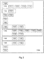
- Fig. 2 shows a block diagram of a first mobile hands-free unit according to a second embodiment.
- the first mobile hands-free unit (master) 1100 has an operating unit 1110 with a first lighting unit 1111, a volume control element 1112, a muting operating element 1113 and / or a pairing operating element 1114.
- the first mobile hands-free unit 1100 has a ground unit 1120 with a second light unit 1121, at least one microphone 1130, at least one loudspeaker 1140, at least one first transceiver 1150.
- the first transceiver 1150 may include a wireless interface, for example, based on the Represent the DECT standard and is used for communication between the first mobile handsfree unit (master) 1100 and the second mobile handsfree units (slave) 1200.
- the first mobile handsfree unit (master) further comprises a second transceiver unit 1160 and a second wireless communication interface 1160.
- the second transceiver 1160 may include a wireless transceiver 1161, for example based on the WiFi protocol or the Bluetooth protocol, and / or a wired transceiver 1162, for example, based on a USB port, an AUX port, a landline etc. have.
- the second transceiver 1160 is for bi-directional transmission of audio signals between the conference system 1000 and an external remote communication unit such as a smartphone.
- the first mobile hands-free unit 1100 further includes a control unit 1170 for controlling the operation of the first and second hands-free units 1100, 1200.
- the control unit 1170 may include a first lighting control unit 1171 for controlling the lighting units of the first and / or second mobile hands-free units, a pairing unit 1172 for initializing and / or controlling a pairing between a mobile telephone and the first mobile hands-free unit.
- the control unit 1170 may further include a volume control unit 1173, an operation control unit 1174, a slave synchronization unit 1175, a mode control unit 1176, and / or a second lighting control unit 1177.
- the first mobile hands-free unit 1100 includes an audio mixing unit 1180 having a first audio activity detection unit 1181 for detecting audio activity via the internal interface 1150 for communication with the second mobile hands-free units 1200 and a second audio activity detection unit 1182 for detecting audio activity via the external interface 1160.
- the first mobile hands-free unit 1100 has a control interface 1190 for the wireless, bidirectional communication of control signals, in particular to the at least one second mobile hands-free unit 1200.
- the control interface 1190 may include an I 2 S unit 1191 and a slave controller 1192.
- the control signals may be embedded in the audio data, and thus the first mobile hands-free unit (master) 1100 may send and receive control signals to and from the second mobile hands-free units (slave) 1200 via its transceiver 1150.
- the control interface 1190 of the first mobile hands-free unit 1100 is thus integrated into the first transmitting / receiving unit 1150.
- the first mobile hands-free unit 1100 has an accumulator unit 1010, from which the hands-free unit 1100 can be supplied with mobile energy.
- Fig. 3 shows a block diagram of a second mobile hands-free unit according to a third embodiment.
- the second mobile hands-free unit 1200 which is configured as a slave, has an operating unit 1210 with a first lighting unit 1211, a volume control element 1212 and / or a muting operating element 1213. Furthermore, the second mobile hands-free unit 1200 has a ground unit 1220 with a lighting unit 1221, at least one microphone 1230, at least one loudspeaker 1240, at least one transmitting / receiving unit or a wireless interface unit 1250 and / or a control unit 1270. Via the transceiver unit 1250, the audio signals detected via the microphone 1230 can be transmitted wirelessly to the first mobile hands-free unit 1100.
- audio signals to be reproduced can be received wirelessly by the first mobile hands-free unit 1100 and played back via the at least one loudspeaker 1240.
- Control signals can be received by the first mobile hands-free unit 1100 via the transmitting / receiving unit 1250 or via a corresponding subunit such as, for example, a control signal receiving unit 1251. These signals can then be converted by means of the control unit 1270.
- the lighting unit 1211 and / or the lighting unit 1221 (eg when muting the hands-free units) can be activated or switched off and on.
- the second mobile hands-free units (slaves) Since the control of switching on and off of the lighting units 1211 and 1221 of the second mobile hands-free units from the control unit 1170 of the first mobile hands-free unit (master) 1100, the second mobile hands-free units (slaves) according to the operating mode, for example in synchronism with the first mobile hands-free unit ( Master) 1100 flashing.
- the second mobile hands-free unit 1200 also has an accumulator unit 1010, from which the hands-free unit 1200 can be supplied with electrical energy on a mobile basis.
- the second mobile hands-free unit 1200 has a control interface 1290 for the wireless, bidirectional communication of control signals, in particular with the first mobile hands-free unit 1100.
- the control signals may be embedded in the audio data, and thus the transceiver unit 1250 of the second mobile hands-free unit (slave) 1200 simultaneously serves as the control interface 1290.
- a common muting function may be provided for the entire conference system 1000 consisting of a first mobile hands-free unit (master) 1100 and at least a second mobile hands-free unit (slave) 1200.
- the muting function is implemented in such a way that, in a state "muted", none of the microphone signals detected by the conference system 1000 is output to the external communication unit connected via the second transmitting / receiving unit 1160.
- Master unit 1100 includes muting control element 1113 and each slave unit 1200 a muting control element 1213.
- the slave unit When a muting control element 1213 of a slave unit 1200 is actuated, the slave unit transmits this information in the form of a muting control command via the Control interface 1290 of the slave unit to the control interface 1190 of the master unit.
- the master unit 1100 implements the mute function by interrupting the output of audio signals to the second transceiver unit 1160 of the master unit 1100, thus interrupting the output of audio signals to the external communication unit for the entire conferencing system 1000.
- the master unit can internally implement the mute function for the entire conference system 1000 by sending the output of audio signals to the second transceiver unit 1160 of the master unit 1100 interrupts.
- the master unit may optionally additionally send a corresponding control command to all connected slave units 1200 to signal the new status "muted".
- This state can then be displayed both on the master unit 1100 via the associated lighting unit 1111 as well as on all connected slave units 1200 via associated lighting units 1211 alike.
- the deactivation of the mute function can be done according to the activation of the mute function.
- the muting control element 1113 of the master unit 1100 or a muting operating element 1213 of a connected slave unit 1200 can be actuated and, if necessary by transmitting corresponding control commands, the master unit is the audio output to the second transceiver 1160 of the master Activate unit 1100 again.
- the "unmuted” state then generated can again be displayed by transmitting corresponding control commands both to the master unit 1100 via the associated light unit 1111 and to all connected slave units 1200 via associated light units 1211. It is thus possible to put the entire conference system 1000 in the "muted” state via any of the participating muting operating elements 1113 or 1213 and, if appropriate, to put it back into the "unmuted” state via another of the involved muting operating elements.
- the operating unit 1110, 1210 of the first and second mobile hands-free units 1100, 1200 may, for example, be designed at least partially as a touch pad. If, for example, a user operates the pairing control element 1114 and places his mobile telephone on the operating unit 1110, for example, then the control unit 1174 of the control unit 1170 of the first mobile hands-free unit 1100 can deactivate the operating unit or some operating elements as long as the mobile telephone remains on the Operating unit 1110 is placed. This is to avoid that the operating elements 1112, 1113 are actuated unintentionally.
- the central processing unit 1100 includes an operating unit 1110 through which the user can control their functions.
- the volume of the audio playback may be increased or decreased or a mute function may be provided for the microphone signal to be output to the external remote communication device.
- the operating unit 1110 is preferably provided on the upper side of the central unit 1100 (see Fig. 1 ), optionally in the form of a touchpad.
- the upper side of the central unit 1100 may be provided, for example, to lay a smartphone on it, for example to perform a Bluetooth pairing via NFC (near field communication). In this case, so the smartphone is placed on the control unit 1110 of the CPU 1100.
- an automatic deactivation of the operating unit 1110 can be provided, which lasts as long as the smartphone is in the NFC range (a few centimeters) of the central unit.
- a pairing control 1114 may be operated. Subsequently, for example, the mobile telephone to be paired can be placed on the operating unit 1110.
- the operation of the pairing control 1114 may optionally be via NFC (near field communication).
- NFC near field communication
- the mobile phone is placed on the operating unit 1110, and the physical proximity of the mobile telephone to the first mobile hands-free unit 1100 initiates automatic operation of the pairing operating element 1114.
- a pairing unit 1172 may be activated.
- an operation control unit 1174 may be activated, which may disable the touch pad 1110 during the pairing operation, so that it can be prevented that by placing a mobile phone on the operation unit 1110 there is an accidental activation of one of the controls.
- the first and / or second mobile hands-free unit 1100, 1200 may each comprise a USB port 1101, 1201 in the form of a USB socket, via which the mobile hands-free unit can be powered.
- the mobile handsfree unit can be operated when the accumulator unit 1010 is empty.
- the first and / or second mobile hands-free unit 1100, 1200 comprises at least two microphones 1130, 1131, 1230, 1231.
- the first microphones 1130, 1230 can be used for the detection of a useful audio signal
- the second microphones 1131, 1231 are used in each case for the detection of noise or false audio signals.
- a noise reduction in the mobile hands-free units 1100, 1200 can be achieved.
- the mobile hands-free units may have microphone arrays with a plurality of microphones whose directional characteristic is optionally dynamically adaptable.
- the first mobile hands-free unit (master) 1100 may receive multiple audio signals on multiple channels via the second wireless interface 1160. For example, different participants can each be assigned to a separate channel.
- the received (different) audio channels can then be played back via different second mobile hands-free units (slave) 1200.
- a subscriber or the audio signal can be reproduced by him via one of the second mobile hands-free units 1200 and another subscriber via another mobile hands-free unit 1200.
- the volume can be varied or adjusted. This can be done in particular so that the participants can recognize which audio source is spoken of. If more channels than second mobile hands-free units (slave playback devices) 1200 are provided, then individual channels can be distributed to the existing mobile hands-free units via different volumes on the individual hands-free units in the sense of a balance control.
- the respective audio channels may be played back via individual second hands-free mobile units 1200.
- multiple channels may be played back via the second mobile hands-free units 1200.
- a second communication interface 1160 of the first mobile hands-free unit 1100 may, for example, be coupled to a voice-over-IP interface. This allows, for example, the participants in a conference to be connected to the conference via a voice-over-IP interface.
- an optical feedback may also be generated when an audio signal is received on the audio channel reproduced by one of the second mobile hands-free units 1200.
- the first mobile handsfree unit 1100 may mix via the audio mixing unit 1180 the audio signals received from the second mobile handsfree units 1200 and then output as a total audio signal or may divide the received audio signals into different audio channels and output the respective audio channels.
- one audio channel per second mobile hands-free unit 1200 may be provided.
- an audio channel specific playback done for example, in other participants of the conference, which are not in the same room, but for example, use the same system, an audio channel specific playback done.
- an acoustic impression of the seating arrangement of the conference participants, who use the first and at least one second mobile hands-free unit can be reproduced.
- the information about which audio channel is and thus who is speaking be output to the external participants of the conference.
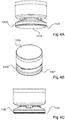
- FIGS. 4A-4C show various views of a mobile hands-free unit according to a fourth embodiment of the invention.
- the housing of the hands-free unit is shown. That in the FIGS. 4A-4C The housing shown is the same for the first and the second mobile hands-free unit 1100, 1200.
- the mobile hands-free unit 1100, 1200 has a bottom unit 1120 with a light unit 1121, for example in the form of a light ring.
- an accumulator 1010 may be provided on the ground unit 1120.
- a control unit 1110 may be provided on the upper side of the mobile hands-free unit 1100, 1200.
- the operating unit 1110 can be designed, for example, as a touchpad.
- the control unit 1110 may include a light unit 1111, a volume control 1112, a muting control 1130, and optionally a pairing control 1114.
- These may also have a bottom unit 1220 with a light ring 1221 and an accumulator 1010.
- Figs. 5A-5C show respectively different views of a loading and storage unit 2000 for the mobile hands-free units according to the invention.
- the loading and storage unit 2000 has a case 2100 with a carrying handle 2200.
- the case 2100 has a number of charging bays 2110 each having electrical charging contacts 2111. These electrical charging contacts 2111 can be represented for example by four electrically conductive and optionally spring-loaded pins 2111.
- the mobile hands-free units 1100, 1200 may be placed in the loading bays 2110 for storage and charging.
- the mobile hands-free units 1100, 1200 with their ground unit and the batteries 1010 placed therein are placed in the charging bays 2110 so that the charging pins 2111 are in electrical contact with the charging contacts of the battery unit.
- the electrical charging contacts 2111 serve not only to charge the accumulator unit 1010 of the mobile hands-free unit 1100, 1200, but also a data exchange between the mobile hands-free units 1100, 1200 and the storage and loading unit 2000. Thus, for example, data regarding the state of charge of the Ackumulatorü 1010 with the Storage and loading unit to be replaced. Furthermore, by means of the charging contacts both a charging of the accumulator unit and an energy flow in the other direction, namely from the accumulator unit to the loading and / or storage unit 2000 take place.
- the loading and / or storage unit 2000 has its own accumulator unit 2200. Furthermore, the charging and / or storage unit 2000 may have a control unit 2300 which controls a charging of the mobile hands-free units 1100, 1200 located in the charging bays 2110.
- loading and storage unit 2000 may further include a display unit 2400.
- the display unit 2400 may indicate the charging state of the mobile hands-free units 1100, 1200 located in the charging bays 2110.
- the operating time can be displayed via the display unit 2400 with which the mobile hands-free units can be operated on the basis of the current charging of the accumulator units 1010.
- the maximum conference duration can be displayed.
- the loading and storage unit is configured as a suitcase with a lid.
- the remaining running display according to the invention on the display unit 2400 can be determined by means of the control unit 2300.
- the control unit 2300 can detect the state of charge of the rechargeable batteries 1010 of the respective mobile hands-free units 1100, 1200 located in the charging slots 2110 and represent the corresponding maximum remaining time on the display unit 2400.
- the loading and storage unit 2000 has an operating unit 2500, by means of which, for example, the display of the remaining running time can be initiated.
- the control unit 2300 may, for example, have a charge control unit 2310 which detects the state of charge of the accumulators of the mobile hands-free units 1100, 1200 located in the charging shafts 2110, determines the charging state that is the lowest and accordingly indicates a remaining running time. In this case, the remaining time can be displayed, which allows complete operation of the conference system with all mobile hands-free units.
- the accumulator unit 2200 is optional. If this is not present, then the loading and storage unit 2000 can extract the energy required for the control unit 2300 from the accumulator units 1010 of the mobile hands-free units 1100, 1200 located in the charging slots 2110. Optionally, the energy required for the controller 2300 may be extracted from the accumulator unit 1010 having the highest state of charge.
- the charging contacts 2111 are designed so that an energy flow in both directions is possible.
- the accumulator units 1010 of the mobile hands-free units 1100, 1200 located in the charging slots 2110 are charged.
- the controller 2300 may then be powered by the external power source, i.
- the control unit 2300 is then not energized via the accumulator units 1010 located in the case.
- a display unit 1105 can also be activated in the operating unit 1110 when the remaining time display is activated.
- the remaining term of the respective mobile hands-free unit 1100, 1200 can then be displayed on this display unit 1105.
- the user can immediately with the charging case open the state of charge of the batteries of the mobile hands-free units 1100, 1200, which are placed in the charging slots 1110. This allows a user to select those mobile hands-free units that have the highest state of charge.
- the display unit 2400 may be provided on the outside of the loading and storage unit 2000, so that a user quickly and easily obtains information about the state of charge of the mobile hands-free units 1100, 1200 located in the loading and storage unit 2000. So he does not have to open the charging case.
- the first mobile hands-free unit 1100 is not placed in the loading and storage unit 2000, then this may be displayed via the display unit 2400.
- an optical warning may be provided in the form of flashing orange LEDs.
- the display unit 2400 may be displayed via the display unit 2400 when the loading slots 1110 are not fully occupied. This can for example be done so that the lowest Ackuladeschreib is displayed and this indicator flashes.
- the mobile hands-free units 1100, 1200 may be made round and have circular charging contacts at their bottom, so that the contacts can easily be placed on the charging pins 2111. In this case, exact rotational positioning is not important since the charging contacts 2111 always encounter an associated circular charging contact.
- the loading slots 2110 are preferably cylindrically configured so that they can accommodate at least the lower end or bottom unit of the mobile hands-free units 1100, 1200, respectively.
- the loading pins 2111 may be spring-loaded, for example.
- FIGS. 6A and 6B each show different views of another charging unit for the hands-free units according to the invention.
- a charging unit 3000 with 4 charging slots 3110 is provided for the hands-free units 1100, 1200.
- Charging contacts 3111 are provided in each charging slot 3110.
- These electrical charging contacts 3111 may represent, for example, four electrically conductive and optionally spring-loaded pins 3111.
- the mobile hands-free units 1100, 1200 may be placed in the loading bays 3110 for storage and charging.
- the mobile hands-free units 1100, 1200 with their ground unit and the batteries 1010 placed therein are placed in the charging bays 3110 so that the charging pins 3111 are in electrical contact with the charging contacts of the battery unit.
- the electric charging contacts 3111 serve not only to charge the battery unit 1010 of the mobile hands-free unit 1100, 1200, but also to exchange data between the mobile hands-free units 1100, 1200 and the charging unit 3000.
- data regarding the state of charge of the battery unit 1010 can be exchanged with the charging unit .
- both a charging of the accumulator unit and an energy flow in the other direction, namely from the accumulator unit to the loading and / or storage unit 3000 take place.
- the charging unit 3000 has its own accumulator unit 3200. Furthermore, the charging and / or storage unit 3000 may have a control unit 3300 which controls a charging of the mobile hands-free units 1100, 1200 located in the charging bays 3110.
- the charging unit 3000 may further include a display unit 3400.
- the display unit 3400 may indicate the charging state of the mobile hands-free units 1100, 1200 located in the charging bays 3110.
- the operating time can be displayed via the display unit 3400, with which the mobile hands-free units can be operated due to the current charging of the accumulator units 1010.
- the maximum conference duration can be displayed.
- the remaining running display according to the invention on the display unit 3400 can be determined by means of the control unit 3300.
- the control unit 3300 can detect the state of charge of the accumulators 1010 of the respective mobile hands-free units 1100, 1200 located in the charging slots 3110 and represent the corresponding maximum remaining time on the display unit 3400.
- the loading and storage unit 3000 has an operating unit 3500, by means of which, for example, the display of the remaining running time can be initiated.
- the control unit 3300 may, for example, have a charge control unit 3310, which detects the state of charge of the accumulators of the mobile hands-free units 1100, 1200 located in the charge slots 3110, determines the charge status that is lowest and accordingly indicates a residual maturity. In this case, the remaining time can be displayed, which allows complete operation of the conference system with all mobile hands-free units.
- the accumulator unit 3200 is optional. If this is not present, then the charging unit 3000 can extract the energy required for the control unit 3300 from the accumulator units 1010 of the mobile hands-free units 1100, 1200 located in the charging slots 3110. Optionally, the energy required for the control unit 3300 may be taken from the accumulator unit 1010 which has the highest state of charge.
- the charging contacts 3111 are designed so that an energy flow in both directions is possible.
- the accumulator units 1010 of the mobile hands-free units 1100, 1200 located in the charging slots 3110 are charged.
- the controller 3300 may then be powered by the external power source, i.
- the control unit 3300 is then not supplied with energy via the accumulator units 1010 located in the charging unit 3000.
- a display unit 1105 can also be activated in the operating unit 1110 when the remaining time display is activated.
- the remaining term of the respective mobile hands-free unit 1100, 1200 can then be displayed on this display unit 1105.
- the user can recognize the state of charge of the batteries of the mobile hands-free units 1100, 1200 placed in the charging slots 1110. This allows a user to select those mobile hands-free units that have the highest state of charge.
- the display unit 3400 may be provided on the outside of the charging unit 3000, so that a user obtains information about the state of charge of the mobile hands-free units 1100, 1200 located in the charging unit 3000 in a quick and simple manner.
- an optical warning may be provided in the form of flashing orange LEDs.
- the display unit 3400 may be displayed via the display unit 3400 when the loading slots 1110 are not fully occupied. This can for example be done so that the lowest Ackuladeschreib is displayed and this indicator flashes.
- the accumulator units 1010 can be designed round and have circular charging contacts, so that they can be easily placed on the charging pins 3111. In this case, exact positioning is not important since the charging contacts 3111 always encounter an associated circular charging contact.
- the loading slots 3110 are preferably cylindrically configured so that they can accommodate at least the lower end or bottom unit of the mobile hands-free units 1100, 1200, respectively.
- the loading pins 3111 may, for example, be spring-loaded.
- a mobile conferencing system having a plurality of mobile hands-free units.
- One of the hands-free mobile units acts as master while the other mobile hands-free units act as satellites or slaves.
- the master handsfree unit can also be considered as a central unit.
- the basic function of this central unit is to make an audio contact to at least one external communication partner and to reproduce the received audio signals and to output recorded audio signals to the external communication partner.
- the connection with an external communication partner can be made via a landline connection, a telephone connection or the like.
- the central unit or the master handsfree unit optionally does not itself produce the communication connection, but serves as an audio input / output unit, for example in the sense of a hands-free unit.
- the communication between the master handsfree unit and a telephone may, for example, be based on a Bluetooth connection. This connects the master handsfree unit to a mobile phone or smart phone like a Bluetooth headset.
- the mobile conference system further comprises at least one slave hands-free unit, which also has a microphone and a playback converter and is wirelessly connected to the master hands-free unit for bidirectional audio transmission.
- a master handsfree unit and three slave handsfree units may be provided in the mobile conference system. These are used for audio playback and audio recording in a good quality. For example, at a larger conference table the master handsfree unit and a number of slave handsfree units are optimally placed.
- the mobile conference system has a loading and storage unit for charging and storing or transporting the respective hands-free units. This makes the mobile conference system easy to transport and can be put into operation without major installation effort and without any wiring at a conference location. There is no infrastructure required, which would have to be installed at the conference site. Both the master handsfree unit and the slave handsfree units have an accumulator unit for the power supply. To put the mobile conference system into operation, only the first handsfree unit (master) and the second handsfree unit (slave) need to be placed on a conference table. A user can register the first handsfree unit (Master) on their smartphone or mobile phone as a headset for Bluetooth communication. Optionally, this can be done via an NFC near-field communications pairing.
- the user establishes a telephone connection via his smartphone to start a telephone conference.
- the audio signals received by the smartphone are reproduced by the loudspeakers of the first handsfree unit (master) as well as the loudspeakers of the second handsfree units (slaves).
- the audio signals detected by the microphones of the first hands-free unit as well as by the microphones of the second hands-free units are combined in the first hands-free unit and transmitted to the mobile telephone.
- the mobile conference system has a loading and storage unit in the form of a charging case, which is designed both for the transport and the charging of the batteries of the first and second mobile hands-free unit.
- the charging case can be connected to an external power source such as a power outlet to charge the mobile hands-free units.
- the mobile hands-free units can each be placed in a charging slot and charged accordingly.
- the charging contacts of the charging case and the electrical contacts of the accumulator units allow energy transfer in both directions and data transmission in both directions.
- the first mobile hands-free unit and the desired number of second mobile hands-free units are removed from the case and placed on the conference table.
- the mobile handsfree unit can be activated when removing it from the case.
- second mobile hands-free units may also be registered during operation of the mobile conferencing system and thus switched to the mobile conferencing system. This can be controlled by the control unit 1170 of the first hands-free unit 1100 and in particular by the slave synchronization unit 1175.
- the control unit 1170 of the first mobile hands-free unit 1100 can be removed from the charging case and placed on a conference table.
- the second mobile hands-free unit 1200 contacts the central unit via the wireless interface and logs in there.
- the control unit 1170 of the first mobile hands-free unit can activate the newly added second mobile hands-free unit without interrupting the conference.
- the second handsfree unit 1200 receives audio signals from the first handsfree unit and transmits audio signals to the first handsfree unit 1100. If a new second handsfree unit is to be added to the mobile conference, then the first handsfree unit must receive the audio signals from the new second handsfree unit and with the others Mix audio from the other second handsfree units together. Furthermore, the first hands-free unit must also distribute the audio signals received from the external unit to the new second hands-free unit. In addition, upon activation of the newly added second mobile hands-free unit 1200, an exchange of control signals between the first hands-free unit 1100 and the newly added second hands-free unit 1200 can take place in order to transmit a state of the entire system to the newly arrived second hands-free unit. For example, if the system is in the "muted" state, the newly registered second handsfree unit may assume and indicate this condition as well as the first handsfree unit.
- one of the second mobile hands-free units 1200 can be deactivated without interrupting the conference. This can be advantageous, for example, if the energy in the battery of one of the second mobile hands-free units is running out during the conference.
- the second mobile hands-free unit can then turn itself off, for example.
- the communication may be terminated when the second mobile hands-free unit is placed in the charging case. This can be detected, for example, by the storage and loading unit 2000 and transmitted to the first mobile hands-free unit. Alternatively, this can also be transmitted via the second mobile hands-free unit to the first mobile hands-free unit.
- both the first and second mobile hands-free units 1100, 1200 are provided with a lighting unit 1121, 1221.
- the first and second mobile handsfree unit or the mobile conference system can have different operating modes.
- a first mode may represent the connected mode (the connection between the master and the slaves is active)
- a second mode may represent the disconnected mode (there is no connection)
- a third mode may be a mute conference (the handsfree units are mute)
- a fourth mode may be a shared conference.
- These four modes of operation can be visualized by means of the light units 1121, 1221. In this case, different light colors and different light durations or flashing of the light can be used.
- the user can be given the appropriate operating mode, e.g. muted, of the mobile conferencing system.
- control signals can be exchanged, for example via the control interface 1190, between the first mobile hands-free unit and the second mobile hands-free units.
- the control unit 1170 and in particular the unit 1171 and the operation control unit 1176 and the lighting control unit 1177 can control both the operation mode and the control of the lighting units 1121, 1221.
- synchronous blinking of the lighting units 1121, 1221 may be provided. This can be done by means of the synchronous Blink unit 1171.
Landscapes
- Engineering & Computer Science (AREA)
- Signal Processing (AREA)
- Chemical & Material Sciences (AREA)
- Chemical Kinetics & Catalysis (AREA)
- Electrochemistry (AREA)
- General Chemical & Material Sciences (AREA)
- Multimedia (AREA)
- Computer Vision & Pattern Recognition (AREA)
- Life Sciences & Earth Sciences (AREA)
- Biophysics (AREA)
- Computer Hardware Design (AREA)
- Telephone Function (AREA)
Description
- Die vorliegende Erfindung betrifft ein mobiles Konferenzsystem.
- Herkömmliche Konferenzsysteme sind typischerweise fest verdrahtet und benötigen eine aufwendige Initialisierung. Derartige Konferenzsysteme sind somit beschränkt einsetzbar und können typischerweise nur von geschultem Personal initialisiert werden.
- Es ist eine Aufgabe der vorliegenden Erfindung ein mobiles Konferenzsystem vorzusehen, welches flexibel einsetzbar ist und ohne großen Aufwand initialisiert und gestartet werden kann.
- In der prioritätsbegründenden deutschen Patentanmeldung hat das Deutsche Patent- und Markenamt das folgende Dokument recherchiert:
US 2009/0264114 A1 . Weiterer Stand der Technik ist den DokumentenEP 2 755 368 ,US 2012/014534 A1 undUS 2013/316752 A1 zu entnehmen. - Diese Aufgabe wird durch ein Konferenzsystem nach Anspruch 1 gelöst.
- Es wird ein mobiles Konferenzsystem vorgesehen, das eine erste mobile Master-Freisprecheinheit und mindestens eine zweite mobile Slave-Freisprecheinheit aufweist, welche jeweils mindestens ein Mikrofon zur Aufzeichnung von Audiosignalen, einen Lautsprecher zur Wiedergabe von wiederzugebenen Audiosignalen, eine Akkumulatoreinheit zur Energieversorgung, eine Bedieneinheit, mindestens eine Leuchteinheit und eine erste Sende/Empfangseinheit zur bidirektionalen drahtlosen Kommunikation zwischen der ersten und zweiten mobilen Freisprecheinheit aufweisen. Die erste Freisprecheinheit weist eine zweite Sende/Empfangseinheit zur drahtlosen bidirektionalen Audio-Kommunikation mit einer externen Einheit auf. Die erste Freisprecheinheit ist dazu ausgestaltet, Audiosignale, welche über die zweite Sende-/Empfangseinheit von der externen Einheit empfangen wurden, durch die erste Sende/Empfangseinheit drahtlos an die zweite mobile Freisprecheinheit zu übertragen. Die erste Freisprecheinheit ist dazu ausgestaltet, Audiosignale, welche über die erste Sende-/Empfangseinheit von der zweiten mobilen Freisprecheinheit empfangen wurden mit über das mindestens eine Mikrofon der ersten Freisprecheinheit aufgezeichneten Audiosignalen zu mischen und durch die zweite Sende/Empfangseinheit drahtlos an die externe Einheit zu senden.
- Das erfindungsgemäße mobile Konferenzsystem weist eine erste mobile Freisprecheinheit (Master) und mindestens eine zweite mobile Freisprecheinheit (Slave) auf. Die erste mobile Freisprecheinheit weist eine Schnittstelle zur externen Kommunikation beispielsweise über ein Mobiltelefon oder über einen Festnetztelefonanschluss auf. Die erste mobile Freisprecheinheit (Master) weist eine zweite drahtlose Schnittstelle zur drahtlosen bidirektionalen Kommunikation mit der mindestens einen zweiten mobilen Freisprecheinheit (Slave) auf. Die zweite mobile Freisprecheinheit (Slave) weist (wie auch die erste mobile Freisprecheinheit optional) mindestens ein Mikrofon zur Aufzeichnung eines Audiosignals, mindestens einen Lautsprecher zur Wiedergabe eines wiederzugebenden Audiosignals, mindestens ein Bedienelement zum Bedienen der zweiten mobilen Freisprecheinheit, eine Steuereinheit zum Steuern der zweiten mobilen Freisprecheinheit und eine Drahtloskommunikationsschnittstelle zur bidirektionalen Kommunikation mit der ersten mobilen Freisprecheinheit. Die erste mobile Freisprecheinheit empfängt die von den Mikrofonen der zweiten mobilen Freisprecheinheiten aufgezeichneten Audiosignale, welche über die Drahtlosschnittstelle übertragen worden sind. Die erste mobile Freisprecheinheit empfängt ein externes Audiosignal über die externe Kommunikationsschnittstelle und überträgt dieses Audiosignal drahtlos an die mindestens eine mobile Freisprecheinheit, welche das Audiosignal oder zumindest Teile des Audiosignals über die Lautsprecher wiedergibt.
- Die erste mobile Freisprecheinheit und die zweite mobile Freisprecheinheit weist zumindest eine Leuchteinheit auf. Der Betrieb dieser Leuchteinheiten kann durch eine Steuereinheit der ersten mobilen Freisprecheinheit (Master) gesteuert werden. Insbesondere können die Leuchten in Abhängigkeit einer eingestellten Betriebsart zentral gesteuert werden.
- Gemäß einem weiteren Aspekt der vorliegenden Erfindung können durch Betätigung eines Muting-Bedienelementes alle Freisprecheinheiten gemutet werden. Dies kann durch die Leuchteinheiten entsprechend dargestellt werden. Dazu kann sich die Farbe der Leuchteinheit, die Intensität der Leuchteinheit und/oder das Blinken der Leuchteinheit verändern, sobald ein Muting der Freisprecheinheiten aktiviert ist.
- Gemäß einem weiteren Aspekt der vorliegenden Erfindung kann das Muting an jeder der Freisprecheinheiten aktiviert und/oder deaktiviert werden.
- Vorteile und Ausführungsbeispiele der Erfindung werden nachstehend unter Bezugnahme auf die Zeichnung näher erläutert.
- Fig. 1
- zeigt eine schematische Darstellung eines mobilen Konferenzsystems gemäß einem ersten Ausführungsbeispiel,
- Fig. 2
- zeigt ein Blockschaltbild einer ersten mobilen Freisprecheinheit gemäß einem zweiten Ausführungsbeispiel;
- Fig. 3
- zeigt ein Blockschaltbild einer zweiten mobilen Freisprecheinheit gemäß einem dritten Ausführungsbeispiel;
- Fig. 4A - Fig. 4C
- zeigen verschiedene Ansichten einer mobilen Freisprecheinheit gemäß einem vierten Ausführungsbeispiel der Erfindung;
- Fig. 5A-Fig. 5C
- zeigen jeweils verschiedene Ansichten einer Lade- und Aufbewahrungseinheit für die mobilen Freisprecheinheiten gemäß der Erfindung;
- Fig. 6A und 6B
- zeigen jeweils verschiedene Ansichten einer Ladeeinheit für die mobilen Freisprecheinheiten gemäß der Erfindung.
-
Fig. 1 zeigt eine schematische Darstellung eines mobilen Konferenzsystems gemäß einem ersten Ausführungsbeispiel. Das mobile Konferenzsystem 1000 weist eine erste mobile Freisprecheinheit (Master) 1100 und mindestens eine weitere bzw. zweite mobile Freisprecheinheit (Slave) 1200 auf. -
Fig. 2 zeigt ein Blockschaltbild einer ersten mobilen Freisprecheinheit gemäß einem zweiten Ausführungsbeispiel. Die erste mobile Freisprecheinheit (Master) 1100 weist eine Bedieneinheit 1110 mit einer ersten Leuchteinheit 1111, einem Lautstärkebedienelement 1112, einem Muting-Bedienelement 1113 und/oder einem Pairing-Bedienelement 1114 auf. Die erste mobile Freisprecheinheit 1100 weist eine Bodeneinheit 1120 mit einer zweiten Leuchteinheit 1121, mindestens einem Mikrofon 1130, mindestens einem Lautsprecher 1140, mindestens einer ersten Sende/Empfangseinheit 1150 auf. Die erste Sende-/Empfangseinheit 1150 kann eine drahtlose Schnittstelle beispielsweise basierend auf dem DECT-Standard darstellen und dient der Kommunikation zwischen der ersten mobilen Freisprecheinheit (Master) 1100 und den zweiten mobilen Freisprecheinheiten (Slave) 1200. Die erste mobile Freisprecheinheit (Master) weist ferner eine zweite Sende/Empfangseinheit 1160 bzw. eine zweite Drahtloskommunikationsschnittstelle 1160 auf. Die zweite Sende-/Empfangseinheit 1160 kann eine Drahtlossende/Empfangseinheit 1161 beispielsweise basierend auf dem WiFi-Protokoll oder dem Bluetooth-Protokoll und/oder eine drahtgebundene Sende/Empfangseinheit 1162, beispielsweise basierend auf einem USB-Anschluss, einem AUX-Anschluss, einem Festnetzanschluss etc. aufweisen. Die zweite Sende/Empfangseinheit 1160 dient zur bidirektionalen Übertragung von Audiosignalen zwischen dem Konferenzsystem 1000 und einer externen Fernkommunikationseinheitwie z.B. einem Smartphone. - Die erste mobile Freisprecheinheit 1100 weist ferner eine Steuereinheit 1170 zum Steuern des Betriebs der ersten und zweiten Freisprecheinheiten 1100, 1200 auf. Die Steuereinheit 1170 kann eine erste Leuchtsteuereinheit 1171 zum Steuern der Leuchteinheiten der ersten und/oder zweiten mobilen Freisprecheinheit, eine Pairing-Einheit 1172 zur Initialisierung und/oder Steuerung eines Pairings zwischen einem Mobiltelefon und der ersten mobilen Freisprecheinheit. Die Steuereinheit 1170 kann ferner eine Lautstärkesteuereinheit 1173, eine Bedienelementsteuereinheit 1174, eine Slave-Synchronisationseinheit 1175, eine Betriebsartsteuereinheit 1176 und/oder eine zweite Leuchtensteuereinheit 1177 aufweisen.
- Die erste mobile Freisprecheinheit 1100 weist eine Audio-Mischeinheit 1180 mit einer ersten Audioaktivitätserfassungseinheit 1181 zum Erfassen einer Audioaktivität über die interne Schnittstelle 1150 zur Kommunikation mit den zweiten mobilen Freisprecheinheiten 1200 sowie eine zweite Audioaktivitätserfassungseinheit 1182 zum Erfassen einer Audioaktivität über die externe Schnittstelle 1160.
- Die erste mobile Freisprecheinheit 1100 weist eine Steuerschnittstelle 1190 zur drahtlosen, bidirektionalen Kommunikation von Steuersignalen, insbesondere an die mindestens eine zweite mobile Freisprecheinheit 1200 auf. Die Steuerschnittstelle 1190 kann eine I2S-Einheit 1191 und eine Slave-Steuereinheit 1192 aufweisen. Optional können die Steuersignale in die Audiodaten eingebettet sein und somit kann die erste mobile Freisprecheinheit (Master) 1100 über ihre Sende/Empfangseinheit 1150 Steuersignale an die zweiten mobilen Freisprecheinheiten (Slave) 1200 senden und von diesen empfangen. In diesem Fall ist die Steuerschnittstelle 1190 der ersten mobilen Freisprecheinheit 1100 also in die erste Sende-/Empfangseinheit 1150 integriert.
- Ferner weist die erste mobile Freisprecheinheit 1100 eine Akkumulatoreinheit 1010 auf, aus welcher die Freisprecheinheit 1100 mobil mit elektrischer Energie versorgt werden kann.
-
Fig. 3 zeigt ein Blockschaltbild einer zweiten mobilen Freisprecheinheit gemäß einem dritten Ausführungsbeispiel. Die zweite mobile Freisprecheinheit 1200, welche als Slave ausgestaltet ist, weist eine Bedieneinheit 1210 mit einer ersten Leuchteinheit 1211, einem Lautstärkebedienelement 1212 und/oder einem Muting-Bedienelement 1213 auf. Ferner weist die zweite mobile Freisprecheinheit 1200 eine Bodeneinheit 1220 mit einer Leuchteinheit 1221, mindestens ein Mikrofon 1230, mindestens einen Lautsprecher 1240, mindestens eine Sende/Empfangseinheit bzw. eine drahtlose Schnittstelleneinheit 1250 und/oder eine Steuereinheit 1270 auf. Über die Sende/Empfangseinheit 1250 können die über das Mikrofon 1230 erfassten Audiosignale an die erste mobile Freisprecheinheit 1100 drahtlos übermittelt werden. Über die Sende/Empfangseinheit 1250 können wiederzugebende Audiosignale von der ersten mobilen Freisprecheinheit 1100 drahtlos empfangen werden und über den mindestens einen Lautsprecher 1240 wiedergegeben werden. Über die Sende/Empfangseinheit 1250 bzw. über eine entsprechende Untereinheit wie beispielsweise eine Steuersignalempfangseinheit 1251 können Steuersignale von der ersten mobilen Freisprecheinheit 1100 empfangen werden. Diese Signale können dann mittels der Steuereinheit 1270 umgesetzt werden. Beispielsweise kann die Leuchteinheit 1211 und/oder die Leuchteinheit 1221 (z.B. beim Muting der Freisprecheinheiten) aktiviert bzw. ein- und ausgeschaltet werden. Da die Steuerung des Ein- und Ausschaltens der Leuchteinheiten 1211 und 1221 der zweiten mobilen Freisprecheinheiten von der Steuereinheit 1170 der ersten mobilen Freisprecheinheit (Master) 1100 kommt, können die zweiten mobilen Freisprecheinheiten (Slaves) entsprechend der Betriebsart beispielsweise synchron mit der ersten mobilen Freisprecheinheit (Master) 1100 blinken. - Auch die zweite mobile Freisprecheinheit 1200 weist eine Akkumulatoreinheit 1010 auf, aus welcher die Freisprecheinheit 1200 mobil mit elektrischer Energie versorgt werden kann. Optional weist die zweite mobile Freisprecheinheit 1200 eine Steuerschnittstelle 1290 zur drahtlosen, bidirektionalen Kommunikation von Steuersignalen, insbesondere mit der ersten mobilen Freisprecheinheit 1100 auf. Optional können die Steuersignale in die Audiodaten eingebettet sein und somit dient die Sende-/Empfangseinheit 1250 der zweiten mobilen Freisprecheinheit (Slave) 1200 gleichzeitig als Steuerschnittstelle 1290.
- Gemäß einem Aspekt der vorliegenden Erfindung kann eine gemeinsame Mute-Funktion für das gesamte Konferenzsystem 1000 bestehend aus einer ersten mobilen Freisprecheinheit (Master) 1100 und mindestens einer zweiten mobilen Freisprecheinheiten (Slave) 1200 vorgesehen sein. Die Mute-Funktion wird hierbei so umgesetzt, dass in einem Zustand "muted" keines der von dem Konferenzsystem 1000 erfassten Mikrofonsignale an die über die zweite Sende-/Empfangseinheit 1160 angeschlossene externe Kommunikationseinheit ausgegeben wird. Die Mastereinheit 1100 enthält das Muting-Bedienelement 1113 und jede Slave-Einheit 1200 ein Muting-Bedienelement 1213. Wird ein Muting-Bedienelement 1213 einer Slave-Einheit 1200 betätigt, so überträgt die Slave-Einheit diese Information in Form eines Muting-Steuerbefehls über die Steuerschnittstelle 1290 der Slave-Einheit an die Steuerschnittstelle 1190 der Master-Einheit. Die Master-Einheit 1100 setzt die Mute-Funktion um, indem sie die Ausgabe von Audiosignalen an die zweite Sende-/Empfangseinheit 1160 der Master-Einheit 1100 unterbricht und somit die Ausgabe von Audiosignalen an die externe Kommunikationseinheit für das gesamte Konferenzsystem 1000 unterbricht. Wird stattdessen das Muting-Bedienelement 1113 der Master-Einheit 1100 betätigt, so kann die Master-Einheit die Mute-Funktion für das gesamte Konferenzsystem 1000 intern umsetzen, indem sie die Ausgabe von Audiosignalen an die zweite Sende-/Empfangseinheit 1160 der Master-Einheit 1100 unterbricht. In beiden Fällen kann die Master-Einheit optional zusätzlich einen entsprechenden Steuerbefehl an alle verbundenen Slave-Einheiten 1200 aussenden, um den neuen Zustand "muted" zu melden. Dieser Zustand kann dann sowohl an der Master-Einheit 1100 über die zugehörige Leuchteinheit 1111 als auch an allen verbundenen Slave-Einheiten 1200 über zugehörige Leuchteinheiten 1211 gleichermaßen angezeigt werden. Die Deaktivierung der Mute-Funktion kann entsprechend der Aktivierung der Mute-Funktion erfolgen. Es kann also wahlweise das Muting-Bedienelement 1113 der Master-Einheit 1100 oder ein Muting-Bedienelement 1213 einer verbundenen Slave-Einheit 1200 betätigt werden und ggf. durch Übertragung entsprechender Steuerbefehle wird die Mastereinheit die Audioausgabe an die zweite Sende-/Empfangseinheit 1160 der Master-Einheit 1100 wieder aktivieren. Der dann erzeugte Zustand "unmuted" kann wieder durch Übertragung entsprechender Steuerbefehle sowohl an der Master-Einheit 1100 über die zugehörige Leuchteinheit 1111 als auch an allen verbundenen Slave-Einheiten 1200 über zugehörige Leuchteinheiten 1211 gelichermaßen angezeigt werden. Es ist also möglich, das ganze Konferenzsystem 1000 über ein beliebiges der beteiligten Muting-Bedienelemente 1113 oder 1213 in den Zustand "muted" zu versetzen und später ggf. über ein anderes der beteiligten Muting-Bedienelemente wieder in den Zustand "unmuted" zu versetzen.
- Die Bedieneinheit 1110, 1210 der ersten und zweiten mobilen Freisprecheinheit 1100, 1200 kann beispielsweise zumindest teilweise als ein Touchpad ausgestaltet sein. Wenn beispielsweise ein Anwender das Pairing-Bedienelement 1114 betätigt und beispielsweise sein Mobiltelefon auf die Bedieneinheit 1110 ablegt, dann kann beispielsweise mittels der Bedienelementsteuereinheit 1174 der Steuereinheit 1170 der ersten mobilen Freisprecheinheit 1100 die Bedieneinheit bzw. einige Bedienelemente deaktiviert werden, so lange das Mobiltelefon auf der Bedieneinheit 1110 platziert ist. Hierdurch soll vermieden werden, dass die Bedienelemente 1112, 1113 unbeabsichtigt betätigt werden.
- Insbesondere enthält die Zentraleinheit 1100 eine Bedieneinheit 1110, über die der Benutzer ihre Funktionen steuern kann. Beispielsweise kann die Lautstärke der Audiowiedergabe erhöht oder verringert werden oder eine Mute-Funktion für das an das externe Fernkommunikationsgerät auszugebene Mikrofonsignal vorgesehen sein. Für eine komfortable Bedienung ist die Bedieneinheit 1110 vorzugsweise auf der Oberseite der Zentraleinheit 1100 vorgesehen (siehe
Fig. 1 ), optional in Form eines Touchpads. Zusätzlich kann die Oberseite der Zentraleinheit 1100 dazu vorgesehen sein, z.B. ein Smartphone darauf zu legen, um z.B. ein Bluetooth-Pairing über NFC (near field communication) durchzuführen. In diesem Falle wird also das Smartphone auf die Bedieneinheit 1110 der Zentraleinheit 1100 gelegt. Um ungewollte Betätigungen der Bedieneinheit zu verhindern, kann eine automatische Deaktivierung der Bedieneinheit 1110 vorgesehen werden, die solange anhält, wie sich das Smartphone in der NFC-Reichweite (wenige Zentimeter) der Zentraleinheit befindet. - Zum Pairing eines Mobiltelefons mit der ersten mobilen Freisprecheinheit 1100 kann ein Pairing-Bedienelement 1114 betätigt werden. Anschließend kann beispielsweise das zu paarende Mobiltelefon auf die Bedieneinheit 1110 platziert werden. Die Betätigung des Pairing-Bedienelements 1114 kann optional über NFC (nearfield communication) erfolgen. In diesem Falle wird das Mobiltelefon auf die Bedieneinheit 1110 platziert und durch die räumliche Annäherung des Mobiltelefons zu der ersten mobilen Freisprecheinheit 1100 wird eine automatische Betätigung des Pairing-Bedienelements 1114 eingeleitet. Bei Betätigen des Pairing-Bedienelementes 1114 kann eine Pairingeinheit 1172 aktiviert werden. Ferner kann eine Bedienelementsteuereinheit 1174 aktiviert werden, welche das Touchpad 1110 während des Pairingvorganges deaktivieren kann, so dass damit verhindert werden kann, dass durch ein Platzieren eines Mobiltelefones auf die Bedieneinheit 1110 es zu einer versehentlichen Aktivierung einer der Bedienelemente kommt.
- Gemäß einem Aspekt der vorliegenden Erfindung kann die erste und/oder zweite mobile Freisprecheinheit 1100, 1200 jeweils einen USB-Anschluss 1101, 1201 in Form einer USB-Buchse aufweisen, über welche die mobile Freisprecheinheit mit Energie versorgt werden kann. Damit kann die mobile Freisprecheinheit betrieben werden, wenn die Akkumulatoreinheit 1010 leer ist.
- Gemäß einem Aspekt der vorliegenden Erfindung weist die erste und/oder zweite mobile Freisprecheinheit 1100, 1200 mindestens zwei Mikrofone 1130, 1131, 1230, 1231 auf. Hierbei können jeweils die ersten Mikrofone 1130, 1230 zur Erfassung eines Nutzaudiosignals verwendet werden, während beispielsweise die zweiten Mikrofone 1131, 1231 jeweils zur Erfassung von Lärm bzw. Störaudiosignalen verwendet werden. Mittels dieser erfassten Störaudiosignale kann eine Störreduzierung in den mobilen Freisprecheinheiten 1100, 1200 erreicht werden. Optional können die mobilen Freisprecheinheiten Mikrofon-Arrays mit einer Mehrzahl von Mikrofonen aufweisen, deren Richtcharakteristik optional dynamisch anpassbar ist.
- Gemäß der Erfindung kann die erste mobile Freisprecheinheit (Master) 1100 über die zweite Drahtlosschnittstelle 1160 mehrere Audiosignale auf mehreren Kanälen empfangen. Beispielsweise können verschiedene Teilnehmer jeweils einem eigenen Kanal zugeordnet werden. Optional können dann die empfangenen (unterschiedlichen) Audiokanäle über unterschiedliche zweite mobile Freisprecheinheiten (Slave) 1200 wiedergegeben werden. Somit kann beispielsweise ein Teilnehmer bzw. das Audiosignal von ihm über eine der zweiten mobilen Freisprecheinheiten 1200 und ein anderer Teilnehmer über eine andere mobile Freisprecheinheit 1200 wiedergegeben werden. Optional kann die Lautstärke variiert bzw. angepasst werden. Dies kann insbesondere erfolgen, damit die Teilnehmer erkennen können, aus welcher Audioquelle gesprochen wird. Wenn mehr Kanäle als zweite mobile Freisprecheinheiten (Slave-Wiedergabegeräte) 1200 vorgesehen sind, dann können einzelne Kanäle auf die vorhandenen mobilen Freisprecheinheiten über verschiedene Lautstärken auf den einzelnen Freisprecheinheiten im Sinne einer Balance-Regelung verteilt werden.
- Wenn somit die erste mobile Freisprecheinheit 1100 ein mehrkanaliges Audioeingangssignal von einer externen Audioquelle über die zweite Drahtlosschnittstelle 1160 empfängt, können die jeweiligen Audiokanäle über einzelne zweite mobile Freisprecheinheiten 1200 wiedergegeben werden. Alternativ dazu können mehrere Kanäle über die zweiten mobilen Freisprecheinheiten 1200 wiedergegeben werden.
- Eine zweite Kommunikationsschnittstelle 1160 der ersten mobilen Freisprecheinheit 1100 kann beispielsweise mit einer Voice-Over-IP-Schnittstelle gekoppelt werden. Damit können beispielsweise die Teilnehmer einer Konferenz über eine Voice-Over-IP-Schnittstelle mit der Konferenz verbunden werden. Optional kann mittels der Leuchteinheiten der mobilen Freisprecheinheiten auch ein optisches Feedback erzeugt werden, wenn ein Audiosignal auf dem Audiokanal empfangen wird, welcher durch eine der zweiten mobilen Freisprecheinheiten 1200 wiedergegeben wird.
- Gemäß einem Aspekt der vorliegenden Erfindung kann die erste mobile Freisprecheinheit 1100 über die Audiomischeinheit 1180 die von den zweiten mobilen Freisprecheinheiten 1200 empfangen Audiosignale zusammenmischen und dann als ein Gesamtaudiosignal ausgeben oder es kann die empfangenen Audiosignale auf verschiedene Audiokanäle aufteilen und die jeweiligen Audiokanäle ausgeben. So kann beispielsweise ein Audiokanal pro zweite mobile Freisprecheinheit 1200 vorgesehen sein. Damit kann beispielsweise bei anderen Teilnehmern der Konferenz, welche sich nicht im selben Raum befinden, aber beispielsweise dasselbe System benutzen, eine audiokanalspezifische Wiedergabe erfolgen. Damit kann beispielsweise ein akustischer Eindruck der Sitzordnung der Konferenzteilnehmer, welche die erste und mindestens eine zweite mobile Freisprecheinheit verwenden, nachgebildet werden.
- Optional kann die Information, um welchen Audiokanal es sich handelt und damit wer gerade spricht, an die externen Teilnehmer der Konferenz ausgegeben werden.
-
Fig. 4A - Fig. 4C zeigen verschiedene Ansichten einer mobilen Freisprecheinheit gemäß einem vierten Ausführungsbeispiel der Erfindung. In denFiguren 4A- 4C ist insbesondere das Gehäuse der Freisprecheinheit dargestellt. Das in denFiguren 4A - 4C dargestellte Gehäuse ist dasselbe für die erste als auch die zweite mobile Freisprecheinheit 1100, 1200. Die mobile Freisprecheinheit 1100, 1200 weist eine Bodeneinheit 1120 mit einer Leuchteinheit 1121 beispielsweise in Form eines Leuchtringes auf. In oder an der Bodeneinheit 1120 kann ein Akkumulator 1010 vorgesehen sein. Auf der Oberseite der mobilen Freisprecheinheit 1100, 1200 kann eine Bedieneinheit 1110 vorgesehen sein. Die Bedieneinheit 1110 kann beispielsweise als Touchpad ausgestaltet sein. Die Bedieneinheit 1110 kann eine Leuchteinheit 1111, eine Bedienelement für die Lautstärke 1112, ein Bedienelement für ein Muting 1130 sowie optional ein Bedienelement zum Pairing 1114 aufweisen. - Entsprechendes gilt für die zweite mobile Freisprecheinheit 1200. Auch diese kann eine Bodeneinheit 1220 mit einem Leuchtring 1221 und einem Akkumulator 1010 aufweisen.
-
Fig. 5A-5C zeigen jeweils verschiedene Ansichten einer Lade- und Aufbewahrungseinheit 2000 für die mobilen Freisprecheinheiten gemäß der Erfindung. Die Lade- und Aufbewahrungseinheit 2000 weist einen Koffer 2100 mit einem Tragegriff 2200 auf. Der Koffer 2100 weist eine Anzahl von Ladebuchten 2110 auf, welche jeweils elektrische Ladekontakte 2111 aufweisen. Diese elektrischen Ladekontakte 2111 können beispielsweise durch vier elektrisch leitfähige und optional gefederte Pins 2111 dargestellt werden. Die mobilen Freisprecheinheiten 1100, 1200 können zur Aufbewahrung und Aufladung in die Ladebuchten 2110 platziert werden. Insbesondere werden die mobilen Freisprecheinheiten 1100, 1200 mit ihrer Bodeneinheit sowie den darin platzierten Akkus 1010 in die Ladebuchten 2110 platziert, so dass die Ladepins 2111 im elektrischen Kontakt stehen mit den Ladekontakten der Akkumulatoreinheit. - Die elektrischen Ladekontakte 2111 dienen nicht nur zum Aufladen der Akkumulatoreinheit 1010 der mobilen Freisprecheinheit 1100, 1200, sondern auch einem Datenaustausch zwischen den mobilen Freisprecheinheiten 1100, 1200 sowie der Aufbewahrungs- und Ladeeinheit 2000. Somit können beispielsweise Daten hinsichtlich des Ladezustandes der Ackumulatoreinheit 1010 mit der Aufbewahrungs- und Ladeeinheit ausgetauscht werden. Ferner kann mittels der Ladekontakte sowohl eine Aufladung der Akkumulatoreinheit als auch ein Energiefluss in die andere Richtung, nämlich von der Akkumulatoreinheit zu der Lade- und/oder Aufbewahrungseinheit 2000 erfolgen.
- Optional weist die Lade- und/oder Aufbewahrungseinheit 2000 eine eigene Akkumulatoreinheit 2200 auf. Desweiteren kann die Lade- und/oder Aufbewahrungseinheit 2000 eine Steuereinheit 2300 aufweisen, welche eine Aufladung der sich in den Ladebuchten 2110 befindlichen mobilen Freisprecheinheiten 1100, 1200 steuert.
- Optional können Lade- und Aufbewahrungseinheit 2000 ferner eine Anzeigeeinheit 2400 aufweisen. Die Anzeigeeinheit 2400 kann den Aufladezustand der sich in den Ladebuchten 2110 befindlichen mobilen Freisprecheinheiten 1100, 1200 anzeigen. Insbesondere kann über die Anzeigeeinheit 2400 diejenige Betriebszeit dargestellt werden, mit welcher die mobilen Freisprecheinheiten aufgrund der aktuellen Aufladung der Akkumulatoreinheiten 1010 betrieben werden kann. Damit kann somit die maximale Konferenzdauer angezeigt werden.
- Gemäß einem Aspekt der vorliegenden Erfindung ist die Lade- und Aufbewahrungseinheit als ein Koffer mit einem Deckel ausgestaltet.
- Die erfindungsgemäße Restlaufanzeige auf der Anzeigeeinheit 2400 kann mittels der Steuereinheit 2300 ermittelt werden. Dazu kann die Steuereinheit 2300 den Ladezustand der Akkumulatoren 1010 der jeweiligen sich in den Ladeschächten 2110 befindlichen mobilen Freisprecheinheiten 1100, 1200 erfassen und die entsprechende maximale Restlaufzeit auf der Anzeigeeinheit 2400 darstellen. Die Lade- und Aufbewahrungseinheit 2000 weist eine Bedieneinheit 2500 auf, mittels welcher beispielsweise die Anzeige der Restlaufzeit initiiert werden kann.
- Die Steuereinheit 2300 kann beispielsweise eine Ladekontrolleinheit 2310 aufweisen, welche den Ladezustand der Akkumulatoren der sich in den Ladeschächten 2110 befindlichen mobilen Freisprecheinheiten 1100, 1200 erfasst, denjenigen Ladezustand bestimmt, der am geringsten ist und entsprechend eine Restlaufzeit anzeigt. Hierbei kann diejenige Restlaufzeit angezeigt werden, welche einen vollständigen Betrieb des Konferenzsystems mit allen mobilen Freisprecheinheiten ermöglicht. Die Akkumulatoreinheit 2200 ist optional. Falls diese nicht vorhanden ist, dann kann die Lade- und Aufbewahrungseinheit 2000 die für die Steuereinheit 2300 benötigte Energie aus den Akkumulatoreinheiten 1010 der sich in den Ladeschächten 2110 befindlichen mobilen Freisprecheinheiten 1100, 1200 extrahieren. Optional kann die für die Steuereinheit 2300 benötigte Energie von derjenigen Ackumulatoreinheit 1010 entnommen werden, welche über den höchsten Ladezustand verfügt.
- Die Ladekontakte 2111 sind so ausgelegt, dass ein Energiefluss in beide Richtungen möglich ist.
- Wenn der Ladekoffer bzw. die Lade- und Aufbewahrungseinheit 2000 an eine externe Energiequelle angeschlossen wird, beispielsweise an das Energieversorgungsnetz mittels einer Steckdose, dann werden die Akkumulatoreinheiten 1010 der sich in den Ladeschächten 2110 befindlichen mobilen Freisprecheinheiten 1100, 1200 geladen. Optional kann die Steuereinheit 2300 dann über die externe Energiequelle mit Energie versorgt werden, d.h. optional wird die Steuereinheit 2300 dann nicht über die sich in dem Koffer befindlichen Akkumulatoreinheiten 1010 mit Energie versorgt.
- Gemäß der Erfindung kann bei Aktivierung der Restlaufzeitanzeige auch eine Anzeigeeinheit 1105 in der Bedieneinheit 1110 aktiviert werden. Auf dieser Anzeigeeinheit 1105 kann dann die Restlaufzeit der jeweiligen mobilen Freisprecheinheit 1100, 1200 angezeigt werden. Somit kann der Nutzer bei geöffnetem Ladekoffer sofort den Ladezustand der Akkumulatoren der mobilen Freisprecheinheiten 1100, 1200 erkennen, welche in den Ladeschächten 1110 platziert sind. Damit kann ein Anwender diejenigen mobilen Freisprecheinheiten auswählen, welche über den höchsten Ladezustand verfügen.
- Die Anzeigeeinheit 2400 kann außen an der Lade- und Aufbewahrungseinheit 2000 vorgesehen sein, so dass ein Anwender auf schnelle und einfache Art und Weise Informationen über den Ladezustand der sich in der Lade- und Aufbewahrungseinheit 2000 befindlichen mobilen Freisprecheinheiten 1100, 1200 erhält. Dazu muss er also den Ladekoffer nicht öffnen.
- Falls die erste mobile Freisprecheinheit 1100 nicht in der Lade- und Aufbewahrungseinheit 2000 platziert ist, dann kann dies über die Anzeigeeinheit 2400 dargestellt werden. Beispielsweise kann eine optische Warnung in Form von blinkenden orangenen LEDs vorgesehen sein.
- Optional kann über die Anzeigeeinheit 2400 dargestellt werden, wenn die Ladeschächte 1110 nicht voll besetzt sind. Dies kann beispielsweise so erfolgen, dass der niedrigste Ackuladezustand angezeigt wird und diese Anzeige blinkt.
- Gemäß der Erfindung können die mobilen Freisprecheinheiten 1100, 1200 rund ausgestaltet sein und an ihrem Boden über kreisförmige Ladekontakte verfügen, so dass die Kontakte ohne weiteres auf die Ladepins 2111 platziert werden können. Hierbei kommt es dann nicht auf eine exakte rotatorische Positionierung an, da die Ladekontakte 2111 immer auf einen zugehörigen kreisförmigen Ladekontakt treffen.
- Optional sind die Ladeschächte 2110 vorzugsweise zylindrisch ausgestaltet, so dass sie zumindest das untere Ende bzw. die Bodeneinheit der mobilen Freisprecheinheiten 1100, 1200 aufnehmen können. Die Ladepins 2111 können beispielsweise federgelagert sein.
-
Fig. 6A und 6B zeigen jeweils verschiedene Ansichten einer weiteren Ladeeinheit für die Freisprecheinheiten gemäß der Erfindung. InFig. 6A und 6B ist eine Ladeeinheit 3000 mit 4 Ladeschächten 3110 für die Freisprecheinheiten 1100, 1200 vorgesehen. In jedem Ladeschacht 3110 sind Ladekontakte 3111 vorgesehen. - Diese elektrischen Ladekontakte 3111 können beispielsweise durch vier elektrisch leitfähige und optional gefederte Pins 3111 darstellen. Die mobilen Freisprecheinheiten 1100, 1200 können zur Aufbewahrung und Aufladung in die Ladebuchten 3110 platziert werden.
- Insbesondere werden die mobilen Freisprecheinheiten 1100, 1200 mit ihrer Bodeneinheit sowie den darin platzierten Akkus 1010 in die Ladebuchten 3110 platziert, so dass die Ladepins 3111 im elektrischen Kontakt stehen mit den Ladekontakten der Akkumulatoreinheit.
- Die elektrischen Ladekontakte 3111 dienen nicht nur zum Aufladen der Akkumulatoreinheit 1010 der mobilen Freisprecheinheit 1100, 1200, sondern auch einem Datenaustausch zwischen den mobilen Freisprecheinheiten 1100, 1200 sowie der Ladeeinheit 3000. Somit können beispielsweise Daten hinsichtlich des Ladezustandes der Akkumulatoreinheit 1010 mit der Ladeeinheit ausgetauscht werden. Ferner kann mittels der Ladekontakte sowohl eine Aufladung der Akkumulatoreinheit als auch ein Energiefluss in die andere Richtung, nämlich von der Akkumulatoreinheit zu der Lade- und/oder Aufbewahrungseinheit 3000 erfolgen.
- Optional weist die Ladeeinheit 3000 eine eigene Akkumulatoreinheit 3200 auf. Desweiteren kann die Lade- und/oder Aufbewahrungseinheit 3000 eine Steuereinheit 3300 aufweisen, welche eine Aufladung der sich in den Ladebuchten 3110 befindlichen mobilen Freisprecheinheiten 1100, 1200 steuert.
- Optional kann die Ladeeinheit 3000 ferner eine Anzeigeeinheit 3400 aufweisen. Die Anzeigeeinheit 3400 kann den Aufladezustand der sich in den Ladebuchten 3110 befindlichen mobilen Freisprecheinheiten 1100, 1200 anzeigen. Insbesondere kann über die Anzeigeeinheit 3400 diejenige Betriebszeit dargestellt werden, mit welcher die mobilen Freisprecheinheiten aufgrund der aktuellen Aufladung der Akkumulatoreinheiten 1010 betrieben werden kann. Damit kann somit die maximale Konferenzdauer angezeigt dauer.
- Die erfindungsgemäße Restlaufanzeige auf der Anzeigeeinheit 3400 kann mittels der Steuereinheit 3300 ermittelt werden. Dazu kann die Steuereinheit 3300 den Ladezustand der Akkumulatoren 1010 der jeweiligen sich in den Ladeschächten 3110 befindlichen mobilen Freisprecheinheiten 1100, 1200 erfassen und die entsprechende maximale Restlaufzeit auf der Anzeigeeinheit 3400 darstellen. Die Lade- und Aufbewahrungseinheit 3000 weist eine Bedieneinheit 3500 auf, mittels welcher beispielsweise die Anzeige der Restlaufzeit initiiert werden kann.
- Die Steuereinheit 3300 kann beispielsweise eine Ladekontrolleinheit 3310 aufweisen, welche den Ladezustand der Akkumulatoren der sich in den Ladeschächten 3110 befindlichen mobilen Freisprecheinheiten 1100, 1200 erfasst, denjenigen Ladezustand bestimmt, der am geringsten ist und entsprechend eine Restlaufzeit anzeigt. Hierbei kann diejenige Restlaufzeit angezeigt werden, welche einen vollständigen Betrieb des Konferenzsystems mit allen mobilen Freisprecheinheiten ermöglicht. Die Akkumulatoreinheit 3200 ist optional. Falls diese nicht vorhanden ist, dann kann die Ladeeinheit 3000 die für die Steuereinheit 3300 benötigte Energie aus den Akkumulatoreinheiten 1010 der sich in den Ladeschächten 3110 befindlichen mobilen Freisprecheinheiten 1100, 1200 extrahieren. Optional kann die für die Steuereinheit 3300 benötigte Energie von derjenigen Akkumulatoreinheit 1010 entnommen werden, welche über den höchsten Ladezustand verfügt.
- Die Ladekontakte 3111 sind so ausgelegt, dass ein Energiefluss in beide Richtungen möglich ist.
- Wenn die Ladeeinheit 3000 an eine externe Energiequelle angeschlossen wird, beispielsweise an das Energieversorgungsnetz mittels einer Steckdose, dann werden die Akkumulatoreinheiten 1010 der sich in den Ladeschächten 3110 befindlichen mobilen Freisprecheinheiten 1100, 1200 geladen. Optional kann die Steuereinheit 3300 dann über die externe Energiequelle mit Energie versorgt werden, d.h. optional wird die Steuereinheit 3300 dann nicht über die sich in der Ladeeinheit 3000 befindlichen Akkumulatoreinheiten 1010 mit Energie versorgt.
- Gemäß der Erfindung kann bei Aktivierung der Restlaufzeitanzeige auch eine Anzeigeeinheit 1105 in der Bedieneinheit 1110 aktiviert werden. Auf dieser Anzeigeeinheit 1105 kann dann die Restlaufzeit der jeweiligen mobilen Freisprecheinheit 1100, 1200 angezeigt werden. Somit kann der Nutzer den Ladezustand der Akkumulatoren der mobilen Freisprecheinheiten 1100, 1200 erkennen, welche in den Ladeschächten 1110 platziert sind. Damit kann ein Anwender diejenigen mobilen Freisprecheinheiten auswählen, welche über den höchsten Ladezustand verfügen.
- Die Anzeigeeinheit 3400 kann außen an der Ladeeinheit 3000 vorgesehen sein, so dass ein Anwender auf schnelle und einfache Art und Weise Informationen über den Ladezustand der sich in der Ladeeinheit 3000 befindlichen mobilen Freisprecheinheiten 1100, 1200 erhält.
- Falls die erste mobile Freisprecheinheit 1100 nicht in Ladeeinheit 3000 platziert ist, dann kann dies über die Anzeigeeinheit 3400 dargestellt werden. Beispielsweise kann eine optische Warnung in Form von blinkenden orangenen LEDs vorgesehen sein.
- Optional kann über die Anzeigeeinheit 3400 dargestellt werden, wenn die Ladeschächte 1110 nicht voll besetzt sind. Dies kann beispielsweise so erfolgen, dass der niedrigste Ackuladezustand angezeigt wird und diese Anzeige blinkt.
- Gemäß der Erfindung können die Akkumulatoreinheiten 1010 rund ausgestaltet sein und über kreisförmige Ladekontakte verfügen, so dass diese ohne weiteres auf die Ladepins 3111 platziert werden können. Hierbei kommt es dann nicht auf eine exakte Positionierung an, da die Ladekontakte 3111 immer auf einen zugehörigen kreisförmigen Ladekontakt treffen.
- Optional sind die Ladeschächte 3110 vorzugsweise zylindrisch ausgestaltet, so dass sie zumindest das untere Ende bzw. die Bodeneinheit der mobilen Freisprecheinheiten 1100, 1200 aufnehmen können. Die Ladepins 3111 können beispielsweise federgelagert sein.
- Gemäß einem Aspekt der vorliegenden Erfindung wird ein mobiles Konferenzsystem mit einer Mehrzahl von mobilen Freisprecheinheiten vorgesehen. Eine der mobilen Freisprecheinheiten fungiert als Master während die anderen mobilen Freisprecheinheiten als Satelliten oder Slaves fungieren. Die Master-Freisprecheinheit kann auch als eine Zentraleinheit angesehen werden. Die Grundfunktion dieser Zentraleinheit besteht darin, einen Audiokontakt zu mindestens einem externen Kommunikationspartner herzustellen und die empfangenen Audiosignale wiederzugeben und aufgezeichnete Audiosignale an den externen Kommunikationspartner auszugeben. Die Verbindung mit einem externen Kommunikationspartner kann über eine Festnetzverbindung, eine Telefonverbindung oder dergleichen erfolgen. Die Zentraleinheit bzw. die Master-Freisprecheinheit stellt optional nicht selber die Kommunikationsverbindung her, sondern dient als Audio-Ein-/Ausgabeeinheit beispielsweise im Sinne einer Freisprecheinheit. Die Kommunikation zwischen der Master-Freisprecheinheit und einem Telefon kann beispielsweise basierend auf einer Bluetooth-Verbindung erfolgen. Damit ist die Master-Freisprecheinheit wie ein Bluetooth-Headset mit einem Mobiltelefon bzw. Smart-Telefon verbunden.
- Das mobile Konferenzsystem weist ferner mindestens eine Slave-Freisprecheinheit auf, welche ebenfalls über ein Mikrofon und einen Wiedergabewandler verfügt und drahtlos zur bidirektionalen Audioübertragung mit der Master-Freisprecheinheit verbunden ist. Optional können in dem mobilen Konferenzsystem eine Master-Freisprecheinheit sowie drei Slave-Freisprecheinheiten vorgesehen sein. Diese dienen zur Audiowiedergabe und Audioerfassung in einer guten Qualität. Bei einem größeren Konferenztisch können beispielsweise die Master-Freisprecheinheit sowie eine Anzahl von Slave-Freisprecheinheiten optimal platziert werden.
- Das mobile Konferenzsystem weist eine Lade- und Aufbewahrungseinheit zum Aufladen und Aufbewahren bzw. Transportieren der jeweiligen Freisprecheinheiten auf. Damit ist das mobile Konferenzsystem leicht zu transportieren und kann ohne größeren Installationsaufwand und ohne jegliche Verkabelung an einem Konferenzort sofort in Betrieb genommen werden. Es ist keinerlei Infrastruktur vonnöten, welche an dem Konferenzort installiert werden müsste. Sowohl die Master-Freisprecheinheit als auch die Slave-Freisprecheinheiten weisen eine Akkumulatoreinheit für die Energieversorgung auf. Zur Inbetriebnahme des mobilen Konferenzsystems muss lediglich die erste Freisprecheinheit (Master) und die zweite Freisprecheinheit (Slave) auf einem Konferenztisch platziert werden. Ein Nutzer kann die erste Freisprecheinheit (Master) bei seinem Smartphone oder Mobiltelefon als Headset für eine Bluetooth-Kommunikation anmelden. Optional kann dies über eine NFC-Near-Field-Kommunikations-Pairing erfolgen. Damit stellt der Nutzer eine Telefonverbindung über sein Smartphone her, um eine Telefonkonferenz zu starten. Die von dem Smartphone empfangenen Audiosignale werden von den Lautsprechern der ersten Freisprecheinheit (Master) als auch den Lautsprechern der zweiten Freisprecheinheiten (Slaves) wiedergegeben. Die von den Mikrofonen der ersten Freisprecheinheit als auch von den Mikrofonen der zweiten Freisprecheinheiten erfassten Audiosignale werden in der ersten Freisprecheinheit zusammengeführt und an das Mobiltelefon übertragen.
- Das mobile Konferenzsystem weist eine Lade- und Aufbewahrungseinheit in Form eines Ladekoffers auf, welcher sowohl für den Transport als auch der Aufladung der Akkus der ersten und zweiten mobilen Freisprecheinheit ausgestaltet ist. Der Ladekoffer kann zur Aufladung der mobilen Freisprecheinheiten an eine externe Energiequelle wie beispielsweise an eine Steckdose angeschlossen werden. Die mobilen Freisprecheinheiten können jeweils in einem Ladeschacht platziert werden und entsprechend aufgeladen werden. Die Ladekontakte des Ladekoffers sowie die elektrischen Kontakte der Akkumulatoreinheiten ermöglichen eine Energieübertragung in beide Richtungen sowie eine Datenübertragung in beide Richtungen.
- Typischerweise werden bei der Initiierung des mobilen Konferenzsystems die erste mobile Freisprecheinheit sowie die gewünschte Anzahl von zweiten mobilen Freisprecheinheiten aus dem Koffer entnommen und auf dem Konferenztisch platziert. Optional kann die mobile Freisprecheinheit bei Entnahme aus dem Koffer aktiviert werden.
- Gemäß einem Aspekt der vorliegenden Erfindung können zweite mobile Freisprecheinheiten (Slave, Satellit) auch während des Betriebes des mobilen Konferenzsystems angemeldet werden und somit zu dem mobilen Konferenzsystem dazu geschaltet werden. Dies kann durch die Steuereinheit 1170 der ersten Freisprecheinheit 1100 und insbesondere durch die Slave-Synchronisationseinheit 1175 gesteuert werden. Dazu kann beispielsweise eine der zweiten mobilen Freisprecheinheiten aus dem Ladekoffer entnommen und auf einem Konferenztisch platziert werden. Hierbei nimmt die zweite mobile Freisprecheinheit 1200 über die drahtlose Schnittstelle Kontakt zu der Zentraleinheit auf und meldet sich dort an. Dann kann die Steuereinheit 1170 der ersten mobilen Freisprecheinheit die neu dazu gekommene zweite mobile Freisprecheinheit ohne Unterbrechung der Konferenz aktivieren. Insbesondere empfängt die zweite Freisprecheinheit 1200 Audiosignale von der ersten Freisprecheinheit und überträgt Audiosignale an die erste Freisprecheinheit 1100. Wenn eine neue zweite Freisprecheinheit zu der mobilen Konferenz dazu kommen soll, dann muss die erste Freisprecheinheit die Audiosignale von der neuen zweiten Freisprecheinheit empfangen und mit den anderen Audiosignalen von den anderen zweiten Freisprecheinheiten zusammen mischen. Ferner muss die erste Freisprecheinheit die von der externen Einheit empfangenen Audiosignale auch an die neue zweite Freisprecheinheit verteilen. Zusätzlich kann bei der Aktivierung der neu dazu gekommenen zweiten mobilen Freisprecheinheit 1200 ein Austausch von Steuersignalen zwischen der ersten Freisprecheinheit 1100 und der neu dazu gekommenen zweiten Freisprecheinheit 1200 erfolgen, um einen Zustand des Gesamtsystems an die neu dazu gekommene zweite Freisprecheinheit zu übertragen. Wenn das System beispielsweise im Zustand "muted" ist, so kann die neu angemeldete zweite Freisprecheinheit diesen Zustand gleichermaßen wie die erste Freisprecheinheit einnehmen und dies anzeigen.
- Wenn optional eine der zweiten mobilen Freisprecheinheiten 1200 nicht mehr benötigt wird, dann kann diese ohne Unterbrechung der Konferenz deaktiviert werden. Dies kann beispielsweise von Vorteil sein, wenn die Energie in dem Akku eines der zweiten mobilen Freisprecheinheiten während der Konferenz zur Neige geht. Die zweite mobile Freisprecheinheit kann sich dann beispielsweise selber abschalten. Alternativ kann die Kommunikation beendet werden, wenn die zweite mobile Freisprecheinheit in dem Ladekoffer platziert wird. Dies kann beispielsweise durch die Aufbewahrungs- und Ladeeinheit 2000 erfasst werden und an die erste mobile Freisprecheinheit übertragen werden. Alternativ dazu kann dies auch über die zweite mobile Freisprecheinheit an die erste mobile Freisprecheinheit übertragen werden.
- Gemäß einem Aspekt der vorliegenden Erfindung ist sowohl die erste als auch die zweiten mobilen Freisprecheinheiten 1100, 1200 mit einer Leuchteinheit 1121, 1221 vorgesehen. Die erste und zweite mobile Freisprecheinheit bzw. das mobile Konferenzsystem können über verschiedene Betriebsarten verfügen. Eine erste Betriebsart kann die verbundene Betriebsart (die Verbindung zwischen dem Master und den Slaves ist aktiv) darstellen, eine zweite Betriebsart kann die nichtverbundene Betriebsart (es besteht keine Verbindung) darstellen, eine dritte Betriebsart kann eine gemutete Konferenz (die Freisprecheinheiten sind gemutet) und eine vierte Betriebsart kann eine freigegebene Konferenz darstellen. Diese vier Betriebsarten können optisch mittels der Leuchteinheiten 1121, 1221 dargestellt werden. Hierbei können unterschiedliche Lichtfarben und unterschiedliche Leuchtdauern bzw. Blinken des Lichts verwendet werden. Damit kann auf einfache Art und Weise dem Nutzer die entsprechende Betriebsart, z.B. gemutet, des mobilen Konferenzsystems dargestellt werden.
- Gemäß der Erfindung können zwischen der ersten mobilen Freisprecheinheit und den zweiten mobilen Freisprecheinheiten Steuersignale beispielsweise über die Steuerschnittstelle 1190 ausgetauscht werden. Gemäß der Erfindung kann somit die Steuereinheit 1170 und insbesondere die Einheit 1171 bzw. die Betriebssteuereinheit 1176 und die Leuchtensteuereinheit 1177 sowohl die Betriebsart als auch die Steuerung der Leuchteinheiten 1121, 1221 steuern.
- Gemäß einem Aspekt der vorliegenden Erfindung kann ein synchrones Blinken der Leuchteinheiten 1121, 1221 vorgesehen werden. Dies kann mittels der synchronen Blinkeinheit 1171 erfolgen.
Claims (9)
- Mobiles Konferenzsystem (1000), mit
einer ersten mobilen Freisprecheinheit (1100), die als Zentraleinheit fungiert, und mindestens einer zweiten mobilen Freisprecheinheit (1200), die als Satellit der Zentraleinheit fungiert,
wobei die erste und die zweite mobile Freisprecheinheit jeweils mindestens ein Mikrofon (1130, 1230) zur Erfassung von Audiosignalen, einen Lautsprecher (1140, 1240) zur Wiedergabe von wiederzugebenen Audiosignalen, eine Akkumulatoreinheit (1010) zur Energieversorgung, eine Bedieneinheit (1110, 1210), ein Muting-Bedienelement (1113, 1213), eine Steuerschnittstelle (1190, 1290) zur drahtlosen bidirektionalen Übertragung von Steuerbefehlen, eine Steuereinheit (1170, 1270), mindestens eine Leuchteinheit (1121, 1221), und eine erste Sende/Empfangseinheit (1150, 1250) zur bidirektionalen drahtlosen Kommunikation zwischen der ersten und der mindestens einen zweiten mobilen Freisprecheinheit (1100, 1200) aufweisen,
wobei die erste mobile Freisprecheinheit (1100) eine zweite Sende/Empfangseinheit (1160) zur drahtlosen bidirektionalen Audio-Kommunikation mit einer externen Fernkommunikationseinheit aufweist,
wobei die erste mobile Freisprecheinheit (1100) dazu ausgestaltet ist, Audiosignale, welche über die zweite Sende/Empfangseinheit (1160) von der externen Fernkommunikationseinheit empfangen wurden, durch die erste Sende/Empfangseinheit (1150) drahtlos an die zweite mobile Freisprecheinheit (1200) zu übertragen,
wobei die erste mobile Freisprecheinheit (1100) eine Audiomischeinheit (1180) aufweist, die dazu ausgestaltet ist, Audiosignale, welche über die erste Sende/Empfangseinheit (1150) von der zweiten mobilen Freisprecheinheit (1200) empfangen wurden, mit über das mindestens eine Mikrofon (1130) der ersten mobilen Freisprecheinheit (1100) erfassten Audiosignalen zu mischen und durch die zweite Sende/Empfangseinheit (1160) drahtlos an die externe Fernkommunikationseinheit zu senden,
wobei die mindestens eine zweite mobile Freisprecheinheit (1200) dazu ausgestaltet ist, auf eine Betätigung ihres Muting-Bedienelements (1213) hin einen Muting-Steuerbefehl über die Steuerschnittstelle (1290) der mindestens einen zweiten mobilen Freisprecheinheit an die Steuerschnittstelle (1190) der ersten mobilen Freisprecheinheit zu übertragen, und wobei die erste mobile Freisprecheinheit (1100) dazu ausgestaltet ist, auf den Empfang des Muting-Steuerbefehls hin eine gemeinsame Mute-Funktion für das mobile Konferenzsystem (1000) umzusetzen, indem sie die Ausgabe der von den Mikrofonen erfassten Audiosignale durch die zweite Sende/Empfangseinheit (1160) an die externe Fernkommunikationseinheit unterbricht. - Mobiles Konferenzsystem nach Anspruch 1, wobei
die Steuereinheit (1170) der ersten mobilen Freisprecheinheit (1100) zum Steuern eines Betriebs einer mobilen Konferenz ausgestaltet ist, und
wobei die Steuereinheit (1170) der ersten mobilen Freisprecheinheit (1100) dazu ausgestaltet ist, über ihre Steuerschnittstelle (1190) eine Anmeldung einer weiteren, neu zu der mobilen Konferenz dazu kommenden zweiten mobilen Freisprecheinheit (1200) zu empfangen und die weitere zweite mobile Freisprecheinheit (1200) zu aktivieren und zu der mobilen Konferenz dazu zu schalten, so dass die weitere zweite mobile Freisprecheinheit (1200) ohne Unterbrechung der mobilen Konferenz Audiosignale von der ersten mobilen Freisprecheinheit (1100) empfängt und Audiosignale an die erste mobile Freisprecheinheit (1100) überträgt. - Mobiles Konferenzsystem nach Anspruch 1 oder 2, wobei
die Steuereinheit (1170) der ersten mobilen Freisprecheinheit (1100) zum Steuern der Leuchteinheiten (1121, 1221) der ersten und zweiten mobilen Freisprecheinheit (1100, 1200) in Abhängigkeit einer Betriebsart des mobilen Konferenzsystems ausgestaltet ist. - Mobiles Konferenzsystem nach Anspruch 1, 2 oder 3, wobei
die Steuereinheit (1170) der ersten mobilen Freisprecheinheit (1100) zum Steuern eines Pairings der ersten mobilen Freisprecheinheit (1100) mit einem externen mobilen Telekommunikationsgerät ausgestaltet ist,
wobei die Bedieneinheit (1110) der ersten mobilen Freisprecheinheit (1100) auf einer Oberseite der ersten mobilen Freisprecheinheit (1100) angeordnet ist,
wobei das Pairing dadurch initiiert wird, dass das externe mobile Telekommunikationsgerät auf der Oberseite der ersten mobilen Freisprecheinheit (1100) positioniert wird,
wobei die Steuereinheit (1170) der ersten mobilen Freisprecheinheit (1100) dazu ausgestaltet ist, die Bedieneinheit (1110) der ersten mobilen Freisprecheinheit (1100) für die Dauer des Pairingvorgangs zu deaktivieren. - Mobiles Konferenzsystem nach einem der Ansprüche 1 bis 4, ferner mit
einer Lade- und Aufbewahrungseinheit (2000) mit einer Mehrzahl von Ladeschächten (2110),
wobei ein Ladeschacht für die erste mobile Freisprecheinheit (1100) und mindestens ein Ladeschacht für eine zweite mobile Freisprecheinheit (1200) vorgesehen ist. - Mobiles Konferenzsystem nach Anspruch 5,
wobei die Akkumulatoreinheiten (1010) der ersten und zweiten mobilen Freisprecheinheiten jeweils freiliegende ringförmige Ladekontakte aufweisen, und
wobei die Ladeschächte (2110) zylinderförmig ausgestaltet sind und jeweils eine Mehrzahl von Ladekontakten (2111) in Form von Ladepins (2111) zur Kontaktierung der ringförmigen Ladekontakte der Akkumuiatoreinheiten (1010) der ersten oder zweiten mobilen Freisprecheinheiten (1100, 1200) aufweisen. - Mobiles Konferenzsystem nach Anspruch 5 oder 6, wobei
die Lade- und Aufbewahrungseinheit (2000) eine Steuereinheit (2300) zur Erfassung von Ladezuständen der Akkumulatoreinheiten (1010) von sich in den Ladeschächten (2110) befindlich mobilen Freisprecheinheiten (1100, 1200) und zum Darstellen einer entsprechenden maximalen Restlaufzeit basierend auf den erfassten Ladezuständen aufweist. - Mobiles Konferenzsystem nach einem der vorherigen Ansprüche,
wobei die gemeinsame Mute-Funktion für das mobile Konferenzsystem (1000) an jeder der ersten und zweiten Freisprecheinheiten (1100, 1200) durch Betätigung des jeweiligen Muting-Bedienelements (1113, 1213) aktiviert und/oder deaktiviert werden kann. - Mobiles Konferenzsystem nach einem der vorherigen Ansprüche,
wobei die erste mobile Freisprecheinheit (1100) dazu ausgestaltet ist, einen entsprechenden Steuerbefehl an alle verbundenen zweiten mobilen Freisprecheinheiten (1200) auszusenden, um einen Zustand "muted" zu melden, wenn die gemeinsame Mute-Funktion für das mobile Konferenzsystem (1000) aktiviert wurde, und
wobei sowohl die erste mobile Freisprecheinheit (1100) als auch die verbundenen zweiten mobilen Freisprecheinheiten (1200) dazu ausgestaltet sind den Zustand "muted" anzuzeigen.
Applications Claiming Priority (2)
| Application Number | Priority Date | Filing Date | Title |
|---|---|---|---|
| DE102015122759.2A DE102015122759A1 (de) | 2015-12-23 | 2015-12-23 | Mobiles Konferenzsystem |
| PCT/EP2016/082099 WO2017108903A1 (de) | 2015-12-23 | 2016-12-21 | Mobiles konferenzsystem |
Publications (2)
| Publication Number | Publication Date |
|---|---|
| EP3395052A1 EP3395052A1 (de) | 2018-10-31 |
| EP3395052B1 true EP3395052B1 (de) | 2019-11-20 |
Family
ID=57796299
Family Applications (1)
| Application Number | Title | Priority Date | Filing Date |
|---|---|---|---|
| EP16826032.1A Active EP3395052B1 (de) | 2015-12-23 | 2016-12-21 | Mobiles konferenzsystem |
Country Status (4)
| Country | Link |
|---|---|
| US (1) | US10250751B2 (de) |
| EP (1) | EP3395052B1 (de) |
| DE (1) | DE102015122759A1 (de) |
| WO (1) | WO2017108903A1 (de) |
Families Citing this family (10)
| Publication number | Priority date | Publication date | Assignee | Title |
|---|---|---|---|---|
| USD886759S1 (en) * | 2018-09-13 | 2020-06-09 | Plantronics, Inc. | Speakerphone |
| USD901427S1 (en) * | 2018-10-19 | 2020-11-10 | Yealink (Xiamen) Network Technology Co., Ltd. | Conference voice communication device |
| USD1000428S1 (en) | 2020-03-25 | 2023-10-03 | Plantronics, Inc. | Microphone unit |
| US11457486B2 (en) | 2020-06-08 | 2022-09-27 | Kendrick Lo | Communication devices, systems, and methods |
| USD937238S1 (en) * | 2020-08-05 | 2021-11-30 | Shenzhen Innotrik Technology Co., Ltd. | Speakerphone |
| USD1106107S1 (en) | 2020-11-02 | 2025-12-16 | Micron Electronics LLC | Personal medical alert base station |
| USD975045S1 (en) * | 2020-11-02 | 2023-01-10 | Micron Electronics LLC | Personal medical alert base station |
| USD987606S1 (en) | 2021-02-08 | 2023-05-30 | Google Llc | Microphone |
| JP2024025859A (ja) * | 2022-08-15 | 2024-02-28 | ヤマハ株式会社 | マイク状態表示方法及びマイク状態表示装置 |
| USD1077783S1 (en) * | 2025-03-28 | 2025-06-03 | Yonglan Huang | Wireless microphone |
Family Cites Families (8)
| Publication number | Priority date | Publication date | Assignee | Title |
|---|---|---|---|---|
| US8457328B2 (en) * | 2008-04-22 | 2013-06-04 | Nokia Corporation | Method, apparatus and computer program product for utilizing spatial information for audio signal enhancement in a distributed network environment |
| EP2394441A4 (de) * | 2009-02-09 | 2016-07-06 | Revolabs Inc | Drahtloses mehrbenutzer-audiosystem |
| US8538396B2 (en) * | 2010-09-02 | 2013-09-17 | Mitel Networks Corporaton | Wireless extensions for a conference unit and methods thereof |
| WO2012116123A2 (en) * | 2011-02-22 | 2012-08-30 | Revolabs, Inc. | Systems and methods for wireless audio conferencing |
| US8866872B2 (en) * | 2011-06-21 | 2014-10-21 | Mitel Networks Corporation | Conferencing and collaboration system and methods thereof |
| EP2755368B1 (de) * | 2013-01-10 | 2018-08-08 | Nxp B.V. | Telekonferenzsystem mit Master-Kommunikationsgerät zum Mischen von Audio und sich mit benachbarten Geräten zu verbinden |
| US11651258B2 (en) * | 2014-01-08 | 2023-05-16 | Yechezkal Evan Spero | Integrated docking system for intelligent devices |
| US9706302B2 (en) * | 2014-02-05 | 2017-07-11 | Sennheiser Communications A/S | Loudspeaker system comprising equalization dependent on volume control |
-
2015
- 2015-12-23 DE DE102015122759.2A patent/DE102015122759A1/de active Pending
-
2016
- 2016-12-21 WO PCT/EP2016/082099 patent/WO2017108903A1/de not_active Ceased
- 2016-12-21 US US16/064,257 patent/US10250751B2/en active Active
- 2016-12-21 EP EP16826032.1A patent/EP3395052B1/de active Active
Non-Patent Citations (1)
| Title |
|---|
| None * |
Also Published As
| Publication number | Publication date |
|---|---|
| US10250751B2 (en) | 2019-04-02 |
| US20190028590A1 (en) | 2019-01-24 |
| EP3395052A1 (de) | 2018-10-31 |
| WO2017108903A1 (de) | 2017-06-29 |
| DE102015122759A1 (de) | 2017-06-29 |
Similar Documents
| Publication | Publication Date | Title |
|---|---|---|
| WO2017108903A1 (de) | Mobiles konferenzsystem | |
| DE102008058803B4 (de) | Nahtlose Übergabe von paarweise angeordneten Bluetooth Anordnungen | |
| DE102014225836A1 (de) | Drahtloses Ladesystem für einen variablen Lademodus | |
| WO2004098238A2 (de) | Fernsteuereinrichtung für ein hörgerät | |
| EP3054705A1 (de) | Höreinrichtung zur binauralen versorgung sowie verfahren zum betrieb | |
| EP1471866A1 (de) | Fernsteuerbarer vibrator | |
| DE112013007655T5 (de) | Verfahren und System zum Handhaben einer Zusammenarbeit mobiler und tragbarer Zweiwegefunkgeräte | |
| DE102019100104A1 (de) | Drahtloshörer | |
| EP2564581A1 (de) | Kraftfahrzeugfreisprecheinrichtung | |
| DE102023122255A1 (de) | Dockingstation und drahtloses Audiosystem einschließlich derselben | |
| DE102006044827A1 (de) | Telekommunikationssystem | |
| DE112016002289T5 (de) | Batterielebensdauererweiterung für ein kommunikationsgerät | |
| EP2266331B1 (de) | Drahtloses konferenzsystem | |
| EP3945731A1 (de) | Verfahren zum aufbau einer kurzstreckenfunkverbindung sowie hörgerät und ladegerät | |
| DE102016209920B4 (de) | Kommunikationseinrichtung und Verfahren für den Behördenfunk | |
| DE102012020990A1 (de) | Drahtloses Gerät zum Empfangen und Übermitteln eines Audiosignals | |
| EP2490415B1 (de) | System und Verfahren zur Nachführung von Lautsprecherausgaben entsprechend der räumlichen Bewegung eines Nutzers | |
| WO2019193017A1 (de) | Hörsystem sowie zusatzgerät für ein solches | |
| DE202022100466U1 (de) | Multifunktionales Telekommunikationsendgerät | |
| DE102006014176B4 (de) | Digitales Führungssystem | |
| DE60318854T2 (de) | Drahtlose kommunikationssysteme | |
| EP2499837A1 (de) | Mikrofonsystem | |
| DE202009009088U1 (de) | Konferenzsystem | |
| DE10252456A1 (de) | Multimedia/Kommunikationssystem mit Satellitenstationen | |
| DE102005015031B4 (de) | Drahtlose Konferenzanlage und Verfahren zum Steuern einer drahtlosen Konferenzanlage |
Legal Events
| Date | Code | Title | Description |
|---|---|---|---|
| STAA | Information on the status of an ep patent application or granted ep patent |
Free format text: STATUS: UNKNOWN |
|
| STAA | Information on the status of an ep patent application or granted ep patent |
Free format text: STATUS: THE INTERNATIONAL PUBLICATION HAS BEEN MADE |
|
| PUAI | Public reference made under article 153(3) epc to a published international application that has entered the european phase |
Free format text: ORIGINAL CODE: 0009012 |
|
| STAA | Information on the status of an ep patent application or granted ep patent |
Free format text: STATUS: REQUEST FOR EXAMINATION WAS MADE |
|
| 17P | Request for examination filed |
Effective date: 20180723 |
|
| AK | Designated contracting states |
Kind code of ref document: A1 Designated state(s): AL AT BE BG CH CY CZ DE DK EE ES FI FR GB GR HR HU IE IS IT LI LT LU LV MC MK MT NL NO PL PT RO RS SE SI SK SM TR |
|
| AX | Request for extension of the european patent |
Extension state: BA ME |
|
| RIN1 | Information on inventor provided before grant (corrected) |
Inventor name: ENGELKING, DIRK Inventor name: KHOURY, NAJIB Inventor name: LOGEMANN, FABIAN Inventor name: MENSENDIEK, WIENAND Inventor name: TOBIEN, JENS Inventor name: ZASTROW, JEROME-ETIENNE Inventor name: WERNER, JENS Inventor name: SCHOLZ, ANDRE Inventor name: ROESELER,JAN-PHILLIP Inventor name: DITTER, DAVID Inventor name: REITINGER, MIKE Inventor name: DETAY, JEAN-CHRISTOPHE Inventor name: MUELLER, ANDREAS Inventor name: CHRISTIANSEN, TORBEN Inventor name: BATTIS, INGO Inventor name: GOSSEN, ALEX Inventor name: MANGOLD, MARC |
|
| RIN1 | Information on inventor provided before grant (corrected) |
Inventor name: SCHOLZ, ANDRE Inventor name: KHOURY, NAJIB Inventor name: REITINGER, MIKE Inventor name: MUELLER, ANDREAS Inventor name: DITTER, DAVID Inventor name: ENGELKING, DIRK Inventor name: DETAY, JEAN-CHRISTOPHE Inventor name: ROESELER,JAN-PHILLIP Inventor name: GOSSEN, ALEX Inventor name: BATTIS, INGO Inventor name: CHRISTIANSEN, TORBEN Inventor name: MANGOLD, MARC Inventor name: TOBIEN, JENS Inventor name: LOGEMANN, FABIAN Inventor name: ZASTROW, JEROME-ETIENNE Inventor name: WERNER, JENS Inventor name: MENSENDIEK, WIENAND |
|
| DAV | Request for validation of the european patent (deleted) | ||
| DAX | Request for extension of the european patent (deleted) | ||
| RIC1 | Information provided on ipc code assigned before grant |
Ipc: H01M 2/10 20060101ALI20190326BHEP Ipc: H04M 1/62 20060101ALI20190326BHEP Ipc: H04M 1/60 20060101AFI20190326BHEP Ipc: H01M 2/30 20060101ALI20190326BHEP Ipc: H04M 3/56 20060101ALI20190326BHEP |
|
| GRAP | Despatch of communication of intention to grant a patent |
Free format text: ORIGINAL CODE: EPIDOSNIGR1 |
|
| STAA | Information on the status of an ep patent application or granted ep patent |
Free format text: STATUS: GRANT OF PATENT IS INTENDED |
|
| INTG | Intention to grant announced |
Effective date: 20190506 |
|
| GRAS | Grant fee paid |
Free format text: ORIGINAL CODE: EPIDOSNIGR3 |
|
| GRAJ | Information related to disapproval of communication of intention to grant by the applicant or resumption of examination proceedings by the epo deleted |
Free format text: ORIGINAL CODE: EPIDOSDIGR1 |
|
| GRAL | Information related to payment of fee for publishing/printing deleted |
Free format text: ORIGINAL CODE: EPIDOSDIGR3 |
|
| STAA | Information on the status of an ep patent application or granted ep patent |
Free format text: STATUS: REQUEST FOR EXAMINATION WAS MADE |
|
| GRAR | Information related to intention to grant a patent recorded |
Free format text: ORIGINAL CODE: EPIDOSNIGR71 |
|
| STAA | Information on the status of an ep patent application or granted ep patent |
Free format text: STATUS: GRANT OF PATENT IS INTENDED |
|
| RIN1 | Information on inventor provided before grant (corrected) |
Inventor name: DETAY, JEAN-CHRISTOPHE Inventor name: REITINGER, MIKE Inventor name: BATTIS, INGO Inventor name: MANGOLD, MARC Inventor name: LOGEMANN, FABIAN Inventor name: TOBIEN, JENS Inventor name: ENGELKING, DIRK Inventor name: DITTER, DAVID Inventor name: MENSENDIEK, WIENAND Inventor name: SCHOLZ, ANDRE Inventor name: MUELLER, ANDREAS Inventor name: ZASTROW, JEROME-ETIENNE Inventor name: KHOURY, NAJIB Inventor name: WERNER, JENS Inventor name: GOSSEN, ALEX Inventor name: ROESELER, JAN-PHILLIP Inventor name: CHRISTIANSEN, TORBEN |
|
| GRAA | (expected) grant |
Free format text: ORIGINAL CODE: 0009210 |
|
| STAA | Information on the status of an ep patent application or granted ep patent |
Free format text: STATUS: THE PATENT HAS BEEN GRANTED |
|
| INTC | Intention to grant announced (deleted) | ||
| INTG | Intention to grant announced |
Effective date: 20191010 |
|
| AK | Designated contracting states |
Kind code of ref document: B1 Designated state(s): AL AT BE BG CH CY CZ DE DK EE ES FI FR GB GR HR HU IE IS IT LI LT LU LV MC MK MT NL NO PL PT RO RS SE SI SK SM TR |
|
| REG | Reference to a national code |
Ref country code: GB Ref legal event code: FG4D Free format text: NOT ENGLISH |
|
| REG | Reference to a national code |
Ref country code: CH Ref legal event code: EP |
|
| REG | Reference to a national code |
Ref country code: DE Ref legal event code: R096 Ref document number: 502016007682 Country of ref document: DE |
|
| REG | Reference to a national code |
Ref country code: IE Ref legal event code: FG4D Free format text: LANGUAGE OF EP DOCUMENT: GERMAN |
|
| REG | Reference to a national code |
Ref country code: AT Ref legal event code: REF Ref document number: 1205485 Country of ref document: AT Kind code of ref document: T Effective date: 20191215 |
|
| REG | Reference to a national code |
Ref country code: NL Ref legal event code: MP Effective date: 20191120 |
|
| REG | Reference to a national code |
Ref country code: LT Ref legal event code: MG4D |
|
| PG25 | Lapsed in a contracting state [announced via postgrant information from national office to epo] |
Ref country code: NL Free format text: LAPSE BECAUSE OF FAILURE TO SUBMIT A TRANSLATION OF THE DESCRIPTION OR TO PAY THE FEE WITHIN THE PRESCRIBED TIME-LIMIT Effective date: 20191120 Ref country code: LT Free format text: LAPSE BECAUSE OF FAILURE TO SUBMIT A TRANSLATION OF THE DESCRIPTION OR TO PAY THE FEE WITHIN THE PRESCRIBED TIME-LIMIT Effective date: 20191120 Ref country code: NO Free format text: LAPSE BECAUSE OF FAILURE TO SUBMIT A TRANSLATION OF THE DESCRIPTION OR TO PAY THE FEE WITHIN THE PRESCRIBED TIME-LIMIT Effective date: 20200220 Ref country code: GR Free format text: LAPSE BECAUSE OF FAILURE TO SUBMIT A TRANSLATION OF THE DESCRIPTION OR TO PAY THE FEE WITHIN THE PRESCRIBED TIME-LIMIT Effective date: 20200221 Ref country code: FI Free format text: LAPSE BECAUSE OF FAILURE TO SUBMIT A TRANSLATION OF THE DESCRIPTION OR TO PAY THE FEE WITHIN THE PRESCRIBED TIME-LIMIT Effective date: 20191120 Ref country code: LV Free format text: LAPSE BECAUSE OF FAILURE TO SUBMIT A TRANSLATION OF THE DESCRIPTION OR TO PAY THE FEE WITHIN THE PRESCRIBED TIME-LIMIT Effective date: 20191120 Ref country code: SE Free format text: LAPSE BECAUSE OF FAILURE TO SUBMIT A TRANSLATION OF THE DESCRIPTION OR TO PAY THE FEE WITHIN THE PRESCRIBED TIME-LIMIT Effective date: 20191120 Ref country code: BG Free format text: LAPSE BECAUSE OF FAILURE TO SUBMIT A TRANSLATION OF THE DESCRIPTION OR TO PAY THE FEE WITHIN THE PRESCRIBED TIME-LIMIT Effective date: 20200220 |
|
| PG25 | Lapsed in a contracting state [announced via postgrant information from national office to epo] |
Ref country code: RS Free format text: LAPSE BECAUSE OF FAILURE TO SUBMIT A TRANSLATION OF THE DESCRIPTION OR TO PAY THE FEE WITHIN THE PRESCRIBED TIME-LIMIT Effective date: 20191120 Ref country code: IS Free format text: LAPSE BECAUSE OF FAILURE TO SUBMIT A TRANSLATION OF THE DESCRIPTION OR TO PAY THE FEE WITHIN THE PRESCRIBED TIME-LIMIT Effective date: 20200320 Ref country code: HR Free format text: LAPSE BECAUSE OF FAILURE TO SUBMIT A TRANSLATION OF THE DESCRIPTION OR TO PAY THE FEE WITHIN THE PRESCRIBED TIME-LIMIT Effective date: 20191120 |
|
| PG25 | Lapsed in a contracting state [announced via postgrant information from national office to epo] |
Ref country code: AL Free format text: LAPSE BECAUSE OF FAILURE TO SUBMIT A TRANSLATION OF THE DESCRIPTION OR TO PAY THE FEE WITHIN THE PRESCRIBED TIME-LIMIT Effective date: 20191120 |
|
| PG25 | Lapsed in a contracting state [announced via postgrant information from national office to epo] |
Ref country code: PT Free format text: LAPSE BECAUSE OF FAILURE TO SUBMIT A TRANSLATION OF THE DESCRIPTION OR TO PAY THE FEE WITHIN THE PRESCRIBED TIME-LIMIT Effective date: 20200412 Ref country code: EE Free format text: LAPSE BECAUSE OF FAILURE TO SUBMIT A TRANSLATION OF THE DESCRIPTION OR TO PAY THE FEE WITHIN THE PRESCRIBED TIME-LIMIT Effective date: 20191120 Ref country code: DK Free format text: LAPSE BECAUSE OF FAILURE TO SUBMIT A TRANSLATION OF THE DESCRIPTION OR TO PAY THE FEE WITHIN THE PRESCRIBED TIME-LIMIT Effective date: 20191120 Ref country code: ES Free format text: LAPSE BECAUSE OF FAILURE TO SUBMIT A TRANSLATION OF THE DESCRIPTION OR TO PAY THE FEE WITHIN THE PRESCRIBED TIME-LIMIT Effective date: 20191120 Ref country code: RO Free format text: LAPSE BECAUSE OF FAILURE TO SUBMIT A TRANSLATION OF THE DESCRIPTION OR TO PAY THE FEE WITHIN THE PRESCRIBED TIME-LIMIT Effective date: 20191120 Ref country code: CZ Free format text: LAPSE BECAUSE OF FAILURE TO SUBMIT A TRANSLATION OF THE DESCRIPTION OR TO PAY THE FEE WITHIN THE PRESCRIBED TIME-LIMIT Effective date: 20191120 |
|
| REG | Reference to a national code |
Ref country code: CH Ref legal event code: PL |
|
| REG | Reference to a national code |
Ref country code: DE Ref legal event code: R097 Ref document number: 502016007682 Country of ref document: DE |
|
| REG | Reference to a national code |
Ref country code: BE Ref legal event code: MM Effective date: 20191231 |
|
| PG25 | Lapsed in a contracting state [announced via postgrant information from national office to epo] |
Ref country code: SM Free format text: LAPSE BECAUSE OF FAILURE TO SUBMIT A TRANSLATION OF THE DESCRIPTION OR TO PAY THE FEE WITHIN THE PRESCRIBED TIME-LIMIT Effective date: 20191120 Ref country code: SK Free format text: LAPSE BECAUSE OF FAILURE TO SUBMIT A TRANSLATION OF THE DESCRIPTION OR TO PAY THE FEE WITHIN THE PRESCRIBED TIME-LIMIT Effective date: 20191120 Ref country code: MC Free format text: LAPSE BECAUSE OF FAILURE TO SUBMIT A TRANSLATION OF THE DESCRIPTION OR TO PAY THE FEE WITHIN THE PRESCRIBED TIME-LIMIT Effective date: 20191120 |
|
| PLBE | No opposition filed within time limit |
Free format text: ORIGINAL CODE: 0009261 |
|
| STAA | Information on the status of an ep patent application or granted ep patent |
Free format text: STATUS: NO OPPOSITION FILED WITHIN TIME LIMIT |
|
| REG | Reference to a national code |
Ref country code: DE Ref legal event code: R081 Ref document number: 502016007682 Country of ref document: DE Owner name: SENNHEISER ELECTRONIC SE & CO. KG, DE Free format text: FORMER OWNERS: SENNHEISER COMMUNICATIONS A/S, BALLERUP, DK; SENNHEISER ELECTRONIC GMBH & CO. KG, 30900 WEDEMARK, DE Ref country code: DE Ref legal event code: R082 Ref document number: 502016007682 Country of ref document: DE Representative=s name: EISENFUEHR SPEISER PATENTANWAELTE RECHTSANWAEL, DE Ref country code: DE Ref legal event code: R081 Ref document number: 502016007682 Country of ref document: DE Owner name: SENNHEISER ELECTRONIC GMBH & CO. KG, DE Free format text: FORMER OWNERS: SENNHEISER COMMUNICATIONS A/S, BALLERUP, DK; SENNHEISER ELECTRONIC GMBH & CO. KG, 30900 WEDEMARK, DE |
|
| PLAA | Information modified related to event that no opposition was filed |
Free format text: ORIGINAL CODE: 0009299DELT |
|
| PLBE | No opposition filed within time limit |
Free format text: ORIGINAL CODE: 0009261 |
|
| 26N | No opposition filed |
Effective date: 20200821 |
|
| PG25 | Lapsed in a contracting state [announced via postgrant information from national office to epo] |
Ref country code: IE Free format text: LAPSE BECAUSE OF NON-PAYMENT OF DUE FEES Effective date: 20191221 Ref country code: LU Free format text: LAPSE BECAUSE OF NON-PAYMENT OF DUE FEES Effective date: 20191221 |
|
| R26N | No opposition filed (corrected) |
Effective date: 20200821 |
|
| REG | Reference to a national code |
Ref country code: GB Ref legal event code: 732E Free format text: REGISTERED BETWEEN 20201022 AND 20201028 |
|
| PG25 | Lapsed in a contracting state [announced via postgrant information from national office to epo] |
Ref country code: BE Free format text: LAPSE BECAUSE OF NON-PAYMENT OF DUE FEES Effective date: 20191231 Ref country code: SI Free format text: LAPSE BECAUSE OF FAILURE TO SUBMIT A TRANSLATION OF THE DESCRIPTION OR TO PAY THE FEE WITHIN THE PRESCRIBED TIME-LIMIT Effective date: 20191120 Ref country code: PL Free format text: LAPSE BECAUSE OF FAILURE TO SUBMIT A TRANSLATION OF THE DESCRIPTION OR TO PAY THE FEE WITHIN THE PRESCRIBED TIME-LIMIT Effective date: 20191120 Ref country code: LI Free format text: LAPSE BECAUSE OF NON-PAYMENT OF DUE FEES Effective date: 20191231 Ref country code: CH Free format text: LAPSE BECAUSE OF NON-PAYMENT OF DUE FEES Effective date: 20191231 |
|
| PG25 | Lapsed in a contracting state [announced via postgrant information from national office to epo] |
Ref country code: IT Free format text: LAPSE BECAUSE OF FAILURE TO SUBMIT A TRANSLATION OF THE DESCRIPTION OR TO PAY THE FEE WITHIN THE PRESCRIBED TIME-LIMIT Effective date: 20191120 |
|
| PG25 | Lapsed in a contracting state [announced via postgrant information from national office to epo] |
Ref country code: CY Free format text: LAPSE BECAUSE OF FAILURE TO SUBMIT A TRANSLATION OF THE DESCRIPTION OR TO PAY THE FEE WITHIN THE PRESCRIBED TIME-LIMIT Effective date: 20191120 |
|
| PG25 | Lapsed in a contracting state [announced via postgrant information from national office to epo] |
Ref country code: MT Free format text: LAPSE BECAUSE OF FAILURE TO SUBMIT A TRANSLATION OF THE DESCRIPTION OR TO PAY THE FEE WITHIN THE PRESCRIBED TIME-LIMIT Effective date: 20191120 Ref country code: HU Free format text: LAPSE BECAUSE OF FAILURE TO SUBMIT A TRANSLATION OF THE DESCRIPTION OR TO PAY THE FEE WITHIN THE PRESCRIBED TIME-LIMIT; INVALID AB INITIO Effective date: 20161221 |
|
| PG25 | Lapsed in a contracting state [announced via postgrant information from national office to epo] |
Ref country code: TR Free format text: LAPSE BECAUSE OF FAILURE TO SUBMIT A TRANSLATION OF THE DESCRIPTION OR TO PAY THE FEE WITHIN THE PRESCRIBED TIME-LIMIT Effective date: 20191120 |
|
| PG25 | Lapsed in a contracting state [announced via postgrant information from national office to epo] |
Ref country code: MK Free format text: LAPSE BECAUSE OF FAILURE TO SUBMIT A TRANSLATION OF THE DESCRIPTION OR TO PAY THE FEE WITHIN THE PRESCRIBED TIME-LIMIT Effective date: 20191120 |
|
| REG | Reference to a national code |
Ref country code: AT Ref legal event code: MM01 Ref document number: 1205485 Country of ref document: AT Kind code of ref document: T Effective date: 20211221 |
|
| PG25 | Lapsed in a contracting state [announced via postgrant information from national office to epo] |
Ref country code: AT Free format text: LAPSE BECAUSE OF NON-PAYMENT OF DUE FEES Effective date: 20211221 |
|
| REG | Reference to a national code |
Ref country code: DE Ref legal event code: R081 Ref document number: 502016007682 Country of ref document: DE Owner name: SENNHEISER ELECTRONIC SE & CO. KG, DE Free format text: FORMER OWNER: SENNHEISER ELECTRONIC GMBH & CO. KG, 30900 WEDEMARK, DE |
|
| PGFP | Annual fee paid to national office [announced via postgrant information from national office to epo] |
Ref country code: DE Payment date: 20251212 Year of fee payment: 10 |
|
| PGFP | Annual fee paid to national office [announced via postgrant information from national office to epo] |
Ref country code: GB Payment date: 20251218 Year of fee payment: 10 |
|
| PGFP | Annual fee paid to national office [announced via postgrant information from national office to epo] |
Ref country code: FR Payment date: 20251217 Year of fee payment: 10 |