EP3393416B2 - Saugfähiger wearable-artikel - Google Patents
Saugfähiger wearable-artikel Download PDFInfo
- Publication number
- EP3393416B2 EP3393416B2 EP15813465.0A EP15813465A EP3393416B2 EP 3393416 B2 EP3393416 B2 EP 3393416B2 EP 15813465 A EP15813465 A EP 15813465A EP 3393416 B2 EP3393416 B2 EP 3393416B2
- Authority
- EP
- European Patent Office
- Prior art keywords
- conductors
- absorbent article
- wetness
- extension directions
- wearable absorbent
- Prior art date
- Legal status (The legal status is an assumption and is not a legal conclusion. Google has not performed a legal analysis and makes no representation as to the accuracy of the status listed.)
- Active
Links
Images


Classifications
-
- A—HUMAN NECESSITIES
- A61—MEDICAL OR VETERINARY SCIENCE; HYGIENE
- A61F—FILTERS IMPLANTABLE INTO BLOOD VESSELS; PROSTHESES; DEVICES PROVIDING PATENCY TO, OR PREVENTING COLLAPSING OF, TUBULAR STRUCTURES OF THE BODY, e.g. STENTS; ORTHOPAEDIC, NURSING OR CONTRACEPTIVE DEVICES; FOMENTATION; TREATMENT OR PROTECTION OF EYES OR EARS; BANDAGES, DRESSINGS OR ABSORBENT PADS; FIRST-AID KITS
- A61F13/00—Bandages or dressings; Absorbent pads
- A61F13/15—Absorbent pads, e.g. sanitary towels, swabs or tampons for external or internal application to the body; Supporting or fastening means therefor; Tampon applicators
- A61F13/42—Absorbent pads, e.g. sanitary towels, swabs or tampons for external or internal application to the body; Supporting or fastening means therefor; Tampon applicators with wetness indicator or alarm
-
- A—HUMAN NECESSITIES
- A61—MEDICAL OR VETERINARY SCIENCE; HYGIENE
- A61F—FILTERS IMPLANTABLE INTO BLOOD VESSELS; PROSTHESES; DEVICES PROVIDING PATENCY TO, OR PREVENTING COLLAPSING OF, TUBULAR STRUCTURES OF THE BODY, e.g. STENTS; ORTHOPAEDIC, NURSING OR CONTRACEPTIVE DEVICES; FOMENTATION; TREATMENT OR PROTECTION OF EYES OR EARS; BANDAGES, DRESSINGS OR ABSORBENT PADS; FIRST-AID KITS
- A61F5/00—Orthopaedic methods or devices for non-surgical treatment of bones or joints; Nursing devices ; Anti-rape devices
- A61F5/48—Devices for preventing wetting or pollution of the bed
-
- A—HUMAN NECESSITIES
- A61—MEDICAL OR VETERINARY SCIENCE; HYGIENE
- A61F—FILTERS IMPLANTABLE INTO BLOOD VESSELS; PROSTHESES; DEVICES PROVIDING PATENCY TO, OR PREVENTING COLLAPSING OF, TUBULAR STRUCTURES OF THE BODY, e.g. STENTS; ORTHOPAEDIC, NURSING OR CONTRACEPTIVE DEVICES; FOMENTATION; TREATMENT OR PROTECTION OF EYES OR EARS; BANDAGES, DRESSINGS OR ABSORBENT PADS; FIRST-AID KITS
- A61F13/00—Bandages or dressings; Absorbent pads
- A61F13/15—Absorbent pads, e.g. sanitary towels, swabs or tampons for external or internal application to the body; Supporting or fastening means therefor; Tampon applicators
- A61F13/42—Absorbent pads, e.g. sanitary towels, swabs or tampons for external or internal application to the body; Supporting or fastening means therefor; Tampon applicators with wetness indicator or alarm
- A61F2013/424—Absorbent pads, e.g. sanitary towels, swabs or tampons for external or internal application to the body; Supporting or fastening means therefor; Tampon applicators with wetness indicator or alarm having an electronic device
-
- A—HUMAN NECESSITIES
- A61—MEDICAL OR VETERINARY SCIENCE; HYGIENE
- A61F—FILTERS IMPLANTABLE INTO BLOOD VESSELS; PROSTHESES; DEVICES PROVIDING PATENCY TO, OR PREVENTING COLLAPSING OF, TUBULAR STRUCTURES OF THE BODY, e.g. STENTS; ORTHOPAEDIC, NURSING OR CONTRACEPTIVE DEVICES; FOMENTATION; TREATMENT OR PROTECTION OF EYES OR EARS; BANDAGES, DRESSINGS OR ABSORBENT PADS; FIRST-AID KITS
- A61F13/00—Bandages or dressings; Absorbent pads
- A61F13/15—Absorbent pads, e.g. sanitary towels, swabs or tampons for external or internal application to the body; Supporting or fastening means therefor; Tampon applicators
- A61F13/84—Accessories, not otherwise provided for, for absorbent pads
- A61F2013/8476—Accessories, not otherwise provided for, for absorbent pads with various devices or method
- A61F2013/8479—Accessories, not otherwise provided for, for absorbent pads with various devices or method including electric or magnetic devices
Definitions
- the present invention relates to a wearable absorbent article, such as a diaper, a sanitary towel, an incontinence garment or a medical dressing, comprising a conductor arrangement.
- Wearable absorbent articles such as diapers, sanitary towels, incontinence garments, medical dressings and the like, have wide-spread utility in both domestic and institutional settings for such purposes as the care of infants, the management of menstrual discharge, the management of bodily efflux or exudate and the management of incontinence.
- a known problem associated with the use of absorbent articles is that the articles have a finite capacity for absorption which, if exceeded, will cause the absorbent article to become ineffective, e.g., to leak, or at least to fail to absorb further.
- Such systems may take the form of wetness sensors for detecting wetness within the absorbent article.
- the wetness sensors may use a conductor arrangement provided in the wearable absorbent article for detecting wetness by measuring the resistance between different conductors of the conductor arrangement. In this way, wetness sensors can be capable of determining both the amount of wetness and the location where the wetness event has occurred in the absorbent article.
- the resistances of the conductors may significantly contribute to the measured resistance, especially when conductors of relatively small cross-sectional area are desired.
- the accuracy of the measurement in terms of both the wetness amount and the location of the wetness event, is considerably reduced, in particular, for the case of conductors with different lengths from each other.
- the invention provides a wearable absorbent article, such as a wearable absorbent hygiene article, comprising a conductor arrangement, wherein the conductor arrangement comprises a plurality of elongate conductors, each conductor extending along an extension direction. At least some of the conductors have different lengths from each other in the respective extension directions. Those of the at least some of the conductors which have larger lengths in the respective extension directions have lower electrical resistances per unit length than those of the at least some of the conductors which have smaller lengths in the respective extension directions.
- wearable absorbent article is to be interpreted as any article that can be worn by a user and which may absorb certain substances expelled by the user, especially urine.
- Wearable absorbent articles include, for example, pull-on diapers, refastenable diapers, reusable diapers and other types of diapers as well as absorbent pads and/or absorbent inserts that are intended to be placed in the underwear.
- the wearable absorbent article may be a sanitary towel, an incontinence garment, a medical dressing or the like.
- the wearable absorbent article may include a liquid permeable inner layer or top layer adapted to face the wearer during use and adapted to allow a fluid, such as urine or other bodily fluids, to pass through, a liquid impermeable outer layer or bottom layer adapted to face away from the wearer and adapted to prevent the fluid from passing through, and an absorbent core located between the inner or top layer and the outer or bottom layer to absorb the fluid.
- a fluid such as urine or other bodily fluids
- the electrical resistance per unit length may be defined at a conductor temperature of 20°C.
- the conductor arrangement may comprise two or more conductors, three or more conductors, four or more conductors, five or more conductors, or six or more conductors.
- the term “substantially” encompasses deviations within the measuring tolerance. In some embodiments, the term “substantially” may encompass deviations within ⁇ 10%, within ⁇ 5%, within ⁇ 3% or within ⁇ 1%.
- extension direction defines the direction along which a particular conductor extends, i.e., the direction along the length of the particular conductor.
- the extension direction may be a straight direction but is not restricted thereto.
- the extension direction may be a curved or curvilinear direction, an undulating or wavy direction, an elliptic or circular direction etc.
- At least some of the conductors of the conductor arrangement have different lengths from each other in the respective extension directions.
- the conductor arrangement of the wearable absorbent article of the invention can thus allow for wetness to be detected at different locations within the absorbent article which are spaced apart from each other, enabling detection of the location or locations where the wetness event or events has or have occurred.
- the conductors of the conductor arrangement are electrical conductors.
- the electrical resistance of an electrical conductor is proportional to its length.
- electrical conductors with larger lengths have higher electrical resistances than electrical conductors with smaller lengths, if the remaining parameters of the conductors, such as cross-sectional area and material, are the same.
- cross-sectional area and material are the same.
- those of the at least some of the conductors which have larger lengths in the respective extension directions have lower electrical resistances per unit length than those of the at least some of the conductors which have smaller lengths in the respective extension directions.
- the differences in resistance, i.e., overall or total resistance, of the conductors resulting from their different lengths can be reduced or even eliminated.
- the absorbent article of the invention thus allows for wetness at one or more locations within the absorbent article to be detected with a high degree of accuracy.
- the wearable absorbent article further comprises an absorbent core.
- the wearable absorbent article comprises a wetness detection unit for detecting wetness at one or more locations within the absorbent core, wherein the conductors are arranged so as to be electrically insulated from the absorbent core.
- the wetness detection unit may be any type of detection unit capable of detecting wetness at one or more locations within the absorbent core by measuring an electrical resistance or electrical resistances through the conductors.
- any short circuits between the conductors are reliably prevented. In this way, a particularly high measurement accuracy can be ensured.
- the wearable absorbent article comprises a plurality of electrodes, wherein each of the electrodes is in electrical connection with a respective conductor of the conductor arrangement.
- Each of the electrodes may be electrically connected to a respective conductor at the distal end of the conductor in the extension direction thereof, i.e., the end of the conductor which is disposed further away from the wetness detection unit.
- the electrodes are arranged in contact with the absorbent core. In this way, upon the occurrence of a wetness event in the absorbent core, an electrical contact is established between a respective one or respective ones of the electrodes and the absorbent core, and an electrical contact is established between a pair of electrodes through the absorbent core.
- the conductor arrangement may comprise an insulating substrate and an insulating layer arranged on top of the substrate.
- the insulating layer may cover the conductors while exposing the electrodes.
- the insulating layer may have one or more openings, such that the conductors are covered by the insulating layer and the electrodes are exposed through the opening or openings. In this way, it can be reliably ensured that the conductors are electrically insulated from the absorbent core, while the electrodes can be arranged in contact with the absorbent core in a simple and efficient manner.
- the electrical conductivity of the portion or portions of the absorbent core at which the event occurs changes, i.e., increases, due to the presence of a fluid, such as urine or other bodily fluids, in the portion or portions.
- a fluid such as urine or other bodily fluids
- the electrical resistance between the electrodes, e.g., adjacent ones of the electrodes, in the vicinity of this portion or these portions or at this portion or these portions also changes, i.e., decreases. This change in resistance is measured by the wetness detection unit through the conductors which are electrically connected to the respective electrodes.
- the degree, i.e., amount, of the resistance change measured by the wetness detection unit depends on the amount of fluid present in the portion or portions, i.e., on the intensity of the wetness event. Hence, by measuring the degree of the resistance change, the wetness detection unit can determine the level of saturation of the wearable absorbent article, thus allowing for the user or carer to be alerted to saturation or impending saturation of the absorbent article.
- the wetness detection unit can determine the location or locations of the wetness event in the absorbent core. For example, this information can be used for identifying the type of the wetness event, e.g., whether the fluid present in the portion or portions of the absorbent core is urine or feces, and/or for choosing an appropriate type of wearable absorbent article for a particular user.
- the wetness detection unit determines whether the level of saturation of the wearable absorbent article, or the mere occurrence of a wetting event.
- Each of the electrodes may extend along an extension direction. All of the electrodes may extend along the same extension direction. All of the electrodes may have substantially the same length in the extension direction or the respective extension directions. The extension directions of the electrodes may be substantially perpendicular to the extension directions of the conductors to which they are respectively electrically connected.
- the extension directions of the electrodes may not be parallel to each other.
- the extension directions of the conductors may not be parallel to each other.
- the wetness detection unit may be removably attached to the remainder of the absorbent article.
- the wetness detection unit can be replaced in a particularly simple and efficient manner, for example, if the detection unit is damaged or has to be recharged or attached to a fresh article for reuse.
- the wearable absorbent article may include a liquid permeable inner or top layer adapted to face the wearer during use and adapted to allow a fluid, such as urine or other bodily fluids, to pass through, a liquid impermeable outer or bottom layer adapted to face away from the wearer and adapted to prevent the fluid from passing through, and an absorbent core located between the inner or top layer and the outer or bottom layer.
- a fluid such as urine or other bodily fluids
- an absorbent core located between the inner or top layer and the outer or bottom layer.
- further additional layers may be arranged between the inner or top layer and the outer or bottom layer.
- the wearable absorbent article according to the present invention is not limited to employing particular types of absorbent core.
- Absorbent cores containing any commonly available absorbent material may be used.
- Such absorbent materials include, but are not limited to, cellulosic fibres, absorbent foams, super absorbent polymers, absorbent gelling materials or any other known absorbent material or combination of materials.
- the wetness detection unit may be removably attached to the outer or bottom layer of the absorbent article.
- the wetness detection unit may be removably attached to the front side of the article, facing the front side of the wearer in use thereof, or to the back side of the article, facing the back side of the wearer in use thereof. Further, the wetness detection unit may be removably attached to a lateral side of the article.
- the wetness detection unit may be embedded within the remainder of the absorbent article. This configuration allows for a particularly secure and simple arrangement of the wetness detection unit.
- All of the conductors may have substantially the same electrical resistance, i.e., substantially the same overall or total electrical resistance. In this case, any differences in resistance of the conductors are eliminated, thus allowing for wetness at one or more locations within the absorbent article to be detected with a particularly high degree of accuracy.
- the electrical resistance may be defined at a conductor temperature of 20°C.
- Those of the at least some of the conductors which have larger lengths in the respective extension directions have cross-sectional areas perpendicular to the respective extension directions which are larger than the cross-sectional areas perpendicular to the respective extension directions of those of the at least some of the conductors which have smaller lengths in the respective extension directions.
- the differences in resistance, i.e., overall or total resistance, of the conductors resulting from their different lengths can be reduced or even eliminated in a particularly simple and efficient manner.
- the cross-sectional areas of the conductors perpendicular to the respective extension directions are substantially proportional to the lengths of the conductors in the respective extension directions. In this way, it can be ensured in a simple manner that there are no differences between the resistances of the conductors, so that wetness at one or more locations within the absorbent article can be detected with a particularly high degree of accuracy.
- those of the at least some of the conductors which have larger lengths in the respective extension directions may be made of materials having lower electrical resistivities than the materials of which those of the at least some of the conductors are made which have smaller lengths in the respective extension directions.
- the electrical resistivities of the conductors may be inversely proportional to the lengths of the conductors in the respective extension directions. In this way, it can be ensured in a simple manner that there are no or limited differences between the resistances of the conductors, so that wetness at one or more locations within the absorbent article can be detected with a particularly high degree of accuracy.
- the electrical resistivities of the materials of which the conductors are made may be essentially inversely proportional to the lengths of the conductors in the respective extension directions.
- those of the at least some of the conductors which have larger lengths in the respective extension directions have cross-sectional areas perpendicular to the respective extension directions which are larger than the cross-sectional areas perpendicular to the respective extension directions of those of the at least some of the conductors which have smaller lengths in the respective extension directions, and those of the at least some of the conductors which have larger lengths in the respective extension directions have lower electrical resistivities than those of the at least some of the conductors which have smaller lengths in the respective extension directions.
- All of the conductors may extend along the same extension direction. This extension direction may be parallel to the longitudinal centre line of the wearable absorbent article.
- the conductor arrangement may further comprise a flexible circuit board.
- the flexible circuit board may comprise the insulating substrate and the insulating layer detailed above.
- the conductors and the electrodes may be disposed between the insulating substrate and the insulating layer so that the conductors are covered by the insulating layer and the electrodes are exposed through the one or more openings.
- the wetness detection unit may be provided on the flexible circuit board.
- the flexible circuit board may further comprise one or more electronic components, such as a power source providing power to the wetness detection unit, one or more detection unit-controlling electronic components, such as a control unit, and/or one or more transmission means, e.g., for transmitting a wetness detection unit reading to an external unit adapted to receive the detection unit signal.
- the detection unit signal may be transmitted wirelessly or by wired connection.
- the conductor arrangement, the electrodes, the wetness detection unit, the power source and the control unit together form a wetness sensor.
- the conductors may be strip conductors or strip lines formed on the flexible circuit board.
- the conductors may have lengths in the respective extension directions in the range of 1 cm to 60 cm, preferably in the range of 2 cm to 50 cm, and more preferably in the range of 4 cm to 40 cm.
- the conductors may have cross-sectional areas perpendicular to the respective extension directions in the range of 0.01 mm 2 to 1.00 mm 2 , preferably in the range of 0.02 mm 2 to 0.80 mm 2 , and more preferably in the range of 0.05 mm 2 to 0.60 mm 2 .
- the conductors may have electrical resistivities at conductor temperatures of 20°C in the range from 1.0 ⁇ 10 -8 ⁇ m to 5.0 ⁇ 10 -8 ⁇ m, in the range from 1.5 ⁇ 10 -8 ⁇ m to 4.0 ⁇ 10 -8 ⁇ m, or in the range from 2.0 ⁇ 10 -8 ⁇ m to 3.5 ⁇ 10 -8 ⁇ m.
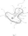
- Figure 1 shows a wearable absorbent article 10 according to an embodiment of the present invention.
- the wearable absorbent article 10 is a diaper, in particular, a refastenable diaper.
- the wearable absorbent article 10 has a main portion 11, a first side portion 12, a second side portion 13 and attachment members 14.
- the main portion 11 is elongate in a first direction.
- the first direction is parallel to a longitudinal centre line 18 of the wearable absorbent article 10.
- the longitudinal centre line 18 extends from a front side 19 of the absorbent article 10, facing a front side of the wearer in use thereof, to a back side 23 of the absorbent article 10, facing a back side of the wearer in use thereof.
- the first side portion 12 and the second side portion 13 extend away from the main portion 11 along a second direction perpendicular to the first direction.
- the first side portion 12 and the second side portion 13 extend away from the main portion 11 on opposite sides of the main portion 11.
- An attachment member 14 is disposed on both side portions 12, 13.
- the wearable absorbent article 10 is configured to be worn around the waist of a user by attaching the side portions 12, 13 to the main portion 11 using the attachment members 14.
- the wearable absorbent article 10 has a liquid permeable top layer adapted to face the wearer during use and adapted to allow a fluid, such as urine or other bodily fluids, to pass through, a liquid impermeable bottom layer adapted to face away from the wearer during use and adapted to prevent the fluid from passing through, and an absorbent core located between the top layer and the bottom layer (see Figures 4 to 6 ) .
- Figure 1 shows the wearable absorbent article 10 in an unfolded configuration. This configuration of the wearable absorbent article 10 is typical before the application of the wearable absorbent article 10 to a wearer.
- the wearable absorbent article 10 comprises a conductor arrangement (see Figures 2 to 4 ) with a flexible circuit board 20.
- the conductor arrangement comprises a plurality of elongate conductors and a plurality of electrodes, each of the electrodes being electrically connected to a respective one of the conductors.
- the flexible circuit board 20 has attached thereto a wetness detection unit 21, a control unit for controlling the wetness detection unit 21, and a power source 30 providing power to the control unit and the wetness detection unit 21, as will be detailed below with reference to Figures 2 to 6 .
- the flexible circuit board 20 may further have a transmitter for transmitting information relating to the wetness detected by the wetness detection unit 21 or other relevant information.
- the flexible circuit board 20 may further have a receiver for receiving information, such as instructions.
- the flexible circuit board 20 is disposed in the main portion 11 of the wearable absorbent article 10, between the absorbent core and the bottom layer (see Figure 4 ).
- the power source 30 may hold an energy store in the form of electrical energy and/or a chemical energy.
- the power source 30 may be any type of power source, such as a cell, a battery and/or a capacitor.
- the power source 30 may be a flexible paper cell/battery, such as those provided by Blue Spark Technologies (OH, US), Enfucell Oy (FI), GS Nanotech (KR) or Cymbet (MN, US).
- Figure 2 shows an exploded view of a first embodiment of a flexible circuit board comprised in the wearable absorbent article 10 shown in Figure 1 .
- Figure 3 illustrates a second embodiment of a flexible circuit board comprised in the wearable absorbent article 10 shown in Figure 1 .
- These two embodiments substantially only differ from each other in the number of conductors and electrodes, i.e., the flexible circuit board of the first embodiment has six conductors and electrodes, while the flexible circuit board of the second embodiment has nine conductors and electrodes.
- reference sign 20 denotes the flexible circuit board (see also Figure 1 ).
- the flexible circuit board 20 comprises an insulating substrate 24 and an insulating layer 25 arranged on top of the substrate 24, as is shown in Figure 2 .
- the insulating layer 25 has a plurality of openings 26.
- the insulating substrate 24 and/or the insulating layer 25 may be made of a polymer material, such as, but not limited to polyethylene terephthalate (PET), polyimide (PI), polyethylene naphthalate (PEN), polyetherimide (PEI) or ethylene vinyl acetate (EVA).
- PET polyethylene terephthalate
- PI polyimide
- PEN polyethylene naphthalate
- PEI polyetherimide
- EVA ethylene vinyl acetate
- the wearable absorbent article 10 comprises a conductor arrangement 2.
- the conductor arrangement 2 comprises a plurality of elongate conductors 4, each conductor extending along the same extension direction.
- the extension direction of the conductors 4 is parallel to the longitudinal centre line 18 of the wearable absorbent article 10 (see Figure 1 ).
- the conductors 4 are provided on the insulating substrate 24 of the flexible circuit board 20.
- the conductors 4 may be strip conductors or strip lines formed on the insulating substrate 24.
- All of the conductors 4 have different lengths from each other in the extension direction, as is shown in Figures 2 and 3(a) . Those of the conductors 4 which have larger lengths in the extension direction have lower electrical resistances per unit length than those of the conductors 4 which have smaller lengths in the extension direction.
- those of the conductors 4 which have larger lengths in the extension direction have cross-sectional areas perpendicular to the extension direction which are larger than the cross-sectional areas perpendicular to the extension direction of those of the conductors 4 which have smaller lengths in the extension direction.
- the differences in resistance, i.e., overall or total resistance, of the conductors 4 resulting from their different lengths can be reduced or even eliminated in a particularly simple and efficient manner.
- those of the conductors 4 which have larger lengths in the extension direction may be made of materials, e.g., metals and/or metal alloys, having lower electrical resistivities than the materials, e.g., metals and/or metal alloys, of which those of the conductors are made which have smaller lengths in the extension direction.
- the cross-sectional areas and/or the materials of the conductors 4 may be chosen such that all of the conductors 4 have substantially the same electrical resistance.
- Each of the conductors 4 of the conductor arrangement 2 is electrically connected to a respective electrode 6, as is shown in Figures 2 and 3(a) .
- each of the electrodes 6 is electrically connected to a respective conductor 4 at the distal end of the conductor 4 in the extension direction thereof, i.e., the end of the conductor 4 which is disposed further away from the wetness detection unit 21.
- All of the electrodes 6 extend along the same extension direction.
- the extension direction of the electrodes 6 is substantially perpendicular to the extension direction of the conductors 4. All of the electrodes 6 have substantially the same length in the extension direction.
- the conductors 4 and the electrodes 6 are disposed between the insulating substrate 24 and the insulating layer 25 so that the conductors 4 are covered by the insulating layer 25 and the electrodes 6 are exposed through the openings 26 (see Figure 2 ). In this way, it can be reliably ensured that the conductors 4 are electrically insulated from the absorbent core of the wearable absorbent article 10 (see Figures 4 to 6 ), while the electrodes 6 can be arranged in contact with the absorbent core in a simple and efficient manner. In this way, upon the occurrence of a wetness event in the absorbent core, an electrical contact is established between a respective one or respective ones of the electrodes 6 and the absorbent core.
- the wetness detector 21 is configured to detect the wetness at the one or more locations within the absorbent core by measuring the electrical resistance between adjacent ones of the electrodes 6, i.e., electrodes 6 which are adjacent to each other, through the conductors 4. In particular, this electrical resistance is measured at electrical contacts 27, each of which is electrically connected to a respective conductor 4 at a proximal end of the conductor 4 in the extension direction thereof, i.e., at the end of the conductor 4 which is disposed closer to the wetness detection unit 21 (see Figures 3(a) and (b) ). These electrical contacts 27 are arranged adjacent to each other along the extension direction of the conductors 4, i.e., along the longitudinal centre line 18 of the wearable absorbent article 10.
- Figure 4 is a cross-sectional view of the wearable absorbent article 10 shown in Figure 1 comprising the flexible circuit board 20 shown in Figure 2 .
- the cross-sectional view of Figure 4 is taken along a plane perpendicular to the second direction (see Figure 1 ).
- the cross-sectional view is a cross-sectional view of the main portion 11 of the wearable absorbent article 10 (see Figure 1 ).
- the wearable absorbent article 10 shown in Figure 4 has a liquid permeable top layer 16 adapted to face the wearer during use and to allow a fluid, such as urine or other bodily fluids, to pass through, a liquid impermeable bottom layer 15 opposite to the top layer 16, which is adapted to prevent the fluid from passing through, and an absorbent core 17 located between the bottom layer 15 and the top layer 16 for absorbing the fluid.
- a fluid such as urine or other bodily fluids
- the flexible circuit board 20 comprising the insulating substrate 24 and the insulating layer 25, is arranged between the absorbent core 17 and the bottom layer 15.
- the flexible circuit board 20 is disposed so that the insulating substrate 24 faces the bottom layer 15 and the insulating layer 25 faces the absorbent core 17.
- the flexible circuit board 20 is arranged so that the electrodes 6 (see Figures 2 and 3 ) are in contact with the absorbent core 17, while the conductors 4 are electrically insulated from the absorbent core 17 by the insulating layer 25, as has been detailed above.
- the electrodes 6 see Figures 2 and 3
- the conductors 4 are electrically insulated from the absorbent core 17 by the insulating layer 25, as has been detailed above.
- an electrical contact is established between respective ones of the electrodes 6 and the absorbent core 17. In this way, an electrical contact is established between at least two of the electrodes 6 through the absorbent core 17.
- the wetness detection unit 21 (not shown in Figure 4 ) is configured to detect the wetness at the one or more locations within the absorbent core 17 by measuring the electrical resistance between at least two, e.g., adjacent ones, of the electrodes 6 through the conductors 4. The electrical resistance is measured at the electrical contacts 27 (see Figures 3(a) and (b) ), as has been detailed above. The wetness measurement performed by the wetness detection unit 21 will be explained in more detail below with reference to Figures 5 and 6 .
- the conductor arrangement 2, the electrodes 6, the wetness detection unit 21, the power source 30 and the control unit 29 together form a wetness sensor.
- the wearable absorbent article 10 has the liquid permeable top layer 16 adapted to face the wearer during use and to allow a fluid, such as urine or other bodily fluids, to pass through, the liquid impermeable bottom layer 15 opposite to the top layer 16, which is adapted to prevent the fluid from passing through, and the absorbent core 17 located between the bottom layer 15 and the top layer 16 for absorbing the fluid.
- a fluid such as urine or other bodily fluids
- the flexible circuit board 20 (not shown in Figures 5 and 6 ) is arranged so that the electrodes 6 (see Figures 2 and 3 ) are in contact with the absorbent core 17, while the conductors 4 are electrically insulated from the absorbent core 17 by the insulating layer 25, as has been detailed above.
- an electrical contact is established between respective ones of the electrodes 6 and the absorbent core 17. In this way, an electrical contact is established between at least two of the electrodes 6 through the absorbent core 17.
- the wetness detection unit 21 is configured to detect the wetness at the one or more locations within the absorbent core 17 by measuring the electrical resistance between at least two, e.g., adjacent ones, of the electrodes 6 through the conductors 4. The electrical resistance is measured at the electrical contacts 27 (see Figures 3(a) and (b) ), as has been detailed above.
- the electrical conductivity of the portion or portions of the absorbent core 17 at which the event occurs increases due to the presence of a fluid, such as urine or other bodily fluids, in the portion or portions.
- a fluid such as urine or other bodily fluids
- the electrical resistance between at least two, e.g., adjacent ones, of the electrodes 6 in the vicinity of this portion or these portions or at this portion or these portions decreases. This change in resistance is measured by the wetness detection unit 21 through the conductors 4 which are electrically connected to the respective electrodes 6.
- the degree of the resistance change measured by the wetness detection unit 21 depends on the amount of fluid present in the portion or portions, i.e., on the intensity of the wetness event. Therefore, by measuring the degree of the resistance change, the wetness detection unit 21 can determine the level of saturation of the wearable absorbent article 10, i.e., of the absorbent core 17, so that the user or carer can be alerted to saturation or impending saturation of the absorbent article 10.
- the control unit 29 is configured to control the wetness detection unit 21.
- the control unit 29 may be configured to process the data measured by the wetness detection unit 21.
- the control unit 29 may be any type of control, such as, for example, a microprocessor.
- the control unit 29 is electrically connected to the wetness detection unit 21 by a pair of leads 22 (see Figures 5 and 6 ).
- the control unit 29 is arranged at a location distant from the flexible circuit board 20.
- the power source 30 provides power to the control unit 29 and the wetness detection unit 21.
- the power source 30 may be any type of power source, such as a cell, a battery and/or a capacitor, as has been detailed above.
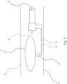
- Figure 5 shows an arrangement in which the wetness detection unit 21, the leads 22, the control unit 29 and the power source 30 are arranged between the bottom layer 15 and the top layer 16 of the wearable absorbent article 10.
- the wetness detection unit 21 is disposed between the absorbent core 17 and the bottom layer 15.
- the wetness detection unit 21 is thus embedded within the remainder of the wearable absorbent article 10. This configuration allows for a particularly simple and secure arrangement of the wetness detection unit 21. In particular, the wetness detection unit 21 is safely protected from any external influences by the bottom layer 15 and the top layer 16 of the wearable absorbent article 10.
- Figure 6 shows an alternative arrangement which differs from the arrangement shown in Figure 5 only in that the leads 22 are not disposed between the bottom layer 15 and the top layer 16. As is shown in Figure 6 , the leads 22 are provided on an outer side of the bottom layer 15. This configuration enables particularly easy access to the leads 22, for example, in the case of any damage thereto.
- the wetness detection unit 21 may not be disposed between the bottom layer 15 and the top layer 16.
- the wetness detection unit 21 may be provided on an outer side of the bottom layer 15.
- the wetness detection unit 21 may be removably attached to the outer side of the bottom layer 15. In this case, the wetness detection unit 21 can be replaced in a particularly simple and efficient manner, for example, if the wetness detection unit 21 is damaged. Moreover, the wetness detection unit 21 can be reused for other wearable absorbent articles in a simple way.
- control unit 29 and/or the power source 30 may not be disposed between the bottom layer 15 and the top layer 16 of the wearable absorbent article 10.
Landscapes
- Health & Medical Sciences (AREA)
- Engineering & Computer Science (AREA)
- General Health & Medical Sciences (AREA)
- Public Health (AREA)
- Heart & Thoracic Surgery (AREA)
- Vascular Medicine (AREA)
- Life Sciences & Earth Sciences (AREA)
- Animal Behavior & Ethology (AREA)
- Veterinary Medicine (AREA)
- Biomedical Technology (AREA)
- Epidemiology (AREA)
- Environmental & Geological Engineering (AREA)
- Nursing (AREA)
- Orthopedic Medicine & Surgery (AREA)
- Absorbent Articles And Supports Therefor (AREA)
- Orthopedics, Nursing, And Contraception (AREA)
- Investigating Or Analyzing Materials By The Use Of Electric Means (AREA)
Claims (11)
- Saugfähiger Wearable-Artikel (10), umfassend:eine Leiteranordnung (2); wobeidie Leiteranordnung (2) eine Vielzahl von langgestreckten Leitern (4) umfasst, wobei sich jeder Leiter (4) entlang einer Erstreckungsrichtung erstreckt,zumindest einige der Leiter (4) in den jeweiligen Erstreckungsrichtungen voneinander unterschiedliche Längen aufweisen, unddiejenigen der zumindest einigen Leiter (4), die in den jeweiligen Erstreckungsrichtungen größere Längen aufweisen, geringere elektrische Widerstände pro Einheitslänge aufweisen als diejenigen der zumindest einigen Leiter (4), die in den jeweiligen Erstreckungsrichtungen geringere Längen aufweisen,wobei der saugfähige Wearable-Artikel (10) weiter einen saugfähigen Kern (17) und eine Nässeerkennungseinheit (21) zum Erkennen von Nässe an einer oder mehreren Stellen innerhalb des saugfähigen Kerns (17) umfasst, wobei die Leiter (4) so angeordnet sind, dass sie vom saugfähigen Kern (17) elektrisch isoliert sind,wobei jeder der Leiter (4) mit einer jeweiligen Elektrode (6) elektrisch verbunden ist, die Elektroden (6) in Kontakt mit dem saugfähigen Kern (17) angeordnet sind, und die Nässeerkennungseinheit (21) so konfiguriert ist, dass sie die Nässe an einer oder mehreren Stellen innerhalb des saugfähigen Kerns (17) erkennt, indem sie den elektrischen Widerstand zwischen zwei der Elektroden (6) durch die Leiter (4) misst,wobei diejenigen der zumindest einigen Leiter (4), die in den jeweiligen Erstreckungsrichtungen größere Längen aufweisen, senkrecht zu den jeweiligen Erstreckungsrichtungen Querschnittsflächen aufweisen, die größer sind als die senkrecht zu den jeweiligen Erstreckungsrichtungen verlaufenden Querschnittsflächen derjenigen der zumindest einigen Leiter (4), die in den jeweiligen Erstreckungsrichtungen geringere Längen aufweisen, undwobei die Querschnittsflächen der Leiter (4) senkrecht zu den jeweiligen Erstreckungsrichtungen im Wesentlichen proportional zu den Längen der Leiter (4) in den jeweiligen Erstreckungsrichtungen sind.
- Saugfähiger Wearable-Artikel (10) nach Anspruch 1, wobei die Nässeerkennungseinheit (21) abnehmbar am Rest des saugfähigen Artikels (10) angebracht ist.
- Saugfähiger Wearable-Artikel (10) nach Anspruch 1, wobei die Nässeerkennungseinheit (21) in den Rest des saugfähigen Artikels (10) eingebettet ist.
- Saugfähiger Wearable-Artikel (10) nach einem der vorstehenden Ansprüche, wobei alle Leiter (4) im Wesentlichen den gleichen elektrischen Widerstand aufweisen.
- Saugfähiger Wearable-Artikel (10) nach einem der vorstehenden Ansprüche, wobei diejenigen der zumindest einigen Leiter (4), die in den jeweiligen Erstreckungsrichtungen größere Längen aufweisen, einen geringeren elektrischen Widerstand aufweisen als diejenigen der zumindest einigen Leiter (4), die in den jeweiligen Erstreckungsrichtungen geringere Längen aufweisen.
- Saugfähiger Wearable-Artikel (10) nach Anspruch 5, wobei die elektrischen Widerstände der Leiter (4) umgekehrt proportional zu den Längen der Leiter (4) in den jeweiligen Erstreckungsrichtungen sind.
- Saugfähiger Wearable-Artikel (10) nach einem der vorstehenden Ansprüche, wobei alle Leiter (4) sich entlang der gleichen Erstreckungsrichtung erstrecken.
- Saugfähiger Wearable-Artikel (10) nach einem der vorstehenden Ansprüche, wobei die Leiteranordnung (2) weiter eine flexible Leiterplatte (20) umfasst.
- Saugfähiger Wearable-Artikel (10) nach Anspruch 8, wobei die Leiter (4) auf der flexiblen Leiterplatte (20) ausgebildete Streifenleiter sind.
- Saugfähiger Wearable-Artikel (10) nach einem der vorstehenden Ansprüche, wobei die Leiter (4) Längen in den jeweiligen Erstreckungsrichtungen im Bereich von 1 cm bis 60 cm und/oder Querschnittsflächen senkrecht zu den jeweiligen Erstreckungsrichtungen im Bereich von 0,01 mm2 bis 1,00 mm2 aufweisen.
- Saugfähiger Wearable-Artikel (10) nach einem der vorstehenden Ansprüche, wobei der saugfähige Artikel (10) eine Windel, eine Damenbinde, ein Inkontinenzkleidungsstück oder ein medizinischer Verband ist.
Priority Applications (1)
| Application Number | Priority Date | Filing Date | Title |
|---|---|---|---|
| PL15813465.0T PL3393416T5 (pl) | 2015-12-22 | 2015-12-22 | Wyrób chłonny do zakładania |
Applications Claiming Priority (1)
| Application Number | Priority Date | Filing Date | Title |
|---|---|---|---|
| PCT/EP2015/081036 WO2017108109A1 (en) | 2015-12-22 | 2015-12-22 | Wearable absorbent article |
Publications (3)
| Publication Number | Publication Date |
|---|---|
| EP3393416A1 EP3393416A1 (de) | 2018-10-31 |
| EP3393416B1 EP3393416B1 (de) | 2020-04-15 |
| EP3393416B2 true EP3393416B2 (de) | 2025-01-15 |
Family
ID=54937095
Family Applications (1)
| Application Number | Title | Priority Date | Filing Date |
|---|---|---|---|
| EP15813465.0A Active EP3393416B2 (de) | 2015-12-22 | 2015-12-22 | Saugfähiger wearable-artikel |
Country Status (12)
| Country | Link |
|---|---|
| US (1) | US10307303B2 (de) |
| EP (1) | EP3393416B2 (de) |
| JP (1) | JP6700399B2 (de) |
| CN (1) | CN108430411B (de) |
| AU (1) | AU2015418506B2 (de) |
| BR (1) | BR112018008780B1 (de) |
| CA (1) | CA3008224C (de) |
| DK (1) | DK3393416T4 (de) |
| MX (1) | MX374872B (de) |
| PL (1) | PL3393416T5 (de) |
| RU (1) | RU2699553C1 (de) |
| WO (1) | WO2017108109A1 (de) |
Families Citing this family (35)
| Publication number | Priority date | Publication date | Assignee | Title |
|---|---|---|---|---|
| PL3393416T5 (pl) * | 2015-12-22 | 2025-04-28 | Essity Hygiene And Health Aktiebolag | Wyrób chłonny do zakładania |
| US11141100B2 (en) | 2015-12-23 | 2021-10-12 | Coloplast A/S | Moisture assessment system and method for wound care |
| US10492959B2 (en) * | 2017-05-07 | 2019-12-03 | Dongguan Southstar Electronics Limited | Method for indicating and alarming about wet level of diaper |
| WO2019096413A1 (en) | 2017-11-17 | 2019-05-23 | Essity Hygiene And Health Aktiebolag | A hygiene monitoring device comprising an electrode panel |
| AU2018391313B2 (en) | 2017-12-22 | 2024-05-02 | Coloplast A/S | Accessory devices of an ostomy system, and related methods for communicating operating state |
| EP3727231B2 (de) | 2017-12-22 | 2025-03-12 | Coloplast A/S | Verarbeitungsschemata für ein stomasystem, überwachungsvorrichtung für eine stomavorrichtung und zugehörige verfahren |
| WO2019120435A1 (en) | 2017-12-22 | 2019-06-27 | Coloplast A/S | Ostomy appliance with selective sensor points and related methods |
| WO2019120445A1 (en) | 2017-12-22 | 2019-06-27 | Coloplast A/S | Base plate and sensor assembly of an ostomy system having a leakage sensor |
| EP4180010A1 (de) | 2017-12-22 | 2023-05-17 | Coloplast A/S | Sensorbauteil eines stomasystems mit feuchtigkeitssensor |
| US10799385B2 (en) | 2017-12-22 | 2020-10-13 | Coloplast A/S | Ostomy appliance with layered base plate |
| AU2018386865B2 (en) | 2017-12-22 | 2024-03-14 | Coloplast A/S | Ostomy system and monitor device with angular leakage detection |
| EP3727220B1 (de) | 2017-12-22 | 2023-07-12 | Coloplast A/S | Stomasystem, überwachungsvorrichtung und verfahren zur überwachung eines stomas |
| WO2019120452A1 (en) | 2017-12-22 | 2019-06-27 | Coloplast A/S | Coupling part with a hinge for an ostomy base plate and sensor assembly part |
| US10500084B2 (en) | 2017-12-22 | 2019-12-10 | Coloplast A/S | Accessory devices of an ostomy system, and related methods for communicating leakage state |
| WO2019120430A1 (en) | 2017-12-22 | 2019-06-27 | Coloplast A/S | Data transmission schemes for an ostomy system, monitor device for an ostomy appliance and related methods |
| US11590015B2 (en) | 2017-12-22 | 2023-02-28 | Coloplast A/S | Sensor assembly part and a base plate for a medical appliance and a method for manufacturing a sensor assembly part and a base plate |
| WO2019120424A1 (en) | 2017-12-22 | 2019-06-27 | Coloplast A/S | Moisture detecting base plate for an ostomy appliance and a system for determining moisture propagation in a base plate and/or a sensor assembly part |
| CN111447896B (zh) | 2017-12-22 | 2023-03-28 | 科洛普拉斯特公司 | 用于造口术器具的底板、用于造口术器具的监测装置和系统 |
| EP4042987B1 (de) | 2017-12-22 | 2025-02-12 | Coloplast A/S | Überwachungsvorrichtung für ein stomasystem mit einem verbinder zur verbindung mit einer grundplatte und einer zubehörvorrichtung |
| EP3755286B1 (de) | 2018-02-20 | 2025-04-30 | Coloplast A/S | Zubehörgeräte für ein stomasystem und zugehörige verfahren zum wechseln einer stomavorrichtung auf der grundlage eines zukünftigen betriebszustands |
| EP3755283B1 (de) | 2018-02-20 | 2024-05-01 | Coloplast A/S | Sensorbaugruppenteil und eine grundplatte und ein stomabeutel für eine stomavorrichtung und vorrichtung zum anschluss an eine grundplatte und/oder ein sensorbaugruppenteil |
| US11903728B2 (en) | 2018-03-15 | 2024-02-20 | Coloplast A/S | Methods of configuring medical notifications and related accessory devices |
| LT3764961T (lt) | 2018-03-15 | 2024-03-25 | Coloplast A/S | Aparatas ir būdai ostomijos prietaiso vartotojo navigacijai į persisirengimo kambarį |
| CN112567221B (zh) | 2018-08-15 | 2024-06-25 | 科洛普拉斯特公司 | 造口术系统的附属装置、以及用于问题识别的相关方法 |
| US12064258B2 (en) | 2018-12-20 | 2024-08-20 | Coloplast A/S | Ostomy condition classification with image data transformation, devices and related methods |
| LT3897481T (lt) | 2018-12-20 | 2023-09-11 | Coloplast A/S | Ostomijos būklės klasifikacija su maskavimu, įrenginiai ir susiję būdai |
| KR102825171B1 (ko) | 2019-01-31 | 2025-06-25 | 컬러플라스트 에이/에스 | 장루ㆍ요루 기구용 센서 패치 |
| CN113365581B (zh) | 2019-01-31 | 2024-12-31 | 科洛普拉斯特公司 | 造口传感器贴片的应用 |
| AU2020214098B2 (en) | 2019-01-31 | 2025-01-02 | Coloplast A/S | A stomal sensor patch |
| WO2020173534A1 (en) | 2019-02-28 | 2020-09-03 | Coloplast A/S | A sensor patch for attachment to a base plate |
| CN111839903B (zh) * | 2019-04-24 | 2023-01-13 | 飞矩科技(上海)有限公司 | 一种智能卫生护理用品及其制备方法 |
| ES2955577T3 (es) | 2019-07-03 | 2023-12-04 | Ontex Bv | Sustrato, artículo absorbente para supervisión de humedad |
| CN113116640A (zh) * | 2021-04-23 | 2021-07-16 | 嘉兴聚鑫隆科技有限公司 | 一种感应污染区域大小的智能尿布 |
| USD1071226S1 (en) * | 2021-04-30 | 2025-04-15 | VestConn Inc. | Monitoring device |
| CN115024898B (zh) * | 2022-06-09 | 2023-08-18 | 保定市芊紫纸制品制造有限公司 | 一种可用于智能健康辅助检测的卫生巾 |
Citations (11)
| Publication number | Priority date | Publication date | Assignee | Title |
|---|---|---|---|---|
| US4356818A (en) † | 1979-12-03 | 1982-11-02 | Helene Macias | Diaper with moisture detecting apparatus |
| US20050156744A1 (en) † | 2003-09-02 | 2005-07-21 | Pires Harold G. | Diaper wetness annunciator system |
| US20080051745A1 (en) † | 2006-08-25 | 2008-02-28 | Andrew Mark Long | Systems and methods for hydration sensing and monitoring |
| WO2008026120A2 (en) † | 2006-08-31 | 2008-03-06 | Kimberly-Clark Worldwide, Inc. | Electrical conductivity bridge in a conductive multilayer article |
| KR20110113008A (ko) † | 2010-04-08 | 2011-10-14 | (주)피앤폴 | 대소변 감지기능 갖는 기능성 기저귀 |
| WO2011145787A1 (ko) † | 2010-05-19 | 2011-11-24 | Kim Dong-Gyu | 재사용할 수 있는 자동 대소변 감지장치 |
| US20130307570A1 (en) † | 2010-12-23 | 2013-11-21 | Sca Hygiene Products Ab | Absorbent article comprising a liquid discharge sensor |
| US20130321007A1 (en) † | 2010-12-23 | 2013-12-05 | Sca Hygiene Products Ab | Absorbent article comprising a liquid discharge detection sensor |
| US20140350503A1 (en) † | 2011-12-23 | 2014-11-27 | Sca Hygiene Products Ab | Method for detecting a liquid discharge to an absorbent article |
| US20140371702A1 (en) † | 2011-12-29 | 2014-12-18 | Sca Hygiene Products Ab | Absorbent article comprising a wetness detector |
| WO2015068124A1 (en) † | 2013-11-06 | 2015-05-14 | Joseph Chiu | Urine detection inductor suitable for large-scale production |
Family Cites Families (22)
| Publication number | Priority date | Publication date | Assignee | Title |
|---|---|---|---|---|
| US5469145A (en) * | 1992-05-29 | 1995-11-21 | Johnson; Lonnie | Wet diaper detector |
| US5266928A (en) * | 1992-05-29 | 1993-11-30 | Johnson Lonnie G | Wet diaper detector |
| US5838240A (en) * | 1992-05-29 | 1998-11-17 | Johnson Research & Development Company, Inc. | Wet diaper detector |
| US5659294A (en) * | 1994-05-17 | 1997-08-19 | Vdo Adolf Schindling Ag | Rain sensor |
| JP3376769B2 (ja) * | 1995-07-21 | 2003-02-10 | 株式会社デンソー | おむつの交換時期検知装置 |
| AU4324299A (en) * | 1998-05-28 | 1999-12-13 | Safieh Bahramian Fard | Wetness awareness training device |
| JP2000093448A (ja) * | 1998-09-18 | 2000-04-04 | Panetto:Kk | おむつ用センサおよびこれを内蔵したおむつ |
| US7250547B1 (en) * | 2000-11-07 | 2007-07-31 | Rf Technologies, Inc. | Wetness monitoring system |
| US7504550B2 (en) * | 2006-08-31 | 2009-03-17 | Kimberly-Clark Worldwide, Inc. | Conductive porous materials |
| US8264362B2 (en) * | 2007-04-30 | 2012-09-11 | Kimberly-Clark Worldwide, Inc. | Embedded antenna for sensing article |
| CN101629926A (zh) * | 2008-07-18 | 2010-01-20 | 王建敏 | 一种感应垫 |
| JP2011019726A (ja) * | 2009-07-16 | 2011-02-03 | Akita Techno Design:Kk | おむつ交換検知センサー及びおむつ交換検知センサー専用装着アダプター |
| GB201022028D0 (en) | 2010-12-23 | 2011-02-02 | Sca Hygiene Prod Ab | Tool for analysing liquid discharge data in an absorbent article, an absorbent article adapted for liquid dicharge data collection and a control unit |
| US10111787B2 (en) * | 2012-08-28 | 2018-10-30 | Agency For Science, Technology And Research | Apparatus for a diaper, a system, a diaper and a method of manufacturing an electrode |
| US9719951B1 (en) * | 2013-07-12 | 2017-08-01 | Helvetia Wireless Llc | Method and apparatus for moisture detection |
| DE112014003621B4 (de) * | 2013-08-08 | 2022-07-14 | The Procter & Gamble Company | Sensorsysteme für absorbierende Gegenstände umfassend Sensorschleusen |
| CN103655050A (zh) * | 2013-11-25 | 2014-03-26 | 西安信唯信息科技有限公司 | 一种适合规模化生产的尿液检测感应体 |
| JP6275473B2 (ja) * | 2013-12-20 | 2018-02-07 | 花王株式会社 | 着用物品 |
| US9910003B1 (en) * | 2014-12-18 | 2018-03-06 | Helvetia Wireless, Llc | Methods and apparatus for a moisture detector |
| PL3393416T5 (pl) * | 2015-12-22 | 2025-04-28 | Essity Hygiene And Health Aktiebolag | Wyrób chłonny do zakładania |
| US10028865B2 (en) * | 2016-06-13 | 2018-07-24 | Verily Life Sciences Llc | Hardware to determine when a diaper needs to be changed and provide electronic notification |
| US10299723B2 (en) * | 2016-06-13 | 2019-05-28 | Verily Life Sciences Llc | Ultra-low power one-shot hydration sensing system |
-
2015
- 2015-12-22 PL PL15813465.0T patent/PL3393416T5/pl unknown
- 2015-12-22 CA CA3008224A patent/CA3008224C/en active Active
- 2015-12-22 JP JP2018532657A patent/JP6700399B2/ja active Active
- 2015-12-22 US US16/064,615 patent/US10307303B2/en active Active
- 2015-12-22 CN CN201580085537.5A patent/CN108430411B/zh active Active
- 2015-12-22 RU RU2018126485A patent/RU2699553C1/ru active
- 2015-12-22 AU AU2015418506A patent/AU2015418506B2/en active Active
- 2015-12-22 MX MX2018007578A patent/MX374872B/es active IP Right Grant
- 2015-12-22 WO PCT/EP2015/081036 patent/WO2017108109A1/en not_active Ceased
- 2015-12-22 DK DK15813465.0T patent/DK3393416T4/da active
- 2015-12-22 EP EP15813465.0A patent/EP3393416B2/de active Active
- 2015-12-22 BR BR112018008780-7A patent/BR112018008780B1/pt active IP Right Grant
Patent Citations (11)
| Publication number | Priority date | Publication date | Assignee | Title |
|---|---|---|---|---|
| US4356818A (en) † | 1979-12-03 | 1982-11-02 | Helene Macias | Diaper with moisture detecting apparatus |
| US20050156744A1 (en) † | 2003-09-02 | 2005-07-21 | Pires Harold G. | Diaper wetness annunciator system |
| US20080051745A1 (en) † | 2006-08-25 | 2008-02-28 | Andrew Mark Long | Systems and methods for hydration sensing and monitoring |
| WO2008026120A2 (en) † | 2006-08-31 | 2008-03-06 | Kimberly-Clark Worldwide, Inc. | Electrical conductivity bridge in a conductive multilayer article |
| KR20110113008A (ko) † | 2010-04-08 | 2011-10-14 | (주)피앤폴 | 대소변 감지기능 갖는 기능성 기저귀 |
| WO2011145787A1 (ko) † | 2010-05-19 | 2011-11-24 | Kim Dong-Gyu | 재사용할 수 있는 자동 대소변 감지장치 |
| US20130307570A1 (en) † | 2010-12-23 | 2013-11-21 | Sca Hygiene Products Ab | Absorbent article comprising a liquid discharge sensor |
| US20130321007A1 (en) † | 2010-12-23 | 2013-12-05 | Sca Hygiene Products Ab | Absorbent article comprising a liquid discharge detection sensor |
| US20140350503A1 (en) † | 2011-12-23 | 2014-11-27 | Sca Hygiene Products Ab | Method for detecting a liquid discharge to an absorbent article |
| US20140371702A1 (en) † | 2011-12-29 | 2014-12-18 | Sca Hygiene Products Ab | Absorbent article comprising a wetness detector |
| WO2015068124A1 (en) † | 2013-11-06 | 2015-05-14 | Joseph Chiu | Urine detection inductor suitable for large-scale production |
Also Published As
| Publication number | Publication date |
|---|---|
| JP2019503759A (ja) | 2019-02-14 |
| PL3393416T3 (pl) | 2020-08-24 |
| CN108430411A (zh) | 2018-08-21 |
| MX2018007578A (es) | 2019-02-14 |
| AU2015418506A1 (en) | 2018-05-10 |
| AU2015418506B2 (en) | 2018-10-04 |
| BR112018008780B1 (pt) | 2022-05-03 |
| DK3393416T3 (da) | 2020-05-25 |
| CA3008224C (en) | 2020-03-24 |
| DK3393416T4 (da) | 2025-02-17 |
| EP3393416A1 (de) | 2018-10-31 |
| JP6700399B2 (ja) | 2020-05-27 |
| MX374872B (es) | 2025-03-06 |
| CA3008224A1 (en) | 2017-06-29 |
| PL3393416T5 (pl) | 2025-04-28 |
| US20180369025A1 (en) | 2018-12-27 |
| RU2699553C1 (ru) | 2019-09-06 |
| CN108430411B (zh) | 2021-02-26 |
| WO2017108109A1 (en) | 2017-06-29 |
| BR112018008780A2 (pt) | 2019-01-15 |
| US10307303B2 (en) | 2019-06-04 |
| EP3393416B1 (de) | 2020-04-15 |
Similar Documents
| Publication | Publication Date | Title |
|---|---|---|
| EP3393416B2 (de) | Saugfähiger wearable-artikel | |
| EP3685811B1 (de) | Urindetektionsvorrichtung mit klebeband und emittersensor | |
| US9314381B2 (en) | Capacitive wetness sensor and method for manufacturing the same | |
| JP6275473B2 (ja) | 着用物品 | |
| EP3897497B1 (de) | Hygieneüberwachungsvorrichtung mit einer sensortafel | |
| EP3632382B1 (de) | Mit einem sensor ausgestatteter am körper tragbarer artikel | |
| EP3968927B1 (de) | Hygieneüberwachungsvorrichtung mit schmaler datenprotokollierungseinheit | |
| CN111110451A (zh) | 一种智能纸尿裤 | |
| EP3897496B1 (de) | System mit einem tragbaren absorbierenden hygieneartikel und einer hygieneüberwachungsvorrichtung | |
| US20250205090A1 (en) | Absorbent article with leakage probability algorithm | |
| CN119698268A (zh) | 用于感测吸收性物品的填充状态的传感器布置结构 | |
| BR112021011142B1 (pt) | Sistema, kit, dispositivo de monitoramento de higiene e método |
Legal Events
| Date | Code | Title | Description |
|---|---|---|---|
| STAA | Information on the status of an ep patent application or granted ep patent |
Free format text: STATUS: THE INTERNATIONAL PUBLICATION HAS BEEN MADE |
|
| PUAI | Public reference made under article 153(3) epc to a published international application that has entered the european phase |
Free format text: ORIGINAL CODE: 0009012 |
|
| STAA | Information on the status of an ep patent application or granted ep patent |
Free format text: STATUS: REQUEST FOR EXAMINATION WAS MADE |
|
| 17P | Request for examination filed |
Effective date: 20180629 |
|
| AK | Designated contracting states |
Kind code of ref document: A1 Designated state(s): AL AT BE BG CH CY CZ DE DK EE ES FI FR GB GR HR HU IE IS IT LI LT LU LV MC MK MT NL NO PL PT RO RS SE SI SK SM TR |
|
| AX | Request for extension of the european patent |
Extension state: BA ME |
|
| DAV | Request for validation of the european patent (deleted) | ||
| DAX | Request for extension of the european patent (deleted) | ||
| GRAP | Despatch of communication of intention to grant a patent |
Free format text: ORIGINAL CODE: EPIDOSNIGR1 |
|
| STAA | Information on the status of an ep patent application or granted ep patent |
Free format text: STATUS: GRANT OF PATENT IS INTENDED |
|
| INTG | Intention to grant announced |
Effective date: 20190628 |
|
| GRAJ | Information related to disapproval of communication of intention to grant by the applicant or resumption of examination proceedings by the epo deleted |
Free format text: ORIGINAL CODE: EPIDOSDIGR1 |
|
| STAA | Information on the status of an ep patent application or granted ep patent |
Free format text: STATUS: REQUEST FOR EXAMINATION WAS MADE |
|
| GRAP | Despatch of communication of intention to grant a patent |
Free format text: ORIGINAL CODE: EPIDOSNIGR1 |
|
| STAA | Information on the status of an ep patent application or granted ep patent |
Free format text: STATUS: GRANT OF PATENT IS INTENDED |
|
| INTC | Intention to grant announced (deleted) | ||
| INTG | Intention to grant announced |
Effective date: 20191028 |
|
| GRAS | Grant fee paid |
Free format text: ORIGINAL CODE: EPIDOSNIGR3 |
|
| GRAA | (expected) grant |
Free format text: ORIGINAL CODE: 0009210 |
|
| STAA | Information on the status of an ep patent application or granted ep patent |
Free format text: STATUS: THE PATENT HAS BEEN GRANTED |
|
| RIN1 | Information on inventor provided before grant (corrected) |
Inventor name: SCHVETZ, YOSSEF Inventor name: TRAMONTANA, MANUEL Inventor name: OZSUMER, SERDAR Inventor name: CARNEY, JOSHUA DANIEL Inventor name: LOCATI, ALESSANDRO |
|
| AK | Designated contracting states |
Kind code of ref document: B1 Designated state(s): AL AT BE BG CH CY CZ DE DK EE ES FI FR GB GR HR HU IE IS IT LI LT LU LV MC MK MT NL NO PL PT RO RS SE SI SK SM TR |
|
| REG | Reference to a national code |
Ref country code: CH Ref legal event code: EP |
|
| REG | Reference to a national code |
Ref country code: DE Ref legal event code: R096 Ref document number: 602015050829 Country of ref document: DE |
|
| REG | Reference to a national code |
Ref country code: IE Ref legal event code: FG4D |
|
| REG | Reference to a national code |
Ref country code: AT Ref legal event code: REF Ref document number: 1256435 Country of ref document: AT Kind code of ref document: T Effective date: 20200515 |
|
| REG | Reference to a national code |
Ref country code: DK Ref legal event code: T3 Effective date: 20200520 |
|
| REG | Reference to a national code |
Ref country code: NL Ref legal event code: FP |
|
| REG | Reference to a national code |
Ref country code: LT Ref legal event code: MG4D |
|
| PG25 | Lapsed in a contracting state [announced via postgrant information from national office to epo] |
Ref country code: PT Free format text: LAPSE BECAUSE OF FAILURE TO SUBMIT A TRANSLATION OF THE DESCRIPTION OR TO PAY THE FEE WITHIN THE PRESCRIBED TIME-LIMIT Effective date: 20200817 Ref country code: LT Free format text: LAPSE BECAUSE OF FAILURE TO SUBMIT A TRANSLATION OF THE DESCRIPTION OR TO PAY THE FEE WITHIN THE PRESCRIBED TIME-LIMIT Effective date: 20200415 Ref country code: GR Free format text: LAPSE BECAUSE OF FAILURE TO SUBMIT A TRANSLATION OF THE DESCRIPTION OR TO PAY THE FEE WITHIN THE PRESCRIBED TIME-LIMIT Effective date: 20200716 Ref country code: FI Free format text: LAPSE BECAUSE OF FAILURE TO SUBMIT A TRANSLATION OF THE DESCRIPTION OR TO PAY THE FEE WITHIN THE PRESCRIBED TIME-LIMIT Effective date: 20200415 Ref country code: SE Free format text: LAPSE BECAUSE OF FAILURE TO SUBMIT A TRANSLATION OF THE DESCRIPTION OR TO PAY THE FEE WITHIN THE PRESCRIBED TIME-LIMIT Effective date: 20200415 Ref country code: NO Free format text: LAPSE BECAUSE OF FAILURE TO SUBMIT A TRANSLATION OF THE DESCRIPTION OR TO PAY THE FEE WITHIN THE PRESCRIBED TIME-LIMIT Effective date: 20200715 Ref country code: IS Free format text: LAPSE BECAUSE OF FAILURE TO SUBMIT A TRANSLATION OF THE DESCRIPTION OR TO PAY THE FEE WITHIN THE PRESCRIBED TIME-LIMIT Effective date: 20200815 |
|
| REG | Reference to a national code |
Ref country code: AT Ref legal event code: MK05 Ref document number: 1256435 Country of ref document: AT Kind code of ref document: T Effective date: 20200415 |
|
| PG25 | Lapsed in a contracting state [announced via postgrant information from national office to epo] |
Ref country code: RS Free format text: LAPSE BECAUSE OF FAILURE TO SUBMIT A TRANSLATION OF THE DESCRIPTION OR TO PAY THE FEE WITHIN THE PRESCRIBED TIME-LIMIT Effective date: 20200415 Ref country code: HR Free format text: LAPSE BECAUSE OF FAILURE TO SUBMIT A TRANSLATION OF THE DESCRIPTION OR TO PAY THE FEE WITHIN THE PRESCRIBED TIME-LIMIT Effective date: 20200415 Ref country code: BG Free format text: LAPSE BECAUSE OF FAILURE TO SUBMIT A TRANSLATION OF THE DESCRIPTION OR TO PAY THE FEE WITHIN THE PRESCRIBED TIME-LIMIT Effective date: 20200715 Ref country code: LV Free format text: LAPSE BECAUSE OF FAILURE TO SUBMIT A TRANSLATION OF THE DESCRIPTION OR TO PAY THE FEE WITHIN THE PRESCRIBED TIME-LIMIT Effective date: 20200415 |
|
| PG25 | Lapsed in a contracting state [announced via postgrant information from national office to epo] |
Ref country code: AL Free format text: LAPSE BECAUSE OF FAILURE TO SUBMIT A TRANSLATION OF THE DESCRIPTION OR TO PAY THE FEE WITHIN THE PRESCRIBED TIME-LIMIT Effective date: 20200415 |
|
| REG | Reference to a national code |
Ref country code: DE Ref legal event code: R026 Ref document number: 602015050829 Country of ref document: DE |
|
| PLBI | Opposition filed |
Free format text: ORIGINAL CODE: 0009260 |
|
| PLAX | Notice of opposition and request to file observation + time limit sent |
Free format text: ORIGINAL CODE: EPIDOSNOBS2 |
|
| PG25 | Lapsed in a contracting state [announced via postgrant information from national office to epo] |
Ref country code: CZ Free format text: LAPSE BECAUSE OF FAILURE TO SUBMIT A TRANSLATION OF THE DESCRIPTION OR TO PAY THE FEE WITHIN THE PRESCRIBED TIME-LIMIT Effective date: 20200415 Ref country code: RO Free format text: LAPSE BECAUSE OF FAILURE TO SUBMIT A TRANSLATION OF THE DESCRIPTION OR TO PAY THE FEE WITHIN THE PRESCRIBED TIME-LIMIT Effective date: 20200415 Ref country code: AT Free format text: LAPSE BECAUSE OF FAILURE TO SUBMIT A TRANSLATION OF THE DESCRIPTION OR TO PAY THE FEE WITHIN THE PRESCRIBED TIME-LIMIT Effective date: 20200415 Ref country code: ES Free format text: LAPSE BECAUSE OF FAILURE TO SUBMIT A TRANSLATION OF THE DESCRIPTION OR TO PAY THE FEE WITHIN THE PRESCRIBED TIME-LIMIT Effective date: 20200415 Ref country code: EE Free format text: LAPSE BECAUSE OF FAILURE TO SUBMIT A TRANSLATION OF THE DESCRIPTION OR TO PAY THE FEE WITHIN THE PRESCRIBED TIME-LIMIT Effective date: 20200415 Ref country code: SM Free format text: LAPSE BECAUSE OF FAILURE TO SUBMIT A TRANSLATION OF THE DESCRIPTION OR TO PAY THE FEE WITHIN THE PRESCRIBED TIME-LIMIT Effective date: 20200415 |
|
| 26 | Opposition filed |
Opponent name: MAIWALD PATENT- UND RECHTSANWALTSGESELLSCHAFT MBH Effective date: 20210114 |
|
| PG25 | Lapsed in a contracting state [announced via postgrant information from national office to epo] |
Ref country code: SK Free format text: LAPSE BECAUSE OF FAILURE TO SUBMIT A TRANSLATION OF THE DESCRIPTION OR TO PAY THE FEE WITHIN THE PRESCRIBED TIME-LIMIT Effective date: 20200415 |
|
| PLAB | Opposition data, opponent's data or that of the opponent's representative modified |
Free format text: ORIGINAL CODE: 0009299OPPO |
|
| PLBB | Reply of patent proprietor to notice(s) of opposition received |
Free format text: ORIGINAL CODE: EPIDOSNOBS3 |
|
| R26 | Opposition filed (corrected) |
Opponent name: MAIWALD PATENT- UND RECHTSANWALTSGESELLSCHAFT MBH Effective date: 20210114 |
|
| PG25 | Lapsed in a contracting state [announced via postgrant information from national office to epo] |
Ref country code: SI Free format text: LAPSE BECAUSE OF FAILURE TO SUBMIT A TRANSLATION OF THE DESCRIPTION OR TO PAY THE FEE WITHIN THE PRESCRIBED TIME-LIMIT Effective date: 20200415 |
|
| REG | Reference to a national code |
Ref country code: CH Ref legal event code: PL |
|
| PG25 | Lapsed in a contracting state [announced via postgrant information from national office to epo] |
Ref country code: MC Free format text: LAPSE BECAUSE OF FAILURE TO SUBMIT A TRANSLATION OF THE DESCRIPTION OR TO PAY THE FEE WITHIN THE PRESCRIBED TIME-LIMIT Effective date: 20200415 |
|
| REG | Reference to a national code |
Ref country code: BE Ref legal event code: MM Effective date: 20201231 |
|
| PG25 | Lapsed in a contracting state [announced via postgrant information from national office to epo] |
Ref country code: LU Free format text: LAPSE BECAUSE OF NON-PAYMENT OF DUE FEES Effective date: 20201222 Ref country code: IE Free format text: LAPSE BECAUSE OF NON-PAYMENT OF DUE FEES Effective date: 20201222 |
|
| PG25 | Lapsed in a contracting state [announced via postgrant information from national office to epo] |
Ref country code: LI Free format text: LAPSE BECAUSE OF NON-PAYMENT OF DUE FEES Effective date: 20201231 Ref country code: CH Free format text: LAPSE BECAUSE OF NON-PAYMENT OF DUE FEES Effective date: 20201231 |
|
| PG25 | Lapsed in a contracting state [announced via postgrant information from national office to epo] |
Ref country code: TR Free format text: LAPSE BECAUSE OF FAILURE TO SUBMIT A TRANSLATION OF THE DESCRIPTION OR TO PAY THE FEE WITHIN THE PRESCRIBED TIME-LIMIT Effective date: 20200415 Ref country code: MT Free format text: LAPSE BECAUSE OF FAILURE TO SUBMIT A TRANSLATION OF THE DESCRIPTION OR TO PAY THE FEE WITHIN THE PRESCRIBED TIME-LIMIT Effective date: 20200415 Ref country code: CY Free format text: LAPSE BECAUSE OF FAILURE TO SUBMIT A TRANSLATION OF THE DESCRIPTION OR TO PAY THE FEE WITHIN THE PRESCRIBED TIME-LIMIT Effective date: 20200415 |
|
| PG25 | Lapsed in a contracting state [announced via postgrant information from national office to epo] |
Ref country code: MK Free format text: LAPSE BECAUSE OF FAILURE TO SUBMIT A TRANSLATION OF THE DESCRIPTION OR TO PAY THE FEE WITHIN THE PRESCRIBED TIME-LIMIT Effective date: 20200415 |
|
| PLCK | Communication despatched that opposition was rejected |
Free format text: ORIGINAL CODE: EPIDOSNREJ1 |
|
| PG25 | Lapsed in a contracting state [announced via postgrant information from national office to epo] |
Ref country code: BE Free format text: LAPSE BECAUSE OF NON-PAYMENT OF DUE FEES Effective date: 20201231 |
|
| APBM | Appeal reference recorded |
Free format text: ORIGINAL CODE: EPIDOSNREFNO |
|
| APBP | Date of receipt of notice of appeal recorded |
Free format text: ORIGINAL CODE: EPIDOSNNOA2O |
|
| APAH | Appeal reference modified |
Free format text: ORIGINAL CODE: EPIDOSCREFNO |
|
| APBM | Appeal reference recorded |
Free format text: ORIGINAL CODE: EPIDOSNREFNO |
|
| APBP | Date of receipt of notice of appeal recorded |
Free format text: ORIGINAL CODE: EPIDOSNNOA2O |
|
| APAY | Date of receipt of notice of appeal deleted |
Free format text: ORIGINAL CODE: EPIDOSDNOA2O |
|
| APBQ | Date of receipt of statement of grounds of appeal recorded |
Free format text: ORIGINAL CODE: EPIDOSNNOA3O |
|
| APAH | Appeal reference modified |
Free format text: ORIGINAL CODE: EPIDOSCREFNO |
|
| APBU | Appeal procedure closed |
Free format text: ORIGINAL CODE: EPIDOSNNOA9O |
|
| PUAH | Patent maintained in amended form |
Free format text: ORIGINAL CODE: 0009272 |
|
| STAA | Information on the status of an ep patent application or granted ep patent |
Free format text: STATUS: PATENT MAINTAINED AS AMENDED |
|
| 27A | Patent maintained in amended form |
Effective date: 20250115 |
|
| AK | Designated contracting states |
Kind code of ref document: B2 Designated state(s): AL AT BE BG CH CY CZ DE DK EE ES FI FR GB GR HR HU IE IS IT LI LT LU LV MC MK MT NL NO PL PT RO RS SE SI SK SM TR |
|
| PGFP | Annual fee paid to national office [announced via postgrant information from national office to epo] |
Ref country code: DK Payment date: 20241224 Year of fee payment: 10 |
|
| REG | Reference to a national code |
Ref country code: DE Ref legal event code: R102 Ref document number: 602015050829 Country of ref document: DE |
|
| PGFP | Annual fee paid to national office [announced via postgrant information from national office to epo] |
Ref country code: PL Payment date: 20241204 Year of fee payment: 10 Ref country code: NL Payment date: 20241224 Year of fee payment: 10 |
|
| PGFP | Annual fee paid to national office [announced via postgrant information from national office to epo] |
Ref country code: GB Payment date: 20241218 Year of fee payment: 10 |
|
| PGFP | Annual fee paid to national office [announced via postgrant information from national office to epo] |
Ref country code: FR Payment date: 20241227 Year of fee payment: 10 |
|
| PGFP | Annual fee paid to national office [announced via postgrant information from national office to epo] |
Ref country code: IT Payment date: 20241220 Year of fee payment: 10 |
|
| REG | Reference to a national code |
Ref country code: DK Ref legal event code: T4 Effective date: 20250211 |
|
| REG | Reference to a national code |
Ref country code: NL Ref legal event code: FP |
|
| PGFP | Annual fee paid to national office [announced via postgrant information from national office to epo] |
Ref country code: DE Payment date: 20241227 Year of fee payment: 10 |