EP3393408B1 - Medizinische vorrichtung zur unterstützung von mindestens eines bereichs des körpers - Google Patents
Medizinische vorrichtung zur unterstützung von mindestens eines bereichs des körpers Download PDFInfo
- Publication number
- EP3393408B1 EP3393408B1 EP16831501.8A EP16831501A EP3393408B1 EP 3393408 B1 EP3393408 B1 EP 3393408B1 EP 16831501 A EP16831501 A EP 16831501A EP 3393408 B1 EP3393408 B1 EP 3393408B1
- Authority
- EP
- European Patent Office
- Prior art keywords
- equal
- warp
- threads
- woven
- elastic
- Prior art date
- Legal status (The legal status is an assumption and is not a legal conclusion. Google has not performed a legal analysis and makes no representation as to the accuracy of the status listed.)
- Active
Links
Images


Classifications
-
- A—HUMAN NECESSITIES
- A61—MEDICAL OR VETERINARY SCIENCE; HYGIENE
- A61F—FILTERS IMPLANTABLE INTO BLOOD VESSELS; PROSTHESES; DEVICES PROVIDING PATENCY TO, OR PREVENTING COLLAPSING OF, TUBULAR STRUCTURES OF THE BODY, e.g. STENTS; ORTHOPAEDIC, NURSING OR CONTRACEPTIVE DEVICES; FOMENTATION; TREATMENT OR PROTECTION OF EYES OR EARS; BANDAGES, DRESSINGS OR ABSORBENT PADS; FIRST-AID KITS
- A61F5/00—Orthopaedic methods or devices for non-surgical treatment of bones or joints; Nursing devices ; Anti-rape devices
- A61F5/01—Orthopaedic devices, e.g. long-term immobilising or pressure directing devices for treating broken or deformed bones such as splints, casts or braces
- A61F5/02—Orthopaedic corsets
- A61F5/028—Braces for providing support to the lower back, e.g. lumbo sacral supports
-
- A—HUMAN NECESSITIES
- A61—MEDICAL OR VETERINARY SCIENCE; HYGIENE
- A61F—FILTERS IMPLANTABLE INTO BLOOD VESSELS; PROSTHESES; DEVICES PROVIDING PATENCY TO, OR PREVENTING COLLAPSING OF, TUBULAR STRUCTURES OF THE BODY, e.g. STENTS; ORTHOPAEDIC, NURSING OR CONTRACEPTIVE DEVICES; FOMENTATION; TREATMENT OR PROTECTION OF EYES OR EARS; BANDAGES, DRESSINGS OR ABSORBENT PADS; FIRST-AID KITS
- A61F5/00—Orthopaedic methods or devices for non-surgical treatment of bones or joints; Nursing devices ; Anti-rape devices
- A61F5/01—Orthopaedic devices, e.g. long-term immobilising or pressure directing devices for treating broken or deformed bones such as splints, casts or braces
-
- A—HUMAN NECESSITIES
- A61—MEDICAL OR VETERINARY SCIENCE; HYGIENE
- A61F—FILTERS IMPLANTABLE INTO BLOOD VESSELS; PROSTHESES; DEVICES PROVIDING PATENCY TO, OR PREVENTING COLLAPSING OF, TUBULAR STRUCTURES OF THE BODY, e.g. STENTS; ORTHOPAEDIC, NURSING OR CONTRACEPTIVE DEVICES; FOMENTATION; TREATMENT OR PROTECTION OF EYES OR EARS; BANDAGES, DRESSINGS OR ABSORBENT PADS; FIRST-AID KITS
- A61F5/00—Orthopaedic methods or devices for non-surgical treatment of bones or joints; Nursing devices ; Anti-rape devices
- A61F5/01—Orthopaedic devices, e.g. long-term immobilising or pressure directing devices for treating broken or deformed bones such as splints, casts or braces
- A61F5/0102—Orthopaedic devices, e.g. long-term immobilising or pressure directing devices for treating broken or deformed bones such as splints, casts or braces specially adapted for correcting deformities of the limbs or for supporting them; Ortheses, e.g. with articulations
- A61F5/0104—Orthopaedic devices, e.g. long-term immobilising or pressure directing devices for treating broken or deformed bones such as splints, casts or braces specially adapted for correcting deformities of the limbs or for supporting them; Ortheses, e.g. with articulations without articulation
- A61F5/0111—Orthopaedic devices, e.g. long-term immobilising or pressure directing devices for treating broken or deformed bones such as splints, casts or braces specially adapted for correcting deformities of the limbs or for supporting them; Ortheses, e.g. with articulations without articulation for the feet or ankles
-
- A—HUMAN NECESSITIES
- A61—MEDICAL OR VETERINARY SCIENCE; HYGIENE
- A61F—FILTERS IMPLANTABLE INTO BLOOD VESSELS; PROSTHESES; DEVICES PROVIDING PATENCY TO, OR PREVENTING COLLAPSING OF, TUBULAR STRUCTURES OF THE BODY, e.g. STENTS; ORTHOPAEDIC, NURSING OR CONTRACEPTIVE DEVICES; FOMENTATION; TREATMENT OR PROTECTION OF EYES OR EARS; BANDAGES, DRESSINGS OR ABSORBENT PADS; FIRST-AID KITS
- A61F5/00—Orthopaedic methods or devices for non-surgical treatment of bones or joints; Nursing devices ; Anti-rape devices
- A61F5/01—Orthopaedic devices, e.g. long-term immobilising or pressure directing devices for treating broken or deformed bones such as splints, casts or braces
- A61F5/02—Orthopaedic corsets
-
- D—TEXTILES; PAPER
- D02—YARNS; MECHANICAL FINISHING OF YARNS OR ROPES; WARPING OR BEAMING
- D02G—CRIMPING OR CURLING FIBRES, FILAMENTS, THREADS, OR YARNS; YARNS OR THREADS
- D02G3/00—Yarns or threads, e.g. fancy yarns; Processes or apparatus for the production thereof, not otherwise provided for
- D02G3/22—Yarns or threads characterised by constructional features, e.g. blending, filament/fibre
- D02G3/32—Elastic yarns or threads ; Production of plied or cored yarns, one of which is elastic
-
- D—TEXTILES; PAPER
- D03—WEAVING
- D03D—WOVEN FABRICS; METHODS OF WEAVING; LOOMS
- D03D15/00—Woven fabrics characterised by the material, structure or properties of the fibres, filaments, yarns, threads or other warp or weft elements used
- D03D15/50—Woven fabrics characterised by the material, structure or properties of the fibres, filaments, yarns, threads or other warp or weft elements used characterised by the properties of the yarns or threads
- D03D15/56—Woven fabrics characterised by the material, structure or properties of the fibres, filaments, yarns, threads or other warp or weft elements used characterised by the properties of the yarns or threads elastic
-
- D—TEXTILES; PAPER
- D03—WEAVING
- D03D—WOVEN FABRICS; METHODS OF WEAVING; LOOMS
- D03D19/00—Gauze or leno-woven fabrics
-
- D—TEXTILES; PAPER
- D10—INDEXING SCHEME ASSOCIATED WITH SUBLASSES OF SECTION D, RELATING TO TEXTILES
- D10B—INDEXING SCHEME ASSOCIATED WITH SUBLASSES OF SECTION D, RELATING TO TEXTILES
- D10B2509/00—Medical; Hygiene
Definitions
- the present invention relates to the technical field of medical devices intended to support at least one area of the body comprising at least one textile panel elastic in the longitudinal direction capable of being placed on said area of the body by means of a mechanical device for tensioning said textile panel multiplying the manual tensioning force of the person placing said at least one textile panel.
- Medical devices designed to support at least one portion of the body need to be properly adjusted to be effective.
- the action of these support devices is linked to good containment of the said area of the body targeted by the prescriber.
- a patellar knee brace is effective if it correctly supports the kneecap, which implies that the knee brace is properly adjusted at the calf and thigh.
- Many patients, unfamiliar with medical support devices adapt them poorly to their pathologies, either because their morphologies do not lend themselves to them, or especially because they do not understand how to use all the elements of the medical support device.
- US 4,207,885 A discloses an elastic compression bandage intended to support at least one area of the body such as the knee, the bandage having a longitudinal direction and a transverse direction arranged so as to encircle all or part of said area of the body to be supported, said woven strip having a warp direction and a weft direction, and comprising weft threads, first warp threads, second warp threads, and third warp threads, said first warp threads and said second warp threads are woven in a gauze weave, the second warp threads forming the lathe threads, the warp and weft directions of the woven strips are parallel to each other; the different threads are made of cotton and said textile panel is made elastic in the longitudinal direction by the gauze weave.
- Medical devices for supporting at least one area of the body usually comprise at least one elastic textile panel, i.e. capable of stretching in at least one direction under the effect of a constraint exerted solely manually by the patient and having an elastic recovery at least greater than or equal to 90% of its initial length.
- the elastic textile panel used is generally a fabric comprising in weft of elastic threads.
- a medical device comprising at least one textile panel having elastic behavior in at least one direction, in particular capable of stretching by at least 30% of its initial length in said direction with an elastic recovery at least greater than or equal to 90% of the initial length which has been stretched, and capable of being placed by means of a mechanical clamping device multiplying the manual placement force without stretch, or only by a few percent, in order to obtain a feeling of tightness and therefore support equivalent to those provided by inelastic textiles.
- the present invention relates to a medical device intended to support at least one area of the body, in particular a knee or ankle orthosis, support belt or support band, comprising at least one textile panel having a longitudinal direction (L) and a transverse direction (T) arranged so as to encircle all or part of said area of the body to be supported.
- said at least one textile panel comprises a woven textile strip, or several woven textile strips at least partially superimposed, said woven strip or said woven strips each having a warp direction (C) and a weft direction (t), and comprising weft threads, first elastic warp threads, second non-elastic warp threads, and third warp threads, said first warp threads and said second warp threads are woven in a "leather" weave, the second warp threads forming the turn threads.
- said at least one textile panel is elastic in the longitudinal direction (L) in that it has, in this direction (L) to obtain an elongation equal to 30%, a force which is greater than or equal to 500 cN/cm, in particular measured according to standard NF EN 14704-1 of June 2005.
- first elastic warp threads and second non-elastic warp threads using a so-called "no gauze” technique in a fabric, by exerting significant traction on said first elastic warp threads so as to take up their reserve elasticity, makes it possible to obtain a woven strip which behaves like a rigid textile when laid under the effect of a manual tensile force, but which is also rigid even when said manual tensile force is multiplied by a clamping device which multiplies said force.
- the expression “capable of” or “arranged so/for” in this text is equivalent to the following expressions, considered independently of each other: “intended for”, “configured for”, “adapted to allow” and “adapt to conform to”.
- the textile panel comprising one or more woven strip(s) also exhibits elastic behavior under the effect of a very high tensile force which cannot be achieved manually, nor even using a clamping device which multiplies said force in order to avoid excessive clamping travel when installing said device.
- the force required to elongate the textile panel according to the invention in the longitudinal direction (L) by 30% is greater than or equal to 500 cN/cm, preferably greater than or equal to 700 cN/cm, more preferably greater than or equal to 1000 cN/cm, more preferably greater than or equal to 1000 cN/cm and less than or equal to 2500 cN/cm.
- the textile panel according to the invention although elastic under very high stress, provides the patient with a very good feeling of support, improving their comfort and, at the same time, compliance with the application of the medical device according to the invention.
- the first elastic warp threads do not rotate around another thread but pass above or below the weft threads as is conventionally the case for a warp thread in a fabric.
- the first elastic warp threads thus have an arrangement parallel to the warp direction (C) of the woven strip according to the invention.
- said textile panel, and in particular said woven strip(s), has(have) in the longitudinal direction (L), or the warp direction (C), an elongation greater than or equal to 30% under the effect of a force greater than or equal to 700 cN/cm, preferably greater than or equal to 1000 cN/cm, more preferably under the effect of a force greater than or equal to 1000 cN/cm and less than or equal to 2500 cN/cm, or similarly, the force necessary to elongate said textile panel, and in particular said woven strip(s), in the longitudinal direction (L), or the warp direction (C), by 30%, is greater than or equal to 700 cN/cm, preferably greater than or equal to 1000 cN/cm, more preferably greater than or equal to 1000 cN/cm and less than or equal to 2500 cN/cm.
- said elongations and forces are measured according to standard NF EN 14704-1 of June 2005.
- a textile panel may comprise several woven strips superimposed such that the longitudinal edges of the woven strips are parallel to each other or intersect at a given angle.
- the woven strips may be superimposed such that the warp and weft directions (preferably the warp directions) of said strips are parallel to each other or such that the warp or weft direction (preferably the warp direction) of a given woven strip is arranged at an angle alpha greater than 0° and less than 90° relative to the warp or weft direction (preferably the warp direction) of another woven strip, preferably the angle alpha is greater than or equal to 30° and less than or equal to 60°.
- the angle alpha may be, for example, of the order of 45°.
- the transverse edges of the overlapping woven strips are aligned.
- the force required to obtain an elongation of at least 30% of a textile panel in the longitudinal direction (L) is equal to the sum of the forces applied individually to each woven strip entering into the composition of said panel so that each of the woven strips elongates by at least 30% in the warp direction (C).
- said at least one woven strip is elastic in the warp direction (C) in that it has an elongation greater than or equal to 30% under the effect of a force greater than or equal to 500 cN/cm, preferably greater than or equal to 700 cN/cm, more preferably greater than or equal to 1000 cN/cm and less than or equal to 2500 cN/cm, in particular measured according to standard NF EN 14704-1 of June 2005; or similarly, said at least one woven strip is elastic in the warp direction (C) in that it has at an elongation of 30% an applied force which is greater than or equal to 500 cN/cm, preferably greater than or equal to 700 cN/cm, more preferably greater than or equal to 1000 cN/cm and less than or equal to 2500 cN/cm
- the force in cN/cm obtained to have an elongation greater than or equal to 30%, in particular of the order of 30%, is calculated by establishing the average of the forces measured at 30% elongation (or more) over 5 tensile cycles.
- the textile panel comprises a single woven strip.
- the textile panel comprises two or three superimposed woven strips.
- US 4,207,885 describes the manufacture of a compression bandage in which the "leather" weaving technique is used.
- the 12A and 12B yarns woven according to the so-called leather technique are textured polyamide multifilament yarns.
- the warp yarns woven according to the leather technique and the other warp yarns are tensioned and fed conventionally to the loom, the warp yarns woven two by two according to the leather technique being tensioned more than the other warp yarns due to the movement of the turn yarn in the warp direction.
- the woven strip undergoes a heat shrinkage step to give said strip a certain final extensibility.
- This bandage is wrongly described as elastic although it does not include elastic yarn.
- the term elastic textile panel or elastic woven strip in a given direction or direction, whether the warp direction and/or the weft direction and/or the longitudinal direction (L), or elastic yarn, in particular first elastic warp yarn and/or third elastic warp yarn, is understood to mean that said panel or said woven strip has in said longitudinal direction (L) or in said direction, or said yarn has, an elastic recovery at least greater than or equal to 90%, in particular measured according to standard NF S97-115 dating from December 2011 combined with standard NF EN 14704-1 dating from June 2005.
- non-elastic textile panel or “non-elastic woven strip” in a given direction (warp or weft) or direction (longitudinal or transverse), in particular in the weft direction (t) or the transverse direction (T), or non-elastic yarn, in particular second non-elastic warp yarn and/or third non-elastic warp yarn, is understood to mean that said panel or said woven strip has in said transverse direction (T) or said weft direction (t), or said yarn, an elastic recovery of less than 90%, in particular measured according to standard NF S97-115 dated December 2011 combined with standard NF EN 14704-1 dated June 2005.
- the textile panel and the woven strip according to the invention are not elastic respectively in the transverse direction (T) and in the weft direction (t).
- the holding device comprises a first end and a second end, the first end comprises a first attachment member and the second end comprises a second attachment member, said first and second attachment members being able to cooperate together for their closure and therefore correlatively the securing of said holding device to said at least one area of the body to be supported.
- the first and second attachment members may be attachment members of the loop and/or hook type, or magnet type, or any other attachment member known to those skilled in the art.
- the medical holding device comprises a mechanical clamping device which multiplies the manual application force of said medical holding device, in particular comprising a clamping device using cable(s) and/or a clamping device using pulley(s).
- the first warp thread(s) is/are one or more monofilament thread(s) made of elastane, i.e. based on polyurethane, for example such as those marketed under the brand name Dorlastan ® , Glospan ® , Linel ® , Creora ® or Lycra ® .
- the elastic thread(s) may also be one or more monofilament thread(s) made of latex, i.e. based on natural or synthetic rubber, such as for example elastodiene, or any other equivalent material known from the state of the art.
- Said monofilament elastic yarn(s) may also form the elastic core, which core is covered or coated with one or more covering yarns, preferably as defined below with reference to the fiber-spun yarn(s) and the multifilament yarn(s).
- the weft yarn(s) and/or the second non-elastic warp yarn(s) and/or the third warp yarn(s) is/are selected from the group consisting of multifilament yarn(s), monofilament yarn(s) and fiber spun yarn(s).
- the third warp thread(s) may or may not be elastic. If the third warp thread(s) is/are elastic, it/they preferably have the same structure and/or composition as the first warp thread(s).
- the third warp thread(s) is/are not elastic.
- the weft thread(s) and/or the first warp thread(s), the second warp thread(s) and/or the third warp thread(s), possibly the cover thread(s) can be colored or transparent depending on the desired aesthetic result.
- the weft yarn(s) and/or the cover yarn(s) of the first warp yarn(s) and/or the second warp yarn(s) and/or the third warp yarn(s) (when it is/are not elastic) is/are in one or more materials chosen from the group comprising: polyamide 6, polyamide 6-6, polyamide 12, polypropylene, polyethylene, polyester such as polyethylene terephthalate, cotton, viscose, polyacrylic.
- the woven strip is in a fabric having a number of weft threads per centimeter (measured in the warp direction (C)) less than or equal to 25, more preferably less than or equal to 15.
- the number of threads per centimeter, in warp or weft in the woven panel according to the invention means the number of threads on the fabric at rest, in particular after any possible heat-setting operations applied to said woven strip at the outlet of the loom, per centimeter in the warp or weft direction.
- At least one of said first warp threads is covered by at least one first covering thread.
- This arrangement makes it possible to adjust the tension applied to the first warp threads to obtain a rigid textile panel within the meaning of the invention but elastic under very high stress.
- said first cover yarn forms a number of turns/m on said at least one first warp yarn of between 720 turns/m and 1080 turns/m.
- At least one of said first warp threads is covered by a first covering thread and a second covering thread.
- the second cover yarn forms a number of turns/m on said at least one first warp yarn of between 590 turns/m and 880 turns/m.
- At least one of said first elastic warp threads optionally covered by at least one first covering thread (and optionally a second covering thread), has an elongation at break of less than or equal to 150%, preferably greater than or equal to 50%, more preferably greater than or equal to 75%.
- This elongation at break can be measured according to the NF ISO 2062 standard dating from 2010, which applies in particular to synthetic textured yarns. This elongation at break can be measured on said at least one elastic warp yarn before it is woven or warped.
- a very high tension is exerted on said at least one first elastic thread so as to take up its reserve of elasticity.
- Said at least one first elastic thread thus has less elongation in the woven strip than the elongation it has before having been implemented by weaving, that is to say on its supply reel.
- a state-of-the-art elastic thread generally has an elongation at break of at least around 400% to 500% measured on its supply reel before any implementation by weaving.
- the second warp threads make one turn for an insertion of a weft thread.
- said second warp threads make one turn for a weft thread insertion over at least a portion of the warp length of each woven strip.
- the turn thread generally makes a single turn for two or three inserted weft threads whereas in the present invention the second non-elastic warp threads form a turn for a single insertion of weft thread in order to block and constrain the first elastic warp threads.
- At least one of said weft threads comprises a thread having a number of filaments greater than or equal to 1 and less than or equal to 5, preferably a number of filaments greater than or equal to 1 and less than or equal to 3, each filament having a diameter greater than or equal to 0.10 mm, in particular less than or equal to 0.60 mm, in particular less than or equal to 0.45 mm.
- This arrangement promotes the rigidity of the woven strip in the weft direction but also in the warp direction.
- the woven strip or several woven strips comprise(s) an alternation of solid columns and openwork columns, each of said solid and openwork columns having a longitudinal direction (I) corresponding to the warp direction (C) of said woven strip, the solid columns comprising along each of their longitudinal edges at least a first warp thread and a second warp thread assembled in a leno weave.
- the solid columns comprise the first elastic warp yarns, the second non-elastic warp yarns, the third warp yarns and the weft yarns as defined herein.
- the solid columns and the openwork columns are alternated one by one.
- solid columns are not openwork as opposed to openwork columns.
- the openwork columns thus include openings with at least one dimension greater than or equal to 1 mm. These openings promote the evacuation of heat and perspiration from the wearer.
- the openwork columns are made of weft threads.
- the medical device according to the invention comprises a clamping device for multiplying the force for manually applying said at least one textile panel, in particular a mechanical clamping device comprising a clamping device using cable(s) and/or a clamping device using pulley(s).
- This clamping multiplier device makes it possible to multiply by two, three, or even more, the manual force for applying said at least one textile panel.
- said woven textile strip or said woven textile strips undergoes/undergo a finishing step.
- Said at least one additive may be a silicone or polyurethane polymer.
- a person skilled in the art knows which additive(s) to choose to impart rigidity or flexibility to a woven textile strip.
- the external surface of the cylinder or cylinders during the calendering of the second heat post-treatment step may be metallic, and/or possibly coated with a coating in a non-adherent polymer, for example a fluoropolymer such as PTFE.
- a fluoropolymer such as PTFE
- This post-treatment step allows the fabric to be given its final mechanical characteristics, thanks to the shrinkage of the different threads constituting the fabric.
- the embodiment variants and definitions described above with reference to the first aspect of the invention also apply to the process.
- the step of applying a tension consists of applying a tension to at least one of said first elastic warp threads using one or more devices chosen from the group comprising the following devices: at least one of said first elastic warp threads is covered by at least one first cover thread having a number of turns/meter greater than or equal to 720 turns/m, and/or a tension exerted on at least one of said first elastic warp threads greater than or equal to 10 cN, and/or a number of turns of the second warp threads equal to one for an insertion of a weft thread.
- the tension exerted on a wire can be measured, for example, using a tensiometer.
- the woven textile strip 1 according to the invention shown in the Figure 1 has a warp direction C and a weft direction t.
- Said woven strip 1 is a fabric comprising weft threads 2, first elastic warp threads 3, second non-elastic warp threads 4, and third warp threads 5, said first warp threads 3 and said second warp threads 4 are woven in a “leather” weave, the second warp threads 4 forming the turn threads.
- Said woven strip 1 is elastic in the warp direction C and has in the warp direction, in this specific example, an elongation greater than or equal to 30% under the effect of a force greater than or equal to 700 cN/cm, in particular measured according to standard NF EN 14704-1 of June 2005.
- a force greater than or equal to 700 cN/cm it is required to apply to said textile panel in this direction L, a force greater than or equal to 700 cN/cm.
- the woven strip 1 comprises an alternation of solid columns 6 and openwork columns 7, each of said solid columns 6 and openwork columns 7 having a longitudinal direction l corresponding to the warp direction C of said woven strip 1.
- each of the solid columns 6 comprises on each of its longitudinal edges 8 at least one first elastic warp thread 3 and one second non-elastic warp thread 4 woven in a leno weave.
- the openwork columns 7 comprise weft threads 2 extending in the weft direction t, transversely to the warp direction C.
- the woven strip 1 comprises, along each of its longitudinal edges 1a, 1b respectively, a selvedge 9, 10.
- FIG. 2 schematically represents a solid column 6 comprising on each of its longitudinal edges 8, a first elastic warp thread 3 and a second non-elastic warp thread 4 woven together in a leno weave.
- the solid column 6 is arranged between two openwork columns 7 constituted by the weft threads 2.
- the solid column 6 comprises third warp threads 5 arranged between the first 3 and second 4 warp threads woven in a leno weave.
- the second warp threads 4 make a turn around the first warp threads 3 for insertion of a weft thread 2.
- At least one of said weft threads 2 is a thread comprising a number of filaments greater than or equal to 1 and less than or equal to 5, preferably comprising a number of filaments greater than or equal to 1 and less than or equal to 3, in this specific example equal to 3, each filament having a diameter greater than or equal to 0.1 mm.
- said woven strip 1 has in the warp direction C an elongation greater than or equal to 30% under the application of a force greater than or equal to 700 cN/cm.
- a force greater than or equal to 700 cN/cm it is required to apply to said strip 1 in this direction L, a force greater than or equal to 700 cN/cm.
- the third warp threads 5 and the second warp threads 4 are not elastic, and are for example multifilament threads or threads spun from fibers having a count greater than or equal to 50 dtex and less than or equal to 500 dtex, for a number of filaments between 10 and 300.
- the first 3, second 4 and third 5 warp threads as well as the weft threads 2 may be transparent or colored.
- said threads may be made of polyamide 6, polyamide 6-6, polyester, polyethylene terephthalate, polypropylene, cotton, or any other natural or synthetic or artificial non-elastic material.
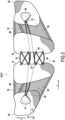
- FIG. 3 represents a medical device 20 according to the invention intended to support at least one area of the body.
- it is a lumbar support belt 21.
- Said medical device 20 comprises a left lateral part 22 and a right lateral part 23 intended, in operation and therefore when worn, to cover respectively the left flank and at least one left posterior dorsal portion, and the right flank and at least one right posterior dorsal portion of the wearer.
- the medical device 20 comprises a first end 24 and a second end 25 provided respectively with a first attachment member and a second attachment member, said first and second attachment members being able to cooperate to allow the lumbar support belt 21 to be closed on the wearer's trunk.
- Said first and second attachment members being for example respectively attachment hooks and a textile having attachment loops.
- Each lateral part 22, 23 of the device 20 respectively comprises a textile panel 26, 27 according to the invention.
- Each textile panel 26, 27 respectively comprises two woven strips 28, 29 each corresponding to the woven strip 1 shown in Figure 1 .
- the woven strips 28,29 are superimposed and arranged together so that the warp direction C1 of the woven strip 28 forms an angle alpha of the order of 45° with the warp direction C2 of the woven strip 29.
- Each textile panel, 28 and 29, has in the longitudinal direction an elongation greater than or equal to 30% under the application of a force greater than or equal to 700 cN/cm, in particular between 1400 cN/cm and 2000 cN/cm. It is therefore necessary to apply a force between 1400 cN/cm and 2000 cN/cm in the longitudinal direction of said textile panels 28, 29 to obtain an elongation of at least 30% in this direction L.
- the medical device 20 further comprises a mechanical clamping device 30 for multiplying the manual application force, arranged between the left 22 and right 23 lateral portions.
- this multiplying clamping device 30 comprises first 31 and second 32 lateral portions each comprising several eyelets 33, 34, in particular four eyelets, for the passage of two elongate elements 35, 36, such as cords.
- the eyelets 33 and the eyelets 34 respectively of the first 31 and second 32 lateral portions are opposite each other so as to form multiple returns of the elongate elements 35, 36 multiplying the application force.
- Two gripping members 37, 38 are secured via the elongated elements 35, 36 to said mechanical clamping device 30 and can be actuated by the installer to place the lumbar support belt 21 on his back and tighten the latter so as to make said first and second attachment members cooperate together for closing said medical device 20.
- the patient places the lumbar support belt 21 on his torso, actuates the multiplier tightening device 30 by pulling on the handles 37, 38 so as to press and tighten the belt 21 against his back, then makes the first and second fastening members cooperate to secure the belt 21.
Landscapes
- Health & Medical Sciences (AREA)
- Engineering & Computer Science (AREA)
- Heart & Thoracic Surgery (AREA)
- Nursing (AREA)
- Orthopedic Medicine & Surgery (AREA)
- Biomedical Technology (AREA)
- Vascular Medicine (AREA)
- Life Sciences & Earth Sciences (AREA)
- Animal Behavior & Ethology (AREA)
- General Health & Medical Sciences (AREA)
- Public Health (AREA)
- Veterinary Medicine (AREA)
- Textile Engineering (AREA)
- Mechanical Engineering (AREA)
- Woven Fabrics (AREA)
Claims (10)
- Medizinische Vorrichtung (20), die dazu vorgesehen ist, mindestens einen Bereich des Körpers zu unterstützen, insbesondere Knie- oder Sprunggelenkorthese, Stützgürtel (21) oder Stützband, umfassend mindestens eine Textilbahn (26, 27), die eine Längsrichtung (L) und eine Querrichtung (T) aufweist und derart eingerichtet ist, dass sie den zu unterstützenden Bereich des Körpers ganz oder teilweise umgibt, dadurch gekennzeichnet, dass:- die Textilbahn mehrere gewebte Textilbänder (1, 28, 29) umfasst, die zumindest teilweise überlagert sind,- die gewebten Bänder (1, 28, 29) jeweils eine Kettrichtung (C) und eine Schussrichtung (t) aufweisen und jeweils Schussfäden (2), erste elastische Kettfäden (3), von denen ein oder mehrere erste elastische Kettfäden (3) ein oder mehrere Monofilamentfäden aus Elasthan oder aus Elastodien ist/sind, die einen elastischen Kern ausbilden, der mit einem oder mehreren Deckfäden umwunden oder bedeckt ist, zweite nichtelastische Kettfäden (4) und dritte Kettfäden (5), wobei die ersten Kettfäden (3) und die zweiten Kettfäden (4) gemäß einer "Dreherbindung" gewebt sind, wobei die zweiten Kettfäden (4) Dreherfäden ausbilden, umfassen.- die Kett- und die Schussrichtung der gewebten Bänder zueinander parallel sind oder die Kett- oder Schussrichtung eines gegebenen gewebten Bandes gemäß einem Winkel alpha von größer als 0° und kleiner als 90° in Bezug auf die Kett- oder Schussrichtung eines anderen gewebten Bandes angeordnet ist,- dadurch, dass die Textilbahn (26, 27) in der Längsrichtung (L) elastisch ist und in der Längsrichtung (L), um eine Dehnung gleich 30 % zu erlangen, eine Kraft aufweist, die größer oder gleich 500 cN/cm ist,- dadurch, dass die Anzahl von Schussfäden pro Zentimeter in jedem der gewebten Bänder kleiner oder gleich 25 ist,- dadurch, dass mindestens einer der Schussfäden (2) eine Anzahl von Filamenten umfasst, die größer oder gleich 1 und kleiner oder gleich 5 ist, wobei jedes Filament einen Durchmesser größer oder gleich 0,10 mm aufweist,und dadurch, dass die zweiten Kettfäden (4) eine Umschlingung zur Einführung eines Schussfadens (2) ausführen.
- Vorrichtung (20) nach Anspruch 1, dadurch gekennzeichnet, dass sie eine Spannvorrichtung (30), welche die manuelle Anlegekraft der mindestens einen Textilbahn (26, 27) vervielfacht, insbesondere eine mechanische Spannvorrichtung mit Draht/Drähten (30) und/oder mit Rolle(n), umfasst.
- Vorrichtung (20) nach einem der Ansprüche 1 und 2, dadurch gekennzeichnet, dass der mindestens eine der ersten Kettfäden (3) mit mindestens einem ersten Deckfaden bedeckt ist.
- Vorrichtung (20) nach einem der Ansprüche 1 bis 3, dadurch gekennzeichnet, dass der mindestens eine der ersten elastischen Kettfäden (3), der gegebenenfalls mit mindestens einem ersten Deckfaden bedeckt ist, eine Bruchdehnung kleiner oder gleich 150 % aufweist.
- Vorrichtung (20) nach einem der Ansprüche 1 bis 4, dadurch gekennzeichnet, dass der mindestens eine der Schussfäden (2) eine Anzahl von Filamenten von größer oder gleich 1 und kleiner oder gleich 3 umfasst, wobei jedes Filament bevorzugt einen Durchmesser größer oder gleich 0,1 mm aufweist.
- Vorrichtung nach einem der Ansprüche 1 bis 5, dadurch gekennzeichnet, dass das gewebte Band (1) oder jedes der gewebten Bänder einen Wechsel von gefüllten Stegen (6) und durchbrochenen Stegen (7) umfasst, wobei jeder der gefüllten (6) und durchbrochenen (7) Stege eine Längsrichtung (I) aufweist, die der Kettrichtung (C) des gewebten Bandes (1) entspricht, wobei die gefüllten Stege (6) gemäß jeder ihrer Längskanten (8) mindestens einen ersten Kettfaden (3) und einen zweiten Kettfaden (4) umfassen, die gemäß einer Dreherbindung zusammengefügt sind.
- Vorrichtung nach Anspruch 6, dadurch gekennzeichnet, dass die durchbrochenen Stege (7) aus Schussfäden (2) gebildet sind.
- Vorrichtung (20) nach einem der Ansprüche 1 bis 7, dadurch gekennzeichnet, dass die Textilbahn (26, 27) in der Längsrichtung (L), um eine Dehnung gleich 30 % zu erlangen, eine Kraft aufweist, die größer oder gleich 700 cN/cm, bevorzugt größer oder gleich 1000 cN/cm, und kleiner oder gleich 2500 cN/cm ist.
- Verfahren zur Herstellung einer Vorrichtung (20) nach einem der Ansprüche 1 bis 8, dadurch gekennzeichnet, dass es die folgenden Schritte umfasst:- einen ersten Schritt des Webens mehrerer gewebter Textilbänder (28, 29), wobei jedes Textilband (1, 28, 29) gewebt wird mit:ersten elastischen Kettfäden (3), von denen ein oder mehrere erste elastische Kettfäden (3) ein oder mehrere Monofilamentfäden aus Elasthan oder aus Elastodien ist/sind, die einen elastischen Kern ausbilden, der mit einem oder mehreren Deckfäden umwunden oder bedeckt ist,zweiten nichtelastischen Kettfäden (4), dritten Kettfäden (5) und Schussfäden (2),wobei die ersten Kettfäden (3) und die zweiten Kettfäden (4) gemäß einer Dreherbindung derart gewebt werden, sodass die zweiten Kettfäden (4) Dreherfäden ausbilden,wobei die Anzahl von Schussfäden pro Zentimeter in jedem der gewebten Bänder kleiner oder gleich 25 ist,- wobei der mindestens eine der Schussfäden (2) einen Faden umfasst, der eine Anzahl von Filamenten größer oder gleich 1 und kleiner oder gleich 5 umfasst, wobei jedes Filament einen Durchmesser größer oder gleich 0,10 mm aufweist,- einen Schritt des Aufbringens einer Spannung (daN) auf den mindestens einen der ersten elastischen Kettfäden (3) derart, dass sich der mindestens erste elastische Kettfaden (3) während des ersten Schritts dehnt, wobei der Schritt des Aufbringens eine Anzahl von Umschlingungen der zweiten Kettfäden (4) gleich eins zur Einführung eines Schussfadens (2) umfasst,- einen Schritt des Ausbildens einer Textilbahn (26, 27), die eine Längsrichtung (L) und eine Querrichtung (T) aufweist, umfassend mehrere überlagerte gewebte Textilbänder (28, 29) derart, dass die Kett- und die Schussrichtung der gewebten Bänder zueinander parallel sind, oder derart, dass die Kett- oder Schussrichtung eines gegebenen gewebten Bandes gemäß einem Winkel alpha von größer als 0° und kleiner als 90° in Bezug auf die Kett- oder Schussrichtung eines anderen gewebten Bandes angeordnet ist, wobei die Bahn in der Längsrichtung (L), um eine Dehnung gleich 30 % zu erlangen, eine Kraft aufweist, die größer oder gleich 500 cN/cm ist.
- Verfahren zur Herstellung nach Anspruch 9, dadurch gekennzeichnet, dass der Schritt des Spannens darin besteht, eine Spannung auf den mindestens einen der ersten elastischen Kettfäden (3) mithilfe einer oder mehrerer Vorrichtungen auszuüben, die ausgewählt ist/sind aus der Gruppe bestehend aus den folgenden Vorrichtungen: der mindestens eine der ersten elastischen Kettfäden (3) wird mit mindestens einem ersten Deckfaden bedeckt, der eine Anzahl von Umschlingungen/Meter von größer oder gleich 720 Umschlingungen/m aufweist, und/oder einer auf den mindestens einen der ersten elastischen Kettfäden (3) ausgeübten Spannung größer oder gleich 10 cN.
Applications Claiming Priority (2)
| Application Number | Priority Date | Filing Date | Title |
|---|---|---|---|
| FR1562883A FR3045315B1 (fr) | 2015-12-21 | 2015-12-21 | Dispositif medical destine a soutenir au moins une zone du corps |
| PCT/FR2016/053610 WO2017109410A1 (fr) | 2015-12-21 | 2016-12-21 | Dispositif medical destine a soutenir au moins une zone du corps |
Publications (2)
| Publication Number | Publication Date |
|---|---|
| EP3393408A1 EP3393408A1 (de) | 2018-10-31 |
| EP3393408B1 true EP3393408B1 (de) | 2025-04-23 |
Family
ID=55451381
Family Applications (1)
| Application Number | Title | Priority Date | Filing Date |
|---|---|---|---|
| EP16831501.8A Active EP3393408B1 (de) | 2015-12-21 | 2016-12-21 | Medizinische vorrichtung zur unterstützung von mindestens eines bereichs des körpers |
Country Status (4)
| Country | Link |
|---|---|
| US (1) | US12127964B2 (de) |
| EP (1) | EP3393408B1 (de) |
| FR (1) | FR3045315B1 (de) |
| WO (1) | WO2017109410A1 (de) |
Families Citing this family (5)
| Publication number | Priority date | Publication date | Assignee | Title |
|---|---|---|---|---|
| GB2552009B (en) * | 2016-07-06 | 2022-05-04 | The Spinecorporation Ltd | A brace and a method of fitting a brace |
| FR3089407B1 (fr) * | 2018-12-05 | 2020-12-18 | Thuasne | Ceinture orthopédique avec éléments de préhension |
| WO2021163151A1 (en) * | 2020-02-12 | 2021-08-19 | Djo, Llc | Lumbar-supporting back-bracing apparatus and methods |
| CN218999629U (zh) * | 2022-11-21 | 2023-05-12 | 东莞市福顺体育运动用品有限公司 | 一种新型旋钮调节松紧度的腰带 |
| US20250354306A1 (en) * | 2024-05-16 | 2025-11-20 | Sachin JHUNJHUNWALA | Method for producing elastic bands with recycled materials |
Citations (1)
| Publication number | Priority date | Publication date | Assignee | Title |
|---|---|---|---|---|
| US20140303537A1 (en) * | 2011-11-07 | 2014-10-09 | Gibaud | Kit for creating a lumbar support belt |
Family Cites Families (11)
| Publication number | Priority date | Publication date | Assignee | Title |
|---|---|---|---|---|
| JPS5028536B1 (de) * | 1970-05-18 | 1975-09-16 | ||
| IT966171B (it) * | 1971-10-04 | 1974-02-11 | Johnson & Johnson | Perfezionamento nei tessuti elasti ci a fasce per cinture e simili |
| FR2156436A1 (en) * | 1971-10-19 | 1973-06-01 | Roche Sa Samuel | Woven tape - including a central band of high transverse elasticity is formed with single weft yarn |
| US3920054A (en) * | 1974-05-29 | 1975-11-18 | Johnson & Johnson | Curvilinear waistband fabric |
| US3965944A (en) * | 1975-02-12 | 1976-06-29 | Johnson & Johnson | Lightweight narrow elastic fabric |
| US4207885A (en) * | 1979-03-07 | 1980-06-17 | Carolon Company | Woven elastic compression bandage |
| US5447498A (en) * | 1994-05-02 | 1995-09-05 | Watson; George W. | Mesh lumbar support belt |
| DE102005033720A1 (de) * | 2005-07-15 | 2007-01-18 | Karl Otto Braun Kg | In Kettrichtung längselastische Binde |
| FR2934151B1 (fr) * | 2008-07-25 | 2012-01-13 | Gibaud | Ceinture de contention |
| DE102014012654A1 (de) * | 2014-08-22 | 2016-02-25 | Bauerfeind Ag | Rücken- oder Beckenbandage |
| US10299955B2 (en) * | 2015-06-19 | 2019-05-28 | Aspen Medical Partners, Llc | Braces having inelastic and elastic materials |
-
2015
- 2015-12-21 FR FR1562883A patent/FR3045315B1/fr active Active
-
2016
- 2016-12-21 WO PCT/FR2016/053610 patent/WO2017109410A1/fr not_active Ceased
- 2016-12-21 US US16/064,523 patent/US12127964B2/en active Active
- 2016-12-21 EP EP16831501.8A patent/EP3393408B1/de active Active
Patent Citations (1)
| Publication number | Priority date | Publication date | Assignee | Title |
|---|---|---|---|---|
| US20140303537A1 (en) * | 2011-11-07 | 2014-10-09 | Gibaud | Kit for creating a lumbar support belt |
Also Published As
| Publication number | Publication date |
|---|---|
| EP3393408A1 (de) | 2018-10-31 |
| US12127964B2 (en) | 2024-10-29 |
| FR3045315A1 (fr) | 2017-06-23 |
| WO2017109410A1 (fr) | 2017-06-29 |
| FR3045315B1 (fr) | 2020-05-15 |
| US20190021895A1 (en) | 2019-01-24 |
Similar Documents
| Publication | Publication Date | Title |
|---|---|---|
| WO2017109410A1 (fr) | Dispositif medical destine a soutenir au moins une zone du corps | |
| CA2717515C (fr) | Orthese de compression veineuse elastique a mise en place facilitee | |
| JP6047557B2 (ja) | 人間または動物の身体に適用するための圧迫包帯 | |
| US20090099497A1 (en) | Bandage With Lengthwise Elasticity In Warp Direction | |
| US20060253058A1 (en) | Weft-inserted elastic adhesive bandage and method | |
| CA2521954C (fr) | Article ou sous-article de contention | |
| EP1122346B1 (de) | Elastisches Gewebe für Kompressionsbandage, insbesondere Venöse | |
| JP2009268482A (ja) | 皮膚貼着用伸縮テープ基材 | |
| EP1061165B1 (de) | Dehnbares Frottiergewebe | |
| FR2724186A1 (fr) | Procede de fabrication d'un support textile composite destine au renfort d'une ceinture et support textile composite ainsi obtenu | |
| EP4366670B1 (de) | Selbstsichernder kompressionsstreifen | |
| EP3716930B1 (de) | Körperkompressionsvorrichtung mit klettverschluss | |
| EP3696305B1 (de) | Textilgewebe mit kontollierter elastizität zur herstellung von bekleidungs-, unterbekleidungs-, orthesen- und sitzelementen | |
| EP3318141B1 (de) | Textilartikel in form eines luftdurchlässigen textilbandes, das durch wirken oder weben hergestellt wird und dafür geeignet ist, den oberen teil eines strumpfs oder einer socke zu bilden | |
| EP2885988B1 (de) | Formender Bekleidungsartikel | |
| WO2020234362A1 (fr) | Bande de compression comprenant une couche de capitonage | |
| CH347794A (fr) | Tissu élastique résistant à la tendance au glissement et procédé pour sa fabrication | |
| FR3020568A1 (fr) | Procede de fabrication d'un article de contention tel qu'un bas medical de compression et article de contention obtenu selon ledit procede | |
| BE559478A (de) | ||
| JP2006225797A (ja) | 複合撚糸およびそれを用いた織編物 | |
| RO127872B1 (ro) | Pansament elastic pentru ortopedie şi afecţiuni circulatorii, şi procedeu de realizare a acestuia | |
| ZA200600194B (en) | Weft-inserted elastic adhesive bandage and method | |
| FR2792657A1 (fr) | Procede et dispositif de fabrication d'une bande de contention, bande correspondante et son utilisation | |
| BE348582A (de) |
Legal Events
| Date | Code | Title | Description |
|---|---|---|---|
| STAA | Information on the status of an ep patent application or granted ep patent |
Free format text: STATUS: UNKNOWN |
|
| STAA | Information on the status of an ep patent application or granted ep patent |
Free format text: STATUS: THE INTERNATIONAL PUBLICATION HAS BEEN MADE |
|
| PUAI | Public reference made under article 153(3) epc to a published international application that has entered the european phase |
Free format text: ORIGINAL CODE: 0009012 |
|
| STAA | Information on the status of an ep patent application or granted ep patent |
Free format text: STATUS: REQUEST FOR EXAMINATION WAS MADE |
|
| 17P | Request for examination filed |
Effective date: 20180523 |
|
| AK | Designated contracting states |
Kind code of ref document: A1 Designated state(s): AL AT BE BG CH CY CZ DE DK EE ES FI FR GB GR HR HU IE IS IT LI LT LU LV MC MK MT NL NO PL PT RO RS SE SI SK SM TR |
|
| AX | Request for extension of the european patent |
Extension state: BA ME |
|
| RIN1 | Information on inventor provided before grant (corrected) |
Inventor name: DE MONCUIT, HENRI Inventor name: BREUIL, LAURENT |
|
| DAV | Request for validation of the european patent (deleted) | ||
| DAX | Request for extension of the european patent (deleted) | ||
| STAA | Information on the status of an ep patent application or granted ep patent |
Free format text: STATUS: EXAMINATION IS IN PROGRESS |
|
| 17Q | First examination report despatched |
Effective date: 20210705 |
|
| GRAP | Despatch of communication of intention to grant a patent |
Free format text: ORIGINAL CODE: EPIDOSNIGR1 |
|
| STAA | Information on the status of an ep patent application or granted ep patent |
Free format text: STATUS: GRANT OF PATENT IS INTENDED |
|
| RIC1 | Information provided on ipc code assigned before grant |
Ipc: D03D 19/00 20060101ALI20240614BHEP Ipc: D02G 3/32 20060101ALI20240614BHEP Ipc: D03D 15/56 20210101ALI20240614BHEP Ipc: A61F 5/02 20060101ALI20240614BHEP Ipc: A61F 5/01 20060101AFI20240614BHEP |
|
| INTG | Intention to grant announced |
Effective date: 20240702 |
|
| RAP3 | Party data changed (applicant data changed or rights of an application transferred) |
Owner name: THUASNE |
|
| GRAS | Grant fee paid |
Free format text: ORIGINAL CODE: EPIDOSNIGR3 |
|
| GRAJ | Information related to disapproval of communication of intention to grant by the applicant or resumption of examination proceedings by the epo deleted |
Free format text: ORIGINAL CODE: EPIDOSDIGR1 |
|
| GRAL | Information related to payment of fee for publishing/printing deleted |
Free format text: ORIGINAL CODE: EPIDOSDIGR3 |
|
| STAA | Information on the status of an ep patent application or granted ep patent |
Free format text: STATUS: EXAMINATION IS IN PROGRESS |
|
| GRAP | Despatch of communication of intention to grant a patent |
Free format text: ORIGINAL CODE: EPIDOSNIGR1 |
|
| STAA | Information on the status of an ep patent application or granted ep patent |
Free format text: STATUS: GRANT OF PATENT IS INTENDED |
|
| INTC | Intention to grant announced (deleted) | ||
| INTG | Intention to grant announced |
Effective date: 20241120 |
|
| GRAA | (expected) grant |
Free format text: ORIGINAL CODE: 0009210 |
|
| STAA | Information on the status of an ep patent application or granted ep patent |
Free format text: STATUS: THE PATENT HAS BEEN GRANTED |
|
| AK | Designated contracting states |
Kind code of ref document: B1 Designated state(s): AL AT BE BG CH CY CZ DE DK EE ES FI FR GB GR HR HU IE IS IT LI LT LU LV MC MK MT NL NO PL PT RO RS SE SI SK SM TR |
|
| REG | Reference to a national code |
Ref country code: GB Ref legal event code: FG4D Free format text: NOT ENGLISH |
|
| REG | Reference to a national code |
Ref country code: CH Ref legal event code: EP |
|
| REG | Reference to a national code |
Ref country code: DE Ref legal event code: R096 Ref document number: 602016092008 Country of ref document: DE |
|
| REG | Reference to a national code |
Ref country code: IE Ref legal event code: FG4D Free format text: LANGUAGE OF EP DOCUMENT: FRENCH |
|
| REG | Reference to a national code |
Ref country code: NL Ref legal event code: MP Effective date: 20250423 |
|
| PG25 | Lapsed in a contracting state [announced via postgrant information from national office to epo] |
Ref country code: NL Free format text: LAPSE BECAUSE OF FAILURE TO SUBMIT A TRANSLATION OF THE DESCRIPTION OR TO PAY THE FEE WITHIN THE PRESCRIBED TIME-LIMIT Effective date: 20250423 |
|
| REG | Reference to a national code |
Ref country code: AT Ref legal event code: MK05 Ref document number: 1787093 Country of ref document: AT Kind code of ref document: T Effective date: 20250423 |
|
| PG25 | Lapsed in a contracting state [announced via postgrant information from national office to epo] |
Ref country code: PT Free format text: LAPSE BECAUSE OF FAILURE TO SUBMIT A TRANSLATION OF THE DESCRIPTION OR TO PAY THE FEE WITHIN THE PRESCRIBED TIME-LIMIT Effective date: 20250825 Ref country code: ES Free format text: LAPSE BECAUSE OF FAILURE TO SUBMIT A TRANSLATION OF THE DESCRIPTION OR TO PAY THE FEE WITHIN THE PRESCRIBED TIME-LIMIT Effective date: 20250423 Ref country code: FI Free format text: LAPSE BECAUSE OF FAILURE TO SUBMIT A TRANSLATION OF THE DESCRIPTION OR TO PAY THE FEE WITHIN THE PRESCRIBED TIME-LIMIT Effective date: 20250423 |
|
| REG | Reference to a national code |
Ref country code: LT Ref legal event code: MG9D |
|
| PG25 | Lapsed in a contracting state [announced via postgrant information from national office to epo] |
Ref country code: NO Free format text: LAPSE BECAUSE OF FAILURE TO SUBMIT A TRANSLATION OF THE DESCRIPTION OR TO PAY THE FEE WITHIN THE PRESCRIBED TIME-LIMIT Effective date: 20250723 Ref country code: GR Free format text: LAPSE BECAUSE OF FAILURE TO SUBMIT A TRANSLATION OF THE DESCRIPTION OR TO PAY THE FEE WITHIN THE PRESCRIBED TIME-LIMIT Effective date: 20250724 |
|
| PG25 | Lapsed in a contracting state [announced via postgrant information from national office to epo] |
Ref country code: PL Free format text: LAPSE BECAUSE OF FAILURE TO SUBMIT A TRANSLATION OF THE DESCRIPTION OR TO PAY THE FEE WITHIN THE PRESCRIBED TIME-LIMIT Effective date: 20250423 |
|
| PG25 | Lapsed in a contracting state [announced via postgrant information from national office to epo] |
Ref country code: BG Free format text: LAPSE BECAUSE OF FAILURE TO SUBMIT A TRANSLATION OF THE DESCRIPTION OR TO PAY THE FEE WITHIN THE PRESCRIBED TIME-LIMIT Effective date: 20250423 |
|
| PG25 | Lapsed in a contracting state [announced via postgrant information from national office to epo] |
Ref country code: HR Free format text: LAPSE BECAUSE OF FAILURE TO SUBMIT A TRANSLATION OF THE DESCRIPTION OR TO PAY THE FEE WITHIN THE PRESCRIBED TIME-LIMIT Effective date: 20250423 |
|
| PG25 | Lapsed in a contracting state [announced via postgrant information from national office to epo] |
Ref country code: AT Free format text: LAPSE BECAUSE OF FAILURE TO SUBMIT A TRANSLATION OF THE DESCRIPTION OR TO PAY THE FEE WITHIN THE PRESCRIBED TIME-LIMIT Effective date: 20250423 |
|
| PG25 | Lapsed in a contracting state [announced via postgrant information from national office to epo] |
Ref country code: RS Free format text: LAPSE BECAUSE OF FAILURE TO SUBMIT A TRANSLATION OF THE DESCRIPTION OR TO PAY THE FEE WITHIN THE PRESCRIBED TIME-LIMIT Effective date: 20250723 |
|
| PG25 | Lapsed in a contracting state [announced via postgrant information from national office to epo] |
Ref country code: IS Free format text: LAPSE BECAUSE OF FAILURE TO SUBMIT A TRANSLATION OF THE DESCRIPTION OR TO PAY THE FEE WITHIN THE PRESCRIBED TIME-LIMIT Effective date: 20250823 |
|
| PG25 | Lapsed in a contracting state [announced via postgrant information from national office to epo] |
Ref country code: LV Free format text: LAPSE BECAUSE OF FAILURE TO SUBMIT A TRANSLATION OF THE DESCRIPTION OR TO PAY THE FEE WITHIN THE PRESCRIBED TIME-LIMIT Effective date: 20250423 |
|
| PG25 | Lapsed in a contracting state [announced via postgrant information from national office to epo] |
Ref country code: SM Free format text: LAPSE BECAUSE OF FAILURE TO SUBMIT A TRANSLATION OF THE DESCRIPTION OR TO PAY THE FEE WITHIN THE PRESCRIBED TIME-LIMIT Effective date: 20250423 Ref country code: DK Free format text: LAPSE BECAUSE OF FAILURE TO SUBMIT A TRANSLATION OF THE DESCRIPTION OR TO PAY THE FEE WITHIN THE PRESCRIBED TIME-LIMIT Effective date: 20250423 |
|
| PGFP | Annual fee paid to national office [announced via postgrant information from national office to epo] |
Ref country code: FR Payment date: 20251218 Year of fee payment: 10 |
|
| PG25 | Lapsed in a contracting state [announced via postgrant information from national office to epo] |
Ref country code: CZ Free format text: LAPSE BECAUSE OF FAILURE TO SUBMIT A TRANSLATION OF THE DESCRIPTION OR TO PAY THE FEE WITHIN THE PRESCRIBED TIME-LIMIT Effective date: 20250423 |
|
| PG25 | Lapsed in a contracting state [announced via postgrant information from national office to epo] |
Ref country code: EE Free format text: LAPSE BECAUSE OF FAILURE TO SUBMIT A TRANSLATION OF THE DESCRIPTION OR TO PAY THE FEE WITHIN THE PRESCRIBED TIME-LIMIT Effective date: 20250423 |
|
| REG | Reference to a national code |
Ref country code: DE Ref legal event code: R097 Ref document number: 602016092008 Country of ref document: DE |
|
| PG25 | Lapsed in a contracting state [announced via postgrant information from national office to epo] |
Ref country code: RO Free format text: LAPSE BECAUSE OF FAILURE TO SUBMIT A TRANSLATION OF THE DESCRIPTION OR TO PAY THE FEE WITHIN THE PRESCRIBED TIME-LIMIT Effective date: 20250423 Ref country code: SK Free format text: LAPSE BECAUSE OF FAILURE TO SUBMIT A TRANSLATION OF THE DESCRIPTION OR TO PAY THE FEE WITHIN THE PRESCRIBED TIME-LIMIT Effective date: 20250423 |
|
| PG25 | Lapsed in a contracting state [announced via postgrant information from national office to epo] |
Ref country code: IT Free format text: LAPSE BECAUSE OF FAILURE TO SUBMIT A TRANSLATION OF THE DESCRIPTION OR TO PAY THE FEE WITHIN THE PRESCRIBED TIME-LIMIT Effective date: 20250423 |
|
| PLBE | No opposition filed within time limit |
Free format text: ORIGINAL CODE: 0009261 |
|
| STAA | Information on the status of an ep patent application or granted ep patent |
Free format text: STATUS: NO OPPOSITION FILED WITHIN TIME LIMIT |
|
| REG | Reference to a national code |
Ref country code: CH Ref legal event code: L10 Free format text: ST27 STATUS EVENT CODE: U-0-0-L10-L00 (AS PROVIDED BY THE NATIONAL OFFICE) Effective date: 20260304 |
|
| 26N | No opposition filed |
Effective date: 20260126 |
|
| PGFP | Annual fee paid to national office [announced via postgrant information from national office to epo] |
Ref country code: DE Payment date: 20251231 Year of fee payment: 10 |