EP3393199B1 - Datenübertragungsverfahren und -benutzergerät - Google Patents
Datenübertragungsverfahren und -benutzergerät Download PDFInfo
- Publication number
- EP3393199B1 EP3393199B1 EP16880323.7A EP16880323A EP3393199B1 EP 3393199 B1 EP3393199 B1 EP 3393199B1 EP 16880323 A EP16880323 A EP 16880323A EP 3393199 B1 EP3393199 B1 EP 3393199B1
- Authority
- EP
- European Patent Office
- Prior art keywords
- symbol
- time length
- frame structure
- type
- subframe
- Prior art date
- Legal status (The legal status is an assumption and is not a legal conclusion. Google has not performed a legal analysis and makes no representation as to the accuracy of the status listed.)
- Active
Links
- 230000005540 biological transmission Effects 0.000 title claims description 135
- 238000000034 method Methods 0.000 title claims description 47
- 238000005070 sampling Methods 0.000 claims description 191
- 239000013256 coordination polymer Substances 0.000 claims description 52
- 125000004122 cyclic group Chemical group 0.000 claims description 27
- 230000007774 longterm Effects 0.000 claims description 8
- 238000004891 communication Methods 0.000 description 19
- 238000010586 diagram Methods 0.000 description 18
- 238000012545 processing Methods 0.000 description 12
- 230000003247 decreasing effect Effects 0.000 description 6
- 230000006870 function Effects 0.000 description 6
- 238000013461 design Methods 0.000 description 5
- 238000006243 chemical reaction Methods 0.000 description 4
- 230000008878 coupling Effects 0.000 description 3
- 238000010168 coupling process Methods 0.000 description 3
- 238000005859 coupling reaction Methods 0.000 description 3
- 230000008569 process Effects 0.000 description 3
- 230000001413 cellular effect Effects 0.000 description 2
- 238000005516 engineering process Methods 0.000 description 2
- 238000007689 inspection Methods 0.000 description 2
- 238000013507 mapping Methods 0.000 description 2
- 238000012544 monitoring process Methods 0.000 description 2
- 230000003287 optical effect Effects 0.000 description 2
- 230000009466 transformation Effects 0.000 description 2
- 238000002558 medical inspection Methods 0.000 description 1
- 238000010295 mobile communication Methods 0.000 description 1
- 230000006855 networking Effects 0.000 description 1
- 230000003595 spectral effect Effects 0.000 description 1
- 238000001774 stimulated Raman spectroscopy Methods 0.000 description 1
Images


Classifications
-
- H—ELECTRICITY
- H04—ELECTRIC COMMUNICATION TECHNIQUE
- H04L—TRANSMISSION OF DIGITAL INFORMATION, e.g. TELEGRAPHIC COMMUNICATION
- H04L27/00—Modulated-carrier systems
- H04L27/26—Systems using multi-frequency codes
- H04L27/2601—Multicarrier modulation systems
- H04L27/2647—Arrangements specific to the receiver only
- H04L27/2655—Synchronisation arrangements
- H04L27/2666—Acquisition of further OFDM parameters, e.g. bandwidth, subcarrier spacing, or guard interval length
-
- H—ELECTRICITY
- H04—ELECTRIC COMMUNICATION TECHNIQUE
- H04L—TRANSMISSION OF DIGITAL INFORMATION, e.g. TELEGRAPHIC COMMUNICATION
- H04L27/00—Modulated-carrier systems
- H04L27/26—Systems using multi-frequency codes
- H04L27/2601—Multicarrier modulation systems
- H04L27/2602—Signal structure
- H04L27/26025—Numerology, i.e. varying one or more of symbol duration, subcarrier spacing, Fourier transform size, sampling rate or down-clocking
-
- H—ELECTRICITY
- H04—ELECTRIC COMMUNICATION TECHNIQUE
- H04L—TRANSMISSION OF DIGITAL INFORMATION, e.g. TELEGRAPHIC COMMUNICATION
- H04L27/00—Modulated-carrier systems
- H04L27/26—Systems using multi-frequency codes
-
- H—ELECTRICITY
- H04—ELECTRIC COMMUNICATION TECHNIQUE
- H04L—TRANSMISSION OF DIGITAL INFORMATION, e.g. TELEGRAPHIC COMMUNICATION
- H04L27/00—Modulated-carrier systems
- H04L27/26—Systems using multi-frequency codes
- H04L27/2601—Multicarrier modulation systems
- H04L27/2602—Signal structure
- H04L27/2605—Symbol extensions, e.g. Zero Tail, Unique Word [UW]
- H04L27/2607—Cyclic extensions
-
- H—ELECTRICITY
- H04—ELECTRIC COMMUNICATION TECHNIQUE
- H04L—TRANSMISSION OF DIGITAL INFORMATION, e.g. TELEGRAPHIC COMMUNICATION
- H04L5/00—Arrangements affording multiple use of the transmission path
- H04L5/0001—Arrangements for dividing the transmission path
- H04L5/0003—Two-dimensional division
- H04L5/0005—Time-frequency
- H04L5/0007—Time-frequency the frequencies being orthogonal, e.g. OFDM(A), DMT
-
- H—ELECTRICITY
- H04—ELECTRIC COMMUNICATION TECHNIQUE
- H04L—TRANSMISSION OF DIGITAL INFORMATION, e.g. TELEGRAPHIC COMMUNICATION
- H04L9/00—Cryptographic mechanisms or cryptographic arrangements for secret or secure communications; Network security protocols
- H04L9/40—Network security protocols
-
- H—ELECTRICITY
- H04—ELECTRIC COMMUNICATION TECHNIQUE
- H04W—WIRELESS COMMUNICATION NETWORKS
- H04W72/00—Local resource management
- H04W72/04—Wireless resource allocation
- H04W72/044—Wireless resource allocation based on the type of the allocated resource
- H04W72/0453—Resources in frequency domain, e.g. a carrier in FDMA
-
- H—ELECTRICITY
- H04—ELECTRIC COMMUNICATION TECHNIQUE
- H04L—TRANSMISSION OF DIGITAL INFORMATION, e.g. TELEGRAPHIC COMMUNICATION
- H04L27/00—Modulated-carrier systems
- H04L27/26—Systems using multi-frequency codes
- H04L27/2601—Multicarrier modulation systems
- H04L27/2602—Signal structure
- H04L27/2605—Symbol extensions, e.g. Zero Tail, Unique Word [UW]
Definitions
- the present invention relates to the communications field, and in particular, to a data transmission method and user equipment in the communications field.
- Machine type communication is also referred to as machine-to-machine communication (M2M) or Internet of Things (IOT), and will become an important application in the communications field in the future.
- Future Internet of Things communication may cover fields such as smart metering, medical inspection and monitoring, logistics inspection, industrial inspection and monitoring, vehicle networking, smart community, and wearable device communication.
- a typical cellular Internet of Things system is narrowband IOT (NB-IOT).
- An uplink system bandwidth and a downlink system bandwidth of the NB-IOT are generally 200 kHz, an operating bandwidth is 180 kHz, and each guard bandwidth on both sides is 10 kHz.
- An orthogonal frequency division multiplexing (OFDM) technology is used for downlink NB-IOT, and twelve subcarriers with a bandwidth of 15 kHz are multiplexed in a frequency domain.
- a single carrier frequency division multiple access (SC-FDMA) technology is used for uplink NB-IOT.
- SC-FDMA transmission is first performing DFT processing on a time-domain signal, mapping a processed signal onto a subcarrier of a corresponding frequency resource, and then modulating the signal in an OFDM modulation manner and sending a modulated signal.
- a peak to average power ratio (PAPR) of a signal of SC-FDMA transmission is lower, which better helps implement a radio frequency component on user equipment (UE) such as a mobile phone.
- UE user equipment
- the uplink NB-IOT can support two subcarrier spacings of 3.75 kHz and 15 kHz.
- the subcarrier spacing of 3.75 kHz is used, UE supports only single-tone transmission (single-tone transmission), that is, a bandwidth of a time-domain signal of the UE is not greater than 3.75 kHz, and after DFT conversion, only one subcarrier with a subcarrier spacing of 3.75 kHz and in the OFDM modulation manner is occupied.
- the subcarrier spacing of 15 kHz may support both single-tone transmission (single-tone transmission) and multi-tone transmission (multi-tone transmission).
- a signal bandwidth of a subcarrier with a subcarrier spacing of 3.75 kHz is only 1/4 of a bandwidth of a subcarrier with a subcarrier spacing of 15 kHz. Therefore, a power spectral density of a transmitted signal of the subcarrier with a subcarrier spacing of 3.75 kHz is four times that of the subcarrier with a subcarrier spacing of 15 kHz, and better anti-interference and anti-path loss performance are gained. Therefore, the subcarrier with a subcarrier spacing of 3.75 kHz is more applicable to UE with poor coverage, for example, UE on a cell edge and even in a basement.
- a 3.75 kHz uplink subcarrier is embedded and deployed in a bandwidth resource of legacy Long Term Evolution (LTE)
- LTE Long Term Evolution
- a suitable time unit needs to be defined to define a physical resource block.
- the time unit is referred to as a subframe.
- a sub frame time length and a subframe structure need to be defined to make transmission efficiency of the NB-IOT as high as possible. That is, as many uplink OFDM symbols as possible are transmitted in each subframe time length.
- a base station may configure a piece of information srs-SubframeConfig in cell-level system broadcast information, where the information indicates a subframe pattern (subframe Pattern) in which an SRS can be sent, and UE in the cell may send an SRS in only subframes indicated by the SRS subframe pattern.
- UE may send an SRS on only the last OFDM symbol of the indicated subframes, when a frame structure of the NB-IOT is being designed, such a factor may be considered, to avoid mutual interference between an OFDM symbol that is sent by an NB-IOT terminal and that has an uplink subcarrier spacing of 3.75 kHz and an SRS that may be sent by a legacy LTE terminal.
- EP 2151945A2 discloses wireless communication apparatus and wireless communication controlling method. To reduce the influence of Doppler shift, with the sub-carrier interval being widened in a high-frequency band, transmission timings for every frequency band are matched each other.
- the present invention provides a data transmission method, a subframe structure, and an apparatus, so that when an NB-IOT system is deployed in an LTE system in an embedded manner, and when an NB-IOT terminal is sending data, a channel resource of the legacy LTE system can be adequately utilized, and a conflict with a legacy LTE SRS can be avoided.
- the present invention provides a data transmission method, where the method includes: determining, by a first terminal, a frame structure in a time unit, where the frame structure indicates that N type-1 OFDM symbols and a guard period (GP) are included in the time unit, the GP in the frame structure is behind the type-1 OFDM symbols, a subcarrier spacing of each type-1 OFDM symbol is ⁇ f1, a time length of the GP is greater than or equal to a time length occupied by one type-2 OFDM symbol for Sounding Reference Signal, SRS, transmission, a subcarrier spacing of the type-2 OFDM symbol is ⁇ f2, ⁇ f1 is unequal to ⁇ f2, the type-2 OFDM symbol is the last symbol of a subframe for legacy Long Term Evolution, LTE, and N is a positive integer, wherein N is a maximum quantity of carried type-1 OFDM symbols in the time unit after the time length occupied by the type-2 OFDM symbol is subtracted, the first terminal is narrowband Internet of Things, NB-IOT,
- a first terminal determines a frame structure in a time unit, where the frame structure includes N type-1 orthogonal frequency division multiplexing OFDM symbols and a GP, and a length of the GP is greater than or equal to a time length occupied by one OFDM symbol with a subcarrier spacing of ⁇ f 2 . Therefore, when an NB-IOT system is deployed in an LTE system in an embedded manner, and when an NB-IOT terminal is sending data, a channel resource of the legacy LTE system can be adequately utilized, and a conflict with a legacy LTE SRS can be avoided.
- the present invention provides a frame structure, where the frame structure indicates that N type-1 orthogonal frequency division multiplexing OFDM symbols and a guard period GP are included in a time unit, a subcarrier spacing of each type-1 OFDM symbol is ⁇ f 1 , a time length of the GP is greater than or equal to a time length occupied by one type-2 OFDM symbol, a subcarrier spacing of the type-2 OFDM symbol is ⁇ f 2 , ⁇ f 1 is unequal to ⁇ f 2 , and N is a positive integer; and the type-1 OFDM symbols are sent according to the frame structure.
- a frame structure in a time unit is designed, where the frame structure includes N type-1 orthogonal frequency division multiplexing OFDM symbols and a GP, and a length of the GP is greater than or equal to a time length occupied by one OFDM symbol with a subcarrier spacing of ⁇ f 2 . Therefore, when an NB-IOT system is deployed in an LTE system in an embedded manner, and when an NB-IOT terminal is sending data, a channel resource of the legacy LTE system can be adequately utilized, and a conflict with a legacy LTE SRS can be avoided.
- the GP is used to prevent the sent type-1 OFDM symbols and a type-2 OFDM symbol sent by a second terminal from overlapping on a time-frequency resource.
- N is a maximum quantity of carried type-1 OFDM symbols in the time unit after the time occupied by one type-2 OFDM symbol is subtracted.
- both a time length occupied by a cyclic prefix (CP) of the type-1 OFDM symbol and a time length occupied by a CP of the type-2 OFDM symbol are greater than or equal to a preset threshold.
- the frame structure is a first frame structure, where the first frame structure includes seven type-1 OFDM symbols and the GP.
- the time length occupied by the GP there is one OFDM symbol, sent by the second terminal, with a subcarrier spacing of ⁇ f 2 , and a frequency resource corresponding to the OFDM symbol, sent by the second terminal, with a subcarrier spacing of ⁇ f 2 overlaps a frequency resource allocated to the first terminal in the time unit.
- the type-1 OFDM symbol when a sampling rate is 1.92 MHz, includes a symbol sampling point part and a CP part, where a time length of the symbol sampling point part is 512 T s , a time length of the CP part is 17 T s , a time length occupied by the type-1 OFDM symbol is 529 T s , and a time length of T s is a time length corresponding to each sampling point at the 1.92 MHz sampling rate; and the length of the GP is equal to a time length occupied by one type-2 OFDM symbol in a Long Term Evolution LTE system.
- the frame structure is a second frame structure, where the second frame structure includes three type-1 OFDM symbols and the GP.
- the three type-1 OFDM symbols are respectively a symbol 0, a symbol 1, and a symbol 2, where the symbol 0 includes a first symbol sampling point part and a first CP part, a time length of the first symbol sampling point part is 512 T s , a time length of the first CP part is 36 T s , a time length occupied by the symbol 0 is 548 T s , and a time length of T s is a time length corresponding to each sampling point at the 1.92 MHz sampling rate; the symbol 1 includes a second symbol sampling point part and a second CP part, a time length of the second symbol sampling point part is 512 T s , a time length of the second CP part is 37 T s , and a time length occupied by the symbol 1 is 549 T s ; the symbol 2 is the same as the symbol 0, or the symbol 2 is the same as the symbol 1; and the length of the GP is equal to a time length occupied by two
- the present invention provides user equipment, where the user equipment includes a processor and a transmitter.
- the processor is configured to determine a frame structure in a time unit, the GP in the frame structure is behind the type-1 OFDM symbols, where the frame structure indicates that N type-1 orthogonal frequency division multiplexing OFDM symbols and a guard period GP are included in the time unit, a subcarrier spacing of each type-1 OFDM symbol is ⁇ f 1 , a time length of the GP is greater than or equal to a time length occupied by one type-2 OFDM symbol for Sounding Reference Signal, SRS, transmission, a subcarrier spacing of the type-2 OFDM symbol is ⁇ f 2 , ⁇ f 1 is unequal to ⁇ f 2 , the type-2 OFDM symbol is the last symbol of a subframe for legacy Long Term Evolution, LTE, and N is a positive integer; wherein N is a maximum quantity of carried type-1 OFDM symbols in the time unit after the time length occupied by the type-2 OFDM symbol is subtracted, the
- a frame structure in a time unit is determined.
- the frame structure includes N type-1 OFDM symbols with a subcarrier spacing of ⁇ f 1 and a GP, and a length of the GP is greater than or equal to a time length occupied by one OFDM symbol with a subcarrier spacing of ⁇ f 2 . Therefore, when an NB-IOT system is deployed in an LTE system in an embedded manner, and when an NB-IOT terminal is sending data, a channel resource of the legacy LTE system can be adequately utilized, and a conflict with a legacy LTE SRS can be avoided.
- GSM Global System for Mobile Communications
- CDMA Code Division Multiple Access
- WCDMA Wideband Code Division Multiple Access
- GPRS general packet radio service
- LTE frequency division duplex FDD
- TDD LTE time division duplex
- UMTS Universal Mobile Telecommunications System
- WiMAX Worldwide Interoperability for Microwave Access
- a base station may be a base station (BTS) in GSM or CDMA, may be a base station (NodeB, "NB” for short) in WCDMA, or may be an evolved NodeB ("e-NB” or “e-NodeB” for short) in LTE. This is not limited in the present invention.
- UE may be referred to as a terminal, a mobile station (MS), or a mobile terminal.
- the UE may communicate with one or more core networks by using a radio access network (RAN).
- RAN radio access network
- the user equipment may be a mobile phone (also referred to as a "cellular" phone) or a computer with a mobile terminal.
- the user equipment may further be a portable, pocket-sized, handheld, computer built-in, or in-vehicle mobile apparatus, which exchanges voice and/or data with the radio access network.
- the embodiments of the present invention are described only by using an LTE system as an example, but the present invention is not limited thereto, and the method and the apparatus in the embodiments of the present invention may be further applied to another communications system.
- the embodiments of the present invention are also described only by using user equipment in the LTE system as an example, but the present invention is not limited thereto, and the method and the apparatus in the embodiments of the present invention may be further applied to a base station and user equipment in another communications system.
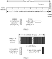
- FIG. 1 is a schematic diagram of a communications system.
- UE may communicate with a core network by using one or more base stations.
- UE 10a may communicate with a core network 12 by using a base station 110a on a radio access network 11a.
- UE 10b may communicate with the core network 12 by using the base station 110a on the radio access network 11a or by using a base station 11 0b on a radio access network 11b.
- UE 10c may communicate with the core network 12 by using the base station 110b on the radio access network 11b.
- the UE may communicate with a public switched telephone network (Public Switched Telephone Network, PSTN) 13, another network 14, or even the entire Internet 15.
- PSTN Public Switched Telephone Network
- FIG. 2 is a schematic diagram of an application scenario according to an embodiment of the present invention.
- a system with a subcarrier spacing of ⁇ f 2 may be an existing OFDM system, that is, an existing system.
- An OFDM system with a subcarrier spacing of ⁇ f 1 may be a new system.
- the new system is deployed for meeting a new service requirement.
- the new system and the existing system may have different subcarrier spacings, that is, ⁇ f 1 ⁇ f 2 .
- values of ⁇ f 1 and ⁇ f 2 are not limited in this embodiment of the present invention.
- ⁇ f 1 1/2 ⁇ f 2
- ⁇ f 1 1/4 ⁇ f 2
- the new system may be deployed in a time-frequency resource of the existing system, a bandwidth of the new system is W ⁇ f2 , and some system resources of the existing system are used in a manner of frequency division multiplexing (FDM) or a manner of time division multiplexing (TDM) and FDM.
- the existing system is a deployed OFDM system, and when the new system is being deployed, existing user equipment of the OFDM system with a subcarrier spacing of ⁇ f 2 has already been deployed and used on a live network.
- the existing user equipment may not know existence of the OFDM system with a subcarrier spacing of ⁇ f 1 . Therefore, an OFDM symbol with a subcarrier spacing of ⁇ f 2 may be sent in all resources or some resources of all resources in the entire bandwidth W ⁇ f2 of the existing system.
- a part of time is reserved as a GP in a particular location of each time unit, for avoiding interference with the OFDM symbol, sent by the existing user equipment of the existing system, with a subcarrier spacing of ⁇ f 2 .
- the signal may not overlap an OFDM symbol, of user equipment of the new system, with a subcarrier spacing of ⁇ f 1 , thereby avoiding mutual interference and impact.
- a sending and receiving structure of an OFDM system are generally implemented by using an inverse fast Fourier transformation (IFFT) processing module and a fast Fourier transformation (FFT) processing module.
- IFFT inverse fast Fourier transformation
- FFT fast Fourier transformation
- serial-to-parallel conversion is performed on a to-be-sent symbol sequence (optionally, sometimes a zero-adding operation is further required), several zeros are added to every X symbols output after the serial-to-parallel conversion, every X symbols are used as a group for IFFT processing, parallel-to-serial conversion is performed after X output symbols are obtained, and then, X symbol sampling points on a time domain are obtained.
- the OFDM modulation sending apparatus may insert a cyclic prefix including several sampling points (assuming that a quantity is Y) in front of the X symbol sampling points.
- the cyclic prefix is formed by repeating the last Y sampling points of the X symbol sampling points and inserting the last Y sampling points in front of the X symbol sampling points. Therefore, a final OFDM symbol corresponds to (X+Y) sampling points on the time domain, and a time corresponding to the OFDM symbol is a time length of (X+Y) ⁇ T s seconds, where T s is a reciprocal of the sampling rate S Hz.
- a time Y ⁇ T s corresponding to the cyclic prefix should be greater than a threshold Threshold CP , where the threshold is a length of multipath delay spread of a channel between a receiver and a sender, and is determined by a communication environment in which the receiver and the sender are located.
- SC-FDMA transmission is actually performing DFT processing on a time-domain signal, mapping a processed signal onto a subcarrier of a corresponding frequency resource, and then modulating the signal in an OFDM modulation manner and sending a modulated signal. Therefore, in the present invention, terms such as an "OFDM system” and an “OFDM symbol” are used uniformly for description. However, the content of the present invention is also applicable to a scenario of SC-FDMA transmission.
- an OFDM symbol with a subcarrier spacing of ⁇ f 1 may be referred to as a type-1 OFDM symbol
- an OFDM symbol with a subcarrier spacing of ⁇ f 2 may be referred to as a type-2 OFDM symbo1.
- FIG. 3 is a schematic diagram of a frame structure for data transmission according to an embodiment of the present invention.
- the frame structure corresponds to one time unit, and the frame structure in one time unit may include N OFDM symbols with a subcarrier spacing of ⁇ f 1 and a GP, where a length of the GP may be greater than or equal to a time length occupied by one OFDM symbol with a subcarrier spacing of ⁇ f 2 , ⁇ f 1 is unequal to ⁇ f 2 , and N is a positive integer.
- the time unit may be 1 ms, 2 ms, 4 ms, 5 ms, or the like.
- frame structure used in the present invention represents only a symbol structure, a symbol quantity, and a GP length in one time unit.
- the term represents a general concept rather than representing that the time unit corresponds to a length of one frame.
- One time unit in the present invention may correspond to a slot (Slot), a subframe (sub-frame), a frame (Frame), and the like.
- Frame structures corresponding to these time units may correspondingly refer to a slot structure, a subframe structure, and a frame structure. That is, although the term of frame structure is used in the present invention, the frame structure actually may also refer to a subframe structure, a slot structure, and the like in general.
- a remaining time may be a time occupied by a GP.
- a value of N is a maximum quantity of OFDM symbols with a subcarrier spacing of ⁇ f 1 that can be carried in a remaining time of the time unit T time-unit after the time that one OFDM symbol with a subcarrier spacing of ⁇ f 2 needs to occupy is subtracted.
- a value of N may be a greatest integer less than or equal to [ ⁇ f1 ⁇ ( T time-unit -T OFDM, ⁇ f2 )], where T OFDM, ⁇ f2 is the time length occupied by one OFDM symbol with a subcarrier spacing of ⁇ f 2 .
- One OFDM symbol with a subcarrier spacing of ⁇ f 1 may include FFT ⁇ f1 symbol sampling points and CP ⁇ f1 cyclic prefix (CP) sampling points.
- One OFDM symbol with a subcarrier spacing of ⁇ f 2 may include FFT ⁇ f2 symbol sampling points and CP ⁇ f2 cyclic prefix sampling points; a time length occupied by a cyclic prefix of the orthogonal frequency division multiplexing OFDM symbol with a subcarrier spacing of ⁇ f 1 is CP ⁇ f1 ⁇ Ts , and is not lower than a preset threshold (Threshold CP ).; A time length occupied by a cyclic prefix of the OFDM symbol with a subcarrier spacing of ⁇ f 2 is CP ⁇ f2 ⁇ Ts , and is not lower than the preset threshold (Threshold CP ).
- the GP in the frame structure may be behind or in the middle of the N OFDM symbols with a subcarrier spacing of ⁇ f 1 .
- the length of the GP in this embodiment of the present invention may be greater than or equal to a time length of the time length occupied by one OFDM symbol with a subcarrier spacing of ⁇ f 2 plus the Threshold CP , where ⁇ f 1 is unequal to ⁇ f 2 , and N is a positive integer.
- the frame structure includes N OFDM symbols with a subcarrier spacing of ⁇ f 1 and a GP, where a length of the GP is greater than or equal to a time length occupied by one OFDM symbol with a subcarrier spacing of ⁇ f 2 . Therefore, when an NB-IOT system is deployed in an LTE system in an embedded manner, and when NB-IOT user equipment is sending data, a channel resource of the legacy LTE system can be adequately utilized, and a conflict with a legacy LTE SRS can be avoided.
- the existing system may be an existing LTE system
- the subcarrier spacing ⁇ f 2 of the existing system may be 15 kHz
- the subcarrier spacing ⁇ f 1 of the new system may be 3.75 kHz.
- existing UE of the existing LTE system may send an SRS on the last symbol of OFDM symbols with a subcarrier spacing of 15 kHz in each 1 ms subframe.
- existing LTE user equipment may send an SRS over a full bandwidth in a time sharing manner according to the full bandwidth or according to a frequency hopping pattern. Therefore, when UE of the existing LTE system sends an SRS in a frequency resource of the new system, the SRS may conflict with an OFDM symbol, sent by UE of the new system, with a subcarrier spacing of 3.75 kHz, which causes mutual interference.
- a GP is reserved at the end of the frame structure, where a length of the GP is greater than or equal to a length of one OFDM symbol of the existing LTE system.
- the OFDM symbol with a subcarrier spacing of 3.75 kHz of the new system may not interfere with the SRS sent by the UE of the existing LTE system.
- the frame structure can ensure a maximum quantity of OFDM symbols, carried in each time unit, with a subcarrier spacing of 3.75 kHz, to ensure transmission efficiency of the new system.
- the "frame boundary" is used to align a boundary of a time unit of the new system with a boundary of a time unit of the existing system.
- the frame boundary of the new system and the frame boundary of the existing system keep aligned, which may represent that a boundary of a subframe (or a slot, or a frame) of the new system is aligned with a subframe boundary (or a slot boundary, or a frame boundary) of the existing system. That is, although the term of frame boundary is used in the present invention, the frame boundary actually may also refer to a subframe boundary, a slot boundary, and the like in general.
- a frame structure in a time unit of 2 ms may be referred to as a "2 ms subframe” for short
- a frame structure in a time unit of 1 ms may be referred to as a "1 ms subframe” for short
- a frame structure in a time unit of 5 ms may be referred to as a "5 ms subframe” for short.
- the 1 ms subframe or 2 ms subframe or 5 ms subframe may be uniformly used for expression subsequently, and no detailed description is provided.
- FIG. 4 is a schematic diagram of a frame structure of a 1 ms subframe of UE in a legacy LTE system.
- a symbol sampling rate in the frame structure is assumed to be 1.92 MHz, a quantity of points of an FFT operation is 128, and the frame structure of the 1 ms subframe may include twelve OFDM symbols with a CP length of 9 T s and a subcarrier spacing of 15 kHz, and two OFDM symbols with a CP length of 10 T s and a subcarrier spacing of 15 kHz.
- the frame structure, shown in FIG. 4 of the 1 ms subframe of the UE of the legacy LTE system cannot support an OFDM symbol with a subcarrier spacing of 3.75 kHz.
- the present invention is described by using an assumption of a 1.92 MHz sampling rate.
- different sampling rates may be used for a same signal.
- a time length T s corresponding to each corresponding sampling point may be proportionally reduced to 1/A of a time corresponding to each sampling symbol at the reference sampling rate, and a quantity of sampling points corresponding to the same symbol is multiplied to A times a quantity of sampling points at the reference sampling rate.
- a quantity of points of FFT processing corresponding to the OFDM symbol is also multiplied to A times a quantity of points of FFT processing at the reference sampling rate.
- the 1 ms subframe may include twelve OFDM symbols with a CP length of 9 T s and a subcarrier spacing of 15 kHz, and two OFDM symbols with a CP length of 10 T s and a subcarrier spacing of 15 kHz.
- the LTE 1 ms subframe may include twelve OFDM symbols with a CP length of (16 ⁇ 9) T s and a subcarrier spacing of 15 kHz, and two OFDM symbols with a CP length of (16 ⁇ 10) T s and a subcarrier spacing of 15 kHz. That is, different sampling rates correspond to different representation manners for a same frame structure and symbol structure.
- the quantity of sampling points is proportionally increased (or decreased), an absolute time of T s is proportionally decreased (or increased), and a time length of a finally represented symbol and a frame structure are consistent.
- Representations at different sampling rates are merely different representations for a frame structure, a symbol structure, and a GP length in a same time unit.
- the frame structure shown in FIG. 3 in this embodiment of the present invention may be applied to the application scenario shown in FIG. 2 .
- the new system corresponds to an NB-IOT system, and a subcarrier spacing ⁇ f 1 of the new system may be 3.75 kHz.
- the existing system corresponds to an existing LTE system, and a subcarrier spacing of the existing system may be 15 kHz.
- UE in the NB-IOT system may use SC-FDMA transmission with a subcarrier spacing of 3.75 kHz on an uplink.
- the frame structure may be a frame structure of a 2 ms subframe.
- the frame structure may be a first frame structure, and may include seven OFDM symbols with a subcarrier spacing of 3.75 kHz and a GP, where a length of the GP is greater than or equal to a time length occupied by one OFDM symbol with a subcarrier spacing of 15 kHz.
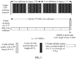
- a frame structure of a 2 ms subframe may be shown in FIG. 5 , where the frame structure of the 2 ms subframe shown in FIG. 5 may include seven OFDM symbols with a subcarrier spacing of 3.75 kHz and a GP located behind the seven OFDM symbols with a subcarrier spacing of 3.75 kHz, and a length of the GP is equal to a time length occupied by one OFDM symbol with a subcarrier spacing of 15 kHz.
- structure parameters of the frame structure of the 2 ms subframe shown in FIG. 5 may be shown in Table 1.
- a sampling rate corresponding to the structure parameters shown in Table 1 is 1.92 MHz.
- FFT ⁇ f1 represents a quantity of sampling points corresponding to a symbol sampling point part corresponding to each OFDM symbol with a subcarrier spacing of ⁇ f 1
- CP ⁇ f1 represents a quantity of sampling points corresponding to a cyclic prefix CP part of each OFDM symbol with a subcarrier spacing of ⁇ f 1 . It can be known from a definition of an OFDM symbol that one OFDM symbol with a subcarrier spacing of ⁇ f 1 includes CP ⁇ f1 CP sampling points and immediately following FFT ⁇ f1 symbol sampling points.
- one OFDM symbol with a subcarrier spacing of ⁇ f 1 totally includes (FFT ⁇ f1 +CP ⁇ f1 ) sampling points, and corresponds to a time length of (FFT ⁇ f 1 +CP ⁇ f 1 ) ⁇ T s .
- the parameters of the frame structure of the 2 ms subframe shown in Table 1 may include parameters of the OFDM symbol with a subcarrier spacing of 3.75 kHz and the GP, where the parameters may include a quantity of FFT points, a CP length of the OFDM symbol with a subcarrier spacing of 3.75 kHz, a symbol quantity of OFDM symbols with a subcarrier spacing of 3.75 kHz, a symbol length of the OFDM symbol with a subcarrier spacing of 3.75 kHz, a time length, and duration of the GP.
- the length of the GP is equal to the time length occupied by one OFDM symbol with a subcarrier spacing of 15 kHz in the existing LTE system, that is, a time length corresponding to (128+9) sampling points.
- structure parameters of the frame structure may be shown in Table 2.
- a sampling rate corresponding to the frame structure parameters shown in Table 2 is 1.92 MHz.
- FFT ⁇ f1 represents a quantity of sampling points corresponding to a symbol sampling point part corresponding to each OFDM symbol with a subcarrier spacing of ⁇ f 1
- C P ⁇ f1 represents a quantity of sampling points corresponding to a cyclic prefix CP part of each OFDM symbol with a subcarrier spacing of ⁇ f 1 . It can be known from a definition of an OFDM symbol that one OFDM symbol with a subcarrier spacing of ⁇ f 1 includes CP ⁇ f 1 CP sampling points and immediately following FFT ⁇ f1 symbol sampling points.
- one OFDM symbol with a subcarrier spacing of ⁇ f 1 totally includes (FFT ⁇ f1 +CP ⁇ f1 ) sampling points, and corresponds to a time length of (FFT ⁇ f 1 +CP ⁇ f 1 ) ⁇ T s .
- the parameters of the frame structure in a time unit of 2 ms shown in Table 2 may include parameters of the OFDM symbol with a subcarrier spacing of 3.75 kHz and the GP, where the parameters may include a quantity of FFT points, a CP length of the OFDM symbol with a subcarrier spacing of 3.75 kHz, a symbol quantity of OFDM symbols with a subcarrier spacing of 3.75 kHz, a symbol length of the OFDM symbol with a subcarrier spacing of 3.75 kHz, a time length of a frame, and duration of the GP.
- the length of the GP is (128+9+14) T s , which is greater than a time length of the time length occupied by one OFDM symbol with a subcarrier spacing of 15 kHz in the existing LTE system plus one Threshold CP .
- the frame structure of the 2 ms subframe in FIG. 5 of the present invention can be introduced to ensure that the SRS sent in the last subframe of every two subframes in the LTE system does not interfere with any NB-IOT OFDM symbol with a subcarrier spacing of 3.75 kHZ.
- a transmission mode of a channel sounding reference signal in a cell may be appropriately configured, for example, it is configured that only the second subframe of two subframes is a subframe in which the channel sounding reference signal can be sent, to avoid interference between an NB IOT terminal and an SRS of an existing LTE terminal.
- each subframe of the NB IOT there are seven OFDM symbol resources in each time unit of 2 ms, which is a maximum quantity of OFDM symbols with a subcarrier spacing of 3.75 kHz that can be carried in every 2 ms. Therefore, transmission efficiency of the NB IOT system is ensured. Compared with legacy LTE, resource efficiency of the NB IOT system is not decreased. In addition, a CP length of each OFDM symbol with a subcarrier spacing of 3.75 kHz is 17 T s , and greater delay spread can be tolerated.
- a frame structure in a time unit is designed, where the frame structure includes N OFDM symbols with a subcarrier spacing of ⁇ f 1 and a GP, and a length of the GP is greater than or equal to a time length occupied by one OFDM symbol with a subcarrier spacing of Af 2 . Therefore, when an NB-IOT system is deployed in an LTE system in an embedded manner, and when an NB-IOT terminal is sending data, a channel resource of the legacy LTE system can be adequately utilized, and a conflict with a legacy LTE SRS can be avoided.
- the NB-IOT system is embedded in the LTE system, and UE of the NB-IOT system may use the foregoing 2 ms subframe.
- the frame structure may be a second frame structure, and may include three OFDM symbols with a subcarrier spacing of 3.75 kHz and a GP, where a length of the GP is greater than or equal to a time length occupied by one OFDM symbol with a subcarrier spacing of 15 kHz.
- a frame structure of a 1 ms subframe in an embodiment of the present invention may be shown in FIG. 6 .
- the frame structure may be applied to the application scenario shown in FIG. 2 .
- the new system corresponds to an NB-IOT system, and a subcarrier spacing ⁇ f 1 of the new system may be 3.75 kHz.
- the existing system corresponds to an existing LTE system, and a subcarrier spacing ⁇ f 2 of the existing system may be 15 kHz.
- An NB-IOT terminal may use SC-FDMA transmission with a subcarrier spacing of 3.75 kHz on an uplink.
- the 1 ms subframe shown in FIG. 6 may be used.
- the frame structure of the 1 ms subframe in this embodiment of the present invention may include three OFDM symbol with a subcarrier spacing of 3.75 kHz and a GP located behind the three OFDM symbols with a subcarrier spacing of 3.75 kHz, where a length of the GP may be greater than or equal to a time length occupied by one OFDM symbol with a subcarrier spacing of 15 kHz.
- the frame structure of the 1 ms subframe may be shown in FIG. 6 , and the frame structure of the 1 ms subframe may include three OFDM symbols with a subcarrier spacing of 3.75 kHz and a GP located behind the three OFDM symbols with a subcarrier spacing of 3.75 kHz, where a length of the GP may be equal to a time length occupied by two OFDM symbols with a subcarrier spacing of 15 kHz.
- parameters of the frame structure of the 1 ms subframe shown in FIG. 6 may be shown in Table 3, and a sampling rate corresponding to the structure parameters shown in Table 3 is 1.92 MHz.
- FFT ⁇ f1 represents a quantity of sampling points corresponding to a symbol sampling point part corresponding to each OFDM symbol with a subcarrier spacing of ⁇ f 1
- CP ⁇ f1 represents a quantity of sampling points corresponding to a cyclic prefix CP part of each OFDM symbol with a subcarrier spacing of ⁇ f 1 . It can be known from a definition of an OFDM symbol that one OFDM symbol with a subcarrier spacing of ⁇ f 1 includes CP ⁇ f1 CP sampling points and immediately following FFT ⁇ f1 symbol sampling points.
- one OFDM symbol with a subcarrier spacing of ⁇ f 1 totally includes (FFT ⁇ f1 +CP ⁇ f1 ) sampling points, and corresponds to a time length of (FFT ⁇ f1 +CP ⁇ f1 ) ⁇ T s .
- the parameters of the 1 ms subframe shown in Table 3 may include an OFDM symbol 0 with a subcarrier spacing of 3.75 kHz, an OFDM symbol 1 with a subcarrier spacing of 3.75 kHz, an OFDM symbol 2 with a subcarrier spacing of 3.75 kHz, and a GP.
- the parameters for representing the foregoing OFDM symbols and the GP may include a quantity of FFT points, a CP length of the OFDM symbol 0 with a subcarrier spacing of 3.75 kHz, CP lengths of the OFDM symbol 1 with a subcarrier spacing of 3.75 kHz and the OFDM symbol 2 with a subcarrier spacing of 3.75 kHz, a symbol length of the OFDM symbol 0 with a subcarrier spacing of 3.75 kHz, symbol lengths of the OFDM symbol 1 and symbol 2 with a subcarrier spacing of 3.75 kHz, a time length, a time length of the GP, and so on.
- all symbol sampling point parts of the OFDM symbol 0 with a subcarrier spacing of 3.75 kHz and the symbol 1 and the symbol 2 correspond to 512 sampling points (a corresponding quantity of FFT ⁇ f1 points is 512), a quantity of CP sampling points of the OFDM symbol 0 with a subcarrier spacing of 3.75 kHz is 36, quantities of CP sampling points of the OFDM symbol 1 with a subcarrier spacing of 3.75 kHz and the OFDM symbol 2 with a subcarrier spacing of 3.75 kHz are 37, a first symbol length is 548 T s , a second symbol length is 549 T s , and the length of the GP is equal to a time length occupied by two OFDM symbols with a subcarrier spacing of 15 kHz in LTE.
- the zeroth OFDM symbol with a subcarrier spacing of 3.75 kHz includes 512 symbol sampling points and a cyclic prefix CP including 36 sampling points. Therefore, a symbol time length of the symbol 0 is 548 T s .
- the first or the second OFDM symbol with a subcarrier spacing of 3.75 kHz includes 512 symbol sampling points and a cyclic prefix CP including 37 sampling points. Therefore, both a symbol time length of the symbol 1 and a symbol time length of the symbol 2 are 549 T s .
- a GP length of each 1 ms subframe is equal to a time length occupied by two OFDM symbols with a subcarrier spacing of 15 kHz in LTE, that is, a time length corresponding to 2x(128+9) sampling points, that is, 2 ⁇ (128+9) ⁇ T s , where T s is a time length corresponding to each sampling point, and is a reciprocal of the sampling rate.
- FIG. 6 gives only an example of the embodiment of Table 3, and another arrangement manner of the OFDM symbols and the GP is not excluded in the present invention.
- the frame structure may be a third frame structure, and may include three OFDM symbols with a subcarrier spacing of 3.75 kHz and a GP, where a length of the GP is greater than or equal to a time length occupied by one OFDM symbol with a subcarrier spacing of 15 kHz.
- the frame structure is a fourth frame structure, where the fourth frame structure is formed by the second frame structure and/or the third frame structure.
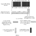
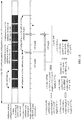
- FIG. 7 is a frame structure of a 1 ms subframe for transmitting data according to an embodiment of the present invention.
- the 1 ms subframe may be applied to the application scenario shown in FIG. 2 .
- the new system corresponds to an NB-IOT system, and a subcarrier spacing ⁇ f 1 of the new system may be 3.75 kHz.
- the existing system corresponds to an existing LTE system, and a subcarrier spacing ⁇ f 2 of the existing system may be 15 kHz.
- An NB-IOT terminal may use SC-FDMA transmission with a subcarrier spacing of 3.75 kHz on an uplink.
- the 1 ms subframe shown in FIG. 7 may be used.
- the frame structure of the 1 ms subframe in this embodiment of the present invention may include three OFDM symbols with a subcarrier spacing of 3.75 kHz and a GP, where a length of the GP may be a time length occupied by two OFDM symbols with a subcarrier spacing of 15 kHz, and the GP may be divided into a first GP and a second GP.
- the frame structure of the 1 ms subframe in the NB-IOT may be shown in FIG. 7
- the frame structure of the 1 ms subframe may include three OFDM symbols with a subcarrier spacing of 3.75 kHz, a first GP, and a second GP, where both the first GP and the second GP are a time length occupied by one OFDM symbol with a subcarrier spacing of 15 kHz, the first GP is located in front of the three OFDM symbols with a subcarrier spacing of 3.75 kHz, and the second GP is located behind the three OFDM symbols with a subcarrier spacing of 3.75 kHz.
- parameters of the 1 ms subframe shown in FIG. 7 may be shown in Table 4.
- a sampling rate corresponding to the parameters of the 1 ms subframe shown in Table 4 is 1.92 MHz.
- FFT ⁇ f1 represents a quantity of sampling points corresponding to a symbol sampling point part corresponding to each OFDM symbol with a subcarrier spacing of ⁇ f 1
- CP ⁇ f1 represents a quantity of sampling points corresponding to a cyclic prefix CP part of each OFDM symbol with a subcarrier spacing of ⁇ f 1 . It can be known from a definition of an OFDM symbol that one OFDM symbol with a subcarrier spacing of ⁇ f 1 includes CP ⁇ f1 CP sampling points and immediately following FFT ⁇ f1 symbol sampling points.
- one OFDM symbol with a subcarrier spacing of ⁇ f 1 totally includes (FFT ⁇ f1 +CP ⁇ f1 ) sampling points, and corresponds to a time length of (FFT ⁇ f1 +CP ⁇ f1 ) ⁇ T s .
- the frame structure of the 1 ms subframe may include an OFDM symbol 0 with a subcarrier spacing of 3.75 kHz, an OFDM symbol 1 with a subcarrier spacing of 3.75 kHz, an OFDM symbol 2 with a subcarrier spacing of 3.75 kHz, a first GP, and a second GP.
- the parameters for representing the foregoing OFDM symbols and the GPs may include a quantity of FFT points and a CP length of the OFDM symbol 0 with a subcarrier spacing of 3.75 kHz, quantities of FFT points and CP lengths of the OFDM symbol 1 with a subcarrier spacing of 3.75 kHz and the symbol 2 with a subcarrier spacing of 3.75 kHz, and time lengths of the first GP and the second GP.
- the sampling rate is 1920 kHz
- all symbol sampling point parts of the OFDM symbol 0 with a subcarrier spacing of 3.75 kHz and the symbol 1 and the symbol 2 correspond to 512 sampling points (a corresponding quantity of FFT ⁇ f1 points is 512)
- the CP length of the OFDM symbol 0 with a subcarrier spacing of 3.75 kHz is 37 T s
- the CP lengths of the OFDM symbol 1 with a subcarrier spacing of 3.75 kHz and the OFDM symbol 2 with a subcarrier spacing of 3.75 kHz are 36 T s
- the length of the symbol 0 is 549 T s
- the lengths of the symbol 1 and the symbol 2 are 548 T s
- the time length of the first GP is 138 T s
- the time length of the second GP is 137 T s .
- the zeroth OFDM symbol with a subcarrier spacing of 3.75 kHz includes 512 symbol sampling points and a cyclic prefix CP including 37 sampling points. Therefore, a symbol time length of the symbol 0 is 549 T s .
- the first or the second OFDM symbol with a subcarrier spacing of 3.75 kHz includes 512 symbol sampling points and a cyclic prefix including 36 sampling points. Therefore, both a symbol time length of the symbol 1 and a symbol time length of the symbol 2 are 548 T s .
- a length of a first GP of each 1 ms subframe is equal to a time length occupied by the first OFDM symbol with a subcarrier spacing of 15 kHz in each 1 ms subframe in LTE, that is, a time length corresponding to (128+10) sampling points, that is, (128+10) ⁇ T s .
- a length of a second GP of each 1 ms subframe is equal to a time length occupied by the last OFDM symbol with a subcarrier spacing of 15 kHz in each 1 ms subframe in the LTE, that is, a time length corresponding to (128+9) sampling points, that is, (128+9) ⁇ T s .
- T s is a time length corresponding to each sampling point, and is a reciprocal of the sampling rate.
- FIG. 7 gives only an example of the embodiment of Table 4, and another arrangement manner of the OFDM symbols and the GP is not excluded in the present invention.
- a 1 ms subframe is defined for an NB IOT system.
- a boundary of the 1 ms subframe is aligned with a boundary of an existing LTE subframe, it may be found that, when the NB-IOT system is deployed in an LTE system in an embedded manner, and an NB-IOT terminal sends a 3.75 kHz OFDM symbol, there is always no conflict with the last OFDM symbol, sent at the same time, with a subcarrier spacing of 15 kHz of each 1 ms subframe of an existing LTE terminal on a system frequency resource, thereby avoiding mutual interference with an SRS sent by the existing LTE terminal.
- a frame structure of the 1 ms subframe can carry three OFDM symbols with a subcarrier spacing of 3.75 kHz at most. Therefore, a design of the frame structure in a time unit of 1 ms is better.
- sequence numbers of the foregoing OFDM symbols with a subcarrier spacing of 3.75 kHz are only used to distinguish different symbols, and do not impose any limitation on implementation of the embodiments of the present invention.
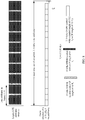
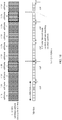
- FIG. 8 is a subframe structure for data transmission corresponding to another time unit according to an embodiment of the present invention.
- the subframe structure may be applied to the application scenario shown in FIG. 2 .
- the new system corresponds to an NB-IOT system, and a subcarrier spacing ⁇ f 1 of the new system may be 3.75 kHz.
- the existing system corresponds to an existing LTE system, and a subcarrier spacing ⁇ f 2 of the existing system may be 15 kHz.
- An NB-IOT terminal may use SC-FDMA transmission with a subcarrier spacing of 3.75 kHz on an uplink.
- the subframe structure shown in FIG. 8 may be used.
- the time unit may be 5 ms, the time unit may be defined as a slot or a subframe, and the subframe structure includes 18 OFDM symbols with a subcarrier spacing of 3.75 kHz and a GP located behind the 18 OFDM symbols with a subcarrier spacing of 3.75 kHz, where a length of the GP may be greater than or equal to a time length occupied by one OFDM symbol with a subcarrier spacing of 15 kHz.
- parameters of the subframe structure shown in FIG. 8 may be shown in Table 5.
- a sampling rate corresponding to the structure parameters shown in Table 5 is 1.92 MHz.
- FFT ⁇ f1 represents a quantity of sampling points corresponding to a symbol sampling point part corresponding to each OFDM symbol with a subcarrier spacing of ⁇ f 1
- CP ⁇ f1 represents a quantity of sampling points corresponding to a cyclic prefix CP part of each OFDM symbol with a subcarrier spacing of ⁇ f 1 . It can be known from a definition of an OFDM symbol that one OFDM symbol with a subcarrier spacing of ⁇ f 1 includes CP ⁇ f1 CP sampling points and immediately following FFT ⁇ f1 symbol sampling points.
- one OFDM symbol with a subcarrier spacing of ⁇ f 1 totally includes (FFT ⁇ f1 +CP ⁇ f1 ) sampling points, and corresponds to a time length of (FFT ⁇ f1 +CP ⁇ f1 ) ⁇ T s .
- the subframe structure in a time unit of 5 ms shown in Table 5 may include OFDM symbols 0 to 17 with a subcarrier spacing of 3.75 kHz and a GP.
- the parameters for representing the foregoing OFDM symbols and the GP may include a quantity of FFT points, CP lengths of the OFDM symbols 0 to 17 with a subcarrier spacing of 3.75 kHz, symbol lengths of the OFDM symbols 0 to 17 with a subcarrier spacing of 3.75 kHz, a subframe time length, a time length of the GP, and so on.
- a symbol sampling point part of each of the OFDM symbols 0 to 17 with a subcarrier spacing of 3.75 kHz corresponds to 512 sampling points (a corresponding quantity of FFT ⁇ f1 points is 512), a quantity of sampling points of each CP is 13, each symbol length is 525 T s , and the length of the GP is equal to (128+22) T s , which is greater than a time length occupied by one OFDM symbol with a subcarrier spacing of 15 kHz in LTE, where T s is a time length corresponding to each sampling point, and is a reciprocal of the sampling rate.
- FIG. 8 gives only an example of the embodiment of Table 5, and another arrangement manner of the OFDM symbols and the GP is not excluded in the present invention.
- FIG. 5 gives a frame structure of a 2 ms subframe in this embodiment of the present invention. It can be seen from the frame structure of the 2 ms subframe shown in FIG. 5 that, when a 2 ms subframe is used in an NB IOT system, and when a boundary of the 2 ms subframe of the NB IOT is aligned with a boundary of a 1 ms subframe in legacy LTE, a GP is set only at the end of the 2 ms subframe in a frame structure of the 2 ms subframe of the NB IOT, so as to ensure that only a channel sounding reference signal sent in the last subframe of every two subframes in the LTE system does not interfere with any one NB IOT OFDM symbol with a subcarrier spacing of 3.75 kHZ on a same frequency resource.
- a transmission mode (srs-SubframeConfig in LTE broadcast information) of a channel sounding reference signal in a cell needs to be appropriately configured, for example, it is configured that only the second subframe of two subframes is a subframe in which the channel sounding reference signal can be sent, to avoid interference between an NB IOT terminal and an SRS of an existing LTE terminal. That is, the frame structure of the 2 ms subframe in FIG. 5 has a limitation on a legacy LTE SRS configuration.
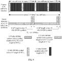
- a method for resolving the foregoing SRS configuration limitation is to introduce a frame structure of a 2 ms subframe shown in FIG. 9 of the present invention.
- the frame structure of the 2 ms subframe is designed by connecting two frame structures of a 1 ms subframe in FIG. 6 or FIG. 7 in series.
- a 2 ms subframe spliced by using two frame structures of the 1 ms subframe shown in FIG. 6 may be used as an example.
- the frame structure of the 2 ms subframe may be spliced by using two frame structure of the 1 ms subframe shown in FIG. 7 .
- the frame structure may also be combined by frame structures corresponding to a time unit of smaller granularity.
- a GP is introduced to a frame structure of each 1 ms subframe.
- only six OFDM symbols with a subcarrier spacing of 3.75 kHz can be carried in a 2 ms subframe of this type of frame structure.
- efficiency is decreased.
- a quantity of symbols with a subcarrier spacing of 3.75 kHZ that are carried in a frame structure of a 1 ms subframe is still a maximum quantity of symbols with a subcarrier spacing of 3.75 kHz that can be carried in the frame structure of a 1 ms subframe.
- two types of frame structures which are a subframe type 1 (for example, the 2 ms subframe structure in FIG. 5 ) and a subframe type 2 (for example, the 2 ms subframe structure in FIG. 9 ), are defined separately by using a 2 ms subframe as an example.
- Transmission efficiency of the subframe type 1 is high, and seven OFDM symbols with a subcarrier spacing of 3.75 kHz are transmitted in each 2 ms subframe.
- an SRS subframe pattern configuration of an LTE system that is deployed in a co-existence manner there is a certain limitation on an SRS subframe pattern configuration of an LTE system that is deployed in a co-existence manner.
- the subframe type 2 provides flexibility for the SRS subframe pattern configuration of the LTE system that is deployed in a co-existence manner, and may support the legacy LTE system that is deployed in a co-existence manner, to configure any 1 ms subframe as a subframe in which an SRS can be sent.
- transmission efficiency of the subframe type 2 is decreased, and only six OFDM symbols with a subcarrier spacing of 3.75 kHz can be transmitted in each 2 ms subframe.
- a base station broadcasts, in system broadcast information of an NB-IOT system, configuration information about a subframe transmission mode of the time unit.
- the configuration information indicates a subframe type transmission mode used when an NB-IOT terminal in a cell sends uplink information by using a subcarrier spacing of 3.75 kHz.
- a configuration of the subframe type transmission mode matches an SRS subframe pattern broadcast in the LTE system, so that when the first subframe of every two consecutive 1 ms LTE subframes may be used to send an SRS, the NB-IOT uses the subframe type 2 in a corresponding time. If the first subframe of every two consecutive 1 ms LTE subframes is not used to send an SRS, the NB-IOT uses the subframe type 1 in a corresponding time of two 1 ms.
- an NB-IOT base station may configure the subframe type 1 for the NB-IOT system as far as possible, to implement higher transmission efficiency, and when interference from an SRS that may be sent in the first 1 ms LTE subframe of every two 1 ms LTE subframes needs to be avoided, the NB-IOT base station may configure the subframe type 2 for the NB-IOT system as far as possible.
- a base station broadcasts, in system broadcast information of an NB-IOT system, configuration information about a subframe transmission mode.
- the configuration information indicates a 2 ms subframe type transmission sequence used when an NB-IOT terminal in a cell sends uplink information by using 3.75 kHz.
- a configuration of the subframe type transmission mode matches an SRS subframe pattern broadcast in the LTE system.
- subframe types of different types are defined by using a subframe in a time unit of 2 ms as an example, and an SRS subframe pattern configuration of the co-existing LTE system is flexibly supported by configuring the subframe type transmission mode.
- a subframe of another time unit such as 1 ms or 5 ms, a similar configuration manner may be used.
- the NB-IOT system when only the first subframe of every two consecutive 1 ms LTE subframes may be used to send an SRS, and the second subframe is not used to send an SRS, the NB-IOT system still uses the 2 ms subframe type 1 in a corresponding time; and only a cyclic shift of the subframe is introduced, so that the GP is aligned with the last LTE OFDM symbol of the first 1 ms LTE subframe.
- the NB-IOT system uses the 2 ms subframe type 2 in a corresponding time; if the first subframe of every two consecutive 1 ms LTE subframes is not used to send an SRS, the NB-IOT system uses the 2 ms subframe type 1 in a corresponding time of two 1 ms.
- an NB-IOT base station may configure the 2 ms subframe type 1 for the NB-IOT system as far as possible, to implement higher transmission efficiency; and when an SRS that may be sent in the first 1 ms LTE subframe of every two 1 ms LTE subframes needs to be avoided, the NB-IOT base station may configure the 2 ms subframe type 1 for the NB-IOT system as far as possible.
- subframe types of different types are defined by using a subframe in a time unit of 2 ms as an example, and an SRS subframe pattern configuration of the co-existing LTE system is flexibly supported by configuring the subframe type transmission mode.
- the subframe type transmission mode indicated by the configuration information and used when uplink information is sent by using 3.75 kHz, matches an SRS subframe pattern broadcast in the LTE system, so that transmission is performed according to the frame structure shown in FIG. 3 in each time unit of 2 ms (without loss of generality, it is assumed that each 2 ms is a slot).
- the configuration information of the subframe type transmission mode makes possible locations of as many LTE SRSs as possible overlap the GP in the frame structure shown in FIG. 3 .
- a transmission mode configuration of the LTE SRS for an LTE SRS location that cannot overlap the GP part of the frame structure corresponding to the 2 ms slot, user equipment that performs transmission by using a subcarrier spacing of 3.75 kHz does not perform uplink transmission on a 3. 75 kHz NB-IoT symbol overlapping with the LTE SRS, or does not send an uplink 3.75 kHz symbol on only a time location overlapping with the LTE SRS.
- An SRS configuration of an LTE frame structure Type 1 is shown in Table 6: Table 6 srs-SubframeConfig Binary Transmission cycle T SFC (subframe) Transmission offset ⁇ SFC (subframe) Subframe carrying an LTE SRS 0 0000 1 ⁇ 0 ⁇ ⁇ 0, 1, 2, 3, 4, 5, 6, 7, 8, 9 ⁇ 1 0001 2 ⁇ 0 ⁇ ⁇ 0, 2, 4, 6, 8 ⁇ 2 0010 2 ⁇ 1 ⁇ ⁇ 1, 3, 5, 7, 9 ⁇ 3 0011 5 ⁇ 0 ⁇ ⁇ 0, 5 ⁇ 4 0100 5 ⁇ 1 ⁇ ⁇ 1, 6 ⁇ 5 0101 5 ⁇ 2 ⁇ ⁇ 2, 7 ⁇ 6 0110 5 ⁇ 3 ⁇ ⁇ 3, 8 ⁇ 7 0111 5 ⁇ 0, 1 ⁇ ⁇ 0, 1, 5, 6 ⁇ 8 1000 5 ⁇ 2, 3 ⁇ ⁇ 2, 3, 7, 8 ⁇ 9 1001 10 ⁇ 0 ⁇ ⁇ 0 ⁇ 10 1010 10 ⁇ 1 ⁇ ⁇ 1 ⁇ 11 1011 10 ⁇ 2 ⁇ ⁇ 2 ⁇ 12 1100 10 ⁇ 3 ⁇ ⁇ 3 ⁇ 13 1101 10
- the superframe structure herein refers to a combination manner, on a time domain, of the first frame structure described above, and may be referred to as a second time unit superframe structure.
- the second time unit superframe structure includes N first frame structures, where N is a positive integer.
- N is a positive integer.
- a frame structure with a subcarrier spacing of 3.75 kHz in Table 7 is formed by the 2 ms subframe shown in FIG. 3 .
- an SRS transmission symbol overlaps an NB-IoT symbol, an NB-Slot symbol at the same moment is a blank symbol.
- the blank symbol herein refers to that no information, energy, or the like is transmitted on the symbol.
- an SRS is transmitted in each subframe or most subframes of an LTE radio frame.
- a start boundary of each first frame structure (NB-Slot) is aligned with a start boundary of an even-numbered LTE subframe, and the fourth symbol of each first frame structure (NB-Slot, narrowband slot) is a blank symbol and is not used for transmission.
- One NB-Slot herein is formed by the 2 ms subframe shown in FIG. 3 .
- srs-SubframeConfig when srs-SubframeConfig is configured as '1' on a network, that is, when an SRS transmission cycle is 2 ms, the SRS transmission cycle is consistent with a length of an NB-Slot, and a GP of the NB-Slot right overlaps an LTE SRS transmission symbol.
- An SRS is transmitted in an even-numbered subframe of an LTE radio frame. Therefore, a start boundary of a first frame structure (NB-Slot) is aligned with a start boundary of an even-numbered LTE subframe, and all symbols of each first frame structure (NB-Slot) are used for transmission.
- One NB-Slot herein is formed by the 2 ms subframe shown in FIG. 3 .
- srs-SubframeConfig when srs-SubframeConfig is configured as '2' on a network, that is, when an SRS transmission cycle is 2 ms, the SRS transmission cycle is consistent with a length of an NB-Slot, and a GP of a first frame structure (NB-Slot) right overlaps an LTE SRS transmission symbol.
- An SRS is transmitted in an odd-numbered subframe of an LTE radio frame. Therefore, a start boundary of a first frame structure (NB-Slot) is aligned with a start boundary of an odd-numbered LTE subframe, and all symbols of each first frame structure (NB-Slot) are used for transmission.
- One NB-Slot herein is formed by the 2 ms subframe shown in FIG. 3 .
- an SRS is transmitted in the first subframe and the sixth subframe of an LTE radio frame
- a start boundary of the second time unit superframe structure is aligned with a start boundary of the second subframe of the LTE radio frame
- a start boundary of each first frame structure (NB-Slot) is aligned with a start boundary of an odd-numbered LTE subframe
- the fourth symbol of the third first frame structure (NB-Slot) is a blank symbol and is not used for transmission.
- One first frame structure (NB-Slot) herein is formed by the 2 ms subframe shown in FIG. 3 .
- an SRS is transmitted in the first subframe of an LTE radio frame
- a start boundary of the second time unit superframe structure is aligned with a start boundary of the second subframe of the LTE radio frame
- a start boundary of each first frame structure (NB-Slot) is aligned with a start boundary of an odd-numbered LTE subframe.
- One first frame structure (NB-Slot) herein is formed by the 2 ms subframe shown in FIG. 3 .
- an SRS is transmitted in the second subframe and the seventh subframe of an LTE radio frame
- a start boundary of the second time unit superframe structure is aligned with a start boundary of the first subframe of the LTE radio frame
- a start boundary of each first frame structure (NB-Slot) is aligned with a start boundary of an even-numbered LTE subframe
- the fourth symbol of the fourth first frame structure (NB-Slot) is a blank symbol and is not used for transmission.
- One first frame structure (NB-Slot) herein is formed by the 2 ms subframe shown in FIG. 3 .
- an SRS is transmitted in the second subframe of an LTE radio frame
- a start boundary of the second time unit superframe structure is aligned with a start boundary of the first subframe of the LTE radio frame
- a start boundary of each first frame structure is aligned with a start boundary of an even-numbered LTE subframe.
- One first frame structure (NB-Slot) herein is formed by the 2 ms subframe shown in FIG. 3 .
- an SRS is transmitted in the third subframe and the eighth subframe of an LTE radio frame
- a start boundary of the second time unit superframe structure is aligned with a start boundary of the second subframe of the LTE radio frame
- a start boundary of each first frame structure (NB-Slot) is aligned with a start boundary of an odd-numbered LTE subframe
- the fourth symbol of the fourth first frame structure (NB-Slot) is a blank symbol and is not used for transmission.
- One first frame structure (NB-Slot) herein is formed by the 2 ms subframe shown in FIG. 3 .
- an SRS is transmitted in the third subframe of an LTE radio frame
- a start boundary of the second time unit superframe structure is aligned with a start boundary of the second subframe of the LTE radio frame
- a start boundary of each first frame structure (NB-Slot) is aligned with a start boundary of an odd-numbered LTE subframe.
- One first frame structure (NB-Slot) herein is formed by the 2 ms subframe shown in FIG. 3 .
- an SRS is transmitted in the fourth subframe and the ninth subframe of an LTE radio frame.
- a start boundary of the second time unit superframe structure is aligned with a start boundary of the first subframe of the LTE radio frame
- a start boundary of each first frame structure (NB-Slot) is aligned with a start boundary of an even-numbered LTE subframe
- the fourth symbol of the fifth first frame structure (NB-Slot) is a blank symbol and is not used for transmission.
- One first frame structure (NB-Slot) herein is formed by the 2 ms subframe shown in FIG. 3 .
- an SRS is transmitted in the fourth subframe of an LTE radio frame
- a start boundary of the second time unit superframe structure is aligned with a start boundary of the first subframe of the LTE radio frame
- a start boundary of each first frame structure (NB-Slot) is aligned with a start boundary of an even-numbered LTE subframe.
- One first frame structure (NB-Slot) herein is formed by the 2 ms subframe shown in FIG. 3 .
- each first frame structure NB-Slot
- rate matching needs to be performed on data mapped onto the NB-Slot, and then the data is mapped onto remaining symbols of the NB-Slot.
- configuration information of the seven types of second time unit superframe structures in Table 7 is indicated by system information.
- the system information may be, for example, NB-IoT system information or LTE system information.
- the system information includes 3 bits, which represents eight types of indications.
- '000' indicates an NB-IoT frame structure with an SRS configuration of '0', '13', '14', '7', or '8'.
- a specific frame structure is described in the foregoing embodiment, and details are not described herein.
- '001' to '110' respectively indicate other NB-IoT frame structures
- '111' is a reserved bit.
- LTE SRS configurations #3 and #9 are combined.
- an NB-IoT terminal sends an uplink 3.75 kHz subcarrier signal according to only a situation in which a quantity of unused NB-IoT symbols is greater. That is, as shown in the following figure, a situation of a related configuration 3 in NB-IoT system broadcast information may correspond to an LTE SRS configuration #3 or #9. In this case, NB-IoT information is sent according to the LTE SRS configuration #3.
- a situation of a related configuration 4 in NB-IoT system broadcast information may correspond to LTE SRS configurations #4 and #10.
- NB-IoT information is sent according to the LTE SRS configuration #4.
- a situation of a related configuration 5 in NB-IoT system broadcast information may correspond to LTE SRS configurations #5 and #11.
- NB-IoT information is sent according to the LTE SRS configuration #5.
- a situation of a related configuration 6 in NB-IoT system broadcast information may correspond to LTE SRS configurations #6 and #12.
- NB-IoT information is sent according to the LTE SRS configuration #6.
- a situation of a related configuration 0 in NB-IoT system broadcast information may correspond to LTE SRS configurations #0, #13, #14, #7, and #8. In this case, NB-IoT information is sent according to the LTE SRS configuration #0.
- LTE SRS configurations #0, #13, #14, #7, and #8 are combined.
- NB-IoT information is sent according to the LTE SRS configuration #0, LTE SRS configurations #1, #4, #6, #10, and #12 are combined.
- a start boundary of the second time unit superframe structure is aligned with a start boundary of the first subframe of an LTE radio frame
- a start boundary of each first frame structure (NB-Slot) is aligned with a start boundary of an even-numbered LTE subframe
- the fourth symbol of each of the fourth and the fifth first frame structures (NB-Slot) is a blank symbol and is not used for transmission.
- One first frame structure (NB-Slot) herein is formed by the 2 ms subframe shown in FIG. 3 .
- LTE SRS configurations #2, #3, #5, #9, and #11 are combined.
- a start boundary of the second time unit superframe structure is aligned with a start boundary of the second subframe of an LTE radio frame
- a start boundary of each first frame structure (NB-Slot) is aligned with a start boundary of an odd-numbered LTE subframe
- the fourth symbol of each of the third and the fourth first frame structures (NB-Slot) is a blank symbol and is not used for transmission.
- the foregoing combination information may be indicated by 2 bit information in NB-IoT system information or LTE system information.
- the NB-IoT frame structure configuration information is indicated by system information.
- the system information may be, for example, NB-IoT system information or LTE system information.
- the system information includes 4 bits, which represents 16 types of indications.
- the 16 types of indications herein respectively correspond to 16 types of configurations of srs-SubframeConfig, and corresponding NB-IoT frame structures are described in the foregoing embodiment, and details are not described herein.
- a demodulation reference signal in an NB-IoT uplink subframe is transmitted on the third or the fifth symbol of each NB-Slot.
- the frame structure with a subcarrier spacing of 15 kHz in Table 7 is similar to a legacy LTE frame structure.
- a symbol length in the NB-Slot is equal to a legacy LTE symbol.
- a boundary of the first NB-Slot is aligned with a boundary of the first LTE subframe, and the same applies to subsequent NB-Slots.
- an NB-Slot symbol at the same moment is not used for transmission.
- NB-IoT frame structure for 3.75 kHz transmission
- NB-IoT frame structure for 15 kHz transmission
- #0 a cycle of 1 ms
- a start boundary of an NB-Slot is aligned with a boundary of an even-numbered LTE subframe.
- a start boundary of an NB-Slot #0 is aligned with a boundary of an LTE subframe #0.
- the last symbol of each 1 ms NB-IoT subframe is a blank symbol.
- a middle symbol of each of all five NB-Slots is a blank symbol.
- NB-IoT frame structure for 3.75 kHz transmission
- NB-IoT frame structure for 15 kHz transmission
- 1 #1 (a cycle of 2 ms)
- a start boundary of an NB-Slot is aligned with a boundary of an even-numbered LTE subframe.
- a start boundary of an NB-Slot #0 is aligned with a boundary of an LTE subframe #0.
- the last symbol of each of 1 ms NB-IoT subframes #0, #2, #4, #6, and #8 is a blank symbol. All NB-IoT symbols are used for transmission.
- a start boundary of an NB-Slot is aligned with a boundary of an odd-numbered LTE subframe.
- a start boundary of an NB-Slot #0 is aligned with a boundary of an LTE subframe #0.
- the last symbol of each of 1 ms NB-IoT subframes #1, #3, #5, #7, and #9 is a blank symbo l. All NB-IoT symbols are used for transmission.
- NB-IoT frame structure for 3.75 kHz transmission
- NB-IoT frame structure for 15 kHz transmission
- 3 #3 a cycle of 5 ms
- #9 a cycle of 10 ms
- a start boundary of an NB-Slot #0 is aligned with a boundary of an LTE subframe #1.
- a start boundary of an NB-Slot #0 is aligned with a boundary of an LTE subframe #0.
- the last symbol of each of 1 ms NB-IoT subframes #0 and #5 is a blank symbol.
- a middle symbol of an NB-Slot #2 is a blank symbol.
- a start boundary of an NB-Slot #0 is aligned with a boundary of an LTE sub frame #0.
- a start boundary of an NB-Slot #0 is aligned with a boundary of an LTE subframe #0.
- the last symbol of each of 1 ms NB-IoT subframes #1 and #6 is a blank symbol.
- a middle symbol of an NB-Slot #3 is a blank symbol.
- a start boundary of an NB-Slot #0 is aligned with a boundary of an LTE subframe #1.
- a start boundary of an NB-Slot #0 is aligned with a boundary of an LTE subframe #0.
- the last symbol of each of 1 ms NB-IoT subframes #2 and #7 is a blank symbol.
- a middle symbol of an NB-Slot #3 is a blank symbol.
- Configuration# regarding the field broadcasted in NB-IoT Corresponding to LTE srs-SubframeConfig# NB-IoT frame structure (for 3.75 kHz transmission)
- NB-IoT frame structure for 15 kHz transmission
- 6 #6 (a cycle of 5 ms) #12 (a cycle of 10 ms)
- a start boundary of an NB-Slot #0 is aligned with a boundary of an LTE subframe #0.
- a start boundary of an NB-Slot #0 is aligned with a boundary of an LTE subframe #0.
- the last symbol of each of 1 ms NB-IoT subframes #3 and #8 is a blank symbol.
- a middle symbol of an NB-Slot #4 is a blank symbol. 7 reserved No LTE SRS configured No LTE SRS configured
- FIG. 12 is a flowchart of a data transmission method according to an embodiment of the present invention.
- the method may be applied to the application scenario shown in FIG. 2 .
- the method is executed by uplink UE with a subcarrier spacing is ⁇ f 1 , and the uplink user equipment may be first UE in an NB-IOT system.
- S110 Determine a frame structure in a time unit, where the frame structure includes N OFDM symbols with a subcarrier spacing of ⁇ f 1 and a GP, a length of the GP is greater than or equal to a time length occupied by one OFDM symbol with a subcarrier spacing of ⁇ f 2 , ⁇ f 1 is unequal to ⁇ f 2 , and N is a positive integer.
- a value of N is a maximum quantity of orthogonal frequency division multiplexing OFDM symbols with a subcarrier spacing of ⁇ f 1 that can be carried in the time unit T time-unit after the time that needs to be occupied by one OFDM symbol with a subcarrier spacing of ⁇ f 2 is subtracted.
- the first UE determines a frame structure in a time unit may be that the first UE determines the frame structure in the time unit according to scheduling of a base station.
- the base station may indicate an uplink subcarrier spacing used by the UE when scheduling UE transmission, and a different subcarrier spacing corresponds to a different frame structure.
- the first UE determines a frame structure in a time unit may be that the first UE determines, according to a configuration of a base station or a network, which frame structure is used in the time unit.
- a value of N may be a greatest integer less than or equal to [ ⁇ f1 ⁇ ( T time-unit -T OFDM, ⁇ f2 )], where T OFDM, ⁇ f2 is the time length occupied by one OFDM symbol with a subcarrier spacing of ⁇ f 2 .
- a remaining time is a time occupied by the GP.
- the GP may be behind the N orthogonal frequency division multiplexing OFDM symbols with a subcarrier spacing of ⁇ f 1 , that is, the GP is at the end of the time unit.
- the first UE may be UE in the new system in FIG. 2
- the second UE may be existing UE of an existing system.
- the first UE may send an OFDM symbol of the new system, and because the second UE does not know existence of the new system, the second UE may send an OFDM symbol of the existing system in a resource allocated to the new system.
- a frame structure in a time unit is designed, where the frame structure includes N OFDM symbols with a subcarrier spacing of ⁇ f 1 and a GP, and a length of the GP is greater than or equal to a time length occupied by one OFDM symbol with a subcarrier spacing of ⁇ f 2 .
- a new system is an NB-IOT system, and is deployed in an existing system (an LTE system) in an embedded manner, and when NB-IOT UE is sending data, resources can be adequately utilized, and a conflict with a legacy LTE SRS can be avoided.
- the first UE may be UE of the new system, and a subcarrier spacing of the UE may be 3.75 kHz, and the second UE may be existing LTE UE.
- the second UE may send an SRS on the last OFDM symbol of some 1 ms LTE subframes according to an LTE configuration.
- the second UE may send an SRS over a full bandwidth in a time sharing manner according to the full bandwidth or according to a frequency hopping pattern. Therefore, when the second UE sends an SRS in a frequency resource of the new system, the SRS may conflict with a symbol sent by the first UE, which causes mutual interference.
- the first UE does not send, in the GP, an OFDM symbol with a subcarrier spacing of ⁇ f 1 , and the GP is greater than or equal to a length of one existing LTE OFDM symbol, thereby avoiding interference of an OFDM symbol with a subcarrier spacing of ⁇ f 2 (for example, an SRS symbol) sent by the first UE and the second UE in the time of the GP.
- ⁇ f 2 for example, an SRS symbol
- the new system corresponds to an NB-IOT system
- SC-FDMA transmission may be used on an uplink
- a subcarrier spacing ⁇ f 1 of the new system may be 3.75 kHz
- the existing system corresponds to an existing LTE system
- a subcarrier spacing ⁇ f 2 of the existing system may be 15 kHz.
- a frame structure of a 2 ms subframe may include seven OFDM symbols with a subcarrier spacing of 3.75 kHz and a GP, where a length of the GP may be greater than or equal to a time length occupied by one OFDM symbol with a subcarrier spacing of 15 kHz.
- the frame structure of the 2 ms subframe in the NB-IOT may be shown in FIG. 5 , and the frame structure may include seven OFDM symbols with a subcarrier spacing of 3.75 kHz and a GP located behind the seven OFDM symbols with a subcarrier spacing of 3.75 kHz, where a length of the GP may be equal to a time length occupied by one OFDM symbol with a subcarrier spacing of 15 kHz.
- parameters of the 2 ms subframe may be shown in Table 1, and details are not described herein.
- a frame structure in a time unit is designed, where the frame structure includes N OFDM symbols with a subcarrier spacing of ⁇ f 1 and a GP, and a length of the GP is greater than or equal to a time length occupied by one OFDM symbol with a subcarrier spacing of ⁇ f 2 . Therefore, when an NB-IOT system is deployed in an LTE system in an embedded manner, and when NB-IOT UE is sending data, a conflict with a legacy LTE SRS can always be avoided, and time-frequency resources can be adequately utilized.
- the new system corresponds to an NB-IOT system
- SC-FDMA transmission may be used on an uplink
- a subcarrier spacing ⁇ f 1 of the new system may be 3.75 kHz
- the existing system corresponds to an existing LTE system
- a subcarrier spacing ⁇ f 2 of the existing system may be 15 kHz.
- a frame structure of a 1 ms subframe includes three OFDM symbols with a subcarrier spacing of 3.75 kHz and a GP located behind the three OFDM symbols with a subcarrier spacing of 3.75 kHz, where a length of the GP may be a time length occupied by two OFDM symbols with a subcarrier spacing of 15 kHz.
- the frame structure of the 1 ms subframe may be shown in FIG. 6 , and the frame structure may include three OFDM symbols with a subcarrier spacing of 3.75 kHz and a GP located behind the three OFDM symbols with a subcarrier spacing of 3.75 kHz, where a length of the GP may be equal to a time length occupied by two OFDM symbols with a subcarrier spacing of 15 kHz.
- parameters of the 1 ms subframe may be shown in Table 3, and details are not described herein.
- a frame structure in a time unit is designed, where the frame structure includes N OFDM symbols with a subcarrier spacing of ⁇ f 1 and a GP, and a length of the GP is greater than or equal to a time length occupied by one OFDM symbol with a subcarrier spacing of Af 2 . Therefore, when an NB-IOT system is deployed in an LTE system in an embedded manner, and when NB-IOT UE is sending data, a conflict with a legacy LTE SRS can always be avoided, and time-frequency resources can be adequately utilized.
- the new system corresponds to an NB-IOT system
- SC-FDMA transmission may be used on an uplink
- a subcarrier spacing ⁇ f 1 of the new system may be 3.75 kHz
- the existing system corresponds to an existing LTE system
- a subcarrier spacing ⁇ f 2 of the existing system may be 15 kHz.
- a frame structure of a 1 ms subframe includes three OFDM symbols with a subcarrier spacing of 3.75 kHz, a first GP, and a second GP.
- the frame structure of the 1 ms subframe may be shown in FIG. 7 , and the frame structure may include three OFDM symbols with a subcarrier spacing of 3.75 kHz, a first GP, and a second GP, where both the first GP and the second GP are a time length occupied by one OFDM symbol with a subcarrier spacing of 15 kHz, the first GP is located in front of the three OFDM symbols with a subcarrier spacing of 3.75 kHz, and the second GP is located behind the three OFDM symbols with a subcarrier spacing of 3.75 kHz.
- parameters of the 1 ms subframe may be shown in Table 4, and details are not described herein.
- the new system corresponds to an NB-IOT system
- SC-FDMA transmission may be used on an uplink
- a subcarrier spacing ⁇ f 1 of the new system may be 3.75 kHz.
- the existing system corresponds to an existing LTE system
- a subcarrier spacing ⁇ f 2 of the existing system may be 15 kHz.
- a design of a frame structure of a 2 ms subframe is provided, for example, a frame structure of a 2 ms subframe shown in FIG. 9 .
- the frame structure of the 2 ms subframe may be designed by connecting two frame structures of a 1 ms subframe in FIG. 6 or FIG. 7 in series.
- a 2 ms subframe spliced by using two frame structures of the 1 ms subframe shown in FIG. 6 may be used as an example.
- the 2 ms subframe may also be spliced by using two 1 ms subframes shown in FIG. 7 .
- the base station may schedule uplink NB-IOT UE (that is, third UE) with a subcarrier spacing of 15 kHz to send one to two symbols with a subcarrier spacing of 15 kHz to the base station in the time of the GP, to carry uplink data, a pilot signal, or the like of the third UE.
- uplink NB-IOT UE that is, third UE
- the GP may be used to send an OFDM symbol with a subcarrier spacing of ⁇ f 2 by the third UE.
- the base station may instruct next scheduled uplink UE with an uplink multi-subcarrier or single-carrier subcarrier spacing of 15 kHz to carry uplink data of the uplink UE with a subcarrier spacing of 15 kHz by using a time-frequency resource of the GP in the 1 ms subframe.
- the base station may send an indication message by using a physical downlink control channel (PDCCH), where the indication message may instruct NB-IOT user equipment with a subcarrier spacing of 15 kHz to carry data by using a time-frequency resource of the GP when sending the data to the base station.
- PDCCH physical downlink control channel
- a frame structure in a time unit is designed, where the frame structure includes N orthogonal frequency division multiplexing OFDM symbols with a subcarrier spacing of ⁇ f 1 and a guard period GP, and a length of the GP is greater than or equal to a time length occupied by one OFDM symbol with a subcarrier spacing of ⁇ f 2 . Therefore, when an NB-IOT system is deployed in an LTE system in an embedded manner, and when NB-IOT UE is sending data, a resource of the legacy LTE system can be adequately utilized, and a conflict with a legacy LTE SRS can be avoided.
- each uplink frame structure with a subcarrier spacing of 3.75 kHz, which may be a first GP or a second GP or a GP, and may be used to avoid a conflict with the legacy LTE SRS.
- the base station may schedule uplink NB-IOT user equipment with a subcarrier spacing of 15 kHz to use one to two spare OFDM symbols with a subcarrier spacing of 15 kHz in a frame structure of uplink user equipment with a subcarrier spacing of 3.75 kHz when sending data to the base station, that is, may adequately utilize the first GP or the second GP or the GP of an uplink with an NB-IOT 3.75 Hz subcarrier spacing to carry information of the uplink NB-IOT user equipment with a subcarrier spacing of 15 kHz.
- the 1 ms subframe in FIG. 7 may include a first GP and a second GP, and if no legacy LTE user equipment sends an SRS on a frequency resource occupied by the NB IOT UE in the 1 ms time unit, the base station may instruct another user equipment to send a symbol with an uplink multi-subcarrier or single-carrier subcarrier spacing of 15 kHz, to carry uplink data of the uplink user equipment.
- the base station may send an indication message by using a PDCCH, where the indication message may instruct an NB-IOT user equipment with a subcarrier spacing of 15 kHz to carry data by using the first GP and/or the second GP when sending the data to the base station.
- a frame structure in a time unit is designed, where the frame structure includes N orthogonal frequency division multiplexing OFDM symbols with a subcarrier spacing of ⁇ f 1 and a guard period GP, and a length of the GP is greater than or equal to a time length occupied by one OFDM symbol with a subcarrier spacing of ⁇ f 2 . Therefore, when an NB-IOT system is deployed in an LTE system in an embedded manner, and when NB-IOT UE is sending data, a resource of the legacy LTE system can be adequately utilized, and a conflict with a legacy LTE SRS can be avoided.
- an embodiment of the present invention provides another data transmission method, including:
- a channel sounding reference signal (SRS, Sounding Reference Signal) subframe configuration item srs-SubframeConfig is configured as '0', '13', '14', '7', or '8' on a network
- SRS Sounding Reference Signal
- srs-SubframeConfig When srs-SubframeConfig is configured as '1' on a network, that is, when an SRS transmission cycle is 2 ms, the SRS transmission cycle is consistent with a length of an NB-Slot, and a GP of the NB-Slot right overlaps an LTE SRS transmission symbol.
- An SRS is transmitted in an even-numbered subframe of an LTE radio frame. Therefore, a start boundary of a first frame structure (NB-Slot) is aligned with a start boundary of an even-numbered LTE subframe, and all symbols of each first frame structure (NB-Slot) are used for transmission.
- One NB-Slot herein is formed by the 2 ms subframe shown in FIG. 3 .
- srs-SubframeConfig When srs-SubframeConfig is configured as '2' on a network, that is, when an SRS transmission cycle is 2 ms, the SRS transmission cycle is consistent with a length of an NB-Slot, and a GP of a first frame structure (NB-Slot) right overlaps an LTE SRS transmission symbol.
- An SRS is transmitted in an odd-numbered subframe of an LTE radio frame. Therefore, a start boundary of a first frame structure (NB-Slot) is aligned with a start boundary of an odd-numbered LTE subframe, and all symbols of each first frame structure (NB-Slot) are used for transmission.
- One NB-Slot herein is formed by the 2 ms subframe shown in FIG. 3 .
- an SRS is transmitted in the first subframe and the sixth subframe of an LTE radio frame
- a start boundary of the second time unit superframe structure is aligned with a start boundary of the second subframe of the LTE radio frame
- a start boundary of each first frame structure (NB-Slot) is aligned with a start boundary of an odd-numbered LTE subframe
- the fourth symbol of the third first frame structure (NB-Slot) is a blank symbol and is not used for transmission.
- One first frame structure (NB-Slot) herein is formed by the 2 ms subframe shown in FIG. 3 .
- an SRS is transmitted in the first subframe of an LTE radio frame
- a start boundary of the second time unit superframe structure is aligned with a start boundary of the second subframe of the LTE radio frame
- a start boundary of each first frame structure (NB-Slot) is aligned with a start boundary of an odd-numbered LTE subframe.
- One first frame structure (NB-Slot) herein is formed by the 2 ms subframe shown in FIG. 3 .
- an SRS is transmitted in the second subframe and the seventh subframe of an LTE radio frame
- a start boundary of the second time unit superframe structure is aligned with a start boundary of the first subframe of the LTE radio frame
- a start boundary of each first frame structure (NB-Slot) is aligned with a start boundary of an even-numbered LTE subframe
- the fourth symbol of the fourth first frame structure (NB-Slot) is a blank symbol and is not used for transmission.
- One first frame structure (NB-Slot) herein is formed by the 2 ms subframe shown in FIG. 3 .
- an SRS is transmitted in the second subframe of an LTE radio frame
- a start boundary of the second time unit superframe structure is aligned with a start boundary of the first subframe of the LTE radio frame
- a start boundary of each first frame structure (NB-Slot) is aligned with a start boundary of an even-numbered LTE subframe.
- One first frame structure (NB-Slot) herein is formed by the 2 ms subframe shown in FIG. 3 .
- an SRS is transmitted in the third subframe and the eighth subframe of an LTE radio frame
- a start boundary of the second time unit superframe structure is aligned with a start boundary of the second subframe of the LTE radio frame
- a start boundary of each first frame structure (NB-Slot) is aligned with a start boundary of an odd-numbered LTE subframe
- the fourth symbol of the fourth first frame structure (NB-Slot) is a blank symbol and is not used for transmission.
- One first frame structure (NB-Slot) herein is formed by the 2 ms subframe shown in FIG. 3 .
- an SRS is transmitted in the third subframe of an LTE radio frame, a start boundary of the second time unit superframe structure is aligned with a start boundary of the second subframe of the LTE radio frame, and a start boundary of each first frame structure (NB-Slot) is aligned with a start boundary of an odd-numbered LTE subframe.
- One first frame structure (NB-Slot) herein is formed by the 2 ms subframe shown in FIG. 3 .
- an SRS is transmitted in the fourth subframe and the ninth subframe of an LTE radio frame.
- a start boundary of the second time unit superframe structure is aligned with a start boundary of the first subframe of the LTE radio frame
- a start boundary of each first frame structure (NB-Slot) is aligned with a start boundary of an even-numbered LTE subframe
- the fourth symbol of the fifth first frame structure (NB-Slot) is a blank symbol and is not used for transmission.
- One first frame structure (NB-Slot) herein is formed by the 2 ms subframe shown in FIG. 3 .
- an SRS is transmitted in the fourth subframe of an LTE radio frame
- a start boundary of the second time unit superframe structure is aligned with a start boundary of the first subframe of the LTE radio frame
- a start boundary of each first frame structure (NB-Slot) is aligned with a start boundary of an even-numbered LTE subframe.
- One first frame structure (NB-Slot) herein is formed by the 2 ms subframe shown in FIG. 3 .
- each first frame structure NB-Slot
- rate matching needs to be performed on data mapped onto the NB-Slot, and then the data is mapped onto remaining symbols of the NB-Slot.
- configuration information of the seven types of second time unit superframe structures in Table 7 is indicated by system information.
- the system information may be, for example, NB-IoT system information or LTE system information.
- the system information includes 3 bits, which represents eight types of indications.
- '000' indicates an NB-IoT frame structure with an SRS configuration of '0', '13', '14', '7', or '8'.
- a specific frame structure is described in the foregoing embodiment, and details are not described herein.
- '001' to '110' respectively indicate other NB-IoT frame structures
- '111' is a reserved bit.
- LTE SRS configurations #3 and #9 are combined.
- an NB-IoT terminal sends an uplink 3.75 kHz subcarrier signal according to only a situation in which a quantity of unused NB-IoT symbols is greater. That is, as shown in the following figure, a situation of a related configuration 3 in NB-IoT system broadcast information may correspond to an LTE SRS configuration #3 or #9. In this case, NB-IoT information is sent according to the LTE SRS configuration #3.
- a situation of a related configuration 4 in NB-IoT system broadcast information may correspond to LTE SRS configurations #4 and #10.
- NB-IoT information is sent according to the LTE SRS configuration #4.
- a situation of a related configuration 5 in NB-IoT system broadcast information may correspond to LTE SRS configurations #5 and #11.
- NB-IoT information is sent according to the LTE SRS configuration #5.
- a situation of a related configuration 6 in NB-IoT system broadcast information may correspond to LTE SRS configurations #6 and #12.
- NB-IoT information is sent according to the LTE SRS configuration #6.
- a situation of a related configuration 0 in NB-IoT system broadcast information may correspond to LTE SRS configurations #0, #13, #14, #7, and #8. In this case, NB-IoT information is sent according to the LTE SRS configuration #0.
- LTE SRS configurations #0, #13, #14, #7, and #8 are combined.
- NB-IoT information is sent according to the LTE SRS configuration #0.
- LTE SRS configurations #1, #4, #6, #10, and #12 are combined.
- a start boundary of the second time unit superframe structure is aligned with a start boundary of the first subframe of an LTE radio frame
- a start boundary of each first frame structure (NB-Slot) is aligned with a start boundary of an even-numbered LTE subframe
- the fourth symbol of each of the fourth and the fifth first frame structures (NB-Slot) is a blank symbol and is not used for transmission.
- One first frame structure (NB-Slot) herein is formed by the 2 ms subframe shown in FIG. 3 .
- LTE SRS configurations #2, #3, #5, #9, and #11 are combined.
- a start boundary of the second time unit superframe structure is aligned with a start boundary of the second subframe of an LTE radio frame
- a start boundary of each first frame structure (NB-Slot) is aligned with a start boundary of an odd-numbered LTE subframe
- the fourth symbol of each of the third and the fourth first frame structures (NB-Slot) is a blank symbol and is not used for transmission.
- the foregoing combination information may be indicated by 2 bit information in NB-IoT system information or LTE system information.
- the NB-IoT frame structure configuration information is indicated by system information.
- the system information may be, for example, NB-IoT system information or LTE system information.
- the system information includes 4 bits, which represents 16 types of indications.
- the 16 types of indications herein respectively correspond to 16 types of configurations of srs-SubframeConfig, and corresponding NB-IoT frame structures are described in the foregoing embodiment, and details are not described herein.
- a demodulation reference signal in an NB-IoT uplink subframe is transmitted on the third or the fifth symbol of each NB-Slot.
- the frame structure with a subcarrier spacing of 15 kHz in Table 7 is similar to a legacy LTE frame structure.
- a symbol length in the NB-Slot is equal to a legacy LTE symbol.
- a boundary of the first NB-Slot is aligned with a boundary of the first LTE subframe, and the same applies to subsequent NB-Slots.
- an NB-Slot symbol at the same moment is not used for transmission.
- FIG. 13 is a structural block diagram of user equipment according to an embodiment of the present invention.
- the user equipment 100 shown in FIG. 13 includes a processor 110 and a transmitter 120.
- the processor 110 is configured to determine a frame structure in a time unit, where the frame structure includes N orthogonal frequency division multiplexing OFDM symbols with a subcarrier spacing of ⁇ f 1 and a guard period GP, a length of the GP is greater than or equal to a time length occupied by one OFDM symbol with a subcarrier spacing of ⁇ f 2 , ⁇ f 1 is unequal to ⁇ f 2 , and N is a positive integer.
- the processor 110 is further configured to determine a superframe structure in a second time unit, where the superframe structure includes N first frame structures, and N is a positive integer.
- the transmitter 120 is configured to send the OFDM symbols with a subcarrier spacing of ⁇ f 1 according to the frame structure.
- the user equipment 100 may further include a memory 130 coupled to the processor 110, where the memory 130 may be configured to store an instruction, and may further be configured to store the frame structure and the like.
- the processor 110 may be a baseband processor, a communications processor, a digital signal processor, an application-specific integrated circuit, or the like.
- the processor 110 is configured to execute the instruction stored in the memory 130.
- the transmitter 120, the processor 110, the memory 130, and the like in the user equipment 100 may be connected to each other by using a bus system 140.
- the user equipment 100 in FIG. 13 may be configured to execute the method in the embodiments of the present invention, and the foregoing and other operations and/or functions of all components of the user equipment are separately for implementing corresponding processes of the methods in FIG. 12 .
- the foregoing and other operations and/or functions of all components of the user equipment are separately for implementing corresponding processes of the methods in FIG. 12 .
- details are not described herein.
- the disclosed system, apparatus, and method may be implemented in other manners.
- the described apparatus embodiments are merely examples.
- the unit division is merely logical function division and may be other division in actual implementation.
- a plurality of units or components may be combined or integrated into another system, or some features may be ignored or not performed.
- the displayed or discussed mutual couplings or direct couplings or communication connections may be implemented by using some interfaces.
- the indirect couplings or communication connections between the apparatuses or units may be implemented in electronic, mechanical, or other forms.
- the units described as separate parts may or may not be physically separate, and parts displayed as units may or may not be physical units, may be located in one position, or may be distributed on a plurality of network units. Some or all of the units may be selected according to actual needs to achieve the objectives of the solutions of the embodiments.
- functional units in the embodiments of the present invention may be integrated into one processing unit, or each of the units may exist alone physically, or two or more units are integrated into one unit.
- the functions When the functions are implemented in the form of a software functional unit and sold or used as an independent product, the functions may be stored in a computer-readable storage medium. Based on such an understanding, the technical solutions of the present invention essentially, or the part contributing to the prior art, or some of the technical solutions may be implemented in a form of a software product.
- the software product is stored in a storage medium, and includes several instructions for instructing a computer device (which may be a personal computer, a server, a network device, or the like) to perform all or some of the steps of the methods described in the embodiments of the present invention.
- the foregoing storage medium includes: any medium that can store program code, such as a USB flash drive, a removable hard disk, a read-only memory (Read-Only Memory, ROM), a random access memory (Random Access Memory, RAM), a magnetic disk, or an optical disc.
- program code such as a USB flash drive, a removable hard disk, a read-only memory (Read-Only Memory, ROM), a random access memory (Random Access Memory, RAM), a magnetic disk, or an optical disc.
- flash drive a removable hard disk, a read-only memory (Read-Only Memory, ROM), a random access memory (Random Access Memory, RAM), a magnetic disk, or an optical disc.
- ROM Read-Only Memory
- RAM Random Access Memory
Landscapes
- Engineering & Computer Science (AREA)
- Signal Processing (AREA)
- Computer Networks & Wireless Communication (AREA)
- Computer Security & Cryptography (AREA)
- Physics & Mathematics (AREA)
- Mathematical Physics (AREA)
- Mobile Radio Communication Systems (AREA)
- Time-Division Multiplex Systems (AREA)
Claims (14)
- Datenübertragungsverfahren, wobei das Verfahren Folgendes umfasst:Bestimmen (S110) durch ein erstes Endgerät einer Rahmenstruktur in einer Zeiteinheit, wobei die Rahmenstruktur angibt, dass in der Zeiteinheit N Symbole des orthogonalen Frequenzmultiplex, OFDM-Symbole, des Typs 1 und eine Schutzperiode, GP, enthalten sind, wobeisich die GP in der Rahmenstruktur hinter den OFDM-Symbolen des Typs 1 befindet, ein Unterträgerabstand jedes OFDM-Symbols des Typs 1 Δf1 ist, eine Zeitdauer der GP größer oder gleich einer Zeitdauer ist, die durch ein OFDM-Symbol des Typs 2 zur Schallbezugssignalübertragung, SRS-Übertragung, belegt ist, ein Unterträgerabstand des OFDM-Symbols des Typs 2 Δf2 ist, Δf1 ungleich Δf2 ist, das OFDM-Symbol des Typs 2 das letzte Symbol eines Unterrahmens für die ältere langfristige Entwicklung, Alt-LTE, ist, und N eine positive ganze Zahl ist;N eine maximale Anzahl der geführten OFDM-Symbole des Typs 1 in der Zeiteinheit ist, nachdem die durch das OFDM-Symbol des Typs 2 belegte Zeitdauer abgezogen worden ist, das erste Endgerät ein Schmalband-Endgerät des Internets der Dinge, NB-IOT, ist; unddas OFDM-Symbol des Typs 2 von einem LTE-Endgerät ist, Δf1 = 3,75 kHz, Δf2 = 15 kHz; undSenden (S120) durch das erste Endgerät der OFDM-Symbole des Typs 1 gemäß der Rahmenstruktur.
- Verfahren nach Anspruch 1, wobei die GP verwendet wird, um zu verhindern, dass die gesendeten OFDM-Symbole des Typs 1 und ein durch ein zweites Endgerät gesendetes OFDM-Symbol des Typs 2 in einem Zeit-Frequenz-Betriebsmittel überlappen.
- Verfahren nach einem der Ansprüche 1 bis 2, wobei
sowohl eine durch ein zyklisches Präfix, CP, des OFDM-Symbols des Typs 1 belegte Zeitdauer als auch eine durch ein CP des OFDM-Symbols des Typs 2 belegte Zeitdauer größer oder gleich einem vorgegebenen Schwellenwert sind. - Verfahren nach einem der Ansprüche 1 bis 3, wobei dann, wenn eine Zeitdauer der Zeiteinheit 2 Millisekunden ms ist,
die Rahmenstruktur eine erste Rahmenstruktur ist, wobei die erste Rahmenstruktur sieben OFDM-Symbole des Typs 1 und die GP umfasst. - Verfahren nach Anspruch 4, wobei, wenn eine Abtastrate 1,92 MHz ist, das OFDM-Symbol des Typs 1 einen Symbolabtastpunktabschnitt und einen CP-Abschnitt umfasst, wobei eine Zeitdauer des Symbolabtastpunktabschnitts 512 Ts ist, eine Zeitdauer des CP-Abschnitts 17 Ts ist, eine durch das OFDM-Symbol des Typs 1 belegte Zeitdauer 529 Ts ist und eine Zeitdauer Ts eine Zeitdauer ist, die jedem Abtastpunkt bei der 1,92-MHz-Abtastrate entspricht; und
die Zeitdauer der GP gleich einer durch ein OFDM-Symbol des Typs 2 in einem System der langfristigen Entwicklung, LTE-System, belegten Zeitdauer ist. - Verfahren nach einem der Ansprüche 1 bis 3, wobei dann, wenn eine Zeitdauer der Zeiteinheit 1 ms ist,
die Rahmenstruktur eine zweite Rahmenstruktur ist, wobei die zweite Rahmenstruktur drei OFDM-Symbole des Typs 1 und die GP umfasst. - Verfahren nach Anspruch 6, wobei, wenn eine Abtastrate 1,92 MHz ist, die drei OFDM-Symbole des Typs 1 jeweils ein Symbol 0, ein Symbol 1 und ein Symbol 2 sind, wobei
das Symbol 0 einen ersten Symbolabtastpunktabschnitt und einen ersten CP-Abschnitt umfasst, eine Zeitdauer des ersten Symbolabtastpunktabschnitts 512 Ts ist, eine Zeitdauer des ersten CP-Abschnitts 36 Ts ist, eine durch das Symbol 0 belegte Zeitdauer 548 Ts ist und eine Zeitdauer Ts eine Zeitdauer ist, die jedem Abtastpunkt bei der 1,92-MHz-Abtastrate entspricht;
das Symbol 1 einen zweiten Symbolabtastpunktabschnitt und einen zweiten CP-Abschnitt umfasst, eine Zeitdauer des zweiten Symbolabtastpunktabschnitts 512 Ts ist, eine Zeitdauer des zweiten CP-Abschnitts 37 Ts ist und eine durch das Symbol 1 belegte Zeitdauer 549 Ts ist;
das Symbol 2 das gleiche wie das Symbol 0 ist oder das Symbol 2 das gleiche wie das Symbol 1 ist; und
die Zeitdauer der GP gleich einer durch zwei OFDM-Symbole des Typs 2 in einem LTE-System belegten Zeitdauer ist. - Endgerät, das Folgendes umfasst:einen Prozessor (110), der konfiguriert ist, eine Rahmenstruktur in einer Zeiteinheit zu bestimmen, wobei die Rahmenstruktur angibt, dass in der Zeiteinheit N OFDM-Symbole des Typs 1 und eine GP enthalten sind, sich die GP in der Rahmenstruktur hinter den OFDM-Symbolen des Typs 1 befindet, ein Unterträgerabstand jedes OFDM-Symbols des Typs 1 Δf1 ist, eine Zeitdauer der GP größer oder gleich einer Zeitdauer ist, die durch ein OFDM-Symbol des Typs 2 zur Schallbezugssignalübertragung, SRS-Übertragung, belegt ist, ein Unterträgerabstand des OFDM-Symbols des Typs 2 Δf2 ist, Δf1 ungleich Δf2 ist, das OFDM-Symbol des Typs 2 das letzte Symbol eines Unterrahmens für die ältere langfristige Entwicklung, Alt-LTE, ist, und N eine positive ganze Zahl ist; wobei N eine maximale Anzahl der geführten OFDM-Symbole des Typs 1 in der Zeiteinheit ist, nachdem die durch das OFDM-Symbol des Typs 2 belegte Zeitdauer abgezogen worden ist, das erste Endgerät ein Schmalband-Endgerät des Internets der Dinge, NB-IOT, ist; wobei das OFDM-Symbol des Typs 2 von einem LTE-Endgerät ist, Δf1 = 3,75 kHz, Δf2 = 15 kHz; undeinen Sender (120), der konfiguriert ist, die OFDM-Symbole des Typs 1 gemäß der Rahmenstruktur zu senden.
- Endgerät nach Anspruch 8, wobei die GP verwendet wird, um zu verhindern, dass die gesendeten OFDM-Symbole des Typs 1 und ein durch ein zweites Endgerät gesendetes OFDM-Symbol des Typs 2 in einem Zeit-Frequenz-Betriebsmittel überlappen.
- Endgerät nach Anspruch 8 oder 9, wobei
sowohl eine durch ein zyklisches Präfix, CP, des OFDM-Symbols des Typs 1 belegte Zeitdauer als auch eine durch ein CP des OFDM-Symbols des Typs 2 belegte Zeitdauer größer oder gleich einem vorgegebenen Schwellenwert sind. - Endgerät nach einem der Ansprüche 8 bis 10, wobei der Prozessor (110) spezifisch konfiguriert ist: wenn eine Zeitdauer der Zeiteinheit 2 ms ist,
zu bestimmen, dass die Rahmenstruktur eine erste Rahmenstruktur ist, wobei die erste Rahmenstruktur sieben OFDM-Symbole des Typs 1 und die GP umfasst. - Endgerät nach Anspruch 11, wobei dann, wenn eine Abtastrate 1,92 MHz ist, das OFDM-Symbol des Typs 1 einen Symbolabtastpunktabschnitt und einen CP-Abschnitt umfasst, wobei eine Zeitdauer des Symbolabtastpunktabschnitts 512 Ts ist, eine Zeitdauer des CP-Abschnitts 17 Ts ist, eine durch das OFDM-Symbol des Typs 1 belegte Zeitdauer 529 Ts ist und eine Zeitdauer Ts eine Zeitdauer ist, die jedem Abtastpunkt bei der 1,92-MHz-Abtastrate entspricht; und
die Zeitdauer der GP gleich einer durch ein OFDM-Symbol des Typs 2 in einem LTE-System belegten Zeitdauer ist. - Endgerät nach einem der Ansprüche 8 bis 10, wobei der Prozessor (110) spezifisch konfiguriert ist: wenn eine Zeitdauer der Zeiteinheit 1 ms ist, zu bestimmen, dass die Rahmenstruktur eine zweite Rahmenstruktur ist, wobei die zweite Rahmenstruktur drei OFDM-Symbole des Typs 1 und die GP umfasst.
- Endgerät nach Anspruch 13, wobei dann, wenn eine Abtastrate 1,92 MHz ist, die drei OFDM-Symbole des Typs 1 jeweils ein Symbol 0, ein Symbol 1 und ein Symbol 2 sind, wobei
das Symbol 0 einen ersten Symbolabtastpunktabschnitt und einen ersten CP-Abschnitt umfasst, eine Zeitdauer des ersten Symbolabtastpunktabschnitts 512 Ts ist, eine Zeitdauer des ersten CP-Abschnitts 36 Ts ist, eine durch das Symbol 0 belegte Zeitdauer 548 Ts ist und eine Zeitdauer Ts eine Zeitdauer ist, die jedem Abtastpunkt bei der 1,92-MHz-Abtastrate entspricht;
das Symbol 1 einen zweiten Symbolabtastpunktabschnitt und einen zweiten CP-Abschnitt umfasst, eine Zeitdauer des zweiten Symbolabtastpunktabschnitts 512 Ts ist, eine Zeitdauer des zweiten CP-Abschnitts 37 Ts ist und eine durch das Symbol 1 belegte Zeitdauer 549 Ts ist;
das Symbol 2 das gleiche wie das Symbol 0 ist oder das Symbol 2 das gleiche wie das Symbol 1 ist; und
die Zeitdauer der GP gleich einer durch zwei OFDM-Symbole des Typs 2 in einem LTE-System belegten Zeitdauer ist.
Applications Claiming Priority (2)
| Application Number | Priority Date | Filing Date | Title |
|---|---|---|---|
| PCT/CN2015/100357 WO2017113425A1 (zh) | 2015-12-31 | 2015-12-31 | 传输数据的方法和用户设备 |
| PCT/CN2016/076404 WO2017113514A1 (zh) | 2015-12-31 | 2016-03-15 | 传输数据的方法和用户设备 |
Related Child Applications (1)
| Application Number | Title | Priority Date | Filing Date |
|---|---|---|---|
| EP20181003.3 Division-Into | 2020-06-19 |
Publications (3)
| Publication Number | Publication Date |
|---|---|
| EP3393199A1 EP3393199A1 (de) | 2018-10-24 |
| EP3393199A4 EP3393199A4 (de) | 2019-01-02 |
| EP3393199B1 true EP3393199B1 (de) | 2020-08-12 |
Family
ID=59224152
Family Applications (1)
| Application Number | Title | Priority Date | Filing Date |
|---|---|---|---|
| EP16880323.7A Active EP3393199B1 (de) | 2015-12-31 | 2016-03-15 | Datenübertragungsverfahren und -benutzergerät |
Country Status (7)
| Country | Link |
|---|---|
| US (2) | US10708098B2 (de) |
| EP (1) | EP3393199B1 (de) |
| KR (1) | KR102113592B1 (de) |
| CN (2) | CN109889464B (de) |
| BR (1) | BR112018013397A2 (de) |
| ES (1) | ES2830151T3 (de) |
| WO (2) | WO2017113425A1 (de) |
Families Citing this family (12)
| Publication number | Priority date | Publication date | Assignee | Title |
|---|---|---|---|---|
| CN106961408B (zh) * | 2016-01-11 | 2020-04-24 | 中兴通讯股份有限公司 | 一种上行信号发送方法和装置 |
| CN110289941B (zh) * | 2016-03-16 | 2022-06-28 | 华为技术有限公司 | 数据发送方法、数据接收方法、发送端设备及接收端设备 |
| EP3430762B1 (de) * | 2016-03-16 | 2021-06-09 | Telefonaktiebolaget LM Ericsson (PUBL) | Direktzugriffskanalkonfigurationsentwurf für schmalbandiges internet der dinge |
| US10945263B2 (en) * | 2016-07-27 | 2021-03-09 | Guangdong Oppo Mobile Telecommunications Corp., Ltd. | Communication method and communication apparatus |
| CN108306719A (zh) * | 2017-01-12 | 2018-07-20 | 索尼公司 | 无线通信系统中的电子设备和无线通信方法 |
| EP3616375A1 (de) * | 2017-04-28 | 2020-03-04 | Nokia Technologies Oy | Frequenzbereichssender und -empfänger, die sich an unterschiedliche abstandskonfigurationen der unterträger anpassen |
| CN108112076B (zh) * | 2017-05-05 | 2023-11-21 | 中兴通讯股份有限公司 | 配置上行信号的方法及装置 |
| CN110167149A (zh) * | 2018-02-12 | 2019-08-23 | 华为技术有限公司 | 一种发送和接收上行数据的方法、装置及系统 |
| WO2019218108A1 (en) * | 2018-05-14 | 2019-11-21 | Nec Corporation | Sounding reference signal transmission |
| CN110535595B (zh) * | 2018-11-02 | 2023-02-17 | 中兴通讯股份有限公司 | 测量参考信号传输方法、装置、通信节点设备及存储介质 |
| CN111726311B (zh) * | 2019-03-18 | 2021-10-22 | 华为技术有限公司 | 数据信道的传输方法及装置 |
| CN117792855A (zh) * | 2024-02-26 | 2024-03-29 | 山东浪潮数据库技术有限公司 | 一种无线自组网系统帧结构实现方法及装置 |
Family Cites Families (21)
| Publication number | Priority date | Publication date | Assignee | Title |
|---|---|---|---|---|
| CN1913513B (zh) * | 2006-07-31 | 2010-08-04 | 华为技术有限公司 | 一种自动识别保护间隔的方法和终端 |
| CN101425844B (zh) * | 2007-11-02 | 2013-03-20 | 电信科学技术研究院 | 一种时分双工系统的数据传输方法和系统 |
| CN101431363B (zh) * | 2007-11-09 | 2012-06-27 | 电信科学技术研究院 | 一种时分双工系统及其数据传输方法 |
| CN101577857A (zh) * | 2008-05-10 | 2009-11-11 | 中兴通讯股份有限公司 | 多媒体广播多播业务的配置方法、数据传输方法及装置 |
| JP2010041687A (ja) * | 2008-08-08 | 2010-02-18 | Fujitsu Ltd | 無線通信装置および無線通信制御方法 |
| CN101431497B (zh) * | 2008-11-28 | 2010-12-01 | 清华大学 | 一种采用时频域联合的正交频分复用的多天线信号传输方法 |
| CN102811191B (zh) * | 2011-05-31 | 2016-06-08 | 华为技术有限公司 | 一种数据传输方法和装置 |
| US20150215979A1 (en) | 2012-08-09 | 2015-07-30 | MingKai Nan | Methods and apparatus for device to device communications |
| CN103686985B (zh) * | 2012-09-25 | 2019-03-12 | 中兴通讯股份有限公司 | 用于设备到设备通信的设备发现方法及装置 |
| MX351088B (es) * | 2013-05-21 | 2017-09-29 | Ericsson Telefon Ab L M | Metodo de comunicacion y equipo de usuario en red celular y d2d mixta. |
| US9838181B2 (en) | 2013-06-26 | 2017-12-05 | Lg Electronics Inc. | Method and apparatus for acquiring control information in wireless communication system |
| CN105453463B (zh) * | 2013-08-05 | 2018-04-03 | Lg电子株式会社 | 在无线通信系统中从装置对装置终端发送信号的方法和设备 |
| CN104349421B (zh) | 2013-08-08 | 2020-03-17 | 中兴通讯股份有限公司 | 设备发现方法和用户设备、网络侧设备 |
| US9210678B2 (en) * | 2013-09-27 | 2015-12-08 | Telefonaktiebolaget L M Ericsson (Publ) | Methods, apparatuses, and computer program products for generating fractional guard periods |
| KR102238537B1 (ko) * | 2013-10-28 | 2021-04-09 | 엘지전자 주식회사 | 무선 통신 시스템에서 장치 대 장치 단말의 신호 송수신 방법 및 장치 |
| WO2016200229A1 (en) * | 2015-06-11 | 2016-12-15 | Lg Electronics Inc. | Method and apparatus for supporting time division duplex for celluar internet-of-things in wireless communication system |
| WO2016208897A1 (ko) * | 2015-06-22 | 2016-12-29 | 엘지전자 주식회사 | 상향링크 채널을 전송하는 방법 및 nb-iot 기기 |
| US10575303B2 (en) * | 2015-09-03 | 2020-02-25 | Qualcomm Incorporated | Uplink design for narrowband LTE (NB-LTE) |
| WO2018004320A1 (ko) * | 2016-07-01 | 2018-01-04 | 엘지전자 주식회사 | 데이터 수신 방법 및 수신 장치와, 데이터 전송 방법 및 전송 장치 |
| CN110603793B (zh) * | 2017-05-03 | 2022-06-14 | Lg 电子株式会社 | 用于发送随机接入信道信号的方法、用户设备、用于接收随机接入信道信号的方法和基站 |
| RU2731360C1 (ru) * | 2017-06-15 | 2020-09-02 | ЭлДжи ЭЛЕКТРОНИКС ИНК. | Способ передачи и приема блока сигнала синхронизации и устройство для него |
-
2015
- 2015-12-31 WO PCT/CN2015/100357 patent/WO2017113425A1/zh active Application Filing
-
2016
- 2016-03-15 KR KR1020187021063A patent/KR102113592B1/ko active IP Right Grant
- 2016-03-15 WO PCT/CN2016/076404 patent/WO2017113514A1/zh active Application Filing
- 2016-03-15 CN CN201910091429.9A patent/CN109889464B/zh active Active
- 2016-03-15 EP EP16880323.7A patent/EP3393199B1/de active Active
- 2016-03-15 BR BR112018013397-3A patent/BR112018013397A2/pt not_active Application Discontinuation
- 2016-03-15 CN CN201680077076.1A patent/CN108476552B/zh active Active
- 2016-03-15 ES ES16880323T patent/ES2830151T3/es active Active
-
2018
- 2018-07-02 US US16/025,697 patent/US10708098B2/en active Active
-
2020
- 2020-06-30 US US16/917,237 patent/US20200336350A1/en not_active Abandoned
Non-Patent Citations (1)
| Title |
|---|
| None * |
Also Published As
| Publication number | Publication date |
|---|---|
| ES2830151T3 (es) | 2021-06-03 |
| US10708098B2 (en) | 2020-07-07 |
| US20200336350A1 (en) | 2020-10-22 |
| WO2017113425A1 (zh) | 2017-07-06 |
| BR112018013397A2 (pt) | 2018-12-04 |
| KR20180095691A (ko) | 2018-08-27 |
| CN108476552B (zh) | 2020-03-20 |
| KR102113592B1 (ko) | 2020-05-21 |
| CN109889464A (zh) | 2019-06-14 |
| CN108476552A (zh) | 2018-08-31 |
| CN109889464B (zh) | 2020-06-16 |
| EP3393199A4 (de) | 2019-01-02 |
| US20180316532A1 (en) | 2018-11-01 |
| WO2017113514A1 (zh) | 2017-07-06 |
| EP3393199A1 (de) | 2018-10-24 |
Similar Documents
| Publication | Publication Date | Title |
|---|---|---|
| EP3393199B1 (de) | Datenübertragungsverfahren und -benutzergerät | |
| EP3934356B1 (de) | Datenübertragungsverfahren, endgerätevorrichtung und netzwerkvorrichtung | |
| JP6943974B2 (ja) | Dmrsを送信するための方法および装置 | |
| CN112511284B (zh) | 传输信息的方法、终端设备和网络设备 | |
| EP1988731A1 (de) | Verfahren zur Etablierung eines parametrisierten Kanals zur drahtlosen Kommunikation | |
| CN108811098B (zh) | 确定时隙格式的方法、终端设备和网络设备 | |
| US11032834B2 (en) | Information transmission method and device | |
| CN107683624B (zh) | 指示资源的方法、基站和终端 | |
| US10291452B2 (en) | Method for processing in-band multiplexing using FCP-OFDM scheme, and device therefor | |
| CN107888352B (zh) | 参考信号的处理方法、用户设备和基站 | |
| JP2022122952A (ja) | データの伝送方法、端末機器およびネットワーク機器 | |
| US20180287685A1 (en) | Method for transmitting feedback information in wireless communication system and device therefor | |
| CN109644445B (zh) | 一种探测参考信号的处理方法和基站以及用户设备 | |
| US11777640B2 (en) | Method and apparatus for dummy sequence insertion in data modulation | |
| CN111867112A (zh) | 一种传输资源指示方法及装置 | |
| CN110971553A (zh) | 由用户设备执行的方法以及用户设备 | |
| CN113015245B (zh) | 数据发送处理方法、数据接收处理方法及设备 | |
| CN109417781B (zh) | 传输数据的方法、网络设备、终端设备和可读存储介质 | |
| CN103563461B (zh) | 传输crs的子帧确定方法及设备 |
Legal Events
| Date | Code | Title | Description |
|---|---|---|---|
| STAA | Information on the status of an ep patent application or granted ep patent |
Free format text: STATUS: THE INTERNATIONAL PUBLICATION HAS BEEN MADE |
|
| PUAI | Public reference made under article 153(3) epc to a published international application that has entered the european phase |
Free format text: ORIGINAL CODE: 0009012 |
|
| STAA | Information on the status of an ep patent application or granted ep patent |
Free format text: STATUS: REQUEST FOR EXAMINATION WAS MADE |
|
| 17P | Request for examination filed |
Effective date: 20180719 |
|
| AK | Designated contracting states |
Kind code of ref document: A1 Designated state(s): AL AT BE BG CH CY CZ DE DK EE ES FI FR GB GR HR HU IE IS IT LI LT LU LV MC MK MT NL NO PL PT RO RS SE SI SK SM TR |
|
| AX | Request for extension of the european patent |
Extension state: BA ME |
|
| STAA | Information on the status of an ep patent application or granted ep patent |
Free format text: STATUS: EXAMINATION IS IN PROGRESS |
|
| A4 | Supplementary search report drawn up and despatched |
Effective date: 20181129 |
|
| RIC1 | Information provided on ipc code assigned before grant |
Ipc: H04W 84/18 20090101AFI20181123BHEP Ipc: H04L 27/26 20060101ALI20181123BHEP |
|
| 17Q | First examination report despatched |
Effective date: 20181211 |
|
| DAV | Request for validation of the european patent (deleted) | ||
| DAX | Request for extension of the european patent (deleted) | ||
| GRAP | Despatch of communication of intention to grant a patent |
Free format text: ORIGINAL CODE: EPIDOSNIGR1 |
|
| STAA | Information on the status of an ep patent application or granted ep patent |
Free format text: STATUS: GRANT OF PATENT IS INTENDED |
|
| INTG | Intention to grant announced |
Effective date: 20200317 |
|
| GRAS | Grant fee paid |
Free format text: ORIGINAL CODE: EPIDOSNIGR3 |
|
| GRAA | (expected) grant |
Free format text: ORIGINAL CODE: 0009210 |
|
| STAA | Information on the status of an ep patent application or granted ep patent |
Free format text: STATUS: THE PATENT HAS BEEN GRANTED |
|
| AK | Designated contracting states |
Kind code of ref document: B1 Designated state(s): AL AT BE BG CH CY CZ DE DK EE ES FI FR GB GR HR HU IE IS IT LI LT LU LV MC MK MT NL NO PL PT RO RS SE SI SK SM TR |
|
| REG | Reference to a national code |
Ref country code: CH Ref legal event code: EP |
|
| REG | Reference to a national code |
Ref country code: IE Ref legal event code: FG4D |
|
| REG | Reference to a national code |
Ref country code: DE Ref legal event code: R096 Ref document number: 602016042072 Country of ref document: DE |
|
| REG | Reference to a national code |
Ref country code: AT Ref legal event code: REF Ref document number: 1302865 Country of ref document: AT Kind code of ref document: T Effective date: 20200915 |
|
| REG | Reference to a national code |
Ref country code: NL Ref legal event code: FP |
|
| REG | Reference to a national code |
Ref country code: LT Ref legal event code: MG4D |
|
| PG25 | Lapsed in a contracting state [announced via postgrant information from national office to epo] |
Ref country code: LT Free format text: LAPSE BECAUSE OF FAILURE TO SUBMIT A TRANSLATION OF THE DESCRIPTION OR TO PAY THE FEE WITHIN THE PRESCRIBED TIME-LIMIT Effective date: 20200812 Ref country code: HR Free format text: LAPSE BECAUSE OF FAILURE TO SUBMIT A TRANSLATION OF THE DESCRIPTION OR TO PAY THE FEE WITHIN THE PRESCRIBED TIME-LIMIT Effective date: 20200812 Ref country code: SE Free format text: LAPSE BECAUSE OF FAILURE TO SUBMIT A TRANSLATION OF THE DESCRIPTION OR TO PAY THE FEE WITHIN THE PRESCRIBED TIME-LIMIT Effective date: 20200812 Ref country code: GR Free format text: LAPSE BECAUSE OF FAILURE TO SUBMIT A TRANSLATION OF THE DESCRIPTION OR TO PAY THE FEE WITHIN THE PRESCRIBED TIME-LIMIT Effective date: 20201113 Ref country code: NO Free format text: LAPSE BECAUSE OF FAILURE TO SUBMIT A TRANSLATION OF THE DESCRIPTION OR TO PAY THE FEE WITHIN THE PRESCRIBED TIME-LIMIT Effective date: 20201112 Ref country code: FI Free format text: LAPSE BECAUSE OF FAILURE TO SUBMIT A TRANSLATION OF THE DESCRIPTION OR TO PAY THE FEE WITHIN THE PRESCRIBED TIME-LIMIT Effective date: 20200812 Ref country code: BG Free format text: LAPSE BECAUSE OF FAILURE TO SUBMIT A TRANSLATION OF THE DESCRIPTION OR TO PAY THE FEE WITHIN THE PRESCRIBED TIME-LIMIT Effective date: 20201112 |
|
| REG | Reference to a national code |
Ref country code: AT Ref legal event code: MK05 Ref document number: 1302865 Country of ref document: AT Kind code of ref document: T Effective date: 20200812 |
|
| PG25 | Lapsed in a contracting state [announced via postgrant information from national office to epo] |
Ref country code: RS Free format text: LAPSE BECAUSE OF FAILURE TO SUBMIT A TRANSLATION OF THE DESCRIPTION OR TO PAY THE FEE WITHIN THE PRESCRIBED TIME-LIMIT Effective date: 20200812 Ref country code: LV Free format text: LAPSE BECAUSE OF FAILURE TO SUBMIT A TRANSLATION OF THE DESCRIPTION OR TO PAY THE FEE WITHIN THE PRESCRIBED TIME-LIMIT Effective date: 20200812 Ref country code: PL Free format text: LAPSE BECAUSE OF FAILURE TO SUBMIT A TRANSLATION OF THE DESCRIPTION OR TO PAY THE FEE WITHIN THE PRESCRIBED TIME-LIMIT Effective date: 20200812 Ref country code: IS Free format text: LAPSE BECAUSE OF FAILURE TO SUBMIT A TRANSLATION OF THE DESCRIPTION OR TO PAY THE FEE WITHIN THE PRESCRIBED TIME-LIMIT Effective date: 20201212 |
|
| PG25 | Lapsed in a contracting state [announced via postgrant information from national office to epo] |
Ref country code: SM Free format text: LAPSE BECAUSE OF FAILURE TO SUBMIT A TRANSLATION OF THE DESCRIPTION OR TO PAY THE FEE WITHIN THE PRESCRIBED TIME-LIMIT Effective date: 20200812 Ref country code: EE Free format text: LAPSE BECAUSE OF FAILURE TO SUBMIT A TRANSLATION OF THE DESCRIPTION OR TO PAY THE FEE WITHIN THE PRESCRIBED TIME-LIMIT Effective date: 20200812 Ref country code: CZ Free format text: LAPSE BECAUSE OF FAILURE TO SUBMIT A TRANSLATION OF THE DESCRIPTION OR TO PAY THE FEE WITHIN THE PRESCRIBED TIME-LIMIT Effective date: 20200812 Ref country code: DK Free format text: LAPSE BECAUSE OF FAILURE TO SUBMIT A TRANSLATION OF THE DESCRIPTION OR TO PAY THE FEE WITHIN THE PRESCRIBED TIME-LIMIT Effective date: 20200812 Ref country code: RO Free format text: LAPSE BECAUSE OF FAILURE TO SUBMIT A TRANSLATION OF THE DESCRIPTION OR TO PAY THE FEE WITHIN THE PRESCRIBED TIME-LIMIT Effective date: 20200812 |
|
| REG | Reference to a national code |
Ref country code: DE Ref legal event code: R097 Ref document number: 602016042072 Country of ref document: DE |
|
| PG25 | Lapsed in a contracting state [announced via postgrant information from national office to epo] |
Ref country code: AT Free format text: LAPSE BECAUSE OF FAILURE TO SUBMIT A TRANSLATION OF THE DESCRIPTION OR TO PAY THE FEE WITHIN THE PRESCRIBED TIME-LIMIT Effective date: 20200812 Ref country code: AL Free format text: LAPSE BECAUSE OF FAILURE TO SUBMIT A TRANSLATION OF THE DESCRIPTION OR TO PAY THE FEE WITHIN THE PRESCRIBED TIME-LIMIT Effective date: 20200812 |
|
| REG | Reference to a national code |
Ref country code: ES Ref legal event code: FG2A Ref document number: 2830151 Country of ref document: ES Kind code of ref document: T3 Effective date: 20210603 |
|
| PLBE | No opposition filed within time limit |
Free format text: ORIGINAL CODE: 0009261 |
|
| STAA | Information on the status of an ep patent application or granted ep patent |
Free format text: STATUS: NO OPPOSITION FILED WITHIN TIME LIMIT |
|
| PG25 | Lapsed in a contracting state [announced via postgrant information from national office to epo] |
Ref country code: SK Free format text: LAPSE BECAUSE OF FAILURE TO SUBMIT A TRANSLATION OF THE DESCRIPTION OR TO PAY THE FEE WITHIN THE PRESCRIBED TIME-LIMIT Effective date: 20200812 |
|
| 26N | No opposition filed |
Effective date: 20210514 |
|
| PG25 | Lapsed in a contracting state [announced via postgrant information from national office to epo] |
Ref country code: IT Free format text: LAPSE BECAUSE OF FAILURE TO SUBMIT A TRANSLATION OF THE DESCRIPTION OR TO PAY THE FEE WITHIN THE PRESCRIBED TIME-LIMIT Effective date: 20200812 |
|
| PG25 | Lapsed in a contracting state [announced via postgrant information from national office to epo] |
Ref country code: SI Free format text: LAPSE BECAUSE OF FAILURE TO SUBMIT A TRANSLATION OF THE DESCRIPTION OR TO PAY THE FEE WITHIN THE PRESCRIBED TIME-LIMIT Effective date: 20200812 |
|
| PG25 | Lapsed in a contracting state [announced via postgrant information from national office to epo] |
Ref country code: MC Free format text: LAPSE BECAUSE OF FAILURE TO SUBMIT A TRANSLATION OF THE DESCRIPTION OR TO PAY THE FEE WITHIN THE PRESCRIBED TIME-LIMIT Effective date: 20200812 |
|
| REG | Reference to a national code |
Ref country code: CH Ref legal event code: PL |
|
| REG | Reference to a national code |
Ref country code: NL Ref legal event code: MM Effective date: 20210401 |
|
| REG | Reference to a national code |
Ref country code: BE Ref legal event code: MM Effective date: 20210331 |
|
| PG25 | Lapsed in a contracting state [announced via postgrant information from national office to epo] |
Ref country code: NL Free format text: LAPSE BECAUSE OF NON-PAYMENT OF DUE FEES Effective date: 20210401 Ref country code: IE Free format text: LAPSE BECAUSE OF NON-PAYMENT OF DUE FEES Effective date: 20210315 Ref country code: LI Free format text: LAPSE BECAUSE OF NON-PAYMENT OF DUE FEES Effective date: 20210331 Ref country code: LU Free format text: LAPSE BECAUSE OF NON-PAYMENT OF DUE FEES Effective date: 20210315 Ref country code: CH Free format text: LAPSE BECAUSE OF NON-PAYMENT OF DUE FEES Effective date: 20210331 |
|
| REG | Reference to a national code |
Ref country code: ES Ref legal event code: FD2A Effective date: 20220523 |
|
| PG25 | Lapsed in a contracting state [announced via postgrant information from national office to epo] |
Ref country code: ES Free format text: LAPSE BECAUSE OF NON-PAYMENT OF DUE FEES Effective date: 20210316 Ref country code: BE Free format text: LAPSE BECAUSE OF NON-PAYMENT OF DUE FEES Effective date: 20210331 |
|
| PG25 | Lapsed in a contracting state [announced via postgrant information from national office to epo] |
Ref country code: PT Free format text: LAPSE BECAUSE OF FAILURE TO SUBMIT A TRANSLATION OF THE DESCRIPTION OR TO PAY THE FEE WITHIN THE PRESCRIBED TIME-LIMIT Effective date: 20201214 |
|
| PGFP | Annual fee paid to national office [announced via postgrant information from national office to epo] |
Ref country code: FR Payment date: 20230208 Year of fee payment: 8 |
|
| P01 | Opt-out of the competence of the unified patent court (upc) registered |
Effective date: 20230524 |
|
| PG25 | Lapsed in a contracting state [announced via postgrant information from national office to epo] |
Ref country code: CY Free format text: LAPSE BECAUSE OF FAILURE TO SUBMIT A TRANSLATION OF THE DESCRIPTION OR TO PAY THE FEE WITHIN THE PRESCRIBED TIME-LIMIT Effective date: 20200812 |
|
| PG25 | Lapsed in a contracting state [announced via postgrant information from national office to epo] |
Ref country code: HU Free format text: LAPSE BECAUSE OF FAILURE TO SUBMIT A TRANSLATION OF THE DESCRIPTION OR TO PAY THE FEE WITHIN THE PRESCRIBED TIME-LIMIT; INVALID AB INITIO Effective date: 20160315 |
|
| PG25 | Lapsed in a contracting state [announced via postgrant information from national office to epo] |
Ref country code: MK Free format text: LAPSE BECAUSE OF FAILURE TO SUBMIT A TRANSLATION OF THE DESCRIPTION OR TO PAY THE FEE WITHIN THE PRESCRIBED TIME-LIMIT Effective date: 20200812 |
|
| PGFP | Annual fee paid to national office [announced via postgrant information from national office to epo] |
Ref country code: DE Payment date: 20240130 Year of fee payment: 9 Ref country code: GB Payment date: 20240201 Year of fee payment: 9 |