EP3392400A1 - Water dosage device for a steam iron - Google Patents
Water dosage device for a steam iron Download PDFInfo
- Publication number
- EP3392400A1 EP3392400A1 EP18162286.1A EP18162286A EP3392400A1 EP 3392400 A1 EP3392400 A1 EP 3392400A1 EP 18162286 A EP18162286 A EP 18162286A EP 3392400 A1 EP3392400 A1 EP 3392400A1
- Authority
- EP
- European Patent Office
- Prior art keywords
- water
- tubular element
- opening
- dosage device
- water tank
- Prior art date
- Legal status (The legal status is an assumption and is not a legal conclusion. Google has not performed a legal analysis and makes no representation as to the accuracy of the status listed.)
- Withdrawn
Links
- XLYOFNOQVPJJNP-UHFFFAOYSA-N water Substances O XLYOFNOQVPJJNP-UHFFFAOYSA-N 0.000 title claims abstract description 332
- XEEYBQQBJWHFJM-UHFFFAOYSA-N Iron Chemical compound [Fe] XEEYBQQBJWHFJM-UHFFFAOYSA-N 0.000 title claims description 45
- 229910052742 iron Inorganic materials 0.000 title claims description 22
- 238000004140 cleaning Methods 0.000 claims abstract description 54
- 230000003190 augmentative effect Effects 0.000 claims abstract description 16
- 238000000034 method Methods 0.000 claims description 13
- 230000000903 blocking effect Effects 0.000 claims description 3
- 238000007789 sealing Methods 0.000 description 40
- 230000001276 controlling effect Effects 0.000 description 13
- 238000010025 steaming Methods 0.000 description 7
- 238000010409 ironing Methods 0.000 description 6
- 239000000463 material Substances 0.000 description 5
- 239000004734 Polyphenylene sulfide Substances 0.000 description 4
- 229920000069 polyphenylene sulfide Polymers 0.000 description 4
- 230000001105 regulatory effect Effects 0.000 description 4
- 238000010438 heat treatment Methods 0.000 description 3
- 239000004033 plastic Substances 0.000 description 3
- VTYYLEPIZMXCLO-UHFFFAOYSA-L Calcium carbonate Chemical compound [Ca+2].[O-]C([O-])=O VTYYLEPIZMXCLO-UHFFFAOYSA-L 0.000 description 2
- 230000003247 decreasing effect Effects 0.000 description 2
- 229920005989 resin Polymers 0.000 description 2
- 239000011347 resin Substances 0.000 description 2
- 229920013683 Celanese Polymers 0.000 description 1
- 229920013633 Fortron Polymers 0.000 description 1
- 239000004738 Fortron® Substances 0.000 description 1
- 229910000019 calcium carbonate Inorganic materials 0.000 description 1
- 230000001419 dependent effect Effects 0.000 description 1
- 230000000694 effects Effects 0.000 description 1
- 238000001704 evaporation Methods 0.000 description 1
- 239000012530 fluid Substances 0.000 description 1
- 239000008233 hard water Substances 0.000 description 1
- 229920006258 high performance thermoplastic Polymers 0.000 description 1
- 239000002245 particle Substances 0.000 description 1
- 230000035939 shock Effects 0.000 description 1
- 229920002379 silicone rubber Polymers 0.000 description 1
- 239000004945 silicone rubber Substances 0.000 description 1
Images




Classifications
-
- D—TEXTILES; PAPER
- D06—TREATMENT OF TEXTILES OR THE LIKE; LAUNDERING; FLEXIBLE MATERIALS NOT OTHERWISE PROVIDED FOR
- D06F—LAUNDERING, DRYING, IRONING, PRESSING OR FOLDING TEXTILE ARTICLES
- D06F75/00—Hand irons
- D06F75/08—Hand irons internally heated by electricity
- D06F75/10—Hand irons internally heated by electricity with means for supplying steam to the article being ironed
- D06F75/14—Hand irons internally heated by electricity with means for supplying steam to the article being ironed the steam being produced from water in a reservoir carried by the iron
- D06F75/18—Hand irons internally heated by electricity with means for supplying steam to the article being ironed the steam being produced from water in a reservoir carried by the iron the water being fed slowly, e.g. drop by drop, from the reservoir to a steam generator
-
- D—TEXTILES; PAPER
- D06—TREATMENT OF TEXTILES OR THE LIKE; LAUNDERING; FLEXIBLE MATERIALS NOT OTHERWISE PROVIDED FOR
- D06F—LAUNDERING, DRYING, IRONING, PRESSING OR FOLDING TEXTILE ARTICLES
- D06F75/00—Hand irons
- D06F75/08—Hand irons internally heated by electricity
- D06F75/10—Hand irons internally heated by electricity with means for supplying steam to the article being ironed
- D06F75/14—Hand irons internally heated by electricity with means for supplying steam to the article being ironed the steam being produced from water in a reservoir carried by the iron
Definitions
- the invention relates to a water dosage device for a water tank, the water dosage device being configured for controlling a flow of water supplied by the water tank.
- the invention further relates to a steam iron comprising a water tank with a water dosage device. Furthermore, the invention relates to a method for controlling a flow of water supplied by a water tank and a water dosage device.
- European Patent EP 1 007 777 B1 discloses a device for ironing laundry, comprising a water tank, a steam chamber, a soleplate provided with steam outlet ports, means for heating the soleplate and the steam chamber and a passageway between the water tank and the steam chamber for supplying cold water from the water tank to the steam chamber.
- the device for ironing laundry further comprises a device for regulating the water flow in said passageway, a drip-stop valve arranged in said passageway, said drip-stop valve opening above a certain temperature and closing below said temperature, said regulating device and said drip-stop valve being arranged in series in said passageway.
- the device for ironing laundry further comprises a bypass which bypasses the drip-stop valve and in which a valve is arranged for supplying a large amount of water directly to the steam chamber for cleaning the steam chamber, thereby bypassing the drip-stop valve.
- the ironing device comprises means by which the location where cold water for cleaning the steam chamber is supplied to the steam chamber is substantially the same as the location where cold water for normal steaming operation during ironing is supplied to the steam chamber.
- a water dosage device for a water tank being configured for controlling a flow of water supplied by the water tank.
- the water dosage device comprises a base plate with an opening therein and a tubular element with an outer wall and a hollow interior, the outer wall comprising at least one cut-out.
- the opening is configured for movably accommodating the tubular element, with the opening being configured for slidably encompassing an outer surface of the tubular element.
- the tubular element is movable to a dispensing position relative to the opening, wherein in the dispensing position, the at least one cut-out is partly or completely exposed to the water tank, wherein a dispensing flow path is provided from the water tank via the exposed part of the at least one cut-out and the hollow interior of the tubular element. Furthermore, the tubular element is movable to a cleaning position relative to the opening, wherein in the cleaning position, the tubular element is in a pulled-out position relative to the opening, wherein the opening is released and via the opening, a cleaning flow path for supplying an augmented flow of water is provided.
- a tubular element with an outer wall and a hollow interior, the outer wall comprising at least one cut-out, is used for regulating a flow of water supplied by the water tank.
- the tubular element is movably accommodated in an opening of a base plate. By moving the tubular element to different positions relative to the opening, different flow rates can be selected.
- the tubular element For dispensing a flow of water, the tubular element may be moved to a dispensing position, whereby in this dispensing position, the at least one cut-out at the side wall extends into the water tank, and therefore, water may enter from the water tank through the exposed part of the at least one cut-out into the interior of the tubular element, with the flow rate depending on the size of the exposed part of the at least one cut-out.
- a flow of water at moderate flow rates can be dispensed, and furthermore, by adjusting the size of the exposed part of the at least one cut-out, an exact metering of the dispensed flow is possible.
- the tubular element may further be moved to a cleaning position, whereby in this cleaning position, the tubular element is completely removed from the opening of the base plate. Accordingly, water may flow from the water tank through the opening at an augmented flow rate. This augmented flow of water may for example be useful for cleaning purposes.
- a water dosage device for a water tank is provided, the water dosage device being configured for controlling a flow of water supplied by the water tank.
- the water dosage device comprises a base plate with an opening therein and a tubular element with an outer wall and a hollow interior, the outer wall comprising at least one cut-out.
- the opening is configured for movably accommodating the tubular element, with the opening being configured for slidably encompassing an outer surface of the tubular element.
- the tubular element is movable to a dispensing position relative to the opening, wherein in the dispensing position, the at least one cut-out is partly or completely exposed to the water tank, wherein a dispensing flow path is provided from the water tank via the exposed part of the at least one cut-out and the hollow interior of the tubular element. Furthermore, the tubular element is movable to a shut-off position relative to the opening, wherein in the shut-off position, none of the at least one cut-out is exposed to the water tank and no flow of water is supplied by the water tank.
- a tubular element that is movably accommodated in the opening of a base plate is used for regulating the flow rate of a flow of water.
- the tubular element may be moved to a shut-off position, whereby in the shut-off position, the one or more cut-outs do not extend into the water tank at all. None of the at least one cut-out is exposed to the water tank, and accordingly, water from the water tank cannot enter into the hollow interior of the tubular element, and therefore, the flow of water supplied by the tubular element is blocked.
- the tubular element may be moved to the shut-off position when the steam iron is not used.
- a steam iron comprising a water tank with a water dosage device as described above and a steam chamber adapted for generating steam, with the water dosage device being configured for supplying water to the steam chamber.
- a water tank with a water dosage device as described above is particularly suited for being used in a steam iron.
- a steam iron water is supplied from a water tank to a steam chamber located below the water tank.
- steam is generated in the steam chamber, and accordingly, a moderate flow of water has to be supplied to the steam chamber.
- the water dosage device is capable of providing a flow of water with an adjustable flow rate.
- an augmented flow of water is needed for cleaning the steam chamber.
- the tubular element may be completely pulled out of the opening, so that water can be supplied to the steam chamber at an increased rate.
- the water dosage device may deliver all the flow rates needed in a steam iron.
- a method for controlling a flow of water supplied by a water tank and a water dosage device comprises a base plate with an opening therein and a tubular element with an outer wall and a hollow interior, the outer wall comprising at least one cut-out.
- the opening is configured for movably accommodating the tubular element, with the opening being configured for slidably encompassing an outer surface of the tubular element.
- the method comprises a step of moving the tubular element to a dispensing position relative to the opening, wherein in the dispensing position, the at least one cut-out is partly or completely exposed to the water tank, wherein a dispensing flow path is provided from the water tank via the exposed part of the at least one cut-out and the hollow interior of the tubular element.
- a method for controlling a flow of water supplied by a water tank and a water dosage device comprises a base plate with an opening therein and a tubular element with an outer wall and a hollow interior, the outer wall comprising at least one cut-out.
- the opening is configured for movably accommodating the tubular element, with the opening being configured for slidably encompassing an outer surface of the tubular element.
- the method comprises a step of moving the tubular element to a cleaning position relative to the opening, wherein in the cleaning position, the tubular element is in a pulled-out position relative to the opening, wherein the opening is released and via the opening, a cleaning flow path for supplying an augmented flow of water is provided.
- the tubular element is movable to a shut-off position relative to the opening, wherein in the shut-off position, none of the at least one cut-out is exposed to the water tank and no flow of water is supplied by the water tank. In the shut-off position, the one or more cut-outs do not extend beyond the opening into the water tank. None of the at least one cut-out is exposed to the water tank. Accordingly, water cannot enter via the at least one cut-out into the hollow interior of the tubular element, and the flow of water is shut off.
- the opening is configured for slidably supporting the tubular element such that the tubular element is movable in the tubular element's axial direction relative to the opening and can be pulled out of the opening.
- the tubular element can be moved along its axial direction, whereby the tubular element is movably accommodated by the opening.
- the tubular element can also be pulled out of the opening, in order to be brought to the cleaning position. In the cleaning position, the tubular element does not block the opening anymore, and accordingly, an augmented flow of water can be provided.
- the opening is configured for slidably encompassing the outer surface of the tubular element in a liquid-tight manner. As long as the tubular element is not pulled out of the opening, the opening encompasses the tubular element in a liquid-tight manner. Thus, the water to be dispensed has to flow via the exposed part of the at least one cut-out to the hollow interior of the tubular element.
- the tubular element is movable in a direction perpendicular to the base plate or in a slanted direction relative to the base plate. Accordingly, the tubular element may be oriented perpendicular to the base plate. Alternatively, the tubular element may be oriented in an oblique direction relative to the base plate.
- the at least one cut-out extends partially or completely beyond the opening into the water tank and is partly or completely exposed to the water tank. Via the exposed part of the at least one cut-out, water can enter from the water tank into the hollow interior of the tubular element, so that a flow of fluid is supplied at the open end of the tubular element.
- the flow rate of the dispensing flow path is adjustable by moving the tubular element relative to the opening in a way that the part of the at least one cut-out that is exposed to the water tank is varied.
- the part of the at least one cut-out that extends into the water tank can be varied, wherein the size of the part of the at least one cut-out that extends into the water tank determines the flow rate of the dispensed flow of water.
- the exposed part of the at least one cut-out determines a water dosage.
- the at least one cut-out does not extend beyond the opening into the water tank and the at least one cut-out is not exposed to the water tank.
- the water dosage device it may be advantageous to bring the water dosage device into the shut-off position.
- the tubular element is a cylinder-shaped tubular element.
- a cylinder-shaped tubular element has a constant cross-section along its axial dimension and can therefore be slidingly accommodated in the opening of the base plate.
- the tubular element is a cylinder-shaped tubular element having a circular cross-section.
- the tubular element has a diameter of more than 3 mm.
- the diameter of the tubular element is comparatively large. Accordingly, in case the tubular element is pulled out of the opening during the cleaning operation, an augmented flow of water can be supplied via the opening. This augmented flow of water may be useful for cleaning purposes, for example for cleaning a steam chamber located below the water tank.
- the tubular element is made of a plastic material. Further preferably, the tubular element is made of a temperature resistant plastic material.
- the water dosage device may for example be used in a steam iron for supplying water to a steam chamber.
- the tubular element is made of polyphenylene sulfide. Polyphenylene sulfide is a high-performance temperature resistant resin that is especially suited for this purpose.
- At least one of the cut-outs is arranged at an end of the tubular element facing away from the water tank. Further preferably, at least one of the cut-outs is arranged at an end of the tubular element facing away from the water tank and extends in an axial direction of the tubular element. Preferably, the at least one of the cut-outs is arranged at an end of the tubular element and extends towards the centre of the tubular element. Preferably, at least one of the cut-outs is arranged at a rim of the tubular element. Preferably, at least one of the cut-outs is tapered in an axial direction of the tubular element.
- At least one of the cut-outs is arranged at an end of the tubular element facing away from the water tank and is tapered in the direction towards the centre of the tubular element. Due to the tapered shape, particularly for small flow rates the size of the part of a tapered cut-out that is exposed to the water tank can be adjusted with greater precision. Accordingly, when adjusting the flow rate, the dosing accuracy is improved.
- the tubular element is open at an end facing away from the water tank, in order to dispense a flow of water.
- water entering into the hollow interior of the tubular element is dispensed at the open end of the tubular element.
- the end facing away from the water tank serves as an outlet of the water dosage device and is configured for supplying a flow of water to another functional unit like for example a steam chamber.
- a flow of water may for example be supplied to a steam chamber.
- the water dosage device is configured for supplying water to a steam chamber located below the water tank.
- a steam chamber located below the water tank.
- a water tank with a water dosage device is arranged above the steam chamber.
- a flow of water for generating steam may be applied, whereas for cleaning the steam chamber, an augmented flow of water is desirable.
- the water dosage device of the present invention is capable of supplying water at different flow rates to the steam chamber. Furthermore, by moving the tubular element relative to the opening, the flow rate of the dispensing flow path can be adjusted.
- a flow of water for generating steam is supplied to the steam chamber.
- the amount of water that has been evaporated is resupplied via the dispensing flow path.
- the augmented flow of water supplied to the steam chamber via the cleaning flow path is adapted for descaling of the steam chamber.
- the layers of scale that may have formed inside the steam chamber can be cracked and removed from the walls.
- the water dosage device further comprises a sealing gasket disposed between the opening of the base plate and the tubular element, wherein the sealing gasket provides a liquid-tight sealing between the opening and the tubular element.
- the sealing gasket is adapted for providing a fluidic connection with a steam chamber.
- a protrusion of the sealing gasket that circumferentially encloses the tubular element may extend into the steam chamber and act as an outlet of the water dosage device, thereby providing a fluidic connection between the water tank and the steam chamber.
- a floor plate of the water tank constitutes the base plate of the water dosage device.
- the floor plate of the water tank serves as the base plate of the water dosage device and comprises an opening for slidably accommodating the tubular element.
- the water dosage device comprises an anti-drip valve for controlling a flow path to the tubular element, the anti-drip valve being configured for shutting off the flow path as long as a target temperature of a steam chamber for generating steam has not been reached yet.
- an anti-drip valve is used for blocking the flow path from the water tank to the steam chamber as long as the steam chamber has not reached the desired target temperature yet.
- the anti-drip valve is opened and water from the water tank may be supplied to the water dosage device.
- the anti-drip valve comprises a bimetallic element for controlling a flow path to the tubular element and a dosing gasket, with a floor plate of the dosing gasket comprising an opening for the tubular element, the tubular element being movably accommodated in the opening of the dosing gasket.
- the water dosage device further comprises a sealing gasket disposed between the opening of the water tank and the tubular element, the sealing gasket may for example be formed integrally with the dosing gasket.
- the sealing gasket and the dosing gasket of the anti-drip valve may for example be realised as separate parts.
- the bimetallic element of the anti-drip valve is configured for shutting off the flow path as long as the target temperature has not been reached yet.
- the bimetallic element opens the flow path and via the dosing gasket, water is supplied to the water dosage device.
- the floor plate of the dosing gasket constitutes the base plate of the water dosage device.
- the tubular element comprises at least one transversal hole
- the water dosage device further comprises a sleeve encompassing the tubular element, wherein in the dispensing position of the tubular element, the sleeve is adapted for blocking a flow of water through the at least one transversal hole, and wherein in the cleaning position of the tubular element relative to the opening, an additional flow of water via the least one transversal hole is supplied.
- the transversal hole is not covered by the sleeve anymore, and accordingly, a flow of water through the transversal hole contributes to the cleaning flow of water.
- the sleeve may for example be formed integrally with the sealing gasket.
- the sleeve and the sealing gasket may for example be realised as separate parts.
- the sleeve may for example be formed integrally with the sealing gasket and the dosing gasket.
- the sleeve, the sealing gasket and the dosing gasket may for example be implemented as three separate parts. Further alternatively, the sleeve may for example be implemented as a separate part and the sealing gasket may be formed integrally with the dosing gasket.
- the tubular element is movable to a cleaning position relative to the opening, wherein in the cleaning position, the tubular element is in a pulled-out position relative to the opening, wherein the opening is released and via the opening, a cleaning flow path for supplying an augmented flow of water is provided.
- the method further comprising a step of adjusting the flow rate of the dispensing flow path in the dispensing position of the tubular element by moving the tubular element relative to the opening in a way that the part of the at least one cut-out that is exposed to the water tank is varied.
- FIG. 1 shows a side view of a steam iron 1 configured for providing a steaming operation during ironing.
- the steam iron 1 comprises a soleplate 2, a housing 3 with a handle 4 and a power cable 5 for supplying power to the steam iron 1.
- the steam iron 1 further comprises a steam chamber 6 for evaporating water and generating steam, the steam chamber 6 being heated by heating elements 7.
- the steam generated in the steam chamber 6 expels through steam outlet ports 8 disposed in the soleplate 2.
- a water tank 9 is located above the steam chamber 6, with the water tank 9 being adapted for supplying water 10 to the steam chamber 6.
- a water dosage device 11 is located at the fluidic connection between the water tank 9 and the steam chamber 6, whereby the water dosage device 11 is configured for controlling the flow of water supplied to the steam chamber 6.
- the water dosage device 11 is configured for supplying a moderate flow of water to the steam chamber 6, with the flow rate corresponding approximately to the amount of water required for a steam generation.
- the water dosage device 11 is further configured for shutting off the flow path from the water tank 9 to the steam chamber 6, in order to deactivate the generation of steam.
- a further mode of operation is the cleaning mode.
- a layer of scale generally calcium carbonate
- the user may initiate a self-cleaning operation, whereby the water dosage device 11 supplies a large amount of water to the steam chamber 6.
- the cold water causes a thermal shock effect on the walls, resulting in the layer of scale being cracked and breaking into small particles, which, subsequently, can be rinsed away through the steam outlet ports 8.
- the water dosage device 11 comprises a tubular element 12 that is inserted into a corresponding opening 13 of the base plate 14 and extends through the opening 13.
- the tubular element 12 is slidably supported by the opening 13 and can be moved relative to the opening 13 along the axial direction of the tubular element 12, as indicated by arrows 15 and 16.
- the tubular element 12 may be moved in a direction perpendicular to the opening 13 and to the base plate 14, but the tubular element 12 may as well be moved in an oblique or slanted direction relative to the opening 13 and the base plate 14.
- the tubular element 12 is of cylindrical shape and comprises an outer wall 17 that encompasses a hollow interior 18.
- the inner contour of the opening 13 corresponds to the shape of the tubular element 12's outer surface.
- a sealing gasket 19 is arranged between the opening 13 and the tubular element 12.
- the sealing gasket 19 is preferably made of a temperature-resistant material like for example silicone rubber.
- Figure 3 shows a perspective view of the tubular element 12, whereby both the outer wall 17 and the hollow interior 18 are depicted.
- the tubular element 12 is of cylindrical shape and has a circular cross-section with a diameter of more than 3 mm.
- the outer surface of the tubular element 12 may have a diameter of 6 mm and the outer wall 17 may have a thickness of 1 mm.
- the tubular element 12 is made of a plastic material, preferably of a high-performance thermoplastic resin like for example polyphenylene sulfide, also referred to as PPS, like for example Fortron, which is a registered trademark of Celanese.
- the tubular element 12 is open. From the rim 22 at the bottom end 20, a tapered cut-out 21 in the outer wall 17 extends in the direction towards the center of the tubular element 12. Preferably, the tapered cut-out 21 at the bottom end 20 extends approximately 4 to 10 mm in the direction towards the center of the tubular element 12.
- the tubular element 12 may be moved to different positions relative to the opening 13, wherein in dependence on the respective position of the tubular element 12, different flow patterns and flow paths occur.
- different positions of the tubular element 12 are indicated by dashed lines, with the dashed lines indicating the position of the bottom end 20 of the tubular element 12.
- the tubular element 12 may for example be moved to a position indicated with dashed line 23.
- the tapered cut-out 21 is partly located above the sealing gasket 19, so that the tapered cut-out 21 extends into the water tank 9.
- water from the water tank 9 can flow into the hollow interior 18 of the tubular element 12.
- Figure 3 the flow path via the cut-out 21 and the hollow interior 18 of the tubular element 12 is shown with arrows 24 and 25.
- a steady flow of water is dispensed to the steam chamber 6 at a comparatively low flow rate.
- the regular flow of water for the steaming operation can be adjusted by moving the tubular element 12 relative to the opening 13.
- the tubular element 12 In case the tubular element 12 is moved in the upward direction, as indicated by arrow 15, the exposed part of the cut-out 21 is increased, and accordingly, the flow of water through the tapered cut-out 21 and the hollow interior 18 is increased as well.
- the tubular element 12 In case the tubular element 12 is moved in the downwards direction, as indicated by arrow 16, the exposed part of the cut-out 21 is reduced and correspondingly, the flow of water dispensed to the steam chamber 6 is also reduced.
- the position of the tubular element 12 relative to the opening 13 the flow of water dispensed to the steam chamber 6 can be metered with high accuracy.
- the flow of water can be shut off completely by moving the tubular element 12 to a position indicated by dashed line 26. In this position, the cut-out 21 is entirely located below the opening 13 and does not extend into the water tank 9 at all. As a consequence, the flow path from the water tank 9 to the hollow interior 18 of the tubular element 12 is completely shut off, and no flow of water is supplied to the steam chamber 6.
- the tubular element 12 For removing the layers of scale that have been formed on the walls of the steam chamber 6, it is necessary to supply a large flow of cold water to the steam chamber 6.
- the tubular element 12 may for example be moved to the position indicated by dashed line 27. In this position, the tubular element 12 is completely pulled out of the opening 13, with the bottom end 20 of the tubular element 12 being located above the opening 13. Accordingly, the opening 13 is completely exposed, and water 10 from the water tank 9 can flow through the opening 13 into the steam chamber 6.
- the diameter of the opening 13 is quite large and amounts to more than 3 mm, a sudden flush of cold water is supplied to the steam chamber 6, in order to efficiently remove the layers of scale.
- tubular element 12 can be moved to a position for steam generation, to a position where the flow path is shut off or to a position for cleaning the steam chamber 6. By moving the tubular element 12 to different positions relative to the opening 13, it is possible to switch between different flow paths.
- Figure 4 shows the water tank 9, the water dosage device 11 and the upper part of the steam chamber 6 together with a modified sealing gasket 28 that provides a fluidic connection between the water tank 9 and the steam chamber 6.
- the modified sealing gasket 28 provides for a liquid-tight sealing between the opening 13 and the tubular element 12.
- the sealing gasket 28 comprises a protrusion 29 that extends in the downward direction.
- the protrusion 29 extends into an opening 30 in the upper part of the steam chamber 6 and provides a fluidic connection between the water tank 9 and the steam chamber 6, with the upper part of the steam chamber 6 abutting on the sealing gasket 28.
- the housing of the steam chamber 6 may for example have a temperature of 170° C.
- the sealing gasket 28, which is preferably made of a temperature-resistant material, provides for a thermal decoupling between the water tank 9 and the steam chamber 6.
- FIG. 5 shows another example of a water dosage device 31.
- the water dosage device 31 corresponds to the water dosage device 11 shown in Figure 2 and comprises a sealing gasket 19 disposed between the opening 13 of the water tank 9 and the tubular element 12, wherein the sealing gasket 19 provides a liquid-tight sealing between the opening 13 and the tubular element 12.
- the water dosage device 31 additionally comprises an anti-drip valve 32 with a water valve 33, a dosing gasket 34 and a bimetallic lever element 35.
- the anti-drip valve 32 provides a flow path 36 for supplying water to the steam chamber 6.
- the bimetallic lever element 35 does not push against the water valve 33, the water valve 33 remains in its closed position and the flow path 36 is shut off. Thus, it is prevented that water enters the steam chamber 6 while the temperature of the steam chamber 6 is still too low for generating steam.
- the bimetallic lever element 35 pushes against the water valve 33 in the direction indicated by arrow 37.
- the water valve 33 opens and accordingly, water from the water tank 9 can flow via the flow path 36 to the tubular element 12.
- the base plate 39 of the dosing gasket 34 constitutes the base plate for the water dosage device 31.
- the base plate 39 comprises an opening 40, with the tubular element 12 being movably encompassed by the opening 40.
- the sealing gasket 19 and the dosing gasket 34 are implemented as two separate parts. Alternatively, the sealing gasket 19 may be formed integrally with the dosing gasket 34.
- the tubular element 12 can be positioned relative to the base plate 39 of the dosing gasket 34.
- tubular element 12 If the tubular element 12 is moved to the position indicated by dashed line 41, the supply of water to the steam chamber 6 will be completely stopped. If the tubular element 12 is moved to the position indicated by dashed line 42, the tubular element 12 will be completely pulled out of the opening 13 and a large amount of water will be supplied to the steam chamber 6, in order to provide for a cleaning and descaling operation.
- FIG 6 shows another example of a water dosage device 43.
- the water dosage device 43 is arranged in a water tank 9.
- the water dosage device 43 comprises an anti-drip valve 32 with a water valve 33, a dosing gasket 34 and a bimetallic lever element 35, with the anti-drip valve 32 providing a flow path 36 for supplying water via a tubular element 44 to the steam chamber 6.
- the tubular element 44 additionally comprises one or more transversal holes in the outer wall 45 of the tubular element 44.
- the sealing gasket 46 shown in Figure 6 protrudes in the upwards direction and comprises a sleeve 47 that encompasses the tubular element 44.
- the sleeve 47 may be formed integrally with the sealing gasket 46 and the dosing gasket 34 may be implemented as a separate part.
- the sleeve 47, the sealing gasket 46 and the dosing gasket 34 may be implemented as three separate parts.
- the sleeve 47 may be implemented as a separate part and the sealing gasket 46 may be formed integrally with the dosing gasket 34.
- the sleeve 47 may be formed integrally with the sealing gasket 46 and the dosing gasket 34, whereby the sleeve 47, the sealing gasket 46 and the dosing gasket 34 are implemented as one single piece.
- the cleaning flow path is opened.
- the tubular element 44 is completely pulled out of the dosing gasket 34, and water may flow via the flow path 36 and the opening 40 of the dosing gasket 34.
- the transversal holes are located at a location denoted with reference sign 50, and it can be seen from Figure 6 that at this location 50, the transversal holes are no longer covered by the sleeve 47. Hence, in the cleaning position, there will be an additional flow of water via the transversal holes into the hollow interior 49 of the tubular element 44, which contributes to the overall flow during the cleaning operation.
- the advantage is that the up-down movement of the tubular element 44 is decreased.
- the tubular element 44 only has to be lifted slightly above the opening in the dosing gasket 34, because the additional flow via the transversal holes at location 50 also contributes to the overall cleaning flow. Decreasing the up-down movement of the tubular element 44 may be advantageous when realising an actuation mechanism for controlling the movement of the tubular element 44.
Landscapes
- Engineering & Computer Science (AREA)
- Textile Engineering (AREA)
- Irons (AREA)
Abstract
Description
- The invention relates to a water dosage device for a water tank, the water dosage device being configured for controlling a flow of water supplied by the water tank. The invention further relates to a steam iron comprising a water tank with a water dosage device. Furthermore, the invention relates to a method for controlling a flow of water supplied by a water tank and a water dosage device.
- European Patent
EP 1 007 777 B1 discloses a device for ironing laundry, comprising a water tank, a steam chamber, a soleplate provided with steam outlet ports, means for heating the soleplate and the steam chamber and a passageway between the water tank and the steam chamber for supplying cold water from the water tank to the steam chamber. The device for ironing laundry further comprises a device for regulating the water flow in said passageway, a drip-stop valve arranged in said passageway, said drip-stop valve opening above a certain temperature and closing below said temperature, said regulating device and said drip-stop valve being arranged in series in said passageway. The device for ironing laundry further comprises a bypass which bypasses the drip-stop valve and in which a valve is arranged for supplying a large amount of water directly to the steam chamber for cleaning the steam chamber, thereby bypassing the drip-stop valve. The ironing device comprises means by which the location where cold water for cleaning the steam chamber is supplied to the steam chamber is substantially the same as the location where cold water for normal steaming operation during ironing is supplied to the steam chamber. - It is an object of the invention to provide a water dosage device and a method for controlling a flow of water for supplying water at various different flow rates. Furthermore, it is an object of the invention to provide a water dosage device and a method for controlling a flow of water capable of supplying water at different flow rates to a steam chamber in a steam iron. It is a further object of the invention to realise a water dosage device at low cost.
- According to the invention, a water dosage device is provided, the water dosage device for a water tank being configured for controlling a flow of water supplied by the water tank. The water dosage device comprises a base plate with an opening therein and a tubular element with an outer wall and a hollow interior, the outer wall comprising at least one cut-out. The opening is configured for movably accommodating the tubular element, with the opening being configured for slidably encompassing an outer surface of the tubular element. The tubular element is movable to a dispensing position relative to the opening, wherein in the dispensing position, the at least one cut-out is partly or completely exposed to the water tank, wherein a dispensing flow path is provided from the water tank via the exposed part of the at least one cut-out and the hollow interior of the tubular element. Furthermore, the tubular element is movable to a cleaning position relative to the opening, wherein in the cleaning position, the tubular element is in a pulled-out position relative to the opening, wherein the opening is released and via the opening, a cleaning flow path for supplying an augmented flow of water is provided.
- Instead of a regular metering valve, a tubular element with an outer wall and a hollow interior, the outer wall comprising at least one cut-out, is used for regulating a flow of water supplied by the water tank. The tubular element is movably accommodated in an opening of a base plate. By moving the tubular element to different positions relative to the opening, different flow rates can be selected. For dispensing a flow of water, the tubular element may be moved to a dispensing position, whereby in this dispensing position, the at least one cut-out at the side wall extends into the water tank, and therefore, water may enter from the water tank through the exposed part of the at least one cut-out into the interior of the tubular element, with the flow rate depending on the size of the exposed part of the at least one cut-out. Hence, via the at least one lateral cut-out, a flow of water at moderate flow rates can be dispensed, and furthermore, by adjusting the size of the exposed part of the at least one cut-out, an exact metering of the dispensed flow is possible.
- The tubular element may further be moved to a cleaning position, whereby in this cleaning position, the tubular element is completely removed from the opening of the base plate. Accordingly, water may flow from the water tank through the opening at an augmented flow rate. This augmented flow of water may for example be useful for cleaning purposes.
- Further according to the invention, a water dosage device for a water tank is provided, the water dosage device being configured for controlling a flow of water supplied by the water tank. The water dosage device comprises a base plate with an opening therein and a tubular element with an outer wall and a hollow interior, the outer wall comprising at least one cut-out. The opening is configured for movably accommodating the tubular element, with the opening being configured for slidably encompassing an outer surface of the tubular element. The tubular element is movable to a dispensing position relative to the opening, wherein in the dispensing position, the at least one cut-out is partly or completely exposed to the water tank, wherein a dispensing flow path is provided from the water tank via the exposed part of the at least one cut-out and the hollow interior of the tubular element. Furthermore, the tubular element is movable to a shut-off position relative to the opening, wherein in the shut-off position, none of the at least one cut-out is exposed to the water tank and no flow of water is supplied by the water tank.
- Again, a tubular element that is movably accommodated in the opening of a base plate is used for regulating the flow rate of a flow of water. The tubular element may be moved to a shut-off position, whereby in the shut-off position, the one or more cut-outs do not extend into the water tank at all. None of the at least one cut-out is exposed to the water tank, and accordingly, water from the water tank cannot enter into the hollow interior of the tubular element, and therefore, the flow of water supplied by the tubular element is blocked. For example, in a steam iron, the tubular element may be moved to the shut-off position when the steam iron is not used.
- Moreover, according to the invention, a steam iron is provided, the steam iron comprising a water tank with a water dosage device as described above and a steam chamber adapted for generating steam, with the water dosage device being configured for supplying water to the steam chamber.
- A water tank with a water dosage device as described above is particularly suited for being used in a steam iron. In a steam iron, water is supplied from a water tank to a steam chamber located below the water tank. During regular operation of the steam iron, steam is generated in the steam chamber, and accordingly, a moderate flow of water has to be supplied to the steam chamber. If the tubular element is moved to the dispensing position, the water dosage device is capable of providing a flow of water with an adjustable flow rate. Furthermore, for cleaning the steam chamber, an augmented flow of water is needed. For providing a large amount of water per unit time, the tubular element may be completely pulled out of the opening, so that water can be supplied to the steam chamber at an increased rate. Thus, the water dosage device may deliver all the flow rates needed in a steam iron.
- According to the invention, a method for controlling a flow of water supplied by a water tank and a water dosage device is provided. The water dosage device comprises a base plate with an opening therein and a tubular element with an outer wall and a hollow interior, the outer wall comprising at least one cut-out. The opening is configured for movably accommodating the tubular element, with the opening being configured for slidably encompassing an outer surface of the tubular element. The method comprises a step of moving the tubular element to a dispensing position relative to the opening, wherein in the dispensing position, the at least one cut-out is partly or completely exposed to the water tank, wherein a dispensing flow path is provided from the water tank via the exposed part of the at least one cut-out and the hollow interior of the tubular element.
- Further according to the invention, a method for controlling a flow of water supplied by a water tank and a water dosage device is provided. The water dosage device comprises a base plate with an opening therein and a tubular element with an outer wall and a hollow interior, the outer wall comprising at least one cut-out. The opening is configured for movably accommodating the tubular element, with the opening being configured for slidably encompassing an outer surface of the tubular element. The method comprises a step of moving the tubular element to a cleaning position relative to the opening, wherein in the cleaning position, the tubular element is in a pulled-out position relative to the opening, wherein the opening is released and via the opening, a cleaning flow path for supplying an augmented flow of water is provided.
- Preferred features of the invention which may be applied alone or in combination are discussed below and in the dependent claims.
- Preferably, the tubular element is movable to a shut-off position relative to the opening, wherein in the shut-off position, none of the at least one cut-out is exposed to the water tank and no flow of water is supplied by the water tank. In the shut-off position, the one or more cut-outs do not extend beyond the opening into the water tank. None of the at least one cut-out is exposed to the water tank. Accordingly, water cannot enter via the at least one cut-out into the hollow interior of the tubular element, and the flow of water is shut off.
- Preferably, the opening is configured for slidably supporting the tubular element such that the tubular element is movable in the tubular element's axial direction relative to the opening and can be pulled out of the opening. The tubular element can be moved along its axial direction, whereby the tubular element is movably accommodated by the opening. However, the tubular element can also be pulled out of the opening, in order to be brought to the cleaning position. In the cleaning position, the tubular element does not block the opening anymore, and accordingly, an augmented flow of water can be provided.
- Preferably, the opening is configured for slidably encompassing the outer surface of the tubular element in a liquid-tight manner. As long as the tubular element is not pulled out of the opening, the opening encompasses the tubular element in a liquid-tight manner. Thus, the water to be dispensed has to flow via the exposed part of the at least one cut-out to the hollow interior of the tubular element.
- Preferably, the tubular element is movable in a direction perpendicular to the base plate or in a slanted direction relative to the base plate. Accordingly, the tubular element may be oriented perpendicular to the base plate. Alternatively, the tubular element may be oriented in an oblique direction relative to the base plate.
- Preferably, in the dispensing position of the tubular element, the at least one cut-out extends partially or completely beyond the opening into the water tank and is partly or completely exposed to the water tank. Via the exposed part of the at least one cut-out, water can enter from the water tank into the hollow interior of the tubular element, so that a flow of fluid is supplied at the open end of the tubular element.
- Preferably, in the dispensing position of the tubular element, the flow rate of the dispensing flow path is adjustable by moving the tubular element relative to the opening in a way that the part of the at least one cut-out that is exposed to the water tank is varied. By moving the tubular element relative to the opening, the part of the at least one cut-out that extends into the water tank can be varied, wherein the size of the part of the at least one cut-out that extends into the water tank determines the flow rate of the dispensed flow of water. The larger the exposed part of the at least one cut-out is, the higher the flow rate of the dispensed flow of water will be. Accordingly, the flow rate can be adjusted by moving the tubular element relative to the opening.
- Preferably, in the dispensing position of the tubular element, the exposed part of the at least one cut-out determines a water dosage. The larger the area of the at least one cut-out that extends beyond the opening into the water tank, the more water will flow from the water tank to the interior of the tubular element.
- Preferably, in the shut-off position of the tubular element, the at least one cut-out does not extend beyond the opening into the water tank and the at least one cut-out is not exposed to the water tank. For example, when a steam iron is not used, it may be advantageous to bring the water dosage device into the shut-off position.
- Preferably, the tubular element is a cylinder-shaped tubular element. A cylinder-shaped tubular element has a constant cross-section along its axial dimension and can therefore be slidingly accommodated in the opening of the base plate.
- Preferably, the tubular element is a cylinder-shaped tubular element having a circular cross-section. Preferably, the tubular element has a diameter of more than 3 mm. In comparison with the needle element of a conventional metering valve, the diameter of the tubular element is comparatively large. Accordingly, in case the tubular element is pulled out of the opening during the cleaning operation, an augmented flow of water can be supplied via the opening. This augmented flow of water may be useful for cleaning purposes, for example for cleaning a steam chamber located below the water tank.
- Preferably, the tubular element is made of a plastic material. Further preferably, the tubular element is made of a temperature resistant plastic material. In particular, the water dosage device may for example be used in a steam iron for supplying water to a steam chamber. Preferably, the tubular element is made of polyphenylene sulfide. Polyphenylene sulfide is a high-performance temperature resistant resin that is especially suited for this purpose.
- Preferably, at least one of the cut-outs is arranged at an end of the tubular element facing away from the water tank. Further preferably, at least one of the cut-outs is arranged at an end of the tubular element facing away from the water tank and extends in an axial direction of the tubular element. Preferably, the at least one of the cut-outs is arranged at an end of the tubular element and extends towards the centre of the tubular element. Preferably, at least one of the cut-outs is arranged at a rim of the tubular element. Preferably, at least one of the cut-outs is tapered in an axial direction of the tubular element. Further preferably, at least one of the cut-outs is arranged at an end of the tubular element facing away from the water tank and is tapered in the direction towards the centre of the tubular element. Due to the tapered shape, particularly for small flow rates the size of the part of a tapered cut-out that is exposed to the water tank can be adjusted with greater precision. Accordingly, when adjusting the flow rate, the dosing accuracy is improved.
- Preferably, the tubular element is open at an end facing away from the water tank, in order to dispense a flow of water. Thus, water entering into the hollow interior of the tubular element is dispensed at the open end of the tubular element. The end facing away from the water tank serves as an outlet of the water dosage device and is configured for supplying a flow of water to another functional unit like for example a steam chamber. Via the open end of the tubular element, a flow of water may for example be supplied to a steam chamber.
- Preferably, the water dosage device is configured for supplying water to a steam chamber located below the water tank. For example, in a steam iron, a water tank with a water dosage device is arranged above the steam chamber. To the steam chamber, a flow of water for generating steam may be applied, whereas for cleaning the steam chamber, an augmented flow of water is desirable. The water dosage device of the present invention is capable of supplying water at different flow rates to the steam chamber. Furthermore, by moving the tubular element relative to the opening, the flow rate of the dispensing flow path can be adjusted.
- Preferably, via the dispensing flow path, a flow of water for generating steam is supplied to the steam chamber. Thus, the amount of water that has been evaporated is resupplied via the dispensing flow path.
- Preferably, in the cleaning position of the tubular element, the augmented flow of water supplied to the steam chamber via the cleaning flow path is adapted for descaling of the steam chamber. When suppling a large amount of cold water to the steam chamber, the layers of scale that may have formed inside the steam chamber can be cracked and removed from the walls.
- Preferably, the water dosage device further comprises a sealing gasket disposed between the opening of the base plate and the tubular element, wherein the sealing gasket provides a liquid-tight sealing between the opening and the tubular element. Preferably, the sealing gasket is adapted for providing a fluidic connection with a steam chamber. For example, a protrusion of the sealing gasket that circumferentially encloses the tubular element may extend into the steam chamber and act as an outlet of the water dosage device, thereby providing a fluidic connection between the water tank and the steam chamber.
- Preferably, a floor plate of the water tank constitutes the base plate of the water dosage device. In this embodiment, the floor plate of the water tank serves as the base plate of the water dosage device and comprises an opening for slidably accommodating the tubular element.
- Preferably, the water dosage device comprises an anti-drip valve for controlling a flow path to the tubular element, the anti-drip valve being configured for shutting off the flow path as long as a target temperature of a steam chamber for generating steam has not been reached yet. In a steam iron, an anti-drip valve is used for blocking the flow path from the water tank to the steam chamber as long as the steam chamber has not reached the desired target temperature yet. As soon as the temperature required for generating steam, which may for example be in the range between 150° C and 180° C is reached, the anti-drip valve is opened and water from the water tank may be supplied to the water dosage device.
- Preferably, the anti-drip valve comprises a bimetallic element for controlling a flow path to the tubular element and a dosing gasket, with a floor plate of the dosing gasket comprising an opening for the tubular element, the tubular element being movably accommodated in the opening of the dosing gasket. In case the water dosage device further comprises a sealing gasket disposed between the opening of the water tank and the tubular element, the sealing gasket may for example be formed integrally with the dosing gasket. Alternatively, the sealing gasket and the dosing gasket of the anti-drip valve may for example be realised as separate parts. The bimetallic element of the anti-drip valve is configured for shutting off the flow path as long as the target temperature has not been reached yet. As soon as the desired target temperature is reached, the bimetallic element opens the flow path and via the dosing gasket, water is supplied to the water dosage device. In this embodiment, the floor plate of the dosing gasket constitutes the base plate of the water dosage device. In case the target temperature is reached and the at least one cut-out of the tubular element extends beyond the opening of the dosing gasket, water will be dispensed to the steam chamber.
- Preferably, in addition to the at least one cut-out, the tubular element comprises at least one transversal hole, wherein the water dosage device further comprises a sleeve encompassing the tubular element, wherein in the dispensing position of the tubular element, the sleeve is adapted for blocking a flow of water through the at least one transversal hole, and wherein in the cleaning position of the tubular element relative to the opening, an additional flow of water via the least one transversal hole is supplied. Hence, in the cleaning position of the tubular element, the transversal hole is not covered by the sleeve anymore, and accordingly, a flow of water through the transversal hole contributes to the cleaning flow of water. The advantage is that the up-down movement of the tubular element is reduced. In case the water dosage device further comprises a sealing gasket disposed between the opening of the water tank and the tubular element, the sleeve may for example be formed integrally with the sealing gasket. Alternatively, the sleeve and the sealing gasket may for example be realised as separate parts. In case the water dosage device further comprises an anti-drip valve with a dosing gasket, the sleeve may for example be formed integrally with the sealing gasket and the dosing gasket. Alternatively, the sleeve, the sealing gasket and the dosing gasket may for example be implemented as three separate parts. Further alternatively, the sleeve may for example be implemented as a separate part and the sealing gasket may be formed integrally with the dosing gasket.
- Preferably, the tubular element is movable to a cleaning position relative to the opening, wherein in the cleaning position, the tubular element is in a pulled-out position relative to the opening, wherein the opening is released and via the opening, a cleaning flow path for supplying an augmented flow of water is provided.
- Preferably, the method further comprising a step of adjusting the flow rate of the dispensing flow path in the dispensing position of the tubular element by moving the tubular element relative to the opening in a way that the part of the at least one cut-out that is exposed to the water tank is varied.
- The invention is illustrated in greater detail with the aid of schematic drawings. It shows schematically:
- Figure 1:
-
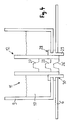
Figure 1 shows a steam iron comprising a water tank and a steam chamber. - Figure 2:
-
Figure 2 shows a water dosage device for controlling a flow of water from the water tank to the steam chamber. - Figure 3:
-
Figure 3 shows a perspective view of the tubular element. - Figure 4:
-
Figure 4 shows a water tank with a water dosage device fluidically connected with a steam chamber. - Figure 5:
-
Figure 5 shows a further example of a water dosage device that comprises an anti-drip valve. - Figure 6:
-
Figure 6 shows yet another example of a water dosage device. - In the following description of preferred embodiments of the present invention, identical reference numerals denote identical or comparable components.
-
Figure 1 shows a side view of a steam iron 1 configured for providing a steaming operation during ironing. The steam iron 1 comprises asoleplate 2, a housing 3 with ahandle 4 and apower cable 5 for supplying power to the steam iron 1. The steam iron 1 further comprises asteam chamber 6 for evaporating water and generating steam, thesteam chamber 6 being heated byheating elements 7. The steam generated in thesteam chamber 6 expels throughsteam outlet ports 8 disposed in thesoleplate 2. Awater tank 9 is located above thesteam chamber 6, with thewater tank 9 being adapted for supplyingwater 10 to thesteam chamber 6. Awater dosage device 11 is located at the fluidic connection between thewater tank 9 and thesteam chamber 6, whereby thewater dosage device 11 is configured for controlling the flow of water supplied to thesteam chamber 6. During normal steaming operation, thewater dosage device 11 is configured for supplying a moderate flow of water to thesteam chamber 6, with the flow rate corresponding approximately to the amount of water required for a steam generation. Thewater dosage device 11 is further configured for shutting off the flow path from thewater tank 9 to thesteam chamber 6, in order to deactivate the generation of steam. A further mode of operation is the cleaning mode. During regular steaming operation, especially in hard water areas, a layer of scale (generally calcium carbonate) is formed at the inner surfaces of thesteam chamber 6. For removing the layer of scale, the user may initiate a self-cleaning operation, whereby thewater dosage device 11 supplies a large amount of water to thesteam chamber 6. The cold water causes a thermal shock effect on the walls, resulting in the layer of scale being cracked and breaking into small particles, which, subsequently, can be rinsed away through thesteam outlet ports 8. - In
Figure 2 , thewater tank 9 is shown together with thewater dosage device 11. Thewater dosage device 11 comprises atubular element 12 that is inserted into acorresponding opening 13 of thebase plate 14 and extends through theopening 13. Thetubular element 12 is slidably supported by theopening 13 and can be moved relative to theopening 13 along the axial direction of thetubular element 12, as indicated byarrows tubular element 12 may be moved in a direction perpendicular to theopening 13 and to thebase plate 14, but thetubular element 12 may as well be moved in an oblique or slanted direction relative to theopening 13 and thebase plate 14. Thetubular element 12 is of cylindrical shape and comprises anouter wall 17 that encompasses ahollow interior 18. The inner contour of theopening 13 corresponds to the shape of thetubular element 12's outer surface. Preferably, to provide for a liquid-tight sealing between theopening 13 and thetubular element 12, a sealinggasket 19 is arranged between theopening 13 and thetubular element 12. As the area above thesteam chamber 6 may become quite hot, the sealinggasket 19 is preferably made of a temperature-resistant material like for example silicone rubber. -
Figure 3 shows a perspective view of thetubular element 12, whereby both theouter wall 17 and thehollow interior 18 are depicted. Preferably, thetubular element 12 is of cylindrical shape and has a circular cross-section with a diameter of more than 3 mm. For example, the outer surface of thetubular element 12 may have a diameter of 6 mm and theouter wall 17 may have a thickness of 1 mm. Preferably, thetubular element 12 is made of a plastic material, preferably of a high-performance thermoplastic resin like for example polyphenylene sulfide, also referred to as PPS, like for example Fortron, which is a registered trademark of Celanese. - At the bottom end 20 of the
tubular element 12, which is oriented towards thesteam chamber 6, thetubular element 12 is open. From therim 22 at the bottom end 20, a tapered cut-out 21 in theouter wall 17 extends in the direction towards the center of thetubular element 12. Preferably, the tapered cut-out 21 at the bottom end 20 extends approximately 4 to 10 mm in the direction towards the center of thetubular element 12. - As shown in
Figure 2 , thetubular element 12 may be moved to different positions relative to theopening 13, wherein in dependence on the respective position of thetubular element 12, different flow patterns and flow paths occur. InFigure 2 , different positions of thetubular element 12 are indicated by dashed lines, with the dashed lines indicating the position of the bottom end 20 of thetubular element 12. - For regular steaming operation, the
tubular element 12 may for example be moved to a position indicated with dashedline 23. In this position, the tapered cut-out 21 is partly located above the sealinggasket 19, so that the tapered cut-out 21 extends into thewater tank 9. Via the exposed part of the cut-out 21, water from thewater tank 9 can flow into thehollow interior 18 of thetubular element 12. InFigure 3 , the flow path via the cut-out 21 and thehollow interior 18 of thetubular element 12 is shown witharrows 24 and 25. At the bottom end 20 of thetubular element 12, a steady flow of water is dispensed to thesteam chamber 6 at a comparatively low flow rate. - The regular flow of water for the steaming operation can be adjusted by moving the
tubular element 12 relative to theopening 13. In case thetubular element 12 is moved in the upward direction, as indicated byarrow 15, the exposed part of the cut-out 21 is increased, and accordingly, the flow of water through the tapered cut-out 21 and thehollow interior 18 is increased as well. In case thetubular element 12 is moved in the downwards direction, as indicated byarrow 16, the exposed part of the cut-out 21 is reduced and correspondingly, the flow of water dispensed to thesteam chamber 6 is also reduced. Hence, by adjusting the position of thetubular element 12 relative to theopening 13, the flow of water dispensed to thesteam chamber 6 can be metered with high accuracy. - Furthermore, the flow of water can be shut off completely by moving the
tubular element 12 to a position indicated by dashedline 26. In this position, the cut-out 21 is entirely located below theopening 13 and does not extend into thewater tank 9 at all. As a consequence, the flow path from thewater tank 9 to thehollow interior 18 of thetubular element 12 is completely shut off, and no flow of water is supplied to thesteam chamber 6. - For removing the layers of scale that have been formed on the walls of the
steam chamber 6, it is necessary to supply a large flow of cold water to thesteam chamber 6. For performing the cleaning operation, thetubular element 12 may for example be moved to the position indicated by dashedline 27. In this position, thetubular element 12 is completely pulled out of theopening 13, with the bottom end 20 of thetubular element 12 being located above theopening 13. Accordingly, theopening 13 is completely exposed, andwater 10 from thewater tank 9 can flow through theopening 13 into thesteam chamber 6. As the diameter of theopening 13 is quite large and amounts to more than 3 mm, a sudden flush of cold water is supplied to thesteam chamber 6, in order to efficiently remove the layers of scale. - It has been described that the
tubular element 12 can be moved to a position for steam generation, to a position where the flow path is shut off or to a position for cleaning thesteam chamber 6. By moving thetubular element 12 to different positions relative to theopening 13, it is possible to switch between different flow paths. -
Figure 4 shows thewater tank 9, thewater dosage device 11 and the upper part of thesteam chamber 6 together with a modified sealinggasket 28 that provides a fluidic connection between thewater tank 9 and thesteam chamber 6. Firstly, the modified sealinggasket 28 provides for a liquid-tight sealing between theopening 13 and thetubular element 12. In addition to that, the sealinggasket 28 comprises aprotrusion 29 that extends in the downward direction. Theprotrusion 29 extends into anopening 30 in the upper part of thesteam chamber 6 and provides a fluidic connection between thewater tank 9 and thesteam chamber 6, with the upper part of thesteam chamber 6 abutting on the sealinggasket 28. During a steaming operation, the housing of thesteam chamber 6 may for example have a temperature of 170° C. The sealinggasket 28, which is preferably made of a temperature-resistant material, provides for a thermal decoupling between thewater tank 9 and thesteam chamber 6. -
Figure 5 shows another example of awater dosage device 31. Thewater dosage device 31 corresponds to thewater dosage device 11 shown inFigure 2 and comprises a sealinggasket 19 disposed between the opening 13 of thewater tank 9 and thetubular element 12, wherein the sealinggasket 19 provides a liquid-tight sealing between theopening 13 and thetubular element 12. Thewater dosage device 31 additionally comprises ananti-drip valve 32 with awater valve 33, adosing gasket 34 and abimetallic lever element 35. Theanti-drip valve 32 provides aflow path 36 for supplying water to thesteam chamber 6. As long as the temperature of thesteam chamber 6 has not reached a temperature of for example 150 to 170° C that is required for generating steam, thebimetallic lever element 35 does not push against thewater valve 33, thewater valve 33 remains in its closed position and theflow path 36 is shut off. Thus, it is prevented that water enters thesteam chamber 6 while the temperature of thesteam chamber 6 is still too low for generating steam. As soon as the temperature of thesteam chamber 6 has reached a temperature of for example 150 to 170° C, which is high enough for generating steam, thebimetallic lever element 35 pushes against thewater valve 33 in the direction indicated by arrow 37. Thewater valve 33 opens and accordingly, water from thewater tank 9 can flow via theflow path 36 to thetubular element 12. If theflow path 36 is open and thetubular element 12 is in a position indicated by dashedline 38, a flow of water can be supplied via the cut-out 21 and thehollow interior 18 of thetubular element 12 to thesteam chamber 6. In the example ofFigure 5 , thebase plate 39 of thedosing gasket 34 constitutes the base plate for thewater dosage device 31. Thebase plate 39 comprises anopening 40, with thetubular element 12 being movably encompassed by theopening 40. InFigure 5 , the sealinggasket 19 and thedosing gasket 34 are implemented as two separate parts. Alternatively, the sealinggasket 19 may be formed integrally with thedosing gasket 34. Thetubular element 12 can be positioned relative to thebase plate 39 of thedosing gasket 34. If thetubular element 12 is moved to the position indicated by dashedline 41, the supply of water to thesteam chamber 6 will be completely stopped. If thetubular element 12 is moved to the position indicated by dashedline 42, thetubular element 12 will be completely pulled out of theopening 13 and a large amount of water will be supplied to thesteam chamber 6, in order to provide for a cleaning and descaling operation. -
Figure 6 shows another example of awater dosage device 43. Thewater dosage device 43 is arranged in awater tank 9. As inFigure 5 , thewater dosage device 43 comprises ananti-drip valve 32 with awater valve 33, adosing gasket 34 and abimetallic lever element 35, with theanti-drip valve 32 providing aflow path 36 for supplying water via atubular element 44 to thesteam chamber 6. In the example ofFigure 6 , thetubular element 44 additionally comprises one or more transversal holes in theouter wall 45 of thetubular element 44. Furthermore, the sealinggasket 46 shown inFigure 6 protrudes in the upwards direction and comprises asleeve 47 that encompasses thetubular element 44. There exist a variety of different options for implementing thesleeve 47, the sealinggasket 46 and thedosing gasket 34. As shown inFigure 6 , thesleeve 47 may be formed integrally with the sealinggasket 46 and thedosing gasket 34 may be implemented as a separate part. Alternatively, thesleeve 47, the sealinggasket 46 and thedosing gasket 34 may be implemented as three separate parts. Further alternatively, thesleeve 47 may be implemented as a separate part and the sealinggasket 46 may be formed integrally with thedosing gasket 34. Further alternatively, thesleeve 47 may be formed integrally with the sealinggasket 46 and thedosing gasket 34, whereby thesleeve 47, the sealinggasket 46 and thedosing gasket 34 are implemented as one single piece. - In the position of the
tubular element 44 that is indicated by dashedline 48, the flow of water via ahollow interior 49 of thetubular element 44 is shut off. In this position of thetubular element 44, the location of the transversal holes is indicated withreference sign 50". It can be seen that the transversal holes atlocation 50" are covered by the sealinggasket 46 and thesleeve 47, so that there is no flow of water via the transversal holes atlocation 50". - In case the
tubular element 44 is moved to the position indicated by dashed line 51, there is a flow of water via theflow path 36 and thehollow interior 49 of thetubular element 44. The location of the transversal holes is now denoted with reference sign 50', and it can be seen that the transversal holes at location 50' are still covered by thesleeve 47, so that there is no additional flow of water via the transversal holes. - In case the
tubular element 44 is moved to the position indicated by dashedline 52, the cleaning flow path is opened. Thetubular element 44 is completely pulled out of thedosing gasket 34, and water may flow via theflow path 36 and theopening 40 of thedosing gasket 34. In the position of thetubular element 44 indicated by dashedline 52, the transversal holes are located at a location denoted withreference sign 50, and it can be seen fromFigure 6 that at thislocation 50, the transversal holes are no longer covered by thesleeve 47. Hence, in the cleaning position, there will be an additional flow of water via the transversal holes into thehollow interior 49 of thetubular element 44, which contributes to the overall flow during the cleaning operation. The advantage is that the up-down movement of thetubular element 44 is decreased. Thetubular element 44 only has to be lifted slightly above the opening in thedosing gasket 34, because the additional flow via the transversal holes atlocation 50 also contributes to the overall cleaning flow. Decreasing the up-down movement of thetubular element 44 may be advantageous when realising an actuation mechanism for controlling the movement of thetubular element 44. - The features described in the above description, claims and figures can be relevant to the invention in any combination. Their reference numerals in the claims have merely been introduced to facilitate reading of the claims. They are by no means meant to be limiting.
-
- 1
- steam iron
- 2
- soleplate
- 3
- housing
- 4
- handle
- 5
- power cable
- 6
- steam chamber
- 7
- heating element
- 8
- steam outlet ports
- 9
- water tank
- 10
- water
- 11
- water dosage device
- 12
- tubular element
- 13
- opening
- 14
- base plate
- 15
- arrow
- 16
- arrow
- 17
- outer wall
- 18
- hollow interior
- 19
- sealing gasket
- 20
- bottom end of the tubular element
- 21
- tapered cut-out
- 22
- rim
- 23
- dashed line indicating a dispensing position
- 24
- arrow
- 25
- arrow
- 26
- dashed line indicating a shut-off position
- 27
- dashed line indicating a cleaning position
- 28
- modified sealing gasket
- 29
- protrusion
- 30
- opening
- 31
- water dosage device
- 32
- anti-drip valve
- 33
- water valve
- 34
- dosing gasket
- 35
- bimetallic lever element
- 36
- flow path
- 37
- arrow
- 38
- dashed line indicating a dispensing position
- 39
- base plate
- 40
- opening
- 41
- dashed line indicating a shut-off position
- 42
- dashed line indicating a cleaning position
- 43
- water dosage device
- 44
- tubular element
- 45
- outer wall
- 46
- sealing gasket
- 47
- sleeve
- 48
- dashed line indicating a shut-off position
- 49
- hollow interior
- 50
- location of transversal holes at cleaning position
- 50'
- location of transversal holes at dispensing position
- 50"
- location of transversal holes at shut-off position
- 51
- dashed line indicating a dispensing position
- 52
- dashed line indicating a cleaning position
Claims (17)
- A water dosage device (11, 31, 43) for a water tank (9), the water dosage device (11, 31, 43) being configured for controlling a flow of water supplied by the water tank (9), the water dosage device (11, 31, 43) comprising a base plate (14, 39) with an opening (13, 40) therein,
characterised by
a tubular element (12, 44) with an outer wall (17, 45) and a hollow interior (18, 49), the outer wall (17, 45) comprising at least one cut-out (21),
wherein the opening (13, 40) is configured for movably accommodating the tubular element (12, 44), with the opening (13, 40) being configured for slidably encompassing an outer surface of the tubular element (12, 44),
wherein the tubular element (12, 44) is movable to a dispensing position relative to the opening (13, 40), wherein in the dispensing position, the at least one cut-out (21) is partly or completely exposed to the water tank (9), wherein a dispensing flow path is provided from the water tank (9) via the exposed part of the at least one cut-out (21) and the hollow interior (18, 49) of the tubular element (12, 44),
wherein the tubular element (12, 44) is movable to a cleaning position relative to the opening (13, 40), wherein in the cleaning position, the tubular element (12, 44) is in a pulled-out position relative to the opening (13, 40), wherein the opening (13, 40) is released and via the opening (13, 40), a cleaning flow path for supplying an augmented flow of water is provided. - The water dosage device according to claim 1, wherein the tubular element (12, 44) is movable to a shut-off position relative to the opening (13, 40), wherein in the shut-off position, none of the at least one cut-out (21) is exposed to the water tank (9) and no flow of water is supplied by the water tank (9).
- The water dosage device according to claim 1 or claim 2, wherein in the dispensing position of the tubular element (12, 44), the flow rate of the dispensing flow path is adjustable by moving the tubular element (12, 44) relative to the opening (13, 40) in a way that the part of the at least one cut-out (21) that is exposed to the water tank (9) is varied.
- The water dosage device according to any one of claims 1 to 3, wherein at least one (21) of the cut-outs is arranged at an end (20) of the tubular element (12, 44) facing away from the water tank (9).
- The water dosage device according to any one of claims 1 to 4, wherein at least one (21) of the cut-outs is tapered in an axial direction of the tubular element (12, 44).
- The water dosage device according to any one of claims 1 to 5, wherein the tubular element (12, 44) is open at an end (20) facing away from the water tank (9), in order to dispense a flow of water.
- The water dosage device according to any one of claims 1 to 6, wherein the water dosage device (11, 31, 43) is configured for supplying water to a steam chamber (6) located below the water tank (9).
- The water dosage device according to any one of claims 1 to 7, wherein in the cleaning position of the tubular element (12, 44), the augmented flow of water supplied to the steam chamber (6) via the cleaning flow path is adapted for descaling of the steam chamber (6).
- The water dosage device according to any one of claims 1 to 8, wherein a floor plate of the water tank (9) constitutes the base plate (14) of the water dosage device (11, 31,43).
- The water dosage device according to any one of claims 1 to 8, wherein the water dosage device (11, 31, 43) comprises an anti-drip valve (32) for controlling a flow path to the tubular element (12, 44), the anti-drip valve (32) being configured for shutting off the flow path as long as a target temperature of a steam chamber (6) for generating steam has not been reached yet.
- The water dosage device according to any one of claims 1 to 10, wherein in addition to the at least one cut-out (21), the tubular element (44) comprises at least one transversal hole, wherein the water dosage device (11, 31, 43) further comprises a sleeve (47) encompassing the tubular element (12, 44), wherein in the dispensing position of the tubular element (12, 44), the sleeve (47) is adapted for blocking a flow of water through the at least one transversal hole, and wherein in the cleaning position of the tubular element (12, 44) relative to the opening (13, 40), an additional flow of water via the least one transversal hole is supplied.
- A water dosage device for a water tank (9), the water dosage device (11, 31, 43) being configured for controlling a flow of water supplied by the water tank (9), the water dosage device (11, 31, 43) comprising a base plate (14, 39) with an opening (13, 40) therein,
characterised by
a tubular element (12, 44) with an outer wall (17, 45) and a hollow interior (18, 49), the outer wall (17, 45) comprising at least one cut-out (21),
wherein the opening (13, 40) is configured for movably accommodating the tubular element (12, 44), with the opening (13, 40) being configured for slidably encompassing an outer surface of the tubular element (12, 44),
wherein the tubular element (12, 44) is movable to a dispensing position relative to the opening (13, 40), wherein in the dispensing position, the at least one cut-out (21) is partly or completely exposed to the water tank (9), wherein a dispensing flow path is provided from the water tank (9) via the exposed part of the at least one cut-out (21) and the hollow interior (18, 49) of the tubular element (12, 44),
wherein the tubular element (12, 44) is movable to a shut-off position relative to the opening (13, 40), wherein in the shut-off position, none of the at least one cut-out (21) is exposed to the water tank (9) and no flow of water is supplied by the water tank (9). - The water dosage device according to claim 12, wherein the tubular element (12, 44) is movable to a cleaning position relative to the opening (13, 40), wherein in the cleaning position, the tubular element (12, 44) is in a pulled-out position relative to the opening (13, 40), wherein the opening (13, 40) is released and via the opening (13, 40), a cleaning flow path for supplying an augmented flow of water is provided.
- A steam iron (1) comprising
a water tank (9) with a water dosage device (11, 31, 43) according to one of claims 1 to 13,
a steam chamber (6) adapted for generating steam, with the water dosage device (11, 31, 43) being configured for supplying water to the steam chamber (6). - A method for controlling a flow of water supplied by a water tank (9) and a water dosage device (11, 31, 43), the water dosage device (11, 31, 43) comprising a base plate (14, 39) with an opening (13, 40) therein and a tubular element (12, 44) with an outer wall (17, 45) and a hollow interior (18, 49), the outer wall (17, 45) comprising at least one cut-out (21),
wherein the opening (13, 40) is configured for movably accommodating the tubular element (12, 44), with the opening (13, 40) being configured for slidably encompassing an outer surface of the tubular element (12, 44),
the method comprising a step of moving the tubular element (12, 44) to a dispensing position relative to the opening (13, 40), wherein in the dispensing position, the at least one cut-out (21) is partly or completely exposed to the water tank (9), wherein a dispensing flow path is provided from the water tank (9) via the exposed part of the at least one cut-out (21) and the hollow interior (18, 49) of the tubular element (12, 44). - The method according to claim 15, further comprising a step of adjusting the flow rate of the dispensing flow path in the dispensing position of the tubular element (12, 44) by moving the tubular element (12, 44) relative to the opening (13, 40) in a way that the part of the at least one cut-out (21) that is exposed to the water tank (9) is varied.
- A method for controlling a flow of water supplied by a water tank (9) and a water dosage device (11, 31, 43), the water dosage device (11, 31, 43) comprising a base plate (14, 39) with an opening (13, 40) therein and a tubular element (12, 44) with an outer wall (17, 45) and a hollow interior (18, 49), the outer wall (17, 45) comprising at least one cut-out (21),
wherein the opening (13, 40) is configured for movably accommodating the tubular element (12, 44), with the opening (13, 40) being configured for slidably encompassing an outer surface of the tubular element (12, 44),
the method comprising a step of moving the tubular element (12, 44) to a cleaning position relative to the opening (13, 40), wherein in the cleaning position, the tubular element (12, 44) is in a pulled-out position relative to the opening (13, 40), wherein the opening (13, 40) is released and via the opening (13, 40), a cleaning flow path for supplying an augmented flow of water is provided.
Applications Claiming Priority (1)
| Application Number | Priority Date | Filing Date | Title |
|---|---|---|---|
| ES201730590 | 2017-03-31 |
Publications (1)
| Publication Number | Publication Date |
|---|---|
| EP3392400A1 true EP3392400A1 (en) | 2018-10-24 |
Family
ID=61691350
Family Applications (1)
| Application Number | Title | Priority Date | Filing Date |
|---|---|---|---|
| EP18162286.1A Withdrawn EP3392400A1 (en) | 2017-03-31 | 2018-03-16 | Water dosage device for a steam iron |
Country Status (2)
| Country | Link |
|---|---|
| EP (1) | EP3392400A1 (en) |
| DE (1) | DE102017210053A1 (en) |
Cited By (1)
| Publication number | Priority date | Publication date | Assignee | Title |
|---|---|---|---|---|
| WO2021214350A1 (en) | 2020-04-23 | 2021-10-28 | Sda Factory Vitoria, S.L.U. | Water dosing system |
Citations (3)
| Publication number | Priority date | Publication date | Assignee | Title |
|---|---|---|---|---|
| US4837952A (en) * | 1986-10-31 | 1989-06-13 | Seb S.A. | Steam iron having variable heat conductivity between the heating base and sole plate |
| US5531037A (en) * | 1994-01-29 | 1996-07-02 | Braun Aktiengesellschaft | Water proportioning device for steam irons |
| EP1007777B1 (en) | 1998-03-04 | 2003-12-10 | Koninklijke Philips Electronics N.V. | Device for ironing laundry |
Family Cites Families (4)
| Publication number | Priority date | Publication date | Assignee | Title |
|---|---|---|---|---|
| DE1585764B2 (en) * | 1966-05-26 | 1976-07-22 | VEB Elektro-Haushaltgeräte Brandenburg, χ 1800 Brandenburg | ELECTRIC STEAM IRON |
| FR2449157A1 (en) * | 1979-02-13 | 1980-09-12 | Seb Sa | WATER INJECTION DEVICE FOR STEAM IRON, AND STEAM IRON |
| DD244778A1 (en) * | 1985-12-24 | 1987-04-15 | Soernewitz Elektrowaerme Veb | WATER VALVE FOR ELECTRIC BUCKETS WITH DRIP LOCK |
| US5829175A (en) * | 1996-09-20 | 1998-11-03 | Black & Decker Inc. | Steam iron with all temperature steam production |
-
2017
- 2017-06-14 DE DE102017210053.2A patent/DE102017210053A1/en not_active Withdrawn
-
2018
- 2018-03-16 EP EP18162286.1A patent/EP3392400A1/en not_active Withdrawn
Patent Citations (3)
| Publication number | Priority date | Publication date | Assignee | Title |
|---|---|---|---|---|
| US4837952A (en) * | 1986-10-31 | 1989-06-13 | Seb S.A. | Steam iron having variable heat conductivity between the heating base and sole plate |
| US5531037A (en) * | 1994-01-29 | 1996-07-02 | Braun Aktiengesellschaft | Water proportioning device for steam irons |
| EP1007777B1 (en) | 1998-03-04 | 2003-12-10 | Koninklijke Philips Electronics N.V. | Device for ironing laundry |
Cited By (1)
| Publication number | Priority date | Publication date | Assignee | Title |
|---|---|---|---|---|
| WO2021214350A1 (en) | 2020-04-23 | 2021-10-28 | Sda Factory Vitoria, S.L.U. | Water dosing system |
Also Published As
| Publication number | Publication date |
|---|---|
| DE102017210053A1 (en) | 2018-10-04 |
Similar Documents
| Publication | Publication Date | Title |
|---|---|---|
| KR101851441B1 (en) | Sanitary installation part and sanitary fitting having the same | |
| US4208746A (en) | Human body irrigation system | |
| US6105286A (en) | Device for ironing with bypass for selfcleaning | |
| RU2688905C2 (en) | Hot water supply unit for coffee machine "espresso" or similar and corresponding machine | |
| US5630287A (en) | Electric steam iron | |
| AU2003204244A1 (en) | Improvements in or relating to ablutionary water supply installations | |
| JP5330367B2 (en) | Mist generator | |
| RU2459022C2 (en) | Steam iron | |
| GB2341667A (en) | An instantaneous water heater with an on-off valve to control power and water supply | |
| JP2016200332A (en) | Hot water supply system and control method for the same | |
| KR100775599B1 (en) | Water heater with instant heating | |
| CN109972374B (en) | Ironing appliance equipped with a primary evaporation chamber and a secondary evaporation chamber | |
| KR20190100186A (en) | Control fittings to control differential pressure and / or volumetric flow | |
| WO2007118702A1 (en) | Thermostatic device for water and energy saving | |
| US6343389B1 (en) | Water outlets for an ablutionary device or appliance | |
| CN101501268A (en) | Steam iron | |
| ITMI20062401A1 (en) | SUPPLY VALVE OF A FLUID METHOD OF OPERATION OF THE VALVE MACHINE FOR THE PREPARATION OF HOT DRINKS INCLUDING SUCH VALVE AND METHOD OF DRIVING SUCH A MACHINE | |
| KR102306989B1 (en) | Auto shower apparatus | |
| JP2001165336A (en) | Hot water tapping prevention valve | |
| KR102953476B1 (en) | Ball top double safety device for cold and hot water | |
| JP2021122488A (en) | Cold water discharge device | |
| KR100821369B1 (en) | Hot and cold water heater with safety shut-off system | |
| JP4931259B2 (en) | Human body cleaning device | |
| JP2010240150A (en) | Heating device for steam apparatus | |
| JP7176963B2 (en) | Outlet cap and drinking water supply device |
Legal Events
| Date | Code | Title | Description |
|---|---|---|---|
| PUAI | Public reference made under article 153(3) epc to a published international application that has entered the european phase |
Free format text: ORIGINAL CODE: 0009012 |
|
| AK | Designated contracting states |
Kind code of ref document: A1 Designated state(s): AL AT BE BG CH CY CZ DE DK EE ES FI FR GB GR HR HU IE IS IT LI LT LU LV MC MK MT NL NO PL PT RO RS SE SI SK SM TR |
|
| AX | Request for extension of the european patent |
Extension state: BA ME |
|
| 17P | Request for examination filed |
Effective date: 20190424 |
|
| RBV | Designated contracting states (corrected) |
Designated state(s): AL AT BE BG CH CY CZ DE DK EE ES FI FR GB GR HR HU IE IS IT LI LT LU LV MC MK MT NL NO PL PT RO RS SE SI SK SM TR |
|
| STAA | Information on the status of an ep patent application or granted ep patent |
Free format text: STATUS: THE APPLICATION IS DEEMED TO BE WITHDRAWN |
|
| 18D | Application deemed to be withdrawn |
Effective date: 20190425 |