EP3392361A1 - Thick steel plate having excellent cryogenic toughness - Google Patents
Thick steel plate having excellent cryogenic toughness Download PDFInfo
- Publication number
- EP3392361A1 EP3392361A1 EP16875576.7A EP16875576A EP3392361A1 EP 3392361 A1 EP3392361 A1 EP 3392361A1 EP 16875576 A EP16875576 A EP 16875576A EP 3392361 A1 EP3392361 A1 EP 3392361A1
- Authority
- EP
- European Patent Office
- Prior art keywords
- less
- content
- steel plate
- thick steel
- temperature
- Prior art date
- Legal status (The legal status is an assumption and is not a legal conclusion. Google has not performed a legal analysis and makes no representation as to the accuracy of the status listed.)
- Withdrawn
Links
Images
Classifications
-
- C—CHEMISTRY; METALLURGY
- C22—METALLURGY; FERROUS OR NON-FERROUS ALLOYS; TREATMENT OF ALLOYS OR NON-FERROUS METALS
- C22C—ALLOYS
- C22C38/00—Ferrous alloys, e.g. steel alloys
- C22C38/18—Ferrous alloys, e.g. steel alloys containing chromium
- C22C38/40—Ferrous alloys, e.g. steel alloys containing chromium with nickel
- C22C38/50—Ferrous alloys, e.g. steel alloys containing chromium with nickel with titanium or zirconium
-
- C—CHEMISTRY; METALLURGY
- C21—METALLURGY OF IRON
- C21D—MODIFYING THE PHYSICAL STRUCTURE OF FERROUS METALS; GENERAL DEVICES FOR HEAT TREATMENT OF FERROUS OR NON-FERROUS METALS OR ALLOYS; MAKING METAL MALLEABLE, e.g. BY DECARBURISATION OR TEMPERING
- C21D8/00—Modifying the physical properties of ferrous metals or ferrous alloys by deformation combined with, or followed by, heat treatment
- C21D8/02—Modifying the physical properties of ferrous metals or ferrous alloys by deformation combined with, or followed by, heat treatment during manufacturing of plates or strips
-
- C—CHEMISTRY; METALLURGY
- C22—METALLURGY; FERROUS OR NON-FERROUS ALLOYS; TREATMENT OF ALLOYS OR NON-FERROUS METALS
- C22C—ALLOYS
- C22C38/00—Ferrous alloys, e.g. steel alloys
- C22C38/001—Ferrous alloys, e.g. steel alloys containing N
-
- C—CHEMISTRY; METALLURGY
- C22—METALLURGY; FERROUS OR NON-FERROUS ALLOYS; TREATMENT OF ALLOYS OR NON-FERROUS METALS
- C22C—ALLOYS
- C22C38/00—Ferrous alloys, e.g. steel alloys
- C22C38/02—Ferrous alloys, e.g. steel alloys containing silicon
-
- C—CHEMISTRY; METALLURGY
- C22—METALLURGY; FERROUS OR NON-FERROUS ALLOYS; TREATMENT OF ALLOYS OR NON-FERROUS METALS
- C22C—ALLOYS
- C22C38/00—Ferrous alloys, e.g. steel alloys
- C22C38/04—Ferrous alloys, e.g. steel alloys containing manganese
-
- C—CHEMISTRY; METALLURGY
- C22—METALLURGY; FERROUS OR NON-FERROUS ALLOYS; TREATMENT OF ALLOYS OR NON-FERROUS METALS
- C22C—ALLOYS
- C22C38/00—Ferrous alloys, e.g. steel alloys
- C22C38/06—Ferrous alloys, e.g. steel alloys containing aluminium
-
- C—CHEMISTRY; METALLURGY
- C22—METALLURGY; FERROUS OR NON-FERROUS ALLOYS; TREATMENT OF ALLOYS OR NON-FERROUS METALS
- C22C—ALLOYS
- C22C38/00—Ferrous alloys, e.g. steel alloys
- C22C38/18—Ferrous alloys, e.g. steel alloys containing chromium
- C22C38/40—Ferrous alloys, e.g. steel alloys containing chromium with nickel
- C22C38/42—Ferrous alloys, e.g. steel alloys containing chromium with nickel with copper
-
- C—CHEMISTRY; METALLURGY
- C22—METALLURGY; FERROUS OR NON-FERROUS ALLOYS; TREATMENT OF ALLOYS OR NON-FERROUS METALS
- C22C—ALLOYS
- C22C38/00—Ferrous alloys, e.g. steel alloys
- C22C38/18—Ferrous alloys, e.g. steel alloys containing chromium
- C22C38/40—Ferrous alloys, e.g. steel alloys containing chromium with nickel
- C22C38/44—Ferrous alloys, e.g. steel alloys containing chromium with nickel with molybdenum or tungsten
-
- C—CHEMISTRY; METALLURGY
- C22—METALLURGY; FERROUS OR NON-FERROUS ALLOYS; TREATMENT OF ALLOYS OR NON-FERROUS METALS
- C22C—ALLOYS
- C22C38/00—Ferrous alloys, e.g. steel alloys
- C22C38/18—Ferrous alloys, e.g. steel alloys containing chromium
- C22C38/40—Ferrous alloys, e.g. steel alloys containing chromium with nickel
- C22C38/46—Ferrous alloys, e.g. steel alloys containing chromium with nickel with vanadium
-
- C—CHEMISTRY; METALLURGY
- C22—METALLURGY; FERROUS OR NON-FERROUS ALLOYS; TREATMENT OF ALLOYS OR NON-FERROUS METALS
- C22C—ALLOYS
- C22C38/00—Ferrous alloys, e.g. steel alloys
- C22C38/18—Ferrous alloys, e.g. steel alloys containing chromium
- C22C38/40—Ferrous alloys, e.g. steel alloys containing chromium with nickel
- C22C38/48—Ferrous alloys, e.g. steel alloys containing chromium with nickel with niobium or tantalum
-
- C—CHEMISTRY; METALLURGY
- C21—METALLURGY OF IRON
- C21D—MODIFYING THE PHYSICAL STRUCTURE OF FERROUS METALS; GENERAL DEVICES FOR HEAT TREATMENT OF FERROUS OR NON-FERROUS METALS OR ALLOYS; MAKING METAL MALLEABLE, e.g. BY DECARBURISATION OR TEMPERING
- C21D2211/00—Microstructure comprising significant phases
- C21D2211/001—Austenite
-
- C—CHEMISTRY; METALLURGY
- C21—METALLURGY OF IRON
- C21D—MODIFYING THE PHYSICAL STRUCTURE OF FERROUS METALS; GENERAL DEVICES FOR HEAT TREATMENT OF FERROUS OR NON-FERROUS METALS OR ALLOYS; MAKING METAL MALLEABLE, e.g. BY DECARBURISATION OR TEMPERING
- C21D6/00—Heat treatment of ferrous alloys
- C21D6/004—Heat treatment of ferrous alloys containing Cr and Ni
-
- C—CHEMISTRY; METALLURGY
- C21—METALLURGY OF IRON
- C21D—MODIFYING THE PHYSICAL STRUCTURE OF FERROUS METALS; GENERAL DEVICES FOR HEAT TREATMENT OF FERROUS OR NON-FERROUS METALS OR ALLOYS; MAKING METAL MALLEABLE, e.g. BY DECARBURISATION OR TEMPERING
- C21D8/00—Modifying the physical properties of ferrous metals or ferrous alloys by deformation combined with, or followed by, heat treatment
- C21D8/02—Modifying the physical properties of ferrous metals or ferrous alloys by deformation combined with, or followed by, heat treatment during manufacturing of plates or strips
- C21D8/0221—Modifying the physical properties of ferrous metals or ferrous alloys by deformation combined with, or followed by, heat treatment during manufacturing of plates or strips characterised by the working steps
- C21D8/0226—Hot rolling
-
- C—CHEMISTRY; METALLURGY
- C21—METALLURGY OF IRON
- C21D—MODIFYING THE PHYSICAL STRUCTURE OF FERROUS METALS; GENERAL DEVICES FOR HEAT TREATMENT OF FERROUS OR NON-FERROUS METALS OR ALLOYS; MAKING METAL MALLEABLE, e.g. BY DECARBURISATION OR TEMPERING
- C21D8/00—Modifying the physical properties of ferrous metals or ferrous alloys by deformation combined with, or followed by, heat treatment
- C21D8/02—Modifying the physical properties of ferrous metals or ferrous alloys by deformation combined with, or followed by, heat treatment during manufacturing of plates or strips
- C21D8/0247—Modifying the physical properties of ferrous metals or ferrous alloys by deformation combined with, or followed by, heat treatment during manufacturing of plates or strips characterised by the heat treatment
- C21D8/0263—Modifying the physical properties of ferrous metals or ferrous alloys by deformation combined with, or followed by, heat treatment during manufacturing of plates or strips characterised by the heat treatment following hot rolling
-
- C—CHEMISTRY; METALLURGY
- C21—METALLURGY OF IRON
- C21D—MODIFYING THE PHYSICAL STRUCTURE OF FERROUS METALS; GENERAL DEVICES FOR HEAT TREATMENT OF FERROUS OR NON-FERROUS METALS OR ALLOYS; MAKING METAL MALLEABLE, e.g. BY DECARBURISATION OR TEMPERING
- C21D9/00—Heat treatment, e.g. annealing, hardening, quenching or tempering, adapted for particular articles; Furnaces therefor
- C21D9/46—Heat treatment, e.g. annealing, hardening, quenching or tempering, adapted for particular articles; Furnaces therefor for sheet metals
Definitions
- the present disclosure relates to a thick steel plate, and more particularly to a thick steel plate having satisfactory toughness at a cryogenic temperature of -196°C [particularly, toughness in the plate width direction (C-direction)] even when a Ni content is 5.50 to 7.5%.
- a cryogenic temperature of -196°C
- LNG liquefied natural gas
- the thick steel plate of the present disclosure is not limited to these thick steel plates and is applicable to all thick steel plates for use in applications where the thick steel plates are exposed to the cryogenic temperature of -196°C.
- Thick steel plates for LNG tank used in a storage tank of a liquefied natural gas (LNG) are required to have not only high strengths but also such high toughness as to endure a cryogenic temperature of -196°C.
- LNG liquefied natural gas
- Non-Patent Document 1 mentions, for example, an influence of ⁇ (ferrite)- ⁇ (austenite) two-phase coexisting region (between A c1 point and A c3 point) heat treatment (sometimes referred to as an L treatment) on the low-temperature toughness of a 6% Ni steel.
- test piece mentioned in Non-Patent Document 1 mentioned above is excellent in cryogenic toughness in the L-direction (rolling direction) but tends to be inferior in cryogenic toughness in the C-direction (plate width direction) as compared with that in the L-direction.
- Patent Document 1 mentions a method in which a treatment of hot-rolling a steel containing 4.0 to 10% of Ni and having an austenite grain size controlled in a predetermined range and heating to a temperature range between A c1 point and A c3 point (corresponding to the L treatment of Non-Patent Document 1 mentioned above), followed by cooling is repeated one or more times and then tempering is performed at the temperature of A c1 point or lower.
- Patent Document 2 mentions that a steel containing 4.0% to 10% of Ni and having an AlN size controlled to 1 ⁇ m or less before hot rolling is subjected to the same heat treatment (L treatment and subsequent tempering treatment) as in Patent Document 1 mentioned above. These documents mention an impact value (vE -196 ) at -196°C. It is estimated that this impact value is an impact value in the L-direction, and the impact value in the C-direction is unclear.
- Non-Patent Document 2 mentions the development of a 6% Ni steel for LNG tank in which the L treatment (two-phase coexisting region heat treatment) mentioned above is used in combination with a thermo-mechanical control process (TMCP).
- Non-Patent Document 2 mentions that the toughness in the L-direction (rolling direction) exhibits a high value.
- Patent Document 3 mentions a Ni-reduced type thick steel plate for low temperature use, which is excellent in breakage resistant safety like 9% Ni steel even under low-temperature environment at -165°C or lower.
- This thick steel plate for low temperature use contains more than 5.0% and less than 8.0% of Ni and exhibits a yield strength of 590 MPa or more at normal temperature.
- Patent Document 3 mentions an improvement in toughness of a thick steel sheet by reducing a thickness of the steel ingot at the end of rough rolling to 3 to 8 times a thickness of the product in rough rolling to be applied to the heated steel ingot.
- Patent Document 3 mention that a tensile test at -165°C is performed using a test piece taken from the direction perpendicular to the rolling direction to measure the tensile strength TS and the yield strength YS and to measure the Charpy absorption energy vE -196 per unit area of fracture surface. This Charpy absorption energy vE -196 is determined as an average of three test pieces.
- Non-Patent Document 3 mentions that, when a steel containing about 5 to 11% of Ni is subjected to a two-phase region heat treatment to form a structure in which a small amount of stable residual austenite is dispersed in tempered martensite, the transition temperature significantly decreases and the steel exhibits excellent toughness even at low temperature. The document mentions that this is because the formation of austenite along the lath boundary causes division of block and packet that become cleavage fracture surface unit, leading to refining.
- the brittle fracture surface rate indicates an area ratio of the brittle fracture surface generated when a load is applied in a Charpy impact test. At the site where brittle fracture occurred, energy absorbed by a steel material until the fracture significantly decreases and the fracture easily proceeds. Therefore, in the technique for improving the cryogenic toughness, it is also an extremely important requirement to set the brittle fracture rate at -196°C at 10% or less.
- the present applicant has proposed a high-strength thick steel plate having excellent cryogenic toughness at - 196°C (particularly, cryogenic toughness in the C-direction) and a brittle fracture rate suppressed to 10% or less in a Ni steel having a Ni content of about 5.0 to 7.5% in Patent Document 4.
- This thick steel plate is characterized in that the content of Mn-based inclusions having a maximum diameter of more than 0.1 ⁇ m existing in the steel is in a range of 0.001 to 0.07% by mass and a fraction of the residual austenite phase existing at -196°C is in a range of 2.0 to 12.0% by volume.
- Patent Document 4 proposed previously by the present applicant, the cryogenic toughness at -196°C (particularly, cryogenic toughness in the C-direction) was evaluated by the brittle fracture rate at -196°C.
- the inventors have intensively studied and found it necessary to suppress the brittle fracture rate at -196°C to 10% or less and to obtain stable toughness when a general-purpose Charpy impact test is performed at -196°C, in order to further improve the cryogenic toughness at -196°C. Namely, it has been found that, when a Charpy impact test is performed at -196°C using plural test pieces, not the average but the minimum value of absorption energy may be set at 150 J or more.
- the present disclosure has been made in the light of the above circumstances and an object thereof is to provide a thick steel plate having excellent cryogenic toughness particularly in the C-direction that the minimum value of absorption energy satisfies 150 J or more, on the assumption that a tensile strength is 690 to 830 MPa, a yield strength is 590 MPa or more, and a brittle fracture rate is 10% or less when a Charpy impact test is performed at -196°C in a Ni steel having a Ni. content of 5.50 to 7.5%.
- a thick steel plate having excellent cryogenic toughness of the present disclosure includes, in % by mass: 0.04 to 0.09% of C, more than 0% and 0.30% or less of Si, 0.50 to 1.10% of Mn, more than 0% and 0.004% or less of P, more than 0% and less than 0.0030% of S, 0.010 to 0.040% of Al, 5.50 to 7.5% of Ni, 0.30 to 0.6% of Cr, more than 0% and 0.20% or less of Mo, and more than 0% and 0.0055% or less of N, with the balance being iron and inevitable impurities, wherein a volume fraction v of the residual austenite phase existing at -196°C is 4.0 to 12%, and a fracture unit configuration parameter M value represented by the following formula (1) satisfies 2.4 or more when t is a thickness of the thick steel plate.
- DI is a value calculated by the following formula (2) and [] represents the content (% by mass) of each element.
- the thick steel plate may further include, in % by mass:
- a fracture unit configuration parameter M value calculated based on DI calculated from the composition of a thick steel plate, the volume fraction v, and a thickness t of the thick steel plate is appropriately adjusted. Therefore, while satisfying the tensile strength of 690 to 830 MPa, the yield strength of 590 MPa or more, and the brittle fracture rate of 10% or less when a Charpy impact test is performed at -196°C, it is possible to set the minimum value of absorption energy at 150 J or more.
- This thick steel plate is excellent in cryogenic toughness particularly in the C-direction.
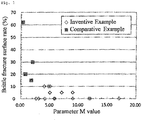
- Fig. 1 is a graph showing a relationship between a fracture unit configuration parameter M value and a brittle fracture rate.
- the inventors have intensively studied so as to further improve the cryogenic toughness at -196°C in the C-direction while ensuring high strength even after proposal of the technique of Patent Document 4.
- it is important to set a volume fraction v of a residual austenite phase existing at - 196°C at 4.0 to 12%, and a fracture unit configuration parameter M value calculated based on DI calculated from the composition of a thick steel plate, the volume fraction v, and a thickness t of the thick steel plate may be controlled to 2.4 or more, thus completing a thick steel plate of the present disclosure.
- appropriate control of the fracture unit configuration parameter M value enables suppression of coarsening of a fracture unit that causes degradation of the toughness, thus realizing extremely excellent cryogenic toughness.
- excellent cryogenic toughness means that, when a Charpy impact test in the C-direction (plate width direction) is performed at -196°C by the method mentioned in the below-mentioned Examples, a brittle fracture rate of 10% or less and the minimum value of absorption energy of 150 J or more are satisfied. In the below-mentioned Examples, a Charpy impact test in the L-direction (rolling direction) is not performed. However, according to empirical rules, it is considered that the toughness in the L-direction necessarily becomes satisfactory if the toughness in the C-direction is satisfactory.
- thick steel plate means a steel plate having a thickness of about 6 to 50 mm.
- a thick steel plate according to the embodiment of the present invention will be described below.
- the thick steel plate of the embodiment of the present invention includes, in % by mass: 0.04 to 0.09% of C, more than 0% and 0.30% or less of Si, 0.50 to 1.10% of Mn, more than 0% and 0.004% or less of P, more than 0% and less than 0.0030% of S, 0.010 to 0.040% of Al, 5.50 to 7.5% of Ni, 0.30 to 0.6% of Cr, more than 0% and 0.20% or less of Mo, and more than 0% and 0.0055% or less of N, as basic components.
- % means % by mass.
- Carbon (C) is an element required to increase the strength and to ensure the amount of residual ⁇ at -196°C.
- the C content of less than 0.04% leads to strength poverty. It is not able to ensure the amount of residual ⁇ at -196°C, thus failing to improve the cryogenic toughness. Therefore, in the embodiment of the present invention, the C content is set at 0.04% or more.
- the C content is preferably 0.045% or more, and more preferably 0.05% or more.
- the C content of more than 0.09% leads to excessively high strength, thus degrading the cryogenic toughness. Therefore, in the embodiment of the present invention, the C content is set at 0.09% or less.
- the C content is preferably 0.08% or less, and more preferably 0.07% or less.
- Silicon (Si) is an element serving as a deoxidizing agent.
- the Si content is preferably 0.01% or more.
- the Si content is more preferably 0.03% or more, and still more preferably 0.05% or more.
- the Si content is set at 0.30% or less.
- the Si content is preferably 0.25% or less, and more preferably 0.20% or less.
- Manganese (Mn) is an element that stabilizes ⁇ , which is required to ensure the amount of residual austenite at - 196°C. From such a point of view, the Mn content is set at 0.50% or more in the embodiment of the present invention.
- the Mn content is preferably 0.60% or more, and more preferably 0.70% or more.
- excessive Mn content causes tempering embrittlement, thus failing to improve the cryogenic toughness. Therefore, in the embodiment of the present invention, the Mn content is set at 1.10% or less.
- the Mn content is preferably 1.05% or less, and more preferably 1.00% or less.
- Phosphor (P) is an impurity element that causes grain boundary embrittlement, thus failing to improve the cryogenic toughness. Therefore, in the embodiment of the present invention, the P content is set at 0.004% or less.
- the P content is preferably 0.003% or less, and more preferably 0.002% or less.
- the P content is preferably decreased as much as possible. However, it is industrially difficult to set the P content at 0%.
- the S content is set at less than 0.0030%.
- the S content is preferably 0.0025% or less, and more preferably 0.0020% or less.
- the S content is preferably decreased as much as possible. However, it is industrially difficult to set the S content at 0%.
- Aluminum (Al) is an element that serves as a deoxidizing agent. Too small Al content leads to an increase in oxygen concentration in the steel and an increase in amount of coarse Al-based inclusions, thus failing to improve the cryogenic toughness. Therefore, in the embodiment of the present invention, the Al content is set at 0.010% or more. The Al content is preferably 0.015% or more, and more preferably 0.020% or more. Like Si, excessive Al content accelerates the formation of hard island-shaped martensite phase, thus failing to improve the cryogenic toughness. Therefore, in the embodiment of the present invention, the Al content is set at 0.040% or less. The Al content is preferably 0.035% or less, and more preferably 0.030% or less.
- Nickel (Ni) is an element required to ensure the amount of residual austenite at -196°C and to improve the cryogenic toughness. Therefore, in the embodiment of the present invention, the Ni content is set at 5.50% or more.
- the Ni content is preferably 6.00% or more, and more preferably 6.50% or more.
- the Ni content is preferably increased as much as possible. However, excessive Ni content leads to high cost. Therefore, in the embodiment of the present invention, the Ni content is set at 7.5% or less.
- the Ni content is preferably 7.4% or less, and more preferably 7.3% or less.
- Chromium is an element required to enhance the hardenability and to ensure the strength. To exert these effects, the Cr content is set at 0.30% or more in the embodiment of the present invention.
- the Cr content is preferably 0.35% or more, and more preferably 0.40% or more.
- the Cr content is set at 0.6% or less.
- the Cr content is preferably 0.55% or less, and more preferably 0.50% or less.
- Molybdenum (Mo) is an element that increases the strength and improves the cryogenic toughness. To effectively exert these actions, the Mo content is preferably 0.01% or more. The Mo content is more preferably 0.02% or more, and still more preferably 0.03% or more. However, excessive Mo content leads to excessively high strength, thus degrading the cryogenic toughness. Therefore, in the embodiment of the present invention, the Mo content is set at 0.20% or less. The Mo content is preferably 0.18% or less, and more preferably 0.16% or less.
- N Nitrogen
- the N content is set at 0.0055% or less.
- the N content is preferably 0.0050% or less, and more preferably 0.0045% or less.
- the N content is preferably decreased as much as possible. However, it is industrially difficult to set the N content at 0%.
- the thick steel plate of the embodiment of the present invention includes the above-mentioned components as basic components, the balance being iron and inevitable impurities.
- the inevitable impurities mean components that are mixed due to various factors of the manufacturing process, including raw materials such as ores and scraps, when a thick steel plate is industrially produced, the components being permittable as long as an adverse influence is not exerted on the present disclosure.
- the Nb content is preferably 0.001% or more, more preferably 0.003% or more, and still more preferably 0.005% or more.
- the Ti content is preferably 0.0001% or more, more preferably 0.0005% or more, and still more preferably 0.0010% or more.
- the V content is preferably 0.0001% or more, more preferably 0.0005% or more, and still more preferably 0.0010% or more.
- the Nb content is preferably 0.025% or less, more preferably 0.02% or less, and still more preferably 0.01% or less.
- the Ti content is preferably 0.02% or less, more preferably 0.01% or less, and still more preferably 0.005% or less.
- the V content is preferably 0.025% or less, more preferably 0.02% or less, and still more preferably 0.01% or less.
- composition of the thick steel plate according to the embodiment of the present invention has been described above.
- a volume fraction v of the residual ⁇ phase existing at -196°C satisfies a range of 4.0 to 12%.
- the residual ⁇ existing at -196°C contributes to an improvement in cryogenic toughness.
- the volume fraction of the residual ⁇ phase at-196°C in the entire metal structure is set at 4.0% or more.
- the volume fraction is preferably 6.0% or more, and more preferably 7.0% or more.
- the volume fraction of the residual ⁇ phase at -196°C in the entire metal structure is set at 12% or less.
- the volume fraction is preferably 10.0% or less, and more preferably 9.0% or less.
- a volume fraction v of the residual ⁇ phase existing at -196°C is important.
- the structure other than the residual ⁇ is not particularly limited as long as the structure usually exists in the thick steel plate.
- Examples of the structure other than the residual ⁇ include martensite, bainite, carbides such as cementite, and the like.
- a volume fraction v of the residual ⁇ phase at -196°C in the entire metal structure satisfies the above range, and a fracture unit configuration parameter M value calculated by the following formula (1) based on DI calculated from the composition of a thick steel plate, the volume fraction v, and a thickness t (mm) of the thick steel plate satisfies 2.4 or more.
- M value DI ⁇ v 2 / t
- DI is a value calculated by the following formula (2) and [] represents the content (% by mass) of each element.
- DI 1.16 ⁇ C / 10 0.5 ⁇ 0.7 ⁇ Si + 1 ⁇ 1 + 3.33 ⁇ Mn ⁇ 1 + 0.35 ⁇ Cu ⁇ 1 + 0.36 ⁇ Ni ⁇ 1 + 2.16 ⁇ Cr ⁇ 1 + 3 Mo ⁇ 1 + 1.75 ⁇ V ⁇ 1
- Non-Patent Document 3 cited as the prior art mentions that block and packet that become the fracture unit are divided by austenite formed along the lath boundary, leading to refining.
- the block diameter also has a relationship with DI, and the block diameter decreases as DI increases.
- the block diameter can be controlled by adjusting DI calculated based on the composition of the steel based on a relationship between the volume fraction of the residual austenite phase at -196°C and the plate thickness.
- the M value is preferably 2.6 or more, more preferably 2.8 or more, and still more preferably 3.0 or more.
- the M value is determined based on the composition of a steel , a volume fraction v of the residual ⁇ phase at -196°C, and a plate thickness t of the thick steel plate.
- the upper limit of the M value is about 24.
- the M value is more preferably 17 or less, and still more preferably 15 or less.
- the thick steel plate of the embodiment of the present invention is manufactured by heating a billet obtained by melting in accordance with a conventional method to the temperature in a range of 1,000 to 1,150°C, and then hot-rolling the billet in a non-recrystallization temperature region of austenite, and controlling a cumulative rolling reduction ratio in a temperature region of 830°C or lower to 25% or more and controlling a finish rolling temperature to 680°C or higher.
- the steel plate thus obtained is acceleratively cooled to a temperature region of 200°C or lower at an average cooling rate of 4°C/second or more.
- the steel plate is subjected to a tempering treatment by heating to the temperature in a two-phase region, holding, and then acceleratively cooled to a temperature region of 200°C or lower at an average cooling rate of 4°C/second or more.
- the billet obtained by melting is heated to the temperature in a range of 1,000 to 1,150°C.
- the billet before hot-rolling contains fine austenite grains. Refining of austenite grains of the billet before hot-rolling ensures the amount of residual ⁇ existing at -196°C. Therefore, in the embodiment of the present invention, the heating temperature before hot-rolling of the billet is set at 1,000°C or higher.
- the heating temperature is preferably 1,010°C or higher, and more preferably 1,020°C or higher.
- excessively high heating temperature might lead to coarsening of ⁇ , thus degrading the cryogenic toughness. Therefore, in the embodiment of the present invention, the heating temperature is set at 1,150°C or lower.
- the heating temperature is preferably 1,140°C or lower, and more preferably 1,130°C or lower.
- the billet was heated to the above temperature range, and then hot-rolled in a non-recrystallization temperature region of austenite, thereby adjusting a cumulative rolling reduction ratio in a temperature region of 830°C or lower to 25% or more and adjusting a finish rolling temperature to 680°C or higher. It is possible to refine the structure by performing hot-rolling in a non-recrystallization temperature region of austenite thereby adjusting a cumulative rolling reduction ratio in a temperature region of 830°C or lower to preferably 25% or more.
- the cumulative rolling reduction ratio is preferably 30% or more, and more preferably 35% or more.
- the finish rolling temperature is set at 680°C or higher, preferably 685°C or higher, and more preferably 690°C or higher.
- the upper limit of the finish rolling temperature is preferably set, for example, at 800°C.
- the thick steel plate After hot-rolling, the thick steel plate is cooled to a temperature region of 200°C or lower.
- An average cooling rate during cooling is set at 4°C/second or more. By setting the average cooling rate to 4°C/second or more, martensite can be formed.
- the average cooling rate is preferably 5°C/second or more, and more preferably 6°C/second or more.
- the upper limit of the average cooling rate is not particularly limited and is preferably set, for example, at 50°C/second.
- the finish cooling temperature after completion of the hot-rolling is 200°C or lower. If the finish cooling temperature after completion of the hot-rolling is higher than 200°C, martensite might be less likely formed, thus reducing the strength.
- the finish cooling temperature after completion of the hot-rolling is preferably 150°C or lower, and more preferably 100°C or lower.
- the hot-rolled steel plate After hot-roiling and further cooling to a temperature region of 200°C or lower, the hot-rolled steel plate is heated to the temperature TL (°C) in a two-phase region and then held.
- the amount of residual ⁇ existing at-196°C can be controlled in a predetermined range.
- the temperature TL in a two-phase region is the temperature in a range of A c1 point or higher and A c3 point or lower.
- the heating temperature is more preferably A c1 point + 60°C or higher, and more preferably A c3 point - 10°C or lower. Since the temperature of A c1 point of the thick steel plate with the composition define in the present disclosure is about 600°C and the temperature of A c3 point is about 750°C, the heating temperature TL in a two-phase region may be controlled in a range of 600 to 750°C.
- the heating temperature TL in a two-phase region is more preferably 660°C or higher, and still more preferably 740°C or lower.
- a c1 point and A c3 point are calculated based on the following formulas (" Course: Metallurgy in Modern Times, Book of Materials, Vol. 4, Iron and Steel Material)" edited by The Japan Institute of Metals ).
- a c1 point 723 ⁇ 10.7 ⁇ Mn ⁇ 16.9 ⁇ Ni + 29.1 ⁇ Si + 16.9 ⁇ Cr + 290 ⁇ As + 6.38 ⁇ W
- a c 3 point 910 ⁇ 203 ⁇ C 0.5 ⁇ 15.2 ⁇ Ni + 44.7 ⁇ Si + 104 ⁇ V + 31.5 ⁇ Mo + 13.1 ⁇ W
- [] represents the content (% by mass) of an alloy element in the steel.
- As and W are not included as the components in the steel, so that each content of [As] and [W] is 0% in the above formula.
- the retention time tL (minute) in a two-phase region is set in a range of 15 to 40 minutes. If the retention time tL is less than 15 minutes, the concentration of the alloy element to the ⁇ phase does not sufficiently proceed, thus decreasing the strength.
- the retention time tL is preferably 20 minutes or more, and more preferably 25 minutes or more. However, if the retention time tL is more than 40 minutes, a ⁇ phase is annealed, thus reducing the strength.
- the retention time tL is preferably 35 minutes or less, and more preferably 30 minutes or less.
- the steel plate After heating in a two-phase region and holding, the steel plate is cooled to 200°C or lower.
- the average cooling rate during cooling is set at 4°C/second or more to quench. If the average cooling rate is less than 4°C/second, austenite might not partially undergo martensite transformation, thus causing reduction in strength and/or insufficient amount of residual ⁇ .
- the average cooling rate is preferably 5°C/second or more, and more preferably 6°C/second or more.
- the steel plate After heating in two-phase region and holding, the steel plate is cooled to 200°C or lower and then tempered at the temperature of 550 to 630°C.
- the strength can be adjusted by tempering martensite formed by quenching. It is also possible to improve the toughness by tempering. If the tempering temperature T3 is higher than 630°C, ⁇ phase in which an alloy element is not concentrated might not undergo reverse transformation, thus failing to obtain the desired residual ⁇ phase, in addition to reduction in strength. Therefore, in the embodiment of the present invention, the tempering temperature T3 is set at 630°C or lower.
- the tempering temperature T3 is preferably 620°C or lower, and more preferably 610°C or lower.
- the lower limit of the tempering temperature is set at 550°C or higher.
- the tempering temperature is preferably 560°C or higher, and more preferably 570°C or higher.
- the tempering time t3 (minute) is set at 15 minutes or more. If t3 is less than 15 minutes, reverse transformation of ⁇ phase in which an alloy element is concentrated does not sufficiently proceeds, thus failing to obtain the desired residual ⁇ phase.
- the upper limit of the retention time is not particularly limited and is preferably 40 minutes from the viewpoint of the productivity.
- the tempering time t3 is more preferably 30 minutes or less.
- the thus manufactured thick steel plate according to the embodiment of the present invention has high toughness that can withstand cryogenic temperature of -196°C, in addition to high strength, and can be suitably used as a material for a storage tank of a liquefied natural gas.
- the thick steel plate according to the embodiment of the present invention has high strength, i.e., a tensile strength of 690 to 830 MPa and a yield strength of 590 MPa or more, and exhibits a brittle fracture rate of 10% or less when a Charpy impact test is performed at -196°C and satisfies the minimum value of absorption energy of 150 J or more, thus is excellent in cryogenic toughness.
- the minimum value of absorption energy of 150 J or more can be ensured, it is possible to ensure the minimum quality and the safety of the actual tank can be further enhanced.
- a billet was manufactured by melting a steel containing components shown in Table 1-1 or Table 1-2 shown below, with the balance being iron and inevitable impurities, followed by casting.
- Table 1-1 or Table 1-2 shown below DI calculated based on the above formula (2), A c1 point calculated based on the above formula (3), and A c3 point calculated based on the above formula (4) are collectively shown.
- the billet thus obtained was heated to a heating temperature shown in Table 2-1 or Table 2-2 and then rolled in a non-recrystallization temperature region.
- a cumulative rolling reduction ratio in a temperature region of 830°C or lower are shown in Table 2-1 or Table 2-2.
- a finish rolling temperature (FRT) is shown in Table 2-1 or Table 2-2.
- a thick steel plate having the plate thickness shown in Table 2-1 or Table 2-2 was manufactured by setting an average cooling rate in a region from a start cooling temperature (SCT) to a finish cooling temperature (FCT) shown in Table 2-1 or Table 2-2 at 4°C/second or more.
- SCT start cooling temperature
- FCT finish cooling temperature
- the thick steel plate thus obtained was heated to a two-phase region heating temperature TL shown in Table 2-1 or Table 2-2 and then held at the temperature TL for a time tL shown in Table 2-1 or Table 2-2.
- Table 2-1 and Table 2-2 the temperature of A c1 point and the temperature of A c3 point shown in Table 1-1 and Table 1-2 are shown as a reference value.
- the thick steel plate was cooled to the temperature of 200°C or lower at an average cooling rate of 4°C/second or more.
- the thick steel plate was air-cooled to room temperature.
- Table 2-1 or Table 2-2 the tempering temperature T3 and the tempering time t3 are shown.
- a volume fraction of the residual ⁇ phase existing at -196°C was measured. Namely, a test piece having a size of 10 mm x 10 mm x 55 mm was taken so as to include the steel of the portion at the t/4 position where t is a plate thickness of the thick steel plate, and then held at the temperature (-196°C) of liquid nitrogen for 5 minutes. Thereafter, the test piece was ground and polished to expose the t/4 position of the thickness of the steel sheet on the surface of the test piece after polishing.
- X-ray diffraction measurement was performed by a sample horizontal type strong X-ray diffractometer (RINT-TTRIII) manufactured by Rigaku Corporation using a Co radiation source.
- JIS Z2241 No. 4 specimens were taken from the t/4 position in parallel with the C-direction.
- JIS Z2241 No. 5 specimens were taken from the t/4 position in parallel with the C-direction.
- a tensile test was performed to measure the tensile strength TS and the yield strength YS. The measurement results are shown in Table 2-1 and Table 2-2.
- a brittle fracture rate (%) was measured in accordance with JIS Z2242. According to empirical rules in which there is a correlation between the absorption energy and the brittle fracture rate, and the brittle fracture rate of the test pieces increases as the absorption energy decreases, the brittle fracture rate of the test piece which exhibited the lowest value of the absorption energy among three test pieces was employed as a representative value.
- the absorption energy of the sub-sized Charpy impact test piece is converted so as to be corresponded to the absorption energy of the full-sized Charpy impact test piece.
- FIG. 1 A relationship between the fracture unit configuration parameter M value and the brittle fracture rate is shown in Fig. 1 .
- Fig. 1 only the example in which the composition satisfies the requirements defined in the present disclosure was plotted. Namely, the symbol ⁇ in Fig. 1 indicates the results of Nos. 1 to 15 shown in Table 2-1, and the symbol ⁇ in Fig. 1 indicates the results of Nos. 16 to 19 and 32 shown in Table 2-2.
- Nos. 1 to 15 in Table 2-1 are examples which satisfy the requirements defined in the present disclosure. As shown in Table 2-1, each sample exhibits the tensile strength TS of 690 to 830 MPa and the yield strength YS of 590 MPa or more and has high strength. Moreover, when the absorption energy of three test pieces was measured by a Charpy impact test at -196°C, the minimum value of absorption energy vE -196 was 150 J or more, and the brittle fracture rate of the test piece exhibited the smallest absorption energy is 10% or less, and the cryogenic toughness is also excellent.
- Nos. 16 to 32 in Table 2-2 are examples which do not satisfy any of the requirements defined in the present disclosure. Therefore, as shown in Table 2-2, it is not able to satisfy both the strength and the cryogenic toughness.
- Nos. 16 and 17 exhibited low minimum value of absorption energy vE -196 measured at -196°C because the fracture unit configuration parameter M value is less than 2.4, leading to an increase in brittle fracture rate, thus failing to improve the cryogenic toughness.
- No. 20 is the example which has high C content, high Si content, and high Mn content, and also has low Cr content. It was not able to ensure the amount of residual ⁇ existing at -196°C and the fracture unit configuration parameter M value was less than 2.4, thus failing to improve the cryogenic toughness. Since the amount of martensite increased, the tensile strength TS excessively increased.
- No. 21 is the example which has high Al content, high Cr content, and high Mo content, and high content of V which is a selective component, and also has low C content and low Ni content.
- the tensile strength TS was low, failing to ensure the amount of residual austenite at -196°C, thus failing to improve the cryogenic toughness.
- No. 22 is the example which has high Si content, thus failing to improve the cryogenic toughness. It is also the example which includes no Cr and has high V content, and the tensile strength TS excessively increased, thus failing to improve the cryogenic toughness.
- No. 23 is the sample which has high Mn content, high P content, and high Mo content, and also include no Cr, and the tempering temperature T3 was less than 550°C, thus failing to ensure the amount of residual ⁇ existing at -196°C. As a result, the fracture unit configuration parameter M value was less than 2.4, thus failing to improve the cryogenic toughness.
- No. 24 is the example which has low Mn content, high P content, and high Cr content, and also includes no Mo, thus failing to ensure the amount of residual ⁇ at -196°C. As a result, it was not able to improve the cryogenic toughness.
- No. 25 is the example which has high S content, thus failing to improve the cryogenic toughness. It is also the example which has low Cr content and high content of Cu which is a selective component. As a result, the tensile strength TS excessively increased, thus degrading the cryogenic toughness.
- No. 26 is the sample which has high Mn content and high Al content, and also include no Mo, thus failing to improve the cryogenic toughness. Because of high Nb content, the tensile strength TS excessively increased, thus degrading the cryogenic toughness.
- No. 27 is the example which has low Ni content, and also include neither Cr nor Mo, thus failing to ensure the amount of residual ⁇ at -196°C. As a result, the brittle fracture rate increases, thus failing to improve the cryogenic toughness.
- No. 28 is the example which has low Ni content and high Cu content, and therefore the brittle fracture rate increased, thus failing to improve the cryogenic toughness. It is also the example which has low Cr content. As a result, the yield strength YS decreased, thus failing to increase the strength.
- No. 29 is the example which has high Cr content and high Ti content, and the tensile strength TS excessively increased, thus degrading the cryogenic toughness. Because of high S content, the brittle fracture rate increased, thus failing to improve the cryogenic toughness.
- No. 30 is the example which has high N content, and also has low Al content and low Cr content. As a result, the brittle fracture rate increased, thus failing to improve the cryogenic toughness.
- No. 31 is the sample which has high Mo content. As a result, the tensile strength TS excessively increased, thus failing to improve the cryogenic toughness.
Landscapes
- Chemical & Material Sciences (AREA)
- Engineering & Computer Science (AREA)
- Materials Engineering (AREA)
- Mechanical Engineering (AREA)
- Metallurgy (AREA)
- Organic Chemistry (AREA)
- Physics & Mathematics (AREA)
- Thermal Sciences (AREA)
- Crystallography & Structural Chemistry (AREA)
- Heat Treatment Of Steel (AREA)
Abstract


Description
- The present disclosure relates to a thick steel plate, and more particularly to a thick steel plate having satisfactory toughness at a cryogenic temperature of -196°C [particularly, toughness in the plate width direction (C-direction)] even when a Ni content is 5.50 to 7.5%. Hereinafter description will be made while centering on thick steel plates for liquefied natural gas (LNG) which are exposed to the cryogenic temperature. It should be noted, however, that the thick steel plate of the present disclosure is not limited to these thick steel plates and is applicable to all thick steel plates for use in applications where the thick steel plates are exposed to the cryogenic temperature of -196°C.
- Thick steel plates for LNG tank used in a storage tank of a liquefied natural gas (LNG) are required to have not only high strengths but also such high toughness as to endure a cryogenic temperature of -196°C. There has hitherto been used, as thick steel plates used for the above applications, thick steel plates having a Ni content of about 9% (9% Ni steel). However, because of an increase in Ni cost in recent years, there have been developed thick steel plates having excellent cryogenic toughness even if the Ni content is reduced to less than 9%.
- Non-Patent Document 1 mentions, for example, an influence of α(ferrite)-γ(austenite) two-phase coexisting region (between Ac1 point and Ac3 point) heat treatment (sometimes referred to as an L treatment) on the low-temperature toughness of a 6% Ni steel. Specifically, the document mentions that application of a α-γ two-phase coexisting region heat treatment before a tempering treatment enables imparting cryogenic toughness at -196°C, which is equal to or higher than that of a 9% Ni steel subjected to a usual quenching and tempering treatment; this heat treatment also enables an improvement in toughness of a test piece in the C-direction (plate width direction); these effects are exerted by the existence of a large amount of fine residual austenite that is stable even against an impact load at the cryogenic temperature. However, the test piece mentioned in Non-Patent Document 1 mentioned above is excellent in cryogenic toughness in the L-direction (rolling direction) but tends to be inferior in cryogenic toughness in the C-direction (plate width direction) as compared with that in the L-direction.
- The same techniques as in Non-Patent Document 1 are mentioned in Patent Document 1 and Patent Document 2. Among these, Patent Document 1 mentions a method in which a treatment of hot-rolling a steel containing 4.0 to 10% of Ni and having an austenite grain size controlled in a predetermined range and heating to a temperature range between Ac1 point and Ac3 point (corresponding to the L treatment of Non-Patent Document 1 mentioned above), followed by cooling is repeated one or more times and then tempering is performed at the temperature of Ac1 point or lower. Patent Document 2 mentions that a steel containing 4.0% to 10% of Ni and having an AlN size controlled to 1 µm or less before hot rolling is subjected to the same heat treatment (L treatment and subsequent tempering treatment) as in Patent Document 1 mentioned above. These documents mention an impact value (vE-196) at -196°C. It is estimated that this impact value is an impact value in the L-direction, and the impact value in the C-direction is unclear.
- Non-Patent Document 2 mentions the development of a 6% Ni steel for LNG tank in which the L treatment (two-phase coexisting region heat treatment) mentioned above is used in combination with a thermo-mechanical control process (TMCP). Non-Patent Document 2 mentions that the toughness in the L-direction (rolling direction) exhibits a high value.
- Patent Document 3 mentions a Ni-reduced type thick steel plate for low temperature use, which is excellent in breakage resistant safety like 9% Ni steel even under low-temperature environment at -165°C or lower. This thick steel plate for low temperature use contains more than 5.0% and less than 8.0% of Ni and exhibits a yield strength of 590 MPa or more at normal temperature. Patent Document 3 mentions an improvement in toughness of a thick steel sheet by reducing a thickness of the steel ingot at the end of rough rolling to 3 to 8 times a thickness of the product in rough rolling to be applied to the heated steel ingot. Examples of Patent Document 3 mention that a tensile test at -165°C is performed using a test piece taken from the direction perpendicular to the rolling direction to measure the tensile strength TS and the yield strength YS and to measure the Charpy absorption energy vE-196 per unit area of fracture surface. This Charpy absorption energy vE-196 is determined as an average of three test pieces.
- Non-Patent Document 3 mentions that, when a steel containing about 5 to 11% of Ni is subjected to a two-phase region heat treatment to form a structure in which a small amount of stable residual austenite is dispersed in tempered martensite, the transition temperature significantly decreases and the steel exhibits excellent toughness even at low temperature. The document mentions that this is because the formation of austenite along the lath boundary causes division of block and packet that become cleavage fracture surface unit, leading to refining.
- As mentioned above, several techniques for improving the low temperature toughness of a Ni steel containing about 4.0 to 11% of Ni have been proposed so far. However, in the documents mentioned above, the toughness at cryogenic temperature of -196°C, particularly the cryogenic toughness in the C-direction, was not sufficiently studied. Specifically, the technique for improving the cryogenic toughness in the direction C has not been studied with respect to a high-strength thick steel plate in which a base material has a tensile strength TS of 690 to 830 MPa and a yield strength YS of 590 MPa or more.
- In the documents mentioned above, a brittle fracture rate has not been studied. The brittle fracture surface rate indicates an area ratio of the brittle fracture surface generated when a load is applied in a Charpy impact test. At the site where brittle fracture occurred, energy absorbed by a steel material until the fracture significantly decreases and the fracture easily proceeds. Therefore, in the technique for improving the cryogenic toughness, it is also an extremely important requirement to set the brittle fracture rate at -196°C at 10% or less.
- The present applicant has proposed a high-strength thick steel plate having excellent cryogenic toughness at - 196°C (particularly, cryogenic toughness in the C-direction) and a brittle fracture rate suppressed to 10% or less in a Ni steel having a Ni content of about 5.0 to 7.5% in Patent Document 4. This thick steel plate is characterized in that the content of Mn-based inclusions having a maximum diameter of more than 0.1 µm existing in the steel is in a range of 0.001 to 0.07% by mass and a fraction of the residual austenite phase existing at -196°C is in a range of 2.0 to 12.0% by volume.
-
- Patent Document 1:
JP 49-135813 A - Patent Document 2:
JP 51-13308 A - Patent Document 3:
JP 2011-241419 A - Patent Document 4:
JP 2014-210948 A -
- Non-Patent Document 1: Seinosuke Yano, "Influence of α-γ Two-Phase Coexisting Region Heat Treatment on Low-Temperature Toughness of 6% Ni Steel", JOURNAL OF THE IRON AND STEEL), 59th (1973), Vol. 6, pp.752-763
- Non-Patent Document 2: Furuya, "Development of 6% Ni Steel for LNG Tank", CAMP-ISIJ, Vol. 23 (2010), p.1322
- Non-Patent Document 3: Tadashi Maki, "Toughening of Steel in Recent Days", Journal of The Japan Institute of Metals, Vol. 27, No. 8 (1988)
- In Patent Document 4 proposed previously by the present applicant, the cryogenic toughness at -196°C (particularly, cryogenic toughness in the C-direction) was evaluated by the brittle fracture rate at -196°C. However, the inventors have intensively studied and found it necessary to suppress the brittle fracture rate at -196°C to 10% or less and to obtain stable toughness when a general-purpose Charpy impact test is performed at -196°C, in order to further improve the cryogenic toughness at -196°C. Namely, it has been found that, when a Charpy impact test is performed at -196°C using plural test pieces, not the average but the minimum value of absorption energy may be set at 150 J or more.
- The present disclosure has been made in the light of the above circumstances and an object thereof is to provide a thick steel plate having excellent cryogenic toughness particularly in the C-direction that the minimum value of absorption energy satisfies 150 J or more, on the assumption that a tensile strength is 690 to 830 MPa, a yield strength is 590 MPa or more, and a brittle fracture rate is 10% or less when a Charpy impact test is performed at -196°C in a Ni steel having a Ni. content of 5.50 to 7.5%.
- A thick steel plate having excellent cryogenic toughness of the present disclosure, that could solve the above-mentioned problems, includes, in % by mass: 0.04 to 0.09% of C, more than 0% and 0.30% or less of Si, 0.50 to 1.10% of Mn, more than 0% and 0.004% or less of P, more than 0% and less than 0.0030% of S, 0.010 to 0.040% of Al, 5.50 to 7.5% of Ni, 0.30 to 0.6% of Cr, more than 0% and 0.20% or less of Mo, and more than 0% and 0.0055% or less of N, with the balance being iron and inevitable impurities, wherein a volume fraction v of the residual austenite phase existing at -196°C is 4.0 to 12%, and a fracture unit configuration parameter M value represented by the following formula (1) satisfies 2.4 or more when t is a thickness of the thick steel plate. In the following formula (1), DI is a value calculated by the following formula (2) and [] represents the content (% by mass) of each element.


- The thick steel plate may further include, in % by mass:
- (a) more than 0% and 0.3% or less of Cu, and/or
- (b) at least one selected from the group consisting of: more than 0% and 0.03% or less of Nb, more than 0% and 0.025% or less of Ti, and more than 0% and 0.03% or less of V, as the other element.
- In the present disclosure, while controlling a volume fraction v of a residual austenite (γ) phase existing at - 196°C to a predetermined range, a fracture unit configuration parameter M value calculated based on DI calculated from the composition of a thick steel plate, the volume fraction v, and a thickness t of the thick steel plate is appropriately adjusted. Therefore, while satisfying the tensile strength of 690 to 830 MPa, the yield strength of 590 MPa or more, and the brittle fracture rate of 10% or less when a Charpy impact test is performed at -196°C, it is possible to set the minimum value of absorption energy at 150 J or more. This thick steel plate is excellent in cryogenic toughness particularly in the C-direction.
-
Fig. 1 is a graph showing a relationship between a fracture unit configuration parameter M value and a brittle fracture rate. - The inventors have intensively studied so as to further improve the cryogenic toughness at -196°C in the C-direction while ensuring high strength even after proposal of the technique of Patent Document 4. As a result, the inventors have found that, in order to satisfy both high strength and cryogenic toughness at -196°C in the C-direction, like Patent Document 4, it is important to set a volume fraction v of a residual austenite phase existing at - 196°C at 4.0 to 12%, and a fracture unit configuration parameter M value calculated based on DI calculated from the composition of a thick steel plate, the volume fraction v, and a thickness t of the thick steel plate may be controlled to 2.4 or more, thus completing a thick steel plate of the present disclosure. Particularly, appropriate control of the fracture unit configuration parameter M value enables suppression of coarsening of a fracture unit that causes degradation of the toughness, thus realizing extremely excellent cryogenic toughness.
- As used herein, "excellent cryogenic toughness" means that, when a Charpy impact test in the C-direction (plate width direction) is performed at -196°C by the method mentioned in the below-mentioned Examples, a brittle fracture rate of 10% or less and the minimum value of absorption energy of 150 J or more are satisfied. In the below-mentioned Examples, a Charpy impact test in the L-direction (rolling direction) is not performed. However, according to empirical rules, it is considered that the toughness in the L-direction necessarily becomes satisfactory if the toughness in the C-direction is satisfactory.
- As used herein, "thick steel plate" means a steel plate having a thickness of about 6 to 50 mm.
- A thick steel plate according to the embodiment of the present invention will be described below.
- First, the composition of the thick steel plate of the embodiment of the present invention will be described.
- The thick steel plate of the embodiment of the present invention includes, in % by mass: 0.04 to 0.09% of C, more than 0% and 0.30% or less of Si, 0.50 to 1.10% of Mn, more than 0% and 0.004% or less of P, more than 0% and less than 0.0030% of S, 0.010 to 0.040% of Al, 5.50 to 7.5% of Ni, 0.30 to 0.6% of Cr, more than 0% and 0.20% or less of Mo, and more than 0% and 0.0055% or less of N, as basic components. Hereinafter, % means % by mass.
- Carbon (C) is an element required to increase the strength and to ensure the amount of residual γ at -196°C. The C content of less than 0.04% leads to strength poverty. It is not able to ensure the amount of residual γ at -196°C, thus failing to improve the cryogenic toughness. Therefore, in the embodiment of the present invention, the C content is set at 0.04% or more. The C content is preferably 0.045% or more, and more preferably 0.05% or more. However, the C content of more than 0.09% leads to excessively high strength, thus degrading the cryogenic toughness. Therefore, in the embodiment of the present invention, the C content is set at 0.09% or less. The C content is preferably 0.08% or less, and more preferably 0.07% or less.
- Silicon (Si) is an element serving as a deoxidizing agent. To effectively exert this effect, the Si content is preferably 0.01% or more. The Si content is more preferably 0.03% or more, and still more preferably 0.05% or more. However, excessive Si content accelerates the formation of a hard island-shaped martensite phase, thus failing to improve the cryogenic toughness. Therefore, in the embodiment of the present invention, the Si content is set at 0.30% or less. The Si content is preferably 0.25% or less, and more preferably 0.20% or less.
- Manganese (Mn) is an element that stabilizes γ, which is required to ensure the amount of residual austenite at - 196°C. From such a point of view, the Mn content is set at 0.50% or more in the embodiment of the present invention. The Mn content is preferably 0.60% or more, and more preferably 0.70% or more. However, excessive Mn content causes tempering embrittlement, thus failing to improve the cryogenic toughness. Therefore, in the embodiment of the present invention, the Mn content is set at 1.10% or less. The Mn content is preferably 1.05% or less, and more preferably 1.00% or less.
- Phosphor (P) is an impurity element that causes grain boundary embrittlement, thus failing to improve the cryogenic toughness. Therefore, in the embodiment of the present invention, the P content is set at 0.004% or less. The P content is preferably 0.003% or less, and more preferably 0.002% or less. The P content is preferably decreased as much as possible. However, it is industrially difficult to set the P content at 0%.
- Like P, sulfur (S) is an impurity element that causes grain boundary embrittlement. Excessive S content leads to an increase in brittle fracture rate, thus failing to improve the cryogenic toughness. Therefore, in the embodiment of the present invention, the S content is set at less than 0.0030%. The S content is preferably 0.0025% or less, and more preferably 0.0020% or less. The S content is preferably decreased as much as possible. However, it is industrially difficult to set the S content at 0%.
- Aluminum (Al) is an element that serves as a deoxidizing agent. Too small Al content leads to an increase in oxygen concentration in the steel and an increase in amount of coarse Al-based inclusions, thus failing to improve the cryogenic toughness. Therefore, in the embodiment of the present invention, the Al content is set at 0.010% or more. The Al content is preferably 0.015% or more, and more preferably 0.020% or more. Like Si, excessive Al content accelerates the formation of hard island-shaped martensite phase, thus failing to improve the cryogenic toughness. Therefore, in the embodiment of the present invention, the Al content is set at 0.040% or less. The Al content is preferably 0.035% or less, and more preferably 0.030% or less.
- Nickel (Ni) is an element required to ensure the amount of residual austenite at -196°C and to improve the cryogenic toughness. Therefore, in the embodiment of the present invention, the Ni content is set at 5.50% or more. The Ni content is preferably 6.00% or more, and more preferably 6.50% or more. The Ni content is preferably increased as much as possible. However, excessive Ni content leads to high cost. Therefore, in the embodiment of the present invention, the Ni content is set at 7.5% or less. The Ni content is preferably 7.4% or less, and more preferably 7.3% or less.
- Chromium (Cr) is an element required to enhance the hardenability and to ensure the strength. To exert these effects, the Cr content is set at 0.30% or more in the embodiment of the present invention. The Cr content is preferably 0.35% or more, and more preferably 0.40% or more. However, excessive Cr content leads to excessively high strength, thus degrading the cryogenic toughness. Therefore, in the embodiment of the present invention, the Cr content is set at 0.6% or less. The Cr content is preferably 0.55% or less, and more preferably 0.50% or less.
- Molybdenum (Mo) is an element that increases the strength and improves the cryogenic toughness. To effectively exert these actions, the Mo content is preferably 0.01% or more. The Mo content is more preferably 0.02% or more, and still more preferably 0.03% or more. However, excessive Mo content leads to excessively high strength, thus degrading the cryogenic toughness. Therefore, in the embodiment of the present invention, the Mo content is set at 0.20% or less. The Mo content is preferably 0.18% or less, and more preferably 0.16% or less.
- Nitrogen (N) is an element that degrades the cryogenic toughness due to strain aging. Therefore, in the embodiment of the present invention, the N content is set at 0.0055% or less. The N content is preferably 0.0050% or less, and more preferably 0.0045% or less. The N content is preferably decreased as much as possible. However, it is industrially difficult to set the N content at 0%.
- The thick steel plate of the embodiment of the present invention includes the above-mentioned components as basic components, the balance being iron and inevitable impurities. The inevitable impurities mean components that are mixed due to various factors of the manufacturing process, including raw materials such as ores and scraps, when a thick steel plate is industrially produced, the components being permittable as long as an adverse influence is not exerted on the present disclosure.
- In the embodiment of the present invention, for the purpose of further imparting properties, it is possible to include the following selective components (at least one of (a) and (b)):
- (a) more than 0% and 0.3% or less of Cu, and
- (b) at least one selected from the group consisting of: more than 0% and 0.03% or less of Nb, more than 0% and 0.025% or less of Ti, and more than 0% and 0.03% or less of V.
- (a) Copper (Cu) is an element that stabilizes γ and contributes to ensure the amount of residual austenite at - 196°C. To effectively exert these actions, the Cu content is preferably 0.001% or more. The Cu content is more preferably 0.002% or more, and still more preferably 0.010% or more. However, excessive Cu content leads to excessively high strength, thus degrading the cryogenic toughness. Therefore, the Cu content is preferably set at 0.3% or less in the embodiment of the present invention. The Cu content is more preferably 0.25% or less, and still more preferably 0.10% or less.
- (b) Any of niobium (Nb), titanium (Ti), and vanadium (V) is precipitated as carbonitride to increase the strength. Nb, Ti, and V may be included alone, or two or more thereof may be included.
- To effectively exert the above actions, the Nb content is preferably 0.001% or more, more preferably 0.003% or more, and still more preferably 0.005% or more. The Ti content is preferably 0.0001% or more, more preferably 0.0005% or more, and still more preferably 0.0010% or more. The V content is preferably 0.0001% or more, more preferably 0.0005% or more, and still more preferably 0.0010% or more.
- However, excessive content of the above-mentioned elements leads to excessively high strength, thus degrading the cryogenic toughness. Therefore, in the embodiment of the present invention, the Nb content is preferably 0.025% or less, more preferably 0.02% or less, and still more preferably 0.01% or less. The Ti content is preferably 0.02% or less, more preferably 0.01% or less, and still more preferably 0.005% or less. The V content is preferably 0.025% or less, more preferably 0.02% or less, and still more preferably 0.01% or less.
- The composition of the thick steel plate according to the embodiment of the present invention has been described above.
- It is necessary that, in the thick steel plate according to the embodiment of the present invention, a volume fraction v of the residual γ phase existing at -196°C satisfies a range of 4.0 to 12%. The residual γ existing at -196°C contributes to an improvement in cryogenic toughness. To exert such action, in the embodiment of the present invention, the volume fraction of the residual γ phase at-196°C in the entire metal structure is set at 4.0% or more. The volume fraction is preferably 6.0% or more, and more preferably 7.0% or more. However, since the residual γ is soft as compared with a matrix phase (parent phase), excessive amount of residual γ degrades the yield strength YS. Therefore, in the embodiment of the present invention, the volume fraction of the residual γ phase at -196°C in the entire metal structure is set at 12% or less. The volume fraction is preferably 10.0% or less, and more preferably 9.0% or less.
- In the metal structure of the thick steel plate of the embodiment of the present invention, a volume fraction v of the residual γ phase existing at -196°C is important. The structure other than the residual γ is not particularly limited as long as the structure usually exists in the thick steel plate.
- Examples of the structure other than the residual γ include martensite, bainite, carbides such as cementite, and the like.
- It is necessary that, in the thick steel plate according to the embodiment of the present invention, a volume fraction v of the residual γ phase at -196°C in the entire metal structure satisfies the above range, and a fracture unit configuration parameter M value calculated by the following formula (1) based on DI calculated from the composition of a thick steel plate, the volume fraction v, and a thickness t (mm) of the thick steel plate satisfies 2.4 or more.

- In the above formula (1), DI is a value calculated by the following formula (2) and [] represents the content (% by mass) of each element.

- If the fracture unit configuration parameter M value is less than 2.4, it is not able to suppress the brittle fracture rate at -196°C to 10% or less. Namely, to improve the cryogenic toughness by suppressing the brittle fracture rate at -196°C to 10% or less while ensuring high strength, i.e., tensile strength of 690 to 830 MPa, there is a need to refine a fracture unit. Non-Patent Document 3 cited as the prior art mentions that block and packet that become the fracture unit are divided by austenite formed along the lath boundary, leading to refining. However, according to the method of dividing by austenite, if a block diameter of a base material structure is large, the formation site of austenite decreases, and the content of austenite formed during a two-phase region heat treatment decreases, leading to coarsening of the fracture unit, thus making it difficult to ensure the desired toughness.
- The block diameter also has a relationship with DI, and the block diameter decreases as DI increases. Thus, in the embodiment of the present invention, it has been found that the block diameter can be controlled by adjusting DI calculated based on the composition of the steel based on a relationship between the volume fraction of the residual austenite phase at -196°C and the plate thickness.
- The M value is preferably 2.6 or more, more preferably 2.8 or more, and still more preferably 3.0 or more. The M value is determined based on the composition of a steel , a volume fraction v of the residual γ phase at -196°C, and a plate thickness t of the thick steel plate. To increase the M value, the addition of an alloy element involved in DI and the formation of the residual γ phase is effective. However, from the viewpoint of cost reduction, the upper limit of the M value is about 24. The M value is more preferably 17 or less, and still more preferably 15 or less.
- A method for manufacturing a thick steel plate according to the embodiment of the present invention will be described below.
- The thick steel plate of the embodiment of the present invention is manufactured by heating a billet obtained by melting in accordance with a conventional method to the temperature in a range of 1,000 to 1,150°C, and then hot-rolling the billet in a non-recrystallization temperature region of austenite, and controlling a cumulative rolling reduction ratio in a temperature region of 830°C or lower to 25% or more and controlling a finish rolling temperature to 680°C or higher. After finish rolling, the steel plate thus obtained is acceleratively cooled to a temperature region of 200°C or lower at an average cooling rate of 4°C/second or more. After cooling, the steel plate is subjected to a tempering treatment by heating to the temperature in a two-phase region, holding, and then acceleratively cooled to a temperature region of 200°C or lower at an average cooling rate of 4°C/second or more.
- Description will be made in detail below.
- The billet obtained by melting is heated to the temperature in a range of 1,000 to 1,150°C. To improve the cryogenic toughness of a steel material, it is important that the billet before hot-rolling contains fine austenite grains. Refining of austenite grains of the billet before hot-rolling ensures the amount of residual γ existing at -196°C. Therefore, in the embodiment of the present invention, the heating temperature before hot-rolling of the billet is set at 1,000°C or higher. The heating temperature is preferably 1,010°C or higher, and more preferably 1,020°C or higher. However, excessively high heating temperature might lead to coarsening of γ, thus degrading the cryogenic toughness. Therefore, in the embodiment of the present invention, the heating temperature is set at 1,150°C or lower. The heating temperature is preferably 1,140°C or lower, and more preferably 1,130°C or lower.
- The billet was heated to the above temperature range, and then hot-rolled in a non-recrystallization temperature region of austenite, thereby adjusting a cumulative rolling reduction ratio in a temperature region of 830°C or lower to 25% or more and adjusting a finish rolling temperature to 680°C or higher. It is possible to refine the structure by performing hot-rolling in a non-recrystallization temperature region of austenite thereby adjusting a cumulative rolling reduction ratio in a temperature region of 830°C or lower to preferably 25% or more. The cumulative rolling reduction ratio is preferably 30% or more, and more preferably 35% or more.
- If the finish rolling temperature is lower than 680°C, a texture might be significantly developed, thus degrading the cryogenic toughness. Therefore, in the embodiment of the present invention, the finish rolling temperature is set at 680°C or higher, preferably 685°C or higher, and more preferably 690°C or higher. The upper limit of the finish rolling temperature is preferably set, for example, at 800°C.
- After hot-rolling, the thick steel plate is cooled to a temperature region of 200°C or lower. An average cooling rate during cooling is set at 4°C/second or more. By setting the average cooling rate to 4°C/second or more, martensite can be formed. The average cooling rate is preferably 5°C/second or more, and more preferably 6°C/second or more. The upper limit of the average cooling rate is not particularly limited and is preferably set, for example, at 50°C/second.
- The finish cooling temperature after completion of the hot-rolling is 200°C or lower. If the finish cooling temperature after completion of the hot-rolling is higher than 200°C, martensite might be less likely formed, thus reducing the strength. The finish cooling temperature after completion of the hot-rolling is preferably 150°C or lower, and more preferably 100°C or lower.
- After hot-roiling and further cooling to a temperature region of 200°C or lower, the hot-rolled steel plate is heated to the temperature TL (°C) in a two-phase region and then held. By heating to the temperature TL in a two-phase region and holding, the amount of residual γ existing at-196°C can be controlled in a predetermined range.
- The temperature TL in a two-phase region is the temperature in a range of Ac1 point or higher and Ac3 point or lower. The heating temperature is more preferably Ac1 point + 60°C or higher, and more preferably Ac3 point - 10°C or lower. Since the temperature of Ac1 point of the thick steel plate with the composition define in the present disclosure is about 600°C and the temperature of Ac3 point is about 750°C, the heating temperature TL in a two-phase region may be controlled in a range of 600 to 750°C. The heating temperature TL in a two-phase region is more preferably 660°C or higher, and still more preferably 740°C or lower.
- As used herein, Ac1 point and Ac3 point are calculated based on the following formulas ("Course: Metallurgy in Modern Times, Book of Materials, Vol. 4, Iron and Steel Material)" edited by The Japan Institute of Metals).


- In the above formulas, [] represents the content (% by mass) of an alloy element in the steel. In the embodiment of the present invention, As and W are not included as the components in the steel, so that each content of [As] and [W] is 0% in the above formula.
- The retention time tL (minute) in a two-phase region is set in a range of 15 to 40 minutes. If the retention time tL is less than 15 minutes, the concentration of the alloy element to the γ phase does not sufficiently proceed, thus decreasing the strength. The retention time tL is preferably 20 minutes or more, and more preferably 25 minutes or more. However, if the retention time tL is more than 40 minutes, a α phase is annealed, thus reducing the strength. The retention time tL is preferably 35 minutes or less, and more preferably 30 minutes or less.
- After heating in a two-phase region and holding, the steel plate is cooled to 200°C or lower. The average cooling rate during cooling is set at 4°C/second or more to quench. If the average cooling rate is less than 4°C/second, austenite might not partially undergo martensite transformation, thus causing reduction in strength and/or insufficient amount of residual γ. The average cooling rate is preferably 5°C/second or more, and more preferably 6°C/second or more.
- After heating in two-phase region and holding, the steel plate is cooled to 200°C or lower and then tempered at the temperature of 550 to 630°C. The strength can be adjusted by tempering martensite formed by quenching. It is also possible to improve the toughness by tempering. If the tempering temperature T3 is higher than 630°C, α phase in which an alloy element is not concentrated might not undergo reverse transformation, thus failing to obtain the desired residual γ phase, in addition to reduction in strength. Therefore, in the embodiment of the present invention, the tempering temperature T3 is set at 630°C or lower. The tempering temperature T3 is preferably 620°C or lower, and more preferably 610°C or lower. However, if the tempering temperature is lower than 550°C, it becomes difficult to ensure the amount of residual γ. Therefore, the lower limit of the tempering temperature is set at 550°C or higher. The tempering temperature is preferably 560°C or higher, and more preferably 570°C or higher.
- The tempering time t3 (minute) is set at 15 minutes or more. If t3 is less than 15 minutes, reverse transformation of α phase in which an alloy element is concentrated does not sufficiently proceeds, thus failing to obtain the desired residual γ phase. The upper limit of the retention time is not particularly limited and is preferably 40 minutes from the viewpoint of the productivity. The tempering time t3 is more preferably 30 minutes or less.
- The thus manufactured thick steel plate according to the embodiment of the present invention has high toughness that can withstand cryogenic temperature of -196°C, in addition to high strength, and can be suitably used as a material for a storage tank of a liquefied natural gas. Namely, the thick steel plate according to the embodiment of the present invention has high strength, i.e., a tensile strength of 690 to 830 MPa and a yield strength of 590 MPa or more, and exhibits a brittle fracture rate of 10% or less when a Charpy impact test is performed at -196°C and satisfies the minimum value of absorption energy of 150 J or more, thus is excellent in cryogenic toughness. Particularly, since the minimum value of absorption energy of 150 J or more can be ensured, it is possible to ensure the minimum quality and the safety of the actual tank can be further enhanced.
- The present disclosure will be more specifically described by way of Examples. It is to be understood that the present disclosure is not limited to the following Examples, and various design variations made in accordance with the purports mentioned hereinbefore and hereinafter are also included in the technical scope of the present disclosure.
- A billet was manufactured by melting a steel containing components shown in Table 1-1 or Table 1-2 shown below, with the balance being iron and inevitable impurities, followed by casting. In Table 1-1 or Table 1-2 shown below, DI calculated based on the above formula (2), Ac1 point calculated based on the above formula (3), and Ac3 point calculated based on the above formula (4) are collectively shown.
- The billet thus obtained was heated to a heating temperature shown in Table 2-1 or Table 2-2 and then rolled in a non-recrystallization temperature region. A cumulative rolling reduction ratio in a temperature region of 830°C or lower are shown in Table 2-1 or Table 2-2. A finish rolling temperature (FRT) is shown in Table 2-1 or Table 2-2.
- After finish rolling, a thick steel plate having the plate thickness shown in Table 2-1 or Table 2-2 was manufactured by setting an average cooling rate in a region from a start cooling temperature (SCT) to a finish cooling temperature (FCT) shown in Table 2-1 or Table 2-2 at 4°C/second or more.
- The thick steel plate thus obtained was heated to a two-phase region heating temperature TL shown in Table 2-1 or Table 2-2 and then held at the temperature TL for a time tL shown in Table 2-1 or Table 2-2. In Table 2-1 and Table 2-2, the temperature of Ac1 point and the temperature of Ac3 point shown in Table 1-1 and Table 1-2 are shown as a reference value.
- After holding, the thick steel plate was cooled to the temperature of 200°C or lower at an average cooling rate of 4°C/second or more.
- After performing a tempering treatment, the thick steel plate was air-cooled to room temperature. In Table 2-1 or Table 2-2, the tempering temperature T3 and the tempering time t3 are shown.
- With respect to the thick steel plate thus obtained, a volume fraction of the residual γ phase existing at -196°C was measured. Namely, a test piece having a size of 10 mm x 10 mm x 55 mm was taken so as to include the steel of the portion at the t/4 position where t is a plate thickness of the thick steel plate, and then held at the temperature (-196°C) of liquid nitrogen for 5 minutes. Thereafter, the test piece was ground and polished to expose the t/4 position of the thickness of the steel sheet on the surface of the test piece after polishing. X-ray diffraction measurement was performed by a sample horizontal type strong X-ray diffractometer (RINT-TTRIII) manufactured by Rigaku Corporation using a Co radiation source. Then, with respect to peaks of each lattice plane of (110), (200), and (211) of the ferrite phase as well as peaks of each lattice plane of (111), (200), (220), and (311) of the residual γ phase, the integrated intensity of each peak was calculated. The volume fraction of the residual γ phase (%) was calculated from a ratio of the sum of integral intensities of each peak of the ferrite phase to the sum of integral intensities of each peak of the residual γ phase, and a sensitivity coefficient of "three lattice planes of the ferrite phase and four lattice planes of the austenite phase" determined by simulation. The results are shown in Table 2-1 or Table 2-2.
- In Table 2-1 or Table 2-2, the fracture unit configuration parameter M value calculated based on the above formula (1) is collectively shown.
- Next, with respect to the thick steel plate thus obtained,
- (a) mechanical properties (tensile strength TS, yield strength YS), and
- (b) cryogenic temperature toughness (absorption energy and brittle fracture rate, when a Charpy impact test in the C-direction was performed at -196°C) were evaluated.
- Regarding a thick steel plate having a plate thickness t of more than 20 mm where t is a thickness of the thick steel plate, JIS Z2241 No. 4 specimens were taken from the t/4 position in parallel with the C-direction. Regarding a thick steel plate having a plate thickness t of 20 mm or less, JIS Z2241 No. 5 specimens were taken from the t/4 position in parallel with the C-direction. In accordance with the method defined in JIS Z2241, a tensile test was performed to measure the tensile strength TS and the yield strength YS. The measurement results are shown in Table 2-1 and Table 2-2.
- The case where the tensile strength TS is 690 MPa or more and 830 MPa or less and the yield strength YS is 590 MPa or more was rated "pass" and evaluated as high strength. Meanwhile, the case where the tensile strength TS is less than 690 MPa or the yield strength YS is less than 590 MPa was rated "fail" and evaluated as low strength. The case where the tensile strength TS is more than 830 MPa even if the yield strength is 590 MPa or more was rated "fail" because of excessively high strength.
- Regarding a thick steel plate having a plate thickness t of more than 10 mm where t is a plate thickness of the thick steel plate, three JIS Z2242 V-notch test pieces were taken from the t/4 position in parallel with the C-direction. Regarding a thick steel plate having a plate thickness t of 10 mm or less, three sub-sized Charpy impact test pieces were taken. In accordance with the method defined in JIS Z2242, a Charpy impact test was performed at -196°C to measure the absorption energy (J). Among the results of three test pieces, the lowest value was employed as the absorption energy vE-196 at -196°C.
- Regarding the test piece in which the absorption energy exhibited the lowest value, a brittle fracture rate (%) was measured in accordance with JIS Z2242. According to empirical rules in which there is a correlation between the absorption energy and the brittle fracture rate, and the brittle fracture rate of the test pieces increases as the absorption energy decreases, the brittle fracture rate of the test piece which exhibited the lowest value of the absorption energy among three test pieces was employed as a representative value.
- Note that the absorption energy of the sub-sized Charpy impact test piece is converted so as to be corresponded to the absorption energy of the full-sized Charpy impact test piece.
- The case where the minimum value of absorption energy vE-196 measured at -196°C is 150 J or more and the brittle fracture rate is 10% or less was rated "pass" and evaluated as excellent cryogenic toughness. Meanwhile, the case where the minimum value of absorption energy vE-196 measured at-196°C is less than 150 J or the brittle fracture rate is more than 10% was rated "fail".
- A relationship between the fracture unit configuration parameter M value and the brittle fracture rate is shown in
Fig. 1 . InFig. 1 , only the example in which the composition satisfies the requirements defined in the present disclosure was plotted. Namely, the symbol ◇ inFig. 1 indicates the results of Nos. 1 to 15 shown in Table 2-1, and the symbol ■ inFig. 1 indicates the results of Nos. 16 to 19 and 32 shown in Table 2-2. - Consideration can be made as follows based on Table 2-1, Table 2-2, and
Fig. 1 shown below. - Nos. 1 to 15 in Table 2-1 are examples which satisfy the requirements defined in the present disclosure. As shown in Table 2-1, each sample exhibits the tensile strength TS of 690 to 830 MPa and the yield strength YS of 590 MPa or more and has high strength. Moreover, when the absorption energy of three test pieces was measured by a Charpy impact test at -196°C, the minimum value of absorption energy vE-196 was 150 J or more, and the brittle fracture rate of the test piece exhibited the smallest absorption energy is 10% or less, and the cryogenic toughness is also excellent.
- Meanwhile, Nos. 16 to 32 in Table 2-2 are examples which do not satisfy any of the requirements defined in the present disclosure. Therefore, as shown in Table 2-2, it is not able to satisfy both the strength and the cryogenic toughness.
- Namely, Nos. 16 and 17 exhibited low minimum value of absorption energy vE-196 measured at -196°C because the fracture unit configuration parameter M value is less than 2.4, leading to an increase in brittle fracture rate, thus failing to improve the cryogenic toughness.
- Regarding No. 18, it was not able to ensure the amount of residual γ existing at -196°C because of short heating time tL in a two-phase region, and therefore the fracture unit configuration parameter M value was less than 2.4. As a result, the brittle fracture rate increased, thus failing to improve the cryogenic toughness.
- Regarding No. 19, it was not able to ensure the amount of residual austenite required to satisfy the M value because of low tempering temperature T. As a result, the brittle fracture rate increased, thus failing to improve the cryogenic toughness.
- No. 20 is the example which has high C content, high Si content, and high Mn content, and also has low Cr content. It was not able to ensure the amount of residual γ existing at -196°C and the fracture unit configuration parameter M value was less than 2.4, thus failing to improve the cryogenic toughness. Since the amount of martensite increased, the tensile strength TS excessively increased.
- No. 21 is the example which has high Al content, high Cr content, and high Mo content, and high content of V which is a selective component, and also has low C content and low Ni content. As a result, the tensile strength TS was low, failing to ensure the amount of residual austenite at -196°C, thus failing to improve the cryogenic toughness.
- No. 22 is the example which has high Si content, thus failing to improve the cryogenic toughness. It is also the example which includes no Cr and has high V content, and the tensile strength TS excessively increased, thus failing to improve the cryogenic toughness.
- No. 23 is the sample which has high Mn content, high P content, and high Mo content, and also include no Cr, and the tempering temperature T3 was less than 550°C, thus failing to ensure the amount of residual γ existing at -196°C. As a result, the fracture unit configuration parameter M value was less than 2.4, thus failing to improve the cryogenic toughness.
- No. 24 is the example which has low Mn content, high P content, and high Cr content, and also includes no Mo, thus failing to ensure the amount of residual γ at -196°C. As a result, it was not able to improve the cryogenic toughness.
- No. 25 is the example which has high S content, thus failing to improve the cryogenic toughness. It is also the example which has low Cr content and high content of Cu which is a selective component. As a result, the tensile strength TS excessively increased, thus degrading the cryogenic toughness.
- No. 26 is the sample which has high Mn content and high Al content, and also include no Mo, thus failing to improve the cryogenic toughness. Because of high Nb content, the tensile strength TS excessively increased, thus degrading the cryogenic toughness.
- No. 27 is the example which has low Ni content, and also include neither Cr nor Mo, thus failing to ensure the amount of residual γ at -196°C. As a result, the brittle fracture rate increases, thus failing to improve the cryogenic toughness.
- No. 28 is the example which has low Ni content and high Cu content, and therefore the brittle fracture rate increased, thus failing to improve the cryogenic toughness. It is also the example which has low Cr content. As a result, the yield strength YS decreased, thus failing to increase the strength.
- No. 29 is the example which has high Cr content and high Ti content, and the tensile strength TS excessively increased, thus degrading the cryogenic toughness. Because of high S content, the brittle fracture rate increased, thus failing to improve the cryogenic toughness.
- No. 30 is the example which has high N content, and also has low Al content and low Cr content. As a result, the brittle fracture rate increased, thus failing to improve the cryogenic toughness.
- No. 31 is the sample which has high Mo content. As a result, the tensile strength TS excessively increased, thus failing to improve the cryogenic toughness.
- Regarding No. 32, because of short tempering t3, it was not able to ensure the desired amount of residual austenite and to satisfy the M value in accordance with that, and therefore the brittle fracture rate increased, thus failing to improve the cryogenic toughness.
[Table 1-1] Steel No. Composition (% by mass) DI Ac1 Ac3 (°C) C Si Mn P S Al Ni N Cu Cr Mo Ti Nb V 1 0.06 0.11 0.89 < 0.004 0.0005 0.030 7.23 0.0027 0.017 0.50 0.07 0.001 - - 3.50 603 758 2 0.04 0.05 0.79 < 0.004 0.0009 0.026 7.12 0.0043 0.019 0.45 0.03 0.001 - 0.001 2.13 603 764 3 0.05 0.05 0.80 < 0.004 0.0010 0.026 7.24 0.0042 0.017 0.45 0.05 0.001 - 0.001 2.56 601 758 4 0.06 0.08 1.02 < 0.004 0.0020 0.028 7.24 0.0038 - 0.38 0.12 - - - 3.73 598 758 5 0.09 0.05 0.87 < 0.004 0.0020 0.020 6.15 0.0031 0.210 0.36 0.05 - - - 3.13 617 759 6 0.07 0.29 0.54 < 0.004 0.0005 0.038 7.00 0.0027 - 0.32 0.03 - 0.009 0.008 2.15 613 765 7 0.04 0.05 0.75 < 0.004 0.0028 0.010 7.30 0.0027 - 0.57 0.08 - - - 2.67 603 763 8 0.05 0.05 0.80 < 0.004 0.0010 0.026 7.24 0.0042 0.017 0.45 0.05 - - - 2.56 601 758 9 0.05 0.05 0.80 < 0.004 0.0010 0.026 7.24 0.0042 0.017 0.45 0.05 - - - 2.56 601 758 10 0.05 0.05 0.78 < 0.004 0.0010 0.026 6.90 0.0042 0.017 0.42 0.04 0.001 - 0.001 2.29 607 763 11 0.05 0.05 0.82 < 0.004 0.0010 0.027 7.25 0.0041 0.017 0.44 0.05 - - - 2.58 601 758 12 0.05 0.01 0.85 < 0.004 0.0020 0.010 7.10 0.0034 0.002 0.44 0.05 - - - 2.53 602 759 13 0.06 0.05 1.00 < 0.004 0.0005 0.030 5.54 0.0030 - 0.44 0.11 - - - 3.13 628 782 14 0.05 0.06 0.82 < 0.004 0.0005 0.030 7.34 0.0033 - 0.44 0.05 0.015 - - 2.59 599 757 15 0.04 0.06 0.81 < 0.004 0.0005 0.025 7.32 0.0033 - 0.35 0.04 0.014 0.019 - 2.01 598 762 [Table 1-2] Steel No. Composition (% by mass) DI Ac1 (°C) Ac3 C Si Mn P S Al Ni N Cu Cr Mo Ti Nb V 16 0.05 0.05 0.80 < 0.004 0.0010 0.026 7.24 0.0042 0.017 0.45 0.05 - - - 2.56 601 758 17 0.05 0.05 0.78 < 0.004 0.0005 0.030 7.22 0.0030 - 0.43 0.05 - - - 2.44 601 759 18 0.05 0.05 0.81 < 0.004 0.0010 0.030 7.10 0.0027 0.019 0.44 0.05 - - - 2.52 603 760 19 0.05 0.24 0.53 < 0.004 0.0010 0.028 5.66 0.0025 - 0.35 0.19 - - - 2.22 635 795 20 0.10 0.42 1.12 < 0.004 0.0010 0.031 6.25 0.0032 - 0.20 0.12 - - - 4.49 621 773 21 0.01 0.08 1.05 < 0.004 0.0010 0.052 4.80 0.0045 - 0.83 0.46 - - 0.220 4.37 647 858 22 0.05 0.32 0.82 < 0.004 0.0010 0.015 5.83 0.0029 - - 0.15 - - 0.520 3.21 625 849 23 0.04 0.06 1.33 0.005 0.0010 0.030 6.24 0.0032 - - 0.45 - - - 3.17 605 791 24 0.05 0.08 0.48 0.005 0.0010 0.032 5.79 0.0038 - 0.62 - 0.015 - - 1.62 633 780 25 0.05 0.08 0.79 < 0.004 0.0040 0.037 6.49 0.0032 1.080 0.23 0.16 - - - 3.20 611 775 26 0.04 0.10 1.34 < 0.004 0.0010 0.045 6.25 0.0030 - 0.59 - - 0.104 - 3.17 616 779 27 0.05 0.09 0.88 < 0.004 0.0010 0.032 5.45 0.0035 - - - - - - 1.02 624 786 28 0.05 0.06 0.96 < 0.004 0.0020 0.032 5.45 0.0040 0.500 0.29 0.18 - - - 3.13 627 790 29 0.05 0.12 1.05 < 0.004 0.0030 0.028 6.47 0.0036 - 0.66 - 0.027 - - 3.23 617 772 30 0.08 0.12 0.88 < 0.004 0.0010 0.004 6.40 0.0107 - 0.25 0.15 - 0.016 - 3.26 613 765 31 0.05 0.20 0.90 < 0.004 0.0010 0.035 6.04 0.0033 - 0.31 0.22 - - - 3.29 622 789 32 0.05 0.10 0.81 < 0.004 0.0005 0.029 7.25 0.0030 - 0.44 0.05 - - - 2.63 602 760 [Table 2-1] Steel No. Plate Thickness (mm) Heating temperature (°C) Rolling reduction ratio in non-recrystallization region (%) FRT (°C) SCT (°C) FCT (°C) Ac1 (°C) Ac3 (°C) TL (°C) tL (min.) T3 (°C) t3 (min.) Cooling method D1 Amount of residual γ (%) Fracture unit configuration parameter M TS (MPa) YS (MPa) vE. 196 (J) Brittle fracture surface rate (%) 1 40 1,050 66 699 647 Room temperature 603 758 680 15 580 15 Air Cooling 3.50 7.6 5.05 749 690 192 5 2 40 1,050 66 702 650 Room temperature 603 764 680 15 580 15 Air cooling 2.13 7.1 2.68 701 615 198 0 3 50 1,050 66 699 650 Room temperature 601 758 680 15 580 15 Air cooling 2.56 7.8 3.12 731 616 219 0 4 25 1,100 67 780 650 <200 598 758 710 15 570 40 Air cooling 3.73 10.7 17.08 751 615 239 0 5 25 1,100 67 700 650 < 200 617 759 620 30 560 20 Air cooling 3.13 8.5 9.05 792 705 220 0 6 25 1,050 25 700 650 Room temperature 613 765 700 15 600 15 Air cooling 2.15 6.9 4.09 829 741 156 10 7 25 1,050 25 700 650 Room temperature 603 763 700 15 600 15 Air cooling 2.67 6.7 4.79 801 736 152 10 8 25 1,050 67 699 649 Room temperature 601 758 680 15 560 15 Air cooling 2.56 6.4 4.19 753 680 212 0 9 12 1,100 43 702 649 Room temperature 601 758 680 15 580 15 Air cooling 2.56 6.5 9.01 737 683 221 5 10 10 1,100 43 700 650 Room temperature 607 763 680 15 580 15 Air cooling 2.29 7.2 11.87 710 649 220 0 11 10 1,100 43 700 650 Room temperature 601 758 680 15 600 15 Air cooling 2.58 4.8 5.94 724 647 236 0 12 10 1,100 44 700 649 Room temperature 602 759 680 15 580 15 Air cooling 2.53 5.3 7.11 737 673 165 5 13 25 1,100 66 720 650 Room temperature 628 782 700 15 600 15 Air cooling 3.13 6.4 5.12 745 689 188 10 14 25 1,100 66 720 650 Room temperature 599 757 700 15 600 15 Air cooling 2.59 10.8 12.07 736 782 216 0 15 25 1,100 66 720 650 Room temperature 598 762 700 15 600 15 Air cooling 2.01 8.5 5.80 783 804 208 0 [Table 2-2] Steel No. Plate Thickness (mm) Heating temperature (°C) Rolling reduction ratio in non-recrystallization region (%) FRT (°C) SCT (°C) FCT (°C) Ac1 (°C) Ac3 (°C) TL ("C) tL (min.) T3 (°C) t3 (min.) Cooling method DI Amount of residual γ (%) Fracture unit configuration parameter M TS (MPa) YS (MPa) vE. 196 (J) Brittle fracture surface rate (%) 16 25 1,050 46 700 650 Room temperature 601 758 640 15 580 15 Air cooling 2.56 4.5 2.04 791 685 108 30 17 50 1,050 66 700 650 Room temperature 601 758 680 15 550 15 Air cooling 2.56 4.1 0.81 654 746 148 20 18 50 1,050 66 700 649 Room temperature 603 760 680 5 580 15 Air cooling 2.52 3.9 0.77 746 604 157 20 19 25 1,100 67 780 650 Room temperature 635 795 720 15 540 20 Air cooling 2.22 2.0 0.36 735 719 118 62 20 25 1,100 67 700 650 <200 621 773 770 30 550 30 Air cooling 4.49 0.8 0.11 831 773 173 30 21 25 1,100 67 700 650 <200 647 858 660 30 550 25 Air cooling 4.37 0.3 0.02 687 623 119 50 22 25 1,100 67 700 650 <200 625 849 640 30 550 35 Air cooling 3.21 7.7 7.61 894 788 190 21 23 25 1,100 67 700 650 <200 605 791 630 30 500 25 Air cooling 3.17 1.5 0.29 767 713 176 29 24 25 1,100 67 700 650 <200 633 780 650 30 550 20 Air cooling 1.62 1.2 0.09 723 672 161 34 25 25 1,100 67 700 650 <200 611 775 620 30 550 20 Air cooling 3.20 6.8 5.92 900 803 129 47 26 25 1,100 67 700 650 <200 616 779 630 30 550 40 Air cooling 3.17 12.0 18.26 907 775 107 55 27 25 1,100 67 700 650 <200 624 786 650 30 550 20 Air cooling 1.02 1.8 0.13 705 656 189 23 28 25 1,100 67 700 650 <200 627 790 630 30 550 65 Air cooling 3.13 5.9 4.36 712 588 217 14 29 25 1,100 67 700 650 <200 617 772 620 30 550 15 Air cooling 3.23 6.5 5.46 902 817 167 24 30 25 1,100 67 700 650 <200 613 765 620 30 550 40 Air cooling 3.26 12.0 18.78 766 711 156 35 31 25 1,100 67 700 650 <200 622 789 630 30 550 20 Air cooling 3.29 6.5 5.56 895 809 181 25 32 20 1,050 66 720 650 Room temperature 602 760 680 15 580 5 Air cooling 2.63 3.7 1.79 756 707 169 15 - The present application claims priority to Japanese Patent Application No.
2015-247748 filed on December 18, 2015
Claims (3)
- A thick steel plate having excellent cryogenic toughness, comprising, in % by mass:0.04 to 0.09% of C,more than 0% and 0.30% or less of Si,0.50 to 1.10% of Mn,more than 0% and 0.004% or less of P,more than 0% and less than 0.0030% of S,0.010 to 0.040% of Al,5.50 to 7.5% of Ni,0.30 to 0.6% of Cr,more than 0% and 0.20% or less of Mo, andmore than 0% and 0.0055% or less of N, with the balance being iron and inevitable impurities, whereina volume fraction v of the residual austenite phase existing at -196°C is 4.0 to 12%, anda fracture unit configuration parameter M value represented by the following formula (1) satisfies 2.4 or more when t is a thickness of the thick steel plate:


- The thick steel plate according to claim 1, further comprising, in % by mass:
more than 0% and 0.3% or less of Cu, as the other element. - The thick steel plate according to claim 1 or 2, further comprising, in % by mass, at least one selected from the group consisting of:more than 0% and 0.03% or less of Nb,more than 0% and 0.025% or less of Ti, andmore than 0% and 0.03% or less of V, as the other element.
Applications Claiming Priority (2)
| Application Number | Priority Date | Filing Date | Title |
|---|---|---|---|
| JP2015247748 | 2015-12-18 | ||
| PCT/JP2016/086863 WO2017104599A1 (en) | 2015-12-18 | 2016-12-12 | Thick steel plate having excellent cryogenic toughness |
Publications (2)
| Publication Number | Publication Date |
|---|---|
| EP3392361A1 true EP3392361A1 (en) | 2018-10-24 |
| EP3392361A4 EP3392361A4 (en) | 2019-06-12 |
Family
ID=59056626
Family Applications (1)
| Application Number | Title | Priority Date | Filing Date |
|---|---|---|---|
| EP16875576.7A Withdrawn EP3392361A4 (en) | 2015-12-18 | 2016-12-12 | THICK STEEL PLATE HAVING EXCELLENT CRYOGENIC ENDURANCE |
Country Status (5)
| Country | Link |
|---|---|
| EP (1) | EP3392361A4 (en) |
| JP (1) | JP2017115239A (en) |
| KR (1) | KR20180086443A (en) |
| CN (1) | CN108368579A (en) |
| WO (1) | WO2017104599A1 (en) |
Cited By (7)
| Publication number | Priority date | Publication date | Assignee | Title |
|---|---|---|---|---|
| EP3712291A4 (en) * | 2017-11-17 | 2020-09-23 | Posco | LOW TEMPERATURE STEEL PLATE WITH EXCELLENT IMPACT RESISTANCE AND METHOD OF MANUFACTURING ITEM |
| EP3702484A4 (en) * | 2017-10-26 | 2021-03-03 | Nippon Steel Corporation | STEEL INCLUDING NICKEL FOR LOW TEMPERATURE |
| EP3702485A4 (en) * | 2017-10-26 | 2021-03-03 | Nippon Steel Corporation | STEEL INCLUDING NICKEL FOR LOW TEMPERATURE |
| US11203804B2 (en) * | 2017-10-31 | 2021-12-21 | Nippon Steel Corporation | Nickel-containing steel plate for use at low temperature and tank for use at low temperature using the same |
| US11384416B2 (en) | 2017-10-26 | 2022-07-12 | Nippon Steel Corporation | Nickel-containing steel for low temperature |
| US11591679B2 (en) | 2017-12-24 | 2023-02-28 | Posco Co., Ltd | Low-temperature steel material having excellent toughness in welding portion thereof and manufacturing method therefor |
| EP4234740A4 (en) * | 2020-12-03 | 2025-07-30 | Jfe Steel Corp | STEEL PLATE |
Families Citing this family (4)
| Publication number | Priority date | Publication date | Assignee | Title |
|---|---|---|---|---|
| WO2019082324A1 (en) | 2017-10-26 | 2019-05-02 | 新日鐵住金株式会社 | Nickel-containing steel for low-temperature use |
| CN109280848A (en) * | 2018-10-17 | 2019-01-29 | 东北大学 | Steel plate for low-nickel liquefied natural gas storage tank and preparation method thereof |
| JP7251512B2 (en) * | 2020-04-08 | 2023-04-04 | Jfeスチール株式会社 | Steel plate and its manufacturing method |
| KR20250102910A (en) * | 2023-12-28 | 2025-07-07 | 현대제철 주식회사 | Steel plate having excellent ultra low temperature toughness in welding heat affected zone |
Family Cites Families (13)
| Publication number | Priority date | Publication date | Assignee | Title |
|---|---|---|---|---|
| JPS5512083B2 (en) | 1973-05-04 | 1980-03-29 | ||
| JPS5113308A (en) | 1974-07-24 | 1976-02-02 | Nippon Steel Corp | TEIONYOKYOJINKOOYOBISONO NETSUSHORIHOHO |
| JP5513254B2 (en) | 2010-05-17 | 2014-06-04 | 新日鐵住金株式会社 | Low temperature steel plate and method for producing the same |
| JP4975888B2 (en) * | 2010-07-09 | 2012-07-11 | 新日本製鐵株式会社 | Ni-added steel sheet and manufacturing method thereof |
| JP6018453B2 (en) * | 2012-03-09 | 2016-11-02 | 株式会社神戸製鋼所 | High strength thick steel plate with excellent cryogenic toughness |
| JP6018454B2 (en) * | 2012-04-13 | 2016-11-02 | 株式会社神戸製鋼所 | High strength thick steel plate with excellent cryogenic toughness |
| JP5833991B2 (en) * | 2012-08-23 | 2015-12-16 | 株式会社神戸製鋼所 | Thick steel plate with excellent cryogenic toughness |
| JP5973907B2 (en) * | 2012-12-27 | 2016-08-23 | 株式会社神戸製鋼所 | Thick steel plate with excellent cryogenic toughness |
| CN104854252B (en) * | 2012-12-13 | 2016-10-12 | 株式会社神户制钢所 | The steel plate of pole excellent in low temperature toughness |
| JP5973902B2 (en) * | 2012-12-13 | 2016-08-23 | 株式会社神戸製鋼所 | Thick steel plate with excellent cryogenic toughness |
| JP6055363B2 (en) * | 2013-04-17 | 2016-12-27 | 株式会社神戸製鋼所 | High strength thick steel plate with excellent cryogenic toughness |
| JP5556948B1 (en) * | 2013-10-28 | 2014-07-23 | Jfeスチール株式会社 | Low temperature steel sheet and method for producing the same |
| JP6196929B2 (en) * | 2014-04-08 | 2017-09-13 | 株式会社神戸製鋼所 | Thick steel plate with excellent HAZ toughness at cryogenic temperatures |
-
2016
- 2016-12-08 JP JP2016238829A patent/JP2017115239A/en active Pending
- 2016-12-12 KR KR1020187017177A patent/KR20180086443A/en not_active Ceased
- 2016-12-12 CN CN201680073537.8A patent/CN108368579A/en active Pending
- 2016-12-12 EP EP16875576.7A patent/EP3392361A4/en not_active Withdrawn
- 2016-12-12 WO PCT/JP2016/086863 patent/WO2017104599A1/en not_active Ceased
Cited By (8)
| Publication number | Priority date | Publication date | Assignee | Title |
|---|---|---|---|---|
| EP3702484A4 (en) * | 2017-10-26 | 2021-03-03 | Nippon Steel Corporation | STEEL INCLUDING NICKEL FOR LOW TEMPERATURE |
| EP3702485A4 (en) * | 2017-10-26 | 2021-03-03 | Nippon Steel Corporation | STEEL INCLUDING NICKEL FOR LOW TEMPERATURE |
| US11384416B2 (en) | 2017-10-26 | 2022-07-12 | Nippon Steel Corporation | Nickel-containing steel for low temperature |
| US11203804B2 (en) * | 2017-10-31 | 2021-12-21 | Nippon Steel Corporation | Nickel-containing steel plate for use at low temperature and tank for use at low temperature using the same |
| EP3712291A4 (en) * | 2017-11-17 | 2020-09-23 | Posco | LOW TEMPERATURE STEEL PLATE WITH EXCELLENT IMPACT RESISTANCE AND METHOD OF MANUFACTURING ITEM |
| US11434557B2 (en) | 2017-11-17 | 2022-09-06 | Posco | Low-temperature steel plate having excellent impact toughness, and method for manufacturing same |
| US11591679B2 (en) | 2017-12-24 | 2023-02-28 | Posco Co., Ltd | Low-temperature steel material having excellent toughness in welding portion thereof and manufacturing method therefor |
| EP4234740A4 (en) * | 2020-12-03 | 2025-07-30 | Jfe Steel Corp | STEEL PLATE |
Also Published As
| Publication number | Publication date |
|---|---|
| WO2017104599A1 (en) | 2017-06-22 |
| JP2017115239A (en) | 2017-06-29 |
| CN108368579A (en) | 2018-08-03 |
| KR20180086443A (en) | 2018-07-31 |
| EP3392361A4 (en) | 2019-06-12 |
Similar Documents
| Publication | Publication Date | Title |
|---|---|---|
| EP3392361A1 (en) | Thick steel plate having excellent cryogenic toughness | |
| EP2397570B1 (en) | Steel plate for line pipes with excellent strength and ductility and process for production of same | |
| EP2484792B1 (en) | Steel plate with low yield ratio, high strength, and high toughness and process for producing same | |
| JP3857939B2 (en) | High strength and high ductility steel and steel plate excellent in local ductility and method for producing the steel plate | |
| EP2484791B1 (en) | Steel plate having low yield ratio, high strength and high uniform elongation and method for producing same | |
| JP5098256B2 (en) | Steel sheet for high-strength line pipe with low yield stress reduction due to the Bauschinger effect with excellent hydrogen-induced cracking resistance and method for producing the same | |
| EP2765210B1 (en) | High-tensile steel plate giving welding heat-affected zone with excellent low-temperature toughness, and process for producing same | |
| EP3246426B1 (en) | Method for manufacturing a thick high-toughness high-strength steel sheet | |
| KR101711774B1 (en) | Thick steel plate having excellent cryogenic toughness | |
| EP2889391B1 (en) | Thick steel plate having good ultralow-temperature toughness | |
| EP2272994A1 (en) | High-tensile strength steel and manufacturing method thereof | |
| JPWO2018199145A1 (en) | High Mn steel and method of manufacturing the same | |
| KR102045641B1 (en) | High strength steel for arctic environment having excellent resistance to fracture in low temperature, and method for manufacturing the same | |
| JP5381440B2 (en) | Thick low-temperature steel sheet with excellent arrestability and method for producing the same | |
| EP3421635A1 (en) | High-strength cold-rolled steel sheet having excellent bendability | |
| JP5521712B2 (en) | Ni-containing steel for low temperature excellent in strength, low temperature toughness and brittle crack propagation stopping characteristics, and method for producing the same | |
| EP1870484B1 (en) | High-strength steel plate and process for production thereof, and high-strength steel pipe | |
| JP6989606B2 (en) | High-strength steel with excellent fracture initiation and propagation resistance at low temperatures, and its manufacturing method | |
| JP5543814B2 (en) | Steel plate for heat treatment and method for producing steel member | |
| EP3561132A1 (en) | High-strength steel material having enhanced resistance to brittle crack propagation and break initiation at low temperature and method for manufacturing same | |
| WO2019082326A1 (en) | Nickel-containing steel for low-temperature use | |
| CN108350539B (en) | Steel member and steel plate and method of making the same | |
| JP7022822B2 (en) | Thick steel sheet with excellent low-temperature deformation aging impact characteristics and its manufacturing method | |
| JP5565050B2 (en) | 9Ni steel with excellent strength, low temperature toughness and brittle crack propagation stopping properties | |
| JP6369003B2 (en) | Steel material and manufacturing method thereof |
Legal Events
| Date | Code | Title | Description |
|---|---|---|---|
| PUAI | Public reference made under article 153(3) epc to a published international application that has entered the european phase |
Free format text: ORIGINAL CODE: 0009012 |
|
| 17P | Request for examination filed |
Effective date: 20180621 |
|
| AK | Designated contracting states |
Kind code of ref document: A1 Designated state(s): AL AT BE BG CH CY CZ DE DK EE ES FI FR GB GR HR HU IE IS IT LI LT LU LV MC MK MT NL NO PL PT RO RS SE SI SK SM TR |
|
| AX | Request for extension of the european patent |
Extension state: BA ME |
|
| DAV | Request for validation of the european patent (deleted) | ||
| DAX | Request for extension of the european patent (deleted) | ||
| A4 | Supplementary search report drawn up and despatched |
Effective date: 20190513 |
|
| RIC1 | Information provided on ipc code assigned before grant |
Ipc: C22C 38/42 20060101ALI20190507BHEP Ipc: C22C 38/04 20060101ALI20190507BHEP Ipc: C21D 8/02 20060101ALI20190507BHEP Ipc: C22C 38/00 20060101ALI20190507BHEP Ipc: C22C 38/46 20060101ALI20190507BHEP Ipc: C22C 38/44 20060101AFI20190507BHEP Ipc: C22C 38/02 20060101ALI20190507BHEP Ipc: C21D 6/00 20060101ALI20190507BHEP Ipc: C22C 38/06 20060101ALI20190507BHEP Ipc: C22C 38/48 20060101ALI20190507BHEP Ipc: C22C 38/50 20060101ALI20190507BHEP Ipc: C21D 9/46 20060101ALI20190507BHEP |
|
| STAA | Information on the status of an ep patent application or granted ep patent |
Free format text: STATUS: THE APPLICATION IS DEEMED TO BE WITHDRAWN |
|
| 18D | Application deemed to be withdrawn |
Effective date: 20191211 |