EP3391725B1 - Schneckenfördererzusammenbau für einen mähdrescher - Google Patents
Schneckenfördererzusammenbau für einen mähdrescher Download PDFInfo
- Publication number
- EP3391725B1 EP3391725B1 EP18165896.4A EP18165896A EP3391725B1 EP 3391725 B1 EP3391725 B1 EP 3391725B1 EP 18165896 A EP18165896 A EP 18165896A EP 3391725 B1 EP3391725 B1 EP 3391725B1
- Authority
- EP
- European Patent Office
- Prior art keywords
- screw
- conveyor
- screw conveyor
- housing
- runner
- Prior art date
- Legal status (The legal status is an assumption and is not a legal conclusion. Google has not performed a legal analysis and makes no representation as to the accuracy of the status listed.)
- Active
Links
Images


Classifications
-
- A—HUMAN NECESSITIES
- A01—AGRICULTURE; FORESTRY; ANIMAL HUSBANDRY; HUNTING; TRAPPING; FISHING
- A01D—HARVESTING; MOWING
- A01D41/00—Combines, i.e. harvesters or mowers combined with threshing devices
- A01D41/12—Details of combines
- A01D41/1208—Tanks for grain or chaff
- A01D41/1217—Unloading mechanisms
-
- B—PERFORMING OPERATIONS; TRANSPORTING
- B65—CONVEYING; PACKING; STORING; HANDLING THIN OR FILAMENTARY MATERIAL
- B65G—TRANSPORT OR STORAGE DEVICES, e.g. CONVEYORS FOR LOADING OR TIPPING, SHOP CONVEYOR SYSTEMS OR PNEUMATIC TUBE CONVEYORS
- B65G33/00—Screw or rotary spiral conveyors
- B65G33/08—Screw or rotary spiral conveyors for fluent solid materials
- B65G33/14—Screw or rotary spiral conveyors for fluent solid materials comprising a screw or screws enclosed in a tubular housing
-
- B—PERFORMING OPERATIONS; TRANSPORTING
- B65—CONVEYING; PACKING; STORING; HANDLING THIN OR FILAMENTARY MATERIAL
- B65G—TRANSPORT OR STORAGE DEVICES, e.g. CONVEYORS FOR LOADING OR TIPPING, SHOP CONVEYOR SYSTEMS OR PNEUMATIC TUBE CONVEYORS
- B65G33/00—Screw or rotary spiral conveyors
- B65G33/24—Details
- B65G33/26—Screws
- B65G33/265—Screws with a continuous helical surface
-
- B—PERFORMING OPERATIONS; TRANSPORTING
- B65—CONVEYING; PACKING; STORING; HANDLING THIN OR FILAMENTARY MATERIAL
- B65G—TRANSPORT OR STORAGE DEVICES, e.g. CONVEYORS FOR LOADING OR TIPPING, SHOP CONVEYOR SYSTEMS OR PNEUMATIC TUBE CONVEYORS
- B65G33/00—Screw or rotary spiral conveyors
- B65G33/24—Details
- B65G33/32—Adaptations of bearings or couplings for supporting and connecting screws
-
- B—PERFORMING OPERATIONS; TRANSPORTING
- B65—CONVEYING; PACKING; STORING; HANDLING THIN OR FILAMENTARY MATERIAL
- B65G—TRANSPORT OR STORAGE DEVICES, e.g. CONVEYORS FOR LOADING OR TIPPING, SHOP CONVEYOR SYSTEMS OR PNEUMATIC TUBE CONVEYORS
- B65G41/00—Supporting frames or bases for conveyors as a whole, e.g. transportable conveyor frames
- B65G41/001—Supporting frames or bases for conveyors as a whole, e.g. transportable conveyor frames with the conveyor adjustably mounted on the supporting frame or base
- B65G41/002—Pivotably mounted
-
- B—PERFORMING OPERATIONS; TRANSPORTING
- B65—CONVEYING; PACKING; STORING; HANDLING THIN OR FILAMENTARY MATERIAL
- B65G—TRANSPORT OR STORAGE DEVICES, e.g. CONVEYORS FOR LOADING OR TIPPING, SHOP CONVEYOR SYSTEMS OR PNEUMATIC TUBE CONVEYORS
- B65G65/00—Loading or unloading
- B65G65/30—Methods or devices for filling or emptying bunkers, hoppers, tanks, or like containers, of interest apart from their use in particular chemical or physical processes or their application in particular machines, e.g. not covered by a single other subclass
- B65G65/34—Emptying devices
- B65G65/40—Devices for emptying otherwise than from the top
- B65G65/46—Devices for emptying otherwise than from the top using screw conveyors
- B65G65/466—Devices for emptying otherwise than from the top using screw conveyors arranged to be movable
-
- B—PERFORMING OPERATIONS; TRANSPORTING
- B65—CONVEYING; PACKING; STORING; HANDLING THIN OR FILAMENTARY MATERIAL
- B65G—TRANSPORT OR STORAGE DEVICES, e.g. CONVEYORS FOR LOADING OR TIPPING, SHOP CONVEYOR SYSTEMS OR PNEUMATIC TUBE CONVEYORS
- B65G2201/00—Indexing codes relating to handling devices, e.g. conveyors, characterised by the type of product or load being conveyed or handled
- B65G2201/04—Bulk
- B65G2201/042—Granular material
Definitions
- Agricultural combine harvesters are used to harvest cereals to harvest and thresh crops grown in a field.
- the threshed crop is then processed by a separator.
- the grain obtained in the threshing and separating process is cleaned in a cleaning device and stored in a grain tank, from which it is finally loaded onto a transport vehicle.
- a screw conveyor To unload the grain tank, a screw conveyor is usually used, which can be pivoted about the vertical axis between a pivoted-out unloading position in which it extends transversely to the forward direction and a pivoted-back transport position.
- common screw conveyors see. EP 1 186 222 A1 ) a first, approximately vertically upwardly extending section, which is followed by a second, horizontal section. The two sections are connected to one another by a transition housing angled by approximately 90 °, in which the screw conveyors of the two sections are coupled to one another by drive elements (cardan shafts).
- US 4,037,745 A shows a combine with an unloading screw conveyor, which is composed of a vertical and a horizontal part.
- a curved baffle is arranged in a transition housing between the two parts in order to deflect the grain.
- the baffle extends parallel to the axis of the horizontal part of the screw conveyor and is curved in the plane orthogonal thereto, ie practically forms a curved inner wall of the transition housing.
- the EP 2 200 914 B1 shows a return conveyor, which is composed of a horizontal and a rising part. At the end, the spiral of the horizontal screw conveyor is equipped with an area that has a larger pitch than the rest of the spiral.
- the object of the present invention is seen in the provision of a screw conveyor which is improved compared to the prior art and a combine harvester equipped therewith.
- a screw conveyor assembly for transporting material in the form of granular material comprises a first screw conveyor with a first housing and a first screw conveyor arranged therein, a second screw conveyor with a second housing and a second screw screw arranged therein, and a transition housing , to which the first housing and the second housing connect to form a transition angle.
- the first screw conveyor is arranged upstream of the second screw conveyor, i.e. it can be driven in such a way that it conveys its material to be conveyed into the transition housing from which it is taken over by the second screw conveyor.
- In the transition housing there is a fixed runner which is arranged to guide the material to be conveyed from the first screw conveyor to the second screw conveyor.
- the runner comprises a front edge with respect to the direction of flow of the material to be conveyed, which extends at least approximately radially to the axis of rotation of the first screw conveyor in a plane orthogonal to the axis of rotation of the first screw conveyor.
- the runner is therefore arranged as a passive element in the transition housing and guides the material to be conveyed from the first screw conveyor to the second screw conveyor.
- an additional conveyor element can be attached to the helix of the first screw conveyor that is directly adjacent to the transition housing.
- the conveyor element improves the delivery behavior of the first screw conveyor.
- a drive connection (usually comprising a cardan shaft) for driving coupling of the first and second screw conveyor is provided in the transition housing, which drive connection can be shielded from the interior of the transition housing by a cover.
- the runner can extend from the leading edge in a helical shape, with a slope opposite the first screw conveyor, to a rear edge.
- the slope of the runner can be greater than the slope of the first screw conveyor.
- the rear edge of the runner can extend at least approximately orthogonally to the adjacent inner wall of the concavely curved transition housing.
- the runner can extend between the inner wall of the transition housing and the cover and / or can be attached to the side of the transition housing facing away from the second screw conveyor his.
- the additional conveyor element can be formed by a ramp-like spiral section, the slope of which is greater than the slope of the first screw conveyor.
- the screw conveyor assembly according to the invention can be used on a combine harvester for emptying the grain tank. It would also be conceivable to use it for filling the grain tank or on any other machine in which grain or other granular material is conveyed, such as for emptying a tank truck or on any other conveyor for granular material, in particular in the form of whole or comminuted grain , as it is used for example in mobile or stationary plants for grain processing (eg grain mills or grinders or cleaning plants for grain).
- the Figure 1 shows a self-propelled harvesting machine in the form of a combine harvester 10 with a chassis 12, which is supported on the ground by driven front wheels 14 and steerable rear wheels 16 and is moved by these.
- the wheels 14, 16 are rotated by means of a drive means, not shown, in order to combine the combine 10 z. B. to move over a field to be harvested.
- directional information such as front and rear, relate to the direction of travel V of the combine 10 in harvesting operation, which in the Figure 1 runs to the left.
- a harvesting attachment 18 in the form of a cutting unit is detachably connected to the front end region of the combine 10 in order to harvest crops in the form of grain or other threshable straw crops from the field during the harvesting operation and to feed them upwards and backwards through an inclined conveyor assembly 20 to an axial threshing unit 22 , That in Axial threshing mechanism 22, a mixture that passes through concaves and grates and contains grains and impurities, enters a cleaning device 26. Grain cleaned by cleaning device 26 is fed by means of a grain screw 28 to a grain elevator 30, which conveys it into a grain tank 32.
- the cleaned grain from the grain tank 32 can be unloaded by an unloading system with a transverse screw 34 and an unloading conveyor designed as a screw conveyor assembly 36.
- the crop residues delivered by the axial threshing unit 22 are fed to a straw chopper 42 by means of a conveyor drum 40, which shreds them and distributes them across the field over the width of the cutting unit 18.
- the systems mentioned are driven by means of an internal combustion engine and checked and controlled by an operator from a driver's cab 38.
- the axial threshing mechanism 22 shown with one or more axial threshing and separating rotors is only one exemplary embodiment and could, for example, be replaced by a tangential threshing mechanism with one or more threshing drums and a subsequent straw walker or separating rotor (s).
- the screw conveyor assembly 36 comprises a lower part 44, which extends upward from the transverse screw conveyor 34 and is rigidly supported on the chassis 12.
- a pivot bearing 54 (cf. EP 1 186 222 A1 )
- the upper part of the screw conveyor assembly 36 is supported on the lower part 44 so as to be rotatable about the vertical axis.
- the upper part of the screw conveyor assembly 36 can be pivoted about the vertical axis with respect to the rotary bearing 54 by an actuator, not shown, in order to separate the screw conveyor assembly 36 from that shown in FIG Figure 1 to pivot the transport position shown into an operating position in which it extends outward from the chassis 12 transversely to the direction of travel in order to enable grain from the grain tank 32 to be loaded onto a transport vehicle.
- the upper portion of the screw conveyor assembly 36 includes an at least approximately vertically upwardly extending first screw conveyor 46, a transition housing 48, and an at least approximately horizontally extending second screw conveyor 50 that extends to an outer discharge end 52 of the screw conveyor assembly 36.
- the Figure 2 shows the first screw conveyor 46, the transition housing 48 and the proximal (adjacent to the combine 10) part of the second screw conveyor 50 from obliquely in front, and Figure 3 shows them from the front.
- the first screw conveyor 46 comprises a hollow, cylindrical (first) housing 62 which is attached to the pivot bearing 54 is attached.
- a first, helical screw conveyor 56 is placed around a central shaft 58.
- the shaft 58 can be hollow or solid and is driven from below, ie from a central shaft of a screw conveyor arranged in the lower part 44 of the screw conveyor assembly 36 (in Figure 1 not shown) driven, which can be in one piece or coupled to the first screw conveyor 56.
- Said shaft of the screw conveyor arranged in the lower part 44 of the screw conveyor assembly 36 can in turn be driven by the transverse screw conveyor 34 or a separate drive which can be switched on and off as required (cf. EP 2 245 917 A2 ).
- an additional conveyor element 60 is attached.
- the additional conveying element 60 is designed like a ramp and is formed by a helical section, the pitch of which is greater than the pitch of the first screw conveyor 56.
- the transition housing 48 is formed by an arcuately curved wall 64.
- the wall 64 can, as in the Figures 2 and 3 shown, be formed in one piece with the first housing 62, for example as a cast or welded or pressed part, or separated therefrom and coupled thereto by a welded or flange connection.
- the diameter of the second screw conveyor 50 can be smaller than that of the first screw conveyor 46.
- the second screw conveyor 50 comprises a hollow, cylindrical (second) housing 66 which is connected to the wall 64 of the transition housing 48 via a flange connection 72. It would also be conceivable to design the second housing 66 in one piece with the transition housing 48.
- a second, helical conveyor screw 68 is placed around a central shaft 70.
- the shaft 70 can be hollow or solid and via a drive connection arranged in the transition housing 48, which is shielded from the interior of the transition housing 48 by a cover 74 (and therefore in FIGS Figures 2 and 3 is not visible) driven from below the shaft 58.
- the drive connection can comprise a cardan shaft in a manner known per se.
- the cover 74 is fixed by bolts 76, which extend radially to the first shaft 58 and to the second shaft 70, on opposite regions of the wall 64 of the transition housing 48. It would be conceivable to drive the shaft 58 or the shaft 70 by another drive instead of the drive described for the shaft 58 from the conveyor screw arranged in the lower part 44 of the screw conveyor assembly 36.
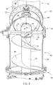
- a skid 78 is provided as an alternative or in addition to the additional conveyor element 60, which is provided in the transition housing 48 the first screw conveyor 46 is arranged adjacent to and spaced from the second screw conveyor 50.
- the runner 78 has a leading edge 80 which is arranged in the plane orthogonal to the axis of rotation of the shaft 58 radially to the axis of rotation of the shaft 58 and approximately parallel to the axis of rotation of the shaft 70.
- the position and orientation of the leading edge 80 could deviate from the position shown and, for example, viewed in the circumferential direction, could be inclined inwards or outwards and / or inclined upwards or downwards from the horizontal plane.
- the runner 78 extends from the wall 64 to the cover 74. From the leading edge 80, the runner 78 extends helically to a trailing edge 82 which is approximately rectilinear and orthogonal to the adjacent wall 64.
- the position and orientation of the trailing edge 82 could deviate from the position shown and, for example, viewed in the vertical direction, be more or less inclined inwards or outwards than shown in the drawing and / or inclined more or less upwards or downwards in the horizontal direction.
- the edge 82 At the radially outer end of the edge 82 there is also an (optional) trailing nose 84 adjacent to the wall 64, which could alternatively or additionally also be attached radially on the inside.
- the runner 78 forms a relatively short helix, which is directed towards the screw conveyors 56 and 68 and has a larger pitch than the screw conveyors 56, 68.
- the runner 78 At the front edge 80, the runner 78 is still slightly bent, so that it has a lower slope in a leading area than in the rest of the part.
Landscapes
- Engineering & Computer Science (AREA)
- Mechanical Engineering (AREA)
- Life Sciences & Earth Sciences (AREA)
- Environmental Sciences (AREA)
- Threshing Machine Elements (AREA)
- Screw Conveyors (AREA)
Description
- Die Erfindung betrifft einen Schneckenfördererzusammenbau, der Folgendes umfasst:
- einen ersten Schneckenförderer mit einem ersten Gehäuse und einer darin angeordneten, ersten Förderschnecke,
- einen zweiten Schneckenförderer mit einem zweiten Gehäuse und einer darin angeordneten, zweiten Förderschnecke, und
- einem Übergangsgehäuse, an das sich das erste Gehäuse und das zweite Gehäuse unter Bildung eines Übergangswinkels anschließen,
- wobei die erste Förderschnecke stromauf der zweiten Förderschnecke angeordnet ist und im Übergangsgehäuse eine feststehende Kufe angebracht ist, welche angeordnet ist, das Fördergut von der ersten Förderschnecke zur zweiten Förderschnecke zu leiten, sowie einen damit ausgestatteten Mähdrescher.
- Landwirtschaftliche Mähdrescher werden bei der Ernte von Körnerfrüchten eingesetzt, um auf einem Feld angebaute Pflanzen zu ernten und zu dreschen. Das ausgedroschene Erntegut wird anschließend noch durch eine Trenneinrichtung bearbeitet. Das im Dresch- und Trennprozess gewonnene Korn wird in einer Reinigungseinrichtung gereinigt und in einem Korntank abgelegt, aus dem es schließlich auf ein Transportfahrzeug überladen wird.
- Zum Entladen des Korntanks bedient man sich üblicherweise eines Schneckenförderers, der um die Hochachse zwischen einer ausgeschwenkten Entladeposition, in der er sich quer zur Vorwärtsrichtung erstreckt, und einer nach hinten eingeschwenkten Transportposition schwenkbeweglich ist. Um bei einer gegebenen Höhe des Korntankbodens das Abgabeende des Schneckenförderers möglichst hoch über dem Boden zu halten (und somit auch mit relativ hoch bauenden Transportfahrzeugen unter das Abgabeende des Schneckenförderers fahren zu können), umfassen gebräuchliche Schneckenförderer (s.
EP 1 186 222 A1 ) einen ersten, sich näherungsweise vertikal nach oben erstreckenden Abschnitt, an welchen sich ein zweiter, horizontaler Abschnitt anschließt. Die beiden Abschnitte sind durch ein um etwa 90° abgewinkeltes Übergangsgehäuse untereinander verbunden, in welchen die Förderschnecken der beiden Abschnitte durch Antriebselemente (Gelenkwellen) untereinander trieblich gekoppelt werden. - Zwischen der ersten Förderschnecke und der zweiten Förderschnecke entsteht im Übergangsgehäuse ein gewisser räumlicher Abstand, der nicht durch aktiv angetriebene Förderelemente überstrichen wird. Weiterhin erfolgt eine Umlenkung des Erntegutflusses und zudem bei vielen Ausführungsformen eine Verengung des Querschnitts vom ersten zum zweiten Schneckenförderer hin. Diese Umstände können bei gewissen Erntegutbedingungen (z.B. bei relativ feuchtem Korn oder kleinen Kornabmessungen, die ein niedriges Verhältnis zwischen Volumen und somit Masse und Oberfläche bedingen, wie bei Grassamen, und sich daher nicht gut durch das Übergangsgehäuse werfen lassen) zu Übergabeproblemen und zu Verstopfungen führen.
- Gebräuchliche Lösungen für dieses Problem (
AT 365 401 B GB 1 038 037 A EP 0 274 761 A1 undUS 4 093 087 A ) sehen an einer Verbindungswelle zwischen den beiden Förderschnecken angebrachte Förderelemente in Form von Flügeln, Paddeln, o.ä. vor. Sie führen jedoch nicht in allen Fällen zu einem befriedigenden Förderverhalten und verhindern zudem, dass die Verbindungswelle mit ihren Gelenken abgedeckt werden kann. Das geförderte Korn kommt demnach auch in Kontakt mit dem Schmiermittel der Gelenke und kann durch die sich relativ zueinander bewegenden Elemente der Gelenke mechanisch beschädigt werden. - Die als gattungsbildend angesehene
US 4 037 745 A zeigt einen Mähdrescher mit einem Entladeschneckenförderer, der sich aus einem vertikalen und einem horizontalen Teil zusammensetzt. In einem Übergangsgehäuse zwischen beiden Teilen ist ein gekrümmtes Ablenkblech angeordnet, um das Korn abzulenken. Das Ablenkblech erstreckt sich parallel zur Achse des horizontalen Teils des Schneckenförderers und ist in der dazu orthogonalen Ebene gekrümmt, d.h. bildet praktisch eine kurvenförmige Innenwand des Übergangsgehäuses. - Die
EP 2 200 914 B1 zeigt einen Überkehrförderer, der sich aus einem horizontalen und einem ansteigenden Teil zusammensetzt. Die Wendel des horizontalen Schneckenförderers ist endseitig mit einem Bereich ausgestattet, der eine größere Steigung als die übrige Wendel aufweist. - Die Aufgabe der vorliegenden Erfindung wird darin gesehen, einen gegenüber dem Stand der Technik verbesserten Schneckenförderer und damit ausgestatteten Mähdrescher bereit zu stellen.
- Diese Aufgabe wird erfindungsgemäß durch die Lehre der Patentansprüche 1 und 10 gelöst, wobei in den weiteren Patentansprüchen Merkmale aufgeführt sind, die die Lösung in vorteilhafter Weise weiterentwickeln.
- Ein Schneckenfördererzusammenbau zum Transport von Fördergut in Form von granularem Material (wie beispielsweise Korn) umfasst einen ersten Schneckenförderer mit einem ersten Gehäuse und einer darin angeordneten, ersten Förderschnecke, einen zweiten Schneckenförderer mit einem zweiten Gehäuse und einer darin angeordneten, zweiten Förderschnecke, und ein Übergangsgehäuse, an das sich das erste Gehäuse und das zweite Gehäuse unter Bildung eines Übergangswinkels anschließen. Die erste Förderschnecke ist stromauf der zweiten Förderschnecke angeordnet, d.h. sie ist derart antreibbar, dass sie ihr Fördergut in das Übergangsgehäuse fördert, aus dem es von der zweiten Förderschnecke übernommen wird. Im Übergangsgehäuse ist eine feststehende Kufe angebracht, welche angeordnet ist, das Fördergut von der ersten Förderschnecke zur zweiten Förderschnecke zu leiten. Die Kufe umfasst eine bezüglich der Flussrichtung des Förderguts vordere Kante, die sich in einer orthogonal zur Drehachse der ersten Förderschnecke verlaufenden Ebene zumindest näherungsweise radial zur Drehachse der ersten Förderschnecke erstreckt.
- Die Kufe ist demnach als passives Element im Übergangsgehäuse angeordnet und leitet das Fördergut von der ersten Förderschnecke zur zweiten Förderschnecke.
- Zusätzlich kann an der dem Übergangsgehäuse unmittelbar benachbarten Wendel der ersten Förderschnecke ein zusätzliches Förderelement befestigt sein. Das Förderelement verbessert das Abgabeverhalten des ersten Schneckenförderers.
- Gemäß einer bevorzugten Ausführungsform ist im Übergangsgehäuse eine (üblicherweise eine Gelenkwelle umfassende) Antriebsverbindung zur trieblichen Kopplung der ersten und zweiten Förderschnecke vorgesehen, welche durch eine Abdeckung gegenüber dem Innenraum des Übergangsgehäuses abgeschirmt werden kann.
- Die Kufe kann sich von der vorlaufenden Kante aus wendelförmig, mit einer der ersten Förderschnecke entgegen gesetzten Steigung, zu einer rückwärtigen Kante erstrecken. Die Steigung der Kufe kann größer als die Steigung der ersten Förderschnecke sein. Die rückwärtige Kante der Kufe kann sich zumindest näherungsweise orthogonal zur benachbarten Innenwand des konkav gewölbten Übergangsgehäuses erstrecken. Die Kufe kann sich zwischen der Innenwand des Übergangsgehäuses und der Abdeckung erstrecken und/oder an der dem zweiten Schneckenförderer abgewandten Seite des Übergangsgehäuses angebracht sein.
- Das zusätzliche Förderelement kann durch einen rampenartigen Wendelabschnitt gebildet werden, dessen Steigung größer als die Steigung der ersten Förderschnecke ist.
- Der erfindungsgemäße Schneckenfördererzusammenbau kann an einem Mähdrescher zur Entleerung des Korntanks dienen. Es wäre auch denkbar, ihn zur Befüllung des Korntanks einzusetzen oder an einer beliebigen anderen Maschine, in der Korn oder anderes granulares Material gefördert wird, wie zur Entleerung eines Abtankwagens oder an einem beliebigen anderen Förderer für granulares Material insbesondere in Form von ganzem oder zerkleinerten Korn, wie er beispielsweise in mobilen oder stationären Anlagen zur Kornbearbeitung verwendet wird (z.B. Getreidemühlen oder -zerkleinerer oder Reinigungsanlagen für Getreide).
- In den Zeichnungen ist ein nachfolgend näher beschriebenes Ausführungsbeispiel der Erfindung dargestellt. Es zeigt:
- Fig. 1
- eine schematische seitliche Ansicht eines Mähdreschers,
- Fig. 2
- eine perspektivische seitliche Ansicht eines als Korntankentladeförderer vorgesehenen Schneckenfördererzusammenbaus, und
- Fig. 3
- eine perspektivische Vorderansicht des Schneckenfördererzusammenbaus.
- Die
Figur 1 zeigt eine selbstfahrende Erntemaschine in Form eines Mähdreschers 10 mit einem Fahrgestell 12, das sich über angetriebene vordere Räder 14 und lenkbare rückwärtige Räder 16 auf dem Boden abstützt und von diesen fortbewegt wird. Die Räder 14, 16 werden mittels nicht gezeigter Antriebsmittel in Drehung versetzt, um den Mähdrescher 10 z. B. über ein abzuerntendes Feld zu bewegen. Im Folgenden beziehen sich Richtungsangaben, wie vorn und hinten, auf die Fahrtrichtung V des Mähdreschers 10 im Erntebetrieb, die in derFigur 1 nach links verläuft. - An den vorderen Endbereich des Mähdreschers 10 ist ein Erntevorsatz 18 in Form eines Schneidwerks abnehmbar angeschlossen, um beim Erntebetrieb Erntegut in Form von Getreide oder andere, dreschbare Halmfrüchten von dem Feld zu ernten und es nach oben und hinten durch einen Schrägfördererzusammenbau 20 einem Axialdreschwerk 22 zuzuführen. Das im Axialdreschwerk 22 durch Dreschkörbe und Roste hindurchtretende, Körner und Verunreinigungen enthaltende Gemisch gelangt in eine Reinigungseinrichtung 26. Durch die Reinigungseinrichtung 26 gereinigtes Getreide wird mittels einer Körnerschnecke 28 einem Körnerelevator 30 zugeführt, der es in einen Korntank 32 befördert. Das gereinigte Getreide aus dem Korntank 32 kann durch ein Entladesystem mit einer Querschnecke 34 und einem als Schneckenfördererzusammenbau 36 ausgeführten Entladeförderer entladen werden. Die vom Axialdreschwerk 22 abgegebenen Erntegutreste werden mittels einer Fördertrommel 40 einem Strohhäcksler 42 zugeführt, der sie zerkleinert und über die Breite des Schneidwerks 18 über das Feld verteilt. Die genannten Systeme werden mittels eines Verbrennungsmotors angetrieben und von einem Bediener aus einer Fahrerkabine 38 heraus kontrolliert und gesteuert. Das dargestellte Axialdreschwerk 22 mit einem oder mehreren axialen Dresch- und Trennrotoren ist nur ein Ausführungsbeispiel und könnte beispielsweise durch ein Tangentialdreschwerk einer oder mehreren Dreschtrommeln und nachfolgendem Strohschüttler oder Trennrotor(en) ersetzt werden.
- Der Schneckenfördererzusammenbau 36 umfasst einen sich von der Querförderschnecke 34 nach oben erstreckenden, unteren Teil 44, der starr am Fahrgestell 12 abgestützt ist. An einer Drehlagerung 54 (vgl.
EP 1 186 222 A1 ) ist der obere Teil des Schneckenfördererzusammenbaus 36 um die Hochachse drehbar am unteren Teil 44 abgestützt. Der obere Teil des Schneckenfördererzusammenbaus 36 kann durch einen nicht gezeigten Aktor gegenüber der Drehlagerung 54 um die Hochachse verschwenkt werden, um den Schneckenfördererzusammenbau 36 von der inFigur 1 gezeigten Transportposition in eine Betriebsposition zu verschwenken, in der er sich vom Fahrgestell 12 quer zur Fahrtrichtung nach außen erstreckt, um ein Überladen von Korn aus dem Korntank 32 auf ein Transportfahrzeug zu ermöglichen. - Der obere Teil des Schneckenfördererzusammenbaus 36 umfasst einen sich zumindest näherungsweise vertikal nach oben erstreckenden, ersten Schneckenförderer 46, ein Übergangsgehäuse 48 und einen sich zumindest näherungsweise horizontal erstreckenden, zweiten Schneckenförderer 50, der bis sich zu einem äußeren Abgabeende 52 des Schneckenfördererzusammenbaus 36 erstreckt.
- Die
Figur 2 zeigt den ersten Schneckenförderer 46, das Übergangsgehäuse 48 und den proximalen (dem Mähdrescher 10 benachbarten) Teil des zweiten Schneckenförderers 50 von schräg vorn, und dieFigur 3 zeigt sie von vorn. - Der erste Schneckenförderer 46 umfasst ein hohles, zylindrisches (erstes) Gehäuse 62, das an der Drehlagerung 54 befestigt ist. Im ersten Gehäuse 62 ist eine erste, wendelförmige Förderschnecke 56 um eine mittige Welle 58 gelegt. Die Welle 58 kann hohl oder massiv sein und wird von unten her, d.h. von einer mittigen Welle einer im unteren Teil 44 des Schneckenfördererzusammenbaus 36 angeordneten Förderschnecke (in
Figur 1 nicht gezeigt) angetrieben, die mit der ersten Förderschnecke 56 einteilig oder damit gekoppelt sein kann. Die besagte Welle der im unteren Teil 44 des Schneckenfördererzusammenbaus 36 angeordneten Förderschnecke kann ihrerseits durch die Querförderschnecke 34 oder einen separaten Antrieb angetrieben werden, der je nach Bedarf an- und ausgeschaltet werden kann (vgl.EP 2 245 917 A2 ). - Um das Abgabeverhalten der ersten Förderschnecke 56 zu verbessern, ist an der dem Übergangsgehäuse 48 benachbarten Wendel, d.h. kurz vor dem oberen Ende der ersten Förderschnecke 56, ein zusätzliches Förderelement 60 angebracht. Das zusätzliche Förderelement 60 ist rampenartig ausgeführt und wird durch einen Wendelabschnitt gebildet, dessen Steigung größer als die Steigung der ersten Förderschnecke 56 ist.
- Das Übergangsgehäuse 48 wird durch eine bogenförmig gekrümmte Wand 64 gebildet. Die Wand 64 kann, wie in den
Figuren 2 und3 gezeigt, mit dem ersten Gehäuse 62 einteilig geformt sein, z.B. als Guss- oder Schweiß- oder Pressteil, oder davon getrennt und durch eine Schweiß- oder Flanschverbindung damit gekoppelt werden. Der Durchmesser des zweiten Schneckenförderers 50 kann kleiner als jener des ersten Schneckenförderers 46 sein. - Der zweite Schneckenförderer 50 umfasst ein hohles, zylindrisches (zweites) Gehäuse 66, das über eine Flanschverbindung 72 mit der Wand 64 des Übergangsgehäuses 48 verbunden ist. Es wäre auch denkbar, das zweite Gehäuse 66 einteilig mit dem Übergangsgehäuse 48 auszuführen. Im zweiten Gehäuse 66 ist eine zweite, wendelförmige Förderschnecke 68 um eine mittige Welle 70 gelegt. Die Welle 70 kann hohl oder massiv sein und über eine im Übergangsgehäuse 48 angeordnete Antriebsverbindung, die durch eine Abdeckung 74 gegenüber dem Innenraum des Übergangsgehäuses 48 abgeschirmt wird (und daher in den
Figuren 2 und3 nicht zu sehen ist) von unten der Welle 58 her angetrieben. Die Antriebsverbindung kann in an sich bekannter Weise eine Gelenkwelle umfassen. Die Abdeckung 74 ist durch Bolzen 76, die sich radial zur ersten Welle 58 und zur zweiten Welle 70 erstrecken, an gegenüberliegenden Bereichen der Wand 64 des Übergangsgehäuses 48 festgelegt. Es wäre denkbar, anstelle des beschriebenen Antriebs der Welle 58 von der im unteren Teil 44 des Schneckenfördererzusammenbaus 36 angeordneten Förderschnecke her die Welle 58 oder die Welle 70 durch einen anderen Antrieb anzutreiben. - Um den insbesondere bei feuchtem oder feinkörnigem Fördermaterial gelegentlich problematischen Übergang vom ersten Schneckenförderer 46 zum zweiten Schneckenförderer 50 durch das nicht mit aktiv angetriebenen Förderelementen ausgestattete Übergangsgehäuse 48 zu verbessern, ist alternativ oder zusätzlich zum zusätzlichen Förderelement 60 eine Kufe 78 vorgesehen, die im Übergangsgehäuse 48 dem ersten Schneckenförderer 46 benachbart und vom zweiten Schneckenförderer 50 beabstandet angeordnet ist. Die Kufe 78 hat eine vorlaufende Kante 80, die in der orthogonal zur Drehachse der Welle 58 liegenden Ebene radial zur Drehachse der Welle 58 und etwa parallel zur Drehachse der Welle 70 angeordnet ist. Die Lage und Orientierung der vorlaufenden Kante 80 könnte von der gezeigten Position abweichen und beispielsweise in Umfangsrichtung betrachtet nach innen oder außen geneigt sein und/oder aus der horizontalen Ebene nach oben oder unten geneigt sein. Die Kufe 78 erstreckt sich von der Wand 64 bis zur Abdeckung 74. Von der vorlaufenden Kante 80 aus erstreckt sich die Kufe 78 wendelförmig zu einer nachlaufenden Kante 82, die etwa geradlinig und orthogonal zur benachbarten Wand 64 verläuft. Die Lage und Orientierung der nachlaufenden Kante 82 könnte von der gezeigten Position abweichen und beispielsweise in vertikaler Richtung betrachtet mehr oder weniger als zeichnerisch dargestellt nach innen oder außen geneigt sein und/oder in horizontaler Richtung mehr oder weniger weit nach oben oder unten geneigt sein. Am radial äußeren Ende der Kante 82 schließt sich der Wand 64 benachbart noch eine (optionale) nachlaufende Nase 84 an, die alternativ oder zusätzlich auch radial innen angebracht sein könnte. Die Kufe 78 bildet eine den Förderschnecken 56 und 68 entgegen gerichtete, relativ kurze Wendel, die eine größere Steigung als die Förderschnecken 56, 68 aufweist. An der vorderen Kante 80 ist die Kufe 78 noch geringfügig abgeknickt, sodass sie in einem vorlaufenden Bereich eine geringere Steigung als im übrigen Teil aufweist.
Claims (10)
- Schneckenfördererzusammenbau (36), umfassend:einen ersten Schneckenförderer (46) mit einem ersten Gehäuse (62) und einer darin angeordneten, ersten Förderschnecke (56),einen zweiten Schneckenförderer (50) mit einem zweiten Gehäuse (66) und einer darin angeordneten, zweiten Förderschnecke (68), undeinem Übergangsgehäuse (48), an das sich das erste Gehäuse (62) und das zweite Gehäuse (66) unter Bildung eines Übergangswinkels anschließen,wobei die erste Förderschnecke (56) stromauf der zweiten Förderschnecke (68) angeordnet ist und im Übergangsgehäuse (48) eine feststehende Kufe (78) angebracht ist, welche angeordnet ist, das Fördergut von der ersten Förderschnecke (56) zur zweiten Förderschnecke (68) zu leiten,dadurch gekennzeichnet, dass die Kufe (78) eine bezüglich der Flussrichtung des Förderguts vordere Kante (80) umfasst, die sich in einer orthogonal zur Drehachse der ersten Förderschnecke (56) verlaufenden Ebene zumindest näherungsweise radial zur Drehachse der ersten Förderschnecke (56) erstreckt.
- Schneckenfördererzusammenbau (36) nach Anspruch 1, wobei an der dem Übergangsgehäuse (48) unmittelbar benachbarten Wendel der ersten Förderschnecke (56) ein zusätzliches Förderelement (60) angebracht ist.
- Schneckenfördererzusammenbau (36) nach Anspruch 1 oder 2, mit einer im Übergangsgehäuse (48) angeordneten Antriebsverbindung zur trieblichen Kopplung der ersten und zweiten Förderschnecke (56, 68) und einer die Antriebsverbindung gegenüber dem Innenraum des Übergangsgehäuses (48) abschirmenden Abdeckung (74).
- Schneckenfördererzusammenbau (36) nach einem der Ansprüche 1 bis 3, wobei die Kufe (78) sich von einer vorlaufenden Kante (80) aus wendelförmig, mit einer der ersten Förderschnecke (56) entgegen gesetzten Steigung, zu einer rückwärtigen Kante (82) erstreckt.
- Schneckenfördererzusammenbau (36) nach Anspruch 4, wobei die Steigung der Kufe (78) größer als die Steigung der ersten Förderschnecke (56) ist.
- Schneckenfördererzusammenbau (36) nach einem der Ansprüche 4 oder 5, wobei die rückwärtige Kante (82) der Kufe (78) sich zumindest näherungsweise orthogonal zur benachbarten Innenwand des konkav gewölbten Übergangsgehäuses (48) erstreckt.
- Schneckenfördererzusammenbau (36) nach einem der Ansprüche 1 bis 6, wenn rückbezogen auf Anspruch 3, wobei die Kufe (78) sich zwischen einer Wand (64) des Übergangsgehäuses (48) und der Abdeckung (74) erstreckt.
- Schneckenfördererzusammenbau (36) nach einem der vorhergehenden Ansprüche, wobei die Kufe (78) an der dem zweiten Schneckenförderer (50) abgewandten Seite des Übergangsgehäuses (48) angebracht ist.
- Schneckenfördererzusammenbau (36) nach einem der Ansprüche 2 bis 8, wobei das zusätzliche Förderelement (60) durch einen Wendelabschnitt gebildet wird, dessen Steigung größer als die Steigung der ersten Förderschnecke (56) ist.
- Mähdrescher (10) mit einem Korntank (32) und einem zur Entleerung des Korntanks (32) angeordneten Schneckenfördererzusammenbau (36) nach einem der vorhergehenden Ansprüche.
Applications Claiming Priority (1)
| Application Number | Priority Date | Filing Date | Title |
|---|---|---|---|
| DE102017003738.8A DE102017003738A1 (de) | 2017-04-19 | 2017-04-19 | Schneckenfördererzusammenbau für einen Mähdrescher |
Publications (2)
| Publication Number | Publication Date |
|---|---|
| EP3391725A1 EP3391725A1 (de) | 2018-10-24 |
| EP3391725B1 true EP3391725B1 (de) | 2020-01-22 |
Family
ID=61911420
Family Applications (1)
| Application Number | Title | Priority Date | Filing Date |
|---|---|---|---|
| EP18165896.4A Active EP3391725B1 (de) | 2017-04-19 | 2018-04-05 | Schneckenfördererzusammenbau für einen mähdrescher |
Country Status (3)
| Country | Link |
|---|---|
| US (1) | US10701860B2 (de) |
| EP (1) | EP3391725B1 (de) |
| DE (1) | DE102017003738A1 (de) |
Cited By (1)
| Publication number | Priority date | Publication date | Assignee | Title |
|---|---|---|---|---|
| EP3922095A1 (de) | 2020-06-10 | 2021-12-15 | CLAAS Selbstfahrende Erntemaschinen GmbH | Mähdrescher mit einer entleervorrichtung |
Families Citing this family (11)
| Publication number | Priority date | Publication date | Assignee | Title |
|---|---|---|---|---|
| US10390489B2 (en) * | 2017-11-13 | 2019-08-27 | Optimal Agricultural Equipment Ltd. | Grain cart with air nozzle |
| US11140829B2 (en) * | 2018-09-11 | 2021-10-12 | Unverferth Manufacturing Co., Inc. | Farm implement with folding auger |
| DE102019123623A1 (de) * | 2019-09-04 | 2021-03-04 | Claas Selbstfahrende Erntemaschinen Gmbh | Entleervorrichtung für ein Erntegutaufnahmebehältnis eines landwirtschaftlichen Fahrzeugs |
| DE102020205422A1 (de) | 2020-04-29 | 2021-11-04 | Deere & Company | Schneckenfördererzusammenbau zur Entladung eines Korntanks eines Mähdreschers |
| CN112514640B (zh) * | 2020-10-28 | 2021-11-02 | 宁波财经学院 | 谷物收割机的旋转出料分离装置 |
| CN114249147A (zh) * | 2022-01-25 | 2022-03-29 | 天府重工有限公司 | 一种带有降尘功能的垂直螺旋卸车机 |
| CN115893038B (zh) * | 2022-11-15 | 2025-08-05 | 新兴铸管股份有限公司 | 卸车装置 |
| CN116513018B (zh) * | 2023-06-29 | 2023-09-12 | 黑龙江省红亮农业科技有限公司 | 一种液驱多功能耕整地转运机 |
| DE102023129237A1 (de) | 2023-10-24 | 2025-04-24 | Deere & Company | Getriebezusammenbau mit axial verstellbarem Kegelzahnrad |
| US20250214500A1 (en) * | 2023-12-29 | 2025-07-03 | Cei Equipment Company Llc | Trailers for transporting commodities |
| CN118239214B (zh) * | 2024-05-30 | 2024-08-06 | 达州福斯特科技有限公司 | 一种用于三偏磷酸钠盐生产用上料输送机构 |
Family Cites Families (30)
| Publication number | Priority date | Publication date | Assignee | Title |
|---|---|---|---|---|
| US2783907A (en) * | 1953-10-08 | 1957-03-05 | Allis Chalmers Mfg Co | Adjustable grain bin unloading auger assembly for threshing machines |
| US3159024A (en) | 1962-08-30 | 1964-12-01 | Exxon Research Engineering Co | Apparatus for analyzing irregular motions of machinery |
| US3241657A (en) * | 1964-03-13 | 1966-03-22 | Floyd E Buschbom | Jointed feed conveyor |
| GB1310896A (en) * | 1969-07-25 | 1973-03-21 | Massey Ferguson Gmbh | Grain tank unloading devices |
| US3638812A (en) * | 1970-04-07 | 1972-02-01 | Allis Chalmers Mfg Co | Tilting grain auger |
| US3670913A (en) * | 1971-04-19 | 1972-06-20 | Allis Chalmers Mfg Co | Bin unloader break back system |
| US3872982A (en) * | 1974-06-05 | 1975-03-25 | Sperry Rand Corp | Grain unloading assembly |
| US4037745A (en) * | 1976-02-09 | 1977-07-26 | Deere & Company | Combine grain tank unloading mechanism |
| GB1539608A (en) | 1976-06-29 | 1979-01-31 | Clayson Nv | Harvesting machines |
| AT365401B (de) | 1979-01-25 | 1982-01-11 | Hubert Tuscher & Co | Landwirtschaftlicher wagen, insbesondere anhaenger fuer einen traktor |
| EP0183870B1 (de) * | 1984-12-07 | 1989-09-27 | Deere & Company | Entleerungsvorrichtung für den Sammelbehälter einer Erntemaschine |
| EP0274761B1 (de) | 1987-01-13 | 1991-03-27 | Ford New Holland N.V. | Entleerungsvorrichtung für den Sammelbehälter eines Mähdreschers |
| US5511925A (en) * | 1993-01-07 | 1996-04-30 | Muth; Gordon E. | Bin unloading apparatus |
| SE516935C2 (sv) * | 1999-06-03 | 2002-03-26 | Bmh Marine Ab | Aggregat för transport av bulkgods, skovelorgan för ett sådant aggregat samt lastnings- och lossningsanläggning innefattande ett eller flera sådana aggregat |
| US6248015B1 (en) * | 2000-01-27 | 2001-06-19 | New Holland North America, Inc. | Turret system on a bubble-up auger for an agricultural combine |
| US6669240B1 (en) | 2000-09-12 | 2003-12-30 | Deere & Company | Unloader tube pivot ring mechanism |
| CA2376380C (en) * | 2002-03-12 | 2005-05-10 | Bourgault Industries Ltd. | Pivoting unloading auger |
| US8033377B2 (en) * | 2005-11-10 | 2011-10-11 | Deere & Company | Folding unloading auger engagement assistors |
| US7367881B2 (en) * | 2006-02-10 | 2008-05-06 | Agco Corporation | High capacity combine grain bin unload system |
| GB0717952D0 (en) * | 2007-09-14 | 2007-10-24 | Agco Do Brasil Com E Ind Stria | Auger conveyors |
| US8696292B2 (en) * | 2008-05-30 | 2014-04-15 | Deere & Company | Unloading auger elbow |
| US7862286B2 (en) | 2009-05-01 | 2011-01-04 | Deere & Company | Unloading system for an agricultural harvester |
| US8403128B2 (en) * | 2011-04-13 | 2013-03-26 | Wheelabrator Group, Inc. | Conveyor system support hanger assembly |
| US10214362B2 (en) * | 2011-04-19 | 2019-02-26 | Cnh Industrial America Llc | Grain unloading system |
| US9706713B2 (en) * | 2011-07-25 | 2017-07-18 | Unverferth Manufacturing Company, Inc. | Grain cart with folding auger having adjustable elevation |
| US10426092B2 (en) * | 2011-07-25 | 2019-10-01 | Unverferth Manufacturing Company, Inc. | Dual auger grain cart with adjustable forward reach |
| US9723783B2 (en) * | 2012-05-29 | 2017-08-08 | Cnh Industrial America Llc | Folding auger assembly coupler |
| GB201213562D0 (en) * | 2012-07-31 | 2012-09-12 | Agco As | Granule conveying apparatus |
| US8827782B2 (en) * | 2012-08-31 | 2014-09-09 | Cnh Industrial America Llc | Auger drive coupler assembly having a friction clutch for a combine harvester |
| US10399787B2 (en) * | 2016-03-15 | 2019-09-03 | Deere & Company | Conveyor and conveyor drive for filling a combine grain tank |
-
2017
- 2017-04-19 DE DE102017003738.8A patent/DE102017003738A1/de not_active Withdrawn
-
2018
- 2018-03-08 US US15/915,482 patent/US10701860B2/en active Active
- 2018-04-05 EP EP18165896.4A patent/EP3391725B1/de active Active
Non-Patent Citations (1)
| Title |
|---|
| None * |
Cited By (2)
| Publication number | Priority date | Publication date | Assignee | Title |
|---|---|---|---|---|
| EP3922095A1 (de) | 2020-06-10 | 2021-12-15 | CLAAS Selbstfahrende Erntemaschinen GmbH | Mähdrescher mit einer entleervorrichtung |
| DE102020115392A1 (de) | 2020-06-10 | 2021-12-16 | Claas Selbstfahrende Erntemaschinen Gmbh | Mähdrescher mit einer Entleervorrichtung |
Also Published As
| Publication number | Publication date |
|---|---|
| US10701860B2 (en) | 2020-07-07 |
| EP3391725A1 (de) | 2018-10-24 |
| US20180303032A1 (en) | 2018-10-25 |
| DE102017003738A1 (de) | 2018-10-25 |
Similar Documents
| Publication | Publication Date | Title |
|---|---|---|
| EP3391725B1 (de) | Schneckenfördererzusammenbau für einen mähdrescher | |
| EP2250870B1 (de) | Erntegutrestehäcksel und -verteilanordnung für einen Mähdrescher | |
| EP2250868B1 (de) | Erntegutrestehäcksel und -verteilanordnung für einen Mähdrescher | |
| EP2286655B1 (de) | Erntegutrestehäcksel- und -verteilanordnung für einen Mähdrescher | |
| EP2286654B1 (de) | Erntegutrestehäcksel- und -verteilanordnung für einen Mähdrescher | |
| EP3420803B1 (de) | Dresch- oder separierkorb für die getreideernte | |
| EP2676538A1 (de) | Tangentialdreschwerk mit einer Fördertrommel und einer Dresch- oder Abscheidetrommel | |
| EP2250869B1 (de) | Erntegutrestehäcksel und -verteilanordnung für einen Mähdrescher | |
| EP1020108A1 (de) | Rotor für einen Axialmähdrescher | |
| EP4371396A1 (de) | Erntevorsatz mit mit höhenbeweglicher querförderschnecke | |
| EP2708107B1 (de) | Selbstfahrender Mähdrescher | |
| EP2232976B1 (de) | Erntegutrestehäcksel und -verteilanordnung für einen Mähdrescher | |
| DE102016217609B4 (de) | Mähdrescher mit Strohrutsche und Strohförderer | |
| EP1305999B2 (de) | Maschine zum Mähen von stängelartigem Erntegut | |
| BE1022956B1 (de) | Verfahren und Steuerungseinrichtung zum Betreiben einer Erntemaschine | |
| EP1614340B1 (de) | Querförderschnecke für einen Erntevorsatz | |
| DE102020205422A1 (de) | Schneckenfördererzusammenbau zur Entladung eines Korntanks eines Mähdreschers | |
| DE19916645A1 (de) | Fördererzusammenbau | |
| DE102011017618B4 (de) | Axiale Dresch- und Trenneinrichtung für einen Mähdrescher | |
| DE102016202324B4 (de) | Längenverstellbarer Schneckenfördererzusammenbau für einen Mähdrescher | |
| EP1495668B1 (de) | Axialtrenneinrichtung | |
| EP4338580B1 (de) | Selbstfahrender mähdrescher | |
| DE10232802A1 (de) | Erntemaschine | |
| DE102015212608B4 (de) | Erntegutresteverteileinrichtung für einen Mähdrescher | |
| DE102008040128A1 (de) | Erntegutrestehäcksel und -verteilanordnung für einen Mähdrescher mit einem an die Kontur des Strohhäckslers angepassten Wurfgebläse |
Legal Events
| Date | Code | Title | Description |
|---|---|---|---|
| PUAI | Public reference made under article 153(3) epc to a published international application that has entered the european phase |
Free format text: ORIGINAL CODE: 0009012 |
|
| STAA | Information on the status of an ep patent application or granted ep patent |
Free format text: STATUS: THE APPLICATION HAS BEEN PUBLISHED |
|
| AK | Designated contracting states |
Kind code of ref document: A1 Designated state(s): AL AT BE BG CH CY CZ DE DK EE ES FI FR GB GR HR HU IE IS IT LI LT LU LV MC MK MT NL NO PL PT RO RS SE SI SK SM TR |
|
| AX | Request for extension of the european patent |
Extension state: BA ME |
|
| STAA | Information on the status of an ep patent application or granted ep patent |
Free format text: STATUS: REQUEST FOR EXAMINATION WAS MADE |
|
| 17P | Request for examination filed |
Effective date: 20190424 |
|
| RBV | Designated contracting states (corrected) |
Designated state(s): AL AT BE BG CH CY CZ DE DK EE ES FI FR GB GR HR HU IE IS IT LI LT LU LV MC MK MT NL NO PL PT RO RS SE SI SK SM TR |
|
| GRAP | Despatch of communication of intention to grant a patent |
Free format text: ORIGINAL CODE: EPIDOSNIGR1 |
|
| STAA | Information on the status of an ep patent application or granted ep patent |
Free format text: STATUS: GRANT OF PATENT IS INTENDED |
|
| RIC1 | Information provided on ipc code assigned before grant |
Ipc: B65G 33/14 20060101ALI20190731BHEP Ipc: B65G 33/32 20060101ALI20190731BHEP Ipc: A01D 41/12 20060101AFI20190731BHEP Ipc: B60P 1/40 20060101ALI20190731BHEP |
|
| INTG | Intention to grant announced |
Effective date: 20190904 |
|
| RIN1 | Information on inventor provided before grant (corrected) |
Inventor name: SCHEWES, KARL Inventor name: LOUTZ, ERIC Inventor name: KUNKLER, KAI-MARTIN Inventor name: ALBRECHT, JAKOB Inventor name: BASTIAN, BERND |
|
| GRAS | Grant fee paid |
Free format text: ORIGINAL CODE: EPIDOSNIGR3 |
|
| GRAA | (expected) grant |
Free format text: ORIGINAL CODE: 0009210 |
|
| STAA | Information on the status of an ep patent application or granted ep patent |
Free format text: STATUS: THE PATENT HAS BEEN GRANTED |
|
| AK | Designated contracting states |
Kind code of ref document: B1 Designated state(s): AL AT BE BG CH CY CZ DE DK EE ES FI FR GB GR HR HU IE IS IT LI LT LU LV MC MK MT NL NO PL PT RO RS SE SI SK SM TR |
|
| REG | Reference to a national code |
Ref country code: GB Ref legal event code: FG4D Free format text: NOT ENGLISH |
|
| REG | Reference to a national code |
Ref country code: CH Ref legal event code: EP |
|
| REG | Reference to a national code |
Ref country code: DE Ref legal event code: R096 Ref document number: 502018000642 Country of ref document: DE |
|
| REG | Reference to a national code |
Ref country code: AT Ref legal event code: REF Ref document number: 1226325 Country of ref document: AT Kind code of ref document: T Effective date: 20200215 |
|
| REG | Reference to a national code |
Ref country code: IE Ref legal event code: FG4D Free format text: LANGUAGE OF EP DOCUMENT: GERMAN |
|
| REG | Reference to a national code |
Ref country code: NL Ref legal event code: MP Effective date: 20200122 |
|
| REG | Reference to a national code |
Ref country code: LT Ref legal event code: MG4D |
|
| PG25 | Lapsed in a contracting state [announced via postgrant information from national office to epo] |
Ref country code: RS Free format text: LAPSE BECAUSE OF FAILURE TO SUBMIT A TRANSLATION OF THE DESCRIPTION OR TO PAY THE FEE WITHIN THE PRESCRIBED TIME-LIMIT Effective date: 20200122 Ref country code: FI Free format text: LAPSE BECAUSE OF FAILURE TO SUBMIT A TRANSLATION OF THE DESCRIPTION OR TO PAY THE FEE WITHIN THE PRESCRIBED TIME-LIMIT Effective date: 20200122 Ref country code: PT Free format text: LAPSE BECAUSE OF FAILURE TO SUBMIT A TRANSLATION OF THE DESCRIPTION OR TO PAY THE FEE WITHIN THE PRESCRIBED TIME-LIMIT Effective date: 20200614 Ref country code: NO Free format text: LAPSE BECAUSE OF FAILURE TO SUBMIT A TRANSLATION OF THE DESCRIPTION OR TO PAY THE FEE WITHIN THE PRESCRIBED TIME-LIMIT Effective date: 20200422 Ref country code: NL Free format text: LAPSE BECAUSE OF FAILURE TO SUBMIT A TRANSLATION OF THE DESCRIPTION OR TO PAY THE FEE WITHIN THE PRESCRIBED TIME-LIMIT Effective date: 20200122 |
|
| PG25 | Lapsed in a contracting state [announced via postgrant information from national office to epo] |
Ref country code: IS Free format text: LAPSE BECAUSE OF FAILURE TO SUBMIT A TRANSLATION OF THE DESCRIPTION OR TO PAY THE FEE WITHIN THE PRESCRIBED TIME-LIMIT Effective date: 20200522 Ref country code: SE Free format text: LAPSE BECAUSE OF FAILURE TO SUBMIT A TRANSLATION OF THE DESCRIPTION OR TO PAY THE FEE WITHIN THE PRESCRIBED TIME-LIMIT Effective date: 20200122 Ref country code: LV Free format text: LAPSE BECAUSE OF FAILURE TO SUBMIT A TRANSLATION OF THE DESCRIPTION OR TO PAY THE FEE WITHIN THE PRESCRIBED TIME-LIMIT Effective date: 20200122 Ref country code: BG Free format text: LAPSE BECAUSE OF FAILURE TO SUBMIT A TRANSLATION OF THE DESCRIPTION OR TO PAY THE FEE WITHIN THE PRESCRIBED TIME-LIMIT Effective date: 20200422 Ref country code: GR Free format text: LAPSE BECAUSE OF FAILURE TO SUBMIT A TRANSLATION OF THE DESCRIPTION OR TO PAY THE FEE WITHIN THE PRESCRIBED TIME-LIMIT Effective date: 20200423 Ref country code: HR Free format text: LAPSE BECAUSE OF FAILURE TO SUBMIT A TRANSLATION OF THE DESCRIPTION OR TO PAY THE FEE WITHIN THE PRESCRIBED TIME-LIMIT Effective date: 20200122 |
|
| REG | Reference to a national code |
Ref country code: DE Ref legal event code: R097 Ref document number: 502018000642 Country of ref document: DE |
|
| PG25 | Lapsed in a contracting state [announced via postgrant information from national office to epo] |
Ref country code: EE Free format text: LAPSE BECAUSE OF FAILURE TO SUBMIT A TRANSLATION OF THE DESCRIPTION OR TO PAY THE FEE WITHIN THE PRESCRIBED TIME-LIMIT Effective date: 20200122 Ref country code: DK Free format text: LAPSE BECAUSE OF FAILURE TO SUBMIT A TRANSLATION OF THE DESCRIPTION OR TO PAY THE FEE WITHIN THE PRESCRIBED TIME-LIMIT Effective date: 20200122 Ref country code: LT Free format text: LAPSE BECAUSE OF FAILURE TO SUBMIT A TRANSLATION OF THE DESCRIPTION OR TO PAY THE FEE WITHIN THE PRESCRIBED TIME-LIMIT Effective date: 20200122 Ref country code: SK Free format text: LAPSE BECAUSE OF FAILURE TO SUBMIT A TRANSLATION OF THE DESCRIPTION OR TO PAY THE FEE WITHIN THE PRESCRIBED TIME-LIMIT Effective date: 20200122 Ref country code: CZ Free format text: LAPSE BECAUSE OF FAILURE TO SUBMIT A TRANSLATION OF THE DESCRIPTION OR TO PAY THE FEE WITHIN THE PRESCRIBED TIME-LIMIT Effective date: 20200122 Ref country code: ES Free format text: LAPSE BECAUSE OF FAILURE TO SUBMIT A TRANSLATION OF THE DESCRIPTION OR TO PAY THE FEE WITHIN THE PRESCRIBED TIME-LIMIT Effective date: 20200122 Ref country code: RO Free format text: LAPSE BECAUSE OF FAILURE TO SUBMIT A TRANSLATION OF THE DESCRIPTION OR TO PAY THE FEE WITHIN THE PRESCRIBED TIME-LIMIT Effective date: 20200122 Ref country code: SM Free format text: LAPSE BECAUSE OF FAILURE TO SUBMIT A TRANSLATION OF THE DESCRIPTION OR TO PAY THE FEE WITHIN THE PRESCRIBED TIME-LIMIT Effective date: 20200122 |
|
| PLBE | No opposition filed within time limit |
Free format text: ORIGINAL CODE: 0009261 |
|
| STAA | Information on the status of an ep patent application or granted ep patent |
Free format text: STATUS: NO OPPOSITION FILED WITHIN TIME LIMIT |
|
| PG25 | Lapsed in a contracting state [announced via postgrant information from national office to epo] |
Ref country code: MC Free format text: LAPSE BECAUSE OF FAILURE TO SUBMIT A TRANSLATION OF THE DESCRIPTION OR TO PAY THE FEE WITHIN THE PRESCRIBED TIME-LIMIT Effective date: 20200122 |
|
| 26N | No opposition filed |
Effective date: 20201023 |
|
| PG25 | Lapsed in a contracting state [announced via postgrant information from national office to epo] |
Ref country code: LU Free format text: LAPSE BECAUSE OF NON-PAYMENT OF DUE FEES Effective date: 20200405 Ref country code: FR Free format text: LAPSE BECAUSE OF NON-PAYMENT OF DUE FEES Effective date: 20200430 |
|
| PG25 | Lapsed in a contracting state [announced via postgrant information from national office to epo] |
Ref country code: SI Free format text: LAPSE BECAUSE OF FAILURE TO SUBMIT A TRANSLATION OF THE DESCRIPTION OR TO PAY THE FEE WITHIN THE PRESCRIBED TIME-LIMIT Effective date: 20200122 Ref country code: PL Free format text: LAPSE BECAUSE OF FAILURE TO SUBMIT A TRANSLATION OF THE DESCRIPTION OR TO PAY THE FEE WITHIN THE PRESCRIBED TIME-LIMIT Effective date: 20200122 |
|
| PG25 | Lapsed in a contracting state [announced via postgrant information from national office to epo] |
Ref country code: IE Free format text: LAPSE BECAUSE OF NON-PAYMENT OF DUE FEES Effective date: 20200405 |
|
| PG25 | Lapsed in a contracting state [announced via postgrant information from national office to epo] |
Ref country code: LI Free format text: LAPSE BECAUSE OF NON-PAYMENT OF DUE FEES Effective date: 20210430 Ref country code: CH Free format text: LAPSE BECAUSE OF NON-PAYMENT OF DUE FEES Effective date: 20210430 |
|
| PG25 | Lapsed in a contracting state [announced via postgrant information from national office to epo] |
Ref country code: TR Free format text: LAPSE BECAUSE OF FAILURE TO SUBMIT A TRANSLATION OF THE DESCRIPTION OR TO PAY THE FEE WITHIN THE PRESCRIBED TIME-LIMIT Effective date: 20200122 Ref country code: MT Free format text: LAPSE BECAUSE OF FAILURE TO SUBMIT A TRANSLATION OF THE DESCRIPTION OR TO PAY THE FEE WITHIN THE PRESCRIBED TIME-LIMIT Effective date: 20200122 Ref country code: CY Free format text: LAPSE BECAUSE OF FAILURE TO SUBMIT A TRANSLATION OF THE DESCRIPTION OR TO PAY THE FEE WITHIN THE PRESCRIBED TIME-LIMIT Effective date: 20200122 |
|
| PG25 | Lapsed in a contracting state [announced via postgrant information from national office to epo] |
Ref country code: MK Free format text: LAPSE BECAUSE OF FAILURE TO SUBMIT A TRANSLATION OF THE DESCRIPTION OR TO PAY THE FEE WITHIN THE PRESCRIBED TIME-LIMIT Effective date: 20200122 Ref country code: AL Free format text: LAPSE BECAUSE OF FAILURE TO SUBMIT A TRANSLATION OF THE DESCRIPTION OR TO PAY THE FEE WITHIN THE PRESCRIBED TIME-LIMIT Effective date: 20200122 |
|
| PGFP | Annual fee paid to national office [announced via postgrant information from national office to epo] |
Ref country code: IT Payment date: 20220421 Year of fee payment: 5 |
|
| GBPC | Gb: european patent ceased through non-payment of renewal fee |
Effective date: 20220405 |
|
| PG25 | Lapsed in a contracting state [announced via postgrant information from national office to epo] |
Ref country code: GB Free format text: LAPSE BECAUSE OF NON-PAYMENT OF DUE FEES Effective date: 20220405 |
|
| PG25 | Lapsed in a contracting state [announced via postgrant information from national office to epo] |
Ref country code: IT Free format text: LAPSE BECAUSE OF NON-PAYMENT OF DUE FEES Effective date: 20230405 |
|
| REG | Reference to a national code |
Ref country code: AT Ref legal event code: MM01 Ref document number: 1226325 Country of ref document: AT Kind code of ref document: T Effective date: 20230405 |
|
| PG25 | Lapsed in a contracting state [announced via postgrant information from national office to epo] |
Ref country code: AT Free format text: LAPSE BECAUSE OF NON-PAYMENT OF DUE FEES Effective date: 20230405 |
|
| PG25 | Lapsed in a contracting state [announced via postgrant information from national office to epo] |
Ref country code: AT Free format text: LAPSE BECAUSE OF NON-PAYMENT OF DUE FEES Effective date: 20230405 |
|
| PGFP | Annual fee paid to national office [announced via postgrant information from national office to epo] |
Ref country code: DE Payment date: 20250319 Year of fee payment: 8 |
|
| PGFP | Annual fee paid to national office [announced via postgrant information from national office to epo] |
Ref country code: BE Payment date: 20250428 Year of fee payment: 8 |
|
| PGFP | Annual fee paid to national office [announced via postgrant information from national office to epo] |
Ref country code: AT Payment date: 20260410 Year of fee payment: 5 |