EP3391577B1 - Reference signals for estimating mixed interference - Google Patents
Reference signals for estimating mixed interference Download PDFInfo
- Publication number
- EP3391577B1 EP3391577B1 EP16823071.2A EP16823071A EP3391577B1 EP 3391577 B1 EP3391577 B1 EP 3391577B1 EP 16823071 A EP16823071 A EP 16823071A EP 3391577 B1 EP3391577 B1 EP 3391577B1
- Authority
- EP
- European Patent Office
- Prior art keywords
- reference signals
- subframe
- interference
- pattern
- measuring
- Prior art date
- Legal status (The legal status is an assumption and is not a legal conclusion. Google has not performed a legal analysis and makes no representation as to the accuracy of the status listed.)
- Active
Links
Images


Classifications
-
- H—ELECTRICITY
- H04—ELECTRIC COMMUNICATION TECHNIQUE
- H04L—TRANSMISSION OF DIGITAL INFORMATION, e.g. TELEGRAPHIC COMMUNICATION
- H04L5/00—Arrangements affording multiple use of the transmission path
- H04L5/003—Arrangements for allocating sub-channels of the transmission path
- H04L5/0048—Allocation of pilot signals, i.e. of signals known to the receiver
-
- H—ELECTRICITY
- H04—ELECTRIC COMMUNICATION TECHNIQUE
- H04W—WIRELESS COMMUNICATION NETWORKS
- H04W24/00—Supervisory, monitoring or testing arrangements
- H04W24/08—Testing, supervising or monitoring using real traffic
-
- H—ELECTRICITY
- H04—ELECTRIC COMMUNICATION TECHNIQUE
- H04W—WIRELESS COMMUNICATION NETWORKS
- H04W28/00—Network traffic management; Network resource management
- H04W28/02—Traffic management, e.g. flow control or congestion control
- H04W28/0231—Traffic management, e.g. flow control or congestion control based on communication conditions
- H04W28/0236—Traffic management, e.g. flow control or congestion control based on communication conditions radio quality, e.g. interference, losses or delay
-
- H—ELECTRICITY
- H04—ELECTRIC COMMUNICATION TECHNIQUE
- H04W—WIRELESS COMMUNICATION NETWORKS
- H04W72/00—Local resource management
- H04W72/04—Wireless resource allocation
- H04W72/044—Wireless resource allocation based on the type of the allocated resource
- H04W72/0446—Resources in time domain, e.g. slots or frames
-
- H—ELECTRICITY
- H04—ELECTRIC COMMUNICATION TECHNIQUE
- H04W—WIRELESS COMMUNICATION NETWORKS
- H04W76/00—Connection management
- H04W76/20—Manipulation of established connections
- H04W76/27—Transitions between radio resource control [RRC] states
-
- H—ELECTRICITY
- H04—ELECTRIC COMMUNICATION TECHNIQUE
- H04L—TRANSMISSION OF DIGITAL INFORMATION, e.g. TELEGRAPHIC COMMUNICATION
- H04L5/00—Arrangements affording multiple use of the transmission path
- H04L5/0001—Arrangements for dividing the transmission path
- H04L5/0003—Two-dimensional division
- H04L5/0005—Time-frequency
- H04L5/0007—Time-frequency the frequencies being orthogonal, e.g. OFDM(A) or DMT
-
- H—ELECTRICITY
- H04—ELECTRIC COMMUNICATION TECHNIQUE
- H04L—TRANSMISSION OF DIGITAL INFORMATION, e.g. TELEGRAPHIC COMMUNICATION
- H04L5/00—Arrangements affording multiple use of the transmission path
- H04L5/003—Arrangements for allocating sub-channels of the transmission path
- H04L5/0032—Distributed allocation, i.e. involving a plurality of allocating devices, each making partial allocation
- H04L5/0035—Resource allocation in a cooperative multipoint environment
-
- H—ELECTRICITY
- H04—ELECTRIC COMMUNICATION TECHNIQUE
- H04L—TRANSMISSION OF DIGITAL INFORMATION, e.g. TELEGRAPHIC COMMUNICATION
- H04L5/00—Arrangements affording multiple use of the transmission path
- H04L5/14—Two-way operation using the same type of signal, i.e. duplex
- H04L5/1469—Two-way operation using the same type of signal, i.e. duplex using time-sharing
Definitions
- the present disclosure generally relates to wireless communication and, more particularly, to methods and apparatus for estimating mixed interference profiles between nodes in a network.
- Wireless communication systems are widely deployed to provide various telecommunication services such as telephony, video, data, messaging, and broadcasts.
- Typical wireless communication systems may employ multiple-access technologies capable of supporting communication with multiple users by sharing available system resources (e.g., bandwidth, transmit power).
- multiple-access technologies include code division multiple access (CDMA) systems, time division multiple access (TDMA) systems, frequency division multiple access (FDMA) systems, orthogonal frequency division multiple access (OFDMA) systems, single-carrier frequency divisional multiple access (SC-FDMA) systems, and time division synchronous code division multiple access (TD-SCDMA) systems.
- CDMA code division multiple access
- TDMA time division multiple access
- FDMA frequency division multiple access
- OFDMA orthogonal frequency division multiple access
- SC-FDMA single-carrier frequency divisional multiple access
- TD-SCDMA time division synchronous code division multiple access
- LTE/LTE-Advanced is a set of enhancements to the Universal Mobile Telecommunications System (UMTS) mobile standard promulgated by Third Generation Partnership Project (3GPP). It is designed to better support mobile broadband Internet access by improving spectral efficiency, lower costs, improve services, make use of new spectrum, and better integrate with other open standards using OFDMA on the downlink (DL), SC-FDMA on the uplink (UL), and multiple-input multiple-output (MIMO) antenna technology.
- UMTS Universal Mobile Telecommunications System
- 3GPP Third Generation Partnership Project
- Some wireless communication systems may have a fixed downlink and uplink subframe configuration, as for example described in 3GPP R1-131471 and R1-132199. Accordingly, at a given point in time, cells in the network may be synchronized. It may be desirable for cells to reconfigure the ratio of downlink to uplink subframes in an effort to efficiently manage demands of the network.
- Certain aspects of the present disclosure provide a method for wireless communication by a user equipment (UE).
- the method generally includes receiving information regarding a configuration of at least one subframe for measuring mixed interference between the UE and one or more nodes in a network.
- the configuration specifies a pattern for measuring reference signals by the UE within the at least one subframe.
- the method also includes measuring reference signals according to the pattern.
- the method further includes determining interference between the UE and the one or more nodes, based on the measured reference signals.
- Certain aspects of the present disclosure provide a method for wireless communication by a base station (BS).
- the method generally includes receiving information regarding a configuration of at least one subframe for measuring mixed interference between the BS and one or more nodes in a network.
- the configuration specifies a pattern for measuring reference signals by the BS within the at least one subframe.
- the method also includes measuring reference signals according to the pattern.
- the method further includes determining interference between the BS and the one or more nodes, based on the measured reference signals.
- the apparatus generally includes means for receiving information regarding a configuration of at least one subframe for measuring mixed interference between the UE and one or more nodes in a network.
- the configuration specifies a pattern for measuring reference signals by the UE within the at least one subframe.
- the apparatus also includes means for measuring reference signals according to the pattern.
- the apparatus further includes means for determining interference between the UE and the one or more nodes, based on the measured reference signals.
- the apparatus generally includes means for receiving information regarding a configuration of at least one subframe for measuring mixed interference between the BS and one or more nodes in a network.
- the configuration specifies a pattern for measuring reference signals by the BS within the at least one subframe.
- the apparatus also includes means for measuring reference signals according to the pattern.
- the apparatus further includes means for determining interference between the BS and the one or more nodes, based on the measured reference signals.
- the apparatus generally includes at least one processor and a memory coupled to the at least one processor.
- the at least one processor is configured to receive information regarding a configuration of at least one subframe for measuring mixed interference between the UE and one or more nodes in a network.
- the configuration specifies a pattern for measuring reference signals by the UE within the at least one subframe.
- the at least one processor is also configured to measure reference signals according to the pattern.
- the at least one processor is further configured to determine interference between the UE and the one or more nodes, based on the measured reference signals.
- the apparatus generally includes at least one processor and a memory coupled to the at least one processor.
- the at least one processor is configured to receive information regarding a configuration of at least one subframe for measuring mixed interference between the BS and one or more nodes in a network.
- the configuration specifies a pattern for measuring reference signals by the BS within the at least one subframe.
- the at least one processor is also configured to measure reference signals according to the pattern.
- the at least one processor is further configured to determine interference between the BS and the one or more nodes, based on the measured reference signals.
- the computer executable code generally includes code for receiving, by a UE, information regarding a configuration of at least one subframe for measuring mixed interference between the UE and one or more nodes in a network.
- the configuration specifies a pattern for measuring reference signals by the UE within the at least one subframe.
- the computer executable code also includes code for measuring, by the UE, reference signals according to the pattern, and code for determining, by the UE, interference between the UE and the one or more nodes, based on the measured reference signals.
- the computer executable code generally includes code for_receiving, by a BS, information regarding a configuration of at least one subframe for measuring mixed interference between the BS and one or more nodes in a network.
- the configuration specifies a pattern for measuring reference signals by the BS within the at least one subframe.
- the computer executable code also includes code for measuring, by the BS, reference signals according to the pattern, and code for determining, by the BS, interference between the BS and the one or more nodes, based on the measured reference signals.
- the one or more aspects comprise the features hereinafter fully described and particularly pointed out in the claims.
- the following description and the annexed drawings set forth in detail certain illustrative features of the one or more aspects. These features are indicative, however, of but a few of the various ways in which the principles of various aspects may be employed, and this description is intended to include all such aspects and their equivalents.
- aspects of the present disclosure provide techniques and apparatus (e.g., UE, BS, etc.) for measuring mixed (e.g., DL-to-UL or UL-to-DL) interference between different pairs of nodes (e.g., BS-to-BS, UE-to-UE, etc.) in a network.
- mixed e.g., DL-to-UL or UL-to-DL
- the techniques presented herein provide a frame structure that includes one more subframes for measuring the mixed interference between the different pairs of nodes in the network.
- nodes in the network may use such mixed interference measurement subframes intermittently in between other subframes (e.g., such as data subframes) in order to estimate mixed interference.
- the nodes in the network may determine an amount of interference present between different pairs of nodes, compute (or update) jamming graphs, determine whether to switch an uplink subframe to a downlink subframe, or vice versa, etc.
- processors include microprocessors, microcontrollers, digital signal processors (DSPs), field programmable gate arrays (FPGAs), programmable logic devices (PLDs), state machines, gated logic, discrete hardware circuits, and other suitable hardware configured to perform the various functionality described throughout this disclosure.
- DSPs digital signal processors
- FPGAs field programmable gate arrays
- PLDs programmable logic devices
- state machines gated logic, discrete hardware circuits, and other suitable hardware configured to perform the various functionality described throughout this disclosure.
- One or more processors in the processing system may execute software.
- Software shall be construed broadly to mean instructions, instruction sets, code, code segments, program code, programs, subprograms, software modules, applications, software applications, software packages, routines, subroutines, objects, executables, threads of execution, procedures, functions, etc., whether referred to as software/firmware, middleware, microcode, hardware description language, or otherwise.
- the functions described may be implemented in hardware, software/firmware, or combinations thereof. If implemented in software, the functions may be stored on or encoded as one or more instructions or code on a computer-readable medium.
- Computer-readable media includes computer storage media. Storage media may be any available media that can be accessed by a computer.
- such computer-readable media can comprise RAM, ROM, EEPROM, CD-ROM or other optical disk storage, magnetic disk storage or other magnetic storage devices, or any other medium that can be used to carry or store desired program code in the form of instructions or data structures and that can be accessed by a computer.
- Disk and disc includes compact disc (CD), laser disc, optical disc, digital versatile disc (DVD), floppy disk and Blu-ray disc where disks usually reproduce data magnetically, while discs reproduce data optically with lasers. Combinations of the above should also be included within the scope of computer-readable media.
- CDMA code division multiple access
- TDMA time division multiple access
- FDMA frequency division multiple access
- OFDMA orthogonal FDMA
- SC-FDMA single carrier FDMA
- RAT radio access technology
- UTRA universal terrestrial radio access
- WCDMA wideband CDMA
- cdma2000 covers IS-2000, IS-95 and IS-856 standards.
- IS-2000 is also referred to as 1x radio transmission technology (1xRTT), CDMA2000 1X, etc.
- a TDMA network may implement a RAT such as global system for mobile communications (GSM), enhanced data rates for GSM evolution (EDGE), or GSM/EDGE radio access network (GERAN).
- GSM global system for mobile communications
- EDGE enhanced data rates for GSM evolution
- GERAN GSM/EDGE radio access network
- An OFDMA network may implement a RAT such as evolved UTRA (E-UTRA), ultra mobile broadband (UMB), IEEE 802.11 (Wi-Fi), IEEE 802.16 (WiMAX), IEEE 802.20, Flash-OFDM.RTM., etc.
- E-UTRA evolved UTRA
- UMB ultra mobile broadband
- Wi-Fi IEEE 802.11
- WiMAX IEEE 802.16
- IEEE 802.20 Flash-OFDM.RTM.
- UTRA and E-UTRA are part of universal mobile telecommunication system (UMTS).
- 3GPP long-term evolution (LTE) and LTE-Advanced (LTE-A) are new releases of UMTS that use
- UTRA, E-UTRA, UMTS, LTE, LTE-A and GSM are described in documents from an organization named "3rd Generation Partnership Project” (3GPP).
- cdma2000 and UMB are described in documents from an organization named “3rd Generation Partnership Project 2" (3GPP2).
- the techniques described herein may be used for the wireless networks and RATs mentioned above as well as other wireless networks and RATs.
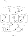
- FIG. 1 illustrates an example deployment in which aspects of the present disclosure may be implemented.
- a BS such, for example, as BS 122 or BS 132 may receive information regarding a configuration of at least one subframe for measuring mixed interference between the BS and one or more nodes (e.g., other BSs, UEs, etc.) in their respective network(s).
- a UE such, for example, as UE 110 may receive information regarding a configuration of at least one subframe for measuring mixed interference between the UE and one or more nodes (e.g., other UEs, BSs, etc.) in their respective network(s).
- Such configuration information may specify a pattern of occurrence of the mixed interference measurement subframe(s), the structure of the mixed interference measurement subframe(s) (e.g., referring to the configuration of the transmission and reception pattern for each of the nodes within the measurement subframe), etc.
- the BS and/or UE may transmit and/or receive reference signals within the measurement subframes according to pattern(s) specified within the configuration information. The BS and/or UE may then determine interference between pairs of nodes in the network(s), based on the reference signals.
- FIG. 1 shows an exemplary deployment in which multiple wireless networks have overlapping coverage.
- a radio access network such as an evolved universal terrestrial radio access network (E-UTRAN) 120 may support LTE and may include a number of evolved Node Bs (eNBs) 122 and other network entities that can support wireless communication for user equipments 110 (UEs).
- An eNB is an entity that communicates with UEs and may also be referred to as a base station, a Node B, or an access point (AP).
- Each eNB 122 may provide communication coverage for a particular geographic area.
- the term "cell" can refer to a coverage area of an eNB and/or an eNB subsystem serving this coverage area.
- a serving gateway (S-GW) 124 may communicate with E-UTRAN 120 and may perform various functions such as packet routing and forwarding, mobility anchoring, packet buffering, initiation of network-triggered services, etc.
- a mobility management entity (MME) 126 may communicate with E-UTRAN 120 and serving gateway 124 and may perform various functions such as mobility management, bearer management, distribution of paging messages, security control, authentication, gateway selection, etc.
- the network entities in LTE are described in 3GPP TS 36.300, entitled “Evolved Universal Terrestrial Radio Access (E-UTRA) and Evolved Universal Terrestrial Radio Access Network (E-UTRAN); Overall description, " which is publicly available.
- a radio access network (RAN) 130 may support GSM and may include a number of base stations (BSs) 132 and other network entities that can support wireless communication for UEs.
- a mobile switching center (MSC) 134 may communicate with the RAN 130 and may support voice services, provide routing for circuit-switched calls, and perform mobility management for UEs located within the area served by MSC 134.
- an inter-working function (IWF) 140 may facilitate communication between MME 126 and MSC 134 (e.g., for 1xCSFB).
- E-UTRAN 120, serving gateway 124, and MME 126 may be part of an LTE network 102.
- RAN 130 and MSC 134 may be part of a GSM network 104.
- FIG. 1 shows only some network entities in the LTE network 102 and the GSM network 104.
- the LTE and GSM networks may also include other network entities that may support various functions and services.
- any number of wireless networks may be deployed in a given geographic area.
- Each wireless network may support a particular RAT and may operate on one or more frequencies.
- a RAT may also be referred to as a radio technology, an air interface, etc.
- a frequency may also be referred to as a carrier, a frequency channel, etc.
- Each frequency may support a single RAT in a given geographic area in order to avoid interference between wireless networks of different RATs.
- a UE 110 may be stationary or mobile and may also be referred to as a mobile station, a terminal, an access terminal, a subscriber unit, a station, etc.
- UE 110 may be a cellular phone, a personal digital assistant (PDA), a wireless modem, a wireless communication device, a handheld device, a laptop computer, a cordless phone, a wireless local loop (WLL) station, etc.
- PDA personal digital assistant
- WLL wireless local loop
- UE 110 may be a Dual SIM dual standby (DSDS) UE.
- UE 110 may search for wireless networks from which it can receive communication services. If more than one wireless network is detected, then a wireless network with the highest priority may be selected to serve UE 110 and may be referred to as the serving network. UE 110 may perform registration with the serving network, if necessary. UE 110 may then operate in a connected mode to actively communicate with the serving network. Alternatively, UE 110 may operate in an idle mode and camp on the serving network if active communication is not required by UE 110.
- UE 110 may be located within the coverage of cells of multiple frequencies and/or multiple RATs while in the idle mode.
- UE 110 may select a frequency and a RAT to camp on based on a priority list.
- This priority list may include a set of frequencies, a RAT associated with each frequency, and a priority of each frequency.
- the priority list may include three frequencies X, Y and Z. Frequency X may be used for LTE and may have the highest priority, frequency Y may be used for GSM and may have the lowest priority, and frequency Z may also be used for GSM and may have medium priority.
- the priority list may include any number of frequencies for any set of RATs and may be specific for the UE location.
- UE 110 may be configured to prefer LTE, when available, by defining the priority list with LTE frequencies at the highest priority and with frequencies for other RATs at lower priorities, e.g., as given by the example above.
- UE 110 may operate in the idle mode as follows. UE 110 may identify all frequencies/RATs on which it is able to find a "suitable” cell in a normal scenario or an "acceptable” cell in an emergency scenario, where "suitable” and “acceptable” are specified in the LTE standards. UE 110 may then camp on the frequency/RAT with the highest priority among all identified frequencies/RATs. UE 110 may remain camped on this frequency/RAT until either (i) the frequency/RAT is no longer available at a predetermined threshold or (ii) another frequency/RAT with a higher priority reaches this threshold.
- This operating behavior for UE 110 in the idle mode is described in 3GPP TS 36.304, entitled “Evolved Universal Terrestrial Radio Access (E-UTRA); User Equipment (UE) procedures in idle mode," which is publicly available.
- E-UTRA Evolved Universal Terrestrial Radio Access
- UE User Equipment
- UE 110 may be able to receive packet-switched (PS) data services from LTE network 102 and may camp on the LTE network while in the idle mode.
- LTE network 102 may have limited or no support for voice-over-Internet protocol (VoIP), which may often be the case for early deployments of LTE networks. Due to the limited VoIP support, UE 110 may be transferred to another wireless network of another RAT for voice calls. This transfer may be referred to as circuit-switched (CS) fallback.
- UE 110 may be transferred to a RAT that can support voice service such as 1xRTT, WCDMA, GSM, etc.
- UE 110 may initially become connected to a wireless network of a source RAT (e.g., LTE) that may not support voice service.
- the UE may originate a voice call with this wireless network and may be transferred through higher-layer signaling to another wireless network of a target RAT that can support the voice call.
- the higher-layer signaling to transfer the UE to the target RAT may be for various procedures, e.g., connection release with redirection, PS handover, etc.
- FIG. 2 is a diagram illustrating an example of an access network 200 in an LTE network architecture, in accordance with aspects of the present disclosure.
- eNBs 204, 208, and/or UEs 206 may receive information regarding a configuration of at least one mixed interference measurement subframe.
- the configuration information may specify a pattern for measuring reference signals by the UE 206 and the eNBs 204, 208 within the mixed interference measurement subframe(s).
- the eNBs 204 and/or 208 and UE 206 may then take action (e.g., measuring reference signals according to the pattern) to determine interference between nodes in the network 200.
- the access network 200 is divided into a number of cellular regions (cells) 202.
- One or more lower power class eNBs 208 may have cellular regions 210 that overlap with one or more of the cells 202.
- a lower power class eNB 208 may be referred to as a remote radio head (RRH).
- the lower power class eNB 208 may be a femto cell (e.g., home eNB (HeNB)), pico cell, or micro cell.
- the macro eNBs 204 are each assigned to a respective cell 202 and are configured to provide an access point to the evolved packet core (EPC), which may include S-GW 124, MME 126, and other entities, for all the UEs 206 in the cells 202.
- EPC evolved packet core
- the eNBs 204 are responsible for all radio related functions including radio bearer control, admission control, mobility control, scheduling, security, and connectivity to the serving gateway 124.
- the modulation and multiple access scheme employed by the access network 200 may vary depending on the particular telecommunications standard being deployed.
- OFDM is used on the DL
- SC-FDMA is used on the UL to support both frequency division duplexing (FDD) and time division duplexing (TDD).
- FDD frequency division duplexing
- TDD time division duplexing
- FDD frequency division duplexing
- TDD time division duplexing
- EV-DO Evolution-Data Optimized
- UMB Ultra Mobile Broadband
- EV-DO and UMB are air interface standards promulgated by the 3rd Generation Partnership Project 2 (3GPP2) as part of the CDMA2000 family of standards and employs CDMA to provide broadband Internet access to mobile stations. These concepts may also be extended to Universal Terrestrial Radio Access (UTRA) employing Wideband-CDMA (W-CDMA) and other variants of CDMA, such as TD-SCDMA; Global System for Mobile Communications (GSM) employing TDMA; and Evolved UTRA (E-UTRA), Ultra Mobile Broadband (UMB), IEEE 802.11 (Wi-Fi), IEEE 802.16 (WiMAX), IEEE 802.20, and Flash-OFDM employing OFDMA.
- UTRA Universal Terrestrial Radio Access
- W-CDMA Wideband-CDMA
- GSM Global System for Mobile Communications
- E-UTRA Evolved UTRA
- UMB Ultra Mobile Broadband
- IEEE 802.11 Wi-Fi
- WiMAX IEEE 802.16
- IEEE 802.20 Flash-OFDM employing OF
- UTRA, E-UTRA, UMTS, LTE and GSM are described in documents from the 3GPP organization.
- CDMA2000 and UMB are described in documents from the 3GPP2 organization.
- the actual wireless communication standard and the multiple access technology employed will depend on the specific application and the overall design constraints imposed on the system.
- the eNBs 204 may have multiple antennas supporting MIMO technology.
- MIMO technology enables the eNBs 204 to exploit the spatial domain to support spatial multiplexing, beamforming, and transmit diversity.
- Spatial multiplexing may be used to transmit different streams of data simultaneously on the same frequency.
- the data steams may be transmitted to a single UE 206 to increase the data rate or to multiple UEs 206 to increase the overall system capacity. This is achieved by spatially precoding each data stream (e.g., applying a scaling of an amplitude and a phase) and then transmitting each spatially precoded stream through multiple transmit antennas on the DL.
- the spatially precoded data streams arrive at the UE(s) 206 with different spatial signatures, which enables each of the UE(s) 206 to recover the one or more data streams destined for that UE 206.
- each UE 206 transmits a spatially precoded data stream, which enables the eNB 204 to identify the source of each spatially precoded data stream.
- Beamforming may be used to focus the transmission energy in one or more directions. This may be achieved by spatially precoding the data for transmission through multiple antennas. To achieve good coverage at the edges of the cell, a single stream beamforming transmission may be used in combination with transmit diversity.
- OFDM is a spread-spectrum technique that modulates data over a number of subcarriers within an OFDM symbol.
- the subcarriers are spaced apart at precise frequencies. The spacing provides "orthogonality" that enables a receiver to recover the data from the subcarriers.
- a guard interval e.g., cyclic prefix
- the UL may use SC-FDMA in the form of a DFT-spread OFDM signal to compensate for high peak-to-average power ratio (PAPR).
- PAPR peak-to-average power ratio
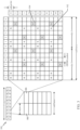
- FIG. 3 is a diagram 300 illustrating an example of a DL frame structure in LTE.
- a frame (10 ms) may be divided into 10 equally sized sub-frames with indices of 0 through 9. Each sub-frame may include two consecutive time slots.
- a resource grid may be used to represent two time slots, each time slot including a resource block.
- the resource grid is divided into multiple resource elements.
- a resource block contains 12 consecutive subcarriers in the frequency domain and, for a normal cyclic prefix in each OFDM symbol, 7 consecutive OFDM symbols in the time domain, or 84 resource elements.
- For an extended cyclic prefix a resource block contains 6 consecutive OFDM symbols in the time domain and has 72 resource elements.
- the DL-RS include Cell-specific RS (CRS) (also sometimes called common RS) 302 and UE-specific RS (UE-RS) 304.
- UE-RS 304 are transmitted only on the resource blocks upon which the corresponding physical DL shared channel (PDSCH) is mapped.
- PDSCH physical DL shared channel
- the number of bits carried by each resource element depends on the modulation scheme. Thus, the more resource blocks that a UE receives and the higher the modulation scheme, the higher the data rate for the UE.
- an eNB may send a primary synchronization signal (PSS) and a secondary synchronization signal (SSS) for each cell in the eNB.
- the primary and secondary synchronization signals may be sent in symbol periods 6 and 5, respectively, in each of subframes 0 and 5 of each radio frame with the normal cyclic prefix (CP).
- the synchronization signals may be used by UEs for cell detection and acquisition.
- the eNB may send a Physical Broadcast Channel (PBCH) in symbol periods 0 to 3 in slot 1 of subframe 0.
- PBCH Physical Broadcast Channel
- the eNB may send a Physical Control Format Indicator Channel (PCFICH) in the first symbol period of each subframe.
- the PCFICH may convey the number of symbol periods (M) used for control channels, where M may be equal to 1, 2 or 3 and may change from subframe to subframe. M may also be equal to 4 for a small system bandwidth, e.g., with less than 10 resource blocks.
- the eNB may send a Physical HARQ Indicator Channel (PHICH) and a Physical Downlink Control Channel (PDCCH) in the first M symbol periods of each subframe.
- the PHICH may carry information to support hybrid automatic repeat request (HARQ).
- the PDCCH may carry information on resource allocation for UEs and control information for downlink channels.
- the eNB may send a Physical Downlink Shared Channel (PDSCH) in the remaining symbol periods of each subframe.
- the PDSCH may carry data for UEs scheduled for data transmission on the downlink.
- the eNB may send the PSS, SSS, and PBCH in the center 1.08 MHz of the system bandwidth used by the eNB.
- the eNB may send the PCFICH and PHICH across the entire system bandwidth in each symbol period in which these channels are sent.
- the eNB may send the PDCCH to groups of UEs in certain portions of the system bandwidth.
- the eNB may send the PDSCH to specific UEs in specific portions of the system bandwidth.
- the eNB may send the PSS, SSS, PBCH, PCFICH, and PHICH in a broadcast manner to all UEs, may send the PDCCH in a unicast manner to specific UEs, and may also send the PDSCH in a unicast manner to specific UEs.
- Each resource element may cover one subcarrier in one symbol period and may be used to send one modulation symbol, which may be a real or complex value.
- Resource elements not used for a reference signal in each symbol period may be arranged into resource element groups (REGs).
- Each REG may include four resource elements in one symbol period.
- the PCFICH may occupy four REGs, which may be spaced approximately equally across frequency, in symbol period 0.
- the PHICH may occupy three REGs, which may be spread across frequency, in one or more configurable symbol periods. For example, the three REGs for the PHICH may all belong in symbol period 0 or may be spread in symbol periods 0, 1, and 2.
- the PDCCH may occupy 9, 18, 36, or 72 REGs, which may be selected from the available REGs, in the first M symbol periods, for example. Only certain combinations of REGs may be allowed for the PDCCH.
- a UE may know the specific REGs used for the PHICH and the PCFICH.
- the UE may search different combinations of REGs for the PDCCH.
- the number of combinations to search is typically less than the number of allowed combinations for the PDCCH.
- An eNB may send the PDCCH to the UE in any of the combinations that the UE will search.
- FIG. 4 is a diagram 400 illustrating an example of an UL frame structure in LTE.
- the available resource blocks for the UL may be partitioned into a data section and a control section.
- the control section may be formed at the two edges of the system bandwidth and may have a configurable size.
- the resource blocks in the control section may be assigned to UEs for transmission of control information.
- the data section may include all resource blocks not included in the control section.
- the UL frame structure results in the data section including contiguous subcarriers, which may allow a single UE to be assigned all of the contiguous subcarriers in the data section.
- a UE may be assigned resource blocks 410a, 410b in the control section to transmit control information to an eNB.
- the UE may also be assigned resource blocks 420a, 420b in the data section to transmit data to the eNB.
- the UE may transmit control information in a physical UL control channel (PUCCH) on the assigned resource blocks in the control section.
- the UE may transmit only data or both data and control information in a physical UL shared channel (PUSCH) on the assigned resource blocks in the data section.
- a UL transmission may span both slots of a subframe and may hop across frequency.
- a set of resource blocks may be used to perform initial system access and achieve UL synchronization in a physical random access channel (PRACH) 430.
- the PRACH 430 carries a random sequence and cannot carry any UL data/signaling.
- Each random access preamble occupies a bandwidth corresponding to six consecutive resource blocks.
- the starting frequency is specified by the network. That is, the transmission of the random access preamble is restricted to certain time and frequency resources. There is no frequency hopping for the PRACH.
- the PRACH attempt is carried in a single subframe (1 ms) or in a sequence of few contiguous subframes and a UE can make only a single PRACH attempt per frame (10 ms).
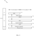
- FIG. 5 is a diagram 500 illustrating an example of a radio protocol architecture for the user and control planes in LTE.
- the radio protocol architecture for the UE and the eNB is shown with three layers: Layer 1, Layer 2, and Layer 3.
- Layer 1 (L1 layer) is the lowest layer and implements various physical layer signal processing functions.
- the L1 layer will be referred to herein as the physical layer 506.
- Layer 2 (L2 layer) 508 is above the physical layer 506 and is responsible for the link between the UE and eNB over the physical layer 506.
- the L2 layer 508 includes a media access control (MAC) sublayer 510, a radio link control (RLC) sublayer 512, and a packet data convergence protocol (PDCP) 514 sublayer, which are terminated at the eNB on the network side.
- MAC media access control
- RLC radio link control
- PDCP packet data convergence protocol
- the UE may have several upper layers above the L2 layer 508 including a network layer (e.g., IP layer) that is terminated at the PDN gateway 118 on the network side, and an application layer that is terminated at the other end of the connection (e.g., far end UE, server, etc.).
- IP layer e.g., IP layer
- the PDCP sublayer 514 provides multiplexing between different radio bearers and logical channels.
- the PDCP sublayer 514 also provides header compression for upper layer data packets to reduce radio transmission overhead, security by ciphering the data packets, and handover support for UEs between eNBs.
- the RLC sublayer 512 provides segmentation and reassembly of upper layer data packets, retransmission of lost data packets, and reordering of data packets to compensate for out-of-order reception due to hybrid automatic repeat request (HARQ).
- HARQ hybrid automatic repeat request
- the MAC sublayer 510 provides multiplexing between logical and transport channels.
- the MAC sublayer 510 is also responsible for allocating the various radio resources (e.g., resource blocks) in one cell among the UEs.
- the MAC sublayer 510 is also responsible for HARQ operations.
- the radio protocol architecture for the UE and eNB is substantially the same for the physical layer 506 and the L2 layer 508 with the exception that there is no header compression function for the control plane.
- the control plane also includes a radio resource control (RRC) sublayer 516 in Layer 3 (L3 layer).
- RRC sublayer 516 is responsible for obtaining radio resources (i.e., radio bearers) and for configuring the lower layers using RRC signaling between the eNB and the UE.
- FIG. 6 is a block diagram of an eNB 610 in communication with a UE 650 in an access network, in accordance with aspects of the present disclosure.
- the base stations 122, 132 and 204 of FIGs. 1 and FIG. 2 may include one or more components of eNB 610 illustrated in FIG. 6 .
- the UEs 110 and 206 illustrated in FIGs 1 and 2 may include one or more components of UE 650 illustrated in FIG. 6 .
- nodes e.g., such as BSs, UEs, etc.
- the nodes may transmit and/or receive reference signals during the mixed interference measurement subframes and determine interference between the nodes and respective other nodes, based on the reference signals.
- the UE 650 may use the configuration information to determine the manner in which it will transmit and/or measure reference signals during the mixed interference measurement subframe, and determine interference between the UE 650 and other UEs, based on the measured reference signals.
- the eNB 610 may use the configuration information to determine the manner in which it will transmit and/or measure reference signals during the mixed interference measurement subframe, and determine interference between the eNB 610 and other eNBs, based on the measured reference signals.
- upper layer packets from the core network are provided to a controller/processor 675.
- the controller/processor 675 implements the functionality of the L2 layer.
- the controller/processor 675 provides header compression, ciphering, packet segmentation and reordering, multiplexing between logical and transport channels, and radio resource allocations to the UE 650 based on various priority metrics.
- the controller/processor 675 is also responsible for HARQ operations, retransmission of lost packets, and signaling to the UE 650.
- the TX processor 616 implements various signal processing functions for the L1 layer (i.e., physical layer).
- the signal processing functions includes coding and interleaving to facilitate forward error correction (FEC) at the UE 650 and mapping to signal constellations based on various modulation schemes (e.g., binary phase-shift keying (BPSK), quadrature phase-shift keying (QPSK), M-phase-shift keying (M-PSK), M-quadrature amplitude modulation (M-QAM)).
- FEC forward error correction
- BPSK binary phase-shift keying
- QPSK quadrature phase-shift keying
- M-PSK M-phase-shift keying
- M-QAM M-quadrature amplitude modulation
- Each stream is then mapped to an OFDM subcarrier, multiplexed with a reference signal (e.g., pilot) in the time and/or frequency domain, and then combined together using an Inverse Fast Fourier Transform (IFFT) to produce a physical channel carrying a time domain OFDM symbol stream.
- the OFDM stream is spatially precoded to produce multiple spatial streams.
- Channel estimates from a channel estimator 674 may be used to determine the coding and modulation scheme, as well as for spatial processing.
- the channel estimate may be derived from a reference signal and/or channel condition feedback transmitted by the UE 650.
- Each spatial stream is then provided to a different antenna 620 via a separate transmitter 618TX.
- Each transmitter 618TX modulates an RF carrier with a respective spatial stream for transmission.
- each receiver 654RX receives a signal through its respective antenna 652. Each receiver 654RX recovers information modulated onto an RF carrier and provides the information to the receiver (RX) processor 656.
- the RX processor 656 implements various signal processing functions of the L1 layer.
- the RX processor 656 performs spatial processing on the information to recover any spatial streams destined for the UE 650. If multiple spatial streams are destined for the UE 650, they may be combined by the RX processor 656 into a single OFDM symbol stream.
- the RX processor 656 then converts the OFDM symbol stream from the time-domain to the frequency domain using a Fast Fourier Transform (FFT).
- FFT Fast Fourier Transform
- the symbols on each subcarrier, and the reference signal, is recovered and demodulated by determining the most likely signal constellation points transmitted by the eNB 610. These soft decisions may be based on channel estimates computed by the channel estimator 658. The soft decisions are then decoded and deinterleaved to recover the data and control signals that were originally transmitted by the eNB 610 on the physical channel. The data and control signals are then provided to the controller/processor 659.
- the controller/processor 659 implements the L2 layer.
- the controller/processor 659 can be associated with a memory 660 that stores program codes and data.
- the memory 660 may be referred to as a computer-readable medium.
- the controller/processor 659 provides demultiplexing between transport and logical channels, packet reassembly, deciphering, header decompression, control signal processing to recover upper layer packets from the core network.
- the upper layer packets are then provided to a data sink 662, which represents all the protocol layers above the L2 layer.
- Various control signals may also be provided to the data sink 662 for L3 processing.
- the controller/processor 659 is also responsible for error detection using an acknowledgement (ACK) and/or negative acknowledgement (NACK) protocol to support HARQ operations.
- ACK acknowledgement
- NACK negative acknowledgement
- a data source 667 is used to provide upper layer packets to the controller/processor 659.
- the data source 667 represents all protocol layers above the L2 layer.
- the controller/processor 659 implements the L2 layer for the user plane and the control plane by providing header compression, ciphering, packet segmentation and reordering, and multiplexing between logical and transport channels based on radio resource allocations by the eNB 610.
- the controller/processor 659 is also responsible for HARQ operations, retransmission of lost packets, and signaling to the eNB 610.
- Channel estimates derived by a channel estimator 658 from a reference signal or feedback transmitted by the eNB 610 may be used by the TX processor 668 to select the appropriate coding and modulation schemes, and to facilitate spatial processing.
- the spatial streams generated by the TX processor 668 are provided to different antenna 652 via separate transmitters 654TX. Each transmitter 654TX modulates an RF carrier with a respective spatial stream for transmission.
- the UL transmission is processed at the eNB 610 in a manner similar to that described in connection with the receiver function at the UE 650.
- Each receiver 618RX receives a signal through its respective antenna 620.
- Each receiver 618RX recovers information modulated onto an RF carrier and provides the information to a RX processor 670.
- the RX processor 670 may implement the L1 layer.
- the controller/processor 675 implements the L2 layer.
- the controller/processor 675 can be associated with a memory 676 that stores program codes and data.
- the memory 676 may be referred to as a computer-readable medium.
- the controller/processor 675 provides demultiplexing between transport and logical channels, packet reassembly, deciphering, header decompression, control signal processing to recover upper layer packets from the UE 650.
- Upper layer packets from the controller/processor 675 may be provided to the core network.
- the controller/processor 675 is also responsible for error detection using an ACK and/or NACK protocol to support HARQ operations.
- the controller/processor 659 may direct the operation at the UE 650.
- the controller/processor 659, RX processor 656, TX processor 668 and/or other processors, components, and/or modules at the UE 650 may perform or direct operations 1200 illustrated in FIG. 12 and/or other processes or operations performed by the UE as described herein.
- the controller/processor 675 may direct the operations at the eNB 610.
- the controller/processor 675, TX processor 616, RX processor 670 and/or other processors, components, and/or modules at the eNB 610 may perform or direct operations 1100 illustrated in FIG. 11 and/or other processes or operations performed by the eNB as described herein.
- FIG. 7 illustrates an example downlink (DL) and uplink (UL) scheduling configuration 700 that may be configured for a network (e.g., LTE).
- DL and UL scheduling is generally implemented with a fixed configuration of DL and UL subframes. This enables synchronization across an entire system deployment. For example, at any given point in time, all of the cells in the network are assigned for downlink communication or uplink communication.
- a network may be configured for downlink transmission on a first subframe 702, fourth subframe 708 and fifth subframe 710, uplink transmission on a third subframe 706, and special subframe configuration (e.g., downlink pilot time slot (DwPTS), uplink pilot time slot (UpPTS), or guard period (GP)) on the second subframe 704.
- special subframe configuration e.g., downlink pilot time slot (DwPTS), uplink pilot time slot (UpPTS), or guard period (GP)
- interference may be limited to DL-to-DL and/or UL-to-UL interference scenarios.
- a DL transmission of one cell may interfere with a DL transmission of another cell.
- a UL transmission from a UE may interfere with another UL transmission from another UE.
- this DL-to-DL or UL-to-UL interference may be mitigated by a UE associating with a cell (e.g., such as a serving cell) based on the strongest downlink signal, e.g., in a small-cell deployment where a network comprises cells of different power classes, or a UE associating with a strong macro cell.
- eNBs and UEs may use enhanced inter-cell interference coordination (eICIC) and advanced receivers for inter-cell interference management (e.g., in DL Heterogeneous Network (HetNet)) in order to mitigate the interference scenarios.
- eICIC enhanced inter-cell interference coordination
- HetNet DL Heterogeneous Network
- power control/shaping may be used in CDMA DL/UL, and SC/O-FDM UL in order to mitigate the interference scenarios.
- intra-cell orthogonalization of multiple DL/UL transmissions within a cell may be used for OFDM DL/SCFDM UL in an effort to mitigate the DL-to-DL and/or UL-to-UL interference.
- any combination of one or more of the above techniques may be used to mitigate the DL-to-DL and/or UL-to-UL interference.
- These techniques may not be able to mitigate interference experienced by nodes (e.g., eNBs, UEs) due to mixed interference, such as UL-to-DL interference and DL-to-UL interference.
- the DL/UL traffic load may not align with the fixed subframe configuration.
- a cell may have a temporary overload in either the UL or DL, it may be desirable to reconfigure one or more subframes from DL to UL or from UL to DL. For example, when the cell is overloaded in the UL direction, the cell may benefit from reconfiguring a nominally DL subframe for UL transmission. Additionally, when the DL load is high, the perceived DL throughput may be low, even though UL resources may be under-utilized.
- the reconfiguration of subframes may cause cells within a network to be unsynchronized, thereby introducing additional interference scenarios.
- the interference may include DL-to-DL and UL-to-UL scenarios described above as well as "mixed interference" including DL-to-UL and UL-to-DL interference.
- An example of UL-to-DL interference may occur when two cell-edge UEs with different serving BSs are arbitrarily close to each other.
- an UL transmission by a first UE may interfere with the DL transmission intended for a second UE. This may cause severe jamming due to the DL-UL mismatch at the two UEs.
- An example of DL-to-UL interference may occur when a second, adjacent, BS's DL transmission is much stronger than a first BS's desired UL signals from its serving UE.
- the first, receiving BS may experience a degradation in sensitivity to the adjacent BS's DL transmission.
- Mixed interference may be particularly serious when the interference is between co-channel or adjacent channel deployments associated with different operators because there may be limited or no dynamic coordination.
- BSs and/or UEs may construct jamming graphs to account for the UL/DL and/or DL/UL mixed interference scenarios.
- a node e.g., BS or UE
- a BS-to-BS jamming graph and a UE-to-UE jamming graph may be constructed.
- Each vertex in a BS-to-BS jamming graph may represent a BS.
- Such a BS may be a near-by BS which may cause interference to the BS maintaining the jamming graph.
- BSi may be connected to BSj in the jamming graph if the maximum interference over thermal (Max_IoT) at BSj due to BSi is greater than the tolerable IoT of BSj (e.g., Max_IoT at BSj due to BSi > BS_Tolerable_IoT of BSj).
- Max_IoT maximum interference over thermal
- the edge from BSi to BSj may be labeled as the transmit (Tx) power/effective isotropic radiated power (EIRP)-backoff needed at BSi to ensure that the IoT at BSj due to BSi becomes equal to the BS_Tolerable_IoT of BSj.
- Tx transmit
- EIRP effective isotropic radiated power
- each vertex in the UE-to-UE jamming graph may represent a UE.
- UEi may be connected to UEj in the jamming graph if the maximum IoT at UEj due to UEi is greater than the tolerable IoT of UEj (e.g., Max_IoT at UEj due to UEi > UE_Tolerable_IoT of UEj).
- the edge from UEi to UEj may be labeled as the Tx power/EIPR-backoff needed at UEi to ensure that the IoT at UEj due to UEi becomes equal to the UE_Tolerable_IoT of UEj.
- the IoT computation for the BS-to-BS jamming graph and UE-to-UE jamming graph may also take into account MIMO beamforming (e.g., the direction of a transmission), receiver nulling, and elevation angular separation.
- the BS and/or UE may construct the UE-to-UE jamming graph.
- a BS may benefit from information regarding the mixed interference profile among nodes (e.g., BSs and UEs) in the network.
- the BS may benefit from knowing the BS-to-BS mixed interference as well as UE-to-UE mixed interference.
- nodes e.g., BSs and UEs
- nodes in the network use reference signals to estimate the channel from BS-to-UE and UE-to-BS. While using reference signals in this manner may be sufficient for synchronized transmission schemes (e.g., all BSs transmitting in DL or all BSs receiving in uplink, as illustrated in FIG.
- these reference signals do not allow nodes to infer the mixed interference profile (e.g., DL-to-UL interference and UL-to-DL interference) for respective nodes (e.g., such as for BS-to-BS or UE-to-UE).
- the mixed interference profile e.g., DL-to-UL interference and UL-to-DL interference
- respective nodes e.g., such as for BS-to-BS or UE-to-UE.
- aspects presented herein provide techniques that allow BSs and UEs to estimate the BS-to-BS and UE-to-UE mixed interference profiles, respectively.
- Techniques presented herein provide frame structures with one or more subframes that can be used for measuring mixed interference.
- FIG 8 illustrates an example frame structure 800 that can be used to measure mixed interference, in accordance with certain aspects.
- mixed interference measurement subframes 802 are used intermittently (e.g., in between data subframes 804).
- a node e.g., BS 122, 132, 204 and/or UE 110, 206) may use the measurement subframes 802 to estimate mixed interference.
- the BS may use its network listen functionality (e.g., turning on its receiver) to estimate BS-BS channel during the mixed interference measurement subframe(s) 802.
- Each BS may have a low duty cycle silencing schedule (e.g., from hundreds of milliseconds to a few seconds).
- the signal-strength from each neighboring BS may be measured during these silent periods.
- a subset of UEs may transmit reference signals (e.g., such as sounding reference signals (SRSs), while other UEs measure the reference signals.
- SRSs sounding reference signals
- Such a configuration may result in different SRS signals being multiplexed over multiple "SRS" channels within a given mixed interference measurement subframe 802.
- the node(s) e.g., BS or UE
- the node(s) can compute (or update) a corresponding jamming graph. For example, pairs of UEs with an edge between them may take turns (e.g., on an order of tens of milliseconds) to transmit/receive each other's SRS.
- the pattern and/or periodicity (e.g., times of occurrence) of the measurement subframes 802 may be determined by the network scheduler and conveyed to BSs and/or UEs through control signaling.
- DL-centric mixed interference measurement subframes e.g., used for measuring BS-BS mixed interference
- UL-centric mixed interference measurement subframes e.g., used for measuring UE-UE mixed interference
- Figure 8A illustrates one example of the different periodicity between DL-centric mixed interference measurement subframes 802A and UL-centric mixed interference measurement subframes 802B.
- DL-centric measurements may occur with a low duty cycle (e.g., in the range of a few hundred milliseconds to a few seconds), based on the mobility of the base station and/or channel characteristics. For example, a low duty cycle may be used (compared to UL-centric measurements) since base stations may be stationary, the channel profile among them may change slowly, etc.
- UL-centric measurements may occur more frequently (e.g., every few tens of milliseconds), based on mobility of UE(s). Using a higher frequency for UL-centric measurements may account for the higher mobility of UEs.
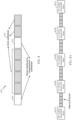
- Figure 9 illustrates an example structure of normal (self-contained) traffic subframes, which include a DL-centric data subframe 900A and a UL-centric data subframe 900B, according to aspects of the present disclosure.
- DL-centric data subframe 900A and UL-centric data subframe 900B are examples of the data subframes 804 illustrated in Figure 8 .
- DL-centric data subframe 900A includes a downlink control portion 902A, a downlink data 904A, a guard period (GP) 906A and an uplink control portion 908A.
- UL-centric data subframe 900B includes a downlink control portion 902B, a guard period 906B, uplink data 904B, and an uplink control portion 908B.
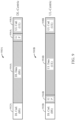
- Figure 10 illustrates an example structure of subframes, such as a DL-centric mixed interference measurement subframe 802A and a UL-centric mixed interference measurement subframe 802B that may be used to measure mixed interference, according to aspects of the present disclosure.
- the mixed interference measurement subframes 802A and 802B both occur with a low duty cycle, e.g., as compared to data traffic subframes 902 and 904.
- the mixed interference measurement subframes 802A and 802B are synchronized across the network.
- DL-centric mixed measurement subframe 802A includes a downlink control portion 1002A, a guard period 1004A, and an uplink control portion 1006A.
- DL-centric mixed interference measurement subframe 802A includes a plurality of slots 1008 for transmitting/receiving channel state information reference signals (CSI-RS) to/from BSs.
- CSI-RS channel state information reference signals
- each BS may transmit on a subset of the CSI-RS slots 1008, and listen on the remaining CSI-RS slots 1008 (e.g., except during a Tx-Rx switch).
- a mixed interference measurement subframe e.g., subframe 802A
- UL-centric measurement subframe 802B similar to UL-centric data subframe 900B, includes a downlink control portion 1002B, a guard period 1004B and an uplink control portion 1006B. However, instead of or in addition to an uplink data portion, UL-centric mixed interference measurement subframe 802B includes a plurality of slots 1010 for transmitting/receiving sounding reference signals (SRSs) to/from UEs. For example, as also described in more detail below, during a UL-centric mixed interference measurement subframe 802B, each UE may transmit on a subset of the SRS slots 1010, and listen on the remaining SRS slots 1010 (e.g., except during a Tx-Rx switch). Although not shown, in general, a mixed interference measurement subframe (e.g., subframe 802B) may also carry a data portion in addition to one or more slots 1010 for SRS.
- SRSs sounding reference signals
- FIG. 11 illustrates example operations 1100 which may be performed by a BS, according to aspects of the present disclosure.
- BS 122, 132 of FIG. 1 and/or BS 204, 208 of FIG. 2 which may include one or more components and/or modules of BS 610 of FIG. 6 may perform the operations 1100.
- the controller/processor 675, memory 676, and/or Tx/Rx 618 may perform aspects described herein.
- the BS receives information regarding a configuration of at least one subframe for measuring mixed interference between the BS and one or more nodes (e.g., such as one or more other BSs) in a network.
- the configuration information may specify a pattern for measuring reference signals by the BS within the at least one subframe.
- the BS measures reference signals according to the pattern.
- the BS determines interference between the BS and the one or more nodes, based on the measured reference signals.
- FIG. 12 illustrates example operations 1200 which may be performed by a UE, according to aspects of the present disclosure.
- UE 110 of FIG. 1 and/or UE 206 of FIG. 2 which may include one or more components and/or modules of UE 650 of FIG. 6 may perform the operations 1200.
- the controller/processor 658, memory 660, and/or Tx/Rx 654 may perform aspects described herein.
- the UE receives information regarding a configuration of at least one subframe for measuring mixed interference between the UE and one or more nodes (e.g., such as one or more other UEs) in a network.
- the configuration information may specify a pattern for measuring reference signals by the UE within the at least one subframe.
- the UE measures reference signals according to the pattern.
- the UE determines interference between the UE and the one or more nodes, based on the measured reference signals.
- the configuration information may specify a pattern of occurrence of the mixed interference measurement subframes (e.g., such as mixed interference measurement subframes 802A and 802B). Additionally or alternatively, the configuration information may specify the measurement frame structure, for each node, within the mixed interference measurement subframe. Such measurement frame structure may include the transmission and reception pattern for each node to follow within the mixed interference measurement subframe.
- the configuration information may be determined by a network and conveyed to BSs and/or UEs via control signaling.
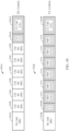
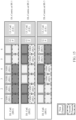
- Figure 13 illustrates one example of a transmission/reception pattern across different BSs (BS1 and BS2) that may be configured for a DL centric measurement subframe, such as DL measurement subframe 802A.
- BS1 transmits CSI-RS (e.g., to BS2) in the first 3 slots 1008 (slots 1, 2 and 3) of the DL-centric measurement subframe, and listens for CSI-RS on the remaining 3 slots 1008 (slots 4, 5 and 6).
- BS2 listens for CSI-RS on the first 3 slots 1008 and transmits CSI-RS (e.g., to BS1) on the remaining 3 slots 1008.
- each BS may transmit CSI-RS to one or more BSs.
- each BS during the slots designated for receiving CSI-RS, may receive CSI-RS from one or more BSs.
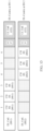
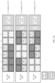
- Figure 14 illustrates an example of a transmission/reception pattern across different UEs (UE1, UE2, and UE3) that may be configured for a UL centric measurement subframe, such as UL measurement subframe 802B.
- UE1 transmits SRS in the first two slots 1010 (e.g., slots 1 and 2) of the UL centric mixed interference measurement subframe and listens for SRS in the remaining slots 1010 (slots 3, 4, 5 and 6) of the UL centric mixed interference measurement subframe 802B.
- each UE2 transmits SRS in the next two slots 1010 (e.g., slots 3 and 4) of the UL centric mixed interference measurement subframe 802B and listens for SRS in the remaining slots 1010 (e.g., slots 1, 2, 5 and 6) of the UL centric mixed interference measurement subframe 802B.
- UE3 transmits SRS in the last two slots 1010 (e.g., slots 5 and 6) of the UL centric mixed interference measurement subframe 802B and listens for SRS in the remaining slots 1010 (e.g., slots 1, 2, 3 and 4) of the UL centric mixed interference measurement subframe 802B.
- each UE may transmit SRS to one or more UEs during their respective slots 1010 designated for transmitting SRS.
- each UE may receive SRS from one or more UEs during their respective slots 1010 designated for receiving SRS.
- the configuration information for UL centric mixed interference measurement subframes may be determined by the BS and signaled to the UE(s) via control signaling, e.g., such as radio resource control (RRC) signaling.
- RRC radio resource control
- the configuration information may also specify, within the transmission/reception pattern, at least one set of frequency resources each node is to use for transmitting/receiving reference signals during the mixed interference measurement subframes 802A, 802B.
- Figures 15 and 16 illustrate an example of a configuration of a DL centric mixed interference measurement subframe and UL centric mixed interference measurement subframe that specifies different frequency resources for transmitting/receiving reference signals, according to aspects of the present disclosure.
- different BSs may use different frequency resources (e.g., a first channel or a second channel) to send CSI-RS at the same time.
- BS1 transmits CSI-RS on the first channel and BS2 transmits CSI-RS on the second channel, while BS3 listens for CSI-RS on both channels.
- BS1 transmits CSI-RS on the first channel and BS3 transmits CSI-RS on the second channel, while BS2 listens for CSI-RS on both channels.
- BS3 transmits CSI-RS on the first channel and BS2 transmits CSI-RS on the second channel, while BS1 listens for CSI-RS on both channels.
- BS1 listens for CSI-RS on both channels.
- a set of BSs can transmit CSI-RS in parallel while the other set listens for CSI-RS.
- different UEs may also use different frequency resources (e.g., a first channel or a second channel) to send SRS at the same time.
- UE1 transmits SRS on the first channel and UE2 transmits SRS on the second channel, while UE3 listens for SRS on both channels.
- UE3 listens for SRS on both channels.
- UE1 transmits SRS on the first channel and UE3 transmits SRS on the second channel, while UE2 listens for SRS on both channels.
- UE3 transmits SRS on the first channel and UE2 transmits SRS on the second channel, while UE1 listens for SRS on both channels. In this manner, a set of UEs can transmit SRS in parallel while the other set listens for SRS.
- the pattern of which UEs transmit reference signals and which UEs listen (or measure) reference signals may depend on whether UEs are served by the same or different base stations. For example, in some cases, UE-to-UE interference may be present when two or more UEs are under different serving base stations, but may not be present when two or more UEs are served by the same base station (e.g., in many cases, the UL-DL subframe configuration can be the same for all UEs within a same cell). Thus, in some embodiments, when UEs are served by the same base station, these UEs may be grouped to transmit together (e.g., possibly using different frequency resources) and grouped to listen (or measure) together.
- UE-to-UE interference may be present when two or more UEs are under different serving base stations, but may not be present when two or more UEs are served by the same base station (e.g., in many cases, the UL-DL subframe configuration can be the same for all UEs within a same cell).
- a mobility event of one or more UEs may trigger the occurrence of a mixed interference measurement subframe and/or a change in configuration (e.g., the transmission/reception pattern of the UEs) of the mixed interference measurement subframe. For example, if two UEs are initially served by the same base station, these UEs may be grouped to transmit and/or receive together, as described above. However, if a handover of the UE from the above base station to another base station occurs, such an event can trigger a change in the configuration of time slots, frequency resources, periodicity of mixed interference measurement subframes, etc. for transmitting/receiving reference signals for the two UEs.
- a change in configuration e.g., the transmission/reception pattern of the UEs
- the nodes transmit and receive reference signals based on the configuration in order to enable measurement of mixed interference.
- BSs may follow a preconfigured schedule involving CSI-RS transmission and/or network listening during measurement subframes to learn about BS-to-BS interference profile(s).
- a subset of UEs can transmit SRS, based on the configuration, while other UEs measure their signals, to learn about UE-to-UE interference profile(s).
- BS-to-BS mixed interference may be measured by each BS and transmitted to other BSs.
- UE-to-UE mixed interference may be measured by each UE from other UEs and may be reported to a BS, for example a UE's serving BS.
- the UE-to-UE measurement may operate in isolation (e.g., without enabling BS-to-BS measurement) or vice versa.
- a BS may send signals to UEs to configure them to do UE-to-UE measurement, but the BS(s) may or may not be configured to perform measurement of BS-to-BS reference signals.
- a network entity may send signals to BS(s) to configure them to do BS-to-BS measurement, but UE(s) may or may not be configured to perform measurement of UE-to-UE reference signals.
- BSs may exchange their own measurements, as well as the reports received from UEs, to other BSs via backhaul or over the air transmission. Based on this information, each BS may construct the mixed interference profile in the form of the jamming graph as described above. For example, the information can be made available to a scheduler (e.g., at the base station), and the BS may use the information to construct the jamming graph.
- the jamming graph may be used to evaluate the impact of a decision to convert the direction of a nominally downlink subframe to an uplink subframe or vice versa.
- Such an approach allows nodes to make scheduling decisions that may minimize the impact of mixed interference in a semi-static manner. Put differently, nodes may not have to negotiate before every slot in order to identify the interference impact of a decision to switch direction of a transmission. Doing so in this manner significantly reduces the overhead associated with performing such a handshake negotiation before every subframe.
- a phrase referring to "at least one of" a list of items refers to any combination of those items, including single members.
- "at least one of: a, b, or c” is intended to cover: a, b, c, a-b, a-c, b-c, and a-b-c, as well as any combination with multiples of the same element (e.g., a-a, a-a-a, a-a-b, a-a-c, a-b-b, a-c-c, b-b, b-b-b, b-b-c, c-c, and c-c-c or any other ordering of a, b, and c).
- determining encompasses a wide variety of actions. For example, “determining” may include calculating, computing, processing, deriving, investigating, looking up (e.g., looking up in a table, a database or another data structure), ascertaining and the like. Also, “determining” may include receiving (e.g., receiving information), accessing (e.g., accessing data in a memory) and the like. Also, “determining” may include resolving, selecting, choosing, establishing and the like.
- a device may have an interface to communicate a frame for transmission or reception.
- a processor may output a frame, via a bus interface, to an RF front end for transmission.
- a device may have an interface to obtain a frame received from another device.
- a processor may obtain (or receive) a frame, via a bus interface, from an RF front end for transmission.
- the methods disclosed herein comprise one or more steps or actions for achieving the described method.
- the method steps and/or actions may be interchanged with one another without departing from the scope of the claims.
- the order and/or use of specific steps and/or actions may be modified without departing from the scope of the claims.
- the various operations of methods described above may be performed by any suitable means capable of performing the corresponding functions.
- the means may include various hardware and/or software/firmware component(s) and/or module(s), including, but not limited to a circuit, an application specific integrated circuit (ASIC), or processor.
- ASIC application specific integrated circuit
- those operations may be performed by any suitable corresponding counterpart means-plus-function components.
- means for receiving, means for measuring and/or means for monitoring may include a receiver, such as RX processor 670, and/or antenna(s) 620 of TX/RX 618 of the base station 610 illustrated in FIG. 6 and/or RX processor 656, and/or antenna(s) 652 of the RX/TX 654 of the user equipment 650 illustrated in FIG. 6 .
- Means for determining, means for measuring, means monitoring, means for applying, means for selecting, means for constructing, and/or means for performing may include one or more processors (or a processing system), such as controller/processor 675, TX processor 616 and/or RX processor 670 of the base station 610 illustrated in FIG.
- Means for signaling, means for providing, means for transmitting, and/or means for indicating may include a transmitter, such as TX processor 616, and/or antenna(s) 620 of TX/RX 618 of the base station 610 illustrated in FIG. 6 , and/or TX processor 668 and/or antenna(s) 652 of RX/TX 654 of the user equipment 650 illustrated in FIG. 6 .
- DSP digital signal processor
- ASIC application specific integrated circuit
- FPGA field programmable gate array
- a general-purpose processor may be a microprocessor, but in the alternative, the processor may be any conventional processor, controller, microcontroller, or state machine.
- a processor may also be implemented as a combination of computing devices, e.g., a combination of a DSP and a microprocessor, a plurality of microprocessors, one or more microprocessors in conjunction with a DSP core, or any other such configuration.
- a software/firmware module may reside in RAM memory, flash memory, ROM memory, EPROM memory, EEPROM memory, phase change memory, registers, hard disk, a removable disk, a CD-ROM, or any other form of storage medium known in the art.
- An exemplary storage medium is coupled to the processor such that the processor can read information from, and write information to, the storage medium.
- the storage medium may be integral to the processor.
- the processor and the storage medium may reside in an ASIC.
- the ASIC may reside in a user terminal.
- the processor and the storage medium may reside as discrete components in a user terminal.
- the functions described may be implemented in hardware, software/firmware, or combinations thereof. If implemented in software/firmware, the functions may be stored on or transmitted over as one or more instructions or code on a computer-readable medium.
- Computer-readable media includes both computer storage media and communication media including any medium that facilitates transfer of a computer program from one place to another.
- a storage media may be any available media that can be accessed by a general purpose or special purpose computer.
- such computer-readable media can comprise RAM, ROM, EEPROM, CD/DVD or other optical disk storage, magnetic disk storage or other magnetic storage devices, or any other medium that can be used to carry or store desired program code means in the form of instructions or data structures and that can be accessed by a general-purpose or special-purpose computer, or a general-purpose or special-purpose processor. Also, any connection is properly termed a computer-readable medium.
- Disk and disc includes compact disc (CD), laser disc, optical disc, digital versatile disc (DVD), floppy disk and Blu-ray disc where disks usually reproduce data magnetically, while discs reproduce data optically with lasers. Combinations of the above should also be included within the scope of computer-readable media.
Landscapes
- Engineering & Computer Science (AREA)
- Signal Processing (AREA)
- Computer Networks & Wireless Communication (AREA)
- Mobile Radio Communication Systems (AREA)
- Monitoring And Testing Of Transmission In General (AREA)
Applications Claiming Priority (3)
| Application Number | Priority Date | Filing Date | Title |
|---|---|---|---|
| US201562267189P | 2015-12-14 | 2015-12-14 | |
| US15/176,347 US10708016B2 (en) | 2015-12-14 | 2016-06-08 | Reference signals for estimating mixed interference |
| PCT/US2016/064214 WO2017105843A1 (en) | 2015-12-14 | 2016-11-30 | Reference signals for estimating mixed interference |
Publications (3)
| Publication Number | Publication Date |
|---|---|
| EP3391577A1 EP3391577A1 (en) | 2018-10-24 |
| EP3391577C0 EP3391577C0 (en) | 2023-08-23 |
| EP3391577B1 true EP3391577B1 (en) | 2023-08-23 |
Family
ID=59020215
Family Applications (1)
| Application Number | Title | Priority Date | Filing Date |
|---|---|---|---|
| EP16823071.2A Active EP3391577B1 (en) | 2015-12-14 | 2016-11-30 | Reference signals for estimating mixed interference |
Country Status (6)
Families Citing this family (8)
| Publication number | Priority date | Publication date | Assignee | Title |
|---|---|---|---|---|
| KR101647643B1 (ko) | 2015-10-23 | 2016-08-11 | 코웨이 주식회사 | 공기 청정기 |
| US9985808B2 (en) | 2016-07-07 | 2018-05-29 | Qualcomm Incorporated | Methods and apparatus for managing interference across operators |
| US11637650B2 (en) * | 2016-07-19 | 2023-04-25 | Nec Corporation | Method and device for performing communication |
| US10624108B2 (en) | 2017-04-05 | 2020-04-14 | Qualcomm Incorporated | Coexistence interference mitigation in wireless systems |
| US20210306127A1 (en) * | 2018-08-09 | 2021-09-30 | Telefonaktiebolaget Lm Ericsson (Publ) | Minimization of base station to base station interference in tdd networks |
| WO2020145880A1 (en) * | 2019-01-11 | 2020-07-16 | Telefonaktiebolaget Lm Ericsson (Publ) | First network node, first ue and methods performed therein for handling communication |
| US11917500B2 (en) * | 2021-03-19 | 2024-02-27 | Ford Global Technologies, Llc | Systems and methods for providing vehicle software updates |
| US12348320B2 (en) | 2021-12-29 | 2025-07-01 | Qualcomm Incorporated | Semi-persistent scheduling timer for reliable transmission |
Family Cites Families (30)
| Publication number | Priority date | Publication date | Assignee | Title |
|---|---|---|---|---|
| US8559908B2 (en) | 2008-06-16 | 2013-10-15 | Qualcomm Incorporated | Jamming graph and its application in network resource assignment |
| KR101674958B1 (ko) * | 2010-03-05 | 2016-11-10 | 엘지전자 주식회사 | 셀 간 간섭을 제어하기 위한 장치 및 방법 |
| CN102595436B (zh) * | 2011-01-13 | 2015-05-27 | 华为技术有限公司 | 一种干扰检测方法、装置和系统 |
| EP3745636B1 (en) * | 2011-02-06 | 2024-09-11 | LG Electronics Inc. | Method and apparatus for inter-cell interference coordination in a wireless communication system |
| US20140038613A1 (en) * | 2011-04-11 | 2014-02-06 | Nokia Siemens Networks Oy | Method and Apparatus |
| WO2012139299A1 (en) * | 2011-04-15 | 2012-10-18 | Nokia Siemens Networks Oy | Nodeb self-tuning |
| KR101767997B1 (ko) * | 2011-06-24 | 2017-08-14 | 삼성전자 주식회사 | 직교 주파수 분할 다중 접속 이동통신 시스템을 기반으로 하는 분산 안테나 시스템에서 하향링크 간섭 측정 방법 및 장치 |
| WO2013025236A1 (en) * | 2011-08-12 | 2013-02-21 | Intel Corporation | System and method of uplink power control in a wireless communication system |
| US9369890B2 (en) * | 2011-11-07 | 2016-06-14 | Ntt Docomo, Inc. | Radio communication system, base station apparatus, mobile terminal apparatus and interference measurement method |
| JP5918507B2 (ja) * | 2011-11-08 | 2016-05-18 | 株式会社Nttドコモ | 無線通信システム、干渉測定方法、無線基地局装置、及びユーザ端末 |
| US9295019B2 (en) | 2011-11-24 | 2016-03-22 | Lg Electronics Inc. | Method for performing device-to-device communication in wireless access system and apparatus for same |
| KR101915133B1 (ko) * | 2011-12-16 | 2018-11-05 | 엘지전자 주식회사 | 무선 접속 시스템에서 채널 상태 정보 측정 방법 및 이를 위한 장치 |
| US9426714B2 (en) * | 2012-03-30 | 2016-08-23 | Qualcomm Incorporated | Wireless communication in view of time varying interference |
| JP5781016B2 (ja) | 2012-06-04 | 2015-09-16 | 株式会社Nttドコモ | 無線基地局、無線通信システム及び無線通信方法 |
| JP6091816B2 (ja) * | 2012-09-11 | 2017-03-08 | 株式会社Nttドコモ | 無線通信システム、基地局装置、移動端末装置、及び干渉測定方法 |
| JP6121124B2 (ja) * | 2012-09-28 | 2017-04-26 | 株式会社Nttドコモ | 無線通信システム、無線通信方法、ユーザ端末及び無線基地局 |
| DK2923510T3 (en) * | 2012-11-26 | 2018-04-03 | Ericsson Telefon Ab L M | Methods and radio network nodes for measuring interference |
| US9955370B2 (en) * | 2013-01-11 | 2018-04-24 | Lg Electronics Inc. | Method and apparatus for controlling interference in wireless communication system |
| WO2014166061A1 (en) | 2013-04-09 | 2014-10-16 | Qualcomm Incorporated | eNB-eNB AND UE-UE MEASUREMENT FOR INTERFERENCE MITIGATION |
| US9980266B2 (en) * | 2013-05-05 | 2018-05-22 | Mariana Goldhamer | Collaborative radio resource allocation in cellular deployments |
| CN103402206A (zh) * | 2013-07-17 | 2013-11-20 | 华为技术有限公司 | 干扰处理方法和基站 |
| KR20150015349A (ko) * | 2013-07-31 | 2015-02-10 | 삼성전자주식회사 | 무선 통신 시스템에서 라디오 접속점 간 조직화 방법 및 장치 |
| US20150089382A1 (en) | 2013-09-26 | 2015-03-26 | Wu-chi Feng | Application context migration framework and protocol |
| US20150189574A1 (en) | 2013-12-26 | 2015-07-02 | Samsung Electronics Co., Ltd. | Methods for dormant cell signaling for advanced cellular network |
| US10020969B2 (en) | 2014-03-14 | 2018-07-10 | Samsung Electronics Co., Ltd. | Methods and apparatus for discovery and measurement in cellular networks |
| WO2015163634A1 (ko) | 2014-04-24 | 2015-10-29 | 엘지전자 주식회사 | 측정 수행 방법 및 단말 |
| WO2016010465A1 (en) * | 2014-07-16 | 2016-01-21 | Telefonaktiebolaget L M Ericsson (Publ) | Apparatus and method for inter cell interference coordination |
| US10149307B2 (en) * | 2014-08-01 | 2018-12-04 | Samsung Electronics Co., Ltd. | Method and apparatus for providing feedback between base transceiver stations through cooperative communication in wireless communication system |
| EP3731589B1 (en) * | 2014-08-06 | 2023-04-12 | InterDigital Patent Holdings, Inc. | Methods and apparatus for determining device-to-device transmission patterns |
| US10244540B2 (en) * | 2015-12-02 | 2019-03-26 | Qualcomm Incorporated | Systems and methods for mixed interference management |
-
2016
- 2016-06-08 US US15/176,347 patent/US10708016B2/en active Active
- 2016-11-30 EP EP16823071.2A patent/EP3391577B1/en active Active
- 2016-11-30 JP JP2018530553A patent/JP7041060B2/ja active Active
- 2016-11-30 CN CN201680072761.5A patent/CN108370299B/zh active Active
- 2016-11-30 KR KR1020187016343A patent/KR102807296B1/ko active Active
- 2016-11-30 WO PCT/US2016/064214 patent/WO2017105843A1/en active Application Filing
Also Published As
| Publication number | Publication date |
|---|---|
| CN108370299B (zh) | 2021-04-16 |
| JP2018538754A (ja) | 2018-12-27 |
| EP3391577C0 (en) | 2023-08-23 |
| EP3391577A1 (en) | 2018-10-24 |
| KR102807296B1 (ko) | 2025-05-13 |
| BR112018011852A2 (pt) | 2018-11-27 |
| KR20180092975A (ko) | 2018-08-20 |
| US10708016B2 (en) | 2020-07-07 |
| US20170170936A1 (en) | 2017-06-15 |
| JP7041060B2 (ja) | 2022-03-23 |
| WO2017105843A1 (en) | 2017-06-22 |
| CN108370299A (zh) | 2018-08-03 |
Similar Documents
| Publication | Publication Date | Title |
|---|---|---|
| US11569875B2 (en) | Uplink multiple-input multiple-output (MIMO) scheduling using beamformed reference signals | |
| EP3391577B1 (en) | Reference signals for estimating mixed interference | |
| EP3414939B1 (en) | User equipment centric mobility (uecm) in radio resource control (rrc) dedicated mode | |
| EP2559310B1 (en) | Method and apparatus for inferring user equipment interference suppression capability from measurements report | |
| US9072000B2 (en) | Power efficient relay discovery protocol | |
| US10462713B2 (en) | Techniques for handover procedure management | |
| US9313012B2 (en) | Apparatus and methods for full duplex communication | |
| US20160029396A1 (en) | Device-to-device for interference mitigation | |
| KR20170089853A (ko) | 무선 통신들에서 탐색 기준 신호들에 기초한 네트워크 식별 | |
| WO2012151426A1 (en) | Determining ue interference during handover in enhanced inter-cell interference coordination | |
| US20150065127A1 (en) | Methods and apparatus for improving connected mode search | |
| BR112018011852B1 (pt) | Sinais de referência para estimativa de interferência mista |
Legal Events
| Date | Code | Title | Description |
|---|---|---|---|
| STAA | Information on the status of an ep patent application or granted ep patent |
Free format text: STATUS: UNKNOWN |
|
| STAA | Information on the status of an ep patent application or granted ep patent |
Free format text: STATUS: THE INTERNATIONAL PUBLICATION HAS BEEN MADE |
|
| PUAI | Public reference made under article 153(3) epc to a published international application that has entered the european phase |
Free format text: ORIGINAL CODE: 0009012 |
|
| STAA | Information on the status of an ep patent application or granted ep patent |
Free format text: STATUS: REQUEST FOR EXAMINATION WAS MADE |
|
| 17P | Request for examination filed |
Effective date: 20180621 |
|
| AK | Designated contracting states |
Kind code of ref document: A1 Designated state(s): AL AT BE BG CH CY CZ DE DK EE ES FI FR GB GR HR HU IE IS IT LI LT LU LV MC MK MT NL NO PL PT RO RS SE SI SK SM TR |
|
| AX | Request for extension of the european patent |
Extension state: BA ME |
|
| DAV | Request for validation of the european patent (deleted) | ||
| DAX | Request for extension of the european patent (deleted) | ||
| STAA | Information on the status of an ep patent application or granted ep patent |
Free format text: STATUS: EXAMINATION IS IN PROGRESS |
|
| 17Q | First examination report despatched |
Effective date: 20210414 |
|
| STAA | Information on the status of an ep patent application or granted ep patent |
Free format text: STATUS: EXAMINATION IS IN PROGRESS |
|
| GRAP | Despatch of communication of intention to grant a patent |
Free format text: ORIGINAL CODE: EPIDOSNIGR1 |
|
| STAA | Information on the status of an ep patent application or granted ep patent |
Free format text: STATUS: GRANT OF PATENT IS INTENDED |
|
| RIC1 | Information provided on ipc code assigned before grant |
Ipc: H04L 5/14 20060101ALN20230226BHEP Ipc: H04W 76/27 20180101ALI20230226BHEP Ipc: H04L 5/00 20060101AFI20230226BHEP |
|
| INTG | Intention to grant announced |
Effective date: 20230317 |
|
| GRAS | Grant fee paid |
Free format text: ORIGINAL CODE: EPIDOSNIGR3 |
|
| GRAA | (expected) grant |
Free format text: ORIGINAL CODE: 0009210 |
|
| STAA | Information on the status of an ep patent application or granted ep patent |
Free format text: STATUS: THE PATENT HAS BEEN GRANTED |
|
| AK | Designated contracting states |
Kind code of ref document: B1 Designated state(s): AL AT BE BG CH CY CZ DE DK EE ES FI FR GB GR HR HU IE IS IT LI LT LU LV MC MK MT NL NO PL PT RO RS SE SI SK SM TR |
|
| RAP3 | Party data changed (applicant data changed or rights of an application transferred) |
Owner name: QUALCOMM INCORPORATED |
|
| REG | Reference to a national code |
Ref country code: GB Ref legal event code: FG4D |
|
| REG | Reference to a national code |
Ref country code: CH Ref legal event code: EP |
|
| REG | Reference to a national code |
Ref country code: IE Ref legal event code: FG4D |
|
| REG | Reference to a national code |
Ref country code: DE Ref legal event code: R096 Ref document number: 602016082169 Country of ref document: DE |
|
| U01 | Request for unitary effect filed |
Effective date: 20230907 |
|
| U07 | Unitary effect registered |
Designated state(s): AT BE BG DE DK EE FI FR IT LT LU LV MT NL PT SE SI Effective date: 20230913 |
|
| U20 | Renewal fee for the european patent with unitary effect paid |
Year of fee payment: 8 Effective date: 20231011 |
|
| PG25 | Lapsed in a contracting state [announced via postgrant information from national office to epo] |
Ref country code: GR Free format text: LAPSE BECAUSE OF FAILURE TO SUBMIT A TRANSLATION OF THE DESCRIPTION OR TO PAY THE FEE WITHIN THE PRESCRIBED TIME-LIMIT Effective date: 20231124 |
|
| PG25 | Lapsed in a contracting state [announced via postgrant information from national office to epo] |
Ref country code: IS Free format text: LAPSE BECAUSE OF FAILURE TO SUBMIT A TRANSLATION OF THE DESCRIPTION OR TO PAY THE FEE WITHIN THE PRESCRIBED TIME-LIMIT Effective date: 20231223 |
|
| PG25 | Lapsed in a contracting state [announced via postgrant information from national office to epo] |
Ref country code: RS Free format text: LAPSE BECAUSE OF FAILURE TO SUBMIT A TRANSLATION OF THE DESCRIPTION OR TO PAY THE FEE WITHIN THE PRESCRIBED TIME-LIMIT Effective date: 20230823 Ref country code: NO Free format text: LAPSE BECAUSE OF FAILURE TO SUBMIT A TRANSLATION OF THE DESCRIPTION OR TO PAY THE FEE WITHIN THE PRESCRIBED TIME-LIMIT Effective date: 20231123 Ref country code: IS Free format text: LAPSE BECAUSE OF FAILURE TO SUBMIT A TRANSLATION OF THE DESCRIPTION OR TO PAY THE FEE WITHIN THE PRESCRIBED TIME-LIMIT Effective date: 20231223 Ref country code: HR Free format text: LAPSE BECAUSE OF FAILURE TO SUBMIT A TRANSLATION OF THE DESCRIPTION OR TO PAY THE FEE WITHIN THE PRESCRIBED TIME-LIMIT Effective date: 20230823 Ref country code: GR Free format text: LAPSE BECAUSE OF FAILURE TO SUBMIT A TRANSLATION OF THE DESCRIPTION OR TO PAY THE FEE WITHIN THE PRESCRIBED TIME-LIMIT Effective date: 20231124 |
|
| PG25 | Lapsed in a contracting state [announced via postgrant information from national office to epo] |
Ref country code: PL Free format text: LAPSE BECAUSE OF FAILURE TO SUBMIT A TRANSLATION OF THE DESCRIPTION OR TO PAY THE FEE WITHIN THE PRESCRIBED TIME-LIMIT Effective date: 20230823 |
|
| PG25 | Lapsed in a contracting state [announced via postgrant information from national office to epo] |
Ref country code: ES Free format text: LAPSE BECAUSE OF FAILURE TO SUBMIT A TRANSLATION OF THE DESCRIPTION OR TO PAY THE FEE WITHIN THE PRESCRIBED TIME-LIMIT Effective date: 20230823 |
|
| PG25 | Lapsed in a contracting state [announced via postgrant information from national office to epo] |
Ref country code: SM Free format text: LAPSE BECAUSE OF FAILURE TO SUBMIT A TRANSLATION OF THE DESCRIPTION OR TO PAY THE FEE WITHIN THE PRESCRIBED TIME-LIMIT Effective date: 20230823 Ref country code: RO Free format text: LAPSE BECAUSE OF FAILURE TO SUBMIT A TRANSLATION OF THE DESCRIPTION OR TO PAY THE FEE WITHIN THE PRESCRIBED TIME-LIMIT Effective date: 20230823 Ref country code: ES Free format text: LAPSE BECAUSE OF FAILURE TO SUBMIT A TRANSLATION OF THE DESCRIPTION OR TO PAY THE FEE WITHIN THE PRESCRIBED TIME-LIMIT Effective date: 20230823 Ref country code: CZ Free format text: LAPSE BECAUSE OF FAILURE TO SUBMIT A TRANSLATION OF THE DESCRIPTION OR TO PAY THE FEE WITHIN THE PRESCRIBED TIME-LIMIT Effective date: 20230823 Ref country code: SK Free format text: LAPSE BECAUSE OF FAILURE TO SUBMIT A TRANSLATION OF THE DESCRIPTION OR TO PAY THE FEE WITHIN THE PRESCRIBED TIME-LIMIT Effective date: 20230823 |
|
| REG | Reference to a national code |
Ref country code: DE Ref legal event code: R097 Ref document number: 602016082169 Country of ref document: DE |
|
| PLBE | No opposition filed within time limit |
Free format text: ORIGINAL CODE: 0009261 |
|
| STAA | Information on the status of an ep patent application or granted ep patent |
Free format text: STATUS: NO OPPOSITION FILED WITHIN TIME LIMIT |
|
| REG | Reference to a national code |
Ref country code: CH Ref legal event code: PL |
|
| PG25 | Lapsed in a contracting state [announced via postgrant information from national office to epo] |
Ref country code: MC Free format text: LAPSE BECAUSE OF FAILURE TO SUBMIT A TRANSLATION OF THE DESCRIPTION OR TO PAY THE FEE WITHIN THE PRESCRIBED TIME-LIMIT Effective date: 20230823 |
|
| PG25 | Lapsed in a contracting state [announced via postgrant information from national office to epo] |
Ref country code: CH Free format text: LAPSE BECAUSE OF NON-PAYMENT OF DUE FEES Effective date: 20231130 |
|
| 26N | No opposition filed |
Effective date: 20240524 |
|
| PG25 | Lapsed in a contracting state [announced via postgrant information from national office to epo] |
Ref country code: MC Free format text: LAPSE BECAUSE OF FAILURE TO SUBMIT A TRANSLATION OF THE DESCRIPTION OR TO PAY THE FEE WITHIN THE PRESCRIBED TIME-LIMIT Effective date: 20230823 Ref country code: CH Free format text: LAPSE BECAUSE OF NON-PAYMENT OF DUE FEES Effective date: 20231130 |
|
| U20 | Renewal fee for the european patent with unitary effect paid |
Year of fee payment: 9 Effective date: 20241011 |
|
| PGFP | Annual fee paid to national office [announced via postgrant information from national office to epo] |
Ref country code: GB Payment date: 20241010 Year of fee payment: 9 |
|
| PGFP | Annual fee paid to national office [announced via postgrant information from national office to epo] |
Ref country code: IE Payment date: 20241028 Year of fee payment: 9 |
|
| PG25 | Lapsed in a contracting state [announced via postgrant information from national office to epo] |
Ref country code: CY Free format text: LAPSE BECAUSE OF FAILURE TO SUBMIT A TRANSLATION OF THE DESCRIPTION OR TO PAY THE FEE WITHIN THE PRESCRIBED TIME-LIMIT; INVALID AB INITIO Effective date: 20161130 |
|
| PG25 | Lapsed in a contracting state [announced via postgrant information from national office to epo] |
Ref country code: HU Free format text: LAPSE BECAUSE OF FAILURE TO SUBMIT A TRANSLATION OF THE DESCRIPTION OR TO PAY THE FEE WITHIN THE PRESCRIBED TIME-LIMIT; INVALID AB INITIO Effective date: 20161130 |