EP3391069B1 - Segmentierung von mr-bildern der quantitativen suszeptibilität - Google Patents
Segmentierung von mr-bildern der quantitativen suszeptibilität Download PDFInfo
- Publication number
- EP3391069B1 EP3391069B1 EP16806191.9A EP16806191A EP3391069B1 EP 3391069 B1 EP3391069 B1 EP 3391069B1 EP 16806191 A EP16806191 A EP 16806191A EP 3391069 B1 EP3391069 B1 EP 3391069B1
- Authority
- EP
- European Patent Office
- Prior art keywords
- qsm
- image
- segmentation
- magnetic resonance
- preliminary
- Prior art date
- Legal status (The legal status is an assumption and is not a legal conclusion. Google has not performed a legal analysis and makes no representation as to the accuracy of the status listed.)
- Not-in-force
Links
Images


Classifications
-
- G—PHYSICS
- G01—MEASURING; TESTING
- G01R—MEASURING ELECTRIC VARIABLES; MEASURING MAGNETIC VARIABLES
- G01R33/00—Arrangements or instruments for measuring magnetic variables
- G01R33/20—Arrangements or instruments for measuring magnetic variables involving magnetic resonance
- G01R33/44—Arrangements or instruments for measuring magnetic variables involving magnetic resonance using nuclear magnetic resonance [NMR]
- G01R33/48—NMR imaging systems
- G01R33/54—Signal processing systems, e.g. using pulse sequences ; Generation or control of pulse sequences; Operator console
- G01R33/56—Image enhancement or correction, e.g. subtraction or averaging techniques, e.g. improvement of signal-to-noise ratio and resolution
- G01R33/5608—Data processing and visualization specially adapted for MR, e.g. for feature analysis and pattern recognition on the basis of measured MR data, segmentation of measured MR data, edge contour detection on the basis of measured MR data, for enhancing measured MR data in terms of signal-to-noise ratio by means of noise filtering or apodization, for enhancing measured MR data in terms of resolution by means for deblurring, windowing, zero filling, or generation of gray-scaled images, colour-coded images or images displaying vectors instead of pixels
-
- G—PHYSICS
- G01—MEASURING; TESTING
- G01R—MEASURING ELECTRIC VARIABLES; MEASURING MAGNETIC VARIABLES
- G01R33/00—Arrangements or instruments for measuring magnetic variables
- G01R33/20—Arrangements or instruments for measuring magnetic variables involving magnetic resonance
- G01R33/24—Arrangements or instruments for measuring magnetic variables involving magnetic resonance for measuring direction or magnitude of magnetic fields or magnetic flux
- G01R33/243—Spatial mapping of the polarizing magnetic field
-
- G—PHYSICS
- G01—MEASURING; TESTING
- G01R—MEASURING ELECTRIC VARIABLES; MEASURING MAGNETIC VARIABLES
- G01R33/00—Arrangements or instruments for measuring magnetic variables
- G01R33/20—Arrangements or instruments for measuring magnetic variables involving magnetic resonance
- G01R33/44—Arrangements or instruments for measuring magnetic variables involving magnetic resonance using nuclear magnetic resonance [NMR]
- G01R33/48—NMR imaging systems
- G01R33/54—Signal processing systems, e.g. using pulse sequences ; Generation or control of pulse sequences; Operator console
- G01R33/56—Image enhancement or correction, e.g. subtraction or averaging techniques, e.g. improvement of signal-to-noise ratio and resolution
- G01R33/5601—Image enhancement or correction, e.g. subtraction or averaging techniques, e.g. improvement of signal-to-noise ratio and resolution involving use of a contrast agent for contrast manipulation, e.g. a paramagnetic, super-paramagnetic, ferromagnetic or hyperpolarised contrast agent
-
- G—PHYSICS
- G01—MEASURING; TESTING
- G01R—MEASURING ELECTRIC VARIABLES; MEASURING MAGNETIC VARIABLES
- G01R33/00—Arrangements or instruments for measuring magnetic variables
- G01R33/20—Arrangements or instruments for measuring magnetic variables involving magnetic resonance
- G01R33/44—Arrangements or instruments for measuring magnetic variables involving magnetic resonance using nuclear magnetic resonance [NMR]
- G01R33/48—NMR imaging systems
- G01R33/54—Signal processing systems, e.g. using pulse sequences ; Generation or control of pulse sequences; Operator console
- G01R33/56—Image enhancement or correction, e.g. subtraction or averaging techniques, e.g. improvement of signal-to-noise ratio and resolution
- G01R33/565—Correction of image distortions, e.g. due to magnetic field inhomogeneities
- G01R33/56536—Correction of image distortions, e.g. due to magnetic field inhomogeneities due to magnetic susceptibility variations
Definitions
- the invention relates to magnetic resonance imaging, in particular to quantitative susceptibility mapping.
- Quantitative susceptibility mapping is a magnetic resonance imaging technique where the voxel intensity is linearly proportional to the underlying tissue apparent magnetic susceptibility. This may be useful for identifying certain biomarkers or contrast agents, such as gadolinium, which cause local changes in the magnetic susceptibility.
- the bulk magnetic susceptibility distribution of tissue in vivo is calculated from gradient echo magnetic resonance phase images. These images may be particularly useful in showing anatomical contrast between white and gray matter in the brain.
- the invention provides for a medical imaging system, a computer program product, and a method in the independent claims. Embodiments are given in the dependent claims.
- aspects of the present invention may be embodied as an apparatus, method or computer program product. Accordingly, aspects of the present invention may take the form of an entirely hardware embodiment, an entirely software embodiment (including firmware, resident software, microcode, etc.) or an embodiment combining software and hardware aspects that may all generally be referred to herein as a "circuit,” “module” or “system.” Furthermore, aspects of the present invention may take the form of a computer program product embodied in one or more computer readable medium(s) having computer executable code embodied thereon.
- the computer readable medium may be a computer readable signal medium or a computer readable storage medium.
- a 'computer-readable storage medium' as used herein encompasses any tangible storage medium which may store instructions which are executable by a processor of a computing device.
- the computer-readable storage medium may be referred to as a computer-readable non-transitory storage medium.
- the computer-readable storage medium may also be referred to as a tangible computer readable medium.
- a computer-readable storage medium may also be able to store data which is able to be accessed by the processor of the computing device.
- Examples of computer-readable storage media include, but are not limited to: a floppy disk, a magnetic hard disk drive, a solid state hard disk, flash memory, a USB thumb drive, Random Access Memory (RAM), Read Only Memory (ROM), an optical disk, a magneto-optical disk, and the register file of the processor.
- Examples of optical disks include Compact Disks (CD) and Digital Versatile Disks (DVD), for example CD-ROM, CD-RW, CD-R, DVD-ROM, DVD-RW, or DVD-R disks.
- the term computer readable-storage medium also refers to various types of recording media capable of being accessed by the computer device via a network or communication link.
- a data may be retrieved over a modem, over the internet, or over a local area network.
- Computer executable code embodied on a computer readable medium may be transmitted using any appropriate medium, including but not limited to wireless, wire line, optical fiber cable, RF, etc., or any suitable combination of the foregoing.
- a computer readable signal medium may include a propagated data signal with computer executable code embodied therein, for example, in baseband or as part of a carrier wave. Such a propagated signal may take any of a variety of forms, including, but not limited to, electro-magnetic, optical, or any suitable combination thereof.
- a computer readable signal medium may be any computer readable medium that is not a computer readable storage medium and that can communicate, propagate, or transport a program for use by or in connection with an instruction execution system, apparatus, or device.
- 'Computer memory' or 'memory' is an example of a computer-readable storage medium.
- Computer memory is any memory which is directly accessible to a processor.
- 'Computer storage' or 'storage' is a further example of a computer-readable storage medium.
- Computer storage is any non-volatile computer-readable storage medium. In some embodiments computer storage may also be computer memory or vice versa.
- a 'processor' as used herein encompasses an electronic component which is able to execute a program or machine executable instruction or computer executable code.
- References to the computing device comprising "a processor” should be interpreted as possibly containing more than one processor or processing core.
- the processor may for instance be a multi-core processor.
- a processor may also refer to a collection of processors within a single computer system or distributed amongst multiple computer systems.
- the term computing device should also be interpreted to possibly refer to a collection or network of computing devices each comprising a processor or processors.
- the computer executable code may be executed by multiple processors that may be within the same computing device or which may even be distributed across multiple computing devices.
- Computer executable code may comprise machine executable instructions or a program which causes a processor to perform an aspect of the present invention.
- Computer executable code for carrying out operations for aspects of the present invention may be written in any combination of one or more programming languages, including an object oriented programming language such as Java, Smalltalk, C++ or the like and conventional procedural programming languages, such as the "C" programming language or similar programming languages and compiled into machine executable instructions.
- the computer executable code may be in the form of a high level language or in a pre-compiled form and be used in conjunction with an interpreter which generates the machine executable instructions on the fly.
- the computer executable code may execute entirely on the user's computer, partly on the user's computer, as a stand-alone software package, partly on the user's computer and partly on a remote computer or entirely on the remote computer or server.
- the remote computer may be connected to the user's computer through any type of network, including a local area network (LAN) or a wide area network (WAN), or the connection may be made to an external computer (for example, through the Internet using an Internet Service Provider).
- These computer program instructions may be provided to a processor of a general purpose computer, special purpose computer, or other programmable data processing apparatus to produce a machine, such that the instructions, which execute via the processor of the computer or other programmable data processing apparatus, create means for implementing the functions/acts specified in the flowchart and/or block diagram block or blocks.
- These computer program instructions may also be stored in a computer readable medium that can direct a computer, other programmable data processing apparatus, or other devices to function in a particular manner, such that the instructions stored in the computer readable medium produce an article of manufacture including instructions which implement the function/act specified in the flowchart and/or block diagram block or blocks.
- the computer program instructions may also be loaded onto a computer, other programmable data processing apparatus, or other devices to cause a series of operational steps to be performed on the computer, other programmable apparatus or other devices to produce a computer implemented process such that the instructions which execute on the computer or other programmable apparatus provide processes for implementing the functions/acts specified in the flowchart and/or block diagram block or blocks.
- a 'user interface' as used herein is an interface which allows a user or operator to interact with a computer or computer system.
- a 'user interface' may also be referred to as a 'human interface device.
- a user interface may provide information or data to the operator and/or receive information or data from the operator.
- a user interface may enable input from an operator to be received by the computer and may provide output to the user from the computer.
- the user interface may allow an operator to control or manipulate a computer and the interface may allow the computer indicate the effects of the operator's control or manipulation.
- the display of data or information on a display or a graphical user interface is an example of providing information to an operator.
- the receiving of data through a keyboard, mouse, trackball, touchpad, pointing stick, graphics tablet, joystick, gamepad, webcam, headset, pedals, wired glove, remote control, and accelerometer are all examples of user interface components which enable the receiving of information or data from an operator.
- a 'hardware interface' as used herein encompasses an interface which enables the processor of a computer system to interact with and/or control an external computing device and/or apparatus.
- a hardware interface may allow a processor to send control signals or instructions to an external computing device and/or apparatus.
- a hardware interface may also enable a processor to exchange data with an external computing device and/or apparatus. Examples of a hardware interface include, but are not limited to: a universal serial bus, IEEE 1394 port, parallel port, IEEE 1284 port, serial port, RS-232 port, IEEE-488 port, Bluetooth connection, Wireless local area network connection, TCP/IP connection, Ethernet connection, control voltage interface, MIDI interface, analog input interface, and digital input interface.
- a 'display' or 'display device' as used herein encompasses an output device or a user interface adapted for displaying images or data.
- a display may output visual, audio, and or tactile data. Examples of a display include, but are not limited to: a computer monitor, a television screen, a touch screen, tactile electronic display, Braille screen,
- Cathode ray tube (CRT), Storage tube, Bi-stable display, Electronic paper, Vector display, Flat panel display, Vacuum fluorescent display (VF), Light-emitting diode (LED) displays, Electroluminescent display (ELD), Plasma display panels (PDP), Liquid crystal display (LCD), Organic light-emitting diode displays (OLED), a projector, and Head-mounted display.
- CTR Cathode ray tube
- Storage tube Bi-stable display
- Electronic paper Electronic paper
- Vector display Flat panel display
- VF Vacuum fluorescent display
- LED Light-emitting diode
- ELD Electroluminescent display
- PDP Plasma display panels
- LCD Liquid crystal display
- OLED Organic light-emitting diode displays
- Magnetic Resonance (MR) data is defined herein as being the recorded measurements of radio frequency signals emitted by atomic spins using the antenna of a Magnetic resonance apparatus during a magnetic resonance imaging scan.
- Magnetic resonance data is an example of medical image data.
- a Magnetic Resonance Imaging (MRI) image is defined herein as being the reconstructed two or three dimensional visualization of anatomic data contained within the magnetic resonance imaging data. This visualization can be performed using a computer.
- QSM magnetic resonance data is an example of magnetic resonance data.
- QSM magnetic resonance data is magnetic resonance data that has been acquired according to a QSM magnetic resonance data protocal and may be reconstructed into a QSM image.
- the invention provides for a medical system as defined in claim 1 comprising a memory for storing machine-executable instructions.
- the medical imaging system further comprises a processor for controlling the medical imaging system. Execution of the machine-executable instructions causes the processor to reconstruct a preliminary image for a region of interest of a subject from QSM MRI data and to calculate a preliminary segmentation from the preliminary magnetic resonance image using a QSM image segmentation algorithm.
- the preliminary segmentation comprises preliminary segmentation edges. The edges in a segmentation may be interpreted or defined as being boundaries between different regions identified in the segmentation.
- Execution of the machine-executable instructions further causes the processor to reconstruct a first QSM image for the region of interest from the QSM magnetic resonance imaging data.
- the reconstruction of the QSM image is at least partially performed using a regularization function.
- the regularization function is dependent upon the preliminary images during reconstruction of the first QSM image. That is to say when the QSM image is reconstructed a regularization function is used in the reconstruction.
- the regularization function is dependent upon or uses the preliminary segmentation edges.
- the regularization function may be able to use different edges determined from segmentations. In this particular instance the preliminary segmentation edges are used. It is observed that segmentation leads to well-defined boundaries between adjacent tissues and allows full decoupling of the susceptibility difference. Accordingly, the segmentation provides more reliable and continuous borders between strcutures.
- Execution of the machine-executable instructions further causes the processor to calculate a first segmentation by segmenting the first QSM image using the QSM image segmentation algorithm.
- QSM image segmentation algorithm is simply a label for a segmentation algorithm.
- QSM image before a segmentation algorithm is used to indicate that the segmentation algorithm has been modified or trained to segment QSM images.
- Normal and customary segmentation algorithms may be modified to function as QSM image segmentation algorithms. Some modification may be useful in some cases because the QSM images may show different details that are shown in conventional magnetic resonance images such as T1, T2, or proton density images.
- the first segmentation comprises first segmentation edges.
- Execution of the machine-executable instructions further causes the processor to reconstruct a second QSM image for the region of interest from the QSM magnetic resonance imaging data.
- the reconstruction of the second QSM image is at least partially performed using the regularization function.
- the regularization function is dependent upon the first segmentation edge which is during reconstruction of the second QSM image.
- the second QSM image may be stored in a memory system or may be displayed on a screen for a doctor or technologist.
- execution of the machine-executable instructions further causes the processor to iteratively recalculate the first segmentation by segmenting the second QSM image using the QSM image segmentation algorithm and then by reconstructing the second QSM image for the region of interest from the QSM magnetic resonance data. After the second QSM image is reconstructed this image is then segmented and this new segmentation is then used to reconstruct the second QSM image again.
- This may be advantageous because as the boundaries or edges within the segmentation are determined better the QSM image reconstruction may become more accurate. Recalculating or reconstructing the second QSM image multiple times in an iterative fashion may lead to improved calculation of the QSM image.
- the iterative reconstruction of the second QSM image is performed a predetermined number of times. That is to say the iterative process ends after the second QSM image has been reconstructed the predetermined number of times.
- the iterative reconstruction of the second QSM image is performed until a convergence metric is within a predetermined range.
- the convergence metric may be a statistical measure or metric which is used to determine if the QSM image has converged to a stable or closed solution.
- the second QSM image may be compared to the previous iteration on a voxel-by-voxel basis and a statistical measure may be used to determine the total amount of the change between the two images.
- the medical imaging system further comprises a magnetic resonance imaging system.
- the medical imaging system is a magnetic resonance imaging system.
- the memory further stores QSM pulse sequence commands.
- the QSM pulse sequence commands cause the magnetic resonance imaging system to acquire the QSM magnetic resonance imaging data according to a magnetic resonance quantitative susceptibility mapping protocol.
- Execution of the machine-executable instructions further causes the processor to control the magnetic resonance imaging system to acquire the QSM magnetic resonance imaging data using the QSM pulse sequence commands.
- This embodiment may be beneficial because the same system acquires the QSM magnetic resonance imaging data and then performs an improved method of generating the QSM images.
- execution of the machine-executable instructions further causes the processor to reconstruct the preliminary image for the region of interest from the QSM magnetic resonance imaging data.
- the preliminary segmentation is calculated by segmenting the preliminary image using the QSM image segmentation algorithm.
- the QSM image segmentation algorithm may be modified such that the regularization function is dropped or not used during the reconstruction of the preliminary image.
- the following equation is a least squares problem which is used to solve for the QSM image
- B0 is the external magnetic field
- ⁇ is the geometric ratio
- D is the dipole operator
- L is a Laplacian
- ⁇ is a regularization parameter
- G is a gradient operator
- W 1 is a binary mask for data-fidelity
- W 2 is a binary mask for regularization.
- the preliminary segmentation edges or the first segmentation edges are incorporated in W 2 .
- W 2 may be set to 0. This prevents the regularization function from penalizing the high gradients near the segmentation edges.
- the term including the regularization parameter ⁇ is a regularization function. This equation is described in Goke et. al.
- the vertical double bars in the above equation represent the calculation of a norm.
- the norm may be, but is not limited to, a LI norm, an L2 norm, or an Lx norm.
- the regularization function is: ⁇ ⁇ W 2 G ⁇ ⁇ ⁇
- the QSM image segmentation algorithm is trained and/or configured using QSM images.
- the QSM image segmentation algorithm may be a typical image segmentation algorithm that is used for segmenting other types of magnetic resonance images.
- the QSM algorithm could be an anatomical model, it could also be a method where the images fit to an anatomical atlas.
- the QSM image segmentation may be a deformable shape model.
- the QSM image segmentation algorithm may be based on a trained or learning-based method such as a neural network.
- the invention provides for a method of operating a medical imaging system as defined in claim 7.
- the invention provides for a computer program product as defined in claim 8.
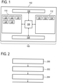
- Fig. 1 shows an example of a medical imaging system 100.
- the medical imaging system 100 is shown as comprising a computer system 102.
- the computer system 102 may for instance have a hardware 104 or a network interface.
- the computer system is further shown as containing a processor 106 that is connected to the hardware or network interface 104, a user interface 108, computer storage 110, and computer memory 112.
- the computer storage 110 is shown as containing preliminary magnetic resonance data 120.
- the computer storage 110 is further shown as containing a preliminary magnetic resonance image that was reconstructed from the preliminary magnetic resonance data 120.
- the computer storage 110 is further shown as containing a preliminary segmentation 124 of the preliminary magnetic resonance image 122.
- the presence of the preliminary magnetic resonance data 120 and the preliminary magnetic resonance image 122 is optional.
- the computer system 102 could have received the preliminary segmentation 124 already performed.
- the computer system 102 could reconstruct the preliminary magnetic resonance image 122 from the preliminary magnetic resonance data 120 and then determine the segmentation 124 by segmenting the preliminary magnetic resonance image 122.
- the computer storage 110 is further shown as containing QSM magnetic resonance data 120.
- the processor 106 could control a magnetic resonance imaging system to acquire the QSM magnetic resonance data 120.
- the QSM magnetic resonance data 120 may be received over a network connection or other storage device.
- the computer storage 110 is further shown as containing a first QSM image 124 that was reconstructed from the QSM magnetic resonance data 120.
- the computer storage 110 is further shown as containing a first segmentation 126 of the first QSM image 124.
- the computer storage 110 is further shown as containing a second QSM image 128 that was reconstructed using the QSM magnetic resonance data 120 and the first segmentation 126.
- the computer memory 112 is shown as containing machine-executable instructions 130 that enable the processor 106 to perform such things as control the medical imaging system 100 and also to perform various numerical and image processing techniques as is detailed in Fig. 2 , Fig. 3 , Fig. 5 , and Fig. 6 .
- the computer memory 112 is further shown as containing an optional survey scan image segmentation algorithm 132 that may be optionally used for example for segmenting the preliminary magnetic resonance image 122.
- the computer storage 112 is further shown as containing a QSM image segmentation algorithm 134 which for example may be used for segmenting the first QSM image 124 and/or the second QSM image 128.
- the survey scan image segmentation algorithm 132 and the QSM image segmentation algorithm 134 may be in some cases essentially the same algorithm that is trained or adjusted differently depending upon the various features which are visible in the preliminary magnetic resonance image 122 or the QSM images 124, 128. In other cases the segmentation algorithm 132 and the algorithm 134 are different.
- Fig. 2 shows a flowchart which illustrates a method of using the medical imaging system 100 of Fig. 1 .
- the preliminary segmentation 124 is received.
- the preliminary segmentation 124 is received from an external device and has already been performed.
- the processor 106 may control a magnetic resonance imaging system to acquire the preliminary magnetic resonance data 120 then to reconstruct the preliminary magnetic resonance image 122 and then finally to segment this image 122 to calculate the preliminary segmentation 124.
- a first QSM image 124 is reconstructed for the region of interest from the QSM magnetic resonance data 122.
- a first segmentation 126 is calculated by segmenting the first QSM image 124 using a QSM image segmentation algorithm 134. The first segmentation comprises first segmentation edges.
- a second QSM image 128 is reconstructed for the region of interest from the QSM magnetic resonance data.
- the reconstruction of the second QSM image is at least partially performed using the regularization function.
- the regularization function is dependent upon the first segmentation edges.
- Fig. 3 shows a further flowchart which illustrates a further method of operating the medical imaging system 100 of Fig. 1 .
- the method in Fig. 3 for the first four steps 200, 202, 204 and 206 are identical with the method illustrated in Fig. 2 .
- the method then proceeds to the question box 300.
- the question box 300 may take different forms in different examples. In one example the calculation of the second QSM image is performed iteratively a fixed number of times. In this first example the question may be has the number of iterations been performed. If the answer is yes the method proceeds to box 312 and the method ends. If the answer is no the method proceeds to box 310 and the first segmentation is recalculated by segmenting the existing second QSM image.
- the method then proceeds back to step 206 and the second QSM image is then reconstructed using the first segmentation 126 that was just recalculated.
- the method may then repeat until the number of iterations is reached.
- the question box 300 may represent comparing the present second QSM image to a second QSM image that was calculated in a previous iteration. This for example may be used to see if the second QSM image has converged.
- Various statistical measures such as preparing pixels or voxels on a voxel-by-voxel basis may be used to evaluate if the second QSM image 128 has converged to a solution.
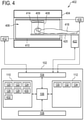
- Fig. 4 shows a further example of a medical imaging system 400.
- the medical imaging system 400 further comprises a magnetic resonance imaging system 402.
- the medical imaging system 400 also comprises a computer system 102 such as illustrated in Fig. 1 .
- the processor 106 is used to control the magnetic resonance imaging system 402.
- the medical imaging system 400 comprises a magnetic resonance imaging system 402 and a computer system 102 with a processor 106 that is equivalent to the medical imaging system 100 shown in Fig. 1 .
- the magnetic resonance imaging system 402 comprises a magnet 404.
- the magnet 404 is a superconducting cylindrical type magnet 404 with a bore 406 through it.
- the use of different types of magnets is also possible; for instance it is also possible to use both a split cylindrical magnet and a so called open magnet.
- a split cylindrical magnet is similar to a standard cylindrical magnet, except that the cryostat has been split into two sections to allow access to the iso-plane of the magnet, such magnets may for instance be used in conjunction with charged particle beam therapy.
- An open magnet has two magnet sections, one above the other with a space in-between that is large enough to receive a subject: the arrangement of the two sections area similar to that of a Helmholtz coil. Open magnets are popular, because the subject is less confined. Inside the cryostat of the cylindrical magnet there is a collection of superconducting coils. Within the bore 406 of the cylindrical magnet 404 there is an imaging zone 408 where the magnetic field is strong and uniform enough to perform magnetic resonance imaging.
- the magnetic field gradient coils 410 are connected to a magnetic field gradient coil power supply 412.
- the magnetic field gradient coils 410 are intended to be representative.
- magnetic field gradient coils 410 contain three separate sets of coils for spatially encoding in three orthogonal spatial directions.
- a magnetic field gradient power supply supplies current to the magnetic field gradient coils. The current supplied to the magnetic field gradient coils 410 is controlled as a function of time and may be ramped or pulsed.
- a radio-frequency coil 414 Adjacent to the imaging zone 408 is a radio-frequency coil 414 for manipulating the orientations of magnetic spins within the imaging zone 408 and for receiving radio transmissions from spins also within the imaging zone 408.
- a region of interest 409 within the imaging zone 408 is shown.
- the radio frequency antenna may contain multiple coil elements.
- the radio frequency antenna may also be referred to as a channel or antenna.
- the radio-frequency coil 414 is connected to a radio frequency transceiver 416.
- the radio-frequency coil 414 and radio frequency transceiver 416 may be replaced by separate transmit and receive coils and a separate transmitter and receiver. It is understood that the radio-frequency coil 414 and the radio frequency transceiver 416 are representative.
- the radio-frequency coil 414 is intended to also represent a dedicated transmit antenna and a dedicated receive antenna. Likewise the transceiver 416 may also represent a separate transmitter and receiver. The radio-frequency coil 414 may also have multiple receive/transmit elements and the radio frequency transceiver 416 may have multiple receive/transmit channels.
- the subject support 420 is attached to an optional actuator 422 that is able to move the subject support and the subject 418 through the imaging zone 408. In this way a larger portion of the subject 418 or the entire subject 418 can be imaged.
- the transceiver 416, the magnetic field gradient coil power supply 412 and the actuator 422 are all see as being connected to a hardware interface 104 of computer system 102.
- the computer system 102 is equivalent to the computer system 102 shown in Fig. 1 .
- the computer storage 110 is shown as containing QSM pulse sequence commands 430. These commands enable the processor 106 to control the magnetic resonance imaging system 402 to acquire the QSM magnetic resonance data 220 for the region of interest 409.
- the computer storage 110 is also further shown as containing optional survey scan pulse sequence commands 432.
- the processor 106 may use the survey scan pulse sequence commands 432 to control the magnetic resonance imaging system 402 to acquire the preliminary magnetic resonance data 120 from a region that at least includes the region of interest 409.
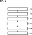
- Fig. 5 shows a flowchart which illustrates a method of controlling the medical imaging system 400 of Fig. 4 .
- the preliminary magnetic resonance image 122 is a QSM image that is calculated from the QSM magnetic resonance data 120.
- the QSM magnetic resonance image is calculated without using segmentation edges to control the operation of the regularization function.
- the processor 106 controls the magnetic resonance imaging system 402 with the QSM pulse sequence commands 430 to acquire the QSM magnetic resonance data 120.
- the preliminary magnetic resonance data 120 may not be present in the system.
- step 502 the preliminary magnetic resonance image 122 is reconstructed or calculated from the preliminary magnetic resonance data 120. In this case it is also a QSM magnetic resonance image.
- the method then continues to step 200 and is equivalent to the method shown in Fig. 2 .
- the receiving of the preliminary segmentation comprises calculating the preliminary segmentation by segmenting the first QSM image using the QSM image segmenting algorithm.
- Fig. 6 shows a flowchart which illustrates an alternate method of controlling the medical imaging system 400.
- the preliminary magnetic resonance image is a survey magnetic resonance image which is acquired by the magnetic resonance imaging system 402.
- the preliminary magnetic resonance data 120 which may also be referred to as the survey magnetic resonance imaging data, may be acquired by controlling the magnetic resonance imaging system with survey scan pulse sequence commands 432.
- the preliminary magnetic resonance image 122 which is also referred to as the survey magnetic resonance image in this example, is reconstructed from the preliminary magnetic resonance data 120.
- step 500 the QSM magnetic resonance data 120 is acquired by controlling the magnetic resonance imaging system 402 with QSM pulse sequence commands 430.
- the method then proceeds to steps 200, 202, 204 and 206 as are illustrated in Fig. 2 .
- step 200 which is to receive the preliminary segmentation, comprises calculating the preliminary segmentation by segmenting the preliminary magnetic resonance image 122.
- Figs. 5 and 6 may be modified in several ways.
- the iterative method illustrated in Fig. 3 may also be combined with Figs. 5 and 6 .
- Fig. 5 may also be further modified.
- Fig. 5 there are three QSM reconstructions of the QSM magnetic resonance data 120.
- the method shown in Fig. 5 may be stopped after step 202.
- Quantitative Susceptibility Mapping is an emerging technique to reconstruct the tissue magnetic susceptibility from single- or multi-echo gradient echo MRI.
- One of the central challenges in QSM reconstruction is the inherent loss of information in the mapping from the tissue susceptibility to the resulting field perturbation, making QSM reconstruction an ill-posed inverse problem.
- Many approaches have been proposed to improve the conditioning of the problem by regularization, the most successful ones employing a gradient-based regularization in combination with additional information about the geometry of the tissue distribution derived from magnitude images.
- segmentation software packages work on T1-weighted images with magnetization preparation using an inversion pulse. These images show poor contrast for several prominent structures in the brain, such as putamen, globus pallidus, red nucleus, substantia nigra and dentate nucleus, which bears the risk of errors in the segmentation. These errors will then propagate in the reconstructed susceptibility if segmented and actual tissue boundaries do not overlap.
- This invention proposes to iteratively update the segmentation to include new information about tissue geometry.
- a first susceptibility map is reconstructed guided by gradient-derived magnitude edges and/or edges derived from the initial segmentation.
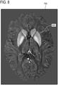
- the resulting susceptibility map is used to refine the segmentation to improve the initial segmentation, see Fig. 7 below, to better describe tissue boundaries in the susceptibility, see Fig. 8 below.
- Figs. 7 and 8 show an example of a QSM image 700.
- the QSM image 700 is shown with eight segmentations.
- the segmentations shown in Fig. 7 are from an initial segmentation for example from a survey image. Upon examining Fig. 7 it can be seen that the segmentations do not line up with all of the structures shown in the QSM image 700 very well.
- Fig. 8 the segmentation has been performed on the QSM image 700 using an image segmentation module that has been modified to find the structures in the QSM image 700. It can be seen that the segmentation is much more accurate and better fits the anatomy of the subject shown in image 700.
- the segmentations shown in Fig. 8 may be an example of a first segmentation of the QSM image.
- the segmentations 800 may be used for further reconstruction of the QSM image again.
- Some example methods may include one or more of the following steps:
- Another alternative would be to skip step 3 above and to postpone segmentation until the first approximate susceptibility solution is available for segmentation.
- a computer program may be stored/distributed on a suitable medium, such as an optical storage medium or a solid-state medium supplied together with or as part of other hardware, but may also be distributed in other forms, such as via the Internet or other wired or wireless telecommunication systems. Any reference signs in the claims should not be construed as limiting the scope.
Landscapes
- Physics & Mathematics (AREA)
- Engineering & Computer Science (AREA)
- General Physics & Mathematics (AREA)
- Condensed Matter Physics & Semiconductors (AREA)
- Radiology & Medical Imaging (AREA)
- Nuclear Medicine, Radiotherapy & Molecular Imaging (AREA)
- Signal Processing (AREA)
- General Health & Medical Sciences (AREA)
- High Energy & Nuclear Physics (AREA)
- Health & Medical Sciences (AREA)
- Artificial Intelligence (AREA)
- Computer Vision & Pattern Recognition (AREA)
- Magnetic Resonance Imaging Apparatus (AREA)
Claims (8)
- Ein medizinisches Bildgebungssystem (100, 400), das Folgendes umfasst:- einen Speicher (112) zum Speichern von maschinell ausführbaren Anweisungen;- einen Prozessor (106) zum Steuern des medizinischen Bildgebungssystems, wobei das Ausführen der maschinell ausführbaren Anweisungen den Prozessor zu folgenden Schritten veranlasst:• Rekonstruieren (502) eines vorläufigen Bilds der zu untersuchenden Region einer Person aus quantitativen Suszeptibilitätskartierungs-QSM-Magnetresonanz-Bildgebungsdaten (120),
Berechnen einer vorläufigen Segmentierung durch Segmentieren des vorläufigen Bilds unter Verwendung eines QSM-Bildsegmentierungsalgorithmus, wobei die vorläufige Segmentierung vorläufige Segmentierungskanten umfasst;• Rekonstruieren (202) eines ersten QSM-Bilds (124) der zu untersuchenden Region aus den QSM-Magnetresonanz-Bildgebungsdaten (120),
wobei das Rekonstruieren des QSM-Bilds zumindest teilweise unter Verwendung einer Regularisierungsfunktion durchgeführt wird, wobei die Regularisierungsfunktion von den vorläufigen Segmentierungskanten beim Rekonstruieren des ersten QSM-Bilds abhängig ist;• Berechnen (204) einer ersten Segmentierung (126) durch Segmentieren des ersten QSM-Bilds unter Verwendung des QSM-Bildsegmentierungsalgorithmus (134), wobei die erste Segmentierung erste Segmentierungskanten umfasst; und• Rekonstruieren (206) eines zweiten QSM-Bilds (128) der zu untersuchenden Region aus den QSM-Magnetresonanz-Bildgebungsdaten (120),
wobei das Rekonstruieren des zweiten QSM-Bilds zumindest teilweise unter Verwendung einer Regularisierungsfunktion durchgeführt wird, wobei die Regularisierungsfunktion von den ersten Segmentierungskanten abhängig ist, und• wobei das Ausführen der maschinell ausführbaren Anweisungen den Prozessor zudem zu folgenden sich wiederholenden Schritten veranlasst:• Neuberechnen (310) der ersten Segmentierung durch Segmentieren des zweiten QSM-Bilds unter Verwendung des QSM-Bildsegmentierungsalgorithmus; und• Rekonstruieren (206) des zweiten QSM-Bilds der zu untersuchenden Region aus den QSM-Magnetresonanz-Bildgebungsdaten. - Das medizinische Bildgebungssystem gemäß Anspruch 1, wobei das sich wiederholende Rekonstruieren des zweiten QSM-Bilds für eine vorab festgelegte Anzahl von Wiederholungen durchgeführt wird.
- Das medizinische Bildgebungssystem gemäß Anspruch 1, wobei das sich wiederholende Rekonstruieren des zweiten QSM-Bilds durchgeführt wird, bis eine Konvergenzmetrik innerhalb eines vorab festgelegten Bereichs liegt.
- Das medizinische Bildgebungssystem gemäß einem der vorherigen Ansprüche,wobei das medizinische Bildgebungssystem zudem ein Magnetresonanztomographie-System (402) umfasst,wobei im Speicher zudem QSM-Impulssequenzbefehle (430) gespeichert werden, wobei die QSM-Impulssequenzbefehle das Magnetresonanztomographie-System dazu veranlassen, die QSM-Magnetresonanztomographie-Daten gemäß einem quantitativen Magnetresonanz-Suszeptibilitätskartierungsprotokoll zu erfassen (500), wobei das Ausführen der maschinell ausführbaren Befehle den Prozessor dazu veranlasst, das Magnetresonanztomographie-System zu steuern, um die QSM-Magnetresonanztomographie-Daten unter Verwendung der QSM-Impulssequenzbefehle zu erfassen.
- Das medizinische Bildgebungssystem gemäß einem der vorherigen Ansprüche, wobei das Rekonstruieren des ersten QSM-Bilds und/oder des zweiten QSM-Bilds das Auflösen der folgenden Gleichung umfasst:

- Das medizinische Bildgebungssystem gemäß einem der vorherigen Ansprüche, wobei der QSM-Bildsegmentierungsalgorithmus unter Verwendung von QSM-Bildern angelernt und/oder konfiguriert wird.
- Eine Methode zum Betreiben eines medizinischen Bildgebungssystems (100, 400) mit einem Speicher zum Speichern von maschinell ausführbaren Anweisungen sowie einem Prozessor zum Steuern des medizinischen Bildgebungssystems, wobei
das Ausführen der maschinell ausführbaren Anweisungen den Prozessor zu folgenden Schritten veranlasst:• Rekonstruieren (502) eines vorläufigen Bilds der zu untersuchenden Region einer Person aus quantitativen Suszeptibilitätskartierungs-QSM-Magnetresonanz-Bildgebungsdaten (120),
Berechnen einer vorläufigen Segmentierung durch Segmentieren des vorläufigen Bilds unter Verwendung eines QSM-Bildsegmentierungsalgorithmus, wobei die vorläufige Segmentierung vorläufige Segmentierungskanten umfasst;• Rekonstruieren (202) eines ersten QSM-Bilds (124) der zu untersuchenden Region aus den QSM-Magnetresonanz-Bildgebungsdaten (120),
wobei das Rekonstruieren des QSM-Bilds zumindest teilweise unter Verwendung einer Regularisierungsfunktion durchgeführt wird, wobei die Regularisierungsfunktion von den vorläufigen Segmentierungskanten beim Rekonstruieren des ersten QSM-Bilds abhängig ist;• Berechnen (204) einer ersten Segmentierung (126) durch Segmentieren des ersten QSM-Bilds unter Verwendung des QSM-Bildsegmentierungsalgorithmus (134), wobei die erste Segmentierung erste Segmentierungskanten umfasst; und• Rekonstruieren (206) eines zweiten QSM-Bilds (128) der zu untersuchenden Region aus den QSM-Magnetresonanz-Bildgebungsdaten (120),
wobei das Rekonstruieren des zweiten QSM-Bilds zumindest teilweise unter Verwendung einer Regularisierungsfunktion durchgeführt wird, wobei die Regularisierungsfunktion von den ersten Segmentierungskanten abhängig ist, und• wobei das Ausführen der maschinell ausführbaren Anweisungen den Prozessor zudem zu folgenden sich wiederholenden Schritten veranlasst:• Neuberechnen (310) der ersten Segmentierung durch Segmentieren des zweiten QSM-Bilds unter Verwendung des QSM-Bildsegmentierungsalgorithmus; und• Rekonstruieren (206) des zweiten QSM-Bilds der zu untersuchenden Region aus den QSM-Magnetresonanz-Bildgebungsdaten. - Ein Computerprogrammprodukt mit maschinell ausführbaren Anweisungen (130), die von einem Prozessor (106) ausgeführt werden, der ein medizinisches Bildgebungssystem (100, 400) steuert,
wobei das Ausführen der maschinell ausführbaren Anweisungen den Prozessor zu folgenden Schritten veranlasst:• Rekonstruieren (502) eines vorläufigen Bilds der zu untersuchenden Region einer Person aus quantitativen Suszeptibilitätskartierungs-QSM-Magnetresonanz-Bildgebungsdaten (120),
Berechnen einer vorläufigen Segmentierung durch Segmentieren des vorläufigen Bilds unter Verwendung eines QSM-Bildsegmentierungsalgorithmus, wobei die vorläufige Segmentierung vorläufige Segmentierungskanten umfasst;• Rekonstruieren (202) eines ersten QSM-Bilds (124) der zu untersuchenden Region aus den QSM-Magnetresonanz-Bildgebungsdaten (120),
wobei das Rekonstruieren des QSM-Bilds zumindest teilweise unter Verwendung einer Regularisierungsfunktion durchgeführt wird, wobei die Regularisierungsfunktion von den vorläufigen Segmentierungskanten beim Rekonstruieren des ersten QSM-Bilds abhängig ist;• Berechnen (204) einer ersten Segmentierung (126) durch Segmentieren des ersten QSM-Bilds unter Verwendung des QSM-Bildsegmentierungsalgorithmus (134), wobei die erste Segmentierung erste Segmentierungskanten umfasst; und• Rekonstruieren (206) eines zweiten QSM-Bilds (128) der zu untersuchenden Region aus den QSM-Magnetresonanz-Bildgebungsdaten (120),
wobei das Rekonstruieren des zweiten QSM-Bilds zumindest teilweise unter Verwendung einer Regularisierungsfunktion durchgeführt wird, wobei die Regularisierungsfunktion von den ersten Segmentierungskanten abhängig ist, und• wobei das Ausführen der maschinell ausführbaren Anweisungen den Prozessor zudem zu folgenden sich wiederholenden Schritten veranlasst:• Neuberechnen (310) der ersten Segmentierung durch Segmentieren des zweiten QSM-Bilds unter Verwendung des QSM-Bildsegmentierungsalgorithmus; und• Rekonstruieren (206) des zweiten QSM-Bilds der zu untersuchenden Region aus den QSM-Magnetresonanz-Bildgebungsdaten.
Applications Claiming Priority (2)
| Application Number | Priority Date | Filing Date | Title |
|---|---|---|---|
| EP15200768 | 2015-12-17 | ||
| PCT/EP2016/080546 WO2017102611A1 (en) | 2015-12-17 | 2016-12-12 | Segmentation of quantitative susceptibility mapping magnetic resonance images |
Publications (2)
| Publication Number | Publication Date |
|---|---|
| EP3391069A1 EP3391069A1 (de) | 2018-10-24 |
| EP3391069B1 true EP3391069B1 (de) | 2022-02-09 |
Family
ID=55066348
Family Applications (1)
| Application Number | Title | Priority Date | Filing Date |
|---|---|---|---|
| EP16806191.9A Not-in-force EP3391069B1 (de) | 2015-12-17 | 2016-12-12 | Segmentierung von mr-bildern der quantitativen suszeptibilität |
Country Status (5)
| Country | Link |
|---|---|
| US (1) | US10761170B2 (de) |
| EP (1) | EP3391069B1 (de) |
| JP (1) | JP6907209B2 (de) |
| CN (1) | CN108431624B (de) |
| WO (1) | WO2017102611A1 (de) |
Families Citing this family (7)
| Publication number | Priority date | Publication date | Assignee | Title |
|---|---|---|---|---|
| US11448717B2 (en) * | 2017-12-29 | 2022-09-20 | Siemens Healthcare Gmbh | Method and deep quantitative susceptibility mapping (QSM) |
| CN108665465B (zh) * | 2018-05-14 | 2019-07-19 | 东软医疗系统股份有限公司 | 分割缺血半暗带的方法、装置、存储介质及设备 |
| CN111090068B (zh) * | 2018-10-23 | 2021-03-23 | 中国科学院深圳先进技术研究院 | 磁共振正对比成像方法及装置 |
| CN110074786B (zh) * | 2019-04-30 | 2022-12-06 | 上海东软医疗科技有限公司 | 核磁共振匀场方法、装置、计算设备及核磁共振成像系统 |
| CN110992435B (zh) * | 2019-11-06 | 2023-10-20 | 上海东软医疗科技有限公司 | 图像重建方法及设备、成像数据的处理方法及装置 |
| EP3865892A1 (de) * | 2020-02-17 | 2021-08-18 | Koninklijke Philips N.V. | Iterative rekonstruktion von gradientenbildern durch echo-magnetische resonanz |
| CN112037304B (zh) * | 2020-09-02 | 2023-12-08 | 上海大学 | 基于swi相位图像的两阶段的边缘增强qsm重建方法 |
Family Cites Families (23)
| Publication number | Priority date | Publication date | Assignee | Title |
|---|---|---|---|---|
| EP2145198A1 (de) * | 2007-04-30 | 2010-01-20 | Koninklijke Philips Electronics N.V. | Mr-bildgebung mit positivem suszeptibilitätskontrast |
| CN102077108B (zh) * | 2008-04-28 | 2015-02-25 | 康奈尔大学 | 分子mri中的磁敏度精确量化 |
| US20130102879A1 (en) * | 2010-04-14 | 2013-04-25 | Universitaetsklinikum Freiburg | Method For Correcting Susceptibility-Induced Image Artifacts In MRI After Prospective Motion Correction |
| US10380735B2 (en) | 2010-04-16 | 2019-08-13 | Koninklijke Philips N.V. | Image data segmentation |
| US8422756B2 (en) | 2010-04-27 | 2013-04-16 | Magnetic Resonance Innovations, Inc. | Method of generating nuclear magnetic resonance images using susceptibility weighted imaging and susceptibility mapping (SWIM) |
| US9448289B2 (en) * | 2010-11-23 | 2016-09-20 | Cornell University | Background field removal method for MRI using projection onto dipole fields |
| WO2012174177A2 (en) * | 2011-06-15 | 2012-12-20 | Chunlei Liu | Systems and methods for imaging and quantifying tissue magnetism with magnetic resonance imaging |
| JP5843876B2 (ja) * | 2011-10-12 | 2016-01-13 | 株式会社日立製作所 | 磁気共鳴イメージング装置および磁化率強調画像生成方法 |
| US9213076B2 (en) * | 2012-02-27 | 2015-12-15 | Medimagemetric LLC | System, process and computer-accessible medium for providing quantitative susceptibility mapping |
| CN104541178B (zh) * | 2012-07-18 | 2017-11-07 | 皇家飞利浦有限公司 | 基于根据mDIXON调查的自动规划的高效心脏MR工作流 |
| WO2014057716A1 (ja) * | 2012-10-10 | 2014-04-17 | 株式会社日立製作所 | 磁気共鳴イメージング装置 |
| US9766316B2 (en) | 2012-11-16 | 2017-09-19 | Hitachi, Ltd. | Magnetic resonance imaging device and quantitative susceptibility mapping method |
| KR101359134B1 (ko) * | 2012-12-28 | 2014-02-06 | 연세대학교 산학협력단 | 도전율 및 자화율 복원 장치 및 방법과 이에 관한 기록매체 |
| US10534060B2 (en) * | 2013-06-10 | 2020-01-14 | Toshiba Medical Systems Corporation | Parallel MRI with spatially misregistered signal |
| US9664761B2 (en) * | 2013-06-26 | 2017-05-30 | Medimagemetric LLC | Joint estimation of chemical shift and quantitative susceptibility map using MRI signal |
| JP6085545B2 (ja) * | 2013-09-26 | 2017-02-22 | 株式会社日立製作所 | 磁気共鳴イメージング装置、画像処理装置および磁化率画像算出方法 |
| US9612300B2 (en) * | 2013-11-25 | 2017-04-04 | Wisconsin Alumni Research Foundation | System and method for object-based initialization of magnetic field inhomogeneity in magnetic resonance imaging |
| US9542763B2 (en) * | 2014-04-25 | 2017-01-10 | The General Hospital Corporation | Systems and methods for fast reconstruction for quantitative susceptibility mapping using magnetic resonance imaging |
| CN104267361A (zh) * | 2014-10-13 | 2015-01-07 | 厦门大学 | 基于结构特征的自适应定量磁化率分布图复合重建的方法 |
| WO2016076076A1 (ja) * | 2014-11-11 | 2016-05-19 | 株式会社日立メディコ | 磁気共鳴イメージング装置および定量的磁化率マッピング方法 |
| US10746822B2 (en) * | 2015-06-24 | 2020-08-18 | The Medical College Of Wisconsin, Inc. | System and method for localized processing of quantitative susceptibility maps in magnetic resonance imaging |
| JP6618754B2 (ja) * | 2015-10-06 | 2019-12-11 | キヤノンメディカルシステムズ株式会社 | 磁気共鳴イメージング装置、画像処理装置、及び画像処理方法 |
| JP6702691B2 (ja) * | 2015-10-30 | 2020-06-03 | キヤノンメディカルシステムズ株式会社 | 磁気共鳴イメージング及び医用画像処理装置 |
-
2016
- 2016-12-12 CN CN201680074046.5A patent/CN108431624B/zh not_active Expired - Fee Related
- 2016-12-12 WO PCT/EP2016/080546 patent/WO2017102611A1/en not_active Ceased
- 2016-12-12 JP JP2018530842A patent/JP6907209B2/ja not_active Expired - Fee Related
- 2016-12-12 EP EP16806191.9A patent/EP3391069B1/de not_active Not-in-force
- 2016-12-12 US US16/062,146 patent/US10761170B2/en not_active Expired - Fee Related
Also Published As
| Publication number | Publication date |
|---|---|
| JP2019504664A (ja) | 2019-02-21 |
| CN108431624A (zh) | 2018-08-21 |
| WO2017102611A1 (en) | 2017-06-22 |
| US20180372826A1 (en) | 2018-12-27 |
| US10761170B2 (en) | 2020-09-01 |
| EP3391069A1 (de) | 2018-10-24 |
| JP6907209B2 (ja) | 2021-07-21 |
| CN108431624B (zh) | 2021-05-25 |
Similar Documents
| Publication | Publication Date | Title |
|---|---|---|
| EP3391069B1 (de) | Segmentierung von mr-bildern der quantitativen suszeptibilität | |
| US10698062B2 (en) | Diffusion MRI method for generating a synthetic diffusion image at a high B-value | |
| CN110476075B (zh) | 针对解剖区域的磁共振指纹识别词典的选择 | |
| US11092659B2 (en) | Sub voxel resolution magnetic resonance fingerprinting imaging | |
| US10591562B2 (en) | Bone MRI using B0 inhomogeneity map and a subject magnetic susceptibility map | |
| CN105659103A (zh) | 狄克逊磁共振成像 | |
| US11199601B2 (en) | Quantitative measurement of relaxation times in magnetic resonance imaging | |
| EP3542176B1 (de) | Intensitätskorrigierte magnetresonanzbilder | |
| US20160146918A1 (en) | Corrected magnetic resonance imaging using coil sensitivities | |
| EP3931587B1 (de) | Berechnung eines b0-bildes mithilfe mehrerer diffusionsgewichteter mrt-bilder | |
| US10295633B2 (en) | Dixon magnetic resonance imaging using prior knowledge | |
| EP4220212A1 (de) | Simulierte computertomografiebildgebung | |
| EP4653904A1 (de) | Entfernung von freiinduktionszerfallsartefakten in turbo-spin-echo-mrt-bilder | |
| EP4306980A1 (de) | Bestimmung der b0-inhomogenität in der magnetresonanztomographie | |
| US20250155535A1 (en) | Simulated computer tomographic imaging | |
| JP7542633B2 (ja) | 勾配エコー磁気共鳴画像の反復的再構成 | |
| EP4657105A1 (de) | Turbofeld-echo-magnetresonanzbildgebung mit anfangsspinecho-vorbereitungsimpuls | |
| EP4074253A1 (de) | Segmentierung unter verwendung mehrerer bildkontraste | |
| WO2023148039A1 (en) | Simulated computer tomographic imaging | |
| EP3543724A1 (de) | (3-n)-dimensionale bestimmung der elektrischen leitfähigkeit | |
| EP4555335A1 (de) | Bestimmung der bo-inhomogenität in der magnetresonanzbildgebung |
Legal Events
| Date | Code | Title | Description |
|---|---|---|---|
| STAA | Information on the status of an ep patent application or granted ep patent |
Free format text: STATUS: UNKNOWN |
|
| STAA | Information on the status of an ep patent application or granted ep patent |
Free format text: STATUS: THE INTERNATIONAL PUBLICATION HAS BEEN MADE |
|
| PUAI | Public reference made under article 153(3) epc to a published international application that has entered the european phase |
Free format text: ORIGINAL CODE: 0009012 |
|
| STAA | Information on the status of an ep patent application or granted ep patent |
Free format text: STATUS: REQUEST FOR EXAMINATION WAS MADE |
|
| 17P | Request for examination filed |
Effective date: 20180717 |
|
| AK | Designated contracting states |
Kind code of ref document: A1 Designated state(s): AL AT BE BG CH CY CZ DE DK EE ES FI FR GB GR HR HU IE IS IT LI LT LU LV MC MK MT NL NO PL PT RO RS SE SI SK SM TR |
|
| AX | Request for extension of the european patent |
Extension state: BA ME |
|
| DAV | Request for validation of the european patent (deleted) | ||
| DAX | Request for extension of the european patent (deleted) | ||
| RAP1 | Party data changed (applicant data changed or rights of an application transferred) |
Owner name: KONINKLIJKE PHILIPS N.V. |
|
| GRAP | Despatch of communication of intention to grant a patent |
Free format text: ORIGINAL CODE: EPIDOSNIGR1 |
|
| STAA | Information on the status of an ep patent application or granted ep patent |
Free format text: STATUS: GRANT OF PATENT IS INTENDED |
|
| INTG | Intention to grant announced |
Effective date: 20210727 |
|
| GRAS | Grant fee paid |
Free format text: ORIGINAL CODE: EPIDOSNIGR3 |
|
| GRAA | (expected) grant |
Free format text: ORIGINAL CODE: 0009210 |
|
| STAA | Information on the status of an ep patent application or granted ep patent |
Free format text: STATUS: THE PATENT HAS BEEN GRANTED |
|
| AK | Designated contracting states |
Kind code of ref document: B1 Designated state(s): AL AT BE BG CH CY CZ DE DK EE ES FI FR GB GR HR HU IE IS IT LI LT LU LV MC MK MT NL NO PL PT RO RS SE SI SK SM TR |
|
| REG | Reference to a national code |
Ref country code: GB Ref legal event code: FG4D |
|
| REG | Reference to a national code |
Ref country code: CH Ref legal event code: EP Ref country code: AT Ref legal event code: REF Ref document number: 1467840 Country of ref document: AT Kind code of ref document: T Effective date: 20220215 |
|
| REG | Reference to a national code |
Ref country code: DE Ref legal event code: R096 Ref document number: 602016068996 Country of ref document: DE |
|
| REG | Reference to a national code |
Ref country code: IE Ref legal event code: FG4D |
|
| REG | Reference to a national code |
Ref country code: DE Ref legal event code: R084 Ref document number: 602016068996 Country of ref document: DE |
|
| REG | Reference to a national code |
Ref country code: LT Ref legal event code: MG9D |
|
| REG | Reference to a national code |
Ref country code: NL Ref legal event code: MP Effective date: 20220209 |
|
| REG | Reference to a national code |
Ref country code: GB Ref legal event code: 746 Effective date: 20220527 |
|
| REG | Reference to a national code |
Ref country code: AT Ref legal event code: MK05 Ref document number: 1467840 Country of ref document: AT Kind code of ref document: T Effective date: 20220209 |
|
| PG25 | Lapsed in a contracting state [announced via postgrant information from national office to epo] |
Ref country code: SE Free format text: LAPSE BECAUSE OF FAILURE TO SUBMIT A TRANSLATION OF THE DESCRIPTION OR TO PAY THE FEE WITHIN THE PRESCRIBED TIME-LIMIT Effective date: 20220209 Ref country code: RS Free format text: LAPSE BECAUSE OF FAILURE TO SUBMIT A TRANSLATION OF THE DESCRIPTION OR TO PAY THE FEE WITHIN THE PRESCRIBED TIME-LIMIT Effective date: 20220209 Ref country code: PT Free format text: LAPSE BECAUSE OF FAILURE TO SUBMIT A TRANSLATION OF THE DESCRIPTION OR TO PAY THE FEE WITHIN THE PRESCRIBED TIME-LIMIT Effective date: 20220609 Ref country code: NO Free format text: LAPSE BECAUSE OF FAILURE TO SUBMIT A TRANSLATION OF THE DESCRIPTION OR TO PAY THE FEE WITHIN THE PRESCRIBED TIME-LIMIT Effective date: 20220509 Ref country code: NL Free format text: LAPSE BECAUSE OF FAILURE TO SUBMIT A TRANSLATION OF THE DESCRIPTION OR TO PAY THE FEE WITHIN THE PRESCRIBED TIME-LIMIT Effective date: 20220209 Ref country code: LT Free format text: LAPSE BECAUSE OF FAILURE TO SUBMIT A TRANSLATION OF THE DESCRIPTION OR TO PAY THE FEE WITHIN THE PRESCRIBED TIME-LIMIT Effective date: 20220209 Ref country code: HR Free format text: LAPSE BECAUSE OF FAILURE TO SUBMIT A TRANSLATION OF THE DESCRIPTION OR TO PAY THE FEE WITHIN THE PRESCRIBED TIME-LIMIT Effective date: 20220209 Ref country code: ES Free format text: LAPSE BECAUSE OF FAILURE TO SUBMIT A TRANSLATION OF THE DESCRIPTION OR TO PAY THE FEE WITHIN THE PRESCRIBED TIME-LIMIT Effective date: 20220209 Ref country code: BG Free format text: LAPSE BECAUSE OF FAILURE TO SUBMIT A TRANSLATION OF THE DESCRIPTION OR TO PAY THE FEE WITHIN THE PRESCRIBED TIME-LIMIT Effective date: 20220509 |
|
| PG25 | Lapsed in a contracting state [announced via postgrant information from national office to epo] |
Ref country code: PL Free format text: LAPSE BECAUSE OF FAILURE TO SUBMIT A TRANSLATION OF THE DESCRIPTION OR TO PAY THE FEE WITHIN THE PRESCRIBED TIME-LIMIT Effective date: 20220209 Ref country code: LV Free format text: LAPSE BECAUSE OF FAILURE TO SUBMIT A TRANSLATION OF THE DESCRIPTION OR TO PAY THE FEE WITHIN THE PRESCRIBED TIME-LIMIT Effective date: 20220209 Ref country code: GR Free format text: LAPSE BECAUSE OF FAILURE TO SUBMIT A TRANSLATION OF THE DESCRIPTION OR TO PAY THE FEE WITHIN THE PRESCRIBED TIME-LIMIT Effective date: 20220510 Ref country code: FI Free format text: LAPSE BECAUSE OF FAILURE TO SUBMIT A TRANSLATION OF THE DESCRIPTION OR TO PAY THE FEE WITHIN THE PRESCRIBED TIME-LIMIT Effective date: 20220209 Ref country code: AT Free format text: LAPSE BECAUSE OF FAILURE TO SUBMIT A TRANSLATION OF THE DESCRIPTION OR TO PAY THE FEE WITHIN THE PRESCRIBED TIME-LIMIT Effective date: 20220209 |
|
| PG25 | Lapsed in a contracting state [announced via postgrant information from national office to epo] |
Ref country code: IS Free format text: LAPSE BECAUSE OF FAILURE TO SUBMIT A TRANSLATION OF THE DESCRIPTION OR TO PAY THE FEE WITHIN THE PRESCRIBED TIME-LIMIT Effective date: 20220609 |
|
| PG25 | Lapsed in a contracting state [announced via postgrant information from national office to epo] |
Ref country code: SM Free format text: LAPSE BECAUSE OF FAILURE TO SUBMIT A TRANSLATION OF THE DESCRIPTION OR TO PAY THE FEE WITHIN THE PRESCRIBED TIME-LIMIT Effective date: 20220209 Ref country code: SK Free format text: LAPSE BECAUSE OF FAILURE TO SUBMIT A TRANSLATION OF THE DESCRIPTION OR TO PAY THE FEE WITHIN THE PRESCRIBED TIME-LIMIT Effective date: 20220209 Ref country code: RO Free format text: LAPSE BECAUSE OF FAILURE TO SUBMIT A TRANSLATION OF THE DESCRIPTION OR TO PAY THE FEE WITHIN THE PRESCRIBED TIME-LIMIT Effective date: 20220209 Ref country code: EE Free format text: LAPSE BECAUSE OF FAILURE TO SUBMIT A TRANSLATION OF THE DESCRIPTION OR TO PAY THE FEE WITHIN THE PRESCRIBED TIME-LIMIT Effective date: 20220209 Ref country code: DK Free format text: LAPSE BECAUSE OF FAILURE TO SUBMIT A TRANSLATION OF THE DESCRIPTION OR TO PAY THE FEE WITHIN THE PRESCRIBED TIME-LIMIT Effective date: 20220209 Ref country code: CZ Free format text: LAPSE BECAUSE OF FAILURE TO SUBMIT A TRANSLATION OF THE DESCRIPTION OR TO PAY THE FEE WITHIN THE PRESCRIBED TIME-LIMIT Effective date: 20220209 |
|
| REG | Reference to a national code |
Ref country code: DE Ref legal event code: R097 Ref document number: 602016068996 Country of ref document: DE |
|
| PG25 | Lapsed in a contracting state [announced via postgrant information from national office to epo] |
Ref country code: AL Free format text: LAPSE BECAUSE OF FAILURE TO SUBMIT A TRANSLATION OF THE DESCRIPTION OR TO PAY THE FEE WITHIN THE PRESCRIBED TIME-LIMIT Effective date: 20220209 |
|
| PLBE | No opposition filed within time limit |
Free format text: ORIGINAL CODE: 0009261 |
|
| STAA | Information on the status of an ep patent application or granted ep patent |
Free format text: STATUS: NO OPPOSITION FILED WITHIN TIME LIMIT |
|
| 26N | No opposition filed |
Effective date: 20221110 |
|
| PGFP | Annual fee paid to national office [announced via postgrant information from national office to epo] |
Ref country code: DE Payment date: 20220628 Year of fee payment: 7 |
|
| PG25 | Lapsed in a contracting state [announced via postgrant information from national office to epo] |
Ref country code: SI Free format text: LAPSE BECAUSE OF FAILURE TO SUBMIT A TRANSLATION OF THE DESCRIPTION OR TO PAY THE FEE WITHIN THE PRESCRIBED TIME-LIMIT Effective date: 20220209 |
|
| PG25 | Lapsed in a contracting state [announced via postgrant information from national office to epo] |
Ref country code: IT Free format text: LAPSE BECAUSE OF FAILURE TO SUBMIT A TRANSLATION OF THE DESCRIPTION OR TO PAY THE FEE WITHIN THE PRESCRIBED TIME-LIMIT Effective date: 20220209 |
|
| REG | Reference to a national code |
Ref country code: CH Ref legal event code: PL |
|
| GBPC | Gb: european patent ceased through non-payment of renewal fee |
Effective date: 20221212 |
|
| REG | Reference to a national code |
Ref country code: BE Ref legal event code: MM Effective date: 20221231 |
|
| PG25 | Lapsed in a contracting state [announced via postgrant information from national office to epo] |
Ref country code: LU Free format text: LAPSE BECAUSE OF NON-PAYMENT OF DUE FEES Effective date: 20221212 |
|
| PG25 | Lapsed in a contracting state [announced via postgrant information from national office to epo] |
Ref country code: LI Free format text: LAPSE BECAUSE OF NON-PAYMENT OF DUE FEES Effective date: 20221231 Ref country code: IE Free format text: LAPSE BECAUSE OF NON-PAYMENT OF DUE FEES Effective date: 20221212 Ref country code: GB Free format text: LAPSE BECAUSE OF NON-PAYMENT OF DUE FEES Effective date: 20221212 Ref country code: CH Free format text: LAPSE BECAUSE OF NON-PAYMENT OF DUE FEES Effective date: 20221231 |
|
| PG25 | Lapsed in a contracting state [announced via postgrant information from national office to epo] |
Ref country code: FR Free format text: LAPSE BECAUSE OF NON-PAYMENT OF DUE FEES Effective date: 20221231 Ref country code: BE Free format text: LAPSE BECAUSE OF NON-PAYMENT OF DUE FEES Effective date: 20221231 |
|
| PG25 | Lapsed in a contracting state [announced via postgrant information from national office to epo] |
Ref country code: HU Free format text: LAPSE BECAUSE OF FAILURE TO SUBMIT A TRANSLATION OF THE DESCRIPTION OR TO PAY THE FEE WITHIN THE PRESCRIBED TIME-LIMIT; INVALID AB INITIO Effective date: 20161212 |
|
| PG25 | Lapsed in a contracting state [announced via postgrant information from national office to epo] |
Ref country code: CY Free format text: LAPSE BECAUSE OF FAILURE TO SUBMIT A TRANSLATION OF THE DESCRIPTION OR TO PAY THE FEE WITHIN THE PRESCRIBED TIME-LIMIT Effective date: 20220209 |
|
| PG25 | Lapsed in a contracting state [announced via postgrant information from national office to epo] |
Ref country code: MK Free format text: LAPSE BECAUSE OF FAILURE TO SUBMIT A TRANSLATION OF THE DESCRIPTION OR TO PAY THE FEE WITHIN THE PRESCRIBED TIME-LIMIT Effective date: 20220209 |
|
| PG25 | Lapsed in a contracting state [announced via postgrant information from national office to epo] |
Ref country code: MC Free format text: LAPSE BECAUSE OF FAILURE TO SUBMIT A TRANSLATION OF THE DESCRIPTION OR TO PAY THE FEE WITHIN THE PRESCRIBED TIME-LIMIT Effective date: 20220209 |
|
| PG25 | Lapsed in a contracting state [announced via postgrant information from national office to epo] |
Ref country code: MC Free format text: LAPSE BECAUSE OF FAILURE TO SUBMIT A TRANSLATION OF THE DESCRIPTION OR TO PAY THE FEE WITHIN THE PRESCRIBED TIME-LIMIT Effective date: 20220209 |
|
| REG | Reference to a national code |
Ref country code: DE Ref legal event code: R119 Ref document number: 602016068996 Country of ref document: DE |
|
| PG25 | Lapsed in a contracting state [announced via postgrant information from national office to epo] |
Ref country code: MT Free format text: LAPSE BECAUSE OF FAILURE TO SUBMIT A TRANSLATION OF THE DESCRIPTION OR TO PAY THE FEE WITHIN THE PRESCRIBED TIME-LIMIT Effective date: 20220209 |
|
| PG25 | Lapsed in a contracting state [announced via postgrant information from national office to epo] |
Ref country code: DE Free format text: LAPSE BECAUSE OF NON-PAYMENT OF DUE FEES Effective date: 20240702 |
|
| PG25 | Lapsed in a contracting state [announced via postgrant information from national office to epo] |
Ref country code: DE Free format text: LAPSE BECAUSE OF NON-PAYMENT OF DUE FEES Effective date: 20240702 |
|
| PG25 | Lapsed in a contracting state [announced via postgrant information from national office to epo] |
Ref country code: TR Free format text: LAPSE BECAUSE OF FAILURE TO SUBMIT A TRANSLATION OF THE DESCRIPTION OR TO PAY THE FEE WITHIN THE PRESCRIBED TIME-LIMIT Effective date: 20220209 |