EP3390234B1 - Formwerkzeug mit geteilter formschale - Google Patents
Formwerkzeug mit geteilter formschale Download PDFInfo
- Publication number
- EP3390234B1 EP3390234B1 EP16809395.3A EP16809395A EP3390234B1 EP 3390234 B1 EP3390234 B1 EP 3390234B1 EP 16809395 A EP16809395 A EP 16809395A EP 3390234 B1 EP3390234 B1 EP 3390234B1
- Authority
- EP
- European Patent Office
- Prior art keywords
- deep
- film
- segment
- packaging
- segments
- Prior art date
- Legal status (The legal status is an assumption and is not a legal conclusion. Google has not performed a legal analysis and makes no representation as to the accuracy of the status listed.)
- Active
Links
- 238000004806 packaging method and process Methods 0.000 claims description 60
- 238000007789 sealing Methods 0.000 claims description 16
- 238000003856 thermoforming Methods 0.000 claims description 10
- 238000001816 cooling Methods 0.000 claims description 2
- 238000010438 heat treatment Methods 0.000 claims description 2
- 230000002441 reversible effect Effects 0.000 claims description 2
- 239000010408 film Substances 0.000 description 68
- 239000000463 material Substances 0.000 description 6
- 239000013039 cover film Substances 0.000 description 4
- 239000011888 foil Substances 0.000 description 4
- 239000007789 gas Substances 0.000 description 4
- 238000000034 method Methods 0.000 description 4
- CURLTUGMZLYLDI-UHFFFAOYSA-N Carbon dioxide Chemical compound O=C=O CURLTUGMZLYLDI-UHFFFAOYSA-N 0.000 description 2
- 239000000853 adhesive Substances 0.000 description 2
- 230000001070 adhesive effect Effects 0.000 description 2
- 239000002985 plastic film Substances 0.000 description 2
- 229920006255 plastic film Polymers 0.000 description 2
- 230000007704 transition Effects 0.000 description 2
- IJGRMHOSHXDMSA-UHFFFAOYSA-N Atomic nitrogen Chemical compound N#N IJGRMHOSHXDMSA-UHFFFAOYSA-N 0.000 description 1
- QVGXLLKOCUKJST-UHFFFAOYSA-N atomic oxygen Chemical compound [O] QVGXLLKOCUKJST-UHFFFAOYSA-N 0.000 description 1
- 229910002092 carbon dioxide Inorganic materials 0.000 description 1
- 239000001569 carbon dioxide Substances 0.000 description 1
- 230000005489 elastic deformation Effects 0.000 description 1
- 238000005259 measurement Methods 0.000 description 1
- JCXJVPUVTGWSNB-UHFFFAOYSA-N nitrogen dioxide Inorganic materials O=[N]=O JCXJVPUVTGWSNB-UHFFFAOYSA-N 0.000 description 1
- 239000001301 oxygen Substances 0.000 description 1
- 229910052760 oxygen Inorganic materials 0.000 description 1
- 239000005022 packaging material Substances 0.000 description 1
- 239000004033 plastic Substances 0.000 description 1
- 230000005855 radiation Effects 0.000 description 1
- 230000001105 regulatory effect Effects 0.000 description 1
Images
Classifications
-
- B—PERFORMING OPERATIONS; TRANSPORTING
- B65—CONVEYING; PACKING; STORING; HANDLING THIN OR FILAMENTARY MATERIAL
- B65B—MACHINES, APPARATUS OR DEVICES FOR, OR METHODS OF, PACKAGING ARTICLES OR MATERIALS; UNPACKING
- B65B9/00—Enclosing successive articles, or quantities of material, e.g. liquids or semiliquids, in flat, folded, or tubular webs of flexible sheet material; Subdividing filled flexible tubes to form packages
- B65B9/02—Enclosing successive articles, or quantities of material between opposed webs
- B65B9/04—Enclosing successive articles, or quantities of material between opposed webs one or both webs being formed with pockets for the reception of the articles, or of the quantities of material
-
- B—PERFORMING OPERATIONS; TRANSPORTING
- B29—WORKING OF PLASTICS; WORKING OF SUBSTANCES IN A PLASTIC STATE IN GENERAL
- B29C—SHAPING OR JOINING OF PLASTICS; SHAPING OF MATERIAL IN A PLASTIC STATE, NOT OTHERWISE PROVIDED FOR; AFTER-TREATMENT OF THE SHAPED PRODUCTS, e.g. REPAIRING
- B29C51/00—Shaping by thermoforming, i.e. shaping sheets or sheet like preforms after heating, e.g. shaping sheets in matched moulds or by deep-drawing; Apparatus therefor
- B29C51/18—Thermoforming apparatus
- B29C51/20—Thermoforming apparatus having movable moulds or mould parts
-
- B—PERFORMING OPERATIONS; TRANSPORTING
- B29—WORKING OF PLASTICS; WORKING OF SUBSTANCES IN A PLASTIC STATE IN GENERAL
- B29C—SHAPING OR JOINING OF PLASTICS; SHAPING OF MATERIAL IN A PLASTIC STATE, NOT OTHERWISE PROVIDED FOR; AFTER-TREATMENT OF THE SHAPED PRODUCTS, e.g. REPAIRING
- B29C51/00—Shaping by thermoforming, i.e. shaping sheets or sheet like preforms after heating, e.g. shaping sheets in matched moulds or by deep-drawing; Apparatus therefor
- B29C51/26—Component parts, details or accessories; Auxiliary operations
- B29C51/30—Moulds
- B29C51/36—Moulds specially adapted for vacuum forming, Manufacture thereof
-
- B—PERFORMING OPERATIONS; TRANSPORTING
- B65—CONVEYING; PACKING; STORING; HANDLING THIN OR FILAMENTARY MATERIAL
- B65B—MACHINES, APPARATUS OR DEVICES FOR, OR METHODS OF, PACKAGING ARTICLES OR MATERIALS; UNPACKING
- B65B47/00—Apparatus or devices for forming pockets or receptacles in or from sheets, blanks, or webs, comprising essentially a die into which the material is pressed or a folding die through which the material is moved
- B65B47/02—Apparatus or devices for forming pockets or receptacles in or from sheets, blanks, or webs, comprising essentially a die into which the material is pressed or a folding die through which the material is moved with means for heating the material prior to forming
-
- B—PERFORMING OPERATIONS; TRANSPORTING
- B65—CONVEYING; PACKING; STORING; HANDLING THIN OR FILAMENTARY MATERIAL
- B65B—MACHINES, APPARATUS OR DEVICES FOR, OR METHODS OF, PACKAGING ARTICLES OR MATERIALS; UNPACKING
- B65B47/00—Apparatus or devices for forming pockets or receptacles in or from sheets, blanks, or webs, comprising essentially a die into which the material is pressed or a folding die through which the material is moved
- B65B47/08—Apparatus or devices for forming pockets or receptacles in or from sheets, blanks, or webs, comprising essentially a die into which the material is pressed or a folding die through which the material is moved by application of fluid pressure
- B65B47/10—Apparatus or devices for forming pockets or receptacles in or from sheets, blanks, or webs, comprising essentially a die into which the material is pressed or a folding die through which the material is moved by application of fluid pressure by vacuum
-
- B—PERFORMING OPERATIONS; TRANSPORTING
- B29—WORKING OF PLASTICS; WORKING OF SUBSTANCES IN A PLASTIC STATE IN GENERAL
- B29C—SHAPING OR JOINING OF PLASTICS; SHAPING OF MATERIAL IN A PLASTIC STATE, NOT OTHERWISE PROVIDED FOR; AFTER-TREATMENT OF THE SHAPED PRODUCTS, e.g. REPAIRING
- B29C2791/00—Shaping characteristics in general
- B29C2791/004—Shaping under special conditions
- B29C2791/006—Using vacuum
-
- B—PERFORMING OPERATIONS; TRANSPORTING
- B29—WORKING OF PLASTICS; WORKING OF SUBSTANCES IN A PLASTIC STATE IN GENERAL
- B29C—SHAPING OR JOINING OF PLASTICS; SHAPING OF MATERIAL IN A PLASTIC STATE, NOT OTHERWISE PROVIDED FOR; AFTER-TREATMENT OF THE SHAPED PRODUCTS, e.g. REPAIRING
- B29C49/00—Blow-moulding, i.e. blowing a preform or parison to a desired shape within a mould; Apparatus therefor
- B29C49/42—Component parts, details or accessories; Auxiliary operations
- B29C49/4273—Auxiliary operations after the blow-moulding operation not otherwise provided for
- B29C49/428—Joining
- B29C49/42802—Joining a closure or a sealing foil to the article or pincing the opening
-
- B—PERFORMING OPERATIONS; TRANSPORTING
- B29—WORKING OF PLASTICS; WORKING OF SUBSTANCES IN A PLASTIC STATE IN GENERAL
- B29C—SHAPING OR JOINING OF PLASTICS; SHAPING OF MATERIAL IN A PLASTIC STATE, NOT OTHERWISE PROVIDED FOR; AFTER-TREATMENT OF THE SHAPED PRODUCTS, e.g. REPAIRING
- B29C49/00—Blow-moulding, i.e. blowing a preform or parison to a desired shape within a mould; Apparatus therefor
- B29C49/42—Component parts, details or accessories; Auxiliary operations
- B29C49/4273—Auxiliary operations after the blow-moulding operation not otherwise provided for
- B29C49/42808—Filling the article
-
- B—PERFORMING OPERATIONS; TRANSPORTING
- B29—WORKING OF PLASTICS; WORKING OF SUBSTANCES IN A PLASTIC STATE IN GENERAL
- B29C—SHAPING OR JOINING OF PLASTICS; SHAPING OF MATERIAL IN A PLASTIC STATE, NOT OTHERWISE PROVIDED FOR; AFTER-TREATMENT OF THE SHAPED PRODUCTS, e.g. REPAIRING
- B29C51/00—Shaping by thermoforming, i.e. shaping sheets or sheet like preforms after heating, e.g. shaping sheets in matched moulds or by deep-drawing; Apparatus therefor
- B29C51/10—Forming by pressure difference, e.g. vacuum
-
- B—PERFORMING OPERATIONS; TRANSPORTING
- B29—WORKING OF PLASTICS; WORKING OF SUBSTANCES IN A PLASTIC STATE IN GENERAL
- B29C—SHAPING OR JOINING OF PLASTICS; SHAPING OF MATERIAL IN A PLASTIC STATE, NOT OTHERWISE PROVIDED FOR; AFTER-TREATMENT OF THE SHAPED PRODUCTS, e.g. REPAIRING
- B29C51/00—Shaping by thermoforming, i.e. shaping sheets or sheet like preforms after heating, e.g. shaping sheets in matched moulds or by deep-drawing; Apparatus therefor
- B29C51/26—Component parts, details or accessories; Auxiliary operations
- B29C51/44—Removing or ejecting moulded articles
- B29C51/445—Removing or ejecting moulded articles from a support after moulding, e.g. by cutting
Definitions
- the present invention relates to a deep-drawing tool for a packaging machine for producing a packaging tray by deep-drawing a film web, with at least one molded shell and a frame. Furthermore, the present invention relates to a packaging machine having the tool according to the invention.
- Packaging machines for such tools are known from the prior art, for example from EP 2073970 B1 , of the EP 2539125 B1 , of the EP 0 962 386 A1 , of the EP 2 570 351 , of the DE 11 20 119 B , of the DE 20 2008 016989 U1 and the WO 2012100956 A1 , are known and are mostly referred to as so-called "form-fill-seal packaging machines" (FFS packaging machines).
- a typical FFS packaging machine is a so-called thermoforming machine.
- a packaging trough is molded into a film web by deep drawing in a deep drawing station, then filled with a product to be packaged and then closed with a cover film in the sealing station.
- Both the deep-drawing station and the sealing station each have a lower and / or an upper tool, at least one tool of the respective station having a die into which the film is shaped or which the packaging trough receives during sealing.
- the thickness of the film changes locally and it can happen that the thickness falls below a critical value.
- the present invention relates to a deep-drawing tool for a packaging machine for producing a packaging tray by deep-drawing a film web, with at least one molded shell and a frame.
- the deep-drawing tool has a plurality of shaped trays, since in packaging machines a large number of packaging troughs, a so-called format consisting of x rows and y columns, are generally deep-drawn at the same time.
- each molded shell now has a plurality of segments which are provided separately from one another.
- a certain negative pressure is preferably applied between the molded shell and the film to be deep-drawn, as a result of which the film initially deforms elastically, then plastically, until, when the deformation is complete, it has largely laid down on the surface of the molded shell.
- the film preferably cools, solidifies and at least essentially maintains its new shape as a finished packaging tray even after the negative pressure has been removed.
- the first stage during the deformation is often called complaining, the initially essentially flat film being slightly arched into the frame, which occurs at least initially in the area of elastic deformation of the film and the film is typically not yet or only slightly in contact with the film top of the side wall of the frame comes.
- more and more film comes into contact with the side wall of the frame cools locally and loses its plastic deformability there, which means that with increasing deformation, the warmer areas of the film tend to deform rather than the somewhat cooled areas and thus the film downwards becomes thinner the deeper it is drawn into the frame.
- the film still has, for example, about 70% of its initial thickness after the deep-drawing process, but only 25% in the lowest area of the side edge, i.e. at the transition to the bottom of the packaging tray.
- the central area of the bottom typically has a much greater thickness, for example 50% of its initial thickness, than the areas located further outside and in the vicinity of the transition to the side wall of the packaging, of which an example has already been given above.
- the present invention is based on the knowledge that the movement of the molded shell and / or at least one segment of the molded shell accommodates the foil in the deformation process or even picks it up in its flat starting position and preferably even comes into contact with the foil.
- the film can be locally cooled and / or specifically heated by the contact or radiation cold, for example as a result of fast contact and / or contact, and thereby its willingness to deform is locally reduced and / or increased or kept constant.
- the direction of movement of the molded shell and / or at least one segment is then set so that it follows, leads and / or lags the movement of the film, preferably until the deformation of the film and thus the deep-drawing process is complete.
- the film to be deep-drawn can also adhere at least in sections to one or more segments of the molded shell.
- the film web is deep drawn or / and its deformation is hindered.
- a stamp which can be provided on the side of the film web opposite the molded shell, can support the deep-drawing of the packaging tray as a whole or locally and / or locally.
- segment (s) have a drive with which it is possible to move the respective segment relative to another segment and / or relative to the frame of the tool, preferably along a straight line and / or preferably vertically. This makes it possible to deep-draw individual areas of the film web at different times and / or at a different speed and / or by a different length, for example influencing the material flow of the film web and avoiding critical minimal film thicknesses and / or specifically accumulating or thinning material Foil are generated.
- the molded shell preferably has at least one molded shell edge segment.
- This can be a continuous edge area in the form of a ring, which does not have to be round, but can also be polygonal, for example, in particular with rounded corners, and / or can be straight areas and / or corner areas.
- the molded shell edge region encloses one or more molded shell bottom segment (s) provided separately therefrom.
- At least one film edge segment is preferably provided so as to be displaceable relative to at least one molded shell bottom segment.
- the corner segment (s) are displaceable relative to the molded shell base and can be moved, at least temporarily, before and / or lagging during deep drawing, at least temporarily evenly therewith.
- At least two segments of the molded shell each have a drive which can be operated independently of one another.
- one or more segments are sealed from one another and / or relative to the frame. This sealing can take place during the movement of the segments but also when one or more segments are at a standstill.
- At least one segment of the molded shell has one or more cooling and / or heating means and / or zones of the same or different temperature can be set.
- the film web to be deep-drawn can be heated and / or cooled, for example in order to improve or reduce the material flow.
- Different sections of the film web can be heated and / or cooled in the same or different ways simultaneously or in succession.
- the materials and / or surfaces of the segments are at least partially designed differently in order to be able to exert maximum influence on the deformation and surface properties of the film.
- a stamp In the event that a stamp supports deep drawing, it can also be heated and / or cooled.
- the stamp preferably also has segments which can be heated and / or cooled separately and / or together.
- At least one segment of the stamp can also have a drive, so that it can be slidably provided separately from the other segments.
- the movement of this segment can support deep drawing. It can be provided separately but also in connection with the movable segment of the molded shell.
- At least one segment of the molded shell of the molded base preferably has a reversible adhesive.
- this adhesive is a hole or a porous surface through which a negative pressure can be generated between the film web and the respective segment, which reversibly connects the film web to the film web, so that the film web follows the movement of the segment and / or in the direction of the respective segment is drawn.
- Another subject of the present application is a packaging machine with a deep-drawing station and a sealing station and / or a cutting device with which packaging for packaging goods is produced, the deep-drawing station having the deep-drawing tool according to the invention.
- the present invention relates to a packaging machine according to claim 6 for packaging a product to be packaged, in particular a foodstuff, preferably in a plastic film, which can also be constructed in multiple layers and made of different materials.
- the packaging has a deep-drawn packaging trough which is filled with the goods to be packaged and then closed with a cover, in particular a cover film.
- the lid film is sealed to the packaging tray.
- a gas exchange can be carried out in the packaging tray before sealing.
- the cover film and / or intermediate film web can also be deep-drawn, also in accordance with the subject matter of the invention.
- the air present in the packaging which has not yet been sealed, is partially sucked off, thereby creating a negative pressure in the packaging, which is then or simultaneously replaced by another gas, for example oxygen, nitrogen and / or carbon dioxide, the gas exchange in the Usually takes place in and / or before the sealing station and before or preferably after filling the packaging tray with packaging material.
- another gas for example oxygen, nitrogen and / or carbon dioxide
- the packaging machine according to the invention consequently has at least one deep-drawing station which has a lower and / or an upper tool, the lower tool being arranged below and the upper tool above the transport plane of the film web from which the packaging tray is formed.
- One or more drives can be provided on the packaging machine according to the invention, each of which can be connected directly or indirectly to one or more of the segments of the mold shell and move them relative to one another and / or relative to the frame of the mold.
- the drives are preferably raised or lowered together with the tool before or after the transport of the film web.
- the packaging machine has means for supplying energy, for example electrical energy or compressed air, to one or more drives which are located directly on and / or in the deep-drawing tool according to the invention.
- This drive (s) is / are in particular intended to move one or more segments relative to one another or relative to the frame of the tool.
- the packaging machine has means for preparing the film for deep drawing, e.g. B. heated film against the later deep-drawing direction, for example, preferably upward in a targeted manner, for example by leading the film upward in a dome-like manner by a certain amount of vacuum, whereby at least certain areas, for example the areas forming the later upper edge of the packaging, are plastically pre-deformed to achieve a targeted thinning out of the otherwise rather thick areas.
- means for preparing the film for deep drawing e.g. B. heated film against the later deep-drawing direction, for example, preferably upward in a targeted manner, for example by leading the film upward in a dome-like manner by a certain amount of vacuum, whereby at least certain areas, for example the areas forming the later upper edge of the packaging, are plastically pre-deformed to achieve a targeted thinning out of the otherwise rather thick areas.
- Another object which is not according to the invention, is a method for deep-drawing a packaging trough into a film web with a deep-drawing tool, with a molded shell which has several segments, one segment being relative to another segment during deep-drawing and / or at least one segment being relative is moved to a frame.
- the movement of the segment (s) is preferably controlled in such a way that the residual film thickness is controlled thereby, in particular in areas that are deeply deep-drawn, for example corner sections of a packaging tray.
- film material can flow from adjacent areas into deep-drawn areas, thereby preventing the film from falling below a minimum permissible film thickness.
- the initial film thickness can also be made thinner, thus saving resources and costs.
- the movement of the segments and / or the connection between the segment and the film web is preferably controlled / regulated automatically, for example by storing a corresponding program in the control of the packaging machine which controls or regulates the movement of each movable segment.
- the film web is preferably sectionally / locally cooled or heated. This is done especially in accordance with the movement of the segment (s).
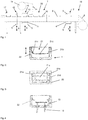
- Figure 1 shows the packaging machine 1 according to the invention, which has a deep-drawing station 2, a filling station 7 and a sealing station 15.
- a plastic film web 8 the so-called bottom film web, is pulled off a supply roll and, preferably in cycles, transported here from right to left along the packaging machine according to the invention. In one cycle, the film web is transported on by one format length.
- the packaging machine has two transport means (not shown), in the present case two endless chains, which are arranged to the right and left of the film web. Each endless chain has holding means which each interact with an edge of the film web.
- At least one gear wheel is provided for each chain, around which the respective chain is deflected. At least one of these gears is driven.
- the gearwheels in the inlet area 19 and / or in the outlet area can be connected to one another, preferably by a rigid shaft.
- Each means of transport has a plurality of clamping means, which grip the bottom film web 8 in the inlet area and transmit the movement of the means of transport to the bottom film web 8.
- the jamming connection between the means of transport and the bottom film web is released again.
- the deep-drawing station 2 which preferably has an upper tool 3 and, according to the invention, a lower tool 4, which has the shape of the packaging tray to be produced, the packaging trays 6 are molded into the bottom film web 8.
- the lower tool 4 is arranged on a lifting table 5 which, as symbolized by the double arrow, is vertically adjustable.
- the lower tool 4 is lowered and then raised again.
- the packaging troughs are then filled with the goods 16 in the filling station 7.
- the subsequent sealing station 19 which also consists of an upper tool 12 and a vertically adjustable lower tool 11, an upper film web is sealed onto the packaging tray.
- the upper tool and / or the lower tool are lowered or raised before and after each film transport.
- the upper film web 14 can also be deep-drawn and / or guided in transport means or transported by transport chains, these transport means then only extending from the sealing station and possibly downstream. Otherwise, the explanations made for the means of transport of the bottom film web apply.
- the finished packaging is also separated, which is done with the cutting tools 17, 18.
- the cutting tool 18 is in the present Case can also be raised or lowered with a lifting device 9.
- the person skilled in the art recognizes that, in one cycle, preferably several packaging troughs are deep-drawn, filled and closed.
- FIGS. 2 and 3 show an embodiment of the deep-drawing tool 4 according to the invention, here the lower tool.
- This has a frame 22 in which there are at least one, preferably a plurality of molded shells 21 which serve as a die for the film web to be deep-drawn.
- this molded shell is now made in several parts, ie it has a plurality of segments 21a to 21d which are at least partially displaceable independently of one another, relative to one another and / or relative to the frame, in particular as shown by the double arrow, are displaceable in the vertical direction.
- the molded shell has a molded shell base 21c and molded shell corner segments 21a, 21b and a molded shell edge 21d.
- the segments 21a, b, d are preferably slidably provided relative to the mold shell bottom 21c.
- the segments each individually or jointly have a drive with which they can be moved up and down in particular.
- the segments and / or the molded shell 21 are provided in such a way that they have means by which the film web can be reversibly connected to one or more segments of the molded shell. This ensures that the movement of the segments is transferred to the film web.
- the movement of the segments is preferably controlled in such a way that the minimum film thickness is not exceeded.
- the drive of the segments can be provided, for example, in such a way that the segments 21a, b, d at least temporarily lag and / or lead and / or are uniform with the movement of the base segment. It is also conceivable that only the segments 21a, b, d are provided so as to be displaceable with respect to the segment 21c, and that it can also be provided rigidly in the frame.
- Figure 4 shows a further representation of the tool according to the Figures 2 and 3 .
- the drive of the segments is shown.
- the molded shell base 21c has a different drive 10 than the edge segments 21 a, b, d.
- the mold shell base has a drive which is provided outside the tool, the movement of the drive being transmitted to the mold shell base by means of a linkage 10.
- the drive of one or more molded shell corners is provided by a drive, which is preferably located within the tool.
- the drive 13 is designed as a so-called Nuremberg scissors, the person skilled in the art understanding that the drive can also be designed differently.
- the drives 10, 13 can preferably be operated independently of one another.
- the packaging machine according to the invention preferably has a control which regulates the movement of the segments of the molded shell automatically, for example on the basis of a predetermined recipe and / or on the basis of the measurement of a sensor.
Description
- Die vorliegende Erfindung betrifft ein Tiefziehwerkzeug für eine Verpackungsmaschine zur Herstellung einer Verpackungsmulde durch Tiefziehen einer Folienbahn, mit mindestens einer Formschale und einem Rahmen. Des Weiteren betrifft die vorliegende Erfindung eine Verpackungsmaschine aufweisend das erfindungsgemäße Werkzeug.
- Verpackungsmaschinen für derartige Werkzeuge sind aus dem Stand der Technik beispielsweise aus der
EP 2073970 B1 , derEP 2539125 B1 , derEP 0 962 386 A1 , derEP 2 570 351 , derDE 11 20 119 B , derDE 20 2008 016989 U1 und derWO 2012100956 A1 , bekannt und werden meist als sogenannte "Form-Fill-Seal-Verpackungsmaschinen" (FFS-Verpackungs-maschinen) bezeichnet. Eine typische FFS-Verpackungsmaschine ist ein sogenannter Tiefziehautomat. Bei derartigen Verpackungsmaschinen wird in eine Folienbahn eine Verpackungsmulde durch Tiefziehen in einer Tiefziehstation eingeformt, sodann mit einem Verpackungsgut gefüllt und dann mit einer Deckelfolie in der Siegelstation verschlossen. Sowohl die Tiefziehstation als auch die Siegelstation weisen jeweils ein Unter-und/oder ein Oberwerkzeug auf, wobei mindestens ein Werkzeug der jeweiligen Station eine Matrize aufweist, in die die Folie geformt wird oder die die Verpackungsmulde beim Siegeln aufnimmt. Beim Tiefziehen verändert sich lokal die Dicke der Folie und es kann vorkommen, dass die Dicke einen kritischen Wert unterschreitet. - Es war deshalb die Aufgabe der vorliegenden Erfindung ein Tiefziehwerkzeug zur Verfügung zu stellen, mit dem die Probleme des Standes der Technik vermieden werden können.
- Gelöst wird die Aufgabe mit einem Tiefziehwerkzeug gemäß Patentanspruch 1.
- Die vorliegende Erfindung betrifft ein Tiefziehwerkzeug für eine Verpackungsmaschine zur Herstellung einer Verpackungsmulde durch Tiefziehen einer Folienbahn, mit mindestens einer Formschale und einem Rahmen. In der Regel weist das Tiefziehwerkzeug eine Mehrzahl von Formschalen auf, da bei Verpackungsmaschinen in der Regel eine Vielzahl von Verpackungsmulden, ein sogenanntes Format aus x Zeilen und y Spalten, gleichzeitig tiefgezogen werden.
- Erfindungsgemäß weist nun jede Formschale mehrere Segmente auf, die getrennt voneinander vorgesehen sind. Beim Tiefziehen wird vorzugsweise zwischen der Formschale und der tiefzuziehenden Folie ein gewisser Unterdruck angelegt, wodurch sich die Folie anfangs elastisch, dann plastisch verformt, bis sie sich bei abgeschlossener Verformung weitestgehend an die Oberfläche der Formschale angelegt hat. Dadurch kühlt die Folie vorzugsweise ab, erstarrt und behält ihre neue Gestalt als fertige Verpackungsmulde auch nach dem Wegnehmen des Unterdrucks zumindest im Wesentlichen bei.
- Die erste Stufe während der Verformung wird oftmals Anmulden genannt, wobei die anfangs im Wesentlichen plane Folie leicht in den Rahmen hinein gewölbt wird, was zumindest anfangs im Bereich elastischer Verformung der Folie geschieht und die Folie typischerweise auch noch nicht oder nur geringfügig in Kontakt mit dem oberen Bereich der Seitenwand des Rahmens kommt. Mit zunehmender Verformung kommt immer mehr Folie in Kontakt mit der Seitenwand des Rahmens, kühlt dabei lokal ab und verliert dort ihre plastische Verformungsfähigkeit, wodurch bei zunehmender Verformung sich eher die noch wärmeren Bereiche der Folie verformen als die bereits etwas abgekühlten und somit die Folie nach unten hin immer dünner wird, je tiefer sie in den Rahmen hineingezogen wird. Knapp unterhalb der oberen Kante der Seitenwand des Rahmens hat die Folie nach Abschluss des Tiefziehprozesses beispielsweise noch ca. 70% ihrer Anfangsdicke, im untersten Bereich des Seitenrandes, also am Übergang zum Boden der Verpackungsmulde jedoch beispielsweise nur noch 25%. Der mittlere Bereich des Bodens weist typischerweise eine viel größere Dicke, beispielsweise 50% Ihrer Anfangsdicke auf, als die weiter außen und in Nähe des Übergangs zur Seitenwand der Verpackung befindlichen Bereiche, zu denen oben bereits ein Beispiel gegeben ist. Im ungünstigsten Fall reißt die Folie an solchen dünnen Stellen ein oder hat dort zumindest eine geringe Formstabilität.
- Der vorliegenden Erfindung liegt die Erkenntnis zugrunde, dass durch die Bewegung der Formschale und/oder mindestens eines Segments der Formschale diese der sich im Verformungsprozess befindlichen Folie entgegenkommt oder sie sogar in ihrer planen Ausgangsstellung abholt und vorzugsweise sogar in Kontakt mit der Folie tritt.
- Die Folie kann durch den Kontakt oder Strahlungskälte, beispielsweise infolge Fast-Kontakt und/oder Kontakt lokal abkühlt und/oder gezielt erhitzt werden und dadurch ihre Verformungswilligkeit lokal reduziert und/oder erhöht oder konstant gehalten werden. Die Bewegungsrichtung der Formschale und/oder zumindest eines Segments wird dann so eingestellt, dass sie der Bewegung der Folie folgt, voreilt und/oder nacheilt, vorzugsweise bis die Verformung der Folie und damit der Tiefzug abgeschlossen ist.
- Die tiefzuziehende Folie kann aber auch zumindest abschnittsweise an einem oder mehreren Segmenten der Formschale haften. Durch eine Bewegung der Formschale und/oder mindestens eines Segmentes der Formschale wird die Folienbahn tiefgezogen oder/und ihre Verformung behindert.
- Ein Stempel, der auf der der Formschale gegenüberliegenden Seite der Folienbahn vorgesehen sein kann, kann das Tiefziehen der Verpackungsmulde insgesamt oder lokal unterstützen und/oder lokal behindern.
- Mehrere dieser Segment(e) weisen einen Antrieb auf, mit dem es möglich ist, das jeweilige Segment relativ zu einem anderen Segment und/oder relativ zu dem Rahmen des Werkzeugs zu verschieben, vorzugsweise entlang einer Geraden und/oder vorzugsweise vertikal. Dadurch ist es möglich einzelne Bereiche der Folienbahn zu unterschiedlichen Zeitpunkten und/oder mit einer unterschiedlichen Geschwindigkeit und/oder um eine unterschiedliche Länge tiefzuziehen, wodurch beispielweise der Materialfluss der Folienbahn beeinflusst wird und kritische minimale Foliendicken vermieden werden und/oder gezielt Materialanhäufungen oder Ausdünnungen in der Folie erzeugt werden.
- Vorzugsweise weist die Formschale mindestens ein Formschalenrandsegment auf. Dabei kann es sich um einen durchgehenden Randbereich in Form eines Rings, der nicht rund sein muss sondern beispielsweise auch vieleckig, insbesondere mit gerundeten Ecken sein kann und/oder um gerade Bereiche und/oder Eckbereiche handeln. Der Formschalenrandbereich umschließt einen oder mehrere separat davon vorgesehene Formschalen-Bodensegment(e). Vorzugsweise ist mindestens ein Folienrandsegment relativ zu mindestens einem Formschalen-Boden-Segment verschieblich vorgesehen. Beispielsweise sind das/die Ecksegment(e) relativ zu dem Formschalen-Boden verschieblich vorgesehen und können diesem beim Tiefziehen, zumindest zeitweise, vor und/oder nacheilen aber auch zumindest zeitweise gleichförmig zu diesem bewegt werden.
- Erfindungsgemäss weisen mindestens zwei Segmente der Formschale jeweils einen Antrieb auf, die unabhängig voneinander betreibbar sind.
- Gemäß einer bevorzugten Ausführungsform sind ein oder mehrere Segmente untereinander und/oder relativ zu dem Rahmen abgedichtet. Diese Abdichtung kann während der Bewegung der Segmente aber auch während des Stillstandes eines oder mehrerer Segmente erfolgen.
- Gemäß einer bevorzugten Ausführungsform der vorliegenden Erfindung weist mindestens ein Segment der Formschale ein oder mehrere Kühl- und/oder Heizmittel auf und/oder es können Zonen gleicher oder unterschiedlicher Temperatur eingestellt werden. Dadurch kann die tiefzuziehende Folienbahn geheizt und/oder gekühlt werden, beispielsweise um Materialfluss zu verbessern oder zu vermindern. Unterschiedliche Teilbereiche der Folienbahn können gleichzeitig oder nacheinander gleich oder unterschiedlich geheizt und/oder gekühlt werden.
- Gemäß einer weiteren erfindungsgemäßen oder bevorzugten Ausführungsform sind die Werkstoffe und/oder Oberflächen der Segmente zumindest teilweise unterschiedlich gestaltet, um maximalen Einfluss auf die Verformungs- und Oberflächeneigenschaften der Folie nehmen zu können.
- Für den Fall, dass ein Stempel das Tiefziehen unterstützt, so kann dieser ebenfalls geheizt und/oder gekühlt werden. Vorzugsweise weist der Stempel ebenfalls Segmente auf, die separat und/oder gemeinsam geheizt und/oder gekühlt werden können.
- Mindestens ein Segment des Stempels kann auch einen Antrieb aufweisen, so dass dieses separat von den anderen Segmenten verschieblich vorgesehen sein kann. Die Bewegung dieses Segments kann das Tiefziehen unterstützen. Es kann separat aber auch in Verbindung mit dem beweglichen Segment der Formschale vorgesehen sein.
- Weiterhin bevorzugt weist mindestens ein Segment der Formschale des Formbodens ein reversibles Haftmittel auf. Beispielsweise ist dieses Haftmittel eine Bohrung oder eine poröse Fläche durch die ein Unterdruck zwischen der Folienbahn und dem jeweiligen Segment erzeugt werden kann, der die Folienbahn reversibel mit der Folienbahn verbindet, so dass die Folienbahn der Bewegung des Segmentes folgt und/oder auch in Richtung des jeweiligen Segments gezogen wird.
- Noch ein Gegenstand der vorliegenden Anmeldung ist eine Verpackungsmaschine mit einer Tiefziehstation und einer Siegelstation und/oder einer Schneideeinrichtung, mit der Verpackungen für Verpackungsgüter hergestellt werden, wobei die Tiefziehstation das erfindungsgemäße Tiefziehwerkzeug aufweist.
- Die vorliegende Erfindung betrifft eine Verpackungsmaschine nach Anspruch 6 zum Verpacken von einem Verpackungsgut, insbesondere einem Lebensmittel, vorzugsweise in einer Kunststofffolie, die auch mehrlagig und aus verschiedenen Werkstoffen bestehend ausgeführt sein kann. Die Verpackung weist eine tiefgezogene Verpackungsmulde auf, die mit dem Verpackungsgut befüllt und dann mit einem Deckel, insbesondere einer Deckelfolie verschlossen wird. Die Deckelfolie wird an die Verpackungsmulde gesiegelt. Vor dem Siegeln kann in der Verpackungsmulde ein Gasaustausch vorgenommen werden. Die Deckelfolie und/oder Zwischenfolienbahn kann ebenfalls tiefgezogen sein, auch gemäß dem Gegenstand der Erfindung. Für den Gasaustausch wird die in der noch nicht verschlossenen Verpackung vorhandene Luft teilweise abgesaugt und dadurch ein Unterdruck in der Verpackung erzeugt, der dann oder gleichzeitig durch ein anderes Gas, beispielsweise Sauerstoff, Stickstoff und/oder Kohlendioxid, ersetzt wird, wobei der Gasaustausch in der Regel in und/oder vor der Siegelstation und vor bzw. vorzugsweise nach dem Befüllen der Verpackungsmulde mit Verpackungsgut stattfindet.
- Die erfindungsgemäße Verpackungsmaschine weist folglich mindestens eine Tiefziehstation auf, die über ein Unter- und/oder ein Oberwerkzeug verfügt, wobei das Unterwerkzeug unterhalb und das Oberwerkzeug oberhalb der Transportebene der Folienbahn, aus der die Verpackungsmulde geformt wird, angeordnet ist.
- An der erfindungsgemäßen Verpackungsmaschine können ein oder mehrere Antriebe vorgesehen sein, die jeweils direkt oder indirekt mit einem oder mehreren der Segmente der Formschale verbunden sein können und diese relativ zueinander und/oder relativ zu dem Rahmen des Formwerkzeuges bewegen. Vorzugsweise werden die Antriebe gemeinsam mit dem Werkzeug vor bzw. nach dem Transport der Folienbahn angehoben bzw. abgesenkt. Gemäß einer weiteren bevorzugten Ausführungsform der vorliegenden Erfindung weist die Verpackungsmaschine Mittel auf, um einen oder mehrere Antriebe, die sich unmittelbar an und/oder in dem erfindungsgemäßen Tiefziehwerkzeug befinden mit Energie, beispielsweise elektrischer Energie oder Druckluft, zu versorgen. Diese(r) Antrieb(e) ist/sind insbesondere dafür vorgesehen jeweils ein oder mehrere Segmente relativ zueinander oder relativ zu dem Rahmen des Werkzeugs zu bewegen.
- Gemäß einer bevorzugten Ausführungsform der vorliegenden Erfindung weist die Verpackungsmaschine Mittel auf, um die Folie für das Tiefziehen vorzubereiteten, z. B. erwärmte Folie entgegen der späteren Tiefziehrichtung, also beispielsweise nach oben vorzugsweise gezielt vorzurecken, indem die Folie beispielsweise durch ein Vakuummittel um einen bestimmt Betrag etwa domartig nach oben geführt wird, wodurch zumindest bestimmte Bereiche, beispielsweise die den späteren oberen Rand der Verpackung bildenden Bereiche plastisch vorverformt werden, um ein gezieltes ausdünnen der ansonsten eher dickeren Bereiche zu erzielen.
- Ein weiterer Gegenstand, der nicht erfindungsgemäss ist, ist ein Verfahren zum Tiefziehen einer Verpackungsmulde in eine Folienbahn mit einem Tiefziehwerkzeug, mit einer Formschale, die mehrere Segmente aufweist, wobei ein Segment während des Tiefziehens relativ zu einem anderen Segment und/oder mindestens ein Segment relativ zu einem Rahmen verschoben wird.
- Vorzugsweise wird die Bewegung des/der Segmente(s) so gesteuert, dass dadurch die Restfoliendicke, insbesondere in Bereichen, die sehr stark tiefgezogen werden, beispielsweise Eckabschnitte einer Verpackungsmulde, gesteuert wird. So kann beispielsweise Folienmaterial aus benachbarten Bereichen in stark tiefgezogene Bereiche fließen und dadurch verhindert werden, dass eine minimal zulässige Foliendicke unterschritten wird. Auch kann die Ausgangsfoliendicke dünner gestaltet und somit Ressourcen und Kosten gespart werden.
- Vorzugsweise wird die Bewegung der Segmente und/oder die Verbindung zwischen dem Segment und Folienbahn selbsttätig gesteuert/geregelt wird, beispielweise indem ein entsprechendes Programm in der Steuerung der Verpackungsmaschine hinterlegt ist, das die Bewegung jedes beweglichen Segments steuert oder regelt. Es kann aber auch ein oder mehrere Sensoren vorhanden sein, beispielsweise ein Foliendickensensor und dass das Signal dieses Sensors zur Bewegung jedes beweglichen Segments eingesetzt wird.
- Vorzugsweise wird die Folienbahn abschnittsweise/lokal gekühlt oder erwärmt. Dies erfolgt insbesondere abgestimmt auf die Bewegung des/der Segmente(s).
- Im Folgenden wird die Erfindung anhand der Figuren erläutert. Diese Erläuterungen sind lediglich beispielhaft und schränken den allgemeinen Erfindungsgedanken nicht ein. Die Erläuterungen gelten für alle Gegenstände der vorliegenden Erfindung gleichermaßen.
- Figur 1
- zeigt die erfindungsgemäße Verpackungsmaschine
- Figuren 2 - 4
- zeigen eine Ausführungsform des Tiefziehwerkzeugs
-
Figur 1 zeigt die erfindungsgemäße Verpackungsmaschine 1, die eine Tiefziehstation 2, eine Füllstation 7 sowie eine Siegelstation 15 aufweist. Eine Kunststofffolienbahn 8, die sogenannte Unterfolienbahn, wird von einer Vorratsrolle abgezogen und, vorzugsweise taktweise, entlang der erfindungsgemäßen Verpackungsmaschine hier von rechts nach links transportiert. Bei einem Takt wird die Folienbahn um eine Formatlänge weitertransportiert. Dafür weist die Verpackungsmaschine zwei Transportmittel (nicht dargestellt), in dem vorliegenden Fall jeweils zwei Endlosketten auf, die rechts und links von der Folienbahn angeordnet sind. Jede Endloskette weist Haltemittel auf, die jeweils mit einer Kante der Folienbahn zusammenwirken. Sowohl am Anfang als auch am Ende der Verpackungsmaschine ist für jede Kette jeweils mindestens ein Zahnrad vorgesehen, um das die jeweilige Kette umgelenkt wird. Mindestens eines dieser Zahnräder ist angetrieben. Die Zahnräder im Einlaufbereich 19 und/oder im Auslaufbereich können miteinander, vorzugsweise durch eine starre Welle, verbunden sein. Jedes Transportmittel weist eine Vielzahl von Klemmmitteln auf, die die Unterfolienbahn 8 im Einlaufbereich klemmend ergreifen und die Bewegung des Transportmittels auf die Unterfolienbahn 8 übertragen. Im Auslaufbereich der Verpackungsmaschine wird die klemmende Verbindung zwischen dem Transportmittel und der Unterfolienbahn wieder gelöst. In der Tiefziehstation 2, die vorzugsweise über ein Oberwerkzeug 3 und erfindungsgemäß ein Unterwerkzeug 4 verfügt, das die Form der herzustellenden Verpackungsmulde aufweist, werden die Verpackungsmulden 6 in die Unterfolienbahn 8 eingeformt. Das Unterwerkzeug 4 ist auf einem Hubtisch 5 angeordnet, der, wie durch den Doppelpfeil symbolisiert wird, vertikal verstellbar ist. Vor jedem Folienvorschub wird das Unterwerkzeug 4 abgesenkt und danach wieder angehoben. Im weiteren Verlauf der Verpackungsmaschine werden die Verpackungsmulden dann in der Füllstation 7 mit dem Verpackungsgut 16 gefüllt. In der sich daran anschließenden Siegelstation 19, die ebenfalls aus einem Oberwerkzeug 12 und einem vertikal verstellbaren Unterwerkzeug 11 besteht, wird eine Oberfolienbahn auf die Verpackungsmulde gesiegelt. Auch in der Siegelstation werden das Oberwerkzeug und/oder das Unterwerkzeug vor und nach jedem Folientransport abgesenkt bzw. angehoben. Auch die Oberfolienbahn 14 kann tiefgezogen und/oder in Transportmitteln geführt sein bzw. von Transportketten transportiert werden, wobei sich diese Transportmittel dann nur von der Siegelstation und ggf. stromabwärts erstrecken. Ansonsten gelten die Ausführungen, die zu dem Transportmitteln der Unterfolienbahn gemacht wurden. Im weiteren Verlauf der Verpackungsmaschine werden auch die fertiggestellten Verpackungen vereinzelt, was mit dem Schneidwerkzeugen 17, 18 erfolgt. Das Schneidwerkzeug 18 ist in dem vorliegenden Fall ebenfalls mit einer Hubeinrichtung 9 anhebbar bzw. absenkbar. Der Fachmann erkennt, dass bei einem Takt vorzugsweise mehrere Verpackungsmulden tiefgezogen, befüllt und verschlossen werden. - Die
Figuren 2 und 3 zeigen eine Ausführungsform des erfindungsgemäßen Tiefziehwerkzeugs 4, hier des Unterwerkzeugs. Dies weist einen Rahmen 22 auf, in dem sich mindestens eine, vorzugsweise mehrere Formschalen 21 befinden, die als Matrize für die tiefzuziehende Folienbahn dienen. Erfindungsgemäß ist diese Formschale nun mehrteilig ausgeführt, d.h. sie weist mehrere Segmente 21a bis 21d auf, die zumindest teilweise unabhängig voneinander, relativ zueinander und/oder relativ zu dem Rahmen verschiebbar, insbesondere wie durch den Doppelpfeil dargestellt, in vertikaler Richtung verschiebbar vorgesehen sind. In dem vorliegenden Fall weist die Formschale einen Formalschalen-Boden 21c sowie Formschalen-Ecksegmente 21a, 21 b sowie einen Formschalen-Rand 21 d auf. Die Segmente 21a, b, d sind vorzugsweise relativ zu dem Formschalen-Boden 21c verschieblich vorgesehen. Dafür weisen die Segmente jeweils einzeln oder gemeinsam einen Antrieb auf, mit dem sie insbesondere rauf und runter bewegt werden können. Desweiteren sind die Segmente und/oder die Formschale 21 so vorgesehen, dass sie Mittel aufweist, mit dem die Folienbahn reversibel mit einem oder mehreren Segmenten der Formschale verbindbar ist. Dadurch wird erreicht, dass die Bewegung der Segmente auf die Folienbahn übertragen wird. Vorzugsweise wird die Bewegung der Segmente so gesteuert, dass die Unterschreitung einer minimalen Foliendicke verhindert wird. Dafür kann der Antrieb der Segmente, beispielsweise so vorgesehen sein, dass die Segmente 21a, b, d der Bewegung des Bodensegments zumindest zeitweise nach- und/oder voreilen und/oder mit dieser gleichförmig ist. Es ist auch vorstellbar, dass lediglich die Segmente 21a, b, d verschieblich zu dem Segment 21c vorgesehen sind, dass auch starr in dem Rahmen vorgesehen sein kann. -
Figur 4 zeigt eine weitere Darstellung des Werkzeugs gemäß denFiguren 2 und 3 . In dem vorliegenden Fall ist der Antrieb der Segmente dargestellt. Es ist zu erkennen, dass der Formschalenboden 21c einen anderen Antrieb 10 aufweist, als die Randsegmente 21 a, b, d. In dem vorliegenden Fall weist der Formschalen-Boden einen Antrieb auf, der außerhalb des Werkzeugs vorgesehen ist, wobei die Bewegung des Antriebs auf den Formschalen-Boden mittels eines Gestänges 10 übertragen wird. Der Antrieb eines oder mehrerer Formschalen-Ecken ist durch einen Antrieb vorgesehen, der sich vorzugsweise innerhalb des Werkzeuges befinden. In dem dargestellten Fall ist der Antrieb 13 als sogenannte Nürnberger-Schere ausgebildet, wobei der Fachmann versteht, dass der Antrieb auch anders ausgeführt sein kann. Die Antriebe 10, 13 sind vorzugsweise unabhängig voneinander betreibbar. - Vorzugsweise weist die erfindungsgemäße Verpackungsmaschine eine Steuerung/Regelung auf, die die Bewegung der Segmente der Formschale automatisch regelt, beispielsweise aufgrund eines vorgegebenen Rezepts und/oder aufgrund der Messung eines Sensors.
-
- 1
- Verpackungsmaschine
- 2
- Formstation, Tiefziehstation
- 3
- Oberwerkzeug der Tiefziehstation
- 4
- Unterwerkzeug der Tiefziehstation
- 5
- Hubtisch, Träger eines Werkzeugs der Siegel-, Tiefziehstation und/oder der Schneideinrichtung
- 6
- Verpackungsmulde
- 7
- Füllstation
- 8
- Folienbahn, Unterfolienbahn
- 9
- Hubeinrichtung
- 10
- Antrieb, Höhenverstellung
- 11
- Unterwerkzeug der Siegelstation
- 12
- Oberwerkzeug der Siegelstation
- 13
- Antrieb, Höhenverstellung
- 14
- Oberfolienbahn, Deckelfolie
- 15
- Siegelstation
- 16
- Verpackungsgut
- 17
- Längsschneider
- 18
- Querschneider
- 19
- Einlaufbereich
- 20
- Einlegestation
- 21
- Formschale
- 21a
- Segment der Formschale, Formschalenrand, Formschalen-Ecke
- 21b
- Segment der Formschale, Formschalenrand, Formschalen-Ecke
- 21c
- Segment der Formschale, Formschalen-Boden
- 21d
- Segment der Formschale, Formschalenrand
- 22
- Rahmen
Claims (6)
- Tiefziehwerkzeug (4) für eine Verpackungsmaschine (1) zur Herstellung einer Verpackungsmulde (6) durch Tiefziehen einer Folienbahn (8), mit mindestens einer Formschale (21) und einem Rahmen (22), dadurch gekennzeichnet, dass jede Formschale mehrere Segmente 21a - d) aufweist, von denen mindestens zwei Segmente (21a, 21c) jeweils einen Antrieb (10, 13) aufweisen, mit dem es relativ zu dem anderen Segment und/oder dem Rahmen verschiebbar ist, wobei die Antriebe unabhängig voneinander betreibbar sind.
- Tiefziehwerkzeug (4) nach Anspruch 1, dadurch gekennzeichnet, dass die Formschale (21) mindestens ein Formschalenrandsegment (21a, 21b, 21d), relativ zu dem Formschalen-Boden (21c) verschieblich vorgesehen ist.
- Tiefziehwerkzeug (4) nach einem der voranstehenden Ansprüche, dadurch gekennzeichnet, dass die Segmente untereinander und/oder relativ zu dem Rahmen (22) abgedichtet sind.
- Tiefziehwerkzeug (4) nach einem der voranstehenden Ansprüche, dadurch gekennzeichnet, dass mindestens ein Segment ein Kühl- und/oder Heizmittel aufweist.
- Tiefziehwerkzeug nach einem der voranstehenden Ansprüche, dadurch gekennzeichnet, dass mindestens ein Segment ein reversibles Haftmittel aufweist.
- Verpackungsmaschine (1) mit einer Tiefziehstation (2) und einer Siegelstation (19) und/oder einer Schneideeinrichtung (27), mit der Verpackungen für Verpackungsgüter hergestellt werden, wobei die Tiefziehstation ein Tiefziehwerkzeug gemäß einem der voranstehenden Ansprüche aufweist.
Applications Claiming Priority (2)
| Application Number | Priority Date | Filing Date | Title |
|---|---|---|---|
| DE102015225490 | 2015-12-16 | ||
| PCT/EP2016/080626 WO2017102643A1 (de) | 2015-12-16 | 2016-12-12 | Formwerkzeug mit geteilter formschale |
Publications (2)
| Publication Number | Publication Date |
|---|---|
| EP3390234A1 EP3390234A1 (de) | 2018-10-24 |
| EP3390234B1 true EP3390234B1 (de) | 2020-04-15 |
Family
ID=57539263
Family Applications (1)
| Application Number | Title | Priority Date | Filing Date |
|---|---|---|---|
| EP16809395.3A Active EP3390234B1 (de) | 2015-12-16 | 2016-12-12 | Formwerkzeug mit geteilter formschale |
Country Status (3)
| Country | Link |
|---|---|
| EP (1) | EP3390234B1 (de) |
| ES (1) | ES2794902T3 (de) |
| WO (1) | WO2017102643A1 (de) |
Cited By (2)
| Publication number | Priority date | Publication date | Assignee | Title |
|---|---|---|---|---|
| EP3875246A1 (de) * | 2020-03-06 | 2021-09-08 | Harro Höfliger Verpackungsmaschinen GmbH | Tiefziehvorrichtung, verpackungsmaschine mit einer tiefziehvorrichtung und verfahren zum betrieb der tiefziehvorrichtung |
| WO2023078918A1 (de) * | 2021-11-05 | 2023-05-11 | Gea Food Solutions Germany Gmbh | Verpackungsmaschine mit einem gekühlten formwerkzeug |
Families Citing this family (2)
| Publication number | Priority date | Publication date | Assignee | Title |
|---|---|---|---|---|
| DE102019200998A1 (de) * | 2019-01-28 | 2020-07-30 | Multivac Sepp Haggenmüller Se & Co. Kg | Tiefziehverpackungsmaschine mit Formstation |
| DE102019004970A1 (de) * | 2019-07-18 | 2021-01-21 | Kiefel Gmbh | Thermoformwerkzeug, thermoformstation, anlage zum herstellen eines thermogeformten formteils und verfahren zum herstellen eines thermogeformten formteils |
Family Cites Families (6)
| Publication number | Priority date | Publication date | Assignee | Title |
|---|---|---|---|---|
| DE1120119B (de) * | 1955-11-03 | 1961-12-21 | Max Braun Fa | Verfahren und Vorrichtung zum Herstellen eines offenen Hohlkoerpers nach Art einer Schale aus einer Folie oder Platte aus organischem thermoplastischem Kunststoff nach der Methode des Vakuum-Tiefziehens |
| DE1586131A1 (de) * | 1966-09-12 | 1970-06-25 | Inst Nahrungsmittel Genussmitt | Verfahren und Vorrichtung zum Herstellen und Verschliessen von Plastbehaeltern |
| DE19824588A1 (de) * | 1998-06-02 | 1999-12-09 | Kraemer & Grebe Kg | Matrize und Verfahren zur Herstellung einer Verpackungsmulde mit Hinterschnitt |
| DE202008016989U1 (de) * | 2008-12-23 | 2009-03-12 | Capriotti, Luciano | Vorrichtung zur Verbesserung des Wärmeübergangs bei Folien in Tiefziehautomaten insbesondere Verpackungsmaschinen |
| ES2534655T3 (es) * | 2011-09-16 | 2015-04-27 | Multivac Sepp Haggenmüller Gmbh & Co. Kg | Máquina para embutición profunda de envases para la fabricación de envases verticales con ahuecamiento conformado |
| MX354250B (es) * | 2012-02-22 | 2018-02-19 | Henkel IP & Holding GmbH | Mecanizado para fabricar una bolsa de dosis unitaria. |
-
2016
- 2016-12-12 EP EP16809395.3A patent/EP3390234B1/de active Active
- 2016-12-12 ES ES16809395T patent/ES2794902T3/es active Active
- 2016-12-12 WO PCT/EP2016/080626 patent/WO2017102643A1/de active Application Filing
Non-Patent Citations (1)
| Title |
|---|
| None * |
Cited By (2)
| Publication number | Priority date | Publication date | Assignee | Title |
|---|---|---|---|---|
| EP3875246A1 (de) * | 2020-03-06 | 2021-09-08 | Harro Höfliger Verpackungsmaschinen GmbH | Tiefziehvorrichtung, verpackungsmaschine mit einer tiefziehvorrichtung und verfahren zum betrieb der tiefziehvorrichtung |
| WO2023078918A1 (de) * | 2021-11-05 | 2023-05-11 | Gea Food Solutions Germany Gmbh | Verpackungsmaschine mit einem gekühlten formwerkzeug |
Also Published As
| Publication number | Publication date |
|---|---|
| ES2794902T3 (es) | 2020-11-19 |
| WO2017102643A1 (de) | 2017-06-22 |
| EP3390234A1 (de) | 2018-10-24 |
Similar Documents
| Publication | Publication Date | Title |
|---|---|---|
| EP3390234B1 (de) | Formwerkzeug mit geteilter formschale | |
| EP2073970B1 (de) | Heizplatte mit einer vielzahl von heizpatronen | |
| EP2251264B1 (de) | Verpackungsmaschine und Verfahren zum Verschließen von Behältern mit Deckeln | |
| EP1984250B1 (de) | Verpackungsmaschine für die herstellung einer verpackung mit einem rücksprung in dem verpackungsmuldenrand | |
| EP2819831B1 (de) | Verpackungsmaschine mit einem auswechselbaren werkzeug | |
| EP3140200B1 (de) | Verfahren und vorrichtung zur herstellung von formteilen aus einer faserwerkstoffbahn | |
| EP0710605B1 (de) | Verfahren und Vorrichtung zum Maximieren der Taktgeschwindigkeit einer Vakuumverpackungsmaschine | |
| EP2444324B1 (de) | Tiefziehverpackungsmaschine und Verfahren zum Recken einer Folienbahn | |
| WO2017001114A1 (de) | Verfahren zum verbinden eines strukturelements mit einer verpackungsmulde | |
| EP3405399B1 (de) | Siegelwerkzeug, verpackungmachine und verfahren zur herstellung eine skinverpackung | |
| EP3294636B1 (de) | Verpackungsmaschine mit einer hubvorrichtung | |
| WO2008043572A1 (de) | Werkzeug mit einem linearantrieb | |
| DE102010019576A1 (de) | Verpackungsmaschine mit einem auswechselbaren Antrieb der Hubeinrichtung | |
| EP2684803B1 (de) | Verfahren zum Herstellen einer Verpackung | |
| WO2011127613A1 (de) | Anordnung zur bildung einer bandschlaufe und verfahren und vorrichtung zur herstellung von aufreissdeckeln | |
| EP2729375B1 (de) | Verpackungsmaschine mit einem mittel zur befestigung einer einlage an einem strukturelement | |
| EP3380405B1 (de) | Reduzierung des kammervolumens bei ziehtiefenanpassung in der siegelstation mittels einer aufblasbaren dichtung | |
| WO2022002968A2 (de) | Siegelwerkzeug mit einem heizmittel | |
| EP3009355B1 (de) | Verfahren zum Herstellen einer Verpackung | |
| DE102013101055A1 (de) | Verfahren und Vorrichtung zum Tiefziehen | |
| EP3860917A1 (de) | Hub für ein topform-werkzeug | |
| DE102017101210A1 (de) | Verpackungsmaschine mit einer Hubvorrichtung | |
| EP3319881A1 (de) | Verpackungsmaschine mit reststreifenentsorgung | |
| WO2016091516A1 (de) | Verfahren zur anordnung von zwei beschichtungen auf einer deckelfolie | |
| WO2014195370A1 (de) | Verpackungsmaschine mit einem heizmittel |
Legal Events
| Date | Code | Title | Description |
|---|---|---|---|
| STAA | Information on the status of an ep patent application or granted ep patent |
Free format text: STATUS: UNKNOWN |
|
| STAA | Information on the status of an ep patent application or granted ep patent |
Free format text: STATUS: THE INTERNATIONAL PUBLICATION HAS BEEN MADE |
|
| PUAI | Public reference made under article 153(3) epc to a published international application that has entered the european phase |
Free format text: ORIGINAL CODE: 0009012 |
|
| STAA | Information on the status of an ep patent application or granted ep patent |
Free format text: STATUS: REQUEST FOR EXAMINATION WAS MADE |
|
| 17P | Request for examination filed |
Effective date: 20180611 |
|
| AK | Designated contracting states |
Kind code of ref document: A1 Designated state(s): AL AT BE BG CH CY CZ DE DK EE ES FI FR GB GR HR HU IE IS IT LI LT LU LV MC MK MT NL NO PL PT RO RS SE SI SK SM TR |
|
| AX | Request for extension of the european patent |
Extension state: BA ME |
|
| DAV | Request for validation of the european patent (deleted) | ||
| DAX | Request for extension of the european patent (deleted) | ||
| STAA | Information on the status of an ep patent application or granted ep patent |
Free format text: STATUS: EXAMINATION IS IN PROGRESS |
|
| 17Q | First examination report despatched |
Effective date: 20190502 |
|
| GRAP | Despatch of communication of intention to grant a patent |
Free format text: ORIGINAL CODE: EPIDOSNIGR1 |
|
| STAA | Information on the status of an ep patent application or granted ep patent |
Free format text: STATUS: GRANT OF PATENT IS INTENDED |
|
| INTG | Intention to grant announced |
Effective date: 20191115 |
|
| GRAS | Grant fee paid |
Free format text: ORIGINAL CODE: EPIDOSNIGR3 |
|
| GRAA | (expected) grant |
Free format text: ORIGINAL CODE: 0009210 |
|
| STAA | Information on the status of an ep patent application or granted ep patent |
Free format text: STATUS: THE PATENT HAS BEEN GRANTED |
|
| AK | Designated contracting states |
Kind code of ref document: B1 Designated state(s): AL AT BE BG CH CY CZ DE DK EE ES FI FR GB GR HR HU IE IS IT LI LT LU LV MC MK MT NL NO PL PT RO RS SE SI SK SM TR |
|
| REG | Reference to a national code |
Ref country code: CH Ref legal event code: EP |
|
| REG | Reference to a national code |
Ref country code: DE Ref legal event code: R096 Ref document number: 502016009595 Country of ref document: DE |
|
| REG | Reference to a national code |
Ref country code: IE Ref legal event code: FG4D Free format text: LANGUAGE OF EP DOCUMENT: GERMAN |
|
| REG | Reference to a national code |
Ref country code: AT Ref legal event code: REF Ref document number: 1257007 Country of ref document: AT Kind code of ref document: T Effective date: 20200515 |
|
| REG | Reference to a national code |
Ref country code: NL Ref legal event code: MP Effective date: 20200415 |
|
| REG | Reference to a national code |
Ref country code: LT Ref legal event code: MG4D |
|
| PG25 | Lapsed in a contracting state [announced via postgrant information from national office to epo] |
Ref country code: GR Free format text: LAPSE BECAUSE OF FAILURE TO SUBMIT A TRANSLATION OF THE DESCRIPTION OR TO PAY THE FEE WITHIN THE PRESCRIBED TIME-LIMIT Effective date: 20200716 Ref country code: NO Free format text: LAPSE BECAUSE OF FAILURE TO SUBMIT A TRANSLATION OF THE DESCRIPTION OR TO PAY THE FEE WITHIN THE PRESCRIBED TIME-LIMIT Effective date: 20200715 Ref country code: LT Free format text: LAPSE BECAUSE OF FAILURE TO SUBMIT A TRANSLATION OF THE DESCRIPTION OR TO PAY THE FEE WITHIN THE PRESCRIBED TIME-LIMIT Effective date: 20200415 Ref country code: SE Free format text: LAPSE BECAUSE OF FAILURE TO SUBMIT A TRANSLATION OF THE DESCRIPTION OR TO PAY THE FEE WITHIN THE PRESCRIBED TIME-LIMIT Effective date: 20200415 Ref country code: NL Free format text: LAPSE BECAUSE OF FAILURE TO SUBMIT A TRANSLATION OF THE DESCRIPTION OR TO PAY THE FEE WITHIN THE PRESCRIBED TIME-LIMIT Effective date: 20200415 Ref country code: PT Free format text: LAPSE BECAUSE OF FAILURE TO SUBMIT A TRANSLATION OF THE DESCRIPTION OR TO PAY THE FEE WITHIN THE PRESCRIBED TIME-LIMIT Effective date: 20200817 Ref country code: FI Free format text: LAPSE BECAUSE OF FAILURE TO SUBMIT A TRANSLATION OF THE DESCRIPTION OR TO PAY THE FEE WITHIN THE PRESCRIBED TIME-LIMIT Effective date: 20200415 Ref country code: IS Free format text: LAPSE BECAUSE OF FAILURE TO SUBMIT A TRANSLATION OF THE DESCRIPTION OR TO PAY THE FEE WITHIN THE PRESCRIBED TIME-LIMIT Effective date: 20200815 |
|
| REG | Reference to a national code |
Ref country code: ES Ref legal event code: FG2A Ref document number: 2794902 Country of ref document: ES Kind code of ref document: T3 Effective date: 20201119 |
|
| PG25 | Lapsed in a contracting state [announced via postgrant information from national office to epo] |
Ref country code: HR Free format text: LAPSE BECAUSE OF FAILURE TO SUBMIT A TRANSLATION OF THE DESCRIPTION OR TO PAY THE FEE WITHIN THE PRESCRIBED TIME-LIMIT Effective date: 20200415 Ref country code: LV Free format text: LAPSE BECAUSE OF FAILURE TO SUBMIT A TRANSLATION OF THE DESCRIPTION OR TO PAY THE FEE WITHIN THE PRESCRIBED TIME-LIMIT Effective date: 20200415 Ref country code: RS Free format text: LAPSE BECAUSE OF FAILURE TO SUBMIT A TRANSLATION OF THE DESCRIPTION OR TO PAY THE FEE WITHIN THE PRESCRIBED TIME-LIMIT Effective date: 20200415 Ref country code: BG Free format text: LAPSE BECAUSE OF FAILURE TO SUBMIT A TRANSLATION OF THE DESCRIPTION OR TO PAY THE FEE WITHIN THE PRESCRIBED TIME-LIMIT Effective date: 20200715 |
|
| PG25 | Lapsed in a contracting state [announced via postgrant information from national office to epo] |
Ref country code: AL Free format text: LAPSE BECAUSE OF FAILURE TO SUBMIT A TRANSLATION OF THE DESCRIPTION OR TO PAY THE FEE WITHIN THE PRESCRIBED TIME-LIMIT Effective date: 20200415 |
|
| REG | Reference to a national code |
Ref country code: DE Ref legal event code: R097 Ref document number: 502016009595 Country of ref document: DE |
|
| PG25 | Lapsed in a contracting state [announced via postgrant information from national office to epo] |
Ref country code: CZ Free format text: LAPSE BECAUSE OF FAILURE TO SUBMIT A TRANSLATION OF THE DESCRIPTION OR TO PAY THE FEE WITHIN THE PRESCRIBED TIME-LIMIT Effective date: 20200415 Ref country code: IT Free format text: LAPSE BECAUSE OF FAILURE TO SUBMIT A TRANSLATION OF THE DESCRIPTION OR TO PAY THE FEE WITHIN THE PRESCRIBED TIME-LIMIT Effective date: 20200415 Ref country code: RO Free format text: LAPSE BECAUSE OF FAILURE TO SUBMIT A TRANSLATION OF THE DESCRIPTION OR TO PAY THE FEE WITHIN THE PRESCRIBED TIME-LIMIT Effective date: 20200415 Ref country code: SM Free format text: LAPSE BECAUSE OF FAILURE TO SUBMIT A TRANSLATION OF THE DESCRIPTION OR TO PAY THE FEE WITHIN THE PRESCRIBED TIME-LIMIT Effective date: 20200415 Ref country code: EE Free format text: LAPSE BECAUSE OF FAILURE TO SUBMIT A TRANSLATION OF THE DESCRIPTION OR TO PAY THE FEE WITHIN THE PRESCRIBED TIME-LIMIT Effective date: 20200415 Ref country code: DK Free format text: LAPSE BECAUSE OF FAILURE TO SUBMIT A TRANSLATION OF THE DESCRIPTION OR TO PAY THE FEE WITHIN THE PRESCRIBED TIME-LIMIT Effective date: 20200415 |
|
| PLBE | No opposition filed within time limit |
Free format text: ORIGINAL CODE: 0009261 |
|
| STAA | Information on the status of an ep patent application or granted ep patent |
Free format text: STATUS: NO OPPOSITION FILED WITHIN TIME LIMIT |
|
| PG25 | Lapsed in a contracting state [announced via postgrant information from national office to epo] |
Ref country code: PL Free format text: LAPSE BECAUSE OF FAILURE TO SUBMIT A TRANSLATION OF THE DESCRIPTION OR TO PAY THE FEE WITHIN THE PRESCRIBED TIME-LIMIT Effective date: 20200415 Ref country code: SK Free format text: LAPSE BECAUSE OF FAILURE TO SUBMIT A TRANSLATION OF THE DESCRIPTION OR TO PAY THE FEE WITHIN THE PRESCRIBED TIME-LIMIT Effective date: 20200415 |
|
| 26N | No opposition filed |
Effective date: 20210118 |
|
| PG25 | Lapsed in a contracting state [announced via postgrant information from national office to epo] |
Ref country code: SI Free format text: LAPSE BECAUSE OF FAILURE TO SUBMIT A TRANSLATION OF THE DESCRIPTION OR TO PAY THE FEE WITHIN THE PRESCRIBED TIME-LIMIT Effective date: 20200415 |
|
| GBPC | Gb: european patent ceased through non-payment of renewal fee |
Effective date: 20201212 |
|
| PG25 | Lapsed in a contracting state [announced via postgrant information from national office to epo] |
Ref country code: MC Free format text: LAPSE BECAUSE OF FAILURE TO SUBMIT A TRANSLATION OF THE DESCRIPTION OR TO PAY THE FEE WITHIN THE PRESCRIBED TIME-LIMIT Effective date: 20200415 |
|
| REG | Reference to a national code |
Ref country code: BE Ref legal event code: MM Effective date: 20201231 |
|
| PG25 | Lapsed in a contracting state [announced via postgrant information from national office to epo] |
Ref country code: IE Free format text: LAPSE BECAUSE OF NON-PAYMENT OF DUE FEES Effective date: 20201212 Ref country code: LU Free format text: LAPSE BECAUSE OF NON-PAYMENT OF DUE FEES Effective date: 20201212 |
|
| PG25 | Lapsed in a contracting state [announced via postgrant information from national office to epo] |
Ref country code: GB Free format text: LAPSE BECAUSE OF NON-PAYMENT OF DUE FEES Effective date: 20201212 |
|
| PG25 | Lapsed in a contracting state [announced via postgrant information from national office to epo] |
Ref country code: TR Free format text: LAPSE BECAUSE OF FAILURE TO SUBMIT A TRANSLATION OF THE DESCRIPTION OR TO PAY THE FEE WITHIN THE PRESCRIBED TIME-LIMIT Effective date: 20200415 Ref country code: MT Free format text: LAPSE BECAUSE OF FAILURE TO SUBMIT A TRANSLATION OF THE DESCRIPTION OR TO PAY THE FEE WITHIN THE PRESCRIBED TIME-LIMIT Effective date: 20200415 Ref country code: CY Free format text: LAPSE BECAUSE OF FAILURE TO SUBMIT A TRANSLATION OF THE DESCRIPTION OR TO PAY THE FEE WITHIN THE PRESCRIBED TIME-LIMIT Effective date: 20200415 |
|
| PG25 | Lapsed in a contracting state [announced via postgrant information from national office to epo] |
Ref country code: MK Free format text: LAPSE BECAUSE OF FAILURE TO SUBMIT A TRANSLATION OF THE DESCRIPTION OR TO PAY THE FEE WITHIN THE PRESCRIBED TIME-LIMIT Effective date: 20200415 |
|
| PG25 | Lapsed in a contracting state [announced via postgrant information from national office to epo] |
Ref country code: BE Free format text: LAPSE BECAUSE OF NON-PAYMENT OF DUE FEES Effective date: 20201231 |
|
| PGFP | Annual fee paid to national office [announced via postgrant information from national office to epo] |
Ref country code: ES Payment date: 20230119 Year of fee payment: 7 Ref country code: CH Payment date: 20230103 Year of fee payment: 7 |
|
| P01 | Opt-out of the competence of the unified patent court (upc) registered |
Effective date: 20230513 |
|
| PGFP | Annual fee paid to national office [announced via postgrant information from national office to epo] |
Ref country code: FR Payment date: 20231219 Year of fee payment: 8 Ref country code: DE Payment date: 20231219 Year of fee payment: 8 Ref country code: AT Payment date: 20231219 Year of fee payment: 8 |
|
| PGFP | Annual fee paid to national office [announced via postgrant information from national office to epo] |
Ref country code: ES Payment date: 20240118 Year of fee payment: 8 |