EP3389981B1 - Remote controller for controlling apparatus by diverting feedback signal from native controller to the remote controller and methods for same - Google Patents
Remote controller for controlling apparatus by diverting feedback signal from native controller to the remote controller and methods for same Download PDFInfo
- Publication number
- EP3389981B1 EP3389981B1 EP16820424.6A EP16820424A EP3389981B1 EP 3389981 B1 EP3389981 B1 EP 3389981B1 EP 16820424 A EP16820424 A EP 16820424A EP 3389981 B1 EP3389981 B1 EP 3389981B1
- Authority
- EP
- European Patent Office
- Prior art keywords
- pressure
- signal
- injection molding
- feedback signal
- melt pressure
- Prior art date
- Legal status (The legal status is an assumption and is not a legal conclusion. Google has not performed a legal analysis and makes no representation as to the accuracy of the status listed.)
- Active
Links
- 238000000034 method Methods 0.000 title claims description 38
- 238000001746 injection moulding Methods 0.000 claims description 71
- 239000000155 melt Substances 0.000 claims description 57
- 238000002347 injection Methods 0.000 claims description 47
- 239000007924 injection Substances 0.000 claims description 47
- 238000004891 communication Methods 0.000 claims description 15
- 238000009420 retrofitting Methods 0.000 claims description 6
- 230000004044 response Effects 0.000 claims description 4
- 230000005540 biological transmission Effects 0.000 claims description 2
- 239000012815 thermoplastic material Substances 0.000 description 17
- 239000000463 material Substances 0.000 description 9
- 238000000465 moulding Methods 0.000 description 9
- 230000008569 process Effects 0.000 description 7
- 239000004033 plastic Substances 0.000 description 5
- 238000012986 modification Methods 0.000 description 4
- 230000004048 modification Effects 0.000 description 4
- 229920001169 thermoplastic Polymers 0.000 description 4
- 238000012937 correction Methods 0.000 description 3
- 238000001514 detection method Methods 0.000 description 3
- 238000010586 diagram Methods 0.000 description 3
- 239000008188 pellet Substances 0.000 description 3
- 239000004416 thermosoftening plastic Substances 0.000 description 3
- 230000007274 generation of a signal involved in cell-cell signaling Effects 0.000 description 2
- 238000004519 manufacturing process Methods 0.000 description 2
- 238000005259 measurement Methods 0.000 description 2
- 238000002844 melting Methods 0.000 description 2
- 230000008018 melting Effects 0.000 description 2
- 238000012544 monitoring process Methods 0.000 description 2
- 238000004364 calculation method Methods 0.000 description 1
- 230000008859 change Effects 0.000 description 1
- 230000001419 dependent effect Effects 0.000 description 1
- 239000002991 molded plastic Substances 0.000 description 1
- 238000012856 packing Methods 0.000 description 1
- 230000000704 physical effect Effects 0.000 description 1
- 239000000088 plastic resin Substances 0.000 description 1
- 239000007787 solid Substances 0.000 description 1
- 239000000243 solution Substances 0.000 description 1
Images
Classifications
-
- G—PHYSICS
- G05—CONTROLLING; REGULATING
- G05B—CONTROL OR REGULATING SYSTEMS IN GENERAL; FUNCTIONAL ELEMENTS OF SUCH SYSTEMS; MONITORING OR TESTING ARRANGEMENTS FOR SUCH SYSTEMS OR ELEMENTS
- G05B19/00—Programme-control systems
- G05B19/02—Programme-control systems electric
- G05B19/04—Programme control other than numerical control, i.e. in sequence controllers or logic controllers
- G05B19/042—Programme control other than numerical control, i.e. in sequence controllers or logic controllers using digital processors
-
- B—PERFORMING OPERATIONS; TRANSPORTING
- B29—WORKING OF PLASTICS; WORKING OF SUBSTANCES IN A PLASTIC STATE IN GENERAL
- B29C—SHAPING OR JOINING OF PLASTICS; SHAPING OF MATERIAL IN A PLASTIC STATE, NOT OTHERWISE PROVIDED FOR; AFTER-TREATMENT OF THE SHAPED PRODUCTS, e.g. REPAIRING
- B29C45/00—Injection moulding, i.e. forcing the required volume of moulding material through a nozzle into a closed mould; Apparatus therefor
- B29C45/17—Component parts, details or accessories; Auxiliary operations
- B29C45/76—Measuring, controlling or regulating
- B29C45/77—Measuring, controlling or regulating of velocity or pressure of moulding material
-
- G—PHYSICS
- G05—CONTROLLING; REGULATING
- G05B—CONTROL OR REGULATING SYSTEMS IN GENERAL; FUNCTIONAL ELEMENTS OF SUCH SYSTEMS; MONITORING OR TESTING ARRANGEMENTS FOR SUCH SYSTEMS OR ELEMENTS
- G05B11/00—Automatic controllers
- G05B11/01—Automatic controllers electric
- G05B11/36—Automatic controllers electric with provision for obtaining particular characteristics, e.g. proportional, integral, differential
- G05B11/42—Automatic controllers electric with provision for obtaining particular characteristics, e.g. proportional, integral, differential for obtaining a characteristic which is both proportional and time-dependent, e.g. P. I., P. I. D.
-
- B—PERFORMING OPERATIONS; TRANSPORTING
- B29—WORKING OF PLASTICS; WORKING OF SUBSTANCES IN A PLASTIC STATE IN GENERAL
- B29C—SHAPING OR JOINING OF PLASTICS; SHAPING OF MATERIAL IN A PLASTIC STATE, NOT OTHERWISE PROVIDED FOR; AFTER-TREATMENT OF THE SHAPED PRODUCTS, e.g. REPAIRING
- B29C2945/00—Indexing scheme relating to injection moulding, i.e. forcing the required volume of moulding material through a nozzle into a closed mould
- B29C2945/76—Measuring, controlling or regulating
- B29C2945/76003—Measured parameter
- B29C2945/76006—Pressure
-
- B—PERFORMING OPERATIONS; TRANSPORTING
- B29—WORKING OF PLASTICS; WORKING OF SUBSTANCES IN A PLASTIC STATE IN GENERAL
- B29C—SHAPING OR JOINING OF PLASTICS; SHAPING OF MATERIAL IN A PLASTIC STATE, NOT OTHERWISE PROVIDED FOR; AFTER-TREATMENT OF THE SHAPED PRODUCTS, e.g. REPAIRING
- B29C2945/00—Indexing scheme relating to injection moulding, i.e. forcing the required volume of moulding material through a nozzle into a closed mould
- B29C2945/76—Measuring, controlling or regulating
- B29C2945/76177—Location of measurement
- B29C2945/7618—Injection unit
- B29C2945/7621—Injection unit nozzle
-
- B—PERFORMING OPERATIONS; TRANSPORTING
- B29—WORKING OF PLASTICS; WORKING OF SUBSTANCES IN A PLASTIC STATE IN GENERAL
- B29C—SHAPING OR JOINING OF PLASTICS; SHAPING OF MATERIAL IN A PLASTIC STATE, NOT OTHERWISE PROVIDED FOR; AFTER-TREATMENT OF THE SHAPED PRODUCTS, e.g. REPAIRING
- B29C2945/00—Indexing scheme relating to injection moulding, i.e. forcing the required volume of moulding material through a nozzle into a closed mould
- B29C2945/76—Measuring, controlling or regulating
- B29C2945/76177—Location of measurement
- B29C2945/76254—Mould
- B29C2945/76257—Mould cavity
-
- B—PERFORMING OPERATIONS; TRANSPORTING
- B29—WORKING OF PLASTICS; WORKING OF SUBSTANCES IN A PLASTIC STATE IN GENERAL
- B29C—SHAPING OR JOINING OF PLASTICS; SHAPING OF MATERIAL IN A PLASTIC STATE, NOT OTHERWISE PROVIDED FOR; AFTER-TREATMENT OF THE SHAPED PRODUCTS, e.g. REPAIRING
- B29C2945/00—Indexing scheme relating to injection moulding, i.e. forcing the required volume of moulding material through a nozzle into a closed mould
- B29C2945/76—Measuring, controlling or regulating
- B29C2945/76344—Phase or stage of measurement
- B29C2945/76367—Metering
-
- B—PERFORMING OPERATIONS; TRANSPORTING
- B29—WORKING OF PLASTICS; WORKING OF SUBSTANCES IN A PLASTIC STATE IN GENERAL
- B29C—SHAPING OR JOINING OF PLASTICS; SHAPING OF MATERIAL IN A PLASTIC STATE, NOT OTHERWISE PROVIDED FOR; AFTER-TREATMENT OF THE SHAPED PRODUCTS, e.g. REPAIRING
- B29C2945/00—Indexing scheme relating to injection moulding, i.e. forcing the required volume of moulding material through a nozzle into a closed mould
- B29C2945/76—Measuring, controlling or regulating
- B29C2945/76344—Phase or stage of measurement
- B29C2945/76381—Injection
-
- B—PERFORMING OPERATIONS; TRANSPORTING
- B29—WORKING OF PLASTICS; WORKING OF SUBSTANCES IN A PLASTIC STATE IN GENERAL
- B29C—SHAPING OR JOINING OF PLASTICS; SHAPING OF MATERIAL IN A PLASTIC STATE, NOT OTHERWISE PROVIDED FOR; AFTER-TREATMENT OF THE SHAPED PRODUCTS, e.g. REPAIRING
- B29C2945/00—Indexing scheme relating to injection moulding, i.e. forcing the required volume of moulding material through a nozzle into a closed mould
- B29C2945/76—Measuring, controlling or regulating
- B29C2945/76344—Phase or stage of measurement
- B29C2945/76384—Holding, dwelling
-
- B—PERFORMING OPERATIONS; TRANSPORTING
- B29—WORKING OF PLASTICS; WORKING OF SUBSTANCES IN A PLASTIC STATE IN GENERAL
- B29C—SHAPING OR JOINING OF PLASTICS; SHAPING OF MATERIAL IN A PLASTIC STATE, NOT OTHERWISE PROVIDED FOR; AFTER-TREATMENT OF THE SHAPED PRODUCTS, e.g. REPAIRING
- B29C2945/00—Indexing scheme relating to injection moulding, i.e. forcing the required volume of moulding material through a nozzle into a closed mould
- B29C2945/76—Measuring, controlling or regulating
- B29C2945/76344—Phase or stage of measurement
- B29C2945/76397—Switch-over
-
- B—PERFORMING OPERATIONS; TRANSPORTING
- B29—WORKING OF PLASTICS; WORKING OF SUBSTANCES IN A PLASTIC STATE IN GENERAL
- B29C—SHAPING OR JOINING OF PLASTICS; SHAPING OF MATERIAL IN A PLASTIC STATE, NOT OTHERWISE PROVIDED FOR; AFTER-TREATMENT OF THE SHAPED PRODUCTS, e.g. REPAIRING
- B29C2945/00—Indexing scheme relating to injection moulding, i.e. forcing the required volume of moulding material through a nozzle into a closed mould
- B29C2945/76—Measuring, controlling or regulating
- B29C2945/76494—Controlled parameter
- B29C2945/76568—Position
-
- B—PERFORMING OPERATIONS; TRANSPORTING
- B29—WORKING OF PLASTICS; WORKING OF SUBSTANCES IN A PLASTIC STATE IN GENERAL
- B29C—SHAPING OR JOINING OF PLASTICS; SHAPING OF MATERIAL IN A PLASTIC STATE, NOT OTHERWISE PROVIDED FOR; AFTER-TREATMENT OF THE SHAPED PRODUCTS, e.g. REPAIRING
- B29C2945/00—Indexing scheme relating to injection moulding, i.e. forcing the required volume of moulding material through a nozzle into a closed mould
- B29C2945/76—Measuring, controlling or regulating
- B29C2945/76494—Controlled parameter
- B29C2945/76595—Velocity
-
- B—PERFORMING OPERATIONS; TRANSPORTING
- B29—WORKING OF PLASTICS; WORKING OF SUBSTANCES IN A PLASTIC STATE IN GENERAL
- B29C—SHAPING OR JOINING OF PLASTICS; SHAPING OF MATERIAL IN A PLASTIC STATE, NOT OTHERWISE PROVIDED FOR; AFTER-TREATMENT OF THE SHAPED PRODUCTS, e.g. REPAIRING
- B29C2945/00—Indexing scheme relating to injection moulding, i.e. forcing the required volume of moulding material through a nozzle into a closed mould
- B29C2945/76—Measuring, controlling or regulating
- B29C2945/76655—Location of control
- B29C2945/76658—Injection unit
- B29C2945/76665—Injection unit screw
-
- B—PERFORMING OPERATIONS; TRANSPORTING
- B29—WORKING OF PLASTICS; WORKING OF SUBSTANCES IN A PLASTIC STATE IN GENERAL
- B29C—SHAPING OR JOINING OF PLASTICS; SHAPING OF MATERIAL IN A PLASTIC STATE, NOT OTHERWISE PROVIDED FOR; AFTER-TREATMENT OF THE SHAPED PRODUCTS, e.g. REPAIRING
- B29C2945/00—Indexing scheme relating to injection moulding, i.e. forcing the required volume of moulding material through a nozzle into a closed mould
- B29C2945/76—Measuring, controlling or regulating
- B29C2945/76929—Controlling method
- B29C2945/76936—The operating conditions are corrected in the next phase or cycle
-
- B—PERFORMING OPERATIONS; TRANSPORTING
- B29—WORKING OF PLASTICS; WORKING OF SUBSTANCES IN A PLASTIC STATE IN GENERAL
- B29C—SHAPING OR JOINING OF PLASTICS; SHAPING OF MATERIAL IN A PLASTIC STATE, NOT OTHERWISE PROVIDED FOR; AFTER-TREATMENT OF THE SHAPED PRODUCTS, e.g. REPAIRING
- B29C2945/00—Indexing scheme relating to injection moulding, i.e. forcing the required volume of moulding material through a nozzle into a closed mould
- B29C2945/76—Measuring, controlling or regulating
- B29C2945/76929—Controlling method
- B29C2945/76956—Proportional
- B29C2945/76966—Proportional and integral, i.e. Pl regulation
- B29C2945/76969—Proportional and integral, i.e. Pl regulation derivative and integral, i.e. PID regulation
-
- G—PHYSICS
- G05—CONTROLLING; REGULATING
- G05B—CONTROL OR REGULATING SYSTEMS IN GENERAL; FUNCTIONAL ELEMENTS OF SUCH SYSTEMS; MONITORING OR TESTING ARRANGEMENTS FOR SUCH SYSTEMS OR ELEMENTS
- G05B2219/00—Program-control systems
- G05B2219/20—Pc systems
- G05B2219/26—Pc applications
- G05B2219/2624—Injection molding
Definitions
- the systems and methods described below generally relate to the field of remote controllers for controlling a native feedback controller of an apparatus.
- Injection molding is commonly used for manufacturing of parts made of meltable material, such as thermoplastic polymers.
- a solid plastic resin is introduced to a heated barrel that houses a reciprocating screw.
- the heated barrel and reciprocating screw cooperate to facilitate melting of the plastic and injecting the melted plastic into a mold cavity for forming into a desired shape.
- an injection molding machine includes a controller that controls various components during the molding process.
- US 5,706,193 recites control system, especially for a non-linear process varying in time, including a first controller, in particular a linear PID controller, which is able to be switched over via a switching input between the "tracking" and “control” operating modes, and a second controller, which is advantageously a fuzzy controller.
- a switching signal (S) is output which determines the operating mode of the first controller.
- US 2013/033221 A1 recites a motor control device main unit including a pressure command signal generation module, a simulated pressure control module, a simulated position calculation module, a simulated pressure signal generation module, a pressure control module, a speed control module, and a current control module.
- the speed control module receives a motor speed command signal, which is a signal of a sum of an actual motor speed command value of an actual motor speed command signal from the pressure control module and a simulated speed calculated value of a simulated motor speed signal.
- EP 2 919 023 A1 recites a measurement device including a first controller configured to output a control signal and a second controller configured to perform a first control and then to perform a second control based on the control signal output from the first controller.
- the control signal designates both an input signal and a calibration signal to be converted into a digital input signal and a digital calibration signal, respectively.
- the input signal is input from an outside of the measurement device.
- US 2015/035188 A1 recites a method and a machine that account for changes in material properties of molten plastic material during an injection run. If viscosity of the molten plastic material changes during an injection run, a controller alters an injection pressure to ensure that molten plastic material fills a mold cavity within a correct amount of time to prevent part flaws such as short shots or flashing.
- a method of manipulating a feedback signal for a native feedback controller of an apparatus comprises a native controller and a remote controller retrofit to the native controller.
- the method comprises sensing a first control variable of the apparatus at a first sensor and generating a first feedback signal by the first sensor based upon the first control variable.
- the method further comprises sensing a second control variable of the apparatus at a second sensor and generating a second feedback signal by the second sensor based upon the second control variable.
- the method further comprises receiving the first feedback signal and the second feedback signal, generating a control signal based upon the second feedback signal, combining the control signal and the first feedback signal into a modified feedback signal, and transmitting the modified feedback signal to the native controller in lieu of the first feedback signal.
- the method further comprises, at the native controller, controlling operation of the actuation unit based at least in part upon the modified feedback signal.
- a method of controlling a melt pressure of an injection molding apparatus comprises a heated barrel, an injection shaft, an actuation unit, and a native controller.
- the actuation unit is operably coupled with the injection shaft and is configured to facilitate operation of the injection shaft with respect to the heated barrel.
- the method comprises sensing a first control variable of the apparatus at a first sensor and generating a first feedback signal by the first sensor based upon the first control variable.
- the method further comprises sensing a pressure of the injection molding apparatus at a second sensor and generating a second feedback signal by the second sensor based upon the pressure of the injection molding apparatus.
- the method comprises receiving the first feedback signal and the second feedback signal, comparing the pressure of the injection molding apparatus to a desired pressure setpoint, generating a control signal based upon the pressure and the desired pressure setpoint, combining the control signal and the first feedback signal into a modified feedback signal, and transmitting the modified feedback signal to the native controller in lieu of the first feedback signal.
- the method further comprises controlling operation of the actuation unit based at least in part upon the modified feedback signal
- an injection molding apparatus comprises an injection molding apparatus that comprises a heated barrel, an injection shaft, an actuation unit, a clamping unit, a nozzle, a native controller, a remote controller, a first sensor, and a second sensor.
- the injection shaft is disposed in the heated barrel and is configured to rotate with respect to the heated barrel.
- the actuation unit is operably coupled with the injection shaft and is configured to facilitate operation of the injection shaft with respect to the heated barrel.
- the clamping unit is for a mold.
- the clamping unit is associated with the heated barrel.
- the nozzle is disposed at one end of the heated barrel and is configured to distribute contents of the heated barrel to the clamping unit.
- the native controller is in communication with the actuation unit and is configured to facilitate operation of the injection shaft.
- the remote controller is in communication with the native controller.
- the first sensor is in communication with the remote controller and is configured to sense a first control variable of the injection molding apparatus.
- the second sensor is in communication with the remote controller and is configured to sense a pressure of the injection molding apparatus.
- the remote controller is configured to detect the first control variable from the first sensor, detect the pressure from the second sensor, and compare the pressure to a desired pressure setpoint.
- the remote controller is further configured to generate a control signal based at least in part upon the pressure and the desired pressure setpoint, combine the control signal and the first feedback signal into a modified feedback signal, and transmit the modified feedback signal to the native controller in lieu of the first feedback signal.
- the native controller is configured to control operation of the actuation unit based upon the modified feedback signal.
- Embodiments disclosed herein generally relate to systems, machines, products, and methods of producing products by injection molding and, more specifically, to systems, machines, products, and methods of producing products by low, substantially constant pressure injection molding.
- substantially constant pressure as used herein with respect to a melt pressure of a thermoplastic material, means that deviations from a baseline melt pressure do not produce meaningful changes in physical properties of the thermoplastic material.
- substantially constant pressure includes, but is not limited to, pressure variations for which viscosity of the melted thermoplastic material does not meaningfully change.
- substantially constant in this respect includes deviations of approximately 30% from a baseline melt pressure.
- a melt pressure is considered substantially constant as long as the melt pressure fluctuates no more than 30% from the recited pressure.
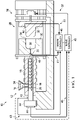
- FIG. 1 illustrates an injection molding apparatus 10 for producing molded plastic parts.
- the injection molding apparatus 10 can include an injection molding unit 12 that includes a hopper 14, a heated barrel 16, a reciprocating screw 18, and a nozzle 20.
- the reciprocating screw 18 can be disposed in the heated barrel 16 and configured to reciprocate with respect to the heated barrel 16.
- An actuation unit 22 can be operably coupled to the reciprocating screw 18 to facilitate powered reciprocation of the reciprocating screw 18.
- the actuation unit 22 can comprise a hydraulic motor.
- the actuation unit 22 can comprise an electric motor.
- an actuation unit can additionally or alternatively comprise a valve, a flow controller, an amplifier, or any of a variety of other suitable control devices for injection molding apparatuses or non-injection molding apparatuses.
- Thermoplastic pellets 24 can be placed into the hopper 14 and fed into the heated barrel 16. Once inside the heated barrel 16, the thermoplastic pellets 24 can be heated (e.g., to between about 130 degrees C to about 410 degrees C) and melted to form a molten thermoplastic material 26.
- the reciprocating screw 18 can reciprocate within the heated barrel 16 to drive the molten thermoplastic material 26 into the nozzle 20.
- the nozzle 20 can be associated with a mold 28 having first and second mold portions 30, 32 that cooperate to form a mold cavity 34.
- a clamping unit 36 can support the mold 28 and can be configured to move the first and second mold portions 30, 32 between a clamped position (not shown) and an unclamped position ( FIG. 1 ).
- molten thermoplastic material 26 from the nozzle 20 can be provided to a gate 38 defined by the first mold portion 30 and into the mold cavity 34.
- the molten thermoplastic material 26 can take the form of the mold cavity 34.
- the reciprocating screw 18 can stop, and the molten thermoplastic material 26 is permitted to cool within the mold 28.
- the first and second mold portions 30, 32 can be moved to their unclamped positions to allow the molded part to be removed from the mold 28.
- the mold 28 can include a plurality of mold cavities (e.g., 34) to increase overall production rates.
- the clamping unit 36 can apply a clamping force in the range of approximately 1000 P.S.I. to approximately 6000 P.S.I. during the molding process to hold the first and second mold portions 30, 32 together in the clamped position.
- the mold 28 in some embodiments, can be formed from a material having a surface hardness from more than about 165 BHN to less than 260 BHN, although materials having surface hardness BHN values of greater than 260 may be used as long as the material is easily machineable, as discussed further below.
- the mold 28 can be a class 101 or 102 injection mold (e.g., an "ultra-high productivity mold").
- the injection molding apparatus 10 includes a native controller 40 that is in signal communication with various components of the injection molding apparatus 10.
- the native controller 40 can be in signal communication with a screw control 44 via a signal line 45.
- the native controller 40 can command the screw control 44 to advance the reciprocating screw 18 at a rate that maintains a desired molding process, such that variations in material viscosity, mold temperatures, melt temperatures, and other variations influencing filling rate, are taken into account by the native controller 40. Adjustments may be made by the native controller 40 immediately during the molding cycle, or corrections can be made in subsequent cycles. Furthermore, several signals, from a number of cycles can be used as a basis for making adjustments to the molding process by the native controller 40.
- the native controller 40 can be any of a variety of suitable controllers for controlling the molding process.
- the native controller 40 can be a PID controller.
- the native controller 40 can be responsible for controlling a variety of different functions on the injection molding apparatus 10, such as, for example, movement of the clamping unit 36 via a signal line 37.
- the native controller 40 can be an on-board controller that is original to the injection molding unit 12 and built together with the injection molding unit 12. As such, modifications to the control architecture of the native controller 40 can be time consuming, expensive and at times impossible.
- the screw control 44 can comprise a hydraulic valve associated with the reciprocating screw 18.
- the screw control 44 can comprise an electric controller associated with the reciprocating screw 18.
- the native controller 40 can generate a signal that is transmitted from an output of the native controller 40 to the screw control 44.
- a remote controller 46 is in signal communication with the native controller 40, a melt pressure sensor 48 located in, at, or near, the nozzle 20, and with a cavity pressure sensor 50 located proximate an end of the mold cavity 34.
- the melt pressure sensor 48 can facilitate detection (direct or indirect) of the actual melt pressure (e.g., the measured melt pressure) of the molten thermoplastic material 26 at or near the nozzle 20.
- the melt pressure sensor 48 may or may not be in direct contact with the molten thermoplastic material 26.
- the melt pressure sensor 48 can be a pressure transducer that transmits an electrical signal via a signal line 49 to an input of the native controller 40 in response to the melt pressure at the nozzle 20.
- the melt pressure sensor 48 can facilitate monitoring of any of a variety of additional or alternative characteristics of the molten thermoplastic material 26 at the nozzle 20 that might indicate melt pressure, such as temperature, viscosity, and/or flow rate, for example. If the melt pressure sensor 48 is not located within the nozzle 20, the native controller 40 can be set, configured, and/or programmed with logic, commands, and/or executable program instructions to provide appropriate correction factors to estimate or calculate values for the measured characteristic in, at, or near the nozzle 20.
- sensors other than a melt pressure sensor can be employed to measure any other characteristics of the molten thermoplastic material 26, the screw 18, the barrel, or the like that is known in the art, such as, temperature, viscosity, flow rate, strain, velocity, etc. or one or more of any other characteristics that are indicative of any of these.
- the cavity pressure sensor 50 can facilitate detection (direct or indirect) of the melt pressure of the molten thermoplastic material 26 in, at, or near the nozzle 20.
- the cavity pressure sensor 50 may or may not be in direct contact with the molten thermoplastic material 26.
- the cavity pressure sensor 50 can be a pressure transducer that transmits an electrical signal via a signal line 51 to an input of the native controller 40 in response to the cavity pressure within the mold cavity 34.
- the cavity pressure sensor 50 can facilitate monitoring of any of a variety of additional or alternative characteristics of the thermoplastic material 26 or the mold 28 that might indicate cavity pressure, such as strain and/or flow rate of the molten thermoplastic material 26, for example. If the cavity pressure sensor 50 is not located within the mold cavity 34, the native controller 40 can be set, configured, and/or programmed with logic, commands, and/or executable program instructions to provide appropriate correction factors to estimate or calculate values for the measured characteristic of the mold 28.
- the remote controller 46 can sense the melt pressure and/or the cavity pressure of the injection molding apparatus 10 and can send a signal (e.g., a modified feedback signal) to the native controller 40 that affects the manner in which the native controller 40 controls the reciprocating screw 18.
- the remote controller 46 can be any of a variety of suitable controllers for providing a modified feedback signal to the native controller 40 to facilitate alternative control of the molding process.
- the remote controller 46 can be a PID controller.
- the remote controller 46 can be retrofitted onto the injection molding unit 12 to provide additional functionality not capable of being provided by the native controller 40.
- the native controller 40 Prior to retrofitting the remote controller 46 onto the injection molding apparatus 10, the native controller 40 is in signal communication with an injection pressure sensor 42 (shown in dashed lines) located at the actuation unit 22.
- the injection pressure sensor 42 can facilitate detection (direct or indirect) of the injection pressure inside of the heated barrel 16 (i.e., the pressure of the heated barrel 16 at the beginning of the reciprocating screw 18) by providing a feedback signal via a signal line 43 to the native controller 40.
- the native controller 40 can detect the injection pressure from the feedback signal and can control (e.g., feedback control) the pressures within the injection molding apparatus 10 by controlling the screw control 44, which controls the rates of injection by the injection molding unit 12.
- the output from the injection pressure sensor 42 can be disconnected from the native controller 40 and connected to the remote controller 46 thereby diverting the feedback signal from the injection pressure sensor 42 to the remote controller 46.
- the melt pressure sensor 48 and/or cavity pressure sensor 50 can then be coupled to the remote controller 46 thereby completing the retrofit.
- the native controller 40 no longer directly receives feedback signals from the injection pressure sensor 42, the melt pressure sensor 48, or the cavity pressure sensor 50. Instead, the remote controller 46 receives these feedback signals and transmits a modified feedback signal to the native controller 40 that enhances the operation of the native controller 40, as described below.
- the native controller 40 and the remote controller 46 thus operate in a closed-loop type arrangement that existed prior to addition of the remote controller 46.
- the melt pressure sensor 48 and the cavity pressure sensor 50 can already exist on the injection molding unit 12 and can be in signal communication with the native controller 40. In such an embodiment, the outputs from the melt pressure sensor 48 and the cavity pressure sensor 50 can be disconnected from the native controller 40 and reconnected to the remote controller 46. In some embodiments, the melt pressure sensor 48 and the cavity pressure sensor 50 might not already exist on the injection molding unit 12. In such an embodiment, the melt pressure sensor 48 and the cavity pressure sensor 50 can be installed during retrofitting of the remote controller 46 and then connected to the remote controller 46.
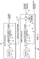
- a setpoint P2 can be provided that represents a desired melt pressure of the injection molding apparatus 10.
- a signal S4 can be provided to the remote controller 46 that indicates the actual melt pressure of the injection molding apparatus 10. The actual melt pressure can be compared against the setpoint P2 and an error signal E2 can be generated and provided to a PID control algorithm G2 that generates a control signal C2.
- a signal S5 can be provided to the remote controller 46 that indicates the measured injection pressure of the actuation unit 22.
- the control signal C2 and the signal S5 can be combined into a modified feedback signal S6.
- the modified feedback signal S6 can also include a feedforward component FF1.
- the modified feedback signal S6 can additionally or alternatively include any of a variety of other suitable control components that facilitate generation of an effective modified feedback signal.
- the modified feedback signal S6 can be transmitted to the native controller 40 in lieu of the feedback signal from the injection pressure sensor 42 (shown in dashed lines on FIG. 1 ). In one embodiment, the modified feedback signal S6 can be transmitted over a unidirectional transmission link between the native controller 40 and the remote controller 46. In such an embodiment, the native controller 40 does not transmit any signals to the remote controller 46.
- the operation of the actuation unit 22 can be controlled according to the modified feedback signal S6.
- a setpoint P1 can be provided that represents a desired injection pressure of the actuation unit 22.
- the setpoint P1 can be compared against the modified feedback signal S6 and an error signal E1 can be generated.
- the error signal E1 can be provided to a PID control algorithm G1 that generates a control signal C1 that commands the screw control 44 to advance the reciprocating screw 18 at a rate that causes the injection pressure to converge towards the desired injection pressure indicated by the setpoint P1.
- the modified feedback signal S6 from the remote controller 46 can affect the control signal C1 from the native controller 40 in a manner that actually controls the melt pressure of the injection molding apparatus 10 to the desired pressure defined by the setpoint P2 (rather than controlling the injection pressure of the actuation unit 22 to the setpoint PI).
- the remote controller 46 can thus provide the capability to control the melt pressure of the injection molding unit 12 without requiring reprograming/reconfiguration of the control architecture of the native controller 40.
- the remote controller 46 can be a cost effective and straightforward solution to add functionality to the injection molding apparatus 10 where the native controller 40 is not capable of providing such functionality independently.
- the melt pressure of the injection molding unit 12 can be changed by changing the setpoint P2.
- different setpoints can correspond to a different stage of the molding cycle.
- a setpoint can be provided that causes the melt pressure to increase enough to begin melting the thermoplastic pellets 24 and distributing the melt to the nozzle 20.
- a setpoint can be provided that initiates the filling stage at a pressure that is appropriate to properly fill the mold cavity 34.
- a setpoint can be provided to decrease enough to initiate the packing stage and hold at a substantially constant melt pressure during the holding stage.
- the native controller 40 and/or the remote controller 46 can be implemented in hardware, software or any combination of both and can have any control arrangement having one or more controllers for accomplishing control. It is to be appreciated that, although the native controller 40 is described as sensing and controlling the injection pressure of the actuation unit 22, a native controller 40 can be configured to sense and control any of a variety of suitable alternative control variables, such as, for example, a temperature of the heated barrel 16, a volume of the hopper 14, or velocity of the reciprocating screw 18.
- remote controller 46 is described as providing the capability to control the melt pressure of the injection molding unit 12
- a remote controller using the injection pressure of the actuation unit 22 can be configured to sense and control any of a variety of suitable alternative control variables, such as, for example, cavity pressure.
- remote controller 46 is described as being provided on an injection molding apparatus, a remote controller can be provided on any apparatus that employs feedback control from a native controller to add functionality to the apparatus where the native controller is not capable of providing such functionality independently.
- a remote controller can be provided on any apparatus that employs feedback control from a native controller to add functionality to the apparatus where the native controller is not capable of providing such functionality independently.
- Numerous modifications are possible in light of the above teachings. Some of those modifications have been discussed and others will be understood by those skilled in the art.
- the embodiments were chosen and described for illustration of various embodiments. The scope is, of course, not limited to the examples or embodiments set forth herein, but can be employed in any number of applications and equivalent devices by those of ordinary skill in the art.
Landscapes
- Engineering & Computer Science (AREA)
- Manufacturing & Machinery (AREA)
- Mechanical Engineering (AREA)
- Physics & Mathematics (AREA)
- General Physics & Mathematics (AREA)
- Automation & Control Theory (AREA)
- Injection Moulding Of Plastics Or The Like (AREA)
- Selective Calling Equipment (AREA)
- Feedback Control In General (AREA)
Applications Claiming Priority (2)
| Application Number | Priority Date | Filing Date | Title |
|---|---|---|---|
| US201562266996P | 2015-12-14 | 2015-12-14 | |
| PCT/US2016/065499 WO2017105981A1 (en) | 2015-12-14 | 2016-12-08 | Remote controller for controlling apparatus by diverting feedback signal from native controller to the remote controller and methods for same |
Publications (2)
| Publication Number | Publication Date |
|---|---|
| EP3389981A1 EP3389981A1 (en) | 2018-10-24 |
| EP3389981B1 true EP3389981B1 (en) | 2022-07-20 |
Family
ID=57708760
Family Applications (1)
| Application Number | Title | Priority Date | Filing Date |
|---|---|---|---|
| EP16820424.6A Active EP3389981B1 (en) | 2015-12-14 | 2016-12-08 | Remote controller for controlling apparatus by diverting feedback signal from native controller to the remote controller and methods for same |
Country Status (7)
| Country | Link |
|---|---|
| US (1) | US10281891B2 (es) |
| EP (1) | EP3389981B1 (es) |
| JP (1) | JP6964587B2 (es) |
| CN (1) | CN108430731B (es) |
| CA (1) | CA3006719C (es) |
| MX (1) | MX2018007123A (es) |
| WO (1) | WO2017105981A1 (es) |
Families Citing this family (7)
| Publication number | Priority date | Publication date | Assignee | Title |
|---|---|---|---|---|
| CA3103837A1 (en) * | 2018-06-22 | 2019-12-26 | iMFLUX Inc. | Systems and approaches for controlling an injection molding machine |
| CN112469548B (zh) | 2018-06-22 | 2023-03-14 | 艾姆弗勒克斯有限公司 | 用于控制注射模制机的系统和方法 |
| US11225006B2 (en) * | 2018-06-29 | 2022-01-18 | iMFLUX Inc. | Systems and approaches for autotuning an injection molding machine |
| MX2021002784A (es) * | 2018-09-13 | 2021-03-25 | Imflux Inc | Metodos para controlar procesos de moldeo por inyeccion con base en la presion de fusion de plastico real o la presion de cavidad. |
| EP3932647A1 (en) * | 2020-07-01 | 2022-01-05 | Actega Artística, S.A.U. | Control method and high-speed fluid injection system |
| WO2023043471A1 (en) * | 2021-09-16 | 2023-03-23 | iMFLUX Inc. | Remote controller for feedback control and methods for same |
| CN115252968A (zh) * | 2022-08-05 | 2022-11-01 | 苏州恒瑞宏远医疗科技有限公司 | 远程控制装置及注射系统 |
Family Cites Families (30)
| Publication number | Priority date | Publication date | Assignee | Title |
|---|---|---|---|---|
| US4311446A (en) * | 1974-01-21 | 1982-01-19 | Usm Corporation | Injection molding machine controls |
| US4988273A (en) * | 1989-06-23 | 1991-01-29 | Cincinnati Milacron Inc. | Injection molding machines having a brushless DC drive system |
| DE4321604A1 (de) * | 1993-06-29 | 1995-01-19 | Siemens Ag | Regeleinrichtung, insbesondere für einen nichtlinearen, zeitvarianten Prozeß |
| JP2756077B2 (ja) * | 1993-12-27 | 1998-05-25 | 東芝機械株式会社 | 射出成形機の射出成形速度条件自動設定方法 |
| US6681145B1 (en) * | 1996-06-06 | 2004-01-20 | The Boeing Company | Method for improving the accuracy of machines |
| JP3282092B2 (ja) * | 1997-06-03 | 2002-05-13 | 日精樹脂工業株式会社 | 射出成形機の射出成形方法 |
| IT1308787B1 (it) * | 1999-07-05 | 2002-01-10 | Fiat Ricerche | Sistema di controllo della propulsione per un autoveicolo. |
| JP2002120265A (ja) * | 2000-10-17 | 2002-04-23 | Toyo Mach & Metal Co Ltd | 射出成形機 |
| DE10115253A1 (de) * | 2001-03-28 | 2002-10-31 | Siemens Ag | Produktionsmaschine |
| DE102006022464B4 (de) * | 2006-05-13 | 2008-09-25 | Khs Ag | Verfahren sowie Vorrichtung zum gesteuerten Aufschäumen eines in Flaschen oder dergleichen Behälter eingebrachten Füllgutes |
| US7653460B2 (en) * | 2006-08-14 | 2010-01-26 | Husky Injection Molding Systems Ltd. | Thermal management of extruder of molding system, amongst other things |
| US8983680B2 (en) * | 2006-08-24 | 2015-03-17 | Kairos Autonmi, Inc. | Unmanned vehicle retrofitting system |
| US8610305B2 (en) * | 2006-09-18 | 2013-12-17 | Hinbit Development Ltd. | Retrofitting power distribution device and uses thereof |
| CN201520044U (zh) * | 2009-10-27 | 2010-07-07 | 武汉理工大学 | 全自动高效的注塑机控制器 |
| DE112011101682B4 (de) * | 2010-05-18 | 2016-12-08 | Mitsubishi Electric Corp. | Motorsteuervorrichtung |
| MX2013002971A (es) * | 2010-09-22 | 2013-07-29 | B9 Plasma Inc | Sistema de reactor quimico y metodos para crear puntos calientes de plasma en un medio bombeado. |
| US9205587B2 (en) * | 2012-08-08 | 2015-12-08 | Synventive Molding Solutions, Inc. | Flow control apparatus and method |
| US20120277900A1 (en) * | 2011-04-29 | 2012-11-01 | Mold-Masters (2007) Limited | Injection molding assembly having processing circuit |
| CA2835961C (en) * | 2011-05-20 | 2016-07-12 | The Procter & Gamble Company | Method and apparatus for substantially constant pressure injection molding of thinwall parts |
| JP5731933B2 (ja) * | 2011-08-30 | 2015-06-10 | 川崎重工業株式会社 | 適応制御装置および適応制御方法ならびに射出成形機の制御装置および制御方法 |
| CN102632599B (zh) * | 2012-03-27 | 2015-09-30 | 宁波恩瑞德机电科技有限公司 | 一种注塑机的控制系统 |
| US9387616B2 (en) * | 2012-08-03 | 2016-07-12 | Otto Männer Innovation GmbH | Hot runner injection molding apparatus with additional controller |
| EP3027382B1 (en) * | 2013-08-01 | 2019-04-24 | Imflux Inc. | Injection molding machines and methods for accounting for changes in material properties during injection molding runs |
| US8980146B2 (en) * | 2013-08-01 | 2015-03-17 | Imflux, Inc. | Injection molding machines and methods for accounting for changes in material properties during injection molding runs |
| JP2015090535A (ja) * | 2013-11-05 | 2015-05-11 | 服部 修 | 樹脂成形工程監視無線ネットワークシステム |
| JP6032232B2 (ja) * | 2014-03-14 | 2016-11-24 | 横河電機株式会社 | 測定装置 |
| CN107107429B (zh) * | 2014-09-22 | 2019-12-13 | 艾姆弗勒克斯有限公司 | 在减小的压力的情况下使用改装的注射成型机的方法 |
| US20160158985A1 (en) * | 2014-12-04 | 2016-06-09 | Extrude To Fill, LLC | Control system for injection molding |
| CN204773445U (zh) * | 2015-07-20 | 2015-11-18 | 中山市立义塑料五金有限公司 | 一种内置无线wifi收发端口的注塑机伺服控制系统 |
| US20170057148A1 (en) * | 2015-08-27 | 2017-03-02 | Imflux Inc | Plastic article forming apparatuses and methods for controlling melt flow |
-
2016
- 2016-12-08 CA CA3006719A patent/CA3006719C/en active Active
- 2016-12-08 MX MX2018007123A patent/MX2018007123A/es unknown
- 2016-12-08 WO PCT/US2016/065499 patent/WO2017105981A1/en active Application Filing
- 2016-12-08 EP EP16820424.6A patent/EP3389981B1/en active Active
- 2016-12-08 CN CN201680071355.7A patent/CN108430731B/zh active Active
- 2016-12-08 JP JP2018530531A patent/JP6964587B2/ja active Active
- 2016-12-14 US US15/378,932 patent/US10281891B2/en active Active
Also Published As
| Publication number | Publication date |
|---|---|
| EP3389981A1 (en) | 2018-10-24 |
| WO2017105981A1 (en) | 2017-06-22 |
| JP2019504397A (ja) | 2019-02-14 |
| US20170168471A1 (en) | 2017-06-15 |
| CA3006719C (en) | 2020-03-31 |
| CA3006719A1 (en) | 2017-06-22 |
| JP6964587B2 (ja) | 2021-11-10 |
| CN108430731A (zh) | 2018-08-21 |
| CN108430731B (zh) | 2021-05-25 |
| US10281891B2 (en) | 2019-05-07 |
| MX2018007123A (es) | 2019-01-30 |
Similar Documents
| Publication | Publication Date | Title |
|---|---|---|
| EP3389981B1 (en) | Remote controller for controlling apparatus by diverting feedback signal from native controller to the remote controller and methods for same | |
| US10994461B2 (en) | Remote controller for controlling apparatus by diverting feedback signal from native controller to the remote controller and methods for same | |
| EP3341177B1 (en) | Injection molding apparatus and method of controlling same | |
| US11135754B2 (en) | Remote controller for controlling apparatus by diverting feedback signal from native controller to the remote controller and methods for same | |
| US20230031650A1 (en) | Systems and Approaches for Controlling an Injection Molding Machine | |
| WO2023043471A1 (en) | Remote controller for feedback control and methods for same | |
| TW201811534A (zh) | 注射模製設備及其控制方法 |
Legal Events
| Date | Code | Title | Description |
|---|---|---|---|
| STAA | Information on the status of an ep patent application or granted ep patent |
Free format text: STATUS: UNKNOWN |
|
| STAA | Information on the status of an ep patent application or granted ep patent |
Free format text: STATUS: THE INTERNATIONAL PUBLICATION HAS BEEN MADE |
|
| PUAI | Public reference made under article 153(3) epc to a published international application that has entered the european phase |
Free format text: ORIGINAL CODE: 0009012 |
|
| STAA | Information on the status of an ep patent application or granted ep patent |
Free format text: STATUS: REQUEST FOR EXAMINATION WAS MADE |
|
| 17P | Request for examination filed |
Effective date: 20180705 |
|
| AK | Designated contracting states |
Kind code of ref document: A1 Designated state(s): AL AT BE BG CH CY CZ DE DK EE ES FI FR GB GR HR HU IE IS IT LI LT LU LV MC MK MT NL NO PL PT RO RS SE SI SK SM TR |
|
| AX | Request for extension of the european patent |
Extension state: BA ME |
|
| DAV | Request for validation of the european patent (deleted) | ||
| DAX | Request for extension of the european patent (deleted) | ||
| STAA | Information on the status of an ep patent application or granted ep patent |
Free format text: STATUS: EXAMINATION IS IN PROGRESS |
|
| STAA | Information on the status of an ep patent application or granted ep patent |
Free format text: STATUS: EXAMINATION IS IN PROGRESS |
|
| 17Q | First examination report despatched |
Effective date: 20201016 |
|
| STAA | Information on the status of an ep patent application or granted ep patent |
Free format text: STATUS: EXAMINATION IS IN PROGRESS |
|
| GRAP | Despatch of communication of intention to grant a patent |
Free format text: ORIGINAL CODE: EPIDOSNIGR1 |
|
| STAA | Information on the status of an ep patent application or granted ep patent |
Free format text: STATUS: GRANT OF PATENT IS INTENDED |
|
| INTG | Intention to grant announced |
Effective date: 20220301 |
|
| GRAS | Grant fee paid |
Free format text: ORIGINAL CODE: EPIDOSNIGR3 |
|
| GRAA | (expected) grant |
Free format text: ORIGINAL CODE: 0009210 |
|
| STAA | Information on the status of an ep patent application or granted ep patent |
Free format text: STATUS: THE PATENT HAS BEEN GRANTED |
|
| AK | Designated contracting states |
Kind code of ref document: B1 Designated state(s): AL AT BE BG CH CY CZ DE DK EE ES FI FR GB GR HR HU IE IS IT LI LT LU LV MC MK MT NL NO PL PT RO RS SE SI SK SM TR |
|
| REG | Reference to a national code |
Ref country code: CH Ref legal event code: EP |
|
| REG | Reference to a national code |
Ref country code: DE Ref legal event code: R096 Ref document number: 602016073668 Country of ref document: DE |
|
| REG | Reference to a national code |
Ref country code: AT Ref legal event code: REF Ref document number: 1505264 Country of ref document: AT Kind code of ref document: T Effective date: 20220815 |
|
| REG | Reference to a national code |
Ref country code: IE Ref legal event code: FG4D |
|
| REG | Reference to a national code |
Ref country code: LT Ref legal event code: MG9D |
|
| REG | Reference to a national code |
Ref country code: NL Ref legal event code: MP Effective date: 20220720 |
|
| PGFP | Annual fee paid to national office [announced via postgrant information from national office to epo] |
Ref country code: FR Payment date: 20221010 Year of fee payment: 7 |
|
| PG25 | Lapsed in a contracting state [announced via postgrant information from national office to epo] |
Ref country code: SE Free format text: LAPSE BECAUSE OF FAILURE TO SUBMIT A TRANSLATION OF THE DESCRIPTION OR TO PAY THE FEE WITHIN THE PRESCRIBED TIME-LIMIT Effective date: 20220720 Ref country code: RS Free format text: LAPSE BECAUSE OF FAILURE TO SUBMIT A TRANSLATION OF THE DESCRIPTION OR TO PAY THE FEE WITHIN THE PRESCRIBED TIME-LIMIT Effective date: 20220720 Ref country code: PT Free format text: LAPSE BECAUSE OF FAILURE TO SUBMIT A TRANSLATION OF THE DESCRIPTION OR TO PAY THE FEE WITHIN THE PRESCRIBED TIME-LIMIT Effective date: 20221121 Ref country code: NO Free format text: LAPSE BECAUSE OF FAILURE TO SUBMIT A TRANSLATION OF THE DESCRIPTION OR TO PAY THE FEE WITHIN THE PRESCRIBED TIME-LIMIT Effective date: 20221020 Ref country code: NL Free format text: LAPSE BECAUSE OF FAILURE TO SUBMIT A TRANSLATION OF THE DESCRIPTION OR TO PAY THE FEE WITHIN THE PRESCRIBED TIME-LIMIT Effective date: 20220720 Ref country code: LV Free format text: LAPSE BECAUSE OF FAILURE TO SUBMIT A TRANSLATION OF THE DESCRIPTION OR TO PAY THE FEE WITHIN THE PRESCRIBED TIME-LIMIT Effective date: 20220720 Ref country code: LT Free format text: LAPSE BECAUSE OF FAILURE TO SUBMIT A TRANSLATION OF THE DESCRIPTION OR TO PAY THE FEE WITHIN THE PRESCRIBED TIME-LIMIT Effective date: 20220720 Ref country code: FI Free format text: LAPSE BECAUSE OF FAILURE TO SUBMIT A TRANSLATION OF THE DESCRIPTION OR TO PAY THE FEE WITHIN THE PRESCRIBED TIME-LIMIT Effective date: 20220720 Ref country code: ES Free format text: LAPSE BECAUSE OF FAILURE TO SUBMIT A TRANSLATION OF THE DESCRIPTION OR TO PAY THE FEE WITHIN THE PRESCRIBED TIME-LIMIT Effective date: 20220720 |
|
| PGFP | Annual fee paid to national office [announced via postgrant information from national office to epo] |
Ref country code: GB Payment date: 20221020 Year of fee payment: 7 |
|
| REG | Reference to a national code |
Ref country code: AT Ref legal event code: MK05 Ref document number: 1505264 Country of ref document: AT Kind code of ref document: T Effective date: 20220720 |
|
| PG25 | Lapsed in a contracting state [announced via postgrant information from national office to epo] |
Ref country code: PL Free format text: LAPSE BECAUSE OF FAILURE TO SUBMIT A TRANSLATION OF THE DESCRIPTION OR TO PAY THE FEE WITHIN THE PRESCRIBED TIME-LIMIT Effective date: 20220720 Ref country code: IS Free format text: LAPSE BECAUSE OF FAILURE TO SUBMIT A TRANSLATION OF THE DESCRIPTION OR TO PAY THE FEE WITHIN THE PRESCRIBED TIME-LIMIT Effective date: 20221120 Ref country code: HR Free format text: LAPSE BECAUSE OF FAILURE TO SUBMIT A TRANSLATION OF THE DESCRIPTION OR TO PAY THE FEE WITHIN THE PRESCRIBED TIME-LIMIT Effective date: 20220720 Ref country code: GR Free format text: LAPSE BECAUSE OF FAILURE TO SUBMIT A TRANSLATION OF THE DESCRIPTION OR TO PAY THE FEE WITHIN THE PRESCRIBED TIME-LIMIT Effective date: 20221021 |
|
| REG | Reference to a national code |
Ref country code: DE Ref legal event code: R097 Ref document number: 602016073668 Country of ref document: DE |
|
| PG25 | Lapsed in a contracting state [announced via postgrant information from national office to epo] |
Ref country code: SM Free format text: LAPSE BECAUSE OF FAILURE TO SUBMIT A TRANSLATION OF THE DESCRIPTION OR TO PAY THE FEE WITHIN THE PRESCRIBED TIME-LIMIT Effective date: 20220720 Ref country code: RO Free format text: LAPSE BECAUSE OF FAILURE TO SUBMIT A TRANSLATION OF THE DESCRIPTION OR TO PAY THE FEE WITHIN THE PRESCRIBED TIME-LIMIT Effective date: 20220720 Ref country code: DK Free format text: LAPSE BECAUSE OF FAILURE TO SUBMIT A TRANSLATION OF THE DESCRIPTION OR TO PAY THE FEE WITHIN THE PRESCRIBED TIME-LIMIT Effective date: 20220720 Ref country code: CZ Free format text: LAPSE BECAUSE OF FAILURE TO SUBMIT A TRANSLATION OF THE DESCRIPTION OR TO PAY THE FEE WITHIN THE PRESCRIBED TIME-LIMIT Effective date: 20220720 Ref country code: AT Free format text: LAPSE BECAUSE OF FAILURE TO SUBMIT A TRANSLATION OF THE DESCRIPTION OR TO PAY THE FEE WITHIN THE PRESCRIBED TIME-LIMIT Effective date: 20220720 |
|
| PLBE | No opposition filed within time limit |
Free format text: ORIGINAL CODE: 0009261 |
|
| STAA | Information on the status of an ep patent application or granted ep patent |
Free format text: STATUS: NO OPPOSITION FILED WITHIN TIME LIMIT |
|
| PG25 | Lapsed in a contracting state [announced via postgrant information from national office to epo] |
Ref country code: SK Free format text: LAPSE BECAUSE OF FAILURE TO SUBMIT A TRANSLATION OF THE DESCRIPTION OR TO PAY THE FEE WITHIN THE PRESCRIBED TIME-LIMIT Effective date: 20220720 Ref country code: EE Free format text: LAPSE BECAUSE OF FAILURE TO SUBMIT A TRANSLATION OF THE DESCRIPTION OR TO PAY THE FEE WITHIN THE PRESCRIBED TIME-LIMIT Effective date: 20220720 |
|
| 26N | No opposition filed |
Effective date: 20230421 |
|
| PG25 | Lapsed in a contracting state [announced via postgrant information from national office to epo] |
Ref country code: AL Free format text: LAPSE BECAUSE OF FAILURE TO SUBMIT A TRANSLATION OF THE DESCRIPTION OR TO PAY THE FEE WITHIN THE PRESCRIBED TIME-LIMIT Effective date: 20220720 |
|
| REG | Reference to a national code |
Ref country code: CH Ref legal event code: PL |
|
| REG | Reference to a national code |
Ref country code: BE Ref legal event code: MM Effective date: 20221231 |
|
| PG25 | Lapsed in a contracting state [announced via postgrant information from national office to epo] |
Ref country code: SI Free format text: LAPSE BECAUSE OF FAILURE TO SUBMIT A TRANSLATION OF THE DESCRIPTION OR TO PAY THE FEE WITHIN THE PRESCRIBED TIME-LIMIT Effective date: 20220720 Ref country code: LU Free format text: LAPSE BECAUSE OF NON-PAYMENT OF DUE FEES Effective date: 20221208 |
|
| PG25 | Lapsed in a contracting state [announced via postgrant information from national office to epo] |
Ref country code: LI Free format text: LAPSE BECAUSE OF NON-PAYMENT OF DUE FEES Effective date: 20221231 Ref country code: IE Free format text: LAPSE BECAUSE OF NON-PAYMENT OF DUE FEES Effective date: 20221208 Ref country code: CH Free format text: LAPSE BECAUSE OF NON-PAYMENT OF DUE FEES Effective date: 20221231 |
|
| PG25 | Lapsed in a contracting state [announced via postgrant information from national office to epo] |
Ref country code: BE Free format text: LAPSE BECAUSE OF NON-PAYMENT OF DUE FEES Effective date: 20221231 |
|
| PGFP | Annual fee paid to national office [announced via postgrant information from national office to epo] |
Ref country code: DE Payment date: 20231107 Year of fee payment: 8 |
|
| PG25 | Lapsed in a contracting state [announced via postgrant information from national office to epo] |
Ref country code: HU Free format text: LAPSE BECAUSE OF FAILURE TO SUBMIT A TRANSLATION OF THE DESCRIPTION OR TO PAY THE FEE WITHIN THE PRESCRIBED TIME-LIMIT; INVALID AB INITIO Effective date: 20161208 |
|
| PG25 | Lapsed in a contracting state [announced via postgrant information from national office to epo] |
Ref country code: CY Free format text: LAPSE BECAUSE OF FAILURE TO SUBMIT A TRANSLATION OF THE DESCRIPTION OR TO PAY THE FEE WITHIN THE PRESCRIBED TIME-LIMIT Effective date: 20220720 |
|
| PG25 | Lapsed in a contracting state [announced via postgrant information from national office to epo] |
Ref country code: MK Free format text: LAPSE BECAUSE OF FAILURE TO SUBMIT A TRANSLATION OF THE DESCRIPTION OR TO PAY THE FEE WITHIN THE PRESCRIBED TIME-LIMIT Effective date: 20220720 Ref country code: IT Free format text: LAPSE BECAUSE OF FAILURE TO SUBMIT A TRANSLATION OF THE DESCRIPTION OR TO PAY THE FEE WITHIN THE PRESCRIBED TIME-LIMIT Effective date: 20220720 |
|
| PG25 | Lapsed in a contracting state [announced via postgrant information from national office to epo] |
Ref country code: MC Free format text: LAPSE BECAUSE OF FAILURE TO SUBMIT A TRANSLATION OF THE DESCRIPTION OR TO PAY THE FEE WITHIN THE PRESCRIBED TIME-LIMIT Effective date: 20220720 |
|
| PG25 | Lapsed in a contracting state [announced via postgrant information from national office to epo] |
Ref country code: MC Free format text: LAPSE BECAUSE OF FAILURE TO SUBMIT A TRANSLATION OF THE DESCRIPTION OR TO PAY THE FEE WITHIN THE PRESCRIBED TIME-LIMIT Effective date: 20220720 |
|
| PG25 | Lapsed in a contracting state [announced via postgrant information from national office to epo] |
Ref country code: BG Free format text: LAPSE BECAUSE OF FAILURE TO SUBMIT A TRANSLATION OF THE DESCRIPTION OR TO PAY THE FEE WITHIN THE PRESCRIBED TIME-LIMIT Effective date: 20220720 |
|
| GBPC | Gb: european patent ceased through non-payment of renewal fee |
Effective date: 20231208 |