EP3389878B1 - Akustische linse für eine ultraschallanordnung - Google Patents
Akustische linse für eine ultraschallanordnung Download PDFInfo
- Publication number
- EP3389878B1 EP3389878B1 EP16810411.5A EP16810411A EP3389878B1 EP 3389878 B1 EP3389878 B1 EP 3389878B1 EP 16810411 A EP16810411 A EP 16810411A EP 3389878 B1 EP3389878 B1 EP 3389878B1
- Authority
- EP
- European Patent Office
- Prior art keywords
- layer
- acoustic
- elastomer
- acoustic lens
- lens
- Prior art date
- Legal status (The legal status is an assumption and is not a legal conclusion. Google has not performed a legal analysis and makes no representation as to the accuracy of the status listed.)
- Active
Links
- 238000002604 ultrasonography Methods 0.000 title claims description 64
- 239000000463 material Substances 0.000 claims description 62
- 239000002245 particle Substances 0.000 claims description 51
- 229920001971 elastomer Polymers 0.000 claims description 50
- 239000000806 elastomer Substances 0.000 claims description 48
- 229920000306 polymethylpentene Polymers 0.000 claims description 42
- 239000011116 polymethylpentene Substances 0.000 claims description 42
- 239000005062 Polybutadiene Substances 0.000 claims description 41
- 229920002857 polybutadiene Polymers 0.000 claims description 41
- 229920001169 thermoplastic Polymers 0.000 claims description 21
- 229920001577 copolymer Polymers 0.000 claims description 19
- 239000000523 sample Substances 0.000 claims description 19
- 229920001187 thermosetting polymer Polymers 0.000 claims description 17
- MCMNRKCIXSYSNV-UHFFFAOYSA-N ZrO2 Inorganic materials O=[Zr]=O MCMNRKCIXSYSNV-UHFFFAOYSA-N 0.000 claims description 13
- RVTZCBVAJQQJTK-UHFFFAOYSA-N oxygen(2-);zirconium(4+) Chemical compound [O-2].[O-2].[Zr+4] RVTZCBVAJQQJTK-UHFFFAOYSA-N 0.000 claims description 13
- 229920000098 polyolefin Polymers 0.000 claims description 11
- 229930195733 hydrocarbon Natural products 0.000 claims description 10
- 150000002430 hydrocarbons Chemical class 0.000 claims description 10
- 239000000919 ceramic Substances 0.000 claims description 9
- 239000000178 monomer Substances 0.000 claims description 9
- 239000004215 Carbon black (E152) Substances 0.000 claims description 7
- 239000004711 α-olefin Substances 0.000 claims description 6
- VGGSQFUCUMXWEO-UHFFFAOYSA-N Ethene Chemical compound C=C VGGSQFUCUMXWEO-UHFFFAOYSA-N 0.000 claims description 4
- 239000005977 Ethylene Substances 0.000 claims description 4
- 229920002725 thermoplastic elastomer Polymers 0.000 claims description 2
- 239000010410 layer Substances 0.000 description 183
- 239000000203 mixture Substances 0.000 description 67
- 239000012528 membrane Substances 0.000 description 33
- 229920006124 polyolefin elastomer Polymers 0.000 description 33
- 210000004027 cell Anatomy 0.000 description 30
- 239000007788 liquid Substances 0.000 description 15
- 229920000642 polymer Polymers 0.000 description 11
- 230000002829 reductive effect Effects 0.000 description 11
- 238000012285 ultrasound imaging Methods 0.000 description 10
- 229920002379 silicone rubber Polymers 0.000 description 9
- 241000907903 Shorea Species 0.000 description 8
- 230000008878 coupling Effects 0.000 description 8
- 238000010168 coupling process Methods 0.000 description 8
- 238000005859 coupling reaction Methods 0.000 description 8
- 239000000126 substance Substances 0.000 description 8
- 229920002397 thermoplastic olefin Polymers 0.000 description 8
- 210000001519 tissue Anatomy 0.000 description 8
- 150000001336 alkenes Chemical class 0.000 description 7
- 230000005540 biological transmission Effects 0.000 description 7
- 238000006073 displacement reaction Methods 0.000 description 7
- 239000000945 filler Substances 0.000 description 7
- 238000004519 manufacturing process Methods 0.000 description 7
- XUIMIQQOPSSXEZ-UHFFFAOYSA-N Silicon Chemical compound [Si] XUIMIQQOPSSXEZ-UHFFFAOYSA-N 0.000 description 6
- 230000008901 benefit Effects 0.000 description 6
- 238000002156 mixing Methods 0.000 description 6
- 239000010703 silicon Substances 0.000 description 6
- 229910052710 silicon Inorganic materials 0.000 description 6
- 239000000758 substrate Substances 0.000 description 6
- 238000000034 method Methods 0.000 description 5
- JRZJOMJEPLMPRA-UHFFFAOYSA-N olefin Natural products CCCCCCCC=C JRZJOMJEPLMPRA-UHFFFAOYSA-N 0.000 description 5
- 230000001902 propagating effect Effects 0.000 description 5
- 239000002904 solvent Substances 0.000 description 5
- IMNFDUFMRHMDMM-UHFFFAOYSA-N N-Heptane Chemical compound CCCCCCC IMNFDUFMRHMDMM-UHFFFAOYSA-N 0.000 description 4
- 238000004458 analytical method Methods 0.000 description 4
- 238000003491 array Methods 0.000 description 4
- 238000004132 cross linking Methods 0.000 description 4
- 235000014113 dietary fatty acids Nutrition 0.000 description 4
- 238000009826 distribution Methods 0.000 description 4
- 238000005516 engineering process Methods 0.000 description 4
- 229930195729 fatty acid Natural products 0.000 description 4
- 239000000194 fatty acid Substances 0.000 description 4
- 150000004665 fatty acids Chemical class 0.000 description 4
- 238000002844 melting Methods 0.000 description 4
- 230000008018 melting Effects 0.000 description 4
- 230000009467 reduction Effects 0.000 description 4
- 239000004416 thermosoftening plastic Substances 0.000 description 4
- 230000009286 beneficial effect Effects 0.000 description 3
- 230000008859 change Effects 0.000 description 3
- 239000000645 desinfectant Substances 0.000 description 3
- 239000006185 dispersion Substances 0.000 description 3
- 230000009477 glass transition Effects 0.000 description 3
- 238000003384 imaging method Methods 0.000 description 3
- 230000007246 mechanism Effects 0.000 description 3
- VLKZOEOYAKHREP-UHFFFAOYSA-N n-Hexane Chemical compound CCCCCC VLKZOEOYAKHREP-UHFFFAOYSA-N 0.000 description 3
- RRHGJUQNOFWUDK-UHFFFAOYSA-N Isoprene Chemical compound CC(=C)C=C RRHGJUQNOFWUDK-UHFFFAOYSA-N 0.000 description 2
- 229910052581 Si3N4 Inorganic materials 0.000 description 2
- VYPSYNLAJGMNEJ-UHFFFAOYSA-N Silicium dioxide Chemical compound O=[Si]=O VYPSYNLAJGMNEJ-UHFFFAOYSA-N 0.000 description 2
- GWEVSGVZZGPLCZ-UHFFFAOYSA-N Titan oxide Chemical compound O=[Ti]=O GWEVSGVZZGPLCZ-UHFFFAOYSA-N 0.000 description 2
- PNEYBMLMFCGWSK-UHFFFAOYSA-N aluminium oxide Inorganic materials [O-2].[O-2].[O-2].[Al+3].[Al+3] PNEYBMLMFCGWSK-UHFFFAOYSA-N 0.000 description 2
- TZCXTZWJZNENPQ-UHFFFAOYSA-L barium sulfate Chemical compound [Ba+2].[O-]S([O-])(=O)=O TZCXTZWJZNENPQ-UHFFFAOYSA-L 0.000 description 2
- WMWLMWRWZQELOS-UHFFFAOYSA-N bismuth(iii) oxide Chemical compound O=[Bi]O[Bi]=O WMWLMWRWZQELOS-UHFFFAOYSA-N 0.000 description 2
- 229910052799 carbon Inorganic materials 0.000 description 2
- 239000003795 chemical substances by application Substances 0.000 description 2
- 238000001938 differential scanning calorimetry curve Methods 0.000 description 2
- 238000007598 dipping method Methods 0.000 description 2
- 238000001035 drying Methods 0.000 description 2
- 229920005621 immiscible polymer blend Polymers 0.000 description 2
- 230000033001 locomotion Effects 0.000 description 2
- 238000005457 optimization Methods 0.000 description 2
- 229920001296 polysiloxane Polymers 0.000 description 2
- 239000005060 rubber Substances 0.000 description 2
- 239000004065 semiconductor Substances 0.000 description 2
- HQVNEWCFYHHQES-UHFFFAOYSA-N silicon nitride Chemical compound N12[Si]34N5[Si]62N3[Si]51N64 HQVNEWCFYHHQES-UHFFFAOYSA-N 0.000 description 2
- 229910052814 silicon oxide Inorganic materials 0.000 description 2
- 230000007704 transition Effects 0.000 description 2
- XLYOFNOQVPJJNP-UHFFFAOYSA-N water Substances O XLYOFNOQVPJJNP-UHFFFAOYSA-N 0.000 description 2
- WRIDQFICGBMAFQ-UHFFFAOYSA-N (E)-8-Octadecenoic acid Natural products CCCCCCCCCC=CCCCCCCC(O)=O WRIDQFICGBMAFQ-UHFFFAOYSA-N 0.000 description 1
- LQJBNNIYVWPHFW-UHFFFAOYSA-N 20:1omega9c fatty acid Natural products CCCCCCCCCCC=CCCCCCCCC(O)=O LQJBNNIYVWPHFW-UHFFFAOYSA-N 0.000 description 1
- WSSSPWUEQFSQQG-UHFFFAOYSA-N 4-methyl-1-pentene Chemical compound CC(C)CC=C WSSSPWUEQFSQQG-UHFFFAOYSA-N 0.000 description 1
- QSBYPNXLFMSGKH-UHFFFAOYSA-N 9-Heptadecensaeure Natural products CCCCCCCC=CCCCCCCCC(O)=O QSBYPNXLFMSGKH-UHFFFAOYSA-N 0.000 description 1
- XDTMQSROBMDMFD-UHFFFAOYSA-N Cyclohexane Chemical compound C1CCCCC1 XDTMQSROBMDMFD-UHFFFAOYSA-N 0.000 description 1
- UFHFLCQGNIYNRP-UHFFFAOYSA-N Hydrogen Chemical compound [H][H] UFHFLCQGNIYNRP-UHFFFAOYSA-N 0.000 description 1
- VQTUBCCKSQIDNK-UHFFFAOYSA-N Isobutene Chemical group CC(C)=C VQTUBCCKSQIDNK-UHFFFAOYSA-N 0.000 description 1
- OYHQOLUKZRVURQ-HZJYTTRNSA-N Linoleic acid Chemical compound CCCCC\C=C/C\C=C/CCCCCCCC(O)=O OYHQOLUKZRVURQ-HZJYTTRNSA-N 0.000 description 1
- 241001465754 Metazoa Species 0.000 description 1
- 239000005642 Oleic acid Substances 0.000 description 1
- ZQPPMHVWECSIRJ-UHFFFAOYSA-N Oleic acid Natural products CCCCCCCCC=CCCCCCCCC(O)=O ZQPPMHVWECSIRJ-UHFFFAOYSA-N 0.000 description 1
- 239000004698 Polyethylene Substances 0.000 description 1
- 238000009825 accumulation Methods 0.000 description 1
- 239000012814 acoustic material Substances 0.000 description 1
- 150000001335 aliphatic alkanes Chemical class 0.000 description 1
- 125000001931 aliphatic group Chemical group 0.000 description 1
- DTOSIQBPPRVQHS-PDBXOOCHSA-N alpha-linolenic acid Chemical compound CC\C=C/C\C=C/C\C=C/CCCCCCCC(O)=O DTOSIQBPPRVQHS-PDBXOOCHSA-N 0.000 description 1
- 235000020661 alpha-linolenic acid Nutrition 0.000 description 1
- 239000004411 aluminium Substances 0.000 description 1
- XAGFODPZIPBFFR-UHFFFAOYSA-N aluminium Chemical compound [Al] XAGFODPZIPBFFR-UHFFFAOYSA-N 0.000 description 1
- 230000015572 biosynthetic process Effects 0.000 description 1
- WXCZUWHSJWOTRV-UHFFFAOYSA-N but-1-ene;ethene Chemical compound C=C.CCC=C WXCZUWHSJWOTRV-UHFFFAOYSA-N 0.000 description 1
- 239000001273 butane Substances 0.000 description 1
- 229920005549 butyl rubber Polymers 0.000 description 1
- 125000004432 carbon atom Chemical group C* 0.000 description 1
- 239000011203 carbon fibre reinforced carbon Substances 0.000 description 1
- 150000001735 carboxylic acids Chemical class 0.000 description 1
- 210000000170 cell membrane Anatomy 0.000 description 1
- 239000002131 composite material Substances 0.000 description 1
- 238000013329 compounding Methods 0.000 description 1
- 239000004020 conductor Substances 0.000 description 1
- 229910052593 corundum Inorganic materials 0.000 description 1
- 150000001924 cycloalkanes Chemical class 0.000 description 1
- 230000003247 decreasing effect Effects 0.000 description 1
- 230000001419 dependent effect Effects 0.000 description 1
- 238000000113 differential scanning calorimetry Methods 0.000 description 1
- 230000000694 effects Effects 0.000 description 1
- 238000001704 evaporation Methods 0.000 description 1
- 230000001747 exhibiting effect Effects 0.000 description 1
- 238000001595 flow curve Methods 0.000 description 1
- 239000007789 gas Substances 0.000 description 1
- 239000003292 glue Substances 0.000 description 1
- 239000008187 granular material Substances 0.000 description 1
- 229910000449 hafnium oxide Inorganic materials 0.000 description 1
- WIHZLLGSGQNAGK-UHFFFAOYSA-N hafnium(4+);oxygen(2-) Chemical compound [O-2].[O-2].[Hf+4] WIHZLLGSGQNAGK-UHFFFAOYSA-N 0.000 description 1
- 238000010438 heat treatment Methods 0.000 description 1
- 239000001257 hydrogen Substances 0.000 description 1
- 229910052739 hydrogen Inorganic materials 0.000 description 1
- 230000006872 improvement Effects 0.000 description 1
- 230000036512 infertility Effects 0.000 description 1
- 239000011810 insulating material Substances 0.000 description 1
- 238000009413 insulation Methods 0.000 description 1
- 230000003993 interaction Effects 0.000 description 1
- 230000002427 irreversible effect Effects 0.000 description 1
- QXJSBBXBKPUZAA-UHFFFAOYSA-N isooleic acid Natural products CCCCCCCC=CCCCCCCCCC(O)=O QXJSBBXBKPUZAA-UHFFFAOYSA-N 0.000 description 1
- 229920001580 isotactic polymer Polymers 0.000 description 1
- 230000000670 limiting effect Effects 0.000 description 1
- 235000020778 linoleic acid Nutrition 0.000 description 1
- OYHQOLUKZRVURQ-IXWMQOLASA-N linoleic acid Natural products CCCCC\C=C/C\C=C\CCCCCCCC(O)=O OYHQOLUKZRVURQ-IXWMQOLASA-N 0.000 description 1
- 229960004488 linolenic acid Drugs 0.000 description 1
- KQQKGWQCNNTQJW-UHFFFAOYSA-N linolenic acid Natural products CC=CCCC=CCC=CCCCCCCCC(O)=O KQQKGWQCNNTQJW-UHFFFAOYSA-N 0.000 description 1
- 229910052751 metal Inorganic materials 0.000 description 1
- 239000002184 metal Substances 0.000 description 1
- 229910044991 metal oxide Inorganic materials 0.000 description 1
- 150000004706 metal oxides Chemical class 0.000 description 1
- 238000000465 moulding Methods 0.000 description 1
- IJDNQMDRQITEOD-UHFFFAOYSA-N n-butane Chemical compound CCCC IJDNQMDRQITEOD-UHFFFAOYSA-N 0.000 description 1
- OFBQJSOFQDEBGM-UHFFFAOYSA-N n-pentane Natural products CCCCC OFBQJSOFQDEBGM-UHFFFAOYSA-N 0.000 description 1
- TVMXDCGIABBOFY-UHFFFAOYSA-N octane Chemical compound CCCCCCCC TVMXDCGIABBOFY-UHFFFAOYSA-N 0.000 description 1
- ZQPPMHVWECSIRJ-KTKRTIGZSA-N oleic acid Chemical compound CCCCCCCC\C=C/CCCCCCCC(O)=O ZQPPMHVWECSIRJ-KTKRTIGZSA-N 0.000 description 1
- 235000021313 oleic acid Nutrition 0.000 description 1
- 230000003287 optical effect Effects 0.000 description 1
- 150000002894 organic compounds Chemical class 0.000 description 1
- 238000013021 overheating Methods 0.000 description 1
- TWNQGVIAIRXVLR-UHFFFAOYSA-N oxo(oxoalumanyloxy)alumane Chemical compound O=[Al]O[Al]=O TWNQGVIAIRXVLR-UHFFFAOYSA-N 0.000 description 1
- 230000002093 peripheral effect Effects 0.000 description 1
- 230000000704 physical effect Effects 0.000 description 1
- 229920003023 plastic Polymers 0.000 description 1
- 239000004033 plastic Substances 0.000 description 1
- -1 polyethylene Polymers 0.000 description 1
- 229920000573 polyethylene Polymers 0.000 description 1
- 239000002861 polymer material Substances 0.000 description 1
- 239000013047 polymeric layer Substances 0.000 description 1
- 238000004321 preservation Methods 0.000 description 1
- 230000008569 process Effects 0.000 description 1
- 230000001681 protective effect Effects 0.000 description 1
- 230000002441 reversible effect Effects 0.000 description 1
- 229920006395 saturated elastomer Polymers 0.000 description 1
- 229930195734 saturated hydrocarbon Natural products 0.000 description 1
- 239000004945 silicone rubber Substances 0.000 description 1
- 238000004088 simulation Methods 0.000 description 1
- 210000004872 soft tissue Anatomy 0.000 description 1
- 239000007787 solid Substances 0.000 description 1
- 241000894007 species Species 0.000 description 1
- 239000007921 spray Substances 0.000 description 1
- 230000001954 sterilising effect Effects 0.000 description 1
- 238000004659 sterilization and disinfection Methods 0.000 description 1
- 230000009466 transformation Effects 0.000 description 1
- 229930195735 unsaturated hydrocarbon Natural products 0.000 description 1
- 229910001845 yogo sapphire Inorganic materials 0.000 description 1
Images


Classifications
-
- G—PHYSICS
- G10—MUSICAL INSTRUMENTS; ACOUSTICS
- G10K—SOUND-PRODUCING DEVICES; METHODS OR DEVICES FOR PROTECTING AGAINST, OR FOR DAMPING, NOISE OR OTHER ACOUSTIC WAVES IN GENERAL; ACOUSTICS NOT OTHERWISE PROVIDED FOR
- G10K11/00—Methods or devices for transmitting, conducting or directing sound in general; Methods or devices for protecting against, or for damping, noise or other acoustic waves in general
- G10K11/18—Methods or devices for transmitting, conducting or directing sound
- G10K11/26—Sound-focusing or directing, e.g. scanning
- G10K11/30—Sound-focusing or directing, e.g. scanning using refraction, e.g. acoustic lenses
-
- A—HUMAN NECESSITIES
- A61—MEDICAL OR VETERINARY SCIENCE; HYGIENE
- A61B—DIAGNOSIS; SURGERY; IDENTIFICATION
- A61B8/00—Diagnosis using ultrasonic, sonic or infrasonic waves
- A61B8/44—Constructional features of the ultrasonic, sonic or infrasonic diagnostic device
- A61B8/4444—Constructional features of the ultrasonic, sonic or infrasonic diagnostic device related to the probe
-
- A—HUMAN NECESSITIES
- A61—MEDICAL OR VETERINARY SCIENCE; HYGIENE
- A61B—DIAGNOSIS; SURGERY; IDENTIFICATION
- A61B8/00—Diagnosis using ultrasonic, sonic or infrasonic waves
- A61B8/44—Constructional features of the ultrasonic, sonic or infrasonic diagnostic device
- A61B8/4483—Constructional features of the ultrasonic, sonic or infrasonic diagnostic device characterised by features of the ultrasound transducer
- A61B8/4494—Constructional features of the ultrasonic, sonic or infrasonic diagnostic device characterised by features of the ultrasound transducer characterised by the arrangement of the transducer elements
-
- B—PERFORMING OPERATIONS; TRANSPORTING
- B06—GENERATING OR TRANSMITTING MECHANICAL VIBRATIONS IN GENERAL
- B06B—METHODS OR APPARATUS FOR GENERATING OR TRANSMITTING MECHANICAL VIBRATIONS OF INFRASONIC, SONIC, OR ULTRASONIC FREQUENCY, e.g. FOR PERFORMING MECHANICAL WORK IN GENERAL
- B06B1/00—Methods or apparatus for generating mechanical vibrations of infrasonic, sonic, or ultrasonic frequency
- B06B1/02—Methods or apparatus for generating mechanical vibrations of infrasonic, sonic, or ultrasonic frequency making use of electrical energy
- B06B1/0292—Electrostatic transducers, e.g. electret-type
-
- G—PHYSICS
- G01—MEASURING; TESTING
- G01N—INVESTIGATING OR ANALYSING MATERIALS BY DETERMINING THEIR CHEMICAL OR PHYSICAL PROPERTIES
- G01N29/00—Investigating or analysing materials by the use of ultrasonic, sonic or infrasonic waves; Visualisation of the interior of objects by transmitting ultrasonic or sonic waves through the object
- G01N29/22—Details, e.g. general constructional or apparatus details
- G01N29/221—Arrangements for directing or focusing the acoustical waves
-
- G—PHYSICS
- G01—MEASURING; TESTING
- G01N—INVESTIGATING OR ANALYSING MATERIALS BY DETERMINING THEIR CHEMICAL OR PHYSICAL PROPERTIES
- G01N29/00—Investigating or analysing materials by the use of ultrasonic, sonic or infrasonic waves; Visualisation of the interior of objects by transmitting ultrasonic or sonic waves through the object
- G01N29/22—Details, e.g. general constructional or apparatus details
- G01N29/24—Probes
- G01N29/2406—Electrostatic or capacitive probes, e.g. electret or cMUT-probes
Definitions
- the invention relates to an acoustic lens for an ultrasound array of capacitive micromachined transducers.
- the invention further relates an ultrasound probe comprising such an acoustic lens.
- CMUT capacitive micro-machined ultrasound transducers
- PZT piezoelectric based ultrasound transducers
- a CMUT transducer cell comprises a cavity with a movable mechanical part also called a membrane and a pair of electrodes separated by the cavity.
- ultrasound waves When receiving ultrasound waves, ultrasound waves cause the membrane to move or vibrate and change the capacitance between the electrodes which can be detected. Thereby the ultrasound waves are transformed into a corresponding electrical signal.
- an electrical signal applied to the electrodes causes the membrane to move or vibrate, thereby transmitting ultrasound waves.
- CMUTs can be made using semiconductor fabrication processes and, therefore, may be easier integrated with application-specific integrated circuitry (ASIC); CMUT transducers offer low cost, extended frequency range and finer acoustic pitch over traditional PZTs. Inherently from the PZT based technology most of the commonly used ultrasound arrays with CMUTs have acoustic windows or lens materials selected from the materials used for the PZT-based transducers, such as silicon rubbers, for example RTV.
- US 4,880,012 discloses a composite acoustic lens suitable for application with a piezoelectric (PZT) based array.
- the acoustic lens of US 4,880,012 comprises a first layer bonded to the upper surface of the acoustic matching layer being in contact with the PZT array and a second acoustic lens layer bonded to the upper bonded to the upper surface of the first layer. This acoustic lens converges ultrasound waves generated by the array by providing the second acoustic lens layer having a higher attenuation
- the first layer of the acoustic lens of US 4,880,012 is made of a silicon rubber containing no filler and showing the sound velocity of about 1000 m/s.
- the second acoustic lens layer is made of a silicone rubber containing a filler such as aluminum oxide to increase its ultrasound attenuation coefficient.
- the CMUT possesses different to the PZT mechanism of an electro-acoustical transformation, wherein an interactions between the CMUT membranes and the acoustic materials used for lens may reduce the acoustic performance of the transducer.
- traditional filled silicon rubbers also referred here as room temperature curing rubber or RTV
- RTV room temperature curing rubber
- WO2015/028325 A1 discloses an acoustic lens for an ultrasound array of capacitive micromachined transducers comprising a first layer made from polybutadiene and having an outer convex shaped surface, and an exterior layer made from polyethylene.
- EP3374095 A1 is prior art pursuant to Article 54(3) EPC and discloses an acoustic lens for an ultrasound array of capacitive micromachined transducers comprising a first layer comprising a thermoset elastomer having a polymeric material selected from a hydrocarbon family, wherein the first layer has an inner surface arranged to face the array and an outer convex shaped surface arranged to oppose the inner surface; and further comprising a second layer coupled to the outer surface of the first layer and comprising thermoplastic polymer polymethylpentene and an elastomer selected from a polyolefin family blended therein, wherein the first layer has a first acoustic wave velocity and the second layer has a second acoustic wave velocity, said second wave velocity is larger than the first wave velocity.
- the acoustic lens of the present invention advantageously combines a use of two materials suitable for providing an acoustic wave converging lens applicable with the CMUT array.
- the first layer of the thermoset elastomer has a polymeric material selected from a hydrocarbon family. This layer placed in the closed proximity to the CMUT array exhibit an acoustic loss per millimeter for acoustic energy passing therethrough of less than 2 dB for a wide range of the acoustic wave frequencies applicable in medical ultrasound, such as in between 2 and 25 MHz.
- the layer of the thermoset elastomer having a polymeric material selected from the hydrocarbons has a density equal or below 0.95 g/cm 3 and an acoustic impedance equal or above 1.45 MRayl.
- the first layer When placed in a direct contact with the CMUT cell membrane the first layer provides an improved acoustical coupling of the acoustic window layer to the membrane of the CMUT cell. Thus, no additional coupling medium between the acoustic window and the CMUT array is required.
- the second layer comprising a thermoplastic polymer polymethylpentene provides a mechanical and chemical stability of the acoustic lens.
- the first layer comprising the thermoset elastomer has a first acoustic wave velocity (v1) and the second layer comprising thermoplastic polymer has a second acoustic wave velocity (v2) larger than the first acoustic wave velocity.
- This wave velocities difference in combination with the convex shape of the outer surface of the first layer provides a convergence of the acoustic waves generated by the CMUT array at a focal point of the acoustic lens. It is beneficial to have an acoustic lens comprising layers with the lowest possible acoustic wave attenuation.
- Polymethylpentene (TPX) material used as the second layer of the acoustic lens shows one of the lowest longitudinal acoustic wave attenuation among the thermoplastic polyolefins. It shows an acoustic loss per millimeter for acoustic energy passing therethrough of less than 3.5 dB for a wide range of the acoustic wave frequencies applicable in medical ultrasound, such as 2 to 10 MHz.
- Polymethylpentene is suitable for blending with polyolefin elastomers, which have higher attenuation for for both the longitudinal acoustic wave and share wave. An introduction of the polyolefin elastomer into the blend with polymethylpentene changes the density of the blend.
- the average impedance of the second layer may be tuned with the blended elastomer therein.
- Polymethylpentene provides the blend with mechanical, chemical stability and with low acoustic wave attenuation; whilst the polyolefin elastomer provides a possibility to tune the acoustic impedance of the blend and to further improve its acoustic wave propagation properties. If the second layer exhibits a low acoustic attenuation and reduced acoustic impedance that may be closer matched to the body, human tissue (about 1.6 MRayl).
- the second layer comprising the polyolefin nature of the blend provides low water permeation levels.
- the second layer comprising this blend is resistant to disinfectants (used for typical medical ultrasound equipment); and has a good mechanical protective properties as impact and wear resistance and is bio compatible.
- the blend of polymethylpentene and polyolefin elastomer also provides an increased shear wave attenuation that beneficially reduces a cross talk between the transducer elements. Therefore, an application of such second layer may show a reduction of image artefacts during the ultrasound imaging.
- the elastomer includes polybutadiene.
- Polybutadiene shows one of the lowest attenuation effects on the propagating acoustic energy.
- Polybutadiene material also provides a large band width of about 140% at 3 dB-point for the propagating acoustic signal. The acoustical coupling of this material to the CMUT array provides an optimal preservation of mechanical properties of the vibrating (moving) part of the CMUTs and results in the optimal acoustic energy propagation.
- the first layer including polybutadiene further comprises particles embedded therein for acoustic impedance adjustment of the first layer.
- the introduction of the embedded particles into the polymeric material particles provides a possibility of increasing a total acoustic impedance of the first layer. This allows to tune the first layer's impedance closer to the acoustic layer impedance of the second layer.
- the first layer of the acoustic lens comprises polybutadiene with embedded insulating particles a direct acoustical coupling of the acoustical window layer to the membrane of the CMUT cell is provided. Thus, no additional coupling medium between the acoustic window and the CMUT array is required.
- a relatively smaller percentage by weight of the particles may need to be added for the further acoustic impedance adjustment such that the maximum acoustic impedance of the lens does not exceed a value of about 1.6 MRayl corresponding to the acoustic impedance of an ultrasonicated tissue.
- the elastomer of the second layer is a thermoplastic elastomer comprising copolymer chains.
- the outer acoustic layer of this embodiment would be a blend having thermoplastic properties.
- An example of the thermoplastic polyolefin elastomer (TPE) may be a copolymer of ethylene and another alpha olefin.
- TPE thermoplastic polyolefin elastomer
- a percentage by weight of the particles based on the total weight of the first layer relates to the percentage by weight of the elastomer based on the total weight of the second layer, such that acoustic impedance of the first layer is substantially the same as the acoustic impedance of the second layer.
- This embodiment allows a relative tuning of the acoustic impedances of the first and the second layers, while keeping the second wave velocity being larger than the first wave velocity.
- the percentages of the particles in the first layer and of the polyolefin elastomer can be selected such that the acoustic impedances of the two layers are matching (substantially the same). In this case the acoustic wave reflections at the interface of the two layers are minimized due to the matching acoustic impedance.
- the transmission properties of the acoustic lens suitable for the acoustic waves converging, are improved. It is further beneficial to have the acoustic wave impedance of the lens to be close to the tissue impedance of about 1.6 MRayl.
- the particles in the first layer include ceramic particles and the selected elastomer includes a copolymer having a first monomer being an alpha olefin and a second monomer being ethylene.
- Ceramic particles are insulating and therefore can reduce often unwanted in medical application conductivity of the first layer.
- Olefin based copolymers are suitable for blending with polymethylpentene.
- the percentage by weight of the ceramic particles based on the total weight of the first layer is at most 25% and the percentage by weight of the elastomer based on the total weight of the second layer is at most 40%.
- This embodiment provides improved conditions for the acoustic wave transition through the acoustic lens. Limiting the percentage of the particles to 25% and of the elastomer to 40%, preferably about 20%, provides a control over the wave's attenuation in the lens layers.
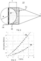
- Fig.1 shows a principle of constructing a converging acoustic lens 13.
- the lens 13 is coupled to a source of the acoustic waves - an array of the capacitive ultrasound transducers 74.
- the acoustic lens comprises a first layer 47 forming an inner layer, which is in an acoustic contact with the CMUT array, and a second layer 42 forming an outer layer of the lens.
- the first layer 47 has an inner surface arranged to face the array and outer convex shaped surface 40 arranged to oppose the inner surface of the first layer.
- the second layer coupled to the outer surface of the first layer may be forming an outer surface 71 of the acoustic lens 13.
- the outer surface is intended to face a patient 201 or a body to be examined by the ultrasound imaging system 202 (illustrated in FIG. 12 ).
- R1 is radius of curvature of the outer surface of the first layer relative to the CMUT array and R2 is radius of curvature of the second layer with respect to the CMUT array (in the present example this is the radius of the outer surface of the lens).
- the refractive index of the lens is defined by a ratio of the acoustic wave velocities in the first (v1) and the second (v2) acoustic lens layers.
- the second wave velocity is larger than the first wave velocity (v2>v1) the refraction index of the lens is greater than one.
- n v 2 v 1 > 1
- the acoustic lens coverages the acoustic waves at the focal point located at the focal distance (f) from the array.
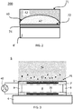
- FIG. 2 shows an ultrasound probe 200 according to the invention, comprising the CMUT array 74.
- the ultrasound array 74 has an ultrasound wave emitting side facing an inner surface 72 of an an acoustic lens 13 and a backing side opposite to the emitting side.
- the CMUT array may contain ultrasound transducers coupled to an integrated circuitry adapted to drive and control the transducers in the array.
- the backing side of the array is electrically coupled to a probe's base 4', which communicates input and output signals of the integrated circuitry to and from an ultrasound system 202 ( FIG.12 ).
- the acoustic lens 13 comprises a first layer 47 having the inner surface 72 arranged to face the CMUT array 74 and an outer convex shaped surface 40 arranged to oppose the inner surface; and a second layer 42 coupled to the outer surface 40 of the first layer 47.
- the first layer comprises a thermoset elastomer having a polymeric material selected from a hydrocarbon family.
- the thermoset elastomers are selected from hydrocarbons contain only hydrogen and carbon atoms and have a relatively low density (below 1 g/cm 3 ).
- An application of the thermoset elastomers to the emitting surface of the CMUT array showed to provide an improved acoustic wave transmission through the first layer.
- thermoset elastomers which are generally characterized by wide-meshed crosslinking of the "knotted" molecular chains. This type of crosslinking means that the materials have a high level of dimensional stability but are still elastically malleable. By applying load (for instance tensile load) the chains become stretched, but after removal of the load they relax again.
- load for instance tensile load
- a typical hardness of the uncured elastomers is below 50 ShoreA, measured by a durometer (A scale). In general, cured (baked) elastomers exhibit higher hardness than 50 ShoreA.
- the elastomer comprising layer can be either under-cured (the solvent is not entirely evaporated as described in step) or/ and have fatty acids added into a liquid mixture of the elastomer material. This will be discussed below in detail.
- thermoset elastomers are characterized by three-dimensional closely meshed irreversible crosslinking.
- Thermoset elastomers are chemically and mechanically more stable among elastomers, thermoset elastomers may be processed similar to thermoplastics.
- thermoset elastomer with different hardness can be selected.
- Uncured polybutadiene for example, has a hardness of about 50 ShoreA, while butyl rubber, which polymeric chains consist of two monomers: isobutylene and isoprene, may show hardness values as low as 40 ShoreA.
- An olefin family (also alkenes) is a family of the unsaturated hydrocarbons comprising at least one carbon-carbon double bond.
- the second layer 42 of the acoustic lens 13 comprises a polyolefin based thermoplastic polymer polmethylpentene.
- a polyolefin is a polymer comprising monomers selected from the olefin family.
- This layer further provides an efficient acoustic wave transmission through the acoustic lens by causing a reduced attenuation of the wave.
- the first layer has a first acoustic wave velocity (v1) and the second layer has a second acoustic wave velocity (v2), which is exceeds the first acoustic wave velocity, and the acoustic lens can be used for focusing the acoustic wave beams generated by the CMUT array.
- Thermoplastic polymers are polymers in which, unlike thermoset elastomers, the molecular chains are not crosslinked. They consequently demonstrate plastic elastic behavior and are thermoformable (having the property of softening or fusing when heated and of hardening again when cooled). This formability is reversible, in other words can be repeated as often as required as long as the material is not thermally damaged by overheating. Since thermoplastics have little or no cross-linking their individual polymer chains can slip past one another on heating. In thermoplastic polyolefin, compared to the saturated hydrocarbons, the polyolefin family provides the thermoplastic polymer with a relatively light molecular weight.
- the thermoplastic polyolefin comprises linear isotactic polymers. In general thermoplastic polymers have a hardness of above 60 ShoreA.
- the preferred material used in the lens for the first layer is polybutadiene.
- Polybutadiene and polymethylpentene (TPX) show one of the lowest attenuations for the acoustic wave in a broad range of frequencies.
- TPX polymethylpentene
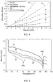
- FIG. 4 an acoustic frequency dependence of attenuation of the acoustic energy passing therethrough for different materials used in acoustic lens is shown. Symbols indicate measured data and lines indicate simulated dependencies.
- the presented materials show a steady increase of the attenuation value with the increase in frequency.
- the highest attenuation, which increases considerably with the frequency, is observed for the commonly used filled silicon rubber (RTV-560, curve 81): the attenuation reaches almost 5 dB/mm at a frequency around 7 MHz.
- the first layer including the polybutadiene material has acoustic wave velocity of about 1570 meters per second (m/s) and the second layer including the polymethylpentene material has acoustic wave velocity of about 2000 m/s.
- polybutadiene is a suitable material for acoustic impedance matching.
- the polybutadiene material has acoustic impedance of about 1.45 MRayl.
- Table 1 shows the measured changes in acoustic properties of the polybutadiene layer with the introduction of zirconium dioxide (ZrO 2 ) insulating particles having in average diameter of 2-3 micron and taking a fixed percentage of a total weight of the inner layer.
- Table 1 Changes in the density, acoustic wave velocity, acoustic impedance and attenuation (at frequency of 7 MHz) with an increasing weight percentage of ZrO 2 particles in the total weight of the polybutadiene layer.
- the acoustic impedance of the first layer can be tuned towards higher values, while the attenuation of the layer still remains below 1.5 dB/mm, even for the layers comprising 25% of its weight taken by the insulating particles (ZrO 2 ).
- the insulating particles ZrO 2
- the first layer of the lens comprising the polybutadiene with embedded insulating particles
- a density equal or above 0.94g/cm 3
- an acoustic impedance equal or above 1.5 MRayl
- a direct acoustical coupling of the acoustical window layer to the membrane of the CMUT cell is provided.
- the acoustic impedance equal or above 1.5 MRayl matched closer to the values in between the CMUTs acoustic impedance and the tissue.
- Thermoset elastomers selected from a hydrocarbon family have light molecular weight compared to commonly used in ultrasound silicon based rubbers (filled silicon). These elastomers, in particular polybutadiene, possess higher acoustic impedance. Therefore, in order to increase their impedance a relatively smaller amount of the filler may be used in this polymeric material, compared to the filled silicones. Since an introduction of the insulating particles to a layer on average increases its hardness, an application of the polybutadiene having higher acoustic impedance provides the first layer with relatively smaller changed hardness and a considerably lower attenuation (preferably below 1.5 for frequencies below 20MHz or 2 dB/mm for frequencies in between 20 and 25 MHz) than with filled silicones.
- Ceramic particles may be used: ZrO2, Al2O3, TiO2, Bi2O3 and BaSO4 (species of metal oxides). Ceramic particles show high insulating properties, which may be advantageous in providing additional insulation to the arrays electronics. Moreover, there are multiple ways developed in the art for manufacturing ceramic particles of a well-defined size.
- the reduced acoustic wave attenuation in the layers of polybutadiene and polybutadiene having 25% of the layer's total weight filled with ZrO 2 particles can be seen from the curves 85 and 845 in FIG.4 respectively.
- the polybutadiene with embedded insulating particles shows attenuation below 2 dB/mm at 10 MHz and below 1 dB/mm at 5 MHz.
- polymethylpentene (poly 4-methyl pentene-1) material used in the second layer provides an advantage of acoustic impedance tuning of the second layer.
- Polymethylpentene (available from Mitsui under trade name TPX) material shows a low longitudinal acoustic attenuation as can be seen from FIG.4 curve 83.
- the longitudinal attenuation corresponds to the wave's amplitude reduction while propagating from the inner surface arranged to face the array the outer surface.
- the TPX material has relatively low density, while due to its hardness exhibiting relatively high acoustic wave velocity (above 2 mm/msec).
- the TPX Compared to other more dense polymers with similar acoustic wave velocities, the TPX has relatively high acoustic wave velocity, while showing relatively low acoustic impedance of about 1.7 MRayl. However, as has been already indicated above that the TPX material has low shear wave attenuation. In contrast to the emitted ultrasound waves propagating from the ultrasound array throughout the lens 13 towards the patient, the shear wave travels along the acoustic window surface and increases the cross talk between the transducers affecting the ultrasound image quality. It may be also desired to bring the impedance of the second layer closer to the tissue impedance.
- the introduction of a polyolefin elastomer (POE) into the blend of the thermoplastic polymer polymethylpentene allows reducing the impedance of the blend (while increasing its density), which permits tuning acoustic properties of the second layer.
- this blend has an increased shear wave attenuation that beneficially reduces a cross talk between the transducer elements in the array 74. Therefore, the ultrasound probe 200 having the acoustic lens 13 with the second layer 42 formed from a blend of the polymethylpentene and polyolefin elastomer may show a reduction of image artefacts during the ultrasound imaging.
- Blending (compounding) of these polymer materials can, for instance, be performed with a twin screw extruder.
- the blend of the thermoplastic polymer and the elastomer represents a so called immiscible polymer blends (heterogeneous polymer blends), wherein the blend made of these two polymers exhibits two sets of distinct physical properties, such as glass transition temperatures and melting point, corresponding to the materials forming the blend.
- An additional advantage of the polyolefin elastomer that it is compatible with most olefinic materials, wherein olefinic is any of a class of unsaturated open-chain hydrocarbons having at least one double bond.
- POEs polyolefin based elastomers
- blending provides a homogenous distribution of the thermoplastic and elastomer materials within a given volume, without a formation of separate islands of different materials, wherein said islands can introduce additional sources of scattering for the ultrasound waves.
- the second layer of the lens comprises a blend of polymethylpentene and a copolymer forming the polyolefin elastomer.
- Copolymers are a physical mix of polymers (two different monomers) which consist of materials with different elastic properties.
- the copolymer of the polyolefin elastomer is a copolymer of ethylene and alpha olefin such as octane or butane.
- Alpha-olefins (or ⁇ -olefins) are a family of organic compounds which are alkenes with a chemical formula CnH 2n , distinguished by having a double bond at the primary or alpha ( ⁇ ) position.
- the outer layer comprises a blend of polymethylpentene and ethylene-octene copolymer. This copolymer is available from Dow Chemical under trade name Engage.
- the ethylene-octene copolymer is suitable for blending with polymethylpentene due to its olefin nature. This copolymer exhibits on average lower, than the TPX, acoustic impedance and almost an order of magnitude higher shear wave attenuation.
- the resulting blend of the TPX and ethylene-octene copolymer inherits from the TPX the reduced density with relatively high acoustic wave velocity; and from the copolymer reduced acoustic impedance and increased shear wave attenuation. Therefore, an improved outer layer 42 comprising the blend from the TPX and the ethylene-octene copolymer can be obtained.
- This blend provides the window layer of the acoustic probe with durability and low acoustic attenuation properties next to the improved imaging quality due to the reduced image artifacts originating from the window layer.
- Table 1 shows a comparison of the acoustic properties measured for different materials: polymethylpentene (Mitsui TPX MX0002, having 4 monomers in a polymer chain), polyolefin elastomer (Engage 8180 having 4 monomers in a polymer chain); two blends of the polymethylpentene (TPX MX0002) and polyolefin elastomer (Engage 8180), wherein an amount of the elastomer in the blend 15% and 20% of total blend's weight correspondingly.
- Table 2 shows a comparison of the acoustic properties measured for different materials: polymethylpentene (Mitsui TPX MX0002, having 4 monomers in a polymer chain), polyolefin elastomer (Engage 8180 having 4 monomers in a polymer chain); two blends of the polymethylpentene (TPX MX0002) and polyolefin elastomer (Engage 8180), wherein an amount of the
- Engage 8180 has the lowest density from the commercially available Engage types. Engage 8180 material shows a considerable attenuation of the shear wave (above 17 dB/mm) in addition it also shows the relatively high acoustic wave attenuation increasing from about 1.5 dB/mm at 2.5 MHz up to 5 dB/mm at 7.5 MHz.
- the blend of TPX and Engage 8180 wherein a weight ratio of 85% and 15% correspondingly, compared to the TPX, shows a slight increase in density up to 0.835 gram per cubic centimeter (g/cm 3 ) with an improved shear wave attenuation of about 5 dB/mm and an increased acoustic wave attenuation being about 2.71 dB/mm at 7.5 MHz.
- the acoustic impedance of the TPX and Engage 8180 (85/15%) blend is reduced down to 1.6 MRayl, compared to the TPX material, which brings acoustic impedance value of the outer layer 42 closer to the tissue impedance.
- the shear wave attenuation of the blend can be further improved (increased) by increasing the weight ratio of the Engage in the blend.
- the shear wave attenuation may be as high as 10 dB/mm with the acoustic impedance further reduced to 1.58MRayl.
- the blending of these polymers provides a freedom of varying the acoustic wave velocity of the blend by changing the weight ratio of the polymers in the blend depending on different medical applications.
- the second layer 42 formed from blend of thermoplastic olefin (polymethylpentene) and polyolefin elastomer (ethylene-octene copolymer) exhibits a low acoustic attenuation and reduced acoustic impedance that may be closer matched to the first layer 47 the body/ human tissue.
- the second layer forms the outer surface of the lens 13
- the second layer 42 provides low water permeation levels and lens improved resistant to disinfectants (used for typical medical ultrasound equipment). This property is attributed the fact that both components forming the blend are olefin based making the blend non-polar, therefore, chemically stable towards the disinfectant treatment commonly used for medical devices.
- the lens 13 comprising the second layer from the polymethylpentene blend also shows good mechanical properties (with respect to an impact and wear resistance).
- FIG. 5 shows the differential scanning calorimetry curves for polymethylpentene (TPX MX0002, curve 61); polymethylpentene/ polyolefin elastomer blends (TPX/Engage 8180) having the weight ratio of 80%/20% (curve 62) and 85%/15% (curve 63) correspondingly; and polyolefin elastomer (Engage 8180, curve 64).
- the heat flow temperature dependence has two extrema points around 50 and 225 centigrade Celsius.
- MP1 first melting point
- MP2 second melting point
- heat flow curves of pure Engage 64 and TPX 61 have one extreme point each: around 50 centigrade Celsius corresponding to the polyolefin elastomer (Engage, 64) and around 225 centigrade Celsius corresponding to thermoplastic polymer (TPX, 61).
- FIG.6 shows the dynamic mechanical analyses curves for the same set of materials.
- the loss modulus temperature dependence of the blends shows two extrema combining the properties of both blended materials.
- Tg1 first glass transition temperature
- Tg2 second glass transition temperature
- Tg2 thermoplastic polyolefin
- the loss modulus curves of pure Engage 64 and TPX 61 have one extreme point each: around -60 centigrade Celsius corresponding to the elastomer (Engage, 64) and around 25 centigrade Celsius corresponding to thermoplastic polyolefin (TPX, 61).
- CMUT cell is shown in FIG.3 .
- Such CMUT cell is typically fabricated on a substrate 4, such as a silicon wafer. This substrate may be located within the base 4' of the probe 200 in FIG.2 .
- An ultrasound array 74 of an ultrasound probe 200 comprises CMUT cells 6.
- the CMUT cells may be either individually activated or in combination with each other.
- the individual cells can have round, rectangular, hexagon or other peripheral shapes.
- Each CMUT cell has at least a pair of electrodes 7' and 7 separated by a cavity 8.
- the cavity 8 is formed in between a membrane 5 that is suspended over a cell floor 31 formed by the top surface of the substrate 4.
- the membrane 5 may be made of silicon nitride and is adapted to move or vibrate. It can be suspended over the cell floor 31 (or substrate) through a plurality of supporting portions 9 (in Fig.2 two supporting portions 9 are shown).
- the electrodes 7, 7' are made of electrically conductive material, such as metal.
- the bottom electrodes 7 may be embedded in the floor of the cell 31, while the top electrode 7' may be embedded in the membrane 5.
- the electrode 7 and 7' may be also deposited on the cell floor 31 or the membrane 5 as additional layers.
- the bottom electrode 7 is typically insulated on its cavity-facing surface with an additional layer (not shown).
- This insulating layer can comprise either one of or a combination of an oxide-nitride-oxide (ONO) dielectric layer, silicon oxide layer, aluminium or hafnium oxide layers.
- the insulating layer may be formed above the bottom electrode 7 and below the membrane electrode 7'.
- the ONO-dielectric layer advantageously reduces charge accumulation on the electrodes which leads to device instability, drift and reduction in acoustic output pressure.
- the supporting portions 9 may be made of an insulating material such as silicon oxide or silicon nitride.
- the cavity 8 can be either air- or gas-filled, or wholly or partially evacuated. Two electrodes 7 and 7' separated by the cavity 8 represent a capacitance.
- An application of electrical signal through a drive circuit 45 coupled to the electrodes 7 and 7' causes a mechanical movement/vibration of the membrane 5, which results in the change of the capacitance and can be manipulated by an associated with the CMUT transducer integrated circuitry.
- the drive circuit 45 can be implemented as an integrated part of the integrated circuitry of the ultrasound array.
- the drive circuit 45 usually comprises an a.c. signal voltage and a d.c. voltage sources and associated to these sources circuitry.
- a conventional PZT-based transducer typically has a parallelepiped shape, wherein at least one of its faces is adapted to vibrate in a piston-like motion during the transmission of the acoustic wave.
- the displacement of the vibrating (active) face is homogeneous throughout the face surface.
- the CMUT's vibrating membrane has a different displacement throughout the membrane's area (surface).
- the membrane's displacement is highest in the central part of the CMUT cell and lowest at the periphery of the membrane.
- a collapsed mode of operation as shown in FIG. 8 the membrane 5 of the CMUT cell 6 is partially contacting the cell floor, which results in the biggest membrane displacement (D) compared to the conventional operation mode.
- a central part of the membrane 46 may be brought into the contact with (collapsed to) the cell floor by applying a collapsed d.c. voltage value (the d.c. voltage is supplied by the drive circuitry 45). The applied a.c.
- the CMUT with the collapsed membrane can in principle be manufactured in any conventional way, comprising providing a CMUT with a membrane and applying different means, such as electrical (bias voltage) or pressure, in order to bring the membrane to a collapsed state.
- electrical bias voltage
- the displacement D of the central part of the membrane is fixed, while the suspended portions of the membrane vibrate with an amplitude d, which is determined by the a.c. voltage signal for the given CMUT cell design.
- the variation in the displacement of the membrane's vibrating portions imposes different requirements on the lens layer being acoustically coupled to the CMUT array in order to provide an improved acoustic coupling of the operating CMUT transducer.
- the layer forming an acoustical contact with the CMUT may need to adopt its inner surface to the membrane's displacement.
- the relatively light molecular weight of the polybutadiene combined with its relatively low hardness (below 60 ShoreA, preferably below 50 ShoreA) may provide an improved acoustic contact between the acoustic window layer 13 and the CMUT's membrane adapted to vibrate.
- the low acoustic wave attenuation of the material forming the inner layer may provide an improved transition of the wave throughout the lens 13.
- the acoustic lens of the present invention comprises the first layer 47 including the thermoset elastomer having a polymeric material selected from a hydrocarbon family, such as polybutadiene, and may comprise insulting particles embedded therein; and the second layer 42 comprising the thermoplastic polymer polymethylpentene, and elastomer selected from the polyolefin family (POE) blended therein for acoustic impedance adjustment.
- the first layer 47 including the thermoset elastomer having a polymeric material selected from a hydrocarbon family, such as polybutadiene, and may comprise insulting particles embedded therein
- the second layer 42 comprising the thermoplastic polymer polymethylpentene, and elastomer selected from the polyolefin family (POE) blended therein for acoustic impedance adjustment.
- POE polyolefin family
- the CMUT array is preferably arranged to operate in the collapsed mode by comprising at least one drive circuit 45 coupled to the CMUT cell 6 and adapted to (a) bring the membrane 5 into a collapsed state in which the membrane is collapsed to the substrate 4 , by applying a d.c. voltage over the first 7 and the second electrodes 7' of the at least one CMUT cell, and (b) activate the CMUT cell by applying an a.c. voltage over the first and the second electrodes of the at least one said CMUT cell.
- the CMUT ultrasound array may transmit or receive ultrasound acoustic at different frequencies by varying the applied d.c. voltage, which in return changes the contact area of the membrane 5 with the substrate 4.
- the larger the d.c. voltage the larger the contact area in the collapsed mode and the higher the resonance frequency of the CMUT cell. Therefore, compared to the PZT-based array the CMUT-based ultrasound array may impose additional requirements onto the acoustic lens 13 in order to provide improved acoustic wave propagation for a large frequency range, in which the CMUT ultrasound array is adapted to operate. Therefore, it is desirable to have both the fisrt 47 and the second 42 layers showing reduced acoustic wave attenuation within the broad band of the operating frequencies.
- FIG. 7 shows an output pressure (MPa) in the frequency range from 0 up to 35 MHz for the CMUT ultrasound array acoustically coupled to layers of different different materials.
- Curve 65 corresponds to the ultrasound array overlaid by a common for the PZT application filled silicon rubber (RTV) of 1.2 millimeter in thickness.
- RTV PZT application filled silicon rubber
- the silicon rubber layer has poor performance for the CMUT array in this range of frequencies manifesting in the low output pressure reaching its maximum of 1.5 MPa around 5MHz; beyond frequencies of 7 MHz the filled silicon rubber exhibits a strong attenuation of the acoustic signal.
- the CMUT array overlaid by the first layer comprising polybutadiene material (curve 67) having a thickness of 30 micrometer shows an ultra-wide bandwidth with an output pressure reaching as high as 3.5 MPa.
- Curve 66 corresponds to the acoustic window layer 13 comprising both the first layer 47 formed by polybutadiene (30 micrometer thick) and the second layer 42 formed by polymethylpentene having a thickness of 200 micrometer.
- the output pressure for this array reaches as high as 2.5 MPa and is above 2 MPa in a broad frequency range from 7 up to 22 MHz.
- present invention provides a converging acoustic lens with improved acoustic wave transmission and the wide frequency bandwidths, characterized with low acoustic wave attenuation, combined with the durable and cleanable outer surface 71 of the lens 13.
- FIG.9 illustrates an example of the acoustic impedance matching, which can be implemented in the present invention.
- Curve 68 shows the acoustic frequency dependence of the acoustic loss (in dB) per millimeter for acoustic energy passing through the first layer of polybutadiene comprising 25% of ZrO 2 particles embedded therein (filled circles indicate measured data); and 69 shows the same dependence of the acoustic loss for acoustic energy passing through the second layer comprising a blend of polymethylpentene with 20% of Engage (filled squares indicate measured data).
- Both layers exhibit losses below 3 dB/mm for frequencies below 7 MHz, said frequency range comprises a region for general imaging in ultrasound diagnostic application.
- the percentage of ZrO 2 particles in polybutadiene relates to the percentage of Engage in the polymethylpentene blend such that the acoustic impedances of both layers are about the same 1.6 MRayl. This provides virtually no interface (due to the same impedance values) in between the first and second layer for the acoustic energy traveling therethrough. Thus, the reflection of the acoustic waves at the boundary of the lens layers is minimized.
- the density value of polybutadiene comprising 25% of ZrO 2 is about 1.09 g/cm 3 , while the acoustic wave velocity is about 1470 m/s; the density value of the polymethylpentene blend comprising 20% of Engage is about 0.8 g/cm 3 , while the acoustic wave velocity is about 1900 m/s.
- the refraction index of the lens 13 is 1.29 and the curvature radius of the convex surface 40 is 1.5 cm, with maximum thickness of the first layer being 1.5 mm.
- the maximum thickness (t) and the curvature radius (R) would change with the size of the array (probe's aperture size).
- FIG.10 gives a full acoustical wave analysis (spatial pressure distribution generated by the probe in Pascal units) in a broad range of frequencies for the lens constructed in accordance to the example above.
- the total thickness of the lens is 2 mm, 1.5 mm of which is the maximum thickness of the first layer.
- the curvature radius of the convex shaped surface of the first layer with polybutadiene is 1.3 cm. Without the lens, a natural focus of this array is at about 1.7 cm. An application of the lens to the array enhances focusing and the focal point is shifted to larger distances of 2.5 cm. Increasing a total thickness of the lens may further improve focusing (at the cost of increased attenuation). For example, with an accepted attenuation level using the same 1.3 mm radius of curvature, the thicker lens move can move the focal point to 3.0-3.5 cm, which comes closer to the first order approximation discussed above.
- the CMUT based arrays may find their common application is ultrasound imaging based disposable products, such as interventional ultrasound probes or on body patches. These applications have stricter requirements with respect to the sterility.
- the application of the second layer comprising the thermoplastic polymer polymethylpentene and the elastomer selected from the polyolefin family (POE) blended therein enables the focusing function of the acoustic lens, while also providing said lens with mechanical and chemical stability making an ultrasound device having such a lens suitable for the sterilization with common chemicals.
- An additional benefit of the present invention is that suggested layer materials are moldable and can be easier adapted to industrial manufacturing of the ultrasound probes.
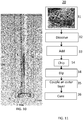
- FIG.11 a method 20 for manufacturing an ultrasound array comprising the acoustic lens in accordance with the present invention is illustrated.
- a granulate of pre-polymerized polybutadiene 38 (CB728T from Lanxess) is provided in step 31.
- the block is granulated and dissolved in solvents like alkanes, branched or cyclic alkanes, for example hexane, heptane, cyclohexane.
- step 33 the optimization of the acoustic impedance of the first layer can be achieved by adding insulating particles to the solvent, wherein the polymeric material act as a dispersion agent for the particles, such that a liquid mixture of the polymeric material and the insulating particles is provided.
- the additional dispersion agents like fatty acids (a carboxylic acid with an aliphatic chain, which is either saturated or unsaturated) may be added in the liquid mixture.
- the filler particles in the liquid mixture may increase the hardness of the inner layer of the acoustic window, while fatty acids may counter play this hardness increase keeping the average hardness of the first layer at the relatively constant value.
- the unsaturated chains of fatty acid like oleic acid, linoleic acid and linolenic acid can polymerise and bond to the polybutadiene chains. This provides a good dispersion/distribution of particles in the liquid mixture.
- a chip having the ultrasound array with the CMUT cells coupled to an integrated circuitry is provided.
- the chip is dipped in the liquid mixture, such that a layer comprising the liquid mixture overlays the CMUT cells. Since in step 33 a minimum impedance mismatch between the liquid mixture and the propagating medium can be achieved, the tolerance to the thickness variation of the liquid mixture layer is rather high. The increase in the dipping time would increase the thickness of the liquid mixture layer.
- the chip with the liquid mixture layer may be let drying at elevated temperature of about 70°C. With the time, when the solvent starts evaporating from the liquid mixture, the liquid mixture layer may become more solid (sticky).
- the second layer of the thermoplastic polymer polymethylpentene with the polyolefin elastomer blended therein is applied to the liquid mixture layer. The advantage of this step is that the second layer can be coupled to the first layer without any glue.
- the preferred weight ratio of the polyolefin elastomer in the blend of the thermoplastic polymer polymethylpentene is below 40%.
- the elastomer's weight ratio increase beyond 40% introduces too high attenuation in the outer layer.
- an optimal balance between the decreased acoustic impedance, reduced shear wave propagation and increased acoustic wave attenuation is achieved.
- the preferred weight ratio of the polyolefin elastomer in the thermoplastic polymer polymethylpentene blend is in between 10% and 30%, in particular in between 15% and 20%.
- the exact value of the selected weight ratio of both blend components and particles may depend on the medical application of the ultrasound array. For example, for low frequency applications (below 5 MHz) a relatively higher weight ratio may be selected for the particles 20-25% and about 25-30% for the polyolefin elastomer since the lens attenuation may be kept 2 dB/mm. In a higher frequency range (in between 5 MHz and 10 MHz), in order to keep the attenuation below 2 dB/mm, the lower weight ratio of the polyolefin elastomer in the blend may be selected, for example about 15%-20%.
- step 36 the layer overlaying the CMUT cell is cured at a temperature sufficient to evaporate the remaining solvent (about 100°C, in the case of heptane) from the liquid mixture layer.
- This method can be advantageously applied on industrial scale owing to the simplicity of the steps and large tolerance of the ultrasound array's performance to the acoustic layer thickness.
- Each layer thickness can be increased by repeating the steps of dipping 34 and drying 36. Due to the possibility of the impedance optimization in steps 33 and 35 low attenuation properties of the hydrocarbon materials, a local thickness deviation in the acoustic window layer from the average value can be higher than the accepted standard in commonly used spray or spin coat manufacturing. In addition to this manufacturing method provides flexibility in different chip designs and electrical contact bonding implemented in the array.
- the method can be also beneficially used for different chip size, especially in the area miniaturized ultrasound arrays, such as interventional devices and catheters.
- FIG. 12 illustrates the principle design of an ultrasonic imaging system 202.
- the ultrasound imaging system is generally denoted with reference numeral 202.
- the ultrasound imaging system 202 is used for scanning an area or volume of the body, e.g. of a patient 201. It is to be understood that the ultrasound system 202 may also be used for scanning other areas or volumes, e.g. body parts of animals or other living beings.
- an ultrasound probe 200 may be provided.
- the ultrasound probe 200 is connected to a console device 203.
- the console device 203 is shown in FIG. 12 as a mobile console. This console 203 may, however, also be realized as a stationary device.
- the console device 203 is connected to the probe 200 via an interface 206 formed in a wired manner. Further, it is contemplated that the console device 203 may also be connected to the probe 200 in a wireless manner, for example using UWB transmission technology.
- the console device 203 may further comprise an input device 205.
- the input device may have buttons, a key pad and/or a touchscreen to provide an input mechanism to a user of the ultrasound imaging system 202. Additionally or alternatively, other mechanisms may be present in the input device 205 to enable a user to control the ultrasound imaging system 202.
- the console device 203 comprises a display 204 to display data generated by the ultrasound imaging system 202 to the user.
- the volume within the patient 201 that is scanned via the ultrasound probe 200 can be viewed on the console device 203 by the user of the ultrasound system 200.
- the ultrasound probe 200 comprises the CMUT transducer array constructed in accordance with the present invention.
Claims (12)
- Eine akustische Linse (13) für ein Ultraschall-Array mit kapazitiven mikromechanischen Wandlern (74), die Folgendes umfasst:- eine erste Schicht (47) aus einem Duroplast-Elastomer mit einem Polymermaterial aus einer Kohlenwasserstofffamilie, wobei die erste Schicht über eine Innenfläche gegenüber dem Array sowie eine konvex geformte Außenfläche (40) gegenüber der Innenfläche verfügt; und- eine zweite Schicht (42) an der konvex geformten Außenfläche der ersten Schicht, die
ein Elastomer aus einer Polyolefinfamilie enthält, wobei die erste Schicht eine erste Schallwellengeschwindigkeit und die zweite Schicht eine zweite Schallwellengeschwindigkeit aufweist, und wobei die zweite Wellengeschwindigkeit größer ist als die erste Wellengeschwindigkeit,
und die sich dadurch auszeichnet, dass die zweite Schicht (42) über eine ebene Außenfläche (71) verfügt, und dass
die zweite Schicht (42) ein thermoplastisches Polymer-Polymethylpenten enthält, wobei das Elastomer aus einer Polyolefinfamilie hiermit vermischt wurde. - Die akustische Linse gemäß Anspruch 1, wobei das Kohlenwasserstoff-Elastomer Polybutadien enthält.
- Die akustische Linse gemäß Anspruch 1 oder 2, wobei es sich beim ausgewählten Elastomer um ein thermoplastisches Elastomer handelt.
- Die akustische Linse gemäß Anspruch 2, wobei die erste Schicht mit Polybutadien zudem Partikel (41) enthält, um eine Anpassung des Schallwellenwiderstands der ersten Schicht zu ermöglichen.
- Die akustische Linse gemäß Anspruch 4, wobei der prozentuale Gewichtsanteil der Partikel beruhend auf dem Gesamtgewicht der ersten Schicht am prozentualen Gewichtsanteil des ausgewählten Elastomers beruhend auf dem Gesamtgewicht der zweiten Schicht so ausgerichtet ist, dass der Schallwellenwiderstand der ersten Schicht im wesentlich mit dem Schallwellenwiderstand der zweiten Schicht identisch ist.
- Die akustische Linse gemäß Anspruch 5, wobei der Schallwellenwiderstand der ersten und zweiten Schicht etwa 1,6 MRayl beträgt.
- Die akustische Linse gemäß Anspruch 4, wobei die Partikel der ersten Schicht Keramikpartikel umfassen und das ausgewählte Elastomer ein Copolymer enthält, bei dessen ersten Monomer es sich um ein Alpha-Olefin und bei dessen zweiten Monomer es sich um Äthylen handelt.
- Die akustische Linse gemäß Anspruch 7, wobei die Keramikpartikel Zirkoniumdioxid-Partikel enthalten.
- Die akustische Linse gemäß Anspruch 8, wobei der prozentuale Gewichtsanteil der Keramikpartikel beruhend auf dem Gesamtgewicht der ersten Schicht höchstens 25 % beträgt, während der prozentuale Gewichtsanteil des ausgewählten Elastomers beruhend auf dem Gesamtgewicht der zweiten Schicht höchstens 40 % beträgt.
- Die akustische Linse gemäß Anspruch 8, wobei der prozentuale Gewichtsanteil der Zirkoniumdioxid-Partikel beruhend auf dem Gesamtgewicht der ersten Schicht etwa 25 % beträgt, während der prozentuale Gewichtsanteil des ausgewählten Elastomers beruhend auf dem Gesamtgewicht der zweiten Schicht etwa 20 % beträgt.
- Die akustische Linse gemäß Anspruch 1,
wobei die Schallwellenwiderstandsdifferenz zwischen der ersten und zweiten Schicht kleiner als 0,3 MRayl ist. - Eine Ultraschallsonde (200),
die die akustische Linse gemäß einer der Ansprüche 1 bis 11 umfasst.
Applications Claiming Priority (2)
| Application Number | Priority Date | Filing Date | Title |
|---|---|---|---|
| EP15200991 | 2015-12-18 | ||
| PCT/EP2016/081526 WO2017103172A1 (en) | 2015-12-18 | 2016-12-16 | An acoustic lens for an ultrasound array |
Publications (2)
| Publication Number | Publication Date |
|---|---|
| EP3389878A1 EP3389878A1 (de) | 2018-10-24 |
| EP3389878B1 true EP3389878B1 (de) | 2020-08-19 |
Family
ID=55027354
Family Applications (1)
| Application Number | Title | Priority Date | Filing Date |
|---|---|---|---|
| EP16810411.5A Active EP3389878B1 (de) | 2015-12-18 | 2016-12-16 | Akustische linse für eine ultraschallanordnung |
Country Status (5)
| Country | Link |
|---|---|
| US (1) | US11386883B2 (de) |
| EP (1) | EP3389878B1 (de) |
| JP (1) | JP6766149B2 (de) |
| CN (1) | CN108430651B (de) |
| WO (1) | WO2017103172A1 (de) |
Families Citing this family (5)
| Publication number | Priority date | Publication date | Assignee | Title |
|---|---|---|---|---|
| US10809166B2 (en) * | 2017-01-20 | 2020-10-20 | Matchstick Technologies, Inc. | Ultrasound system for shearing cellular material in a microplate |
| JP6944885B2 (ja) | 2018-02-02 | 2021-10-06 | オリンパス株式会社 | 超音波振動子及び超音波内視鏡 |
| US11164559B2 (en) | 2018-04-30 | 2021-11-02 | Toyota Motor Engineering & Manufacturing North America, Inc. | Selective sound transmission and active sound transmission control |
| EP3590437A1 (de) | 2018-07-02 | 2020-01-08 | Koninklijke Philips N.V. | Akustisch transparentes fenster für intraluminale ultraschallabbildungsvorrichtung |
| JP7291498B2 (ja) * | 2019-02-26 | 2023-06-15 | キヤノンメディカルシステムズ株式会社 | 超音波プローブ、超音波診断装置、および音響カプラ |
Citations (1)
| Publication number | Priority date | Publication date | Assignee | Title |
|---|---|---|---|---|
| EP3374095A1 (de) * | 2015-11-10 | 2018-09-19 | Koninklijke Philips N.V. | Akustische fensterschicht für ein ultraschallarray |
Family Cites Families (27)
| Publication number | Priority date | Publication date | Assignee | Title |
|---|---|---|---|---|
| US4387720A (en) * | 1980-12-29 | 1983-06-14 | Hewlett-Packard Company | Transducer acoustic lens |
| US4503861A (en) * | 1983-04-11 | 1985-03-12 | Biomedics, Inc. | Fetal heartbeat doppler transducer |
| JPS59225044A (ja) * | 1983-06-07 | 1984-12-18 | 松下電器産業株式会社 | 超音波トランスジユ−サ |
| DE3787746T2 (de) * | 1986-04-02 | 1994-02-17 | Matsushita Electric Ind Co Ltd | Ultraschallwandler mit einem Ultraschallfortpflanzungsmedium. |
| JPH07121158B2 (ja) * | 1987-01-19 | 1995-12-20 | オムロン株式会社 | 超音波探触子 |
| US5423220A (en) * | 1993-01-29 | 1995-06-13 | Parallel Design | Ultrasonic transducer array and manufacturing method thereof |
| US5577507A (en) * | 1994-11-21 | 1996-11-26 | General Electric Company | Compound lens for ultrasound transducer probe |
| US5984871A (en) * | 1997-08-12 | 1999-11-16 | Boston Scientific Technologies, Inc. | Ultrasound transducer with extended focus |
| JP4256309B2 (ja) * | 2003-09-29 | 2009-04-22 | 株式会社東芝 | 超音波プローブおよび超音波診断装置 |
| US7348712B2 (en) * | 2004-04-16 | 2008-03-25 | Kabushiki Kaisha Toshiba | Ultrasonic probe and ultrasonic diagnostic apparatus |
| US7359124B1 (en) * | 2004-04-30 | 2008-04-15 | Louisiana Tech University Research Foundation As A Division Of The Louisiana Tech University Foundation | Wide-angle variable focal length lens system |
| US7750536B2 (en) * | 2006-03-02 | 2010-07-06 | Visualsonics Inc. | High frequency ultrasonic transducer and matching layer comprising cyanoacrylate |
| US7888847B2 (en) * | 2006-10-24 | 2011-02-15 | Dennis Raymond Dietz | Apodizing ultrasonic lens |
| JP4958631B2 (ja) * | 2007-05-14 | 2012-06-20 | 株式会社日立製作所 | 超音波送受信デバイス及びそれを用いた超音波探触子 |
| DE102008014120A1 (de) * | 2008-03-13 | 2009-09-24 | Fraunhofer-Gesellschaft zur Förderung der angewandten Forschung e.V. | Ultraschallwandler mit akustischer Anpassungsschicht für hohe Ultraschallfrequenzen sowie Verfahren zur Herstellung der Anpassungsschicht |
| JP5723775B2 (ja) * | 2008-09-18 | 2015-05-27 | ビジュアルソニックス インコーポレイテッド | 超音波変換器および他の構成要素の製造方法 |
| WO2010038162A1 (en) * | 2008-09-30 | 2010-04-08 | Koninklijke Philips Electronics, N.V. | System and method for ultrasound therapy treatment |
| EP2405671A4 (de) * | 2009-03-04 | 2014-04-02 | Panasonic Corp | Ultraschallwandler, ultraschallsonde und ultraschalldiagnosegerät |
| EP2444166A1 (de) * | 2009-09-15 | 2012-04-25 | Fujifilm Corporation | Ultraschallwandler, Ultraschallsonde und Herstellungsverfahren |
| JP5672823B2 (ja) * | 2010-07-30 | 2015-02-18 | コニカミノルタ株式会社 | 超音波探触子用バッキング材、それを用いた超音波探触子、及び超音波医用画像診断装置 |
| JP5860822B2 (ja) * | 2012-02-13 | 2016-02-16 | 富士フイルム株式会社 | 音響波検出用のプローブおよびそれを備えた光音響計測装置 |
| US9221077B2 (en) * | 2012-05-09 | 2015-12-29 | Kolo Technologies, Inc. | CMUT assembly with acoustic window |
| US9502023B2 (en) * | 2013-03-15 | 2016-11-22 | Fujifilm Sonosite, Inc. | Acoustic lens for micromachined ultrasound transducers |
| WO2015028325A1 (en) * | 2013-08-30 | 2015-03-05 | Koninklijke Philips N.V. | Capacitive micro-machined ultrasound transducer cell |
| WO2015095721A1 (en) * | 2013-12-20 | 2015-06-25 | Fujifilm Sonosite, Inc. | High frequency ultrasound transducers |
| US10265047B2 (en) * | 2014-03-12 | 2019-04-23 | Fujifilm Sonosite, Inc. | High frequency ultrasound transducer having an ultrasonic lens with integral central matching layer |
| US11358174B2 (en) * | 2015-03-03 | 2022-06-14 | Koninklijke Philips N.V. | CMUT array comprising an acoustic window layer |
-
2016
- 2016-12-16 US US16/062,656 patent/US11386883B2/en active Active
- 2016-12-16 WO PCT/EP2016/081526 patent/WO2017103172A1/en active Application Filing
- 2016-12-16 CN CN201680073398.9A patent/CN108430651B/zh not_active Expired - Fee Related
- 2016-12-16 JP JP2018531223A patent/JP6766149B2/ja active Active
- 2016-12-16 EP EP16810411.5A patent/EP3389878B1/de active Active
Patent Citations (1)
| Publication number | Priority date | Publication date | Assignee | Title |
|---|---|---|---|---|
| EP3374095A1 (de) * | 2015-11-10 | 2018-09-19 | Koninklijke Philips N.V. | Akustische fensterschicht für ein ultraschallarray |
Also Published As
| Publication number | Publication date |
|---|---|
| US11386883B2 (en) | 2022-07-12 |
| CN108430651A (zh) | 2018-08-21 |
| WO2017103172A1 (en) | 2017-06-22 |
| JP6766149B2 (ja) | 2020-10-07 |
| JP2019504547A (ja) | 2019-02-14 |
| US20180374471A1 (en) | 2018-12-27 |
| EP3389878A1 (de) | 2018-10-24 |
| CN108430651B (zh) | 2020-09-01 |
Similar Documents
| Publication | Publication Date | Title |
|---|---|---|
| EP3389878B1 (de) | Akustische linse für eine ultraschallanordnung | |
| EP3374095B1 (de) | Akustische fensterschicht für ein ultraschallarray | |
| EP3265243B1 (de) | Cmut-array mit einer schallfensterschicht | |
| US11358174B2 (en) | CMUT array comprising an acoustic window layer | |
| US11278932B2 (en) | Capacitive micro-machined ultrasound transducer cell | |
| WO2007088772A1 (ja) | 超音波探触子 | |
| US11529120B2 (en) | Ultrasound device contacting | |
| CN109069107B (zh) | 超声设备接触 | |
| WO2014013735A1 (ja) | 超音波探触子 | |
| JPH08615A (ja) | 超音波診断装置用接触子の音響レンズ | |
| JP2013042248A (ja) | 超音波探触子、超音波画像診断装置及び超音波探触子の製造方法 | |
| JPWO2010119729A1 (ja) | 音響レンズの製造方法、超音波探触子、および超音波診断装置 | |
| JP2013034138A (ja) | 超音波探触子及び超音波画像診断装置、音響レンズの製造方法及び整合層の製造方法 |
Legal Events
| Date | Code | Title | Description |
|---|---|---|---|
| STAA | Information on the status of an ep patent application or granted ep patent |
Free format text: STATUS: UNKNOWN |
|
| STAA | Information on the status of an ep patent application or granted ep patent |
Free format text: STATUS: THE INTERNATIONAL PUBLICATION HAS BEEN MADE |
|
| PUAI | Public reference made under article 153(3) epc to a published international application that has entered the european phase |
Free format text: ORIGINAL CODE: 0009012 |
|
| STAA | Information on the status of an ep patent application or granted ep patent |
Free format text: STATUS: REQUEST FOR EXAMINATION WAS MADE |
|
| 17P | Request for examination filed |
Effective date: 20180718 |
|
| AK | Designated contracting states |
Kind code of ref document: A1 Designated state(s): AL AT BE BG CH CY CZ DE DK EE ES FI FR GB GR HR HU IE IS IT LI LT LU LV MC MK MT NL NO PL PT RO RS SE SI SK SM TR |
|
| AX | Request for extension of the european patent |
Extension state: BA ME |
|
| STAA | Information on the status of an ep patent application or granted ep patent |
Free format text: STATUS: EXAMINATION IS IN PROGRESS |
|
| 17Q | First examination report despatched |
Effective date: 20190219 |
|
| DAV | Request for validation of the european patent (deleted) | ||
| DAX | Request for extension of the european patent (deleted) | ||
| GRAP | Despatch of communication of intention to grant a patent |
Free format text: ORIGINAL CODE: EPIDOSNIGR1 |
|
| STAA | Information on the status of an ep patent application or granted ep patent |
Free format text: STATUS: GRANT OF PATENT IS INTENDED |
|
| RAP1 | Party data changed (applicant data changed or rights of an application transferred) |
Owner name: KONINKLIJKE PHILIPS N.V. |
|
| INTG | Intention to grant announced |
Effective date: 20200311 |
|
| GRAS | Grant fee paid |
Free format text: ORIGINAL CODE: EPIDOSNIGR3 |
|
| GRAA | (expected) grant |
Free format text: ORIGINAL CODE: 0009210 |
|
| STAA | Information on the status of an ep patent application or granted ep patent |
Free format text: STATUS: THE PATENT HAS BEEN GRANTED |
|
| AK | Designated contracting states |
Kind code of ref document: B1 Designated state(s): AL AT BE BG CH CY CZ DE DK EE ES FI FR GB GR HR HU IE IS IT LI LT LU LV MC MK MT NL NO PL PT RO RS SE SI SK SM TR |
|
| REG | Reference to a national code |
Ref country code: CH Ref legal event code: EP |
|
| REG | Reference to a national code |
Ref country code: DE Ref legal event code: R096 Ref document number: 602016042421 Country of ref document: DE |
|
| REG | Reference to a national code |
Ref country code: AT Ref legal event code: REF Ref document number: 1303346 Country of ref document: AT Kind code of ref document: T Effective date: 20200915 |
|
| REG | Reference to a national code |
Ref country code: IE Ref legal event code: FG4D |
|
| REG | Reference to a national code |
Ref country code: LT Ref legal event code: MG4D |
|
| REG | Reference to a national code |
Ref country code: NL Ref legal event code: MP Effective date: 20200819 |
|
| PG25 | Lapsed in a contracting state [announced via postgrant information from national office to epo] |
Ref country code: BG Free format text: LAPSE BECAUSE OF FAILURE TO SUBMIT A TRANSLATION OF THE DESCRIPTION OR TO PAY THE FEE WITHIN THE PRESCRIBED TIME-LIMIT Effective date: 20201119 Ref country code: GR Free format text: LAPSE BECAUSE OF FAILURE TO SUBMIT A TRANSLATION OF THE DESCRIPTION OR TO PAY THE FEE WITHIN THE PRESCRIBED TIME-LIMIT Effective date: 20201120 Ref country code: NO Free format text: LAPSE BECAUSE OF FAILURE TO SUBMIT A TRANSLATION OF THE DESCRIPTION OR TO PAY THE FEE WITHIN THE PRESCRIBED TIME-LIMIT Effective date: 20201119 Ref country code: PT Free format text: LAPSE BECAUSE OF FAILURE TO SUBMIT A TRANSLATION OF THE DESCRIPTION OR TO PAY THE FEE WITHIN THE PRESCRIBED TIME-LIMIT Effective date: 20201221 Ref country code: HR Free format text: LAPSE BECAUSE OF FAILURE TO SUBMIT A TRANSLATION OF THE DESCRIPTION OR TO PAY THE FEE WITHIN THE PRESCRIBED TIME-LIMIT Effective date: 20200819 Ref country code: LT Free format text: LAPSE BECAUSE OF FAILURE TO SUBMIT A TRANSLATION OF THE DESCRIPTION OR TO PAY THE FEE WITHIN THE PRESCRIBED TIME-LIMIT Effective date: 20200819 Ref country code: SE Free format text: LAPSE BECAUSE OF FAILURE TO SUBMIT A TRANSLATION OF THE DESCRIPTION OR TO PAY THE FEE WITHIN THE PRESCRIBED TIME-LIMIT Effective date: 20200819 Ref country code: FI Free format text: LAPSE BECAUSE OF FAILURE TO SUBMIT A TRANSLATION OF THE DESCRIPTION OR TO PAY THE FEE WITHIN THE PRESCRIBED TIME-LIMIT Effective date: 20200819 |
|
| REG | Reference to a national code |
Ref country code: AT Ref legal event code: MK05 Ref document number: 1303346 Country of ref document: AT Kind code of ref document: T Effective date: 20200819 |
|
| PG25 | Lapsed in a contracting state [announced via postgrant information from national office to epo] |
Ref country code: IS Free format text: LAPSE BECAUSE OF FAILURE TO SUBMIT A TRANSLATION OF THE DESCRIPTION OR TO PAY THE FEE WITHIN THE PRESCRIBED TIME-LIMIT Effective date: 20201219 Ref country code: PL Free format text: LAPSE BECAUSE OF FAILURE TO SUBMIT A TRANSLATION OF THE DESCRIPTION OR TO PAY THE FEE WITHIN THE PRESCRIBED TIME-LIMIT Effective date: 20200819 Ref country code: LV Free format text: LAPSE BECAUSE OF FAILURE TO SUBMIT A TRANSLATION OF THE DESCRIPTION OR TO PAY THE FEE WITHIN THE PRESCRIBED TIME-LIMIT Effective date: 20200819 Ref country code: RS Free format text: LAPSE BECAUSE OF FAILURE TO SUBMIT A TRANSLATION OF THE DESCRIPTION OR TO PAY THE FEE WITHIN THE PRESCRIBED TIME-LIMIT Effective date: 20200819 Ref country code: NL Free format text: LAPSE BECAUSE OF FAILURE TO SUBMIT A TRANSLATION OF THE DESCRIPTION OR TO PAY THE FEE WITHIN THE PRESCRIBED TIME-LIMIT Effective date: 20200819 |
|
| PG25 | Lapsed in a contracting state [announced via postgrant information from national office to epo] |
Ref country code: CZ Free format text: LAPSE BECAUSE OF FAILURE TO SUBMIT A TRANSLATION OF THE DESCRIPTION OR TO PAY THE FEE WITHIN THE PRESCRIBED TIME-LIMIT Effective date: 20200819 Ref country code: DK Free format text: LAPSE BECAUSE OF FAILURE TO SUBMIT A TRANSLATION OF THE DESCRIPTION OR TO PAY THE FEE WITHIN THE PRESCRIBED TIME-LIMIT Effective date: 20200819 Ref country code: RO Free format text: LAPSE BECAUSE OF FAILURE TO SUBMIT A TRANSLATION OF THE DESCRIPTION OR TO PAY THE FEE WITHIN THE PRESCRIBED TIME-LIMIT Effective date: 20200819 Ref country code: SM Free format text: LAPSE BECAUSE OF FAILURE TO SUBMIT A TRANSLATION OF THE DESCRIPTION OR TO PAY THE FEE WITHIN THE PRESCRIBED TIME-LIMIT Effective date: 20200819 Ref country code: EE Free format text: LAPSE BECAUSE OF FAILURE TO SUBMIT A TRANSLATION OF THE DESCRIPTION OR TO PAY THE FEE WITHIN THE PRESCRIBED TIME-LIMIT Effective date: 20200819 |
|
| REG | Reference to a national code |
Ref country code: DE Ref legal event code: R097 Ref document number: 602016042421 Country of ref document: DE |
|
| PG25 | Lapsed in a contracting state [announced via postgrant information from national office to epo] |
Ref country code: AT Free format text: LAPSE BECAUSE OF FAILURE TO SUBMIT A TRANSLATION OF THE DESCRIPTION OR TO PAY THE FEE WITHIN THE PRESCRIBED TIME-LIMIT Effective date: 20200819 Ref country code: AL Free format text: LAPSE BECAUSE OF FAILURE TO SUBMIT A TRANSLATION OF THE DESCRIPTION OR TO PAY THE FEE WITHIN THE PRESCRIBED TIME-LIMIT Effective date: 20200819 Ref country code: ES Free format text: LAPSE BECAUSE OF FAILURE TO SUBMIT A TRANSLATION OF THE DESCRIPTION OR TO PAY THE FEE WITHIN THE PRESCRIBED TIME-LIMIT Effective date: 20200819 |
|
| PLBE | No opposition filed within time limit |
Free format text: ORIGINAL CODE: 0009261 |
|
| STAA | Information on the status of an ep patent application or granted ep patent |
Free format text: STATUS: NO OPPOSITION FILED WITHIN TIME LIMIT |
|
| PG25 | Lapsed in a contracting state [announced via postgrant information from national office to epo] |
Ref country code: SK Free format text: LAPSE BECAUSE OF FAILURE TO SUBMIT A TRANSLATION OF THE DESCRIPTION OR TO PAY THE FEE WITHIN THE PRESCRIBED TIME-LIMIT Effective date: 20200819 |
|
| 26N | No opposition filed |
Effective date: 20210520 |
|
| PG25 | Lapsed in a contracting state [announced via postgrant information from national office to epo] |
Ref country code: IT Free format text: LAPSE BECAUSE OF FAILURE TO SUBMIT A TRANSLATION OF THE DESCRIPTION OR TO PAY THE FEE WITHIN THE PRESCRIBED TIME-LIMIT Effective date: 20200819 |
|
| REG | Reference to a national code |
Ref country code: CH Ref legal event code: PL |
|
| PG25 | Lapsed in a contracting state [announced via postgrant information from national office to epo] |
Ref country code: SI Free format text: LAPSE BECAUSE OF FAILURE TO SUBMIT A TRANSLATION OF THE DESCRIPTION OR TO PAY THE FEE WITHIN THE PRESCRIBED TIME-LIMIT Effective date: 20200819 Ref country code: MC Free format text: LAPSE BECAUSE OF FAILURE TO SUBMIT A TRANSLATION OF THE DESCRIPTION OR TO PAY THE FEE WITHIN THE PRESCRIBED TIME-LIMIT Effective date: 20200819 |
|
| REG | Reference to a national code |
Ref country code: BE Ref legal event code: MM Effective date: 20201231 |
|
| PG25 | Lapsed in a contracting state [announced via postgrant information from national office to epo] |
Ref country code: IE Free format text: LAPSE BECAUSE OF NON-PAYMENT OF DUE FEES Effective date: 20201216 Ref country code: LU Free format text: LAPSE BECAUSE OF NON-PAYMENT OF DUE FEES Effective date: 20201216 |
|
| PG25 | Lapsed in a contracting state [announced via postgrant information from national office to epo] |
Ref country code: LI Free format text: LAPSE BECAUSE OF NON-PAYMENT OF DUE FEES Effective date: 20201231 Ref country code: CH Free format text: LAPSE BECAUSE OF NON-PAYMENT OF DUE FEES Effective date: 20201231 |
|
| PGFP | Annual fee paid to national office [announced via postgrant information from national office to epo] |
Ref country code: GB Payment date: 20211221 Year of fee payment: 6 Ref country code: FR Payment date: 20211227 Year of fee payment: 6 |
|
| PG25 | Lapsed in a contracting state [announced via postgrant information from national office to epo] |
Ref country code: TR Free format text: LAPSE BECAUSE OF FAILURE TO SUBMIT A TRANSLATION OF THE DESCRIPTION OR TO PAY THE FEE WITHIN THE PRESCRIBED TIME-LIMIT Effective date: 20200819 Ref country code: MT Free format text: LAPSE BECAUSE OF FAILURE TO SUBMIT A TRANSLATION OF THE DESCRIPTION OR TO PAY THE FEE WITHIN THE PRESCRIBED TIME-LIMIT Effective date: 20200819 Ref country code: CY Free format text: LAPSE BECAUSE OF FAILURE TO SUBMIT A TRANSLATION OF THE DESCRIPTION OR TO PAY THE FEE WITHIN THE PRESCRIBED TIME-LIMIT Effective date: 20200819 |
|
| PG25 | Lapsed in a contracting state [announced via postgrant information from national office to epo] |
Ref country code: MK Free format text: LAPSE BECAUSE OF FAILURE TO SUBMIT A TRANSLATION OF THE DESCRIPTION OR TO PAY THE FEE WITHIN THE PRESCRIBED TIME-LIMIT Effective date: 20200819 |
|
| PG25 | Lapsed in a contracting state [announced via postgrant information from national office to epo] |
Ref country code: BE Free format text: LAPSE BECAUSE OF NON-PAYMENT OF DUE FEES Effective date: 20201231 |
|
| PGFP | Annual fee paid to national office [announced via postgrant information from national office to epo] |
Ref country code: DE Payment date: 20220628 Year of fee payment: 7 |
|
| GBPC | Gb: european patent ceased through non-payment of renewal fee |
Effective date: 20221216 |
|
| PG25 | Lapsed in a contracting state [announced via postgrant information from national office to epo] |
Ref country code: GB Free format text: LAPSE BECAUSE OF NON-PAYMENT OF DUE FEES Effective date: 20221216 |
|
| PG25 | Lapsed in a contracting state [announced via postgrant information from national office to epo] |
Ref country code: FR Free format text: LAPSE BECAUSE OF NON-PAYMENT OF DUE FEES Effective date: 20221231 |