EP3389810B1 - Recovery column control - Google Patents
Recovery column control Download PDFInfo
- Publication number
- EP3389810B1 EP3389810B1 EP16816502.5A EP16816502A EP3389810B1 EP 3389810 B1 EP3389810 B1 EP 3389810B1 EP 16816502 A EP16816502 A EP 16816502A EP 3389810 B1 EP3389810 B1 EP 3389810B1
- Authority
- EP
- European Patent Office
- Prior art keywords
- recovery column
- column
- acetonitrile
- another aspect
- acrylonitrile
- Prior art date
- Legal status (The legal status is an assumption and is not a legal conclusion. Google has not performed a legal analysis and makes no representation as to the accuracy of the status listed.)
- Active
Links
Images
Classifications
-
- C—CHEMISTRY; METALLURGY
- C07—ORGANIC CHEMISTRY
- C07C—ACYCLIC OR CARBOCYCLIC COMPOUNDS
- C07C253/00—Preparation of carboxylic acid nitriles
- C07C253/32—Separation; Purification; Stabilisation; Use of additives
- C07C253/34—Separation; Purification
-
- B—PERFORMING OPERATIONS; TRANSPORTING
- B01—PHYSICAL OR CHEMICAL PROCESSES OR APPARATUS IN GENERAL
- B01D—SEPARATION
- B01D3/00—Distillation or related exchange processes in which liquids are contacted with gaseous media, e.g. stripping
- B01D3/14—Fractional distillation or use of a fractionation or rectification column
- B01D3/141—Fractional distillation or use of a fractionation or rectification column where at least one distillation column contains at least one dividing wall
-
- B—PERFORMING OPERATIONS; TRANSPORTING
- B01—PHYSICAL OR CHEMICAL PROCESSES OR APPARATUS IN GENERAL
- B01D—SEPARATION
- B01D3/00—Distillation or related exchange processes in which liquids are contacted with gaseous media, e.g. stripping
- B01D3/34—Distillation or related exchange processes in which liquids are contacted with gaseous media, e.g. stripping with one or more auxiliary substances
- B01D3/40—Extractive distillation
-
- B—PERFORMING OPERATIONS; TRANSPORTING
- B01—PHYSICAL OR CHEMICAL PROCESSES OR APPARATUS IN GENERAL
- B01D—SEPARATION
- B01D3/00—Distillation or related exchange processes in which liquids are contacted with gaseous media, e.g. stripping
- B01D3/42—Regulation; Control
-
- B—PERFORMING OPERATIONS; TRANSPORTING
- B01—PHYSICAL OR CHEMICAL PROCESSES OR APPARATUS IN GENERAL
- B01D—SEPARATION
- B01D3/00—Distillation or related exchange processes in which liquids are contacted with gaseous media, e.g. stripping
- B01D3/42—Regulation; Control
- B01D3/4211—Regulation; Control of columns
- B01D3/4261—Side stream
-
- C—CHEMISTRY; METALLURGY
- C07—ORGANIC CHEMISTRY
- C07C—ACYCLIC OR CARBOCYCLIC COMPOUNDS
- C07C255/00—Carboxylic acid nitriles
- C07C255/01—Carboxylic acid nitriles having cyano groups bound to acyclic carbon atoms
- C07C255/02—Carboxylic acid nitriles having cyano groups bound to acyclic carbon atoms of an acyclic and saturated carbon skeleton
- C07C255/03—Mononitriles
-
- C—CHEMISTRY; METALLURGY
- C07—ORGANIC CHEMISTRY
- C07C—ACYCLIC OR CARBOCYCLIC COMPOUNDS
- C07C255/00—Carboxylic acid nitriles
- C07C255/01—Carboxylic acid nitriles having cyano groups bound to acyclic carbon atoms
- C07C255/06—Carboxylic acid nitriles having cyano groups bound to acyclic carbon atoms of an acyclic and unsaturated carbon skeleton
- C07C255/07—Mononitriles
- C07C255/08—Acrylonitrile; Methacrylonitrile
Landscapes
- Chemical & Material Sciences (AREA)
- Organic Chemistry (AREA)
- Chemical Kinetics & Catalysis (AREA)
- Organic Low-Molecular-Weight Compounds And Preparation Thereof (AREA)
- Purification Treatments By Anaerobic Or Anaerobic And Aerobic Bacteria Or Animals (AREA)
- Sorption Type Refrigeration Machines (AREA)
- Water Treatment By Sorption (AREA)
- Vaporization, Distillation, Condensation, Sublimation, And Cold Traps (AREA)
Description
- A process is provided for operation of a recovery column for separating acrylonitrile from a mixture of acrylonitrile and acetonitrile.
- Recovery and purification systems for acrylonitrile are known, see for example
U.S. Pat. Nos. 4,234,510 ;3,936,360 ;3,885,928 ;3,433,822 ; and3,399,120 . Typically, propylene, ammonia and air are reacted in a vapor phase with an ammoxidation catalyst. The vaporous reactor effluent is then passed to a quench system wherein the reactor effluent is directly contacted with an aqueous quenching liquid, usually water. This quenching removes unreacted ammonia and heavy polymers. The quenched gases then proceed to an absorption column. - In the absorber, the gases are directly contacted with an absorbing liquid, again usually water. The water, acrylonitrile, acetonitrile, HCN and associated impurities leave the bottom of the absorber in an aqueous solution. Inert gases are removed from the top of the absorber. The aqueous solution then proceeds to a recovery column. This column removes acetonitrile from the aqueous solution through extractive distillation.
-
WO 2015/183866 , for example, teaches a design for a recovery column. The column comprises a crude acetonitrile concentration zone located in the middle section of the column and defined by a baffle and a first interior facing wall of the middle section of the column. - A process for operation of a recovery column, wherein acrylonitrile is separated from a mixture of acrylonitrile and acetonitrile provided to the recovery column, the process comprising providing a temperature of 100 to 105 °C to a control tray in the recovery column prior to introduction of a feed stream into the recovery column, wherein the control tray is located in the middle section of the recovery column, and further wherein the mixture of acrylonitrile and acetonitrile is provided to a middle section of the recovery column.
- The process for operation of a recovery column may include providing a temperature of 100 °C or less in a top section of the recovery column prior to introduction of a feed stream into the recovery column.
- In another aspect, a process for operation of a recovery column includes providing a temperature of 100 to 105 °C to a control tray in the recovery column prior to introduction of a mixture of acrylonitrile and acetonitrile into the recovery column; providing the mixture of acrylonitrile and acetonitrile to the recovery column and contacting the mixture of acrylonitrile and acetonitrile with aqueous solvent to provide an acrylonitrile-water azeotrope; maintaining a temperature of about 55 to about 80 °C in a top portion of a top section of the recovery column; maintaining a temperature of about 65 to about 85 °C in a top portion of a middle section of the recovery column and a temperature of about 100 to about 120 °C in a bottom portion of the middle section of the recovery column; maintaining a temperature of about 105 to about 125 in a bottom portion of a bottom section of the recovery column; and separating the acrylonitrile-water azeotrope from the acetonitrile to provide an overhead stream that includes the acrylonitrile-water azeotrope, a bottoms stream, and a sidestream.
- The above and other aspects, features and advantages of several aspects of the process will be more apparent from the following figures.
-
Figure 1 provides a general view of a recovery column; -
Figure 2 illustrates another view of a recovery column; -
Figure 3 illustrates a recovery column that includes an acetonitrile concentration zone; and -
Figure 4 illustrates a recovery column temperature profile. - Corresponding reference characters indicate corresponding components throughout the several views of the drawings. Skilled artisans will appreciate that elements in the figures are illustrated for simplicity and clarity and have not necessarily been drawn to scale. For example, the dimensions of some of the elements in the figures may be exaggerated relative to other elements to help to improve understanding of various aspects. Also, common but well-understood elements that are useful or necessary in a commercially feasible aspect are often not depicted in order to facilitate a less obstructed view of these various aspects.
- The following description is not to be taken in a limiting sense, but is made merely for the purpose of describing the general principles of exemplary embodiments. The scope of the invention should be determined with reference to the claims.
- Any type of recovery column may be utilized in connection with the present process. Several types of recovery column configurations are described herein as examples.
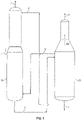
- A conventional process for separation of acrylonitrile from acetonitrile is shown in
FIG. 1 . As shown inFIG. 1 , feed stream 1 from an acrylonitrile absorber (not shown) is sent tofirst column 10. Feed stream 1 typically contains acrylonitrile, hydrogen cyanide (HCN), acetonitrile, and water. Water stream 2 that is substantially free of acetonitrile is recycled from at or near the bottom ofsecond column 20 to an upper portion offirst column 10 in order to facilitate the separation of acetonitrile from acrylonitrile and HCN by extractive distillation. Stream 3 containing acrylonitrile, HCN, and a portion of the water from feed 1 is removed from the top offirst column 10. Liquid stream 4 containing water and acetonitrile is sent as feed from the bottom offirst column 10 tosecond column 20. Vapor stream 5 fromsecond column 20 is sent tofirst column 10 to provide the heat needed for distillation infirst column 10.Vapor sidestream 4v moves up thesecond column 20 and includes acetonitrile. A crude acetonitrile stream 6 containing acetonitrile, water and small amounts of acrylonitrile and HCN is removed from the top ofsecond column 20. The remaining water stream 7, which is substantially free of acrylonitrile, HCN, and acetonitrile and is not recycled as water stream 2 back tofirst column 10, is discharged fromsecond column 20 at or near the bottom ofsecond column 20. - Another conventional process for separation of acrylonitrile from crude acetonitrile is shown in
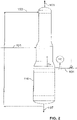
FIG. 2 . As shown inFIG. 2 ,feed stream 101 from an acrylonitrile absorber (not shown) is sent tocolumn 110.Feed stream 101 typically contains acrylonitrile, hydrogen cyanide (HCN), acetonitrile, and water.Bottoms stream 102 that is substantially free of acetonitrile is recycled from at or near the bottom ofcolumn 110 to the top ofcolumn 110 in order to facilitate the separation of acetonitrile from acrylonitrile and HCN by extractive distillation. The portion ofbottoms stream 102 that is not recycled to the top ofcolumn 110 is discharged fromcolumn 110 asstream 107.Overhead stream 103 containing acrylonitrile, HCN, and a portion of the water fromfeed stream 101 is removed from the top ofcolumn 110. Avapor sidestream 5v moves upcolumn 110 and a sidestream 104 (corresponding to 4v inFIG. 1 ) containing water and acetonitrile is removed fromcolumn 110. - Another example of a recovery column is shown in
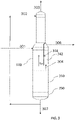
FIG. 3 . In this aspect, apparatus 300 includescolumn 310.Column 310 includes a top section 330, amiddle section 340, and abottom section 350.Middle section 340 of thesingle column 310 may be configured to receivefeed stream 301. In one aspect, the column includes a top section and a middle section and a ratio of a diameter of the middle section to the top section is about 0.8 to about 1.2, in another aspect about 0.9 to about 1.1, in another aspect about 1.5 to about 2.5, in another aspect, about 1.75 to about 2.25, and in another aspect, about 1.8 to about 2. In one aspect, the column includes a middle section and a bottom section and a ratio of a diameter of the bottom section to the middle section is about 0.8 to about 1.2, in another aspect about 0.9 to about 1.1, in another aspect about 1.5 to about 2.5, in another aspect, about 1.75 to about 2.25, and in another aspect, about 1.8 to about 2. In one aspect, the column includes a top section and a bottom section and a ratio of a diameter of the bottom section to the top section is about 0.8 to about 1.2, in another aspect about 0.9 to about 1.1, in another aspect about 1.5 to about 2.5, in another aspect, about 1.75 to about 2.25, and in another aspect, about 1.8 to about 2. In one aspect, the top section, middle section and bottom section are each about 25 to about 40% of a height (tangent to tangent) of the recovery column. - As shown in
FIG. 3 ,overhead stream 303 containing acrylonitrile, HCN and water is removed from the top ofcolumn 310. The recovery column may include a crudeacetonitrile concentration zone 342. The crudeacetonitrile concentration zone 342 includes internalvertical baffle 344. The crude acetonitrile concentration zone may include a plurality of trays. The trays are located at different heights of the column, and each tray includes a horizontal plane extending across a cross section of crudeacetonitrile concentration zone 342. Crudeacetonitrile concentration zone 342 includes an upper outlet configured to allowsidestream 306 to flow out ofcolumn 310 of crudeacetonitrile concentration zone 342. Vapor may flow up either side ofbaffle 344 asstream 304 or asvapor stream 5v. A portion of bottoms stream 302 that is not recycled to the top ofcolumn 310 is discharged asstream 307. - The recovery column includes a top section, middle section and bottom section. In one aspect, the top, middle and bottom sections are each about 25 to about 40% of a height (tangent to tangent) of the recovery column. Each recovery column section may be further divided into portions. For example, the middle section of the recovery column includes a top portion, middle portion and bottom portion. In this aspect, the top portion, middle portion and bottom portion are each about 25 to about 40 % of a height of the middle section of the recovery column. In another aspect, the top section of the recovery column includes a top portion and a bottom portion that are each about 40 to about 60% of a height of the top section of the recovery column. In another aspect, the bottom section of the recovery column includes a top portion and a bottom portion that are each about 40 to about 60% of a height of the bottom section of the recovery column.
- In another aspect, the recovery column may include about 80 to about 120 trays, and in another aspect, about 80 to about 100 trays. The plurality of trays in the recovery column includes a top section of trays, a middle section of trays, and a bottom section of trays. In this aspect, the top section of trays, middle section of trays and bottom section or trays are each about 25 to about 40% of a total number of trays in the recovery column.
- The top section of trays of the recovery column includes a top portion of trays and a bottom portion of trays that are each about 40 to about 60% of a total number of trays in the top section of trays in the recovery column. The middle section of trays includes a top portion of trays, middle portion of trays and bottom portion of trays. The top portion of trays, middle portion of trays and bottom portion of trays are each about 25 to about 40% of a total number of trays of the middle section of trays of the recovery column. The bottom section of trays of the recovery column includes a top portion of trays and a bottom portion of trays that are each about 40 to about 60% of a total number of trays in the bottom section of trays in the recovery column.
- A feed stream provided to the recovery column typically contains acrylonitrile, hydrogen cyanide (HCN), acetonitrile, and water (shown as feed stream 1 in
FIG. 1 , asfeed stream 101 inFIG. 2 , and asfeed stream 301 inFIG. 3 ). In this aspect, the feed stream provided to the recovery column includes about 2 to about 10 weight % acrylonitrile, in another aspect, about 3 to about 7 weight %, and in another aspect, about 4 to about 6 weight % acrylonitrile. The mixture also includes acetonitrile in an amount of about 0.1 to about 0.3 weight % acetonitrile, and in another aspect, about 0.15 to about 0.25 weight % acetonitrile. The mixture may also include other components, such as for example, acrolein and/or oxazole in smaller amounts. - Solvent water enters the recovery column at a top portion of the column (shown as water stream 2 in
FIG. 1 ,water stream 102 inFIG. 2 andwater stream 302 inFIG. 3 ). Solvent water which is introduced to the top of the recovery column flows down the tower across the trays, condensing and extracting acetonitrile as it travels to the bottom of the recovery column. As the liquid descends across the trays in the recovery column to the tower bottom, hot vapor from a stripper and heat from the live steam added, travel up the tower through the tray holes allowing intimate contact with the liquid on them. Heat transfer takes place between the liquid and vapor traffic and tends to move all the organics (except acetonitrile) up to the column top. - The overhead stream produced by the recovery column (shown as stream 3 in
FIG. 1 ,stream 103 inFIG. 2 , andstream 303 inFIG. 3 ) may include acrylonitrile, HCN, and a portion of the water from the feed stream. The recovery column may provide a vapor sidestream that includes water and acetonitrile that is substantially free of acrylonitrile and HCN (shown asstream 104 inFIG. 2 , and 304 inFIG. 3 ). The recovery column may also provide a bottoms stream (shown as bottoms stream 2 inFIG. 1 , bottoms stream 102 inFIG. 2 , and bottoms stream 302 inFIG. 3 ) which exits from a bottom portion of the recovery column. At least a portion of the bottoms stream may be recycled back to a top portion of the recovery column. Known methods for heating the recovery column include for example, steam, steam heated reboiler and/or heat exchange with other process streams. -
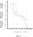
Figure 4 describes a temperature profile for recovery column operation. Proper temperature control and a temperature profile as described inFigure 4 are important for proper column operation. Variations within the temperature profile as defined by the dotted lines inFigure 4 can be effected by a combination of changes involving solvent water and feed temperatures, solvent water rate, and steam rate. Column pressure can also change the profile. - Changes above point "A" on the curve are predominantly due to variations in composition and pressure. Temperature variations above point "A" are not critical, but the overhead temperature should be kept as low as possible to minimize amounts of oxazole, acetonitrile, acetone and water going overhead. The temperature variations below point "B" are predominantly due to tray pressure changes, since the composition in this section is mostly water.
- Temperature control of the recovery column includes known temperature control systems that can include reboilers and heat exchangers. In one aspect, the heat duty required to produce the necessary boil-up in the bottom of the recovery column may be provided by heat transfer in any conventional reboiling apparatus. Conventional reboilers may include some variant of a shell-and-tube exchanger. Some examples of reboiler configurations include kettle, thermosyphon, forced circulation, stab-in bundle, horizontal, vertical and falling film. In one aspect, the process includes controlling temperature by removing liquid at or near the bottom of the recovery column and exchanging the liquid in a thermosiphon reboiler. In this aspect, the effluent from the thermosiphon reboiler is returned to the recovery column. Live steam may be injected either to supplement or to replace the required heat duty of the recovery column. In another aspect, the process includes reboiling of the recovery column through two vertical thermosyphon reboilers in parallel, using pressurized steam derived from turbine exhaust.
- In one aspect, recovery column temperature is maintained as follows:
- the top portion of the middle section of the recovery column is maintained at a temperature of about 65 to about 85 °C, and in another aspect, about 70 to about 80 °C;
- the bottom portion of the middle section of the recovery column is maintained at about 100 to about 120 °C, and in another aspect, about 105 to about 115 °C;
- the top portion of the top section of the recovery column is maintained at about 55 to about 80 °C, and in another aspect, about 60 to about 75 °C;
- the top portion and bottom portion of the top section of the recovery column have a temperature difference of about 0 to about 20 °C, and in another aspect, about 5 to about 15 °C;
- the bottom portion of the bottom section of the recovery column is maintained at about 105 to about 125 °C, and in another aspect, about 110 to about 120 °C; and
- the top portion and bottom portion of the bottom section of the recovery column have a temperature difference of about 0 to about 15 °C, and in another aspect, about 7 to about 13 °C.
- In another aspect, recovery column temperature is maintained as follows:
- the top portion of trays of the middle section of the recovery column is maintained at a temperature of about 65 to about 85 °C, and in another aspect, about 70 to about 80 °C;
- the bottom portion of trays of the middle section of the recovery column is maintained at about 100 to about 120 °C, and in another aspect, about 105 to about 115 °C;
- the top portion of trays of the top section of the recovery column is maintained at about 55 to about 80 °C, and in another aspect, about 60 to about 75 °C;
- the top portion of trays and bottom portion of trays of the top section of the recovery column have a temperature difference of about 0 to about 20 °C, and in another aspect, about 5 to about 15 °C;
- the bottom portion of trays of the bottom section of the recovery column is maintained at about 105 to about 125 °C, and in another aspect, about 110 to about 120 °C; and
- the top portion of trays and bottom portion of trays of the bottom section of the recovery column have a temperature difference of about 0 to about 15 °C, and in another aspect, about 7 to about 13 °C.
- In another aspect, temperature is controlled in the middle section of the recovery column as follows:
- in one aspect, a temperature drop in the middle section of the recovery column is about 35% or greater of a temperature drop from the top tray to the bottom tray of the recovery column;
- in another aspect, the temperature drop in the middle section of the recovery column is about 50% or greater of the temperature drop from the top tray to the bottom tray of the recovery column;
- in another aspect, the temperature drop in the middle section of the recovery column is about 75% or greater of the temperature drop from the top tray to the bottom tray of the recovery column;
- in another aspect, the temperature drop in the middle section of the recovery column is about 75% of the temperature drop from the top tray to the bottom tray of the recovery column; and
- in another aspect, the temperature drop in the middle section of the recovery column is about 80% of the temperature drop from the top tray to the bottom tray of the recovery column.
- Temperature control of the recovery column provides an overhead stream, bottoms stream and sidestream with the following compositions:
- an overhead stream that includes the acrylonitrile-water azeotrope and about 0.05 weight percent or less acetonitrile, in another aspect, about 0.03 weight percent or less acetonitrile, and in another aspect, about 0.01 weight percent or less acetonitrile;
- an overhead stream that includes about 70 weight percent to about 90 weight percent acrylonitrile, and in another aspect, about 75 to about 85 weight percent acrylonitrile;
- a bottoms stream that includes about 0 to about 0.0075 weight percent acetonitrile, in another aspect, about 0.0025 to about 0.007 weight percent acetonitrile, and in another aspect, about 0.0025 to about 0.005 weight percent acetonitrile; and
- a sidestream that includes about 5 to about 70 weight percent acetonitrile, in another aspect, about 5 to about 50 weight percent acetonitrile, and in another aspect, about 6 to about 12 weight percent acetonitrile.
- The process for operation of a recovery column comprises providing a temperature of 100 to 105 °C to a control tray in the recovery column prior to introduction of a feed stream into the recovery column. The control tray is located in a middle section of the recovery column. The process may further include providing a temperature of 100 °C or less in a top section of the recovery column prior to introduction of a feed stream into the recovery column. In another aspect, the top section of the recovery column is 70 to 90 °C prior to introduction of the feed stream into the recovery column.
- After providing the indicated temperatures, the process includes providing a mixture of acrylonitrile and acetonitrile to the middle section of the recovery column. The process includes contacting the mixture of acrylonitrile and acetonitrile with aqueous solvent to provide an acrylonitrile-water azeotrope; separating the acrylonitrile-water azeotrope from the acetonitrile to provide an overhead stream that includes the acrylonitrile-water azeotrope and about 0.05 weight percent or less acetonitrile. The process provides a bottoms stream that includes about 0 to about 0.0075 weight percent acetonitrile, and a sidestream that includes about 5 to about 70 weight % acetonitrile.
- In another aspect, the process for operation of a recovery column includes providing a temperature of 100 °C or less in a top section of the recovery column prior to introduction of a feed stream into the recovery column. Preferably the top section of the recovery column is 70 to 90 °C prior to introduction of a feed stream into the recovery column.
Claims (5)
- A process for operation of a recovery column, wherein acrylonitrile is separated from a mixture of acrylonitrile and acetonitrile provided to the recovery column, the process comprising providing a temperature of 100 to 105 °C to a control tray in the recovery column prior to introduction of a feed stream into the recovery column, wherein the control tray is located in the middle section of the recovery column, and further wherein the mixture of acrylonitrile and acetonitrile is provided to a middle section of the recovery column.
- The process of claim 1 further comprising providing a temperature of 100 °C or less in a top section of the recovery column prior to introduction of the feed stream into the recovery column.
- The process of claim 2 wherein the top section of the recovery column is 70 to 90 °C prior to introduction of the feed stream into the recovery column.
- The process of claim 1 wherein recovery column temperature control is provided with one or more reboilers and one or more heat exchangers.
- The process of claim 1 wherein an aqueous solvent is provided to a top section of the recovery column.
Applications Claiming Priority (2)
| Application Number | Priority Date | Filing Date | Title |
|---|---|---|---|
| CN201510947436.6A CN106892838A (en) | 2015-12-17 | 2015-12-17 | Recovery tower is controlled |
| PCT/US2016/063962 WO2017105820A1 (en) | 2015-12-17 | 2016-11-29 | Recovery column control |
Publications (2)
| Publication Number | Publication Date |
|---|---|
| EP3389810A1 EP3389810A1 (en) | 2018-10-24 |
| EP3389810B1 true EP3389810B1 (en) | 2022-03-30 |
Family
ID=57590838
Family Applications (1)
| Application Number | Title | Priority Date | Filing Date |
|---|---|---|---|
| EP16816502.5A Active EP3389810B1 (en) | 2015-12-17 | 2016-11-29 | Recovery column control |
Country Status (10)
| Country | Link |
|---|---|
| EP (1) | EP3389810B1 (en) |
| JP (1) | JP7003037B2 (en) |
| KR (1) | KR20180095026A (en) |
| CN (1) | CN106892838A (en) |
| ES (1) | ES2920858T3 (en) |
| HU (1) | HUE059006T2 (en) |
| RU (1) | RU2720939C2 (en) |
| SA (1) | SA518391822B1 (en) |
| TW (1) | TWI709552B (en) |
| WO (1) | WO2017105820A1 (en) |
Families Citing this family (2)
| Publication number | Priority date | Publication date | Assignee | Title |
|---|---|---|---|---|
| KR101605200B1 (en) | 2009-02-05 | 2016-03-22 | 엘에스전선 주식회사 | Cable Manufacturing Method and Cable Combination Method |
| KR101658232B1 (en) | 2009-11-03 | 2016-09-23 | 엘에스전선 주식회사 | Vertical Lay Up Machine with Back Twist Measurment Apparatus |
Family Cites Families (18)
| Publication number | Priority date | Publication date | Assignee | Title |
|---|---|---|---|---|
| US2415662A (en) * | 1943-10-06 | 1947-02-11 | Sinelair Refining Company | Distillation of acrylonitrile from acetonitrile |
| GB1051080A (en) | 1964-08-14 | |||
| FR1427860A (en) * | 1964-12-24 | 1966-02-11 | Electrochimie Soc | Improvements to the processes for obtaining pure acrylonitrile and acetonitrile |
| US3399120A (en) | 1965-12-09 | 1968-08-27 | Monsanto Co | Purification of olefinically unsaturated nitriles by water extractive distillation |
| US3936360A (en) | 1971-04-07 | 1976-02-03 | The Standard Oil Company | Process for distillation and recovery of olefinic nitriles |
| US4234510A (en) | 1973-06-07 | 1980-11-18 | Standard Oil Company | Recovery of acrylonitrile or methacrylonitrile by condensation |
| US3885928A (en) | 1973-06-18 | 1975-05-27 | Standard Oil Co Ohio | Acrylonitrile and methacrylonitrile recovery and purification system |
| CN1014888B (en) * | 1988-03-10 | 1991-11-27 | 中国石油化工总公司 | Recovery technique of acrylonitrile and acetonitrile |
| RU2024497C1 (en) * | 1991-06-28 | 1994-12-15 | Якушкин Михаил Иванович | Method of propionitrile synthesis |
| CN1059897C (en) * | 1997-11-13 | 2000-12-27 | 中国石油化工总公司 | Process for recovering and refining olefinic nitrile |
| WO2003031384A1 (en) * | 2001-10-09 | 2003-04-17 | Mitsubishi Chemical Corporation | Process for production of (meth)acrylic compounds and method of distillation |
| JP4034559B2 (en) | 2001-12-11 | 2008-01-16 | 三菱化学株式会社 | Distillation of (meth) acrylic acids |
| JP2007518736A (en) * | 2004-01-09 | 2007-07-12 | ザ・スタンダード・オイル・カンパニー | Method for purifying olefinically unsaturated nitriles |
| US20090299087A1 (en) * | 2008-05-28 | 2009-12-03 | Solutia, Inc. | Process for manufacturing unsaturated mononitriles to improve on-stream time and reduce fouling |
| JP5476774B2 (en) * | 2009-04-07 | 2014-04-23 | 三菱レイヨン株式会社 | Method for recovering (meth) acrylonitrile |
| CN104888489A (en) | 2014-03-06 | 2015-09-09 | 英尼奥斯欧洲股份公司 | Acrylonitrile product tower liquid level control method |
| CN104027994B (en) | 2014-05-30 | 2017-10-20 | 英尼奥斯欧洲股份公司 | The separation of crude acetonitrile and acrylonitrile |
| CN104107559A (en) * | 2014-06-11 | 2014-10-22 | 英尼奥斯欧洲股份公司 | Pollution reduction in acetonitrile removing step in acrylonitrile recovery |
-
2015
- 2015-12-17 CN CN201510947436.6A patent/CN106892838A/en active Pending
-
2016
- 2016-11-29 WO PCT/US2016/063962 patent/WO2017105820A1/en active Application Filing
- 2016-11-29 KR KR1020187020383A patent/KR20180095026A/en not_active Application Discontinuation
- 2016-11-29 RU RU2018124855A patent/RU2720939C2/en active
- 2016-11-29 JP JP2018531191A patent/JP7003037B2/en active Active
- 2016-11-29 ES ES16816502T patent/ES2920858T3/en active Active
- 2016-11-29 EP EP16816502.5A patent/EP3389810B1/en active Active
- 2016-11-29 HU HUE16816502A patent/HUE059006T2/en unknown
- 2016-12-01 TW TW105139717A patent/TWI709552B/en active
-
2018
- 2018-06-16 SA SA518391822A patent/SA518391822B1/en unknown
Non-Patent Citations (1)
| Title |
|---|
| GOEDECKE RALF ET AL: "Chapter 2: Verfahrensentwicklung", 19 June 2006, FLUIDVERFAHRENSTECHNIK : GRUNDLAGEN, METHODIK, TECHNIK, PRAXIS / HERAUSGEGEBEN VON, WILEY-VCH VERLAG GMBH & CO. KGAA, WEINHEIM, GERMANY, PAGE(S) 5 - 185, ISBN: 978-3-527-62364-8, XP009518422 * |
Also Published As
| Publication number | Publication date |
|---|---|
| TW201800387A (en) | 2018-01-01 |
| KR20180095026A (en) | 2018-08-24 |
| CN106892838A (en) | 2017-06-27 |
| SA518391822B1 (en) | 2022-04-07 |
| RU2720939C2 (en) | 2020-05-14 |
| EP3389810A1 (en) | 2018-10-24 |
| HUE059006T2 (en) | 2022-09-28 |
| RU2018124855A (en) | 2020-01-17 |
| JP2019500211A (en) | 2019-01-10 |
| ES2920858T3 (en) | 2022-08-10 |
| TWI709552B (en) | 2020-11-11 |
| JP7003037B2 (en) | 2022-01-20 |
| WO2017105820A1 (en) | 2017-06-22 |
| RU2018124855A3 (en) | 2020-01-17 |
Similar Documents
| Publication | Publication Date | Title |
|---|---|---|
| RU2736379C1 (en) | Purification method, method of producing and apparatus for distillation of acrylonitrile | |
| KR101648653B1 (en) | Method for purifying acetonitrile | |
| EA035520B1 (en) | Process and reactor for the epoxidation of propene | |
| KR20180101588A (en) | Purification of mercaptans or thiophenes using separation wall column distillation | |
| EP3389810B1 (en) | Recovery column control | |
| CN107941039B (en) | Quench tower aftercooler | |
| WO2015191528A1 (en) | Fouling reduction in the acetonitrile removal steps of acrylonitrile recovery | |
| JP7219252B2 (en) | Recovery tower control | |
| US4377444A (en) | Recovery and purification of olefinic nitriles | |
| US4276125A (en) | Process for purification of crude olefinically unsaturated nitrile and condenser useful for same process | |
| US20090299087A1 (en) | Process for manufacturing unsaturated mononitriles to improve on-stream time and reduce fouling | |
| WO2017105831A1 (en) | Recovery column for the purification of acrylonitrile/acetonitrile mixtures | |
| US7282600B2 (en) | Method for inhibiting polymerization during the recovery and purification of unsaturated mononitriles | |
| EP1419140B1 (en) | Improved operation of heads column in acrylonitrile production | |
| JP5785728B2 (en) | Unsaturated nitrile distillation method and distillation apparatus, and unsaturated nitrile production method |
Legal Events
| Date | Code | Title | Description |
|---|---|---|---|
| STAA | Information on the status of an ep patent application or granted ep patent |
Free format text: STATUS: UNKNOWN |
|
| STAA | Information on the status of an ep patent application or granted ep patent |
Free format text: STATUS: THE INTERNATIONAL PUBLICATION HAS BEEN MADE |
|
| PUAI | Public reference made under article 153(3) epc to a published international application that has entered the european phase |
Free format text: ORIGINAL CODE: 0009012 |
|
| STAA | Information on the status of an ep patent application or granted ep patent |
Free format text: STATUS: REQUEST FOR EXAMINATION WAS MADE |
|
| 17P | Request for examination filed |
Effective date: 20180621 |
|
| AK | Designated contracting states |
Kind code of ref document: A1 Designated state(s): AL AT BE BG CH CY CZ DE DK EE ES FI FR GB GR HR HU IE IS IT LI LT LU LV MC MK MT NL NO PL PT RO RS SE SI SK SM TR |
|
| AX | Request for extension of the european patent |
Extension state: BA ME |
|
| DAV | Request for validation of the european patent (deleted) | ||
| DAX | Request for extension of the european patent (deleted) | ||
| STAA | Information on the status of an ep patent application or granted ep patent |
Free format text: STATUS: EXAMINATION IS IN PROGRESS |
|
| 17Q | First examination report despatched |
Effective date: 20200129 |
|
| STAA | Information on the status of an ep patent application or granted ep patent |
Free format text: STATUS: EXAMINATION IS IN PROGRESS |
|
| GRAP | Despatch of communication of intention to grant a patent |
Free format text: ORIGINAL CODE: EPIDOSNIGR1 |
|
| STAA | Information on the status of an ep patent application or granted ep patent |
Free format text: STATUS: GRANT OF PATENT IS INTENDED |
|
| RIC1 | Information provided on ipc code assigned before grant |
Ipc: C07C 255/08 20060101ALI20211029BHEP Ipc: C07C 253/34 20060101ALI20211029BHEP Ipc: B01D 3/42 20060101ALI20211029BHEP Ipc: B01D 3/40 20060101AFI20211029BHEP |
|
| INTG | Intention to grant announced |
Effective date: 20211116 |
|
| RAP3 | Party data changed (applicant data changed or rights of an application transferred) |
Owner name: INEOS EUROPE AG |
|
| GRAS | Grant fee paid |
Free format text: ORIGINAL CODE: EPIDOSNIGR3 |
|
| GRAA | (expected) grant |
Free format text: ORIGINAL CODE: 0009210 |
|
| STAA | Information on the status of an ep patent application or granted ep patent |
Free format text: STATUS: THE PATENT HAS BEEN GRANTED |
|
| AK | Designated contracting states |
Kind code of ref document: B1 Designated state(s): AL AT BE BG CH CY CZ DE DK EE ES FI FR GB GR HR HU IE IS IT LI LT LU LV MC MK MT NL NO PL PT RO RS SE SI SK SM TR |
|
| REG | Reference to a national code |
Ref country code: GB Ref legal event code: FG4D |
|
| REG | Reference to a national code |
Ref country code: CH Ref legal event code: EP |
|
| REG | Reference to a national code |
Ref country code: AT Ref legal event code: REF Ref document number: 1478638 Country of ref document: AT Kind code of ref document: T Effective date: 20220415 |
|
| REG | Reference to a national code |
Ref country code: DE Ref legal event code: R096 Ref document number: 602016070567 Country of ref document: DE |
|
| REG | Reference to a national code |
Ref country code: IE Ref legal event code: FG4D |
|
| REG | Reference to a national code |
Ref country code: LT Ref legal event code: MG9D |
|
| REG | Reference to a national code |
Ref country code: NL Ref legal event code: FP |
|
| PG25 | Lapsed in a contracting state [announced via postgrant information from national office to epo] |
Ref country code: SE Free format text: LAPSE BECAUSE OF FAILURE TO SUBMIT A TRANSLATION OF THE DESCRIPTION OR TO PAY THE FEE WITHIN THE PRESCRIBED TIME-LIMIT Effective date: 20220330 Ref country code: RS Free format text: LAPSE BECAUSE OF FAILURE TO SUBMIT A TRANSLATION OF THE DESCRIPTION OR TO PAY THE FEE WITHIN THE PRESCRIBED TIME-LIMIT Effective date: 20220330 Ref country code: NO Free format text: LAPSE BECAUSE OF FAILURE TO SUBMIT A TRANSLATION OF THE DESCRIPTION OR TO PAY THE FEE WITHIN THE PRESCRIBED TIME-LIMIT Effective date: 20220630 Ref country code: LT Free format text: LAPSE BECAUSE OF FAILURE TO SUBMIT A TRANSLATION OF THE DESCRIPTION OR TO PAY THE FEE WITHIN THE PRESCRIBED TIME-LIMIT Effective date: 20220330 Ref country code: HR Free format text: LAPSE BECAUSE OF FAILURE TO SUBMIT A TRANSLATION OF THE DESCRIPTION OR TO PAY THE FEE WITHIN THE PRESCRIBED TIME-LIMIT Effective date: 20220330 Ref country code: BG Free format text: LAPSE BECAUSE OF FAILURE TO SUBMIT A TRANSLATION OF THE DESCRIPTION OR TO PAY THE FEE WITHIN THE PRESCRIBED TIME-LIMIT Effective date: 20220630 |
|
| REG | Reference to a national code |
Ref country code: ES Ref legal event code: FG2A Ref document number: 2920858 Country of ref document: ES Kind code of ref document: T3 Effective date: 20220810 |
|
| REG | Reference to a national code |
Ref country code: AT Ref legal event code: MK05 Ref document number: 1478638 Country of ref document: AT Kind code of ref document: T Effective date: 20220330 |
|
| PG25 | Lapsed in a contracting state [announced via postgrant information from national office to epo] |
Ref country code: LV Free format text: LAPSE BECAUSE OF FAILURE TO SUBMIT A TRANSLATION OF THE DESCRIPTION OR TO PAY THE FEE WITHIN THE PRESCRIBED TIME-LIMIT Effective date: 20220330 Ref country code: GR Free format text: LAPSE BECAUSE OF FAILURE TO SUBMIT A TRANSLATION OF THE DESCRIPTION OR TO PAY THE FEE WITHIN THE PRESCRIBED TIME-LIMIT Effective date: 20220701 Ref country code: FI Free format text: LAPSE BECAUSE OF FAILURE TO SUBMIT A TRANSLATION OF THE DESCRIPTION OR TO PAY THE FEE WITHIN THE PRESCRIBED TIME-LIMIT Effective date: 20220330 |
|
| REG | Reference to a national code |
Ref country code: HU Ref legal event code: AG4A Ref document number: E059006 Country of ref document: HU |
|
| PG25 | Lapsed in a contracting state [announced via postgrant information from national office to epo] |
Ref country code: SM Free format text: LAPSE BECAUSE OF FAILURE TO SUBMIT A TRANSLATION OF THE DESCRIPTION OR TO PAY THE FEE WITHIN THE PRESCRIBED TIME-LIMIT Effective date: 20220330 Ref country code: SK Free format text: LAPSE BECAUSE OF FAILURE TO SUBMIT A TRANSLATION OF THE DESCRIPTION OR TO PAY THE FEE WITHIN THE PRESCRIBED TIME-LIMIT Effective date: 20220330 Ref country code: RO Free format text: LAPSE BECAUSE OF FAILURE TO SUBMIT A TRANSLATION OF THE DESCRIPTION OR TO PAY THE FEE WITHIN THE PRESCRIBED TIME-LIMIT Effective date: 20220330 Ref country code: PT Free format text: LAPSE BECAUSE OF FAILURE TO SUBMIT A TRANSLATION OF THE DESCRIPTION OR TO PAY THE FEE WITHIN THE PRESCRIBED TIME-LIMIT Effective date: 20220801 Ref country code: EE Free format text: LAPSE BECAUSE OF FAILURE TO SUBMIT A TRANSLATION OF THE DESCRIPTION OR TO PAY THE FEE WITHIN THE PRESCRIBED TIME-LIMIT Effective date: 20220330 Ref country code: CZ Free format text: LAPSE BECAUSE OF FAILURE TO SUBMIT A TRANSLATION OF THE DESCRIPTION OR TO PAY THE FEE WITHIN THE PRESCRIBED TIME-LIMIT Effective date: 20220330 Ref country code: AT Free format text: LAPSE BECAUSE OF FAILURE TO SUBMIT A TRANSLATION OF THE DESCRIPTION OR TO PAY THE FEE WITHIN THE PRESCRIBED TIME-LIMIT Effective date: 20220330 |
|
| PG25 | Lapsed in a contracting state [announced via postgrant information from national office to epo] |
Ref country code: PL Free format text: LAPSE BECAUSE OF FAILURE TO SUBMIT A TRANSLATION OF THE DESCRIPTION OR TO PAY THE FEE WITHIN THE PRESCRIBED TIME-LIMIT Effective date: 20220330 Ref country code: IS Free format text: LAPSE BECAUSE OF FAILURE TO SUBMIT A TRANSLATION OF THE DESCRIPTION OR TO PAY THE FEE WITHIN THE PRESCRIBED TIME-LIMIT Effective date: 20220730 Ref country code: AL Free format text: LAPSE BECAUSE OF FAILURE TO SUBMIT A TRANSLATION OF THE DESCRIPTION OR TO PAY THE FEE WITHIN THE PRESCRIBED TIME-LIMIT Effective date: 20220330 |
|
| REG | Reference to a national code |
Ref country code: DE Ref legal event code: R097 Ref document number: 602016070567 Country of ref document: DE |
|
| PG25 | Lapsed in a contracting state [announced via postgrant information from national office to epo] |
Ref country code: DK Free format text: LAPSE BECAUSE OF FAILURE TO SUBMIT A TRANSLATION OF THE DESCRIPTION OR TO PAY THE FEE WITHIN THE PRESCRIBED TIME-LIMIT Effective date: 20220330 |
|
| PGFP | Annual fee paid to national office [announced via postgrant information from national office to epo] |
Ref country code: TR Payment date: 20221124 Year of fee payment: 7 Ref country code: NL Payment date: 20221126 Year of fee payment: 7 Ref country code: IT Payment date: 20221123 Year of fee payment: 7 Ref country code: GB Payment date: 20221128 Year of fee payment: 7 Ref country code: FR Payment date: 20221123 Year of fee payment: 7 Ref country code: ES Payment date: 20221201 Year of fee payment: 7 Ref country code: DE Payment date: 20221125 Year of fee payment: 7 |
|
| PLBE | No opposition filed within time limit |
Free format text: ORIGINAL CODE: 0009261 |
|
| STAA | Information on the status of an ep patent application or granted ep patent |
Free format text: STATUS: NO OPPOSITION FILED WITHIN TIME LIMIT |
|
| PGFP | Annual fee paid to national office [announced via postgrant information from national office to epo] |
Ref country code: HU Payment date: 20221109 Year of fee payment: 7 Ref country code: BE Payment date: 20221128 Year of fee payment: 7 |
|
| 26N | No opposition filed |
Effective date: 20230103 |
|
| PG25 | Lapsed in a contracting state [announced via postgrant information from national office to epo] |
Ref country code: SI Free format text: LAPSE BECAUSE OF FAILURE TO SUBMIT A TRANSLATION OF THE DESCRIPTION OR TO PAY THE FEE WITHIN THE PRESCRIBED TIME-LIMIT Effective date: 20220330 |
|
| PG25 | Lapsed in a contracting state [announced via postgrant information from national office to epo] |
Ref country code: MC Free format text: LAPSE BECAUSE OF FAILURE TO SUBMIT A TRANSLATION OF THE DESCRIPTION OR TO PAY THE FEE WITHIN THE PRESCRIBED TIME-LIMIT Effective date: 20220330 |
|
| REG | Reference to a national code |
Ref country code: CH Ref legal event code: PL |
|
| P01 | Opt-out of the competence of the unified patent court (upc) registered |
Effective date: 20230530 |
|
| PG25 | Lapsed in a contracting state [announced via postgrant information from national office to epo] |
Ref country code: LI Free format text: LAPSE BECAUSE OF NON-PAYMENT OF DUE FEES Effective date: 20221130 Ref country code: CH Free format text: LAPSE BECAUSE OF NON-PAYMENT OF DUE FEES Effective date: 20221130 |
|
| PG25 | Lapsed in a contracting state [announced via postgrant information from national office to epo] |
Ref country code: LU Free format text: LAPSE BECAUSE OF NON-PAYMENT OF DUE FEES Effective date: 20221129 |
|
| PG25 | Lapsed in a contracting state [announced via postgrant information from national office to epo] |
Ref country code: IE Free format text: LAPSE BECAUSE OF NON-PAYMENT OF DUE FEES Effective date: 20221129 |