EP3389538B1 - Medizinische instrumentenverfolgung - Google Patents
Medizinische instrumentenverfolgung Download PDFInfo
- Publication number
- EP3389538B1 EP3389538B1 EP16816652.8A EP16816652A EP3389538B1 EP 3389538 B1 EP3389538 B1 EP 3389538B1 EP 16816652 A EP16816652 A EP 16816652A EP 3389538 B1 EP3389538 B1 EP 3389538B1
- Authority
- EP
- European Patent Office
- Prior art keywords
- instrument
- marker
- medical instrument
- tracking
- tip
- Prior art date
- Legal status (The legal status is an assumption and is not a legal conclusion. Google has not performed a legal analysis and makes no representation as to the accuracy of the status listed.)
- Active
Links
- 239000003550 marker Substances 0.000 claims description 96
- 238000000034 method Methods 0.000 claims description 28
- 238000004590 computer program Methods 0.000 claims description 17
- 230000003287 optical effect Effects 0.000 claims description 14
- 239000003973 paint Substances 0.000 claims description 14
- 239000000463 material Substances 0.000 claims description 12
- 239000002390 adhesive tape Substances 0.000 claims description 5
- 230000004044 response Effects 0.000 claims description 4
- FGUUSXIOTUKUDN-IBGZPJMESA-N C1(=CC=CC=C1)N1C2=C(NC([C@H](C1)NC=1OC(=NN=1)C1=CC=CC=C1)=O)C=CC=C2 Chemical compound C1(=CC=CC=C1)N1C2=C(NC([C@H](C1)NC=1OC(=NN=1)C1=CC=CC=C1)=O)C=CC=C2 FGUUSXIOTUKUDN-IBGZPJMESA-N 0.000 claims description 3
- 239000011248 coating agent Substances 0.000 description 3
- 238000000576 coating method Methods 0.000 description 3
- 230000001419 dependent effect Effects 0.000 description 3
- 239000000975 dye Substances 0.000 description 3
- 238000002059 diagnostic imaging Methods 0.000 description 2
- MOFVSTNWEDAEEK-UHFFFAOYSA-M indocyanine green Chemical compound [Na+].[O-]S(=O)(=O)CCCCN1C2=CC=C3C=CC=CC3=C2C(C)(C)C1=CC=CC=CC=CC1=[N+](CCCCS([O-])(=O)=O)C2=CC=C(C=CC=C3)C3=C2C1(C)C MOFVSTNWEDAEEK-UHFFFAOYSA-M 0.000 description 2
- 229960004657 indocyanine green Drugs 0.000 description 2
- 230000003993 interaction Effects 0.000 description 2
- 238000005259 measurement Methods 0.000 description 2
- 238000001356 surgical procedure Methods 0.000 description 2
- 230000003936 working memory Effects 0.000 description 2
- RBTBFTRPCNLSDE-UHFFFAOYSA-N 3,7-bis(dimethylamino)phenothiazin-5-ium Chemical compound C1=CC(N(C)C)=CC2=[S+]C3=CC(N(C)C)=CC=C3N=C21 RBTBFTRPCNLSDE-UHFFFAOYSA-N 0.000 description 1
- 206010028980 Neoplasm Diseases 0.000 description 1
- SJEYSFABYSGQBG-UHFFFAOYSA-M Patent blue Chemical compound [Na+].C1=CC(N(CC)CC)=CC=C1C(C=1C(=CC(=CC=1)S([O-])(=O)=O)S([O-])(=O)=O)=C1C=CC(=[N+](CC)CC)C=C1 SJEYSFABYSGQBG-UHFFFAOYSA-M 0.000 description 1
- 239000002253 acid Substances 0.000 description 1
- 238000004164 analytical calibration Methods 0.000 description 1
- 238000002583 angiography Methods 0.000 description 1
- 210000001367 artery Anatomy 0.000 description 1
- 230000003190 augmentative effect Effects 0.000 description 1
- 230000008901 benefit Effects 0.000 description 1
- 238000002591 computed tomography Methods 0.000 description 1
- 238000010276 construction Methods 0.000 description 1
- 238000003745 diagnosis Methods 0.000 description 1
- 230000000694 effects Effects 0.000 description 1
- 230000005284 excitation Effects 0.000 description 1
- GNBHRKFJIUUOQI-UHFFFAOYSA-N fluorescein Chemical compound O1C(=O)C2=CC=CC=C2C21C1=CC=C(O)C=C1OC1=CC(O)=CC=C21 GNBHRKFJIUUOQI-UHFFFAOYSA-N 0.000 description 1
- 239000007850 fluorescent dye Substances 0.000 description 1
- 230000006870 function Effects 0.000 description 1
- 238000013152 interventional procedure Methods 0.000 description 1
- 238000012977 invasive surgical procedure Methods 0.000 description 1
- 229960000907 methylthioninium chloride Drugs 0.000 description 1
- 238000002324 minimally invasive surgery Methods 0.000 description 1
- 210000005036 nerve Anatomy 0.000 description 1
- 238000003909 pattern recognition Methods 0.000 description 1
- 229940109328 photofrin Drugs 0.000 description 1
- 229920002379 silicone rubber Polymers 0.000 description 1
- 239000004945 silicone rubber Substances 0.000 description 1
- 239000007787 solid Substances 0.000 description 1
- 238000011477 surgical intervention Methods 0.000 description 1
- 230000002195 synergetic effect Effects 0.000 description 1
- 230000007704 transition Effects 0.000 description 1
- 230000000007 visual effect Effects 0.000 description 1
Images

Classifications
-
- A—HUMAN NECESSITIES
- A61—MEDICAL OR VETERINARY SCIENCE; HYGIENE
- A61B—DIAGNOSIS; SURGERY; IDENTIFICATION
- A61B34/00—Computer-aided surgery; Manipulators or robots specially adapted for use in surgery
- A61B34/20—Surgical navigation systems; Devices for tracking or guiding surgical instruments, e.g. for frameless stereotaxis
-
- A—HUMAN NECESSITIES
- A61—MEDICAL OR VETERINARY SCIENCE; HYGIENE
- A61B—DIAGNOSIS; SURGERY; IDENTIFICATION
- A61B90/00—Instruments, implements or accessories specially adapted for surgery or diagnosis and not covered by any of the groups A61B1/00 - A61B50/00, e.g. for luxation treatment or for protecting wound edges
- A61B90/90—Identification means for patients or instruments, e.g. tags
- A61B90/92—Identification means for patients or instruments, e.g. tags coded with colour
-
- A—HUMAN NECESSITIES
- A61—MEDICAL OR VETERINARY SCIENCE; HYGIENE
- A61B—DIAGNOSIS; SURGERY; IDENTIFICATION
- A61B90/00—Instruments, implements or accessories specially adapted for surgery or diagnosis and not covered by any of the groups A61B1/00 - A61B50/00, e.g. for luxation treatment or for protecting wound edges
- A61B90/90—Identification means for patients or instruments, e.g. tags
- A61B90/94—Identification means for patients or instruments, e.g. tags coded with symbols, e.g. text
- A61B90/96—Identification means for patients or instruments, e.g. tags coded with symbols, e.g. text using barcodes
-
- G—PHYSICS
- G06—COMPUTING; CALCULATING OR COUNTING
- G06T—IMAGE DATA PROCESSING OR GENERATION, IN GENERAL
- G06T7/00—Image analysis
- G06T7/20—Analysis of motion
- G06T7/246—Analysis of motion using feature-based methods, e.g. the tracking of corners or segments
-
- G—PHYSICS
- G06—COMPUTING; CALCULATING OR COUNTING
- G06T—IMAGE DATA PROCESSING OR GENERATION, IN GENERAL
- G06T7/00—Image analysis
- G06T7/20—Analysis of motion
- G06T7/246—Analysis of motion using feature-based methods, e.g. the tracking of corners or segments
- G06T7/248—Analysis of motion using feature-based methods, e.g. the tracking of corners or segments involving reference images or patches
-
- G—PHYSICS
- G06—COMPUTING; CALCULATING OR COUNTING
- G06T—IMAGE DATA PROCESSING OR GENERATION, IN GENERAL
- G06T7/00—Image analysis
- G06T7/20—Analysis of motion
- G06T7/292—Multi-camera tracking
-
- G—PHYSICS
- G06—COMPUTING; CALCULATING OR COUNTING
- G06T—IMAGE DATA PROCESSING OR GENERATION, IN GENERAL
- G06T7/00—Image analysis
- G06T7/70—Determining position or orientation of objects or cameras
- G06T7/73—Determining position or orientation of objects or cameras using feature-based methods
-
- G—PHYSICS
- G06—COMPUTING; CALCULATING OR COUNTING
- G06V—IMAGE OR VIDEO RECOGNITION OR UNDERSTANDING
- G06V10/00—Arrangements for image or video recognition or understanding
- G06V10/40—Extraction of image or video features
-
- G—PHYSICS
- G06—COMPUTING; CALCULATING OR COUNTING
- G06V—IMAGE OR VIDEO RECOGNITION OR UNDERSTANDING
- G06V20/00—Scenes; Scene-specific elements
- G06V20/20—Scenes; Scene-specific elements in augmented reality scenes
-
- G—PHYSICS
- G06—COMPUTING; CALCULATING OR COUNTING
- G06V—IMAGE OR VIDEO RECOGNITION OR UNDERSTANDING
- G06V20/00—Scenes; Scene-specific elements
- G06V20/60—Type of objects
- G06V20/64—Three-dimensional objects
-
- G—PHYSICS
- G06—COMPUTING; CALCULATING OR COUNTING
- G06V—IMAGE OR VIDEO RECOGNITION OR UNDERSTANDING
- G06V40/00—Recognition of biometric, human-related or animal-related patterns in image or video data
- G06V40/10—Human or animal bodies, e.g. vehicle occupants or pedestrians; Body parts, e.g. hands
- G06V40/16—Human faces, e.g. facial parts, sketches or expressions
-
- G—PHYSICS
- G06—COMPUTING; CALCULATING OR COUNTING
- G06V—IMAGE OR VIDEO RECOGNITION OR UNDERSTANDING
- G06V40/00—Recognition of biometric, human-related or animal-related patterns in image or video data
- G06V40/10—Human or animal bodies, e.g. vehicle occupants or pedestrians; Body parts, e.g. hands
- G06V40/18—Eye characteristics, e.g. of the iris
- G06V40/19—Sensors therefor
-
- A—HUMAN NECESSITIES
- A61—MEDICAL OR VETERINARY SCIENCE; HYGIENE
- A61B—DIAGNOSIS; SURGERY; IDENTIFICATION
- A61B17/00—Surgical instruments, devices or methods, e.g. tourniquets
- A61B2017/00681—Aspects not otherwise provided for
- A61B2017/00725—Calibration or performance testing
-
- A—HUMAN NECESSITIES
- A61—MEDICAL OR VETERINARY SCIENCE; HYGIENE
- A61B—DIAGNOSIS; SURGERY; IDENTIFICATION
- A61B34/00—Computer-aided surgery; Manipulators or robots specially adapted for use in surgery
- A61B34/10—Computer-aided planning, simulation or modelling of surgical operations
- A61B2034/101—Computer-aided simulation of surgical operations
- A61B2034/102—Modelling of surgical devices, implants or prosthesis
-
- A—HUMAN NECESSITIES
- A61—MEDICAL OR VETERINARY SCIENCE; HYGIENE
- A61B—DIAGNOSIS; SURGERY; IDENTIFICATION
- A61B34/00—Computer-aided surgery; Manipulators or robots specially adapted for use in surgery
- A61B34/20—Surgical navigation systems; Devices for tracking or guiding surgical instruments, e.g. for frameless stereotaxis
- A61B2034/2046—Tracking techniques
- A61B2034/2055—Optical tracking systems
-
- A—HUMAN NECESSITIES
- A61—MEDICAL OR VETERINARY SCIENCE; HYGIENE
- A61B—DIAGNOSIS; SURGERY; IDENTIFICATION
- A61B34/00—Computer-aided surgery; Manipulators or robots specially adapted for use in surgery
- A61B34/20—Surgical navigation systems; Devices for tracking or guiding surgical instruments, e.g. for frameless stereotaxis
- A61B2034/2046—Tracking techniques
- A61B2034/2065—Tracking using image or pattern recognition
-
- A—HUMAN NECESSITIES
- A61—MEDICAL OR VETERINARY SCIENCE; HYGIENE
- A61B—DIAGNOSIS; SURGERY; IDENTIFICATION
- A61B90/00—Instruments, implements or accessories specially adapted for surgery or diagnosis and not covered by any of the groups A61B1/00 - A61B50/00, e.g. for luxation treatment or for protecting wound edges
- A61B90/36—Image-producing devices or illumination devices not otherwise provided for
- A61B90/37—Surgical systems with images on a monitor during operation
- A61B2090/371—Surgical systems with images on a monitor during operation with simultaneous use of two cameras
-
- A—HUMAN NECESSITIES
- A61—MEDICAL OR VETERINARY SCIENCE; HYGIENE
- A61B—DIAGNOSIS; SURGERY; IDENTIFICATION
- A61B90/00—Instruments, implements or accessories specially adapted for surgery or diagnosis and not covered by any of the groups A61B1/00 - A61B50/00, e.g. for luxation treatment or for protecting wound edges
- A61B90/39—Markers, e.g. radio-opaque or breast lesions markers
- A61B2090/3937—Visible markers
- A61B2090/3941—Photoluminescent markers
-
- A—HUMAN NECESSITIES
- A61—MEDICAL OR VETERINARY SCIENCE; HYGIENE
- A61B—DIAGNOSIS; SURGERY; IDENTIFICATION
- A61B90/00—Instruments, implements or accessories specially adapted for surgery or diagnosis and not covered by any of the groups A61B1/00 - A61B50/00, e.g. for luxation treatment or for protecting wound edges
- A61B90/39—Markers, e.g. radio-opaque or breast lesions markers
- A61B2090/3983—Reference marker arrangements for use with image guided surgery
-
- G—PHYSICS
- G06—COMPUTING; CALCULATING OR COUNTING
- G06T—IMAGE DATA PROCESSING OR GENERATION, IN GENERAL
- G06T2207/00—Indexing scheme for image analysis or image enhancement
- G06T2207/10—Image acquisition modality
- G06T2207/10116—X-ray image
-
- G—PHYSICS
- G06—COMPUTING; CALCULATING OR COUNTING
- G06T—IMAGE DATA PROCESSING OR GENERATION, IN GENERAL
- G06T2207/00—Indexing scheme for image analysis or image enhancement
- G06T2207/20—Special algorithmic details
- G06T2207/20048—Transform domain processing
- G06T2207/20061—Hough transform
-
- G—PHYSICS
- G06—COMPUTING; CALCULATING OR COUNTING
- G06T—IMAGE DATA PROCESSING OR GENERATION, IN GENERAL
- G06T2207/00—Indexing scheme for image analysis or image enhancement
- G06T2207/30—Subject of image; Context of image processing
- G06T2207/30204—Marker
Definitions
- the present invention relates to the field of medical instrument tracking, and in particular to a system for tracking a medical instrument, to a method for tracking a medical instrument, to a computer program element, and to a computer readable medium.
- Medical instruments such as steerable devices, flexible catheters or more rigid arms or shafts, are used in minimally invasive procedures for diagnosis and treatment of medical conditions.
- WO 2015/032676 A1 describes electromagnetic tracking sensors for determining the position and shape of an interventional device.
- Some tracking methods may require the information about the dimensions of the medical instruments, which may be stored in a database.
- US 2012/0259204 A1 describes providing an instrument with visibility elements along an axis, whereby positions of the elements characterizing a specific instrument are stored in a database.
- WO-A-9938449 discloses a tracking arrangement and a processing unit; wherein the tracking arrangement is configured to obtain images of the medical instrument, the images including an instrument marker located on the medical instrument at a marker position remote from a tip of the medical instrument, and wherein the processing unit is configured to detect line segments and the instrument marker in the obtained images and to determine an offset of a position of the tip of the medical instrument based on the medical instrument touching a reference marker.
- a system for tracking an elongated medical instrument in a field of interest comprises a tracking arrangement and a processing unit.
- the tracking arrangement is configured to obtain images of the medical instrument, the images including an instrument marker located on the medical instrument at a marker position remote from a tip of the medical instrument.
- the processing unit is configured to i) detect at least one line segment and the instrument marker in the obtained images; ii) identify the medical instrument by selecting, from the at least one line segment detected, a line segment corresponding to the detected instrument marker; and iii) to determine an offset of a position of the tip of the medical instrument based on a the medical instrument touching a reference marker.
- a straight and elongated medical instrument is used.
- the instrument marker may be used as a reference.
- an offset between the marker and the tip position may be determined.
- a reference marker on the subject may be touched by the instrument tip.
- the touching of a reference marker by the instrument tip may be detected through the tracking arrangement. For instance, when the reference marker is visible in the images provided by the tracking arrangement, a touching between the instrument tip and the medical instrument may be detected from the images provided.
- “touching” shall be understood as not merely physically touching, but also virtually touching, that is, bringing the medical instrument sufficiently close to the reference marker, so that in one or more of the tracking images the instrument and marker representations overlap.
- a touching may be detected even when the position of the tip of the instrument itself cannot be established in the tracking image with sufficient reliability.
- At least one reference marker is provided on the subject.
- a set of reference markers may be provided on the exterior of a patient.
- the tracking arrangement may track patient movements in addition to tracking the instrument position.
- instrument marker located on the medical instrument may include that the instrument marker is a separate marker attached to the medical instrument and that the instrument marker is an integral part of the medical instrument.
- a single instrument marker may be sufficient to track the medical instrument.
- the offset between a single marker and the instrument tip by be determined reliably by means of a touch interaction between the instrument tip and the reference marker.
- the instrument marker comprises at least one of the group of: a biocompatible reflective paint, a fluorescent paint, a material with intrinsic reflective response for forming the medical instrument, and a self-adhesive tape.
- the instrument markers may be attached or sprayed on the medical instrument.
- the biocompatible reflective paint and/or the fluorescent paint has emission of light that is bandwidth selective.
- excitation/emission of the reflective or fluorescent paint maybe bandwidth selective such that a filtered light source and/camera is used for position determination while the video image of the scene remains undisturbed.
- a landmark of the instrument itself may be used as an instrument marker.
- a boundary between two portions of the instrument may be used as an instrument marker. For instance, a boundary between a shaft and a handle portion of an instrument, which boundary is perpendicular to the shaft direction, may be visible sufficiently clearly in the tracking images to enable instrument tracking. By detecting such transition, it may become possible to track the instrument without attaching a separate (artificial) marker to the device.
- an optical tracking arrangement having at least one camera is employed.
- a 3D position of the medical instrument may be determined by using images from the at least one camera.
- at least two optical cameras are used in order to enable accurate 3D tracking.
- a single depth resolving camera may be employed that generates optical images enhanced with depth measurements as an input for 3D tracking.
- a 3D model of the medical instrument by using the at least two cameras and a light source.
- the cameras and the light source may have specific wavelength filters suitable for the type of reflective materials used.
- One or more instruments used in the procedure can be identified by using different reflective materials and using filter sets of specific wavelength.
- a method for tracking a medical instrument in a field of interest comprises the following steps:
- Fig. 1 schematically shows a system 100 for tracking a medical instrument 10 in a field of interest 12.
- the system 100 comprises a tracking arrangement 16, and a processing unit 18. To enable its tracking, an instrument marker 14 is located on the medical instrument 10 on a marker position 20.
- field of interest may relate to a field in which the medical instrument is used, such as a surgical field, a field of operation, etc.
- medical instrument may relate to a specially designed tool or device for performing specific actions of carrying out desired effects during a surgery or operation, such as modifying biological tissues.
- the medical instrument 10 may comprise an instrument shaft 30, which is straight and elongated, and a handle 38.
- An instrument marker 14 is attached on the instrument shaft 30 away from a medical instrument tip 28.
- a boundary between the shaft 30 and the handle 38 may be used as an instrument marker 14'.
- the instrument marker 14, 14' can provide a reference for indicating the position of the medical instrument tip 28.
- the instrument marker 14 comprises at least one of the group of: a biocompatible reflective paint, a fluorescent paint, a material with intrinsic reflective response for forming a part of the medical instrument, and a self-adhesive tape.
- Fluorescence dyes similar to those used in tumor surgeries may be used as a fluorescent paint, which should be biocompatible.
- fluorescence dyes include indocyanine green (ICG), fluorescein, photofrin, 5-aminolevullinic acid (ALA), patent blue, methylene blue, etc.
- the biocompatible reflective paint or the fluorescent paint may be coated or sprayed on the medical instrument, such as surgical or laparoscopic instruments in use, e.g. during the minimal invasive surgical procedure.
- Reflective or fluorescent dye coating may be reapplied after several usages based on the efficiency of the dye or coating material.
- Coating material can be autoclavable or sterilisable for repeated usage.
- a part of the medical instrument for example a portion of the shaft 30, may be made of a material that has intrinsic reflective or fluorescent response.
- a part of the medical instrument may be used as an instrument marker for indicating the position of the medical instrument tip 28.
- the instrument marker 14 is a piece of self-adhesive tape, which can be wrapped around e.g. a central axis of the medical instrument until it is securely fastened.
- the self-adhesive tape may be constructed from materials including for example a silicone rubber sleeve that is slid over e.g. the medical instrument shaft, heat-shrink tubing, or a permanently painted, etched or engraved marker.
- the above-mentioned instrument markers may optionally have a pattern extending in a direction for encircling the medical instrument.
- the instrument marker 14 has a pattern of lines.
- the pattern of lines such as the number of lines and/or the thickness of the lines, may be varied to distinguish between different medical instruments.
- the medical instruments with the same pattern may be distinguished between each other by using e.g. the thickness of the medical instrument shaft.
- the medical instrument may be detected or tracked in all directions.
- the medical instrument 10 is tracked by the tracking arrangement 16.
- the tracking arrangement 16 may be an optical tracking arrangement, an ultrasonic tracking arrangement, or any other suitable tracking arrangement.
- the tracking arrangement 16 is an optical tracking arrangement comprising at least two optical sensors 32, such as two cameras as shown in Fig. 1 , which allows for multiple medical instruments to be tracked simultaneously.
- the position and orientation of the optical sensors 32 relative to each other may be known, e.g. via rigid mechanical construction.
- an optical tracking arrangement may comprise a depth resolving camera providing optical images together with depth measurements.
- the optical sensors may be supported in a determined spatial relationship to an X-ray device in a medical imaging system, as has been described in WO 2010/067281 A1 .
- the optical sensors 32 may comprise a wavelength filter suitable for the type of reflective or fluorescent materials used.
- One of more medical instruments used in the procedure may be identified by using different reflective materials and using filter sets of specific wavelengths.
- the tracking system 16 may be integrated into a surgical set up either as a part of a medical imaging system (e.g. a C-arm X-ray system as stated above) or as a separate tracking unit.
- a medical imaging system e.g. a C-arm X-ray system as stated above
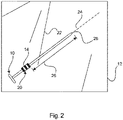
- Fig. 2 schematically shows an example of the field of interest 12 with the medical instrument 10 inside.
- the tracking system 100 is configured to detect line segments 22 (indicated with solid lines) in the field of interest 12 and to detect the instrument marker 14, or marker 14' as indicated in Fig. 1 .
- the processing unit 18 is configured to select a line segment 24 (indicated with a dashed line) corresponding to the detected instrument marker, as the medical instrument 10, and to use the marker position 20 as a reference to determine an offset 26 of a tip position of the medical instrument tip 28.
- offset relates to a spatial distance
- the tip position of the medical instrument may include possible extensions of the medical instrument, such as the length of a (rigidly) connected part, e.g. a pedicle screw attached to a screwdriver.
- a (rigidly) connected part e.g. a pedicle screw attached to a screwdriver.
- the tracking system 16 images the field of interest 12 and acquires image data of the field of interest 12.
- the images may be corrected for lens distortion, so that straight lines in real world are visible as straight lines in the images. However, if low-distortion lenses are used, this step could be omitted.
- the processing unit 18 is configured to detect straight lines in the acquired image data, e.g. via Hough transform.
- the processing unit 18 is further configured to determine endpoints of each of the detected straight lines. For each detected straight line, a plane spanning the line end points and the camera center may be stored.
- the processing unit 18 is further configured to determine an intersection of each pair of planes for each detected straight lines. This yields a 3D line description with a start and endpoint.
- the instrument marker 14 is detected on at least one camera image e.g. with pattern recognition.
- the straight line, on which the attached instrument marker 14 is detected, can be identified as the medical instrument and can be tracked.
- the reference marker 34 is typically a marker, within or close to the field of interest, which is used to track patient motion.
- the reference marker 34 is provided to be touched by the medical instrument tip 28 and is visible in the images obtained by the tracking arrangement.
- the reference marker 34 may for example have a circular shape, however different shapes may be used in order to more reliably establish a touching of the marker 34 by the medical instrument tip 28.
- the marker 34 shown in Fig. 1 has a circular body from which a tail portion extends, to further improve visibility of the marker 34 in the tracking images when an instrument 10 is adjacent to the marker.
- the processing unit may further be configured to detect the distance between the instrument marker 14 and the touched reference marker 34 along the selected line segment 24, and to use the detected distance as input for determine the an offset 26 between marker 14 and tip position 28.
- the tracking arrangement 16 is configured to acquire image data of the field of interest 12.
- the processing unit 18 is configured to generate a 3D model from the acquired image data and to calculate the offset 26 to the tip position based on the marker position 20.
- the tracking images may be made visible to a user on a display screen.
- feedback on a touch interaction between the instrument tip 28 and the reference marker 34 may be given in an augmented reality view.
- a user can be given visual feedback that the instrument calibration has been established successfully, in other words that the tip offset has been determined. Based on this, the user may subsequently initiate an interventional procedure in which the instrument tip is inserted into the subject.
- a virtual instrument (not shown) may be displayed on patient data using the saved distance between the instrument marker 14 and the tip position 28 along the line segment.
- the patient data may be a 3D tomographic data set, which is registered prior to the minimal invasive intervention.
- the 3D tomographic data set may be e.g. a CT/MR (computed tomography/ magnetic resonance) dataset or an XperCT/VasoCT/angiography dataset.
- the patient data may be live X-ray data which may be shown to a user in addition to one or more of the tracking camera images
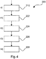
- Fig. 3 shows basic steps of an example of a method 200 for tracking an instrument. The method comprises the following steps:
- step f) of the method 200 further comprises the following sub-steps: f1) providing 222 a reference marker; f2) using 224 the medical instrument tip to touch the reference marker; f3) detecting 226 a distance between the instrument marker and the touched reference marker along the selected line segment and f4) using 228 the detected distance as the offset.
- a computer program or a computer program element is provided that is characterized by being adapted to execute the method steps of the method according to one of the preceding embodiments, on an appropriate system.
- the computer program element might therefore be stored on a computer unit, which might also be part of an embodiment of the present invention.
- This computing unit may be adapted to perform or induce a performing of the steps of the method described above. Moreover, it may be adapted to operate the components of the above described apparatus.
- the computing unit can be adapted to operate automatically and/or to execute the orders of a user.
- a computer program may be loaded into a working memory of a data processor.
- the data processor may thus be equipped to carry out the method of the invention.
- This exemplary embodiment of the invention covers both, a computer program that right from the beginning uses the invention and a computer program that by means of an up-date turns an existing program into a program that uses the invention.
- the computer program element might be able to provide all necessary steps to fulfil the procedure of an exemplary embodiment of the method as described above.
- a computer readable medium such as a CD-ROM
- the computer readable medium has a computer program element stored on it which computer program element is described by the preceding section.
- a computer program may be stored and/or distributed on a suitable medium, such as an optical storage medium or a solid state medium supplied together with or as part of other hardware, but may also be distributed in other forms, such as via the internet or other wired or wireless telecommunication systems.
- a suitable medium such as an optical storage medium or a solid state medium supplied together with or as part of other hardware, but may also be distributed in other forms, such as via the internet or other wired or wireless telecommunication systems.
- the computer program may also be presented over a network like the World Wide Web and can be downloaded into the working memory of a data processor from such a network.
- a medium for making a computer program element available for downloading is provided, which computer program element is arranged to perform a method according to one of the previously described embodiments of the invention.
Landscapes
- Engineering & Computer Science (AREA)
- Health & Medical Sciences (AREA)
- General Physics & Mathematics (AREA)
- Theoretical Computer Science (AREA)
- Physics & Mathematics (AREA)
- Multimedia (AREA)
- Surgery (AREA)
- Life Sciences & Earth Sciences (AREA)
- General Health & Medical Sciences (AREA)
- Computer Vision & Pattern Recognition (AREA)
- Animal Behavior & Ethology (AREA)
- Nuclear Medicine, Radiotherapy & Molecular Imaging (AREA)
- Veterinary Medicine (AREA)
- Public Health (AREA)
- Biomedical Technology (AREA)
- Heart & Thoracic Surgery (AREA)
- Medical Informatics (AREA)
- Molecular Biology (AREA)
- Oral & Maxillofacial Surgery (AREA)
- Human Computer Interaction (AREA)
- Pathology (AREA)
- Robotics (AREA)
- Ophthalmology & Optometry (AREA)
- Apparatus For Radiation Diagnosis (AREA)
- Endoscopes (AREA)
- Image Analysis (AREA)
Claims (13)
- Ein System (100) zum Verfolgen eines verlängerten medizinischen Instruments (10) in einem Bereich, der von Interesse ist, Folgendes umfassend:- eine Verfolgungsanordnung (16); und- eine Verarbeitungseinheit (18);wobei die Verfolgungsanordnung konfiguriert ist, um Bilder des medizinischen Instruments zu erhalten, wobei die Bilder eine Instrumentenmarkierung (14) enthalten, die sich auf dem medizinischen Instrument an einer Markierungsposition (20) entfernt von einer Spitze (28) des medizinischen Instruments befindet, undwobei die Verarbeitungseinheit konfiguriert ist, umi) Liniensegmente (22) und den Instrumentenmarker in den erhaltenen Bildern zu erkennen;ii) Auswahl des Liniensegments der genannten Liniensegmente, entlang dessen die Instrumentenmarkierung erkannt wird,das ausgewählte Liniensegment (24), das dem medizinischen Instrument entspricht; und iii) zur Bestimmung eineseines Versatzes (26) einer Position der Spitze (28) des medizinischen Instruments basierend auf dem medizinischen Instrument (10), das eine Referenzmarkierung (34) berührt.
- System nach Anspruch 1, wobei die Verarbeitungseinheit ferner so konfiguriert ist, dass sie einen Abstand zwischen dem Instrumentenmarker (14) und dem berührten Referenzmarker (34) entlang des ausgewählten Liniensegments (24) erfasst und den erfassten Abstand bei der Bestimmung des Versatzes (26) verwendet.
- System nach Anspruch 1 oder 2, wobei der Instrumentenmarker mindestens eine der folgenden Gruppen umfasst:- eine biokompatible reflektierende Farbe;- eine fluoreszierende Farbe;- ein Material mit intrinsischem Reflexionsverhalten zur Herstellung des medizinischen Instruments; und- ein selbstklebendes Band.
- System nach Anspruch 3, wobei die biokompatible reflektierende Farbe und/oder die fluoreszierende Farbe eine bandbreitenselektive Lichtemission aufweist.
- System nach einem der vorhergehenden Ansprüche, wobei die Instrumentenmarkierungein Muster aufweist, das sich in tangentialer Richtung entlang einer Oberfläche des medizinischen Instruments erstreckt.
- System nach Anspruch 1 oder 2, wobei die Instrumentenmarkierung eine Grenze zwischen zwei Teilen des Instruments umfasst.
- System nach Anspruch 6, wobei die Instrumentenmarkierungeine Grenze zwischen einem Schaft und einem Griff einer Nadel ist.
- System nach einem der vorhergehenden Ansprüche, wobei die Verfolgungsanordnung so konfiguriert ist, dass sie Bilddaten des Bereichs, der von Interesse ist, erfasst; und
wobei die Verarbeitungseinheit so konfiguriert ist, dass sie ein 3D-Modell aus den erfassten Bilddaten erzeugt und den Versatz zur Spitzenposition auf der Grundlage der Markerposition zu berechnen. - System nach einem der vorhergehenden Ansprüche, wobei die Verfolgungsanordnung ein optisches Verfolgungssystem mit mindestens einer Kamera ist.
- Verfahren (200) zur Verfolgung eines medizinischen Instruments in einem Interessengebiet, umfassend die folgenden Schritte:a) Erhalten (202) von Bildern des medizinischen Instruments einschließlich einer Instrumentenmarkierung, die sich auf dem medizinischen Instrument an einer Markierungsposition entfernt von einer Spitze des medizinischen Instruments befindetb) Erkennen (204) von Liniensegmenten in den Bildern in dem Bereich, der von Interesse ist;c) Erfassen (206) der Instrumentenmarkierung;d) Auswählen (208) des Liniensegments der genannten Liniensegmente, entlang dessen die Instrumentenmarkierung erkannt wird, wobei das ausgewählte Liniensegment dem medizinischen Instrument entspricht; undf) Bestimmung (212) eines Versatzes einer Position einer medizinischen Instrumentenspitze durch Berühren einer Referenzmarkierung mit dem medizinischen Instrument.
- Verfahren nach Anspruch 10, wobei Schritt f) weiterhin Folgendes umfasst:f1), Lieferung (222) einer Referenzmarkierung;f2) Benutzen (224) der Spitze des medizinischen Instruments, um den Referenzmarker zu berühren;f3) Erfassen (226) eines Abstands zwischen dem Instrumentenmarker und der berührten Referenzmarkierung entlang des ausgewählten Liniensegments undf4) ermittelte Distanz als Versatz verwenden (228).
- Computerprogrammprodukt mit Befehlen, die, wenn das Programm von einem Computer ausgeführt wird, den Computer veranlassen, die Schritte des Verfahrens nach Anspruch 10 oder 11 ausführt.
- Computerlesbares Medium, auf dem das Computerprogrammprodukt nach Anspruch 12 gespeichert ist.
Applications Claiming Priority (2)
| Application Number | Priority Date | Filing Date | Title |
|---|---|---|---|
| EP15201029 | 2015-12-18 | ||
| PCT/EP2016/081346 WO2017103046A2 (en) | 2015-12-18 | 2016-12-16 | Medical instrument tracking |
Publications (2)
| Publication Number | Publication Date |
|---|---|
| EP3389538A2 EP3389538A2 (de) | 2018-10-24 |
| EP3389538B1 true EP3389538B1 (de) | 2022-11-02 |
Family
ID=55023932
Family Applications (1)
| Application Number | Title | Priority Date | Filing Date |
|---|---|---|---|
| EP16816652.8A Active EP3389538B1 (de) | 2015-12-18 | 2016-12-16 | Medizinische instrumentenverfolgung |
Country Status (5)
| Country | Link |
|---|---|
| US (1) | US11007014B2 (de) |
| EP (1) | EP3389538B1 (de) |
| JP (1) | JP6878435B2 (de) |
| CN (1) | CN108778178B (de) |
| WO (1) | WO2017103046A2 (de) |
Families Citing this family (5)
| Publication number | Priority date | Publication date | Assignee | Title |
|---|---|---|---|---|
| WO2018235255A1 (ja) * | 2017-06-23 | 2018-12-27 | オリンパス株式会社 | 医療システムとその作動方法 |
| SG10201807900SA (en) * | 2018-09-12 | 2020-04-29 | Techssisted Surgical Pte Ltd | System and method for monitoring a device |
| US11766298B2 (en) * | 2019-05-03 | 2023-09-26 | Neil Glossop | Systems, methods, and devices for registering and tracking organs during interventional procedures |
| KR102443385B1 (ko) * | 2020-10-13 | 2022-09-16 | 주식회사 고영테크놀러지 | 의료용 3차원 영상 측정 장치 및 의료 영상 정합 시스템 |
| KR102478842B1 (ko) * | 2020-10-13 | 2022-12-20 | 주식회사 고영테크놀러지 | 휴대용 3차원 영상 측정 장치, 이를 이용한 3차원 영상 측정 방법, 및 의료 영상 정합 시스템 |
Family Cites Families (27)
| Publication number | Priority date | Publication date | Assignee | Title |
|---|---|---|---|---|
| WO1999038449A1 (en) * | 1998-01-28 | 1999-08-05 | Cosman Eric R | Optical object tracking system |
| US6856826B2 (en) * | 2000-04-28 | 2005-02-15 | Ge Medical Systems Global Technology Company, Llc | Fluoroscopic tracking and visualization system |
| US20030076980A1 (en) * | 2001-10-04 | 2003-04-24 | Siemens Corporate Research, Inc.. | Coded visual markers for tracking and camera calibration in mobile computing systems |
| GB0204549D0 (en) | 2002-02-27 | 2002-04-10 | Depuy Int Ltd | A surgical instrument system |
| US7993353B2 (en) * | 2002-06-04 | 2011-08-09 | Brainlab Ag | Medical tracking system with universal interface |
| US7166114B2 (en) | 2002-09-18 | 2007-01-23 | Stryker Leibinger Gmbh & Co Kg | Method and system for calibrating a surgical tool and adapter thereof |
| JP2005046200A (ja) * | 2003-07-29 | 2005-02-24 | Olympus Corp | 内視鏡下手術システム |
| US7809184B2 (en) | 2005-05-04 | 2010-10-05 | Brainlab Ag | Devices and methods for automatically verifying, calibrating and surveying instruments for computer-assisted surgery |
| US9867669B2 (en) * | 2008-12-31 | 2018-01-16 | Intuitive Surgical Operations, Inc. | Configuration marker design and detection for instrument tracking |
| US8170302B1 (en) * | 2005-09-30 | 2012-05-01 | Ut-Battelle, Llc | System and method for generating motion corrected tomographic images |
| US20090124891A1 (en) * | 2006-03-31 | 2009-05-14 | Koninklijke Philips Electronics N.V. | Image guided surgery system |
| EP1952779B1 (de) | 2007-02-01 | 2012-04-04 | BrainLAB AG | Medizintechnische Instrumenten-Identifizierung |
| WO2010067281A1 (en) * | 2008-12-11 | 2010-06-17 | Koninklijke Philips Electronics N.V. | System and method for generating images of a patient's interior and exterior |
| WO2010131180A1 (en) | 2009-05-13 | 2010-11-18 | Koninklijke Philips Electronics N.V. | System for detecting global patient movement during imaging procedures |
| WO2010144405A2 (en) * | 2009-06-08 | 2010-12-16 | Surgivision, Inc. | Mri-guided surgical systems with proximity alerts |
| US20120156092A1 (en) | 2009-09-08 | 2012-06-21 | Koninklijke Philips Electronics N.V. | Sterilization coat |
| JP5701306B2 (ja) | 2009-10-20 | 2015-04-15 | イムリス インク. | マーカーを使用する画像システム |
| US8848977B2 (en) * | 2010-01-04 | 2014-09-30 | The Board Of Trustees Of The Leland Stanford Junior University | Method for optical pose detection |
| US9572539B2 (en) * | 2011-04-08 | 2017-02-21 | Imactis | Device and method for determining the position of an instrument in relation to medical images |
| WO2013102827A1 (en) * | 2012-01-03 | 2013-07-11 | Koninklijke Philips Electronics N.V. | Position determining apparatus |
| NL2008205C2 (en) | 2012-01-31 | 2013-08-01 | Umc Utrecht Holding Bv | Tracking of an endoscopic device. |
| US8750568B2 (en) | 2012-05-22 | 2014-06-10 | Covidien Lp | System and method for conformal ablation planning |
| CN104272349B (zh) * | 2012-06-20 | 2018-03-02 | 皇家飞利浦有限公司 | 多相机设备跟踪 |
| CN105377174A (zh) | 2013-02-11 | 2016-03-02 | 尼奥梅德兹有限责任公司 | 用于相对于身体跟踪对象的跟踪设备 |
| US20150032676A1 (en) * | 2013-07-23 | 2015-01-29 | Twenty-Ten, Inc. | System and method for segmenting social media participants by attitudinal segment |
| CN105517489B (zh) | 2013-09-06 | 2020-06-05 | 皇家飞利浦有限公司 | 导航系统 |
| IL236003A (en) * | 2014-11-30 | 2016-02-29 | Ben-Yishai Rani | Model and method for registering a model |
-
2016
- 2016-12-16 JP JP2018531406A patent/JP6878435B2/ja active Active
- 2016-12-16 EP EP16816652.8A patent/EP3389538B1/de active Active
- 2016-12-16 US US16/062,636 patent/US11007014B2/en active Active
- 2016-12-16 WO PCT/EP2016/081346 patent/WO2017103046A2/en active Application Filing
- 2016-12-16 CN CN201680079296.8A patent/CN108778178B/zh active Active
Also Published As
| Publication number | Publication date |
|---|---|
| JP2019501704A (ja) | 2019-01-24 |
| WO2017103046A2 (en) | 2017-06-22 |
| CN108778178A (zh) | 2018-11-09 |
| WO2017103046A3 (en) | 2017-07-27 |
| EP3389538A2 (de) | 2018-10-24 |
| JP6878435B2 (ja) | 2021-05-26 |
| US20200281660A1 (en) | 2020-09-10 |
| US11007014B2 (en) | 2021-05-18 |
| CN108778178B (zh) | 2021-10-01 |
Similar Documents
| Publication | Publication Date | Title |
|---|---|---|
| EP3389538B1 (de) | Medizinische instrumentenverfolgung | |
| US20230073041A1 (en) | Using Augmented Reality In Surgical Navigation | |
| CN109199598B (zh) | 用于实时三维(3d)心脏成像中玻璃态视图的系统和方法 | |
| US9098899B2 (en) | Determining the specific orientation of an object | |
| US8521252B2 (en) | Method for displaying a hollow space in an object under investigation | |
| JP6492200B2 (ja) | 組織マッピングおよび可視化システム | |
| US10567660B2 (en) | Overlay of anatomical information in a microscope image | |
| WO2018012080A1 (ja) | 画像処理装置、画像処理方法、プログラム及び手術用ナビゲーションシステム | |
| BR102018077046A2 (pt) | Uso de realidade aumentada para ajudar na navegação durante procedimentos médicos | |
| JP6559532B2 (ja) | X線透視画像のリアルタイムシミュレーション | |
| JP6243533B2 (ja) | イメージングシステムへの光学形状検知システムの放射線のないレジストレーション | |
| US11534243B2 (en) | System and methods for navigating interventional instrumentation | |
| JP7286742B2 (ja) | コンピュータ断層撮影画像補正 | |
| CN106901719A (zh) | 用于使工具可视化的坐标系统之间的配准 | |
| JP7216655B2 (ja) | Oss奥行短縮検出システム | |
| US11887236B2 (en) | Animated position display of an OSS interventional device | |
| JP6608546B2 (ja) | 生検容器 | |
| BR102018073334A2 (pt) | Calibração de uma ferramenta ent rígida | |
| US20220096165A1 (en) | Interventional device tracking | |
| KR20200132189A (ko) | 증강현실을 이용한 의료 기구 자세 추적 시스템 및 방법 |
Legal Events
| Date | Code | Title | Description |
|---|---|---|---|
| STAA | Information on the status of an ep patent application or granted ep patent |
Free format text: STATUS: UNKNOWN |
|
| STAA | Information on the status of an ep patent application or granted ep patent |
Free format text: STATUS: THE INTERNATIONAL PUBLICATION HAS BEEN MADE |
|
| PUAI | Public reference made under article 153(3) epc to a published international application that has entered the european phase |
Free format text: ORIGINAL CODE: 0009012 |
|
| STAA | Information on the status of an ep patent application or granted ep patent |
Free format text: STATUS: REQUEST FOR EXAMINATION WAS MADE |
|
| 17P | Request for examination filed |
Effective date: 20180718 |
|
| AK | Designated contracting states |
Kind code of ref document: A2 Designated state(s): AL AT BE BG CH CY CZ DE DK EE ES FI FR GB GR HR HU IE IS IT LI LT LU LV MC MK MT NL NO PL PT RO RS SE SI SK SM TR |
|
| AX | Request for extension of the european patent |
Extension state: BA ME |
|
| STAA | Information on the status of an ep patent application or granted ep patent |
Free format text: STATUS: EXAMINATION IS IN PROGRESS |
|
| 17Q | First examination report despatched |
Effective date: 20190204 |
|
| DAV | Request for validation of the european patent (deleted) | ||
| DAX | Request for extension of the european patent (deleted) | ||
| STAA | Information on the status of an ep patent application or granted ep patent |
Free format text: STATUS: EXAMINATION IS IN PROGRESS |
|
| RAP1 | Party data changed (applicant data changed or rights of an application transferred) |
Owner name: KONINKLIJKE PHILIPS N.V. |
|
| GRAP | Despatch of communication of intention to grant a patent |
Free format text: ORIGINAL CODE: EPIDOSNIGR1 |
|
| STAA | Information on the status of an ep patent application or granted ep patent |
Free format text: STATUS: GRANT OF PATENT IS INTENDED |
|
| INTG | Intention to grant announced |
Effective date: 20220617 |
|
| GRAS | Grant fee paid |
Free format text: ORIGINAL CODE: EPIDOSNIGR3 |
|
| GRAA | (expected) grant |
Free format text: ORIGINAL CODE: 0009210 |
|
| STAA | Information on the status of an ep patent application or granted ep patent |
Free format text: STATUS: THE PATENT HAS BEEN GRANTED |
|
| AK | Designated contracting states |
Kind code of ref document: B1 Designated state(s): AL AT BE BG CH CY CZ DE DK EE ES FI FR GB GR HR HU IE IS IT LI LT LU LV MC MK MT NL NO PL PT RO RS SE SI SK SM TR |
|
| REG | Reference to a national code |
Ref country code: GB Ref legal event code: FG4D |
|
| REG | Reference to a national code |
Ref country code: CH Ref legal event code: EP Ref country code: AT Ref legal event code: REF Ref document number: 1528195 Country of ref document: AT Kind code of ref document: T Effective date: 20221115 |
|
| REG | Reference to a national code |
Ref country code: DE Ref legal event code: R096 Ref document number: 602016076095 Country of ref document: DE |
|
| REG | Reference to a national code |
Ref country code: IE Ref legal event code: FG4D |
|
| REG | Reference to a national code |
Ref country code: LT Ref legal event code: MG9D |
|
| REG | Reference to a national code |
Ref country code: NL Ref legal event code: MP Effective date: 20221102 |
|
| REG | Reference to a national code |
Ref country code: AT Ref legal event code: MK05 Ref document number: 1528195 Country of ref document: AT Kind code of ref document: T Effective date: 20221102 |
|
| PG25 | Lapsed in a contracting state [announced via postgrant information from national office to epo] |
Ref country code: SE Free format text: LAPSE BECAUSE OF FAILURE TO SUBMIT A TRANSLATION OF THE DESCRIPTION OR TO PAY THE FEE WITHIN THE PRESCRIBED TIME-LIMIT Effective date: 20221102 Ref country code: PT Free format text: LAPSE BECAUSE OF FAILURE TO SUBMIT A TRANSLATION OF THE DESCRIPTION OR TO PAY THE FEE WITHIN THE PRESCRIBED TIME-LIMIT Effective date: 20230302 Ref country code: NO Free format text: LAPSE BECAUSE OF FAILURE TO SUBMIT A TRANSLATION OF THE DESCRIPTION OR TO PAY THE FEE WITHIN THE PRESCRIBED TIME-LIMIT Effective date: 20230202 Ref country code: LT Free format text: LAPSE BECAUSE OF FAILURE TO SUBMIT A TRANSLATION OF THE DESCRIPTION OR TO PAY THE FEE WITHIN THE PRESCRIBED TIME-LIMIT Effective date: 20221102 Ref country code: FI Free format text: LAPSE BECAUSE OF FAILURE TO SUBMIT A TRANSLATION OF THE DESCRIPTION OR TO PAY THE FEE WITHIN THE PRESCRIBED TIME-LIMIT Effective date: 20221102 Ref country code: ES Free format text: LAPSE BECAUSE OF FAILURE TO SUBMIT A TRANSLATION OF THE DESCRIPTION OR TO PAY THE FEE WITHIN THE PRESCRIBED TIME-LIMIT Effective date: 20221102 Ref country code: AT Free format text: LAPSE BECAUSE OF FAILURE TO SUBMIT A TRANSLATION OF THE DESCRIPTION OR TO PAY THE FEE WITHIN THE PRESCRIBED TIME-LIMIT Effective date: 20221102 |
|
| PG25 | Lapsed in a contracting state [announced via postgrant information from national office to epo] |
Ref country code: RS Free format text: LAPSE BECAUSE OF FAILURE TO SUBMIT A TRANSLATION OF THE DESCRIPTION OR TO PAY THE FEE WITHIN THE PRESCRIBED TIME-LIMIT Effective date: 20221102 Ref country code: PL Free format text: LAPSE BECAUSE OF FAILURE TO SUBMIT A TRANSLATION OF THE DESCRIPTION OR TO PAY THE FEE WITHIN THE PRESCRIBED TIME-LIMIT Effective date: 20221102 Ref country code: LV Free format text: LAPSE BECAUSE OF FAILURE TO SUBMIT A TRANSLATION OF THE DESCRIPTION OR TO PAY THE FEE WITHIN THE PRESCRIBED TIME-LIMIT Effective date: 20221102 Ref country code: IS Free format text: LAPSE BECAUSE OF FAILURE TO SUBMIT A TRANSLATION OF THE DESCRIPTION OR TO PAY THE FEE WITHIN THE PRESCRIBED TIME-LIMIT Effective date: 20230302 Ref country code: HR Free format text: LAPSE BECAUSE OF FAILURE TO SUBMIT A TRANSLATION OF THE DESCRIPTION OR TO PAY THE FEE WITHIN THE PRESCRIBED TIME-LIMIT Effective date: 20221102 Ref country code: GR Free format text: LAPSE BECAUSE OF FAILURE TO SUBMIT A TRANSLATION OF THE DESCRIPTION OR TO PAY THE FEE WITHIN THE PRESCRIBED TIME-LIMIT Effective date: 20230203 |
|
| PG25 | Lapsed in a contracting state [announced via postgrant information from national office to epo] |
Ref country code: NL Free format text: LAPSE BECAUSE OF FAILURE TO SUBMIT A TRANSLATION OF THE DESCRIPTION OR TO PAY THE FEE WITHIN THE PRESCRIBED TIME-LIMIT Effective date: 20221102 |
|
| PG25 | Lapsed in a contracting state [announced via postgrant information from national office to epo] |
Ref country code: SM Free format text: LAPSE BECAUSE OF FAILURE TO SUBMIT A TRANSLATION OF THE DESCRIPTION OR TO PAY THE FEE WITHIN THE PRESCRIBED TIME-LIMIT Effective date: 20221102 Ref country code: RO Free format text: LAPSE BECAUSE OF FAILURE TO SUBMIT A TRANSLATION OF THE DESCRIPTION OR TO PAY THE FEE WITHIN THE PRESCRIBED TIME-LIMIT Effective date: 20221102 Ref country code: EE Free format text: LAPSE BECAUSE OF FAILURE TO SUBMIT A TRANSLATION OF THE DESCRIPTION OR TO PAY THE FEE WITHIN THE PRESCRIBED TIME-LIMIT Effective date: 20221102 Ref country code: DK Free format text: LAPSE BECAUSE OF FAILURE TO SUBMIT A TRANSLATION OF THE DESCRIPTION OR TO PAY THE FEE WITHIN THE PRESCRIBED TIME-LIMIT Effective date: 20221102 Ref country code: CZ Free format text: LAPSE BECAUSE OF FAILURE TO SUBMIT A TRANSLATION OF THE DESCRIPTION OR TO PAY THE FEE WITHIN THE PRESCRIBED TIME-LIMIT Effective date: 20221102 |
|
| REG | Reference to a national code |
Ref country code: CH Ref legal event code: PL |
|
| REG | Reference to a national code |
Ref country code: DE Ref legal event code: R097 Ref document number: 602016076095 Country of ref document: DE |
|
| REG | Reference to a national code |
Ref country code: BE Ref legal event code: MM Effective date: 20221231 |
|
| PG25 | Lapsed in a contracting state [announced via postgrant information from national office to epo] |
Ref country code: SK Free format text: LAPSE BECAUSE OF FAILURE TO SUBMIT A TRANSLATION OF THE DESCRIPTION OR TO PAY THE FEE WITHIN THE PRESCRIBED TIME-LIMIT Effective date: 20221102 Ref country code: LU Free format text: LAPSE BECAUSE OF NON-PAYMENT OF DUE FEES Effective date: 20221216 Ref country code: AL Free format text: LAPSE BECAUSE OF FAILURE TO SUBMIT A TRANSLATION OF THE DESCRIPTION OR TO PAY THE FEE WITHIN THE PRESCRIBED TIME-LIMIT Effective date: 20221102 |
|
| PLBE | No opposition filed within time limit |
Free format text: ORIGINAL CODE: 0009261 |
|
| STAA | Information on the status of an ep patent application or granted ep patent |
Free format text: STATUS: NO OPPOSITION FILED WITHIN TIME LIMIT |
|
| 26N | No opposition filed |
Effective date: 20230803 |
|
| PG25 | Lapsed in a contracting state [announced via postgrant information from national office to epo] |
Ref country code: LI Free format text: LAPSE BECAUSE OF NON-PAYMENT OF DUE FEES Effective date: 20221231 Ref country code: IE Free format text: LAPSE BECAUSE OF NON-PAYMENT OF DUE FEES Effective date: 20221216 Ref country code: CH Free format text: LAPSE BECAUSE OF NON-PAYMENT OF DUE FEES Effective date: 20221231 |
|
| PG25 | Lapsed in a contracting state [announced via postgrant information from national office to epo] |
Ref country code: SI Free format text: LAPSE BECAUSE OF FAILURE TO SUBMIT A TRANSLATION OF THE DESCRIPTION OR TO PAY THE FEE WITHIN THE PRESCRIBED TIME-LIMIT Effective date: 20221102 Ref country code: FR Free format text: LAPSE BECAUSE OF NON-PAYMENT OF DUE FEES Effective date: 20230102 Ref country code: BE Free format text: LAPSE BECAUSE OF NON-PAYMENT OF DUE FEES Effective date: 20221231 |
|
| PGFP | Annual fee paid to national office [announced via postgrant information from national office to epo] |
Ref country code: GB Payment date: 20231219 Year of fee payment: 8 |
|
| PG25 | Lapsed in a contracting state [announced via postgrant information from national office to epo] |
Ref country code: HU Free format text: LAPSE BECAUSE OF FAILURE TO SUBMIT A TRANSLATION OF THE DESCRIPTION OR TO PAY THE FEE WITHIN THE PRESCRIBED TIME-LIMIT; INVALID AB INITIO Effective date: 20161216 |
|
| PG25 | Lapsed in a contracting state [announced via postgrant information from national office to epo] |
Ref country code: CY Free format text: LAPSE BECAUSE OF FAILURE TO SUBMIT A TRANSLATION OF THE DESCRIPTION OR TO PAY THE FEE WITHIN THE PRESCRIBED TIME-LIMIT Effective date: 20221102 |
|
| PGFP | Annual fee paid to national office [announced via postgrant information from national office to epo] |
Ref country code: DE Payment date: 20231227 Year of fee payment: 8 |