EP3389286A1 - Système de détection de position de haut-parleur, dispositif de détection de position de haut-parleur et procédé de détection de position de haut-parleur - Google Patents
Système de détection de position de haut-parleur, dispositif de détection de position de haut-parleur et procédé de détection de position de haut-parleur Download PDFInfo
- Publication number
- EP3389286A1 EP3389286A1 EP18166996.1A EP18166996A EP3389286A1 EP 3389286 A1 EP3389286 A1 EP 3389286A1 EP 18166996 A EP18166996 A EP 18166996A EP 3389286 A1 EP3389286 A1 EP 3389286A1
- Authority
- EP
- European Patent Office
- Prior art keywords
- speaker
- unit
- speaker unit
- test sound
- position detection
- Prior art date
- Legal status (The legal status is an assumption and is not a legal conclusion. Google has not performed a legal analysis and makes no representation as to the accuracy of the status listed.)
- Granted
Links
Images



Classifications
-
- H—ELECTRICITY
- H04—ELECTRIC COMMUNICATION TECHNIQUE
- H04S—STEREOPHONIC SYSTEMS
- H04S7/00—Indicating arrangements; Control arrangements, e.g. balance control
- H04S7/30—Control circuits for electronic adaptation of the sound field
- H04S7/301—Automatic calibration of stereophonic sound system, e.g. with test microphone
-
- H—ELECTRICITY
- H04—ELECTRIC COMMUNICATION TECHNIQUE
- H04S—STEREOPHONIC SYSTEMS
- H04S3/00—Systems employing more than two channels, e.g. quadraphonic
-
- H—ELECTRICITY
- H04—ELECTRIC COMMUNICATION TECHNIQUE
- H04R—LOUDSPEAKERS, MICROPHONES, GRAMOPHONE PICK-UPS OR LIKE ACOUSTIC ELECTROMECHANICAL TRANSDUCERS; ELECTRIC HEARING AIDS; PUBLIC ADDRESS SYSTEMS
- H04R1/00—Details of transducers, loudspeakers or microphones
- H04R1/20—Arrangements for obtaining desired frequency or directional characteristics
- H04R1/32—Arrangements for obtaining desired frequency or directional characteristics for obtaining desired directional characteristic only
- H04R1/323—Arrangements for obtaining desired frequency or directional characteristics for obtaining desired directional characteristic only for loudspeakers
-
- G—PHYSICS
- G06—COMPUTING OR CALCULATING; COUNTING
- G06F—ELECTRIC DIGITAL DATA PROCESSING
- G06F3/00—Input arrangements for transferring data to be processed into a form capable of being handled by the computer; Output arrangements for transferring data from processing unit to output unit, e.g. interface arrangements
- G06F3/16—Sound input; Sound output
-
- H—ELECTRICITY
- H04—ELECTRIC COMMUNICATION TECHNIQUE
- H04R—LOUDSPEAKERS, MICROPHONES, GRAMOPHONE PICK-UPS OR LIKE ACOUSTIC ELECTROMECHANICAL TRANSDUCERS; ELECTRIC HEARING AIDS; PUBLIC ADDRESS SYSTEMS
- H04R5/00—Stereophonic arrangements
- H04R5/02—Spatial or constructional arrangements of loudspeakers
-
- H—ELECTRICITY
- H04—ELECTRIC COMMUNICATION TECHNIQUE
- H04R—LOUDSPEAKERS, MICROPHONES, GRAMOPHONE PICK-UPS OR LIKE ACOUSTIC ELECTROMECHANICAL TRANSDUCERS; ELECTRIC HEARING AIDS; PUBLIC ADDRESS SYSTEMS
- H04R5/00—Stereophonic arrangements
- H04R5/027—Spatial or constructional arrangements of microphones, e.g. in dummy heads
-
- H—ELECTRICITY
- H04—ELECTRIC COMMUNICATION TECHNIQUE
- H04S—STEREOPHONIC SYSTEMS
- H04S7/00—Indicating arrangements; Control arrangements, e.g. balance control
- H04S7/30—Control circuits for electronic adaptation of the sound field
-
- H—ELECTRICITY
- H04—ELECTRIC COMMUNICATION TECHNIQUE
- H04R—LOUDSPEAKERS, MICROPHONES, GRAMOPHONE PICK-UPS OR LIKE ACOUSTIC ELECTROMECHANICAL TRANSDUCERS; ELECTRIC HEARING AIDS; PUBLIC ADDRESS SYSTEMS
- H04R2420/00—Details of connection covered by H04R, not provided for in its groups
- H04R2420/07—Applications of wireless loudspeakers or wireless microphones
Definitions
- the present invention relates to a speaker position detection system, a speaker position detection device, and a speaker position detection method.
- a system in which multiple speakers are arranged such as a 5.1-channel home theater system is broadly used.
- a microphone is arranged at the position of a listener and thus acquires a sound from a speaker, and a parameter such as the channel of an audio signal outputted to the speaker is decided according to the acquired sound ( WO2008/126161 ).
- the invention disclosed in WO2008/126161 involves the need to place the microphone at the position of the listener and also requires the listener to be careful not to make a sound which results in noise during adjustment. For example, when a portable speaker is used, the user tends to need to carry out setting work an increasing number of times. Therefore, the burden of adjustment on the user is not negligible.
- an object of the invention is to provide a speaker position detection system, a speaker position detection device, a speaker position detection method, and a program that enable a reduction in the burden on the user of adjusting a sound outputted from the speaker.
- a speaker position detection system includes: a first speaker unit having at least one speaker; a second speaker unit having a speaker and a plurality of microphones; and a detection unit which calculates relative position information between the first speaker unit and the second speaker unit.
- the detection unit causes the speaker included in the first speaker unit to output a test sound, and calculates the position information representing a position of one of the first speaker unit and the second speaker unit, based on the test sound detected by each of the plurality of microphones.
- a speaker position detection method includes: causing a speaker included in a first speaker unit having at least one speaker to output a test sound; and calculating position information representing a position of one of the first speaker unit and a second speaker unit, based on the test sound detected by each of a plurality of microphones included in the second speaker unit having a speaker.
- a speaker position detection device includes: a unit which causes a speaker included in a first speaker unit having at least one speaker to output a test sound; and a unit which calculates position information representing a position of one of the first speaker unit and a second speaker unit, based on the test sound detected by each of a plurality of microphones included in the second speaker unit having a speaker.
- Another speaker position detection system includes: a first speaker unit having a plurality of speakers; a second speaker unit having a speaker and a microphone; and a detection unit which calculates relative position information between the first speaker unit and the second speaker unit.
- the detection unit causes at least two of the plurality of speakers included in the first speaker unit to output a test sound, and calculates the position information representing a position of one of the first speaker unit and the second speaker unit, based on the test sound outputted from each of the at least two speakers and detected by each of the microphones.
- Another speaker position detection method includes: causing at least two of a plurality of speakers included in a first speaker unit to output a test sound; and calculating position information representing a position of one of the first speaker unit and a second speaker unit, based on the test sound detected from each of the at least two speakers by a microphone included in the second speaker unit.
- Another speaker position detection device includes: a unit which causes at least two of a plurality of speakers included in a first speaker unit to output a test sound; and a unit which calculates position information representing a position of one of the first speaker unit and a second speaker unit, based on the test sound detected from each of the at least two speakers by a microphone included in the second speaker unit.
- the invention enables a reduction in the burden on the user of adjusting a sound outputted from the speaker.
- FIG. 1 is a plan view showing an example of a surround system according to a first embodiment.
- the surround system includes a front unit 1 and a plurality of speaker units 2.
- the front unit 1 is arranged in front of a television 4 and outputs at least two channels of sound.
- the speaker units 2 output a sound in collaboration with the front unit 1.
- the surround system for example, outputs a multi-channel sound inputted from the television 4 or the like and thus allows the listener to enjoy music with a feeling of a live performance.
- two speaker units 2a, 2b are arranged as a plurality of speaker units 2. However, more speaker units 2 may be arranged, or a single speaker unit 2 may be arranged.
- the front unit 1 is an apparatus generally called a sound bar.
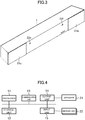
- FIG. 2 is a block diagram schematically showing the hardware configuration of the front unit 1.
- FIG. 3 is a perspective view showing the appearance of the front unit 1.
- the front unit 1 includes a processor 11, a storage unit 12, a communication unit 13, an output unit 14, an input unit 15, speakers 21, and a microphone 22.
- the input unit 15 is connected to the microphone 22 and to a sound source 23 such as the television 4 and other audio apparatuses.
- the speakers 21 includes a left speaker 21a and a right speaker 21b spaced apart from each other.
- the microphone 22 includes microphones 22e, 22f.
- the front unit 1 has a horizontally long shape and is generally arranged parallel to a side of the screen of the television 4, the side extends laterally.
- the front unit 1 has the left speaker 21a and the right speaker 21b arranged, laterally spaced apart from each other.
- the microphones 22e, 22f are spaced apart from each other and laid laterally side by side.
- multiple array speakers laid laterally side by side may be arranged instead of the left speaker 21a and the right speaker 21b.
- the front unit 1 may also be implemented by a plurality of apparatuses connected to each other.
- the front unit 1 may be made up of an AV amplifier, and an R-channel speaker and an L-channel speaker which are connected to the AV amplifier.
- the processor 11 operates according to a program stored in the storage unit 12 and thus controls the communication unit 13, the output unit 14, and the input unit 15.
- the program may be stored in a computer-readable storage medium such as a flash memory, or may be provided via a network.
- the storage unit 12 is made up of a memory device such as a DRAM and flash memory.
- the storage unit 12 stores the program.
- the storage unit 12 also stores information and results of computations inputted from the processor 11 and the communication unit 13 or the like.
- the communication unit 13 is made up of an integrated circuit that forms a wired LAN, wireless LAN or Bluetooth (trademark) transceiver, and a connector, an antenna and the like.
- the communication unit 13 communicates with another device via a network.
- the output unit 14 includes, for example, a DA converter and a headphone terminal and is connected to the speaker 21 or the like.
- the input unit 15 includes, for example, an AD converter, a line input terminal, a digital audio input interface, and an HDMI (trademark) input interface.
- FIG. 4 is a block diagram schematically showing the hardware configuration of the speaker unit 2.
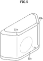
- FIG. 5 shows the appearance of the speaker unit 2.
- FIG. 4 shows an example of the speaker unit 2 generally called a wireless speaker.
- the speaker unit 2 includes a processor 11, a storage unit 12, a communication unit 13, an output unit 14, an input unit 15, a speaker 21, and a microphone 22. Details of the processor 11, the storage unit 12, and the communication unit 13 are similar to those included in the front unit 1 and therefore will not be described further.
- the output unit 14 includes, for example, a DA converter and is connected to the speaker 21.
- the input unit 15 includes an AD converter and is connected to the microphone 22.
- the microphone 22 includes a microphone 22a on the left-hand side, a microphone 22b on the right-hand side, and a microphone 22c on at the bottom.
- the speaker unit 2 receives audio data wirelessly from an apparatus such as the front unit 1 and outputs a sound represented by the audio data from the built-in speaker 21.
- the speaker unit 2 receives the audio data via the communication unit 13.
- the speaker unit 2 may be connected to the front unit 1 and an amplifier via a cable.
- FIG. 6 is a block diagram showing the functional configuration of the surround system.
- the surround system includes a speaker position detection unit 51, an audio parameter setting unit 52, an audio signal output unit 53, and a detection response unit 71.
- the speaker position detection unit 51 functionally includes a test sound output instruction unit 56, a test sound detection result acquisition unit 57, and a position calculation unit 58.
- the speaker position detection unit 51, the audio parameter setting unit 52, and the audio signal output unit 53 are implemented by the processor 11 included in the front unit 1 executing a program stored in the storage unit 12 and thus controlling the communication unit 13, the output unit 14, the input unit 15 and the like.
- the detection response unit 71 is implemented by the processor 11 included in the speaker unit 2 executing a program stored in the storage unit 12 and thus controlling the communication unit 13, the input unit 15 and the like.
- the speaker position detection unit 51, the audio parameter setting unit 52 and the like may be implemented by another apparatus having the processor 11, the storage unit 12, and the communication unit 13, such as a smartphone.
- the speaker position detection unit 51 calculates relative position information between the front unit 1 and the speaker unit 2.
- the test sound output instruction unit 56 included in the speaker position detection unit 51 causes the speaker 21 included in one of the front unit 1 and the speaker unit 2 to output a test sound.
- the test sound detection result acquisition unit 57 included in the speaker position detection unit 51 acquires information of a test sound detected by the other of the front unit 1 and the speaker unit 2.
- the position calculation unit 58 included in the speaker position detection unit 51 calculates relative position information between the front unit 1 and the speaker unit 2, based on the acquired information of the test sound.
- the position information may express the relative position between the front unit 1 and the speaker unit 2 in the form of coordinates or in the form of direction and distance, or may express only the direction of the speaker unit 2 with respect to the front unit 1 as a reference point.
- the audio parameter setting unit 52 decides a parameter of an audio signal outputted to the speaker unit 2, based on the calculated position information. More specifically, the audio parameter setting unit 52 decides the channel of an audio signal allocated to the speaker unit 2, based on the position and direction of the speaker unit 2 expressed by the position information. The audio parameter setting unit 52 may also decide a parameter related to correction of an audio signal, such as correction of the amount of delay in the output of a sound and frequency characteristics thereof.
- the audio signal output unit 53 outputs an audio signal to the speaker 21 included in the front unit 1 and to the speaker unit 2, based on the parameter thus decided and an audio signal supplied from the sound source 23.
- the audio signal may be an electrical signal or data. Based on the audio signal thus outputted, a sound is outputted from the speaker 21 included in the front unit 1 and in the speaker unit 2.
- FIG. 7 is a flowchart showing an example of the processing by the front unit 1 according to the first embodiment.
- FIG. 8 explains an example of the relation between the speaker unit 2 and the front unit 1.
- FIG. 9 is a flowchart showing an example of the processing by the speaker unit 2.
- FIGS. 7 to 9 show an example in the case where a test sound is outputted from the left speaker 21a and the right speaker 21b of the front unit 1 and where a test sound detected by a plurality of microphones 22a, 22b included in each of the speaker units 2 is used.
- a part or the entirety of the processing shown in FIG. 7 may be executed by another apparatus such as a smartphone.
- the processing of steps S102, S104, S105, S107, and S108 is carried out for each speaker unit 2.
- the speaker position detection unit 51 recognizes the speaker unit 2 connected via the communication unit 13 (step S101).
- the speaker position detection unit 51 may recognize the speaker unit 2 connected via a cable. It is assumed that the time of the front unit 1 and the time of the speaker unit 2 are synchronized by a known technique.
- test sound output instruction unit 56 transmits to the speaker unit 2 a notification to start outputting a test sound (step S102). Meanwhile, the detection response unit 71 of each speaker unit 2 receives the notification to start outputting a test sound, transmitted from the front unit 1 (step S201) . The detection response unit 71 causes each microphone 22 arranged in the speaker unit 2 to operate (step S202).
- the test sound output instruction unit 56 causes a test sound to be outputted from the left speaker 21a of the front unit 1 (step S103).
- the test sound may be a pulse-like sound, a sound that changes in volume in a sweep-like manner, or a section with changing volume or frequency of music that has been played for some time.
- the detection response unit 71 of the speaker unit 2 detects the test sound inputted to a plurality of microphones 22 and transmits information about the test sound. More specifically, the detection response unit 71 acquires times t1R, t1L when the microphones 22a, 22b detect the test sound (step S203) . The detection response unit 71 then transmits the acquired times t1R, t1L (step S204). The processing of steps S203 and S204 is carried out every time the microphones 22 receive a test sound. The detection response unit 71 may transmit data of the test sound inputted to the microphones 22a, 22b or the difference between the times t1R and t1L, instead of the times t1R, t1L.
- the test sound detection result acquisition unit 57 of the speaker position detection unit 51 receives the information about the test sound from the detection response unit 71 and thus acquires the time difference ⁇ Tl between the times t1L, t1R when the microphones 22a, 22b included in the speaker unit 2 receive the test sound (step S104). To acquire the time difference ⁇ Tl, the test sound detection result acquisition unit 57 may calculate the difference between the times t1L and t1R or may receive the difference between the times t1R and t1L from the speaker unit 2. The test sound detection result acquisition unit 57 may also receive data of the test sound inputted to the microphones 22a, 22b and analyze the data, thus finding the times t1R, t1L.
- FIG. 10 explains the time t0 of outputting a test sound from the speaker 21 and the times t1R, t1L of detecting the test sound by the microphones 22.
- FIG. 10 shows an example in the case where the speaker 21 of the front unit 1 outputs a test sound at the time t0, the microphone 22a detects the test sound at the time t1L, and the microphone 22b detects the test sound at the time t1R.
- the taken time ⁇ t1L for the test sound to reach the microphone 22a from the speaker 21 is found by an equation of (t1L-t0) .
- the taken time ⁇ t1R for the test sound to reach the microphone 22b from the speaker 21 is found by an equation of (t1R-t0) .
- the distances between the speaker 21 outputting the test sound and the microphones 22a, 22b detecting the test sound are found by multiplying the times taken ⁇ t1L, ⁇ t1R by the speed of sound.
- the test sound detection result acquisition unit 57 normalizes the time difference ⁇ Tl, based on the times taken for the test sound to reach the microphones 22 from the speaker 21 (step S105). More specifically, the test sound detection result acquisition unit 57 divides the time difference ⁇ Tl acquired in step S104, for example, by the average of the times taken ⁇ t1R, ⁇ t1L, and thus calculates the normalized time difference ⁇ Tl. The normalization corrects variations in the time difference due to the distance between the speaker unit 2 and the front unit 1.
- the speaker position detection unit 51 carries out the processing of steps S106 to S108 to find a time difference ⁇ Tr for the right speaker 21b of the front unit 1.
- the processing of steps S106 to S108 is different from the processing of steps S103 to S105 in that the speaker 21 outputting a test sound is the right speaker 21b of the front unit 1.
- the test sound output instruction unit 56 causes a test sound to be outputted from the right speaker 21b of the front unit 1 (step S106).
- the test sound detection result acquisition unit 57 receives the information about the test sound from the detection response unit 71 and thus acquires the time difference ⁇ Tr between the times t1L, t1R when the microphones 22a, 22b included in the speaker unit 2 receive the test sound (step S107) .
- the test sound detection result acquisition unit 57 also normalizes the time difference ⁇ Tr, based on the times taken ⁇ t1L, ⁇ t1R for the test sound to reach the microphones 22 from the speaker 21 (step S108) .
- the position calculation unit 58 of the speaker position detection unit 51 specifies the position of the speaker unit 2, based on the normalized time differences ⁇ Tl, ⁇ Tr (step S109) .
- the speaker unit 2 arranged behind the listener or the like often faces in a direction (upward in FIG. 8 ) opposite to the direction in which the front unit 1 faces, due to its relation with the wall of the room.
- the distances between the left speaker 21a and the microphones 22a, 22b of the speaker unit 2a are defined as D1, D2, respectively, and the distances between the left speaker 21a and the microphones 22a, 22b of the speaker unit 2b are defined as D3, D4, respectively.
- D1-D2)>(D3-D4) holds.
- (D1-D2) and (D3-D4) become greater as the speaker unit 2 is situated more to the left.
- the normalized time difference ⁇ Tl or ⁇ Tr On the assumption that the speed of sound is constant, the same characteristic applies to the normalized time difference ⁇ Tl or ⁇ Tr.
- the position calculation unit 58 specifies the position of the speaker unit 2, using the foregoing characteristic. If the time differences ⁇ Tl, ⁇ Tr are (t1L-t1R), the position calculation unit 58 sorts out the speaker units 2, based on the time difference ⁇ Tl found for each of the speaker units 2, and acquires a first list that places the speaker units 2 in an order. The position calculation unit 58 also sorts out the speaker units 2, based on the time difference ⁇ Tr found for each of the speaker units 2, and acquires a second list that places the speaker units 2 in an order. If the first list and the second list place the speaker units 2 in the same order, it is determined that the speaker unit 2 with a greater time difference ⁇ Tl is situated more to the left.
- the position calculation unit 58 determines that the speaker unit 2 with a greater time difference ⁇ Tl is situated to the left while the speaker unit 2 with a smaller time difference ⁇ Tl is situated to the right. Meanwhile, if the first list and the second list place the speaker units 2 in different orders, the position calculation unit 58 averages the values ⁇ Tl and ⁇ Tr for each speaker unit 2 and determines that the speaker unit 2 with which this average is greater is situated more to the left. The position calculation unit 58 may also calculate how far each speaker unit 2 is away from the center, based on the time differences ⁇ Tr, ⁇ Tl or the average of these. The position calculation unit 58 may specify whether the position of the speaker unit 2 is to the left or to the right, simply based on whether the time differences ⁇ Tr, ⁇ Tl or the average of these is positive or negative.
- steps S101 to S109 may be carried out with respect to the microphone 22c and the microphone 22a or 22b, instead of the microphones 22a, 22b, to detect the position in the direction of height of the speaker unit 2.
- the speaker position detection unit 51 may specify the position in a vertical direction, simply based on the time difference found for one speaker 21 of the front unit 1.
- step S110 the audio parameter setting unit 52 allocates an audio channel to each of the speaker units 2, based on the specified positions of the speaker units 2.
- the audio signal output unit 53 outputs an audio signal corresponding to the allocated audio channel or the like, to each speaker unit 2.
- the audio parameter setting unit 52 may decide a parameter such as the amount of delay in and frequency characteristics of the audio signal outputted to each speaker unit 2, as well as the channel.
- the above processing reduces the time and effort for the user to set a parameter such as the channel of an audio signal outputted from the speaker units 2.
- a parameter such as the channel of an audio signal outputted from the speaker units 2.
- the user neither has to install a microphone at a listening position nor has to manually associate the speaker units 2 with channels.
- FIG. 11 explains another example of the relation between the speaker unit 2 and the front unit 1.
- FIG. 12 is a flowchart showing another example of the processing by the speaker position detection unit 51.
- the microphone 22 included in the front unit 1 detects a test sound outputted from the speaker 21 included in each of the speaker units 2a, 2b, thus detecting the position of the speaker unit 2.
- FIG. 12 shows processing carried out instead of the processing of steps S101 to S109 of FIG. 7 .
- FIGS. 11 and 12 is different from the example of FIGS. 7 and 8 in the following features.
- the speaker 21 of the speaker unit 2 outputs a test sound
- a plurality of microphones 22 of the front unit 1 receives the test sound.
- the timing of detecting a test sound tends not to vary due to the direction of the speaker unit 2. Therefore, the speaker position detection unit 51 calculates position information of the speaker unit 2, based on one speaker 21.
- the speaker position detection unit 51 of the front unit 1 carries out the following processing.
- the speaker position detection unit 51 recognizes the speaker unit 2 available for communication (step S151).
- the test sound output instruction unit 56 transmits a signal to instruct the speaker unit 2 to output a test sound and thus causes the speaker 21 included in the speaker unit 2 to output a test sound (step S152) .
- the test sound detection result acquisition unit 57 acquires the times taken ⁇ t1L, ⁇ t1R from the output of the test sound to the detection of the test sound by the microphones 22e, 22f of the front unit 1 (step S153).
- the position calculation unit 58 then calculates position information representing the position of the speaker unit 2, based on the times taken ⁇ t1L, ⁇ t1R.
- the distance Dm between the microphone 22e and the microphone 22f is known in advance. Therefore, based on the distances D5, D6 found by multiplying the times taken ⁇ t1L, ⁇ t1R by the speed of sound, a triangle having the speaker 21 of the speaker unit 2 and the microphones 22e, 22f of the front unit 1 at the vertices is univocally defined.
- the position calculation unit 58 finds an angle ⁇ 1 of the speaker unit 2a to the microphone 22e as a reference point and an angle ⁇ 2 of the speaker unit 2a to the microphone 22f as a reference point, based on the law of cosines and the distances Dm, D5, D6.
- the position calculation unit 58 may calculate a trigonometric function using the angle ⁇ 1 and the distance D5, or the angle ⁇ 2 and the distance D6, to find the coordinates of the speaker unit 2a. This computation is also carried out with respect to the information acquired for the other speaker unit 2.
- the test sound detection result acquisition unit 57 may acquire the difference ⁇ T between the time t2L when the microphone 22e receives the test sound and the time t2R when the microphone 22f receives the test sound.
- the position calculation unit 58 calculates the direction with respect to the direction in which the microphones 22 of the front unit 1 are arrayed, based on the sign and magnitude of the difference ⁇ T.
- a microphone array includes multiple microphones 22.
- the direction from which a test sound comes is calculated by a known computation technique.
- the speaker position detection unit 51 carries out this computation and thus calculates the direction of the test sound.
- relative position information between the front unit 1 and the speaker unit 2 is calculated using a plurality of speakers 21 arranged in the front unit 1 and one microphone 22 arranged in the speaker unit 2.
- the speaker unit 2 may have only one microphone. The other parts of the hardware configuration and functional configuration of the surround system according to the second embodiment will not be described further in detail.
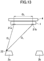
- FIG. 13 explains an example of the relation between the speaker unit 2 and the front unit 1 according to the second embodiment.
- at least one microphone 22 included in the speaker unit 2 detects a test sound outputted from each of the speakers 21 included in the front unit 1. The position of the speaker unit 2 is thus detected.
- the output side and input side of the test sound are the reverse of those in the configuration shown in FIG. 11 .
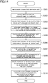
- FIG. 14 is a flowchart showing an example of the processing by the front unit 1 according to the second embodiment.
- FIG. 14 corresponds to FIG. 7 of the first embodiment.
- a part or the entirety of the processing shown in FIG. 14 may be executed by another apparatus such as a smartphone.
- the processing of steps S302 to S309 is carried out for each speaker unit 2. It is assumed that the times of the front unit 1 and the speaker unit 2 are synchronized by a known technique.
- the speaker position detection unit 51 recognizes the speaker unit 2 connected via the communication unit 13 (step S301).
- the speaker position detection unit 51 may recognize the speaker unit 2 connected via a cable.
- test sound output instruction unit 56 instructs the speaker unit 2 to cause the microphone 22 of the speaker unit 2 to operate (step S302) . More specifically, the test sound output instruction unit 56 transmits, to each speaker unit 2, a notification to start outputting a test sound.
- the operation of each speaker unit 2 is similar to that in the first embodiment except for targeting a test sound to one microphone 22 and therefore will not be described further in detail.
- the test sound output instruction unit 56 causes a test sound to be outputted from the left speaker 21a of the front unit 1 (step S303) . Then, the speaker unit 2 detects the test sound inputted to the microphone 22 and transmits information about the test sound.
- the information about the test sound is, for example, the time t2L when the test sound is received, or audio data of the microphone 22.
- the test sound detection result acquisition unit 57 of the speaker position detection unit 51 receives the information about the test sound and thus acquires the taken time ⁇ t2L from the output of the test sound to the reception of the test sound by the microphone 22 (step S304). More specifically, the test sound detection result acquisition unit 57 may subtract the time t0L when the left speaker 21a of the front unit 1 outputs the test sound from the time t2L when the test sound is received, thus calculating the taken time ⁇ t2L.
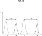
- FIG. 15 explains the times t0L, t0R of outputting a test sound from the speakers 21 and the times t2L, t2R of detecting the test sound by the microphone 22.
- the left speaker 21a of the front unit 1 outputs a test sound at the time t0L and the microphone 22 of the speaker unit 2 detects the test sound at the time t2L.
- the right speaker 21b outputs a test sound at the time t0R and the microphone 22 of the speaker unit 2 detects the test sound at the time t2R.
- the taken time ⁇ t2R may be (t2R-t0R).
- the test sound detection result acquisition unit 57 calculates the distance Da between the left speaker 21a and the speakers 21, based on the taken time ⁇ t2L (step S305).
- the test sound detection result acquisition unit 57 multiplies the times taken ⁇ t2L by the speed of sound and thus calculates the distance Da.
- the speaker position detection unit 51 carries out the processing of steps S306 to S308 to find the distance Db for the right speaker 21b of the front unit 1.
- the processing of steps S306 to S308 is different from the processing of steps S303 to S305 in that the speaker 21 outputting a test sound is the right speaker 21b of the front unit 1.
- the test sound output instruction unit 56 causes a test sound to be outputted from the right speaker 21b of the front unit 1 (step S306).
- the test sound detection result acquisition unit 57 receives the information about the test sound from the detection response unit 71 and thus acquires the taken time ⁇ t2R from the output of the test sound to the time t2R when the microphone 22 receives the test sound (step S307).
- the test sound detection result acquisition unit 57 calculates the distance Db between the right speaker 21b and the speaker unit 2, based on the taken time ⁇ t2R (step S308).
- the position calculation unit 58 of the speaker position detection unit 51 specifies the position of the speaker unit 2, based on the distances Da, Db thus calculated and the distance Do between the right speaker 21b and the left speaker 21a (step S309).
- a triangle having the two speakers 21 of the front unit 1 and the one speaker unit 2a at the vertices is univocally defined.
- the position calculation unit 58 finds angles ⁇ 3, ⁇ 4 of the speaker unit 2a to the left speaker 21a and the right speaker 21b as reference points, based on the law of cosines and the distances Da, Db, Do. The direction of the speaker unit 2a with respect to the front unit 1 as a reference point is thus found.
- the position calculation unit 58 may calculate a trigonometric function using the angle ⁇ 3 and the distance Da, or the angle ⁇ 4 and the distance Db, to find the coordinates of the speaker unit 2a. This computation is also carried out with respect to the information acquired for the other speaker unit 2.
- a speaker position detection system includes: a first speaker unit having at least one speaker; a second speaker unit having a speaker and a plurality of microphones; and a detection unit which calculates relative position information between the first speaker unit and the second speaker unit.
- the detection unit causes the speaker included in the first speaker unit to output a test sound, and calculates the position information representing a position of one of the first speaker unit and the second speaker unit, based on the test sound detected by each of the plurality of microphones.
- the detection unit may calculate the position information representing the position of one of the first speaker unit and the second speaker unit, based on a difference between times when the respective microphones of the plurality of microphones detect the outputted sound.
- the detection unit may cause the speaker included in the first speaker unit to output a test sound, and may calculate the relative position information between the first speaker unit and the second speaker unit, based on the test sound detected by each of the plurality of microphones.
- a speaker position detection method includes: causing a speaker included in a first speaker unit having at least one speaker to output a test sound; and calculating position information representing a position of one of the first speaker unit and a second speaker unit, based on the test sound detected by each of a plurality of microphones included in the second speaker unit having a speaker.
- a speaker position detection device includes: a unit which causes a speaker included in a first speaker unit having at least one speaker to output a test sound; and a unit which calculates position information representing a position of one of the first speaker unit and a second speaker unit, based on the test sound detected by each of a plurality of microphones included in the second speaker unit having a speaker.
- a program according to the invention causes a computer to function as: a unit which causes a speaker included in a first speaker unit having at least one speaker to output a test sound; and a unit which calculates position information representing a position of one of the first speaker unit and a second speaker unit, based on the test sound detected by each of a plurality of microphones included in the second speaker unit having a speaker.
- An information storage medium according to the invention is a computer-readable information storage medium in which the program is recorded.
- Another speaker position detection system includes: a first speaker unit having a plurality of speakers; a second speaker unit having a speaker and a microphone; and a detection unit which calculates position information representing a position of one of the first speaker unit and the second speaker unit.
- the detection unit causes at least two of the plurality of speakers included in the first speaker unit to output a test sound, and calculates the position information representing a position of one of the first speaker unit and the second speaker unit, based on the test sound outputted from each of the at least two speakers and detected by each of the microphones.
- the detection unit may cause at least two of the plurality of speakers included in the first speaker unit to output a test sound, and may calculate relative position information between the first speaker unit and the second speaker unit, based on the test sound outputted from each of the at least two speakers and detected by each of the microphones.
- Another speaker position detection method includes: causing at least two of a plurality of speakers included in a first speaker unit to output a test sound; and calculating position information representing a position of one of the first speaker unit and a second speaker unit, based on the test sound detected from each of the at least two speakers by a microphone included in the second speaker unit.
- Another speaker position detection device includes: a unit which causes at least two of a plurality of speakers included in a first speaker unit to output a test sound; and a unit which calculates position information representing a position of one of the first speaker unit and a second speaker unit, based on the test sound detected from each of the at least two speakers by a microphone included in the second speaker unit.
- Another program according to the invention causes a computer to function as: a unit which causes at least two of a plurality of speakers included in a first speaker unit to output a test sound; and a unit which calculates position information representing a position of one of the first speaker unit and a second speaker unit, based on the test sound detected from each of the at least two speakers by a microphone included in the second speaker unit.
- Another information storage medium according to the invention is a computer-readable information storage medium in which the program is recorded.
- the speaker position detection system may further include a parameter decision unit which decides a parameter of an audio signal outputted to at least one of the first speaker unit and the second speaker unit, based on the calculated position information.
- the parameter decision unit may decide a channel of an audio signal allocated to at least one of the first speaker unit and the second speaker unit, based on the calculated position information.
Landscapes
- Engineering & Computer Science (AREA)
- Physics & Mathematics (AREA)
- Acoustics & Sound (AREA)
- Signal Processing (AREA)
- Health & Medical Sciences (AREA)
- Theoretical Computer Science (AREA)
- General Health & Medical Sciences (AREA)
- Human Computer Interaction (AREA)
- General Engineering & Computer Science (AREA)
- General Physics & Mathematics (AREA)
- Audiology, Speech & Language Pathology (AREA)
- Otolaryngology (AREA)
- Stereophonic System (AREA)
- Circuit For Audible Band Transducer (AREA)
Applications Claiming Priority (1)
| Application Number | Priority Date | Filing Date | Title |
|---|---|---|---|
| JP2017079730A JP6904031B2 (ja) | 2017-04-13 | 2017-04-13 | スピーカ位置検出システム、スピーカ位置検出装置、及びスピーカ位置検出方法 |
Publications (2)
| Publication Number | Publication Date |
|---|---|
| EP3389286A1 true EP3389286A1 (fr) | 2018-10-17 |
| EP3389286B1 EP3389286B1 (fr) | 2021-06-02 |
Family
ID=61972349
Family Applications (1)
| Application Number | Title | Priority Date | Filing Date |
|---|---|---|---|
| EP18166996.1A Active EP3389286B1 (fr) | 2017-04-13 | 2018-04-12 | Système de détection de position de haut-parleur, dispositif de détection de position de haut-parleur et procédé de détection de position de haut-parleur |
Country Status (4)
| Country | Link |
|---|---|
| US (1) | US10959016B2 (fr) |
| EP (1) | EP3389286B1 (fr) |
| JP (1) | JP6904031B2 (fr) |
| CN (1) | CN108737948B (fr) |
Families Citing this family (13)
| Publication number | Priority date | Publication date | Assignee | Title |
|---|---|---|---|---|
| US10901684B2 (en) * | 2016-12-13 | 2021-01-26 | EVA Automation, Inc. | Wireless inter-room coordination of audio playback |
| TWI757600B (zh) * | 2019-05-07 | 2022-03-11 | 宏碁股份有限公司 | 揚聲器調整方法與使用此方法的電子裝置 |
| TWI715027B (zh) * | 2019-05-07 | 2021-01-01 | 宏碁股份有限公司 | 揚聲器調整方法與使用此方法的電子裝置 |
| CN111970606B (zh) * | 2019-05-20 | 2022-05-31 | 宏碁股份有限公司 | 扬声器调整方法与使用此方法的电子装置 |
| US11044559B2 (en) * | 2019-10-08 | 2021-06-22 | Dish Network L.L.C. | Systems and methods for facilitating configuration of an audio system |
| KR102304815B1 (ko) | 2020-01-06 | 2021-09-23 | 엘지전자 주식회사 | 오디오 장치 및 그의 동작방법 |
| EP3900815A1 (fr) | 2020-04-23 | 2021-10-27 | Bellco S.r.l. con Unico Socio | Sac de dissolution et buse |
| EP4201082B1 (fr) * | 2020-08-24 | 2025-10-08 | Sonos, Inc. | Dispositifs pour réproduire du son multi-canal et système et procédé correspondants |
| CN112190259B (zh) * | 2020-09-10 | 2024-06-28 | 北京济声科技有限公司 | 用于测试声源定位能力的方法、测试者终端、受试者终端 |
| EP3991768A1 (fr) | 2020-10-28 | 2022-05-04 | Bellco S.r.l. con Unico Socio | Système venturi coaxial |
| JP2022123395A (ja) * | 2021-02-12 | 2022-08-24 | パイオニア株式会社 | 音源方向検出システム、スピーカセット及び音源方向検出装置 |
| TWI841874B (zh) * | 2021-10-27 | 2024-05-11 | 瑞昱半導體股份有限公司 | 音訊控制裝置與多聲道音響系統之控制方法 |
| CN116074689A (zh) * | 2021-11-04 | 2023-05-05 | 瑞昱半导体股份有限公司 | 音频控制装置与多声道音响系统的控制方法 |
Citations (2)
| Publication number | Priority date | Publication date | Assignee | Title |
|---|---|---|---|---|
| EP1718114A1 (fr) * | 2004-02-18 | 2006-11-02 | Yamaha Corporation | Dispositif de reproduction acoustique et methode d'identification de position de haut-parleur |
| WO2008126161A1 (fr) | 2007-03-06 | 2008-10-23 | Pioneer Corporation | Dispositif et procédé d'attribution de canal pour un système de reproduction multicanaux |
Family Cites Families (18)
| Publication number | Priority date | Publication date | Assignee | Title |
|---|---|---|---|---|
| US5912980A (en) | 1995-07-13 | 1999-06-15 | Hunke; H. Martin | Target acquisition and tracking |
| US6741273B1 (en) | 1999-08-04 | 2004-05-25 | Mitsubishi Electric Research Laboratories Inc | Video camera controlled surround sound |
| JP3521900B2 (ja) * | 2002-02-04 | 2004-04-26 | ヤマハ株式会社 | バーチャルスピーカアンプ |
| JP4765289B2 (ja) * | 2003-12-10 | 2011-09-07 | ソニー株式会社 | 音響システムにおけるスピーカ装置の配置関係検出方法、音響システム、サーバ装置およびスピーカ装置 |
| JP2006352570A (ja) * | 2005-06-16 | 2006-12-28 | Yamaha Corp | スピーカシステム |
| US8320824B2 (en) * | 2007-09-24 | 2012-11-27 | Aliphcom, Inc. | Methods and systems to provide automatic configuration of wireless speakers |
| CN101964937A (zh) * | 2009-07-23 | 2011-02-02 | 先歌国际影音股份有限公司 | 多方向发声系统 |
| US9015612B2 (en) | 2010-11-09 | 2015-04-21 | Sony Corporation | Virtual room form maker |
| US9084036B2 (en) * | 2011-05-17 | 2015-07-14 | Alcatel Lucent | Signal source localization using compressive measurements |
| US9408011B2 (en) * | 2011-12-19 | 2016-08-02 | Qualcomm Incorporated | Automated user/sensor location recognition to customize audio performance in a distributed multi-sensor environment |
| AU2013223971B2 (en) | 2012-02-24 | 2016-03-31 | Fraunhofer-Gesellschaft Zur Foerderung Der Angewandten Forschung E.V. | Apparatus for providing an audio signal for reproduction by a sound transducer, system, method and computer program |
| KR20140099122A (ko) * | 2013-02-01 | 2014-08-11 | 삼성전자주식회사 | 전자 장치, 위치 검출 장치, 스피커 자동 설정 시스템 및 방법 |
| JP6357884B2 (ja) | 2014-06-02 | 2018-07-18 | ヤマハ株式会社 | 位置特定装置およびオーディオ装置 |
| CN112929788B (zh) | 2014-09-30 | 2025-01-07 | 苹果公司 | 确定扬声器位置变化的方法 |
| EP3024253A1 (fr) * | 2014-11-21 | 2016-05-25 | Harman Becker Automotive Systems GmbH | Système et procédé audio |
| JP2016119635A (ja) * | 2014-12-23 | 2016-06-30 | ヤマハ株式会社 | 時間差算出装置及び端末装置 |
| DE102015106114B4 (de) * | 2015-04-21 | 2017-10-26 | D & B Audiotechnik Gmbh | Verfahren und einrichtung zur positionserkennung von lautsprecherboxen einer lautsprecherboxenanordnung |
| JP6604865B2 (ja) * | 2016-02-08 | 2019-11-13 | 株式会社ディーアンドエムホールディングス | ワイヤレスオーディオシステム、コントローラ、ワイヤレススピーカ、およびコンピュータで読み取り可能なプログラム |
-
2017
- 2017-04-13 JP JP2017079730A patent/JP6904031B2/ja active Active
-
2018
- 2018-04-12 US US15/951,433 patent/US10959016B2/en active Active
- 2018-04-12 EP EP18166996.1A patent/EP3389286B1/fr active Active
- 2018-04-13 CN CN201810331054.4A patent/CN108737948B/zh active Active
Patent Citations (2)
| Publication number | Priority date | Publication date | Assignee | Title |
|---|---|---|---|---|
| EP1718114A1 (fr) * | 2004-02-18 | 2006-11-02 | Yamaha Corporation | Dispositif de reproduction acoustique et methode d'identification de position de haut-parleur |
| WO2008126161A1 (fr) | 2007-03-06 | 2008-10-23 | Pioneer Corporation | Dispositif et procédé d'attribution de canal pour un système de reproduction multicanaux |
Non-Patent Citations (1)
| Title |
|---|
| ATKINSON BOB ET AL: "An Internet Protocol (IP) Sound System", AES CONVENTION 117; OCTOBER 2004, AES, 60 EAST 42ND STREET, ROOM 2520 NEW YORK 10165-2520, USA, 1 October 2004 (2004-10-01), XP040506960 * |
Also Published As
| Publication number | Publication date |
|---|---|
| JP2018182534A (ja) | 2018-11-15 |
| JP6904031B2 (ja) | 2021-07-14 |
| CN108737948B (zh) | 2021-06-04 |
| US20180302711A1 (en) | 2018-10-18 |
| CN108737948A (zh) | 2018-11-02 |
| EP3389286B1 (fr) | 2021-06-02 |
| US10959016B2 (en) | 2021-03-23 |
Similar Documents
| Publication | Publication Date | Title |
|---|---|---|
| EP3389286A1 (fr) | Système de détection de position de haut-parleur, dispositif de détection de position de haut-parleur et procédé de détection de position de haut-parleur | |
| US11990880B2 (en) | Audio system equalizing | |
| KR102533698B1 (ko) | 음향 출력 시스템을 구성하는 전자 장치, 음향 출력 장치 및 그 제어 방법 | |
| US20190387344A1 (en) | Surround audio device and method of providing multi-channel surround audio signal to a plurality of electronic devices including a speaker | |
| US9900723B1 (en) | Multi-channel loudspeaker matching using variable directivity | |
| US10321255B2 (en) | Speaker location identifying system, speaker location identifying device, and speaker location identifying method | |
| US20140219483A1 (en) | System and method for setting audio output channels of speakers | |
| US10026416B2 (en) | Audio system, audio device, mobile terminal device and audio signal control method | |
| EP1919259A2 (fr) | Système, appareil, procédé et programme permettant de commander une sortie | |
| US9961480B2 (en) | Automatic speaker setup | |
| EP2816823B1 (fr) | Système audio, appareil audio et son procédé de mise en correspondance de canaux | |
| EP2823650A1 (fr) | Système de rendu audio | |
| US20170325028A1 (en) | Method and device for outputting audio signal on basis of location information of speaker | |
| US20070133810A1 (en) | Sound field correction apparatus | |
| EP3827597B1 (fr) | Haut-parleur bluetooth conçu pour produire du son ainsi que pour servir simultanément de récepteur et de source | |
| JP2003250200A (ja) | マルチチャンネルオーディオシステム | |
| EP1933596A1 (fr) | Dispositif de correction de signal audio multicanal | |
| US11006217B2 (en) | Audio signal distribution device, audio signal reception device, audio signal processing system, and audio signal processing method | |
| KR101782980B1 (ko) | 모바일 기기와 채널 스피커간 무선 송수신 시스템 및 그 방법 | |
| EP3537728B1 (fr) | Système de détermination d'état de connexion pour haut-parleurs, dispositif acoustique et procédé de détermination d'état de connexion pour haut-parleurs | |
| KR20070051140A (ko) | 멀티 채널 시스템의 스피커 출력 장치 및 방법 | |
| HK40042200A (en) | Bluetooth speaker configured to produce sound as well as simultaneously act as both sink and source | |
| HK1235195A1 (en) | System and method for enhancing virtual audio height perception | |
| KR20150079514A (ko) | 오디오 장치 및 이의 오디오 신호 전송 방법, 그리고 오디오 시스템 |
Legal Events
| Date | Code | Title | Description |
|---|---|---|---|
| PUAI | Public reference made under article 153(3) epc to a published international application that has entered the european phase |
Free format text: ORIGINAL CODE: 0009012 |
|
| STAA | Information on the status of an ep patent application or granted ep patent |
Free format text: STATUS: THE APPLICATION HAS BEEN PUBLISHED |
|
| AK | Designated contracting states |
Kind code of ref document: A1 Designated state(s): AL AT BE BG CH CY CZ DE DK EE ES FI FR GB GR HR HU IE IS IT LI LT LU LV MC MK MT NL NO PL PT RO RS SE SI SK SM TR |
|
| AX | Request for extension of the european patent |
Extension state: BA ME |
|
| STAA | Information on the status of an ep patent application or granted ep patent |
Free format text: STATUS: REQUEST FOR EXAMINATION WAS MADE |
|
| 17P | Request for examination filed |
Effective date: 20190328 |
|
| RBV | Designated contracting states (corrected) |
Designated state(s): AL AT BE BG CH CY CZ DE DK EE ES FI FR GB GR HR HU IE IS IT LI LT LU LV MC MK MT NL NO PL PT RO RS SE SI SK SM TR |
|
| STAA | Information on the status of an ep patent application or granted ep patent |
Free format text: STATUS: EXAMINATION IS IN PROGRESS |
|
| 17Q | First examination report despatched |
Effective date: 20191202 |
|
| GRAP | Despatch of communication of intention to grant a patent |
Free format text: ORIGINAL CODE: EPIDOSNIGR1 |
|
| STAA | Information on the status of an ep patent application or granted ep patent |
Free format text: STATUS: GRANT OF PATENT IS INTENDED |
|
| INTG | Intention to grant announced |
Effective date: 20210104 |
|
| INTG | Intention to grant announced |
Effective date: 20210113 |
|
| GRAS | Grant fee paid |
Free format text: ORIGINAL CODE: EPIDOSNIGR3 |
|
| GRAA | (expected) grant |
Free format text: ORIGINAL CODE: 0009210 |
|
| STAA | Information on the status of an ep patent application or granted ep patent |
Free format text: STATUS: THE PATENT HAS BEEN GRANTED |
|
| REG | Reference to a national code |
Ref country code: CH Ref legal event code: EP |
|
| AK | Designated contracting states |
Kind code of ref document: B1 Designated state(s): AL AT BE BG CH CY CZ DE DK EE ES FI FR GB GR HR HU IE IS IT LI LT LU LV MC MK MT NL NO PL PT RO RS SE SI SK SM TR |
|
| REG | Reference to a national code |
Ref country code: GB Ref legal event code: FG4D |
|
| REG | Reference to a national code |
Ref country code: AT Ref legal event code: REF Ref document number: 1399578 Country of ref document: AT Kind code of ref document: T Effective date: 20210615 |
|
| REG | Reference to a national code |
Ref country code: IE Ref legal event code: FG4D |
|
| REG | Reference to a national code |
Ref country code: DE Ref legal event code: R096 Ref document number: 602018017889 Country of ref document: DE |
|
| REG | Reference to a national code |
Ref country code: LT Ref legal event code: MG9D |
|
| PG25 | Lapsed in a contracting state [announced via postgrant information from national office to epo] |
Ref country code: BG Free format text: LAPSE BECAUSE OF FAILURE TO SUBMIT A TRANSLATION OF THE DESCRIPTION OR TO PAY THE FEE WITHIN THE PRESCRIBED TIME-LIMIT Effective date: 20210902 Ref country code: HR Free format text: LAPSE BECAUSE OF FAILURE TO SUBMIT A TRANSLATION OF THE DESCRIPTION OR TO PAY THE FEE WITHIN THE PRESCRIBED TIME-LIMIT Effective date: 20210602 Ref country code: LT Free format text: LAPSE BECAUSE OF FAILURE TO SUBMIT A TRANSLATION OF THE DESCRIPTION OR TO PAY THE FEE WITHIN THE PRESCRIBED TIME-LIMIT Effective date: 20210602 Ref country code: FI Free format text: LAPSE BECAUSE OF FAILURE TO SUBMIT A TRANSLATION OF THE DESCRIPTION OR TO PAY THE FEE WITHIN THE PRESCRIBED TIME-LIMIT Effective date: 20210602 |
|
| REG | Reference to a national code |
Ref country code: NL Ref legal event code: MP Effective date: 20210602 |
|
| REG | Reference to a national code |
Ref country code: AT Ref legal event code: MK05 Ref document number: 1399578 Country of ref document: AT Kind code of ref document: T Effective date: 20210602 |
|
| PG25 | Lapsed in a contracting state [announced via postgrant information from national office to epo] |
Ref country code: GR Free format text: LAPSE BECAUSE OF FAILURE TO SUBMIT A TRANSLATION OF THE DESCRIPTION OR TO PAY THE FEE WITHIN THE PRESCRIBED TIME-LIMIT Effective date: 20210903 Ref country code: RS Free format text: LAPSE BECAUSE OF FAILURE TO SUBMIT A TRANSLATION OF THE DESCRIPTION OR TO PAY THE FEE WITHIN THE PRESCRIBED TIME-LIMIT Effective date: 20210602 Ref country code: SE Free format text: LAPSE BECAUSE OF FAILURE TO SUBMIT A TRANSLATION OF THE DESCRIPTION OR TO PAY THE FEE WITHIN THE PRESCRIBED TIME-LIMIT Effective date: 20210602 Ref country code: LV Free format text: LAPSE BECAUSE OF FAILURE TO SUBMIT A TRANSLATION OF THE DESCRIPTION OR TO PAY THE FEE WITHIN THE PRESCRIBED TIME-LIMIT Effective date: 20210602 Ref country code: PL Free format text: LAPSE BECAUSE OF FAILURE TO SUBMIT A TRANSLATION OF THE DESCRIPTION OR TO PAY THE FEE WITHIN THE PRESCRIBED TIME-LIMIT Effective date: 20210602 Ref country code: NO Free format text: LAPSE BECAUSE OF FAILURE TO SUBMIT A TRANSLATION OF THE DESCRIPTION OR TO PAY THE FEE WITHIN THE PRESCRIBED TIME-LIMIT Effective date: 20210902 |
|
| PG25 | Lapsed in a contracting state [announced via postgrant information from national office to epo] |
Ref country code: SK Free format text: LAPSE BECAUSE OF FAILURE TO SUBMIT A TRANSLATION OF THE DESCRIPTION OR TO PAY THE FEE WITHIN THE PRESCRIBED TIME-LIMIT Effective date: 20210602 Ref country code: SM Free format text: LAPSE BECAUSE OF FAILURE TO SUBMIT A TRANSLATION OF THE DESCRIPTION OR TO PAY THE FEE WITHIN THE PRESCRIBED TIME-LIMIT Effective date: 20210602 Ref country code: ES Free format text: LAPSE BECAUSE OF FAILURE TO SUBMIT A TRANSLATION OF THE DESCRIPTION OR TO PAY THE FEE WITHIN THE PRESCRIBED TIME-LIMIT Effective date: 20210602 Ref country code: EE Free format text: LAPSE BECAUSE OF FAILURE TO SUBMIT A TRANSLATION OF THE DESCRIPTION OR TO PAY THE FEE WITHIN THE PRESCRIBED TIME-LIMIT Effective date: 20210602 Ref country code: RO Free format text: LAPSE BECAUSE OF FAILURE TO SUBMIT A TRANSLATION OF THE DESCRIPTION OR TO PAY THE FEE WITHIN THE PRESCRIBED TIME-LIMIT Effective date: 20210602 Ref country code: PT Free format text: LAPSE BECAUSE OF FAILURE TO SUBMIT A TRANSLATION OF THE DESCRIPTION OR TO PAY THE FEE WITHIN THE PRESCRIBED TIME-LIMIT Effective date: 20211004 Ref country code: NL Free format text: LAPSE BECAUSE OF FAILURE TO SUBMIT A TRANSLATION OF THE DESCRIPTION OR TO PAY THE FEE WITHIN THE PRESCRIBED TIME-LIMIT Effective date: 20210602 Ref country code: AT Free format text: LAPSE BECAUSE OF FAILURE TO SUBMIT A TRANSLATION OF THE DESCRIPTION OR TO PAY THE FEE WITHIN THE PRESCRIBED TIME-LIMIT Effective date: 20210602 Ref country code: CZ Free format text: LAPSE BECAUSE OF FAILURE TO SUBMIT A TRANSLATION OF THE DESCRIPTION OR TO PAY THE FEE WITHIN THE PRESCRIBED TIME-LIMIT Effective date: 20210602 |
|
| REG | Reference to a national code |
Ref country code: DE Ref legal event code: R097 Ref document number: 602018017889 Country of ref document: DE |
|
| PLBE | No opposition filed within time limit |
Free format text: ORIGINAL CODE: 0009261 |
|
| STAA | Information on the status of an ep patent application or granted ep patent |
Free format text: STATUS: NO OPPOSITION FILED WITHIN TIME LIMIT |
|
| PG25 | Lapsed in a contracting state [announced via postgrant information from national office to epo] |
Ref country code: DK Free format text: LAPSE BECAUSE OF FAILURE TO SUBMIT A TRANSLATION OF THE DESCRIPTION OR TO PAY THE FEE WITHIN THE PRESCRIBED TIME-LIMIT Effective date: 20210602 |
|
| 26N | No opposition filed |
Effective date: 20220303 |
|
| PG25 | Lapsed in a contracting state [announced via postgrant information from national office to epo] |
Ref country code: AL Free format text: LAPSE BECAUSE OF FAILURE TO SUBMIT A TRANSLATION OF THE DESCRIPTION OR TO PAY THE FEE WITHIN THE PRESCRIBED TIME-LIMIT Effective date: 20210602 |
|
| PG25 | Lapsed in a contracting state [announced via postgrant information from national office to epo] |
Ref country code: IT Free format text: LAPSE BECAUSE OF FAILURE TO SUBMIT A TRANSLATION OF THE DESCRIPTION OR TO PAY THE FEE WITHIN THE PRESCRIBED TIME-LIMIT Effective date: 20210602 |
|
| REG | Reference to a national code |
Ref country code: CH Ref legal event code: PL |
|
| GBPC | Gb: european patent ceased through non-payment of renewal fee |
Effective date: 20220412 |
|
| REG | Reference to a national code |
Ref country code: BE Ref legal event code: MM Effective date: 20220430 |
|
| PG25 | Lapsed in a contracting state [announced via postgrant information from national office to epo] |
Ref country code: MC Free format text: LAPSE BECAUSE OF FAILURE TO SUBMIT A TRANSLATION OF THE DESCRIPTION OR TO PAY THE FEE WITHIN THE PRESCRIBED TIME-LIMIT Effective date: 20210602 Ref country code: LU Free format text: LAPSE BECAUSE OF NON-PAYMENT OF DUE FEES Effective date: 20220412 Ref country code: LI Free format text: LAPSE BECAUSE OF NON-PAYMENT OF DUE FEES Effective date: 20220430 Ref country code: GB Free format text: LAPSE BECAUSE OF NON-PAYMENT OF DUE FEES Effective date: 20220412 Ref country code: FR Free format text: LAPSE BECAUSE OF NON-PAYMENT OF DUE FEES Effective date: 20220430 Ref country code: CH Free format text: LAPSE BECAUSE OF NON-PAYMENT OF DUE FEES Effective date: 20220430 |
|
| PG25 | Lapsed in a contracting state [announced via postgrant information from national office to epo] |
Ref country code: BE Free format text: LAPSE BECAUSE OF NON-PAYMENT OF DUE FEES Effective date: 20220430 |
|
| PG25 | Lapsed in a contracting state [announced via postgrant information from national office to epo] |
Ref country code: IE Free format text: LAPSE BECAUSE OF NON-PAYMENT OF DUE FEES Effective date: 20220412 |
|
| PG25 | Lapsed in a contracting state [announced via postgrant information from national office to epo] |
Ref country code: HU Free format text: LAPSE BECAUSE OF FAILURE TO SUBMIT A TRANSLATION OF THE DESCRIPTION OR TO PAY THE FEE WITHIN THE PRESCRIBED TIME-LIMIT; INVALID AB INITIO Effective date: 20180412 |
|
| PG25 | Lapsed in a contracting state [announced via postgrant information from national office to epo] |
Ref country code: MK Free format text: LAPSE BECAUSE OF FAILURE TO SUBMIT A TRANSLATION OF THE DESCRIPTION OR TO PAY THE FEE WITHIN THE PRESCRIBED TIME-LIMIT Effective date: 20210602 Ref country code: CY Free format text: LAPSE BECAUSE OF FAILURE TO SUBMIT A TRANSLATION OF THE DESCRIPTION OR TO PAY THE FEE WITHIN THE PRESCRIBED TIME-LIMIT Effective date: 20210602 |
|
| PG25 | Lapsed in a contracting state [announced via postgrant information from national office to epo] |
Ref country code: MT Free format text: LAPSE BECAUSE OF FAILURE TO SUBMIT A TRANSLATION OF THE DESCRIPTION OR TO PAY THE FEE WITHIN THE PRESCRIBED TIME-LIMIT Effective date: 20210602 |
|
| PGFP | Annual fee paid to national office [announced via postgrant information from national office to epo] |
Ref country code: DE Payment date: 20250422 Year of fee payment: 8 |
|
| PG25 | Lapsed in a contracting state [announced via postgrant information from national office to epo] |
Ref country code: TR Free format text: LAPSE BECAUSE OF FAILURE TO SUBMIT A TRANSLATION OF THE DESCRIPTION OR TO PAY THE FEE WITHIN THE PRESCRIBED TIME-LIMIT Effective date: 20210602 |