EP3389113A1 - Batteriemodul, batteriepacks mit solch einem batteriemodul und kraftfahrzeug mit solch einem batteriepack - Google Patents
Batteriemodul, batteriepacks mit solch einem batteriemodul und kraftfahrzeug mit solch einem batteriepack Download PDFInfo
- Publication number
- EP3389113A1 EP3389113A1 EP17858592.3A EP17858592A EP3389113A1 EP 3389113 A1 EP3389113 A1 EP 3389113A1 EP 17858592 A EP17858592 A EP 17858592A EP 3389113 A1 EP3389113 A1 EP 3389113A1
- Authority
- EP
- European Patent Office
- Prior art keywords
- bus bar
- battery
- battery cells
- bar frame
- battery module
- Prior art date
- Legal status (The legal status is an assumption and is not a legal conclusion. Google has not performed a legal analysis and makes no representation as to the accuracy of the status listed.)
- Granted
Links
Images


Classifications
-
- H—ELECTRICITY
- H01—ELECTRIC ELEMENTS
- H01M—PROCESSES OR MEANS, e.g. BATTERIES, FOR THE DIRECT CONVERSION OF CHEMICAL ENERGY INTO ELECTRICAL ENERGY
- H01M50/00—Constructional details or processes of manufacture of the non-active parts of electrochemical cells other than fuel cells, e.g. hybrid cells
- H01M50/20—Mountings; Secondary casings or frames; Racks, modules or packs; Suspension devices; Shock absorbers; Transport or carrying devices; Holders
-
- B—PERFORMING OPERATIONS; TRANSPORTING
- B60—VEHICLES IN GENERAL
- B60L—PROPULSION OF ELECTRICALLY-PROPELLED VEHICLES; SUPPLYING ELECTRIC POWER FOR AUXILIARY EQUIPMENT OF ELECTRICALLY-PROPELLED VEHICLES; ELECTRODYNAMIC BRAKE SYSTEMS FOR VEHICLES IN GENERAL; MAGNETIC SUSPENSION OR LEVITATION FOR VEHICLES; MONITORING OPERATING VARIABLES OF ELECTRICALLY-PROPELLED VEHICLES; ELECTRIC SAFETY DEVICES FOR ELECTRICALLY-PROPELLED VEHICLES
- B60L50/00—Electric propulsion with power supplied within the vehicle
- B60L50/50—Electric propulsion with power supplied within the vehicle using propulsion power supplied by batteries or fuel cells
- B60L50/60—Electric propulsion with power supplied within the vehicle using propulsion power supplied by batteries or fuel cells using power supplied by batteries
- B60L50/66—Arrangements of batteries
-
- H—ELECTRICITY
- H01—ELECTRIC ELEMENTS
- H01M—PROCESSES OR MEANS, e.g. BATTERIES, FOR THE DIRECT CONVERSION OF CHEMICAL ENERGY INTO ELECTRICAL ENERGY
- H01M10/00—Secondary cells; Manufacture thereof
- H01M10/42—Methods or arrangements for servicing or maintenance of secondary cells or secondary half-cells
- H01M10/48—Accumulators combined with arrangements for measuring, testing or indicating the condition of cells, e.g. the level or density of the electrolyte
- H01M10/482—Accumulators combined with arrangements for measuring, testing or indicating the condition of cells, e.g. the level or density of the electrolyte for several batteries or cells simultaneously or sequentially
-
- H—ELECTRICITY
- H01—ELECTRIC ELEMENTS
- H01M—PROCESSES OR MEANS, e.g. BATTERIES, FOR THE DIRECT CONVERSION OF CHEMICAL ENERGY INTO ELECTRICAL ENERGY
- H01M10/00—Secondary cells; Manufacture thereof
- H01M10/42—Methods or arrangements for servicing or maintenance of secondary cells or secondary half-cells
- H01M10/48—Accumulators combined with arrangements for measuring, testing or indicating the condition of cells, e.g. the level or density of the electrolyte
- H01M10/486—Accumulators combined with arrangements for measuring, testing or indicating the condition of cells, e.g. the level or density of the electrolyte for measuring temperature
-
- H—ELECTRICITY
- H01—ELECTRIC ELEMENTS
- H01M—PROCESSES OR MEANS, e.g. BATTERIES, FOR THE DIRECT CONVERSION OF CHEMICAL ENERGY INTO ELECTRICAL ENERGY
- H01M50/00—Constructional details or processes of manufacture of the non-active parts of electrochemical cells other than fuel cells, e.g. hybrid cells
- H01M50/20—Mountings; Secondary casings or frames; Racks, modules or packs; Suspension devices; Shock absorbers; Transport or carrying devices; Holders
- H01M50/204—Racks, modules or packs for multiple batteries or multiple cells
- H01M50/207—Racks, modules or packs for multiple batteries or multiple cells characterised by their shape
- H01M50/211—Racks, modules or packs for multiple batteries or multiple cells characterised by their shape adapted for pouch cells
-
- H—ELECTRICITY
- H01—ELECTRIC ELEMENTS
- H01M—PROCESSES OR MEANS, e.g. BATTERIES, FOR THE DIRECT CONVERSION OF CHEMICAL ENERGY INTO ELECTRICAL ENERGY
- H01M50/00—Constructional details or processes of manufacture of the non-active parts of electrochemical cells other than fuel cells, e.g. hybrid cells
- H01M50/50—Current conducting connections for cells or batteries
- H01M50/502—Interconnectors for connecting terminals of adjacent batteries; Interconnectors for connecting cells outside a battery casing
- H01M50/503—Interconnectors for connecting terminals of adjacent batteries; Interconnectors for connecting cells outside a battery casing characterised by the shape of the interconnectors
-
- H—ELECTRICITY
- H01—ELECTRIC ELEMENTS
- H01M—PROCESSES OR MEANS, e.g. BATTERIES, FOR THE DIRECT CONVERSION OF CHEMICAL ENERGY INTO ELECTRICAL ENERGY
- H01M50/00—Constructional details or processes of manufacture of the non-active parts of electrochemical cells other than fuel cells, e.g. hybrid cells
- H01M50/50—Current conducting connections for cells or batteries
- H01M50/502—Interconnectors for connecting terminals of adjacent batteries; Interconnectors for connecting cells outside a battery casing
- H01M50/519—Interconnectors for connecting terminals of adjacent batteries; Interconnectors for connecting cells outside a battery casing comprising printed circuit boards [PCB]
-
- H—ELECTRICITY
- H01—ELECTRIC ELEMENTS
- H01M—PROCESSES OR MEANS, e.g. BATTERIES, FOR THE DIRECT CONVERSION OF CHEMICAL ENERGY INTO ELECTRICAL ENERGY
- H01M50/00—Constructional details or processes of manufacture of the non-active parts of electrochemical cells other than fuel cells, e.g. hybrid cells
- H01M50/50—Current conducting connections for cells or batteries
- H01M50/569—Constructional details of current conducting connections for detecting conditions inside cells or batteries, e.g. details of voltage sensing terminals
-
- H—ELECTRICITY
- H01—ELECTRIC ELEMENTS
- H01M—PROCESSES OR MEANS, e.g. BATTERIES, FOR THE DIRECT CONVERSION OF CHEMICAL ENERGY INTO ELECTRICAL ENERGY
- H01M2200/00—Safety devices for primary or secondary batteries
- H01M2200/10—Temperature sensitive devices
-
- H—ELECTRICITY
- H01—ELECTRIC ELEMENTS
- H01M—PROCESSES OR MEANS, e.g. BATTERIES, FOR THE DIRECT CONVERSION OF CHEMICAL ENERGY INTO ELECTRICAL ENERGY
- H01M2220/00—Batteries for particular applications
- H01M2220/20—Batteries in motive systems, e.g. vehicle, ship, plane
-
- Y—GENERAL TAGGING OF NEW TECHNOLOGICAL DEVELOPMENTS; GENERAL TAGGING OF CROSS-SECTIONAL TECHNOLOGIES SPANNING OVER SEVERAL SECTIONS OF THE IPC; TECHNICAL SUBJECTS COVERED BY FORMER USPC CROSS-REFERENCE ART COLLECTIONS [XRACs] AND DIGESTS
- Y02—TECHNOLOGIES OR APPLICATIONS FOR MITIGATION OR ADAPTATION AGAINST CLIMATE CHANGE
- Y02E—REDUCTION OF GREENHOUSE GAS [GHG] EMISSIONS, RELATED TO ENERGY GENERATION, TRANSMISSION OR DISTRIBUTION
- Y02E60/00—Enabling technologies; Technologies with a potential or indirect contribution to GHG emissions mitigation
- Y02E60/10—Energy storage using batteries
-
- Y—GENERAL TAGGING OF NEW TECHNOLOGICAL DEVELOPMENTS; GENERAL TAGGING OF CROSS-SECTIONAL TECHNOLOGIES SPANNING OVER SEVERAL SECTIONS OF THE IPC; TECHNICAL SUBJECTS COVERED BY FORMER USPC CROSS-REFERENCE ART COLLECTIONS [XRACs] AND DIGESTS
- Y02—TECHNOLOGIES OR APPLICATIONS FOR MITIGATION OR ADAPTATION AGAINST CLIMATE CHANGE
- Y02T—CLIMATE CHANGE MITIGATION TECHNOLOGIES RELATED TO TRANSPORTATION
- Y02T10/00—Road transport of goods or passengers
- Y02T10/60—Other road transportation technologies with climate change mitigation effect
- Y02T10/70—Energy storage systems for electromobility, e.g. batteries
Definitions
- the present disclosure relates to a battery module, a battery pack including the battery module, and a vehicle including the battery pack.
- Secondary batteries which are highly applicable to various products and exhibit superior electrical properties such as high energy density, etc. are commonly used not only in portable devices but also in electric vehicles (EVs) or hybrid electric vehicles (HEVs) driven by electrical power sources.
- EVs electric vehicles
- HEVs hybrid electric vehicles
- the secondary battery is drawing attentions as a new energy source for enhancing environment friendliness and energy efficiency in that the use of fossil fuels can be reduced greatly and no byproduct is generated during energy consumption.
- Secondary batteries widely used at the preset include lithium ion batteries, lithium polymer batteries, nickel cadmium batteries, nickel hydrogen batteries, nickel zinc batteries and the like.
- An operating voltage of the unit secondary battery cell namely a unit battery cell, is about 2.5V to 4.2V. Therefore, if a higher output voltage is required, a plurality of battery cells may be connected in series to configure a battery pack. In addition, depending on the charge/discharge capacity required for the battery pack, a plurality of battery cells may be connected in parallel to configure a battery pack. Thus, the number of battery cells included in the battery pack may be variously set according to the required output voltage or the demanded charge/discharge capacity.
- a conventional battery module includes a plurality of battery cells stacked one another and having electrode leads protruding in the front and rear directions, a pair of bus bars mounted at the front and rear of the plurality of battery cells and electrically connected to the electrode leads, a pair of bus bar frames covering the pair of bus bars, and a sensing bus bar for connecting the pair of bus bars.
- the pair of bus bars are electrically connected to the electrode leads protruding in the front and rear directions at the front and rear of the battery cells.
- the pair of bus bar frames are mounted to cover the pair of bus bars, and finally, the sensing bus bar is mounted to connect the pair of bus bars for the purpose of voltage sensing.
- the pair of bus bars, the pair of bus bar frames and the sensing bus bar are individually mounted, which increases the time required for the assembling process.
- the individual components when the components are assembled individually, the individual components may be erroneously assembled in the assembling direction, and the manufacture cost is increased since the individual components need individual molds and individually packaging.
- the present disclosure is designed to solve the problems of the related art, and therefore the present disclosure is directed to providing a battery module with improved assembling efficiency, a battery pack including the battery module, and a vehicle including the battery pack.
- a battery module comprising: a plurality of battery cells stacked one another and respectively having electrode leads protruding in the front and rear directions of the battery module; and a bus bar unit configured to integrally connect the electrode leads of the plurality of battery cells.
- the bus bar unit may include: a first bus bar frame mounted in front of the plurality of battery cells; a first bus bar coupled to the first bus bar frame and connected to the electrode leads of the plurality of battery cells, which protrude to the front; a second bus bar frame mounted behind the plurality of battery cells; a second bus bar coupled to the second bus bar frame and connected to the electrode leads of the plurality of battery cells, which protrude to the rear; and a sensing bus bar configured to electrically connect the second bus bar and the first bus bar and integrally mounted to the first bus bar and the second bus bar.
- the sensing bus bar may include an elastic bending portion which is elastically bendable in the front and rear directions of the plurality of battery cells.
- the elastic bending portion may be bent in at least two stages when being mounted to the first bus bar frame and the second bus bar frame toward the plurality of battery cells.
- the other one of the first bus bar frame and the second bus bar frame may be slidably mounted in the front and rear directions of the plurality of battery cells.
- the battery module may further comprise a reinforcing plate provided between the first bus bar frame and the second bus bar frame to cover one surface of the plurality of battery cells.
- Each of the first bus bar frame and the second bus bar frame may include: a bus bar mounting portion to which the first bus bar or the second bus bar is mounted; and a cell covering portion bent from the bus bar mounting portion to cover one surface of the plurality of battery cells along the front and rear directions.
- the cell covering portion of the first bus bar frame and the cell covering portion of the second bus bar frame may be shaped to correspond to each other in the front and rear directions of the plurality of battery cells.
- the cell covering portion of the first bus bar frame and the cell covering portion of the second bus bar frame may be engaged with each other to cover one surface of the plurality of battery cells.
- the sensing bus bar may be any one selected from a flexible circuit board, a flexible flat cable and a wire.
- a thermistor may be integrally mounted to the sensing bus bar.
- the first bus bar frame, the first bus bar, the second bus bar frame, the second bus bar and the sensing bus bar may be integrally coupled to each other before being mounted to the plurality of battery cells.
- the present disclosure provides a battery pack, comprising: at least one battery module according to the above embodiments; and a pack case configured to package the at least one battery module.
- the present disclosure provides a vehicle comprising: at least one battery pack according to the above embodiment.
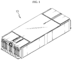
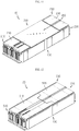
- FIG. 1 is a diagram for illustrating a battery module according to an embodiment of the present disclosure
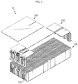
- FIG. 2 is an exploded perspective view showing the battery module of FIG. 1
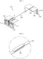
- FIG. 3 is a diagram for illustrating a bus bar unit of the battery module of FIG. 2
- FIG. 4 is an enlarged view showing a portion A of the bus bar unit of FIG. 3
- FIG. 5 is an enlarged view showing a portion B of the bus bar unit of FIG. 3 .
- the battery module 10 may include a battery cell 100, a bus bar unit 200 and a reinforcing plate 300.
- the battery cell 100 is a secondary battery, which may be a pouch-type secondary battery.
- the battery cell 100 may be provided in plural, and the plurality of battery cells 100 may be stacked one another to be electrically connected to each other.
- Each of the plurality of battery cells 100 may include an electrode assembly, a battery case and an electrode lead 150.
- the electrode assembly may include a positive electrode plate, a negative electrode plate, a separator and the like.
- the electrode assembly is well known in the art and thus is not described in detail here.
- the battery case is used for packaging the electrode assembly and may be made of a laminate sheet containing a resin layer and a metal layer.
- the electrode lead 150 may be electrically connected to the electrode assembly.
- the electrode lead 150 may be provided in a pair.
- the pair of electrode leads may partially protrude in the front and rear directions of the battery module 10.
- the bus bar unit 200 may electrically connect the electrode leads 150 of the plurality of battery cells 100 and sense voltages of the plurality of battery cells 100.
- the bus bar unit 200 may be a single unit integrally assembled and integrally connect the electrode leads 150 of the plurality of battery cells 100.
- the bus bar unit 200 may include a first bus bar frame 210, a first bus bar 220, a second bus bar frame 230, a second bus bar 240, a sensing bus bar 250 and a thermistor 260.
- the first bus bar frame 210 may be mounted in front of the plurality of battery cells 100 and cover the front side of the plurality of battery cells 100.
- the first bus bar frame 210 may include a bus bar mounting portion 212 and a cell covering portion 216.
- the bus bar mounting portion 212 may be disposed at the front of the plurality of battery cells 100.
- the first bus bar 220 explained later, may be mounted to the bus bar mounting portion 212.
- the cell covering portion 216 is formed to be bent from the bus bar mounting portion 212 and may cover a part of one surface of the plurality of battery cells 100 in the front and rear directions, in more detail a part of an upper surface of the plurality of battery cells 100.
- the first bus bar 220 is coupled to the first bus bar frame 210, in more detail to the bus bar mounting portion 212 of the first bus bar frame 210, and may be electrically connected to the electrode leads 150 which protrude to the front of the plurality of battery cells 100.
- the first bus bar 220 may be fixed to the bus bar mounting portion 212 by thermal bonding or the like.
- the second bus bar frame 230 is mounted behind the plurality of battery cells 100 and may cover the rear side of the plurality of battery cells 100.
- the second bus bar frame 230 may include a bus bar mounting portion 232 and a cell covering portion 236.
- the bus bar mounting portion 232 may be disposed at the rear of the plurality of battery cells 100.
- the second bus bar 240 explained later, may be mounted to the bus bar mounting portion 232.
- the cell covering portion 236 is formed to be bent from the bus bar mounting portion 232 and may cover a part of one surface of the plurality of battery cells 100 in the front and rear directions, in more detail a part of an upper surface of the plurality of battery cells 100.
- the second bus bar 240 is coupled to the second bus bar frame 230, in more detail to the bus bar mounting portion 232 of the second bus bar frame 230, and may be electrically coupled to the electrode leads 150 which protrude to the rear of the plurality of battery cells 100.
- the second bus bar 240 may be fixed to the bus bar mounting portion 232 by thermal bonding or the like.
- the sensing bus bar 250 may electrically connect the first bus bar 220 and the second bus bar 240 and be integrally mounted to the first bus bar 220 and the second bus bar 240, respectively.
- the sensing bus bar 250 may be any one selected from a flexible circuit board, a flexible flat cable and a wire and be disposed at the upper side of the plurality of battery cells 100.
- An elastic bending portion 255 may be provided at the sensing bus bar 250.
- the elastic bending portion 255 is provided at one side of the sensing bus bar 250 in the length direction and may be elastically bendable along the front and rear directions of the plurality of battery cells 100.
- the length of the sensing bus bar 250 may be shortened in the front and rear directions of the plurality of battery cells 100.
- the elastic bending portion 255 may be bent in at least two stages.
- the elastic bending portion 255 will be described in more detail in association with the sensing bus bar 250.
- the sensing bus bar 250 Before being mounted to the upper side of the plurality of battery cells 100, the sensing bus bar 250 may be formed longer than the length of the plurality of battery cells 100 in the front and rear directions. This allows the first bus bar frame 210 and the second bus bar frame 230 to be mounted to the plurality of battery cells 100 more easily.
- the elastic bending portion 255 may be bent so that the length of the sensing bus bar 250 corresponds to the length of the plurality of battery cells 100 in the front and rear directions. This allows the other bus bar frame, not yet completely mounted, to be mounted easily. This will be explained in more detail later with reference to FIGS. 6 to 11 which depict a process of assembling the bus bar unit 200 of the battery module 10.
- the thermistor 260 is a temperature sensor capable of detecting the temperature of the plurality of battery cells 100 and may be integrally mounted to the sensing bus bar 250.
- the thermistor 260 may be provided in a pair and integrally coupled to the sensing bus bar 250, respectively.
- the reinforcing plate 300 is provided between the first bus bar frame 210 and the second bus bar frame 230 and may cover one surface of the plurality of battery cells 100, in more detail an upper surface of the plurality of battery cells 100 between the first bus bar frame 210 and the second bus bar frame 230.
- the reinforcing plate 300 covers a region of the plurality of battery cells 100 which is not covered, and may support the plurality of battery cells 100 and give a buffering action against impacts or the like.
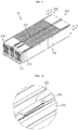
- FIGS. 6 to 11 are diagrams for illustrating a process of assembling the bus bar unit of the battery module of FIG. 1
- the bus bar unit 200 may be mounted to the plurality of battery cells 100.
- the first bus bar frame 210, the first bus bar 220, the second bus bar frame 230, the second bus bar 240, the sensing bus bar 250 and the thermistor 260 of the bus bar unit 200 may be coupled to each other to form an integrated module unit, before being mounted to the plurality of battery cells 100.
- the bus bar unit 200 may be prepared as an integrated module in advance, without preparing the components individually.
- the time required for the assembling process may be shortened, compared with the conventional structure where individual components are prepared and mounted individually for connecting and sensing the bus bars of the battery cells 100.
- bus bar unit 200 since the bus bar unit 200 is provided as an integrated module, the possibility of erroneous assembling in the assembling direction, caused by individual assembling of individual components, may be significantly lowered. In addition, since it is not needed to apply individual molds for individual components and package individual components, the manufacturing cost may be greatly reduced.
- any one of the first bus bar frame 210 and the second bus bar frame 230 of the bus bar unit 200 may be mounted to the front or rear of the plurality of battery cells 100.
- the first bus bar frame 210 of the bus bar unit 200 may be mounted to the front of the plurality of battery cells 100 firstly.
- the first bus bar 220 may be connected to the electrode leads 150 which protrude to the front of the plurality of battery cells 100.
- the elastic bending portion 255 of the sensing bus bar 250 may be disposed without being bent in at least two stages.
- the total length of the sensing bus bar 250 may be longer than the length of the plurality of battery cells 100 in the front and rear directions. Accordingly, the second bus bar frame 230 may be disposed to be spaced apart from the rear side of the plurality of battery cells 100 without interfering with the rear surface of the plurality of battery cells 100 or the electrode leads 150.
- any one of the first bus bar frame 210 and the second bus bar frame 230 is mounted to the plurality of battery cells 100, the other one of the first bus bar frame 210 and the second bus bar frame 230 may be slidably mounted along the front and rear directions of the plurality of battery cells 100.
- the second bus bar frame 230 may slide in the front direction of the battery cells 100.
- the elastic bending portion 255 of the sensing bus bar 250 may elastically bent to reduce the total length of the sensing bus bar 250 in the front and rear directions of the battery cells 100.
- the second bus bar frame 230 may be closely adhered to the rear side of the plurality of battery cells 100, and the second bus bar 240 may be electrically connected to the electrode leads 150 which protrude to the rear of the plurality of battery cells 100.
- the bus bar unit 200 may integrally connect the electrode leads 150 of the plurality of battery cells 100 and perform connection for voltage sensing at the same time.
- the reinforcing plate 300 may cover the upper surface of the plurality of battery cells 100 between the first bus bar frame 210 and the second bus bar frame 230 of the bus bar unit 200.
- the battery module 10 of this embodiment may greatly improve the assembling efficiency of the battery module 10 by using the bus bar unit 200 which is prepared as an integrated module.
- FIG. 12 is a diagram for illustrating a battery module according to another embodiment of the present disclosure
- FIG. 13 is a diagram for illustrating a process of assembling the bus bar unit of the battery module of FIG. 12 .
- the battery module 20 may include the plurality of battery cells 100 and a bus bar unit 500.
- the bus bar unit 500 is similar to the bus bar unit 200 of the former embodiment, and thus its features different from those of the bus bar unit 200 will be described in detail.
- a cell covering portion 516 of a first bus bar frame 510 and a cell covering portion 536 of a second bus bar frame 530 may be shaped to correspond to each other in the front and rear directions of the plurality of battery cells 100.
- the cell covering portion 516 of the first bus bar frame 510 and the cell covering portion 536 of the second bus bar frame 530 may be engaged with each other to cover one surface of the plurality of battery cells 100, in more detail the upper surface of the plurality of battery cells 100, entirely.
- the battery module 20 of this embodiment may cover the upper surface of the plurality of battery cells 100 entirely by means of the first bus bar frame 510 and the second bus bar frame 530 which are engaged with each other, without using the reinforcing plate 300 of the former embodiment.
- the battery module 20 of this embodiment does not demand a separate reinforcing plate, different from the former embodiment, and thus it is possible to reduce the manufacture cost of the battery module 20 further and improve the assembling efficiency further.
- FIG. 14 is a diagram for illustrating a battery pack according to an embodiment of the present disclosure.
- a battery pack 1 may include at least one battery module 10, 20 according to the former embodiment and a pack case 50 for packaging the at least one battery module 10, 20.
- the battery pack 1 may be provided to a vehicle as a fuel source of the vehicle.
- the battery pack 1 may be provided to an electric vehicle, a hybrid vehicle, and various other-type vehicles capable of using the battery pack 1 as a fuel source.
- the battery pack 1 may be provided in other devices, instruments or facilities such as an energy storage system using a secondary battery, in addition to the vehicle.
- the battery pack 1 of this embodiment and devices, instruments or facilities such as a vehicle, which have the battery pack 1 include the battery module 10, 20 as described above, and thus it is possible to implement a battery pack 1 having all the advantages of the battery module 10, 20 described above, or devices, instruments, facilities or the like such as a vehicle, which have the battery pack 1.
Landscapes
- Engineering & Computer Science (AREA)
- Chemical & Material Sciences (AREA)
- General Chemical & Material Sciences (AREA)
- Electrochemistry (AREA)
- Chemical Kinetics & Catalysis (AREA)
- Sustainable Energy (AREA)
- Mechanical Engineering (AREA)
- Transportation (AREA)
- Power Engineering (AREA)
- Life Sciences & Earth Sciences (AREA)
- Sustainable Development (AREA)
- Manufacturing & Machinery (AREA)
- Battery Mounting, Suspending (AREA)
- Connection Of Batteries Or Terminals (AREA)
Priority Applications (1)
| Application Number | Priority Date | Filing Date | Title |
|---|---|---|---|
| PL17858592T PL3389113T3 (pl) | 2016-10-06 | 2017-07-28 | Moduł akumulatorowy, pakiet akumulatorowy zawierający moduł akumulatorowy i pojazd zawierający pakiet akumulatorowy |
Applications Claiming Priority (2)
| Application Number | Priority Date | Filing Date | Title |
|---|---|---|---|
| KR1020160129118A KR102102927B1 (ko) | 2016-10-06 | 2016-10-06 | 배터리 모듈, 이러한 배터리 모듈을 포함하는 배터리 팩 및 이러한 배터리 팩을 포함하는 자동차 |
| PCT/KR2017/008191 WO2018066797A1 (ko) | 2016-10-06 | 2017-07-28 | 배터리 모듈, 이러한 배터리 모듈을 포함하는 배터리 팩 및 이러한 배터리 팩을 포함하는 자동차 |
Publications (3)
| Publication Number | Publication Date |
|---|---|
| EP3389113A1 true EP3389113A1 (de) | 2018-10-17 |
| EP3389113A4 EP3389113A4 (de) | 2019-04-10 |
| EP3389113B1 EP3389113B1 (de) | 2020-03-04 |
Family
ID=61832010
Family Applications (1)
| Application Number | Title | Priority Date | Filing Date |
|---|---|---|---|
| EP17858592.3A Active EP3389113B1 (de) | 2016-10-06 | 2017-07-28 | Batteriemodul, batteriepack mit batteriemodul, und fahrzeug mit batteriepack |
Country Status (7)
| Country | Link |
|---|---|
| US (2) | US10981454B2 (de) |
| EP (1) | EP3389113B1 (de) |
| JP (1) | JP6692917B2 (de) |
| KR (1) | KR102102927B1 (de) |
| CN (1) | CN108463902B (de) |
| PL (1) | PL3389113T3 (de) |
| WO (1) | WO2018066797A1 (de) |
Cited By (4)
| Publication number | Priority date | Publication date | Assignee | Title |
|---|---|---|---|---|
| CN112119517A (zh) * | 2018-12-26 | 2020-12-22 | 株式会社Lg化学 | 具有用于限制汇流条框架的移动的引导件的电池模块、以及包括该电池模块的电池组和车辆 |
| EP3761393A4 (de) * | 2018-12-26 | 2021-06-16 | Lg Chem, Ltd. | Batteriemodul mit innenabdeckung |
| US20230261328A1 (en) * | 2022-02-15 | 2023-08-17 | Polestar Performance Ab | Structurally supportive electric vehicle battery busbar |
| EP4376200A4 (de) * | 2022-07-20 | 2025-04-09 | LG Energy Solution, Ltd. | Batteriepack, batteriemodul und fahrzeug damit |
Families Citing this family (59)
| Publication number | Priority date | Publication date | Assignee | Title |
|---|---|---|---|---|
| JP6940452B2 (ja) * | 2018-04-18 | 2021-09-29 | 株式会社オートネットワーク技術研究所 | 配線モジュール |
| KR102328730B1 (ko) | 2018-04-20 | 2021-11-17 | 주식회사 엘지에너지솔루션 | 직/병렬 연결을 용이하게 하는 구조를 갖는 배터리 모듈 및 이를 포함하는 배터리 팩 |
| KR102354401B1 (ko) * | 2018-04-25 | 2022-01-20 | 주식회사 엘지에너지솔루션 | 배터리 모듈 및 이를 포함하는 배터리 팩 |
| KR102670297B1 (ko) | 2018-07-26 | 2024-05-30 | 주식회사 엘지에너지솔루션 | 버스바 조립체 |
| KR102352686B1 (ko) * | 2018-09-28 | 2022-01-17 | 주식회사 엘지에너지솔루션 | 배터리 모듈, 이러한 배터리 모듈을 포함하는 배터리 팩 및 이러한 배터리 팩을 포함하는 자동차 |
| KR102395228B1 (ko) * | 2018-10-10 | 2022-05-04 | 주식회사 엘지에너지솔루션 | 버스바 프레임 조립 방법 |
| KR102250193B1 (ko) * | 2018-10-10 | 2021-05-07 | 주식회사 엘지화학 | 공간 절약형 icb 조립체를 적용한 배터리 모듈 |
| KR102646854B1 (ko) * | 2018-10-19 | 2024-03-11 | 삼성에스디아이 주식회사 | 배터리 모듈 |
| KR102646853B1 (ko) | 2018-10-19 | 2024-03-11 | 삼성에스디아이 주식회사 | 배터리 모듈 |
| KR102717207B1 (ko) | 2018-10-19 | 2024-10-11 | 삼성에스디아이 주식회사 | 배터리 모듈 |
| KR102640329B1 (ko) | 2018-10-19 | 2024-02-22 | 삼성에스디아이 주식회사 | 배터리 모듈 |
| KR102640327B1 (ko) | 2018-10-19 | 2024-02-22 | 삼성에스디아이 주식회사 | 배터리의 대형 모듈 |
| KR102700560B1 (ko) | 2018-11-19 | 2024-08-28 | 주식회사 엘지에너지솔루션 | 센싱 어셈블리 장착용 지그 및 이를 이용한 배터리 모듈의 조립 방법 |
| KR102349918B1 (ko) * | 2018-11-21 | 2022-01-10 | 주식회사 엘지에너지솔루션 | 배터리 모듈 |
| KR102317638B1 (ko) | 2018-12-05 | 2021-10-25 | 주식회사 엘지에너지솔루션 | 셀 적층체의 보호 구조를 갖는 배터리 모듈 |
| KR102367381B1 (ko) | 2018-12-26 | 2022-02-23 | 주식회사 엘지에너지솔루션 | 이물질 유입 방지 구조를 갖는 배터리 모듈, 이를 포함하는 배터리 팩 및 자동차 |
| KR102379227B1 (ko) * | 2018-12-26 | 2022-03-24 | 주식회사 엘지에너지솔루션 | 배터리 모듈, 이러한 배터리 모듈을 포함하는 배터리 팩 및 이러한 배터리 팩을 포함하는 자동차 |
| KR102395683B1 (ko) * | 2018-12-26 | 2022-05-06 | 주식회사 엘지에너지솔루션 | Fpcb에 실장된 커넥터를 구비하는 배터리 모듈, 이를 포함하는 배터리 팩 및 자동차 |
| KR102825806B1 (ko) | 2019-02-08 | 2025-06-25 | 에스케이온 주식회사 | 배터리 모듈 |
| KR102381762B1 (ko) * | 2019-02-21 | 2022-03-31 | 주식회사 엘지에너지솔루션 | 연성 인쇄 회로 기판을 덮는 보호 커버를 포함하는 전지 모듈 |
| KR102722638B1 (ko) * | 2019-03-26 | 2024-10-25 | 주식회사 엘지에너지솔루션 | 전지 모듈 및 그 제조 방법 |
| KR102466503B1 (ko) * | 2019-06-11 | 2022-11-10 | 주식회사 엘지에너지솔루션 | 전지 모듈 및 그 제조 방법 |
| KR102439229B1 (ko) | 2019-06-12 | 2022-08-31 | 주식회사 엘지에너지솔루션 | 전지 모듈, 그 제조 방법 및 전지 모듈을 포함하는 전지 팩 |
| JP7025376B2 (ja) * | 2019-06-17 | 2022-02-24 | 矢崎総業株式会社 | バスバモジュール |
| KR102503536B1 (ko) * | 2019-06-18 | 2023-02-23 | 주식회사 엘지에너지솔루션 | 전지 모듈 및 이를 포함하는 전지팩 |
| KR102691429B1 (ko) * | 2019-06-18 | 2024-08-01 | 주식회사 엘지에너지솔루션 | 전지 모듈 및 이를 포함하는 전지팩 |
| KR102541537B1 (ko) * | 2019-06-25 | 2023-06-08 | 주식회사 엘지에너지솔루션 | 전지 모듈 및 이를 포함하는 전지팩 |
| KR102464824B1 (ko) * | 2019-06-25 | 2022-11-07 | 주식회사 엘지에너지솔루션 | 전지 모듈 및 이를 포함하는 전지 팩 |
| JP7437890B2 (ja) * | 2019-07-23 | 2024-02-26 | 日本メクトロン株式会社 | バッテリ用配線部材及びバッテリ装置 |
| KR102473336B1 (ko) | 2019-10-07 | 2022-12-01 | 주식회사 엘지에너지솔루션 | 전지 모듈 및 이를 포함하는 전지팩 |
| KR102464825B1 (ko) * | 2019-10-10 | 2022-11-07 | 주식회사 엘지에너지솔루션 | 전지 모듈 및 이를 포함하는 전지팩 |
| KR102809759B1 (ko) * | 2019-10-14 | 2025-05-16 | 주식회사 엘지에너지솔루션 | 배터리 셀, 이러한 배터리 셀을 포함하는 배터리 모듈 및 이러한 배터리 모듈을 포함하는 배터리 팩 |
| KR102798546B1 (ko) | 2019-10-18 | 2025-04-18 | 주식회사 엘지에너지솔루션 | 전지 모듈 |
| KR20210051723A (ko) * | 2019-10-31 | 2021-05-10 | 에스케이이노베이션 주식회사 | 센싱 조립체 및 이를 포함하는 배터리 모듈 |
| KR102792210B1 (ko) * | 2019-12-05 | 2025-04-04 | 주식회사 엘지에너지솔루션 | 전지 모듈 및 이를 포함하는 전지 팩 |
| KR102772767B1 (ko) * | 2020-01-03 | 2025-02-24 | 주식회사 엘지에너지솔루션 | 전지 모듈 및 이를 포함하는 전지팩 |
| US20230202345A1 (en) * | 2020-01-23 | 2023-06-29 | Sanyo Electric Co., Ltd. | Power supply device, and electric vehicle and power storage device equipped with this power supply device |
| KR102862773B1 (ko) * | 2020-02-17 | 2025-09-19 | 주식회사 엘지에너지솔루션 | 배터리 모듈, 이러한 배터리 모듈을 포함하는 배터리 팩 및 자동차 |
| KR102858181B1 (ko) * | 2020-02-27 | 2025-09-10 | 주식회사 엘지에너지솔루션 | 신속한 냉각이 가능한 구조를 갖는 배터리 모듈 및 이를 포함하는 ess |
| KR102837601B1 (ko) * | 2020-03-05 | 2025-07-22 | 주식회사 엘지에너지솔루션 | 전지 모듈 및 이를 포함하는 전지팩 |
| KR102640844B1 (ko) * | 2020-04-14 | 2024-02-27 | 삼성에스디아이 주식회사 | 배터리 팩 |
| KR102890289B1 (ko) | 2020-04-29 | 2025-11-21 | 주식회사 엘지에너지솔루션 | 전지 모듈 및 이를 포함하는 전지팩 |
| KR102890288B1 (ko) * | 2020-04-29 | 2025-11-21 | 주식회사 엘지에너지솔루션 | 전지 모듈 및 이를 포함하는 전지팩 |
| US12506227B2 (en) * | 2020-07-14 | 2025-12-23 | Autonetworks Technologies, Ltd. | Wiring module |
| JP7413943B2 (ja) | 2020-07-14 | 2024-01-16 | 株式会社オートネットワーク技術研究所 | 配線モジュール |
| KR102851455B1 (ko) * | 2020-10-14 | 2025-08-26 | 주식회사 엘지에너지솔루션 | 전지 모듈 및 이를 포함하는 전지 팩 |
| KR102860571B1 (ko) | 2020-10-14 | 2025-09-15 | 주식회사 엘지에너지솔루션 | 전지 모듈 및 그 제조 방법 |
| KR20220065601A (ko) * | 2020-11-13 | 2022-05-20 | 주식회사 엘지에너지솔루션 | 스웰링 제어가 가능한 구조를 갖는 배터리 팩 및 이를 포함하는 자동차 |
| KR20230015765A (ko) * | 2021-07-23 | 2023-01-31 | 현대자동차주식회사 | 배터리 모듈 |
| US12463283B2 (en) | 2021-10-12 | 2025-11-04 | Lg Energy Solution, Ltd. | Battery pack and vehicle including the same |
| US20230113884A1 (en) * | 2021-10-12 | 2023-04-13 | Lg Energy Solution, Ltd. | Battery pack and vehicle including the same |
| CN216529247U (zh) * | 2021-11-24 | 2022-05-13 | 比亚迪股份有限公司 | 一种电芯单元、电池和汽车 |
| EP4391189A4 (de) * | 2022-04-15 | 2025-04-02 | LG Energy Solution, Ltd. | Batteriemodul mit erhöhter sicherheit |
| US20240118079A1 (en) * | 2022-10-05 | 2024-04-11 | Stanley Black & Decker Inc. | Construction laser level |
| EP4468499A4 (de) * | 2022-12-05 | 2025-06-18 | LG Energy Solution, Ltd. | Batteriemodul sowie batteriepack und fahrzeug damit |
| EP4465431A4 (de) * | 2022-12-08 | 2025-06-04 | LG Energy Solution, Ltd. | Batteriemodul sowie batteriepack und fahrzeug damit |
| KR20240154199A (ko) * | 2023-04-18 | 2024-10-25 | 주식회사 엘지에너지솔루션 | 버스바 자동조립 지그 및 이를 이용한 배터리 모듈의 제조방법 |
| JP7713492B2 (ja) * | 2023-07-04 | 2025-07-25 | プライムプラネットエナジー&ソリューションズ株式会社 | 電池パック |
| KR20250140829A (ko) * | 2024-03-19 | 2025-09-26 | 삼성에스디아이 주식회사 | 버스바 홀더 및 배터리 모듈 |
Family Cites Families (14)
| Publication number | Priority date | Publication date | Assignee | Title |
|---|---|---|---|---|
| WO2010113455A1 (ja) * | 2009-03-31 | 2010-10-07 | 三洋電機株式会社 | 電池モジュール、バッテリシステムおよび電動車両 |
| WO2010114311A2 (ko) | 2009-04-01 | 2010-10-07 | 주식회사 엘지화학 | 안전성이 향상된 전지모듈 |
| KR101023921B1 (ko) | 2009-04-01 | 2011-03-22 | 주식회사 엘지화학 | 전압 검출부재 및 이를 포함하는 전지모듈 |
| KR20140072689A (ko) * | 2012-12-05 | 2014-06-13 | 에스케이이노베이션 주식회사 | 전지모듈 어셈블리 |
| KR102003067B1 (ko) | 2012-12-21 | 2019-07-24 | 타이코에이엠피 주식회사 | 전압 센싱 모듈 및 이를 구비하는 전지모듈 |
| KR20140095660A (ko) * | 2013-01-24 | 2014-08-04 | 엘지전자 주식회사 | 배터리 셀 케이스 및 이를 포함하는 배터리팩 |
| JP5880473B2 (ja) | 2013-02-27 | 2016-03-09 | 株式会社デンソー | 電池ユニット |
| US9553342B2 (en) * | 2013-05-16 | 2017-01-24 | Samsung Sdi Co., Ltd. | Battery pack |
| KR102046125B1 (ko) * | 2013-11-13 | 2019-11-18 | 에스케이이노베이션 주식회사 | 착탈식 전압센싱모듈 및 이를 구비한 배터리장치 |
| KR101841663B1 (ko) | 2014-03-06 | 2018-05-04 | 주식회사 엘지화학 | 리셉터클 구조의 전압 센싱부재를 포함하는 전지모듈 |
| KR101821378B1 (ko) * | 2014-03-31 | 2018-01-23 | 주식회사 엘지화학 | 전극 리드와 버스바 사이의 결합력 및 공정성이 향상된 배터리 모듈 및 이를 포함하는 배터리 팩 |
| KR101807115B1 (ko) | 2014-04-03 | 2017-12-08 | 주식회사 엘지화학 | 언더 베이스 바를 포함하는 배터리 모듈 어레이 |
| JP6315278B2 (ja) | 2014-12-25 | 2018-04-25 | 株式会社オートネットワーク技術研究所 | 蓄電モジュール |
| JP6667255B2 (ja) | 2015-10-22 | 2020-03-18 | 株式会社エンビジョンAescジャパン | 組電池および組電池の製造方法 |
-
2016
- 2016-10-06 KR KR1020160129118A patent/KR102102927B1/ko active Active
-
2017
- 2017-07-28 WO PCT/KR2017/008191 patent/WO2018066797A1/ko not_active Ceased
- 2017-07-28 US US16/064,196 patent/US10981454B2/en not_active Ceased
- 2017-07-28 CN CN201780006509.9A patent/CN108463902B/zh active Active
- 2017-07-28 JP JP2018546855A patent/JP6692917B2/ja active Active
- 2017-07-28 EP EP17858592.3A patent/EP3389113B1/de active Active
- 2017-07-28 PL PL17858592T patent/PL3389113T3/pl unknown
- 2017-07-28 US US18/137,346 patent/USRE50620E1/en active Active
Cited By (8)
| Publication number | Priority date | Publication date | Assignee | Title |
|---|---|---|---|---|
| CN112119517A (zh) * | 2018-12-26 | 2020-12-22 | 株式会社Lg化学 | 具有用于限制汇流条框架的移动的引导件的电池模块、以及包括该电池模块的电池组和车辆 |
| EP3761393A4 (de) * | 2018-12-26 | 2021-06-16 | Lg Chem, Ltd. | Batteriemodul mit innenabdeckung |
| EP3836246A4 (de) * | 2018-12-26 | 2021-10-27 | LG Chem, Ltd. | Batteriemodul mit führung zur begrenzung der bewegung eines sammelschienenrahmens sowie batteriepack und fahrzeug damit |
| CN112119517B (zh) * | 2018-12-26 | 2023-01-10 | 株式会社Lg新能源 | 电池模块、包括该电池模块的电池组和车辆 |
| US11973244B2 (en) | 2018-12-26 | 2024-04-30 | Lg Energy Solution, Ltd. | Battery module having guide for restricting movement of busbar frame, and battery pack and vehicle comprising same |
| US20230261328A1 (en) * | 2022-02-15 | 2023-08-17 | Polestar Performance Ab | Structurally supportive electric vehicle battery busbar |
| US12160018B2 (en) * | 2022-02-15 | 2024-12-03 | Polestar Performance Ab | Structurally supportive electric vehicle battery busbar |
| EP4376200A4 (de) * | 2022-07-20 | 2025-04-09 | LG Energy Solution, Ltd. | Batteriepack, batteriemodul und fahrzeug damit |
Also Published As
| Publication number | Publication date |
|---|---|
| US20190001838A1 (en) | 2019-01-03 |
| US10981454B2 (en) | 2021-04-20 |
| CN108463902A (zh) | 2018-08-28 |
| EP3389113A4 (de) | 2019-04-10 |
| WO2018066797A1 (ko) | 2018-04-12 |
| CN108463902B (zh) | 2021-03-16 |
| USRE50620E1 (en) | 2025-10-07 |
| EP3389113B1 (de) | 2020-03-04 |
| JP2019511810A (ja) | 2019-04-25 |
| PL3389113T3 (pl) | 2020-07-13 |
| KR102102927B1 (ko) | 2020-04-21 |
| KR20180038253A (ko) | 2018-04-16 |
| JP6692917B2 (ja) | 2020-05-13 |
Similar Documents
| Publication | Publication Date | Title |
|---|---|---|
| US10981454B2 (en) | Battery module, battery pack including battery module, and vehicle including battery pack | |
| US11285821B2 (en) | Battery module, battery pack comprising battery module, and vehicle comprising battery pack | |
| US12261326B2 (en) | Battery module, battery pack including same battery module, and automobile including same battery pack | |
| EP3836244B1 (de) | Batteriemodul und batteriepack mit dem batteriemodul | |
| US11108091B2 (en) | Battery module, and battery pack and energy storage system including the same | |
| EP3561902B1 (de) | Batteriemodul, batteriepack mit dem batteriemodul und fahrzeug mit dem batteriepack | |
| EP3336928A1 (de) | Batteriemodul, batteriepack mit dem batteriemodul und fahrzeug mit dem batteriepack | |
| US11456502B2 (en) | Battery module, battery pack comprising same battery module, and vehicle comprising same battery pack | |
| AU2020224504B2 (en) | Battery cell, and battery module, battery rack and energy storage system including the same | |
| KR20150142790A (ko) | 스웰링 현상에 의한 배터리 모듈의 외형 변화를 방지할 수 있는 배터리 모듈 어셈블리용 엔드 플레이트 및 이를 포함하는 배터리 팩 |
Legal Events
| Date | Code | Title | Description |
|---|---|---|---|
| STAA | Information on the status of an ep patent application or granted ep patent |
Free format text: STATUS: THE INTERNATIONAL PUBLICATION HAS BEEN MADE |
|
| PUAI | Public reference made under article 153(3) epc to a published international application that has entered the european phase |
Free format text: ORIGINAL CODE: 0009012 |
|
| STAA | Information on the status of an ep patent application or granted ep patent |
Free format text: STATUS: REQUEST FOR EXAMINATION WAS MADE |
|
| 17P | Request for examination filed |
Effective date: 20180713 |
|
| AK | Designated contracting states |
Kind code of ref document: A1 Designated state(s): AL AT BE BG CH CY CZ DE DK EE ES FI FR GB GR HR HU IE IS IT LI LT LU LV MC MK MT NL NO PL PT RO RS SE SI SK SM TR |
|
| AX | Request for extension of the european patent |
Extension state: BA ME |
|
| A4 | Supplementary search report drawn up and despatched |
Effective date: 20190313 |
|
| RIC1 | Information provided on ipc code assigned before grant |
Ipc: H01M 2/20 20060101ALI20190306BHEP Ipc: H01M 2/10 20060101AFI20190306BHEP Ipc: H01M 10/48 20060101ALI20190306BHEP |
|
| GRAP | Despatch of communication of intention to grant a patent |
Free format text: ORIGINAL CODE: EPIDOSNIGR1 |
|
| STAA | Information on the status of an ep patent application or granted ep patent |
Free format text: STATUS: GRANT OF PATENT IS INTENDED |
|
| RIC1 | Information provided on ipc code assigned before grant |
Ipc: H01M 10/48 20060101ALI20191112BHEP Ipc: H01M 2/20 20060101ALI20191112BHEP Ipc: H01M 2/10 20060101AFI20191112BHEP Ipc: B60L 50/50 20190101ALI20191112BHEP |
|
| INTG | Intention to grant announced |
Effective date: 20191129 |
|
| DAV | Request for validation of the european patent (deleted) | ||
| DAX | Request for extension of the european patent (deleted) | ||
| GRAS | Grant fee paid |
Free format text: ORIGINAL CODE: EPIDOSNIGR3 |
|
| GRAA | (expected) grant |
Free format text: ORIGINAL CODE: 0009210 |
|
| STAA | Information on the status of an ep patent application or granted ep patent |
Free format text: STATUS: THE PATENT HAS BEEN GRANTED |
|
| AK | Designated contracting states |
Kind code of ref document: B1 Designated state(s): AL AT BE BG CH CY CZ DE DK EE ES FI FR GB GR HR HU IE IS IT LI LT LU LV MC MK MT NL NO PL PT RO RS SE SI SK SM TR |
|
| REG | Reference to a national code |
Ref country code: GB Ref legal event code: FG4D |
|
| REG | Reference to a national code |
Ref country code: CH Ref legal event code: EP |
|
| REG | Reference to a national code |
Ref country code: AT Ref legal event code: REF Ref document number: 1241401 Country of ref document: AT Kind code of ref document: T Effective date: 20200315 |
|
| REG | Reference to a national code |
Ref country code: DE Ref legal event code: R096 Ref document number: 602017012730 Country of ref document: DE |
|
| REG | Reference to a national code |
Ref country code: IE Ref legal event code: FG4D |
|
| PG25 | Lapsed in a contracting state [announced via postgrant information from national office to epo] |
Ref country code: FI Free format text: LAPSE BECAUSE OF FAILURE TO SUBMIT A TRANSLATION OF THE DESCRIPTION OR TO PAY THE FEE WITHIN THE PRESCRIBED TIME-LIMIT Effective date: 20200304 Ref country code: NO Free format text: LAPSE BECAUSE OF FAILURE TO SUBMIT A TRANSLATION OF THE DESCRIPTION OR TO PAY THE FEE WITHIN THE PRESCRIBED TIME-LIMIT Effective date: 20200604 Ref country code: RS Free format text: LAPSE BECAUSE OF FAILURE TO SUBMIT A TRANSLATION OF THE DESCRIPTION OR TO PAY THE FEE WITHIN THE PRESCRIBED TIME-LIMIT Effective date: 20200304 |
|
| REG | Reference to a national code |
Ref country code: NL Ref legal event code: MP Effective date: 20200304 |
|
| PG25 | Lapsed in a contracting state [announced via postgrant information from national office to epo] |
Ref country code: GR Free format text: LAPSE BECAUSE OF FAILURE TO SUBMIT A TRANSLATION OF THE DESCRIPTION OR TO PAY THE FEE WITHIN THE PRESCRIBED TIME-LIMIT Effective date: 20200605 Ref country code: BG Free format text: LAPSE BECAUSE OF FAILURE TO SUBMIT A TRANSLATION OF THE DESCRIPTION OR TO PAY THE FEE WITHIN THE PRESCRIBED TIME-LIMIT Effective date: 20200604 Ref country code: LV Free format text: LAPSE BECAUSE OF FAILURE TO SUBMIT A TRANSLATION OF THE DESCRIPTION OR TO PAY THE FEE WITHIN THE PRESCRIBED TIME-LIMIT Effective date: 20200304 Ref country code: SE Free format text: LAPSE BECAUSE OF FAILURE TO SUBMIT A TRANSLATION OF THE DESCRIPTION OR TO PAY THE FEE WITHIN THE PRESCRIBED TIME-LIMIT Effective date: 20200304 Ref country code: HR Free format text: LAPSE BECAUSE OF FAILURE TO SUBMIT A TRANSLATION OF THE DESCRIPTION OR TO PAY THE FEE WITHIN THE PRESCRIBED TIME-LIMIT Effective date: 20200304 |
|
| REG | Reference to a national code |
Ref country code: LT Ref legal event code: MG4D |
|
| PG25 | Lapsed in a contracting state [announced via postgrant information from national office to epo] |
Ref country code: NL Free format text: LAPSE BECAUSE OF FAILURE TO SUBMIT A TRANSLATION OF THE DESCRIPTION OR TO PAY THE FEE WITHIN THE PRESCRIBED TIME-LIMIT Effective date: 20200304 |
|
| PG25 | Lapsed in a contracting state [announced via postgrant information from national office to epo] |
Ref country code: PT Free format text: LAPSE BECAUSE OF FAILURE TO SUBMIT A TRANSLATION OF THE DESCRIPTION OR TO PAY THE FEE WITHIN THE PRESCRIBED TIME-LIMIT Effective date: 20200729 Ref country code: SK Free format text: LAPSE BECAUSE OF FAILURE TO SUBMIT A TRANSLATION OF THE DESCRIPTION OR TO PAY THE FEE WITHIN THE PRESCRIBED TIME-LIMIT Effective date: 20200304 Ref country code: IS Free format text: LAPSE BECAUSE OF FAILURE TO SUBMIT A TRANSLATION OF THE DESCRIPTION OR TO PAY THE FEE WITHIN THE PRESCRIBED TIME-LIMIT Effective date: 20200704 Ref country code: SM Free format text: LAPSE BECAUSE OF FAILURE TO SUBMIT A TRANSLATION OF THE DESCRIPTION OR TO PAY THE FEE WITHIN THE PRESCRIBED TIME-LIMIT Effective date: 20200304 Ref country code: EE Free format text: LAPSE BECAUSE OF FAILURE TO SUBMIT A TRANSLATION OF THE DESCRIPTION OR TO PAY THE FEE WITHIN THE PRESCRIBED TIME-LIMIT Effective date: 20200304 Ref country code: RO Free format text: LAPSE BECAUSE OF FAILURE TO SUBMIT A TRANSLATION OF THE DESCRIPTION OR TO PAY THE FEE WITHIN THE PRESCRIBED TIME-LIMIT Effective date: 20200304 Ref country code: ES Free format text: LAPSE BECAUSE OF FAILURE TO SUBMIT A TRANSLATION OF THE DESCRIPTION OR TO PAY THE FEE WITHIN THE PRESCRIBED TIME-LIMIT Effective date: 20200304 Ref country code: LT Free format text: LAPSE BECAUSE OF FAILURE TO SUBMIT A TRANSLATION OF THE DESCRIPTION OR TO PAY THE FEE WITHIN THE PRESCRIBED TIME-LIMIT Effective date: 20200304 Ref country code: CZ Free format text: LAPSE BECAUSE OF FAILURE TO SUBMIT A TRANSLATION OF THE DESCRIPTION OR TO PAY THE FEE WITHIN THE PRESCRIBED TIME-LIMIT Effective date: 20200304 |
|
| REG | Reference to a national code |
Ref country code: AT Ref legal event code: MK05 Ref document number: 1241401 Country of ref document: AT Kind code of ref document: T Effective date: 20200304 |
|
| REG | Reference to a national code |
Ref country code: DE Ref legal event code: R079 Ref document number: 602017012730 Country of ref document: DE Free format text: PREVIOUS MAIN CLASS: H01M0002100000 Ipc: H01M0050200000 |
|
| REG | Reference to a national code |
Ref country code: DE Ref legal event code: R097 Ref document number: 602017012730 Country of ref document: DE |
|
| PLBE | No opposition filed within time limit |
Free format text: ORIGINAL CODE: 0009261 |
|
| STAA | Information on the status of an ep patent application or granted ep patent |
Free format text: STATUS: NO OPPOSITION FILED WITHIN TIME LIMIT |
|
| PG25 | Lapsed in a contracting state [announced via postgrant information from national office to epo] |
Ref country code: IT Free format text: LAPSE BECAUSE OF FAILURE TO SUBMIT A TRANSLATION OF THE DESCRIPTION OR TO PAY THE FEE WITHIN THE PRESCRIBED TIME-LIMIT Effective date: 20200304 Ref country code: AT Free format text: LAPSE BECAUSE OF FAILURE TO SUBMIT A TRANSLATION OF THE DESCRIPTION OR TO PAY THE FEE WITHIN THE PRESCRIBED TIME-LIMIT Effective date: 20200304 Ref country code: DK Free format text: LAPSE BECAUSE OF FAILURE TO SUBMIT A TRANSLATION OF THE DESCRIPTION OR TO PAY THE FEE WITHIN THE PRESCRIBED TIME-LIMIT Effective date: 20200304 |
|
| 26N | No opposition filed |
Effective date: 20201207 |
|
| PG25 | Lapsed in a contracting state [announced via postgrant information from national office to epo] |
Ref country code: SI Free format text: LAPSE BECAUSE OF FAILURE TO SUBMIT A TRANSLATION OF THE DESCRIPTION OR TO PAY THE FEE WITHIN THE PRESCRIBED TIME-LIMIT Effective date: 20200304 Ref country code: MC Free format text: LAPSE BECAUSE OF FAILURE TO SUBMIT A TRANSLATION OF THE DESCRIPTION OR TO PAY THE FEE WITHIN THE PRESCRIBED TIME-LIMIT Effective date: 20200304 |
|
| REG | Reference to a national code |
Ref country code: CH Ref legal event code: PL |
|
| REG | Reference to a national code |
Ref country code: BE Ref legal event code: MM Effective date: 20200731 |
|
| PG25 | Lapsed in a contracting state [announced via postgrant information from national office to epo] |
Ref country code: LU Free format text: LAPSE BECAUSE OF NON-PAYMENT OF DUE FEES Effective date: 20200728 Ref country code: LI Free format text: LAPSE BECAUSE OF NON-PAYMENT OF DUE FEES Effective date: 20200731 Ref country code: CH Free format text: LAPSE BECAUSE OF NON-PAYMENT OF DUE FEES Effective date: 20200731 |
|
| PG25 | Lapsed in a contracting state [announced via postgrant information from national office to epo] |
Ref country code: BE Free format text: LAPSE BECAUSE OF NON-PAYMENT OF DUE FEES Effective date: 20200731 |
|
| PG25 | Lapsed in a contracting state [announced via postgrant information from national office to epo] |
Ref country code: IE Free format text: LAPSE BECAUSE OF NON-PAYMENT OF DUE FEES Effective date: 20200728 |
|
| PG25 | Lapsed in a contracting state [announced via postgrant information from national office to epo] |
Ref country code: TR Free format text: LAPSE BECAUSE OF FAILURE TO SUBMIT A TRANSLATION OF THE DESCRIPTION OR TO PAY THE FEE WITHIN THE PRESCRIBED TIME-LIMIT Effective date: 20200304 Ref country code: MT Free format text: LAPSE BECAUSE OF FAILURE TO SUBMIT A TRANSLATION OF THE DESCRIPTION OR TO PAY THE FEE WITHIN THE PRESCRIBED TIME-LIMIT Effective date: 20200304 Ref country code: CY Free format text: LAPSE BECAUSE OF FAILURE TO SUBMIT A TRANSLATION OF THE DESCRIPTION OR TO PAY THE FEE WITHIN THE PRESCRIBED TIME-LIMIT Effective date: 20200304 |
|
| PG25 | Lapsed in a contracting state [announced via postgrant information from national office to epo] |
Ref country code: MK Free format text: LAPSE BECAUSE OF FAILURE TO SUBMIT A TRANSLATION OF THE DESCRIPTION OR TO PAY THE FEE WITHIN THE PRESCRIBED TIME-LIMIT Effective date: 20200304 Ref country code: AL Free format text: LAPSE BECAUSE OF FAILURE TO SUBMIT A TRANSLATION OF THE DESCRIPTION OR TO PAY THE FEE WITHIN THE PRESCRIBED TIME-LIMIT Effective date: 20200304 |
|
| REG | Reference to a national code |
Ref country code: DE Ref legal event code: R081 Ref document number: 602017012730 Country of ref document: DE Owner name: LG ENERGY SOLUTION, LTD., KR Free format text: FORMER OWNER: LG CHEM. LTD., SEOUL, KR |
|
| P01 | Opt-out of the competence of the unified patent court (upc) registered |
Effective date: 20230512 |
|
| REG | Reference to a national code |
Ref country code: GB Ref legal event code: 732E Free format text: REGISTERED BETWEEN 20231026 AND 20231101 |
|
| PGFP | Annual fee paid to national office [announced via postgrant information from national office to epo] |
Ref country code: PL Payment date: 20250626 Year of fee payment: 9 |
|
| PGFP | Annual fee paid to national office [announced via postgrant information from national office to epo] |
Ref country code: GB Payment date: 20250624 Year of fee payment: 9 |
|
| PGFP | Annual fee paid to national office [announced via postgrant information from national office to epo] |
Ref country code: FR Payment date: 20250624 Year of fee payment: 9 |
|
| PGFP | Annual fee paid to national office [announced via postgrant information from national office to epo] |
Ref country code: DE Payment date: 20250624 Year of fee payment: 9 |