EP3388810A1 - Method and device for unbalance detection - Google Patents
Method and device for unbalance detection Download PDFInfo
- Publication number
- EP3388810A1 EP3388810A1 EP18165982.2A EP18165982A EP3388810A1 EP 3388810 A1 EP3388810 A1 EP 3388810A1 EP 18165982 A EP18165982 A EP 18165982A EP 3388810 A1 EP3388810 A1 EP 3388810A1
- Authority
- EP
- European Patent Office
- Prior art keywords
- sensor
- rotating machine
- signals
- acceleration
- machine
- Prior art date
- Legal status (The legal status is an assumption and is not a legal conclusion. Google has not performed a legal analysis and makes no representation as to the accuracy of the status listed.)
- Granted
Links
- 238000000034 method Methods 0.000 title claims abstract description 19
- 238000001514 detection method Methods 0.000 title claims abstract description 12
- 230000001133 acceleration Effects 0.000 claims abstract description 38
- 238000011156 evaluation Methods 0.000 claims abstract description 10
- 238000013154 diagnostic monitoring Methods 0.000 claims abstract description 5
- 230000003068 static effect Effects 0.000 claims abstract description 5
- 238000012544 monitoring process Methods 0.000 claims description 9
- 238000012545 processing Methods 0.000 claims description 8
- 230000003750 conditioning effect Effects 0.000 claims description 6
- 238000004458 analytical method Methods 0.000 description 3
- 238000010586 diagram Methods 0.000 description 3
- 230000005284 excitation Effects 0.000 description 3
- 238000012423 maintenance Methods 0.000 description 3
- 238000004519 manufacturing process Methods 0.000 description 2
- 238000004364 calculation method Methods 0.000 description 1
- 230000001419 dependent effect Effects 0.000 description 1
- 238000011161 development Methods 0.000 description 1
- 230000018109 developmental process Effects 0.000 description 1
- 230000000694 effects Effects 0.000 description 1
- 230000005484 gravity Effects 0.000 description 1
- 230000010355 oscillation Effects 0.000 description 1
- 230000003449 preventive effect Effects 0.000 description 1
- 230000002123 temporal effect Effects 0.000 description 1
- 230000001960 triggered effect Effects 0.000 description 1
Images
Classifications
-
- G—PHYSICS
- G01—MEASURING; TESTING
- G01M—TESTING STATIC OR DYNAMIC BALANCE OF MACHINES OR STRUCTURES; TESTING OF STRUCTURES OR APPARATUS, NOT OTHERWISE PROVIDED FOR
- G01M1/00—Testing static or dynamic balance of machines or structures
- G01M1/14—Determining unbalance
- G01M1/16—Determining unbalance by oscillating or rotating the body to be tested
- G01M1/22—Determining unbalance by oscillating or rotating the body to be tested and converting vibrations due to unbalance into electric variables
-
- G—PHYSICS
- G01—MEASURING; TESTING
- G01M—TESTING STATIC OR DYNAMIC BALANCE OF MACHINES OR STRUCTURES; TESTING OF STRUCTURES OR APPARATUS, NOT OTHERWISE PROVIDED FOR
- G01M1/00—Testing static or dynamic balance of machines or structures
- G01M1/14—Determining unbalance
- G01M1/16—Determining unbalance by oscillating or rotating the body to be tested
- G01M1/28—Determining unbalance by oscillating or rotating the body to be tested with special adaptations for determining unbalance of the body in situ, e.g. of vehicle wheels
-
- G—PHYSICS
- G01—MEASURING; TESTING
- G01P—MEASURING LINEAR OR ANGULAR SPEED, ACCELERATION, DECELERATION, OR SHOCK; INDICATING PRESENCE, ABSENCE, OR DIRECTION, OF MOVEMENT
- G01P15/00—Measuring acceleration; Measuring deceleration; Measuring shock, i.e. sudden change of acceleration
- G01P15/02—Measuring acceleration; Measuring deceleration; Measuring shock, i.e. sudden change of acceleration by making use of inertia forces using solid seismic masses
- G01P15/08—Measuring acceleration; Measuring deceleration; Measuring shock, i.e. sudden change of acceleration by making use of inertia forces using solid seismic masses with conversion into electric or magnetic values
- G01P15/097—Measuring acceleration; Measuring deceleration; Measuring shock, i.e. sudden change of acceleration by making use of inertia forces using solid seismic masses with conversion into electric or magnetic values by vibratory elements
Abstract
Die Erfindung betrifft eine Vorrichtung (10) und ein Verfahren zur sensordiagnostischen Überwachung und Erkennung einer Unwucht einer rotierenden Maschine (1) in einem statischen Gehäuse (2) mit den folgenden Schritten:
a. Ermittlung von Beschleunigungssignalen (Sb) des Gehäuses (2) mit einem Sensor (20);
b. Ermittlung von Signalen (Sd) zur Drehzahlbestimmung der rotierenden Maschine (1) mittels eines zweiten Sensors;
c. Zuführen und Auswerten der Sensorsignale (Sb, Sd) mittels einer Auswerteeinheit (40, 50, 60), wobei eine mit der Drehzahl der rotierenden Maschine auftretende Beschleunigungskomponente erfasst wird und diese Komponente mit einem vorbestimmten Grenzwert vergleichen wird.

a. Determination of acceleration signals (Sb) of the housing (2) with a sensor (20);
b. Determining signals (Sd) for speed determination of the rotating machine (1) by means of a second sensor;
c. Supplying and evaluating the sensor signals (Sb, Sd) by means of an evaluation unit (40, 50, 60), whereby an acceleration component occurring with the rotational speed of the rotating machine is detected and this component is compared with a predetermined limit value.
Description
Die Erfindung betrifft ein Verfahren sowie eine Vorrichtung zur Durchführung eines Verfahrens zur sensordiagnostischen Überwachung und Erkennung einer Unwucht einer sich rotierenden Maschine.The invention relates to a method and a device for carrying out a method for sensor-diagnostic monitoring and detection of an imbalance of a rotating machine.
Im Stand der Technik sind bereits diverse Verfahren bekannt, um Diagnosen zu Fertigungsmaschinen oder Produktionsanlagen und deren zeitlichem Verhalten zu treffen. Die Anlagenverfügbarkeit einer rotierenden Maschine, wie z. B. eines Motors stellt einen wichtigen Faktor für die wirtschaftliche Nutzung dieser Einrichtung dar.In the prior art, various methods are already known to make diagnoses of manufacturing machines or production equipment and their temporal behavior. The plant availability of a rotating machine, such. As an engine is an important factor for the economic use of this device.
Die Hauptaufgabe eines Verfahren zur Überwachung des Zustandes von insbesondere rotierenden oder drehbaren Maschinen besteht darin, möglichst ohne Betriebsunterbrechung eine Beurteilung des aktuellen Maschinenzustandes, der Belastung der Maschine und jeglicher Veränderungen des Maschinenzustandes betreffend deren Rundlauf zu ermöglichen. Unter Maschinenzustand versteht man dabei u.a. die Bewertung der Unwucht der Maschine auf der Basis bestimmter Betriebsparameter.The main task of a procedure for monitoring the condition of In particular rotating or rotating machines is to allow as possible without interruption of service, an assessment of the current machine condition, the load of the machine and any changes in the machine condition regarding their concentricity. Under machine condition one understands among other things the evaluation of the imbalance of the machine on the basis of certain operating parameters.
Bei rotatorisch arbeitenden Maschinen kann es durch ungleichmäßige Masseverteilung zu einer umlaufenden radialen Kraftkomponente kommen, welche zu Vibrationen und erhöhtem Verschleiß der Maschine führt. Wünschenswert wäre es daher die sich je nach Betriebsdauer verändernde, ungleichmäßige Masseverteilung der rotierenden Komponente (Unwucht) detektieren zu können.In rotary machines, uneven mass distribution can lead to a circumferential radial force component, which leads to vibrations and increased wear of the machine. It would therefore be desirable to be able to detect the uneven mass distribution of the rotating component (imbalance) that changes depending on the operating time.
Durch vorbeugende Instandhaltung und Erfahrungswerte können die Verfügbarkeiten der rotierenden Vorrichtungen verbessert und gleichzeitig die Ausfallzeiten der rotierenden Anlagen sowie die Kosten der Instandhaltung reduziert werden. Nachteilig ist dabei, dass es selten möglich ist, genaue Vorhersagen über den aktuellen Zustand und den Rundlauf der gerade rotierenden Maschine zu treffen und daher auch keine Vorhersagen oder Erkenntnisse möglich sind, den Zeitpunkt des Ausfalls von Maschinenteilen, Lager oder Verschleißteilen zu treffen. Ferner ist die vorbeugende Instandhaltung kein geeignetes Mittel die Unwucht zu erkennen, sondern dient nur der Vermeidung von Maschinenstillstandzeiten. Allerdings ist es dadurch immer wieder der Fall, dass Teile ausgetauscht werden, die noch über eine hohe Reststandzeit verfügen und ggf. noch keine Unwucht vorhanden ist.Preventative maintenance and experience can improve the availability of rotating equipment while reducing downtime of the rotating equipment and the cost of maintenance. The disadvantage here is that it is rarely possible to make accurate predictions about the current state and the concentricity of the currently rotating machine and therefore no predictions or findings are possible to make the date of failure of machine parts, bearings or wearing parts. Furthermore, the preventive maintenance is not a suitable means to detect the imbalance, but only serves to avoid machine downtime. However, it is always the case that parts are replaced, which still have a high residual life and possibly no unbalance is present.
Eine alternative Form stellt eine zustandsbezogene und regelmäßige Ermittlung des Maschinenzustands dar. Die dafür entwickelten und im Stand der Technik verfügbaren Mess- und Auswerteverfahren dienen der Überwachung und Auswertung von Prozessparametern und Maschinenkennwerten, wie z. B. Temperatur, Druck, Drehmoment oder elektrische Stromdaten. Häufig wird auch eine Schwingungsanalyse zur Maschinendiagnose eingesetzt. Mit einer derartigen Analyse ist es möglich, eine sich durch zunehmende Unwucht erkennbare Störung bereits im Frühstadium zu erkennen und zu diagnostizieren, um Folgeschäden und Ausfallzeiten zu vermeiden.An alternative form represents a state-related and regular determination of the machine state. The measuring and evaluation methods developed for this purpose and available in the state of the art are used for monitoring and evaluating process parameters and machine parameters, such as, for example, As temperature, pressure, torque or electrical current data. Frequently, a vibration analysis is used for machine diagnostics. Such an analysis makes it possible to recognize and diagnose a disorder that can be recognized by increasing imbalance at an early stage in order to avoid consequential damage and downtimes.
So sind beispielsweise Verfahren zur Überwachung von sich kontinuierlich bewegenden und/oder rotierenden Maschinenteilen, insbesondere von Maschinenlagern, durch Analyse von Schwingungsmustern bekannt. Die dafür notwendigen Schwingungsüberwachungssysteme messen die Vibration der sich über einen längeren Zeitraum hin rotierenden Maschine und geben zum Beispiel eine unmittelbare Fehlermeldung bei Grenzwertüberschreitung des Summenschwingungspegels an.For example, methods for monitoring continuously moving and / or rotating machine parts, in particular machine bearings, by analyzing vibration patterns are known. The necessary vibration monitoring systems measure the vibration of the machine rotating over a longer period of time and, for example, indicate an immediate error message if the sum vibration level exceeds the limit value.
Nachteilig ist bei solchen Verfahren, dass einerseits erst beim konkreten Überschreiten von Grenzwertparametern lediglich eine Detektion erfolgt und andererseits auch schwer einzuschätzen ist, woher das geänderte Schwingungsverhalten stammt. Die vermutete Ursache einer Fehlermeldung lässt sich häufig nur schwer mit der tatsächlichen Ursache in Verbindung bringen.The disadvantage of such methods is that, on the one hand, only the detection of specific limit values is exceeded and, on the other hand, it is difficult to estimate from where the changed vibration behavior originated. The suspected cause of an error message is often difficult to relate to the actual cause.
Solche einfachen Kennwerte des Schwingungssignals lassen demnach keine zuverlässige Aussage über die "Unwucht" von rotierenden Maschinen zu und erst recht keine Vorhersage. Bei komplexen Maschinen, die jeweils mehrere rotierende Bauteile und Antriebe nebeneinander vereinen, ist eine zielgerichtete Überwachung kaum möglich.Such simple characteristic values of the oscillation signal therefore do not allow a reliable statement about the "imbalance" of rotating machines and, certainly, no prediction. For complex machines, each of which combines several rotating components and drives next to each other, targeted monitoring is hardly possible.
Alternativ wird die Unwucht im Stand der Technik üblicherweise durch die Detektion von Drehzahlveränderungen, Veränderungen der Motorströme oder durch Beschleunigungsaufnehmer detektiert. Die Auswertung von Drehzahl und Motorstrom ist richtungsabhängig und wird üblicherweise bei einer Ausrichtung des Geräts mit der Welle in horizontaler Richtung eingesetzt, da hierbei durch die Schwerkraft ein Hubeffekt entsteht.Alternatively, the imbalance in the prior art is usually detected by the detection of speed changes, changes in the motor currents or by accelerometers. The evaluation of the speed and motor current depends on the direction and is usually used when the device is aligned with the shaft in the horizontal direction, as this causes a lifting effect due to gravity.
Beschleunigungsaufnehmer sind nicht an bestimmte Richtungen gebunden, geben aber Auskunft über alle einwirkenden Beschleunigungen, auch über solche die nicht in Verbindung zur Rotation der Maschine stehen, wie zum Beispiel Fremdeinwirkungen.Accelerometers are not bound to specific directions, but provide information about all acting accelerations, even those that are not related to the rotation of the machine, such as external influences.
Es ist ausgehend vom Stand der Technik daher Aufgabe der vorliegenden Erfindung, die vorbesagten Nachteile zu überwinden und eine Vorrichtung sowie ein Verfahren, zur einfachen und zuverlässigen Überwachung und Erkennung der Unwucht einer rotierenden Maschine vorzuschlagen.It is therefore an object of the present invention, based on the prior art, to overcome the aforementioned disadvantages and to propose an apparatus and a method for the simple and reliable monitoring and detection of the imbalance of a rotating machine.
Diese Aufgabe wird durch die in Anspruch 1 angegebenen Merkmale gelöst.This object is achieved by the features specified in claim 1.
Mit dem erfindungsgemäßen Verfahren zur insbesondere sensordiagnostischen Überwachung einer rotierenden Maschine wird es möglich, automatisch im laufenden Betrieb Zustandsinformationen über die Unwucht der rotierenden Maschine, insbesondere einer dynamischen Unwucht (auch Momentenunwucht genannt) zu erkennen, d.h. den Zustand zu detektieren bei dem die Rotationsachse nicht mit einer der stabilen Hauptträgheitsachsen des rotierenden Bauteils übereinstimmt.With the method according to the invention for, in particular, sensor-diagnostic monitoring of a rotating machine, it is possible to automatically detect, during operation, status information about the unbalance of the rotating machine, in particular a dynamic unbalance (also called moment unbalance), i. to detect the condition that the axis of rotation does not coincide with one of the stable principal axes of inertia of the rotating component.
Grundgedanke der Erfindung ist es, die Detektion einer ungleichmäßigen Masseverteilung am Rotationskörper durch die parallele d. h. gleichzeitige Erfassung und Auswertung von Drehzahl des rotierenden Körpers und Beschleunigung am nicht rotierenden Körper zu lösen. Die dazu benötigten Signale liefern einerseits ein Beschleunigungsaufnehmer im Gehäuse bzw. am nicht rotierenden Bauteil und andererseits ein Hall-Sensor, welcher vorzugsweise direkt am Stator der rotierenden Maschine positioniert ist. Durch die Einbeziehung der Drehzahl der rotierenden Maschine kann die Auswertung auf die rotationsbedingten Schwingungen eingegrenzt und die äußeren Einflüsse können sozusagen ausgeblendet werden.The basic idea of the invention is the detection of an uneven mass distribution on the rotation body by the parallel d. H. simultaneous detection and evaluation of rotational speed of the rotating body and to solve acceleration on the non-rotating body. The signals required for this purpose supply on the one hand an acceleration sensor in the housing or on the non-rotating component and on the other hand a Hall sensor, which is preferably positioned directly on the stator of the rotating machine. By including the rotational speed of the rotating machine, the evaluation can be limited to the rotational vibrations and the external influences can be suppressed so to speak.
Bei der Erfindung macht man sich die Erkenntnis zu Nutze, dass eine ungleichmäßige Masseverteilung am Rotationskörper zu einer mit der Drehzahl umlaufenden Beschleunigungskomponente in zur Rotationsachse orthogonalen Richtung führt.In the invention, one makes use of the knowledge that an uneven Mass distribution on the rotary body leads to an orbiting with the speed of acceleration component in the direction orthogonal to the axis of rotation.
Hierzu wird erfindungsgemäß mittels eines Beschleunigungsaufnehmers ein entsprechendes Signal aufgenommen und die Komponenten des Beschleunigungssignals herausgefiltert, welche durch die drehzahlbedingte Anregung des Geräts ausgelöst werden.For this purpose, according to the invention by means of an accelerometer picks up a corresponding signal and filtered out the components of the acceleration signal, which are triggered by the speed-related excitation of the device.
Gleichzeitig wird vom Hall-Sensor die aktuelle Drehfrequenz der rotierenden Maschine ermittelt. In Abhängigkeit zur ermittelten Drehfrequenz wird das Signal des Beschleunigungsaufnehmers bandpassgefiltert. Aus dem gefilterten Signal werden die zur Drehachse senkrechten, axialen Beschleunigungsamplituden berechnet und ein geglätteter Mittelwert gebildet. Die errechneten Werte werden mit im System hinterlegten Referenzwerten verglichen und bei Überschreiten der Grenzwerte ein entsprechendes Signal erzeugt.At the same time, the current rotational frequency of the rotating machine is determined by the Hall sensor. Depending on the determined rotational frequency, the signal of the accelerometer is bandpass filtered. From the filtered signal, the axial acceleration amplitudes perpendicular to the axis of rotation are calculated and a smoothed average is formed. The calculated values are compared with reference values stored in the system and a corresponding signal is generated when the limit values are exceeded.
Es ist daher erfindungsgemäß ein Verfahren zur sensordiagnostischen Überwachung und Erkennung einer Unwucht einer rotierenden Maschine mit den folgenden Schritten vorgesehen:
- a. Ermittlung von Beschleunigungssignalen des Gehäuses oder eines nicht rotierenden Bauteils der rotierenden Maschine mit einem (ersten) Sensor;
- b. Ermittlung von Signalen zur Drehzahlbestimmung der rotierenden Maschine mittels eines (zweiten) Sensors;
- c. Zuführen und Auswerten der Sensorsignale mittels einer Auswerteeinheit, wobei eine sich mit der Drehzahl der rotierenden Maschine auftretende, vorzugsweise zur Drehachse orthogonale Beschleunigungskomponente erfasst wird und diese Komponente mit einem vorbestimmten Grenzwert vergleichen wird.
- a. Determining acceleration signals of the housing or of a non-rotating component of the rotating machine with a (first) sensor;
- b. Determining signals for determining the rotational speed of the rotating machine by means of a (second) sensor;
- c. Supplying and evaluating the sensor signals by means of an evaluation unit, wherein an occurring at the rotational speed of the rotating machine, preferably orthogonal to the rotation axis acceleration component is detected and this component is compared with a predetermined limit.
Bevorzugt wird hierzu ein einziger Mikrocontroller vorgesehen, dem die Signale des Drehzahlsensors und die Signale des Beschleunigungssensors zugeführt werden und der die Berechnung und Analyse der Signale und deren drehzahlabhängiger Zusammenhang durchführt.For this purpose, a single microcontroller is preferably provided to which the signals of the rotational speed sensor and the signals of the acceleration sensor are supplied and which carries out the calculation and analysis of the signals and their speed-dependent relationship.
Ein weiterer Aspekt der vorliegenden Erfindung betrifft eine Vorrichtung zur Überwachung und Erkennung einer Unwucht einer sich drehenden Maschine, ausgebildet mit einem ersten Sensor zu Ermittlung der Beschleunigungen, insbesondere der durch die Unwucht bedingte Beschleunigungskomponente in Radialrichtung und mit einem zweiten Sensor zur gleichzeitigen Ermittlung der Drehzahl, sowie einem Mikrocontroller, der die Korrelation der beiden Signale auswertet und insbesondere die radiale Beschleunigungskomponente aufgrund der Unwucht, die mit der ermittelten Rotationsgeschwindigkeit umläuft, zu erfassen.A further aspect of the present invention relates to a device for monitoring and detecting an imbalance of a rotating machine, formed with a first sensor for determining the accelerations, in particular the acceleration caused by the unbalance acceleration component in the radial direction and with a second sensor for the simultaneous determination of the rotational speed, and a microcontroller, which evaluates the correlation of the two signals and, in particular, to detect the radial acceleration component due to the unbalance, which rotates at the determined rotational speed.
Andere vorteilhafte Weiterbildungen der Erfindung sind in den Unteransprüchen gekennzeichnet bzw. werden nachstehend zusammen mit der Beschreibung der bevorzugten Ausführung der Erfindung anhand der Figuren näher dargestellt.Other advantageous developments of the invention are characterized in the subclaims or are shown in more detail below together with the description of the preferred embodiment of the invention with reference to FIGS.
Es zeigen dabei:
- Fig. 1
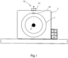
- eine schematische Darstellung einer rotierenden Maschine mit einer erfindungsgemäßen Vorrichtung und
- Fig. 2
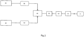
- eine schematische Darstellung des Erfindungsgemäßen Verfahrens mit Hilfe eines Blockschaltbilds.
- Fig. 1
- a schematic representation of a rotating machine with a device according to the invention and
- Fig. 2
- a schematic representation of the inventive method using a block diagram.
Im Folgenden wird die Erfindung mit Bezug auf die
In
In den Beschleunigungssignalen Sb sind diejenigen für eine Unwucht signifikanten Beschleunigungskomponenten enthalten, die sich mit der Drehzahl der rotierenden Maschine periodisch wiederholen.The acceleration signals Sb contain those acceleration components that are significant for an unbalance and that repeat periodically with the rotational speed of the rotating machine.
Ferner ist ein zweiter Sensor (30), nämlich ein Hall-Sensor zur gleichzeitigen Ermittlung von Signalen Sd zur Drehzahlbestimmung der rotierenden Maschine vorgesehen und am Stator montiert.Furthermore, a second sensor (30), namely a Hall sensor for the simultaneous detection of signals Sd for speed determination of the rotating machine is provided and mounted on the stator.
Darüber hinaus ist die Vorrichtung mit einem Mikrocontroller 40 ausgebildet, der wie in dem Blockschaltbild der
Somit ist gemäß dieser Ausführungsform möglich eine Auswertung der Beschleunigung vorzunehmen, die sich auf die Anregung 1. Ordnung (umlaufende radiale Kraftkomponente bedingt durch Drehung des Rotationskörpers) beschränkt, wodurch sich der Rechenaufwand des Mikrocontrollers entsprechend reduziert. Ferner werden Störeinflüsse durch Fremdanregung ausgeblendet und beim Überschreiten eines vorgegebenen Schwellenwertes mit radialer Beschleunigungskomponente wird eine Unwucht detektiert.Thus, according to this embodiment, it is possible to carry out an evaluation of the acceleration which is limited to the excitation of the first order (circumferential radial force component due to rotation of the rotational body), as a result of which the computing effort of the microcontroller is correspondingly reduced. Furthermore, interference caused by external excitation are hidden and when exceeding a predetermined threshold with radial acceleration component an imbalance is detected.
Wie in dem Ausführungsbeispiel in den
Somit kann, wie im Blockschaltbild der
- Ermittlung von Beschleunigungssignalen Sb
mit dem Beschleunigungssensor 20am Gehäuses 2; - Ermittlung von Signalen Sd mittels des Hall-
Sensors 30 zur Drehzahlbestimmung der rotierenden Maschine 1; - Zuführen und Auswerten der Sensorsignale Sb, Sd mittels einer Auswerteeinheit aus Mikrocontroller 40,
Signalaufbereitungseinheit 50 und eine Signalverarbeitungseinheit 60, wobei eine sich mit der Drehzahl der rotierenden Maschine 1 radiale (insbesondere periodisch auftretende) Beschleunigungskomponente erfasst wird und diese Komponente mit einem vorbestimmten Grenzwert vergleichen wird.
- Determination of acceleration signals Sb with the
acceleration sensor 20 on thehousing 2; - Determining signals Sd by means of the
Hall sensor 30 for speed determination of the rotating machine 1; - Supplying and evaluating the sensor signals Sb, Sd by means of an evaluation unit of
microcontroller 40,signal conditioning unit 50 and asignal processing unit 60, wherein a with the rotational speed of the rotating machine 1 radial (in particular periodically occurring) acceleration component is detected and this component is compared with a predetermined limit ,
Beim letzten Schritt werden zur Beurteilung der Unwucht der geglättete Mittelwert der orthogonalen Komponenten und/oder Amplituden des Beschleunigungssignals Sb ermittelt, wobei vor der Ermittlung der orthogonalen Komponenten und/oder Amplituden des Beschleunigungssignals Sb das Signal durch eine Signalaufbereitung- und/oder Signalverarbeitung 50, 60 bandpassgefiltert wurde.In the last step, the smoothed average of the orthogonal components and / or amplitudes of the acceleration signal Sb are determined to assess the imbalance, wherein before the determination of the orthogonal components and / or amplitudes of the acceleration signal Sb, the signal by a signal conditioning and / or
Claims (12)
Applications Claiming Priority (1)
| Application Number | Priority Date | Filing Date | Title |
|---|---|---|---|
| DE102017108109.7A DE102017108109A1 (en) | 2017-04-13 | 2017-04-13 | Method and device for unbalance detection |
Publications (2)
| Publication Number | Publication Date |
|---|---|
| EP3388810A1 true EP3388810A1 (en) | 2018-10-17 |
| EP3388810B1 EP3388810B1 (en) | 2020-03-11 |
Family
ID=61408449
Family Applications (1)
| Application Number | Title | Priority Date | Filing Date |
|---|---|---|---|
| EP18165982.2A Active EP3388810B1 (en) | 2017-04-13 | 2018-04-05 | Method and device for unbalance detection |
Country Status (4)
| Country | Link |
|---|---|
| US (1) | US11585718B2 (en) |
| EP (1) | EP3388810B1 (en) |
| CN (1) | CN206974613U (en) |
| DE (1) | DE102017108109A1 (en) |
Citations (3)
| Publication number | Priority date | Publication date | Assignee | Title |
|---|---|---|---|---|
| EP0770860A2 (en) * | 1995-10-25 | 1997-05-02 | Heraeus Instruments GmbH | Method and device for determination of unbalance and application of the device |
| DE102014116527A1 (en) * | 2014-11-12 | 2016-05-12 | Andreas Hettich Gmbh & Co. Kg | Centrifuge and method for detecting imbalances in the centrifuge |
| DE102015102476A1 (en) * | 2015-02-20 | 2016-08-25 | Hanning Elektro-Werke Gmbh & Co. Kg | drive arrangement |
Family Cites Families (8)
| Publication number | Priority date | Publication date | Assignee | Title |
|---|---|---|---|---|
| DE3937403A1 (en) * | 1989-11-10 | 1991-05-16 | Porsche Ag | Monitoring functionality of motor vehicle chassis during travel - using microcomputer to process vibration detector signals to monitor wheel imbalance and shock absorber state |
| EP0455878A3 (en) | 1990-05-05 | 1992-01-22 | Heraeus Sepatech Gmbh | Laboratory centrifuge |
| US6353384B1 (en) * | 1999-08-09 | 2002-03-05 | Meritor Heavy Vehicle Systems, Llc | Wheel rotation sensor and accelerometer to determine out of balance condition |
| US20090139327A1 (en) * | 2005-09-06 | 2009-06-04 | Volvo Lastvagnar Ab | Method and a system for determining wheel imbalances of at least one wheel on a vehicle |
| KR100905937B1 (en) | 2007-05-03 | 2009-07-06 | 국방과학연구소 | Brushless dc motor using linear hall-effect sensor and realization method of speed signal thereof |
| DE102013205353B4 (en) * | 2013-03-26 | 2020-06-18 | Hauni Maschinenbau Gmbh | Process for maintaining a machine in the tobacco processing industry, and machine set up accordingly |
| US20150284895A1 (en) * | 2014-04-07 | 2015-10-08 | General Electric Company | Impulse used to detect periodic speed variation caused by unbalanced loads in washing machine |
| US9574965B2 (en) * | 2014-06-24 | 2017-02-21 | General Electric Company | System and method of determining bearing health in a rotating machine |
-
2017
- 2017-04-13 DE DE102017108109.7A patent/DE102017108109A1/en active Pending
- 2017-06-15 CN CN201720697422.8U patent/CN206974613U/en active Active
-
2018
- 2018-04-05 EP EP18165982.2A patent/EP3388810B1/en active Active
- 2018-04-12 US US15/951,264 patent/US11585718B2/en active Active
Patent Citations (3)
| Publication number | Priority date | Publication date | Assignee | Title |
|---|---|---|---|---|
| EP0770860A2 (en) * | 1995-10-25 | 1997-05-02 | Heraeus Instruments GmbH | Method and device for determination of unbalance and application of the device |
| DE102014116527A1 (en) * | 2014-11-12 | 2016-05-12 | Andreas Hettich Gmbh & Co. Kg | Centrifuge and method for detecting imbalances in the centrifuge |
| DE102015102476A1 (en) * | 2015-02-20 | 2016-08-25 | Hanning Elektro-Werke Gmbh & Co. Kg | drive arrangement |
Also Published As
| Publication number | Publication date |
|---|---|
| US11585718B2 (en) | 2023-02-21 |
| CN206974613U (en) | 2018-02-06 |
| DE102017108109A1 (en) | 2018-10-18 |
| EP3388810B1 (en) | 2020-03-11 |
| US20180299341A1 (en) | 2018-10-18 |
Similar Documents
| Publication | Publication Date | Title |
|---|---|---|
| EP2083338B1 (en) | Process and device for monitoring a machine | |
| EP2131178B1 (en) | Diagnostic method for at least one ball bearing, in particular for an angular ball bearing, a corresponding diagnostic system and the use of such a diagnostic system | |
| DE102008025596B4 (en) | Procedure for operating a facility | |
| EP2549257B1 (en) | Method for detecting damage to drives | |
| DE102016216304A1 (en) | Bearing diagnostic device for a machine tool | |
| EP1423827A2 (en) | Device and method for the early recognition and prediction of unit damage | |
| DE102009038011B9 (en) | Method for automatic detection and detection of errors on a balancing machine | |
| WO2017102375A1 (en) | Method for monitoring the status of an electronic power steering device or of at least one component of the electronic power steering device of a motor vehicle. | |
| WO2015036021A1 (en) | Method and arrangement for monitoring an industrial device such as, for example, a machine or a system | |
| DE112012002234B4 (en) | Motor control device | |
| WO2015043619A1 (en) | Method and device for monitoring the state of a drive system comprising an electrical drive unit | |
| WO2012140140A1 (en) | Device for monitoring an apparatus, which vibrates during operation, of a domestic appliance and domestic appliance for the care of laundry items | |
| DE202019101262U1 (en) | Apparatus for continuous vibration monitoring | |
| EP2098929B1 (en) | Method of operating a machine powered by an electric drive with status recognition by means of frequency analysis | |
| DE102015118560A1 (en) | ENGINE CONTROL DEVICE DETECTING OVERLOAD | |
| EP3388810B1 (en) | Method and device for unbalance detection | |
| DE202017102270U1 (en) | Device for unbalance detection | |
| EP3706308A1 (en) | Continuous vibration monitoring device | |
| EP3225967B1 (en) | A device for error diagnosis of low-speed bearings | |
| WO2023020698A1 (en) | Method and device for monitoring an electric machine | |
| DE102019207545B3 (en) | Method for determining a fault in an electrical machine and electrical machine | |
| DE102015205412B4 (en) | Method and device for monitoring a bearing of a multi-phase electrical machine | |
| WO2021241468A1 (en) | Diagnosis device, diagnosis method, and diagnosis program | |
| AT516959B1 (en) | Method and device for condition monitoring of machines | |
| DE102019201985B4 (en) | Method for detecting a fault in an electrical machine for a vehicle |
Legal Events
| Date | Code | Title | Description |
|---|---|---|---|
| PUAI | Public reference made under article 153(3) epc to a published international application that has entered the european phase |
Free format text: ORIGINAL CODE: 0009012 |
|
| STAA | Information on the status of an ep patent application or granted ep patent |
Free format text: STATUS: THE APPLICATION HAS BEEN PUBLISHED |
|
| AK | Designated contracting states |
Kind code of ref document: A1 Designated state(s): AL AT BE BG CH CY CZ DE DK EE ES FI FR GB GR HR HU IE IS IT LI LT LU LV MC MK MT NL NO PL PT RO RS SE SI SK SM TR |
|
| AX | Request for extension of the european patent |
Extension state: BA ME |
|
| STAA | Information on the status of an ep patent application or granted ep patent |
Free format text: STATUS: REQUEST FOR EXAMINATION WAS MADE |
|
| 17P | Request for examination filed |
Effective date: 20190315 |
|
| RBV | Designated contracting states (corrected) |
Designated state(s): AL AT BE BG CH CY CZ DE DK EE ES FI FR GB GR HR HU IE IS IT LI LT LU LV MC MK MT NL NO PL PT RO RS SE SI SK SM TR |
|
| GRAP | Despatch of communication of intention to grant a patent |
Free format text: ORIGINAL CODE: EPIDOSNIGR1 |
|
| STAA | Information on the status of an ep patent application or granted ep patent |
Free format text: STATUS: GRANT OF PATENT IS INTENDED |
|
| RIC1 | Information provided on ipc code assigned before grant |
Ipc: G01M 1/28 20060101ALI20190902BHEP Ipc: G01P 15/097 20060101ALI20190902BHEP Ipc: G01M 1/22 20060101AFI20190902BHEP |
|
| INTG | Intention to grant announced |
Effective date: 20191008 |
|
| GRAS | Grant fee paid |
Free format text: ORIGINAL CODE: EPIDOSNIGR3 |
|
| GRAA | (expected) grant |
Free format text: ORIGINAL CODE: 0009210 |
|
| STAA | Information on the status of an ep patent application or granted ep patent |
Free format text: STATUS: THE PATENT HAS BEEN GRANTED |
|
| AK | Designated contracting states |
Kind code of ref document: B1 Designated state(s): AL AT BE BG CH CY CZ DE DK EE ES FI FR GB GR HR HU IE IS IT LI LT LU LV MC MK MT NL NO PL PT RO RS SE SI SK SM TR |
|
| REG | Reference to a national code |
Ref country code: GB Ref legal event code: FG4D Free format text: NOT ENGLISH |
|
| REG | Reference to a national code |
Ref country code: CH Ref legal event code: EP |
|
| REG | Reference to a national code |
Ref country code: AT Ref legal event code: REF Ref document number: 1243735 Country of ref document: AT Kind code of ref document: T Effective date: 20200315 |
|
| REG | Reference to a national code |
Ref country code: DE Ref legal event code: R096 Ref document number: 502018000912 Country of ref document: DE |
|
| REG | Reference to a national code |
Ref country code: IE Ref legal event code: FG4D Free format text: LANGUAGE OF EP DOCUMENT: GERMAN |
|
| REG | Reference to a national code |
Ref country code: SE Ref legal event code: TRGR |
|
| REG | Reference to a national code |
Ref country code: NL Ref legal event code: FP |
|
| PG25 | Lapsed in a contracting state [announced via postgrant information from national office to epo] |
Ref country code: RS Free format text: LAPSE BECAUSE OF FAILURE TO SUBMIT A TRANSLATION OF THE DESCRIPTION OR TO PAY THE FEE WITHIN THE PRESCRIBED TIME-LIMIT Effective date: 20200311 Ref country code: NO Free format text: LAPSE BECAUSE OF FAILURE TO SUBMIT A TRANSLATION OF THE DESCRIPTION OR TO PAY THE FEE WITHIN THE PRESCRIBED TIME-LIMIT Effective date: 20200611 Ref country code: FI Free format text: LAPSE BECAUSE OF FAILURE TO SUBMIT A TRANSLATION OF THE DESCRIPTION OR TO PAY THE FEE WITHIN THE PRESCRIBED TIME-LIMIT Effective date: 20200311 |
|
| PG25 | Lapsed in a contracting state [announced via postgrant information from national office to epo] |
Ref country code: LV Free format text: LAPSE BECAUSE OF FAILURE TO SUBMIT A TRANSLATION OF THE DESCRIPTION OR TO PAY THE FEE WITHIN THE PRESCRIBED TIME-LIMIT Effective date: 20200311 Ref country code: GR Free format text: LAPSE BECAUSE OF FAILURE TO SUBMIT A TRANSLATION OF THE DESCRIPTION OR TO PAY THE FEE WITHIN THE PRESCRIBED TIME-LIMIT Effective date: 20200612 Ref country code: BG Free format text: LAPSE BECAUSE OF FAILURE TO SUBMIT A TRANSLATION OF THE DESCRIPTION OR TO PAY THE FEE WITHIN THE PRESCRIBED TIME-LIMIT Effective date: 20200611 Ref country code: HR Free format text: LAPSE BECAUSE OF FAILURE TO SUBMIT A TRANSLATION OF THE DESCRIPTION OR TO PAY THE FEE WITHIN THE PRESCRIBED TIME-LIMIT Effective date: 20200311 |
|
| REG | Reference to a national code |
Ref country code: LT Ref legal event code: MG4D |
|
| PG25 | Lapsed in a contracting state [announced via postgrant information from national office to epo] |
Ref country code: LT Free format text: LAPSE BECAUSE OF FAILURE TO SUBMIT A TRANSLATION OF THE DESCRIPTION OR TO PAY THE FEE WITHIN THE PRESCRIBED TIME-LIMIT Effective date: 20200311 Ref country code: EE Free format text: LAPSE BECAUSE OF FAILURE TO SUBMIT A TRANSLATION OF THE DESCRIPTION OR TO PAY THE FEE WITHIN THE PRESCRIBED TIME-LIMIT Effective date: 20200311 Ref country code: SK Free format text: LAPSE BECAUSE OF FAILURE TO SUBMIT A TRANSLATION OF THE DESCRIPTION OR TO PAY THE FEE WITHIN THE PRESCRIBED TIME-LIMIT Effective date: 20200311 Ref country code: PT Free format text: LAPSE BECAUSE OF FAILURE TO SUBMIT A TRANSLATION OF THE DESCRIPTION OR TO PAY THE FEE WITHIN THE PRESCRIBED TIME-LIMIT Effective date: 20200805 Ref country code: IS Free format text: LAPSE BECAUSE OF FAILURE TO SUBMIT A TRANSLATION OF THE DESCRIPTION OR TO PAY THE FEE WITHIN THE PRESCRIBED TIME-LIMIT Effective date: 20200711 Ref country code: RO Free format text: LAPSE BECAUSE OF FAILURE TO SUBMIT A TRANSLATION OF THE DESCRIPTION OR TO PAY THE FEE WITHIN THE PRESCRIBED TIME-LIMIT Effective date: 20200311 Ref country code: SM Free format text: LAPSE BECAUSE OF FAILURE TO SUBMIT A TRANSLATION OF THE DESCRIPTION OR TO PAY THE FEE WITHIN THE PRESCRIBED TIME-LIMIT Effective date: 20200311 |
|
| REG | Reference to a national code |
Ref country code: DE Ref legal event code: R026 Ref document number: 502018000912 Country of ref document: DE |
|
| PLBI | Opposition filed |
Free format text: ORIGINAL CODE: 0009260 |
|
| PG25 | Lapsed in a contracting state [announced via postgrant information from national office to epo] |
Ref country code: MC Free format text: LAPSE BECAUSE OF FAILURE TO SUBMIT A TRANSLATION OF THE DESCRIPTION OR TO PAY THE FEE WITHIN THE PRESCRIBED TIME-LIMIT Effective date: 20200311 |
|
| PLAX | Notice of opposition and request to file observation + time limit sent |
Free format text: ORIGINAL CODE: EPIDOSNOBS2 |
|
| 26 | Opposition filed |
Opponent name: ZIEHL-ABEGG SE Effective date: 20201210 |
|
| PG25 | Lapsed in a contracting state [announced via postgrant information from national office to epo] |
Ref country code: LU Free format text: LAPSE BECAUSE OF NON-PAYMENT OF DUE FEES Effective date: 20200405 Ref country code: ES Free format text: LAPSE BECAUSE OF FAILURE TO SUBMIT A TRANSLATION OF THE DESCRIPTION OR TO PAY THE FEE WITHIN THE PRESCRIBED TIME-LIMIT Effective date: 20200311 Ref country code: DK Free format text: LAPSE BECAUSE OF FAILURE TO SUBMIT A TRANSLATION OF THE DESCRIPTION OR TO PAY THE FEE WITHIN THE PRESCRIBED TIME-LIMIT Effective date: 20200311 |
|
| REG | Reference to a national code |
Ref country code: BE Ref legal event code: MM Effective date: 20200430 |
|
| PG25 | Lapsed in a contracting state [announced via postgrant information from national office to epo] |
Ref country code: BE Free format text: LAPSE BECAUSE OF NON-PAYMENT OF DUE FEES Effective date: 20200430 Ref country code: SI Free format text: LAPSE BECAUSE OF FAILURE TO SUBMIT A TRANSLATION OF THE DESCRIPTION OR TO PAY THE FEE WITHIN THE PRESCRIBED TIME-LIMIT Effective date: 20200311 Ref country code: PL Free format text: LAPSE BECAUSE OF FAILURE TO SUBMIT A TRANSLATION OF THE DESCRIPTION OR TO PAY THE FEE WITHIN THE PRESCRIBED TIME-LIMIT Effective date: 20200311 |
|
| PG25 | Lapsed in a contracting state [announced via postgrant information from national office to epo] |
Ref country code: IE Free format text: LAPSE BECAUSE OF NON-PAYMENT OF DUE FEES Effective date: 20200405 |
|
| PLBB | Reply of patent proprietor to notice(s) of opposition received |
Free format text: ORIGINAL CODE: EPIDOSNOBS3 |
|
| RDAF | Communication despatched that patent is revoked |
Free format text: ORIGINAL CODE: EPIDOSNREV1 |
|
| PG25 | Lapsed in a contracting state [announced via postgrant information from national office to epo] |
Ref country code: CH Free format text: LAPSE BECAUSE OF NON-PAYMENT OF DUE FEES Effective date: 20210430 Ref country code: LI Free format text: LAPSE BECAUSE OF NON-PAYMENT OF DUE FEES Effective date: 20210430 |
|
| APBM | Appeal reference recorded |
Free format text: ORIGINAL CODE: EPIDOSNREFNO |
|
| APBP | Date of receipt of notice of appeal recorded |
Free format text: ORIGINAL CODE: EPIDOSNNOA2O |
|
| APAH | Appeal reference modified |
Free format text: ORIGINAL CODE: EPIDOSCREFNO |
|
| APBQ | Date of receipt of statement of grounds of appeal recorded |
Free format text: ORIGINAL CODE: EPIDOSNNOA3O |
|
| PG25 | Lapsed in a contracting state [announced via postgrant information from national office to epo] |
Ref country code: TR Free format text: LAPSE BECAUSE OF FAILURE TO SUBMIT A TRANSLATION OF THE DESCRIPTION OR TO PAY THE FEE WITHIN THE PRESCRIBED TIME-LIMIT Effective date: 20200311 Ref country code: MT Free format text: LAPSE BECAUSE OF FAILURE TO SUBMIT A TRANSLATION OF THE DESCRIPTION OR TO PAY THE FEE WITHIN THE PRESCRIBED TIME-LIMIT Effective date: 20200311 Ref country code: CY Free format text: LAPSE BECAUSE OF FAILURE TO SUBMIT A TRANSLATION OF THE DESCRIPTION OR TO PAY THE FEE WITHIN THE PRESCRIBED TIME-LIMIT Effective date: 20200311 |
|
| PG25 | Lapsed in a contracting state [announced via postgrant information from national office to epo] |
Ref country code: MK Free format text: LAPSE BECAUSE OF FAILURE TO SUBMIT A TRANSLATION OF THE DESCRIPTION OR TO PAY THE FEE WITHIN THE PRESCRIBED TIME-LIMIT Effective date: 20200311 Ref country code: AL Free format text: LAPSE BECAUSE OF FAILURE TO SUBMIT A TRANSLATION OF THE DESCRIPTION OR TO PAY THE FEE WITHIN THE PRESCRIBED TIME-LIMIT Effective date: 20200311 |
|
| PGFP | Annual fee paid to national office [announced via postgrant information from national office to epo] |
Ref country code: CZ Payment date: 20230327 Year of fee payment: 6 |
|
| P01 | Opt-out of the competence of the unified patent court (upc) registered |
Effective date: 20230522 |
|
| PGFP | Annual fee paid to national office [announced via postgrant information from national office to epo] |
Ref country code: NL Payment date: 20230417 Year of fee payment: 6 |
|
| PGFP | Annual fee paid to national office [announced via postgrant information from national office to epo] |
Ref country code: IT Payment date: 20230428 Year of fee payment: 6 Ref country code: FR Payment date: 20230417 Year of fee payment: 6 Ref country code: DE Payment date: 20230418 Year of fee payment: 6 |
|
| PGFP | Annual fee paid to national office [announced via postgrant information from national office to epo] |
Ref country code: SE Payment date: 20230419 Year of fee payment: 6 Ref country code: AT Payment date: 20230414 Year of fee payment: 6 |
|
| PGFP | Annual fee paid to national office [announced via postgrant information from national office to epo] |
Ref country code: GB Payment date: 20230420 Year of fee payment: 6 |
|
| PGFP | Annual fee paid to national office [announced via postgrant information from national office to epo] |
Ref country code: CZ Payment date: 20240327 Year of fee payment: 7 |