EP3388720A1 - Structure for preventing grease leakage in gear reducer - Google Patents
Structure for preventing grease leakage in gear reducer Download PDFInfo
- Publication number
- EP3388720A1 EP3388720A1 EP18174191.9A EP18174191A EP3388720A1 EP 3388720 A1 EP3388720 A1 EP 3388720A1 EP 18174191 A EP18174191 A EP 18174191A EP 3388720 A1 EP3388720 A1 EP 3388720A1
- Authority
- EP
- European Patent Office
- Prior art keywords
- grease
- dynamoelectric machine
- output shaft
- gear reducer
- gear
- Prior art date
- Legal status (The legal status is an assumption and is not a legal conclusion. Google has not performed a legal analysis and makes no representation as to the accuracy of the status listed.)
- Granted
Links
Images


Classifications
-
- F—MECHANICAL ENGINEERING; LIGHTING; HEATING; WEAPONS; BLASTING
- F16—ENGINEERING ELEMENTS AND UNITS; GENERAL MEASURES FOR PRODUCING AND MAINTAINING EFFECTIVE FUNCTIONING OF MACHINES OR INSTALLATIONS; THERMAL INSULATION IN GENERAL
- F16J—PISTONS; CYLINDERS; SEALINGS
- F16J15/00—Sealings
- F16J15/16—Sealings between relatively-moving surfaces
- F16J15/40—Sealings between relatively-moving surfaces by means of fluid
-
- F—MECHANICAL ENGINEERING; LIGHTING; HEATING; WEAPONS; BLASTING
- F16—ENGINEERING ELEMENTS AND UNITS; GENERAL MEASURES FOR PRODUCING AND MAINTAINING EFFECTIVE FUNCTIONING OF MACHINES OR INSTALLATIONS; THERMAL INSULATION IN GENERAL
- F16H—GEARING
- F16H57/00—General details of gearing
- F16H57/02—Gearboxes; Mounting gearing therein
- F16H57/029—Gearboxes; Mounting gearing therein characterised by means for sealing the gearboxes, e.g. to improve airtightness
-
- F—MECHANICAL ENGINEERING; LIGHTING; HEATING; WEAPONS; BLASTING
- F16—ENGINEERING ELEMENTS AND UNITS; GENERAL MEASURES FOR PRODUCING AND MAINTAINING EFFECTIVE FUNCTIONING OF MACHINES OR INSTALLATIONS; THERMAL INSULATION IN GENERAL
- F16H—GEARING
- F16H57/00—General details of gearing
- F16H57/04—Features relating to lubrication or cooling or heating
- F16H57/0463—Grease lubrication; Drop-feed lubrication
- F16H57/0464—Grease lubrication
-
- F—MECHANICAL ENGINEERING; LIGHTING; HEATING; WEAPONS; BLASTING
- F16—ENGINEERING ELEMENTS AND UNITS; GENERAL MEASURES FOR PRODUCING AND MAINTAINING EFFECTIVE FUNCTIONING OF MACHINES OR INSTALLATIONS; THERMAL INSULATION IN GENERAL
- F16H—GEARING
- F16H57/00—General details of gearing
- F16H57/04—Features relating to lubrication or cooling or heating
- F16H57/048—Type of gearings to be lubricated, cooled or heated
- F16H57/0493—Gearings with spur or bevel gears
- F16H57/0495—Gearings with spur or bevel gears with fixed gear ratio
-
- F—MECHANICAL ENGINEERING; LIGHTING; HEATING; WEAPONS; BLASTING
- F16—ENGINEERING ELEMENTS AND UNITS; GENERAL MEASURES FOR PRODUCING AND MAINTAINING EFFECTIVE FUNCTIONING OF MACHINES OR INSTALLATIONS; THERMAL INSULATION IN GENERAL
- F16J—PISTONS; CYLINDERS; SEALINGS
- F16J15/00—Sealings
- F16J15/16—Sealings between relatively-moving surfaces
- F16J15/40—Sealings between relatively-moving surfaces by means of fluid
- F16J15/406—Sealings between relatively-moving surfaces by means of fluid by at least one pump
-
- F—MECHANICAL ENGINEERING; LIGHTING; HEATING; WEAPONS; BLASTING
- F16—ENGINEERING ELEMENTS AND UNITS; GENERAL MEASURES FOR PRODUCING AND MAINTAINING EFFECTIVE FUNCTIONING OF MACHINES OR INSTALLATIONS; THERMAL INSULATION IN GENERAL
- F16J—PISTONS; CYLINDERS; SEALINGS
- F16J15/00—Sealings
- F16J15/44—Free-space packings
-
- H—ELECTRICITY
- H02—GENERATION; CONVERSION OR DISTRIBUTION OF ELECTRIC POWER
- H02K—DYNAMO-ELECTRIC MACHINES
- H02K7/00—Arrangements for handling mechanical energy structurally associated with dynamo-electric machines, e.g. structural association with mechanical driving motors or auxiliary dynamo-electric machines
- H02K7/10—Structural association with clutches, brakes, gears, pulleys or mechanical starters
- H02K7/116—Structural association with clutches, brakes, gears, pulleys or mechanical starters with gears
-
- H—ELECTRICITY
- H02—GENERATION; CONVERSION OR DISTRIBUTION OF ELECTRIC POWER
- H02K—DYNAMO-ELECTRIC MACHINES
- H02K5/00—Casings; Enclosures; Supports
- H02K5/04—Casings or enclosures characterised by the shape, form or construction thereof
- H02K5/10—Casings or enclosures characterised by the shape, form or construction thereof with arrangements for protection from ingress, e.g. water or fingers
Definitions
- the present invention relates to a grease leakage preventing structure for a gear reducer in a dynamoelectric machine with a gear reducer.
- FIG. 8 illustrates an electric motor with a gear reducer that is one type of dynamoelectric machine with a gear reducer, in which a gear case 104 of a gear reducer 103 is engaged with and integrally assembled with, with bolts, not shown in the drawing, a bracket 102 on a protruding edge thereof, the bracket 102 being press-fitted into an opening end of an electric motor case 101 of an electric motor 100.
- oil seals 109 are arranged on a base end of a gear tooth portion 106a of an electric motor output shaft 106, which protrudes into an inside of the gear case 104 via an open hole 105a formed on a side panel 105 of the gear reducer 103.
- the oil seal 109 is arranged on the base end of the gear tooth portion 106a of the electric motor output shaft 106 together with the bearing 107 arranged on the bracket 102 of the electric motor case 101.
- the helical gear 108 is engaged with the electric motor output shaft 106 in the inside of the gear case 104.
- the efficiency of prevention of grease leakage may be improved by using oil seals 109B including more lip portions 109b with a structure such as a triple lip structure illustrated in FIG. 13(b) as the oil seals 109; however, in this case, the problems may become more difficult in terms of the friction load, the thickness, and the costs compared with the case of using the oil seals 109A including the single lip structure.
- the thickness of the oil seal 109 becomes greater than the thickness of the stator of the electric motor, which may thus impair the merits of the thin type electric motors, and in addition, the ratio of decrease in the output torque may become even higher due to the friction load from the oil seals 109.
- the purpose of the present invention is to provide a grease leakage preventing structure for a gear reducer of a dynamoelectric machine with the gear reducer capable of solving the above-described problems and preventing, if soft grease with high consistency is employed in a gear reducer driven at a high speed for high output power, leakage of grease from the reducer toward the dynamoelectric machine by covering an output shaft of the dynamoelectric machine with a grease blocking member.
- the present invention is a grease leakage preventing structure for a gear reducer of a dynamoelectric machine with the gear reducer, in which gear teeth are provided in a leading edge portion of an output shaft of the dynamoelectric machine, the leading edge portion of the dynamoelectric machine output shaft is introduced into a case of a gear reducer via an input port of the gear reducer, and the dynamoelectric machine output shaft with the gear teeth is engaged with a gear arranged inside the case of the gear reducer, and the grease leakage preventing structure includes a grease blocking member provided on a terminal end of an engagement portion of the dynamoelectric machine output shaft and configured to inhibit inflow of grease into the dynamoelectric machine, and in this structure, the grease blocking member is provided with a wall surface portion formed in a direction perpendicular to the gear teeth provided in the leading edge portion of the dynamoelectric machine output shaft.
- a plurality of protrusions is provided on a surface of a cylindrical portion of the grease blocking member formed in a direction perpendicular to the gear teeth provided in the leading edge portion of the dynamoelectric machine output shaft as the wall surface portion of the grease blocking member.
- V-shaped or U-shaped protrusions are provided in the cylindrical portion of the grease blocking member at two or more locations along an axial direction as the wall surface portion of the grease blocking member.
- V-shaped or U-shaped cutout portions are provided in the cylindrical portion of the grease blocking member formed in a peripheral portion of a leading edge of the cylindrical portion at at least one location along an axial direction as the wall surface portion of the grease blocking member.
- the grease blocking member is provided with a flange portion provided on a base end thereof.
- the grease blocking member is provided with a tapered portion provided between the cylindrical portion and the flange portion and having a diameter gradually expanding from the cylindrical portion.
- the grease blocking member is made of aluminium and is mounted by press-fitting to the dynamoelectric machine output shaft.
- helically cut gear teeth are provided as the gear teeth provided as the gear teeth provided in the leading edge portion of the dynamoelectric machine output shaft.
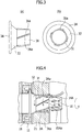
- FIG. 1 illustrates an electric motor with a gear reducer that is one type of dynamoelectric machine with a gear reducer according to the present invention, in which an inside of the gear reducer is not shown.
- FIG. 2 illustrates a grease blocking member mounted on an electric motor output shaft.
- FIGs. 3(a) and 3(b) are magnified views of the grease blocking member.
- the electric motor includes an electric motor main body 1, a gear reducer main body 2 that is assembled with the electric motor main body 1, and an electric motor case 10 constituting the electric motor main body 1, and a bracket 11 is provided, which is press-fitted on one opening end of the electric motor case 10.
- a gear case 20 of the gear reducer main body 2 is fitted with the bracket 11 on its protruding end, and the electric motor case 10 and the gear case 20 are integrally fastened with bolts, not shown in the drawings.
- a rotator 13 is concentrically arranged on an axis of a stator 12, and the rotator 13 is rotatably supported on both ends of a rotational shaft 14 via bearings 15 1 , 15 2 .
- one end of the rotational shaft 14 is delivered outward from an open hole 11a of the bracket 11, and thereby an electric motor output shaft 14A is constituted.
- the electric motor output shaft 14A is provided with helically cut gear teeth 16, and a portion 17 with the helically cut gear teeth 16 is inserted into the gear case 20 of the gear reducer main body 2 through a hole 21a of a gear reducer flange 21 to be engaged with a helical gear 22 arranged inside the gear case 20.
- An oil seal 18 is a single lip oil seal arranged on an inner periphery surface of the open hole 11a of the bracket 11.
- a grease blocking member 3A is a member for preventing leakage of grease, which is mounted by press-fitting onto the electric motor output shaft 14A at a location closer to the base end of the shaft than the portion 17 with the helically cut gear teeth 16.
- the grease blocking member 3A is constituted by a cylindrical portion 31 and an expansion portion 32, which is provided so as to form a shape of a horn in which the diameter gradually increases from one end of the cylindrical portion 31.
- a plurality of linear protrusions 31a is provided at a reverse angle from the helically cut gear teeth 16 in a leading edge portion of the electric motor output shaft 14A.
- a wall surface portion 3Aa of the protrusions 31a is formed in a direction perpendicular to the helically cut gear teeth 16 so as to block the grease flowing in and coming along the surface of the helically cut gear teeth 16 provided in the leading edge portion of the electric motor output shaft 14A.
- the grease blocking member 3A is produced by die casting of aluminium or resin molding of silicon performed so that a plurality of linear protrusions 31a is provided at a reverse angle from the helically cut gear teeth 16 provided in the leading edge portion of the electric motor output shaft 14A. In mounting the grease blocking member 3A, the grease blocking member 3A is assembled with the electric motor output shaft 14A by press-fitting except for a portion 16b for engagement with the helical gear 22 of the reducer.
- the grease blocking member 3A for preventing inflow of the grease into the electric motor is press-fitted to be engaged with the electric motor output shaft 14A on a terminal end of the shaft by detouring around the engagement portion 16b of the electric motor output shaft 14A, and the protrusions 31a of the grease blocking member 3A are arranged in the direction perpendicular to the helically cut gear teeth 16.
- the wall surface portion 3Aa for blocking inflow of the grease is provided on the front side of the protrusions 31a of the grease blocking member 3A.
- the grease blocking member 3A is provided with a plurality of linear protrusions 31a that are formed in the reverse angle from the helically cut gear teeth 16 provided in the leading edge portion of the electric motor output shaft 14A, an action for forcing back the grease flowing out to the side of the electric motor due to the helically cut gear teeth 16 of the electric motor output shaft 14A toward the gear reducer is caused by the wall surface portion 3Aa as the linear protrusions 31a provided at the reverse angle from the helically cut gear teeth turn. With this configuration, leakage of the grease flowing out from inside the reducer via the gear reducer flange 21 to the side of the electric motor can be prevented.
- FIGs. 5(a) and 5(b) illustrate another embodiment of the grease blocking member 3 of the present invention, in which the same portions and components as those illustrated in FIGs. 3 and 4 are provided with the same reference symbols and numerals.
- a grease blocking member 3B is provided with V-shaped or U-shaped protrusions 3 1b formed on the cylindrical portion 31 at two locations.
- the grease blocking member 3B is used, in which V-shaped or U-shaped protrusions 3 1b are provided in the cylindrical portion 31 at two or more locations, instead of the grease blocking member 3A.
- V-shaped protrusions 31b are formed on the grease blocking member 3B, even if the grease has leaked over to reach the grease blocking member 3B, the leaked grease can be forced back by a wall surface portion 3Ba of the protrusions 3 1b provided at the reverse angle from the helically cut gear teeth as the grease blocking member 3B turns.
- the protrusions 3 1b may be provided at more than two locations.
- FIGs. 6(a) and 6(b) also illustrate another embodiment of the grease blocking member 3 of the present invention, in which the same portions and components as those illustrated in FIGs. 3 and 4 are provided with the same reference symbols and numerals.
- a grease blocking member 3C is provided with U-shaped cut portions 33 at two locations in the leading edge portion from the cylindrical portion 31 to the expansion portion 32.
- the grease blocking member 3C is used in which the cut portions 33 are provided at two or more locations that cut the leading edge portion of the grease blocking member 3C in the V-like or U-like shape.
- the cut portions 33 formed in the leading edge portion of the grease blocking member 3C infiltration of grease can be prevented by a wall surface portion 3Ca of the cut portions 33 provided at the reverse angle from the helically cut gear teeth, and similarly to the example that uses the grease blocking member 3B, grease accumulated in the cut portions 33 provided in the leading edge portion of the grease blocking member 3C can be forced back by the wall surface portion 3Ca toward the gear reducer as the grease blocking member 3C turns.
- the cut portions are provided at two locations; however, alternatively, the cut portion may provided at one location only (in this case, the cut portion is diagonally cut) or may be provided at more than two locations according to the diameter of the shaft of the electric motor output shaft.
- the grease blocking member 3C may be press-fitted to the electric motor output shaft 14A, and a labyrinth structure (flange portion) 34 which covers a lip portion of the oil seal 18 may be provided to the grease blocking member 3C at a location on the side of the electric motor. With this configuration, intrusion of grease into the electric motor can be absolutely blocked.
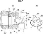
- FIGs. 7(a) and 7(b) illustrate a modification of the example illustrated in FIGs. 6(a) and 6(b) , in which the same portions and components as those in FIGs. 6(a) and 6(b) are provided with the same reference symbols and numerals and descriptions thereof are omitted below.
- a grease blocking member 3D is formed, in which the cut portions 33 formed in the leading edge portion of the cylindrical portion 31 in the axial direction are cut diagonally in relation to the axial direction, so that the sections thereof face outward to allow a wall surface 3Da formed by the sections to be viewed from a lateral direction.
- the present invention is not limited to the embodiments described above, and various shapes can be applied as the shape of the grease blocking member 3, 3A, 3B, 3C, 3D, for example, and the grease blocking member can take any shape such as the shape of the linear protrusions 31a, the V-shaped protrusions 31b, and the cut portions 33 if the grease blocking member is capable of inhibiting inflow of the grease, and the present invention can of course be appropriately modified or altered within a range that does not change the technical scope of the present invention.
- examples of the electric motors are described, and the present invention can be applied to a dynamoelectric machine provided with an output shaft that engages with a gear at an input port of the gear reducer.
- a dynamoelectric machine includes dynamos, generators, and the like, and also includes clutch brakes, electromagnetic brakes, torque limiters, intermediate reducers, and the like, which are arranged between the electric motor and the gear reducer and configured to transmit the rotation of the output shaft of the electric motor to the gear reducer.
Abstract
Description
- The present invention relates to a grease leakage preventing structure for a gear reducer in a dynamoelectric machine with a gear reducer.
-
FIG. 8 illustrates an electric motor with a gear reducer that is one type of dynamoelectric machine with a gear reducer, in which agear case 104 of agear reducer 103 is engaged with and integrally assembled with, with bolts, not shown in the drawing, abracket 102 on a protruding edge thereof, thebracket 102 being press-fitted into an opening end of anelectric motor case 101 of anelectric motor 100. - In such an electric motor with a gear reducer, in order to smoothly transmit rotation, a structure is employed in which helically cut gear teeth are provided on an output shaft of the electric motor to assemble the shaft with a helical gear of the reducer.
- However, a problem may arise in which grease adhered to the helical gear inside the reducer may flow out according to rotation of the gear via the tooth trace of the electric motor output shaft with the helically cut gear teeth and penetrate into the electric motor outside the case.
- As a conventional structure for preventing grease leakage in a gear reducer of the electric motor with a gear reducer of this type, a method has been known in which an oil seal is used to prevent the infiltration of grease into the inside of the electric motor.
- Referring to
FIG. 9 , in this method,oil seals 109 are arranged on a base end of agear tooth portion 106a of an electricmotor output shaft 106, which protrudes into an inside of thegear case 104 via anopen hole 105a formed on aside panel 105 of thegear reducer 103. Theoil seal 109 is arranged on the base end of thegear tooth portion 106a of the electricmotor output shaft 106 together with thebearing 107 arranged on thebracket 102 of theelectric motor case 101. Thehelical gear 108 is engaged with the electricmotor output shaft 106 in the inside of thegear case 104. - However, in the method using the
oil seals 109, because friction load is applied due to the contact between the oil seal and the electricmotor output shaft 106, the ratio of loss becomes great in a low-output electric motor. In addition, in providing theoil seals 109, it is necessary to detour around thegear tooth portion 106a of electricmotor output shaft 106, and it therefore becomes necessary to design the dimension of the oil seal so that it becomes long enough for detouring around the gear teeth. In particular, in thin-type electric motors, the thickness of the oil seal portion causes a problem. - In this regard, related art is known, as illustrated in
FIG. 10 , in which aflexible tube 110 is provided so as to cover thegear tooth portion 106a of the electricmotor output shaft 106, except for a portion of engagement with the helical gear 108 (see Patent Literature 1). - Furthermore, as illustrated in
FIG. 11 , related art has been known in which ahelical groove 201 is provided, which helically goes around an electricmotor output shaft 200 from the side of a bearing of the electric motor toward the side of the gear reducer (see Patent Literature 2). -
- Patent Literature 1:
JP 06-48210 Y - Patent Literature 2:
JP 2008-236903 A - In this regard, in such conventional structures for preventing grease leakage for gear reducers, if relatively hard grease with low consistency (NLGI Consistency No. 2) is employed in a gear reducer, grease leakage can be prevented by covering the electric
motor output shaft 106 withflexible tube 110 or by forminghelical groove 201 on the electricmotor output shaft 200. - However, problems may arise in cases of gear reducers driven at high rotation speeds for high output power, in which the grease may be splattered in the centrifugal direction of the gear due to the centrifugal force from the high-speed rotation of the gear, and thus, the grease would not enter into the gear in a sufficient amount, which may reduce the service life of the gear reducer. Thus, it is necessary to employ soft grease with high consistency (NLGI Consistency No. 0) for gear reducers driven at high speed for high output power. However, in the case of using grease which is softer and having a higher consistency compared with NLGI Consistency No. 0 grease, grease leakage cannot be prevented by covering the electric
motor output shaft 106 with theflexible tube 110 as illustrated inFIG. 10 or by forming thehelical groove 201 on the electricmotor output shaft 200 as illustrated inFIG. 11 . Furthermore, complex processes may be required and the processing costs may be high to form thehelical groove 201 on the shaft portion of the electricmotor output shaft 200. In particular, if the electric motor output shaft is provided with helically cut gear teeth, when the electric motor is rotated in a rotation direction illustrated inFIG. 12 , the grease in the gear reducer is drawn out toward the electric motor as indicated by solid arrows. Due to this pumping action, a large amount of grease may leak toward the electric motor as indicated by a dotted-line arrow inFIG. 12 . Therefore, grease leakage cannot be prevented by taking measures so that the electricmotor output shaft 106 is covered with theflexible tube 110 as illustrated inFIG. 9 and so thatoil seals 109A of asingle lip 109a are used as illustrated inFIG. 13(a) . - To address these problems, the efficiency of prevention of grease leakage may be improved by using
oil seals 109B includingmore lip portions 109b with a structure such as a triple lip structure illustrated inFIG. 13(b) as theoil seals 109; however, in this case, the problems may become more difficult in terms of the friction load, the thickness, and the costs compared with the case of using theoil seals 109A including the single lip structure. In particular, in the case of thin electric motors, the thickness of theoil seal 109 becomes greater than the thickness of the stator of the electric motor, which may thus impair the merits of the thin type electric motors, and in addition, the ratio of decrease in the output torque may become even higher due to the friction load from theoil seals 109. - The purpose of the present invention is to provide a grease leakage preventing structure for a gear reducer of a dynamoelectric machine with the gear reducer capable of solving the above-described problems and preventing, if soft grease with high consistency is employed in a gear reducer driven at a high speed for high output power, leakage of grease from the reducer toward the dynamoelectric machine by covering an output shaft of the dynamoelectric machine with a grease blocking member.
- In order to solve the above-described problems, according to an aspect of the present invention, the present invention is a grease leakage preventing structure for a gear reducer of a dynamoelectric machine with the gear reducer, in which gear teeth are provided in a leading edge portion of an output shaft of the dynamoelectric machine, the leading edge portion of the dynamoelectric machine output shaft is introduced into a case of a gear reducer via an input port of the gear reducer, and the dynamoelectric machine output shaft with the gear teeth is engaged with a gear arranged inside the case of the gear reducer, and the grease leakage preventing structure includes a grease blocking member provided on a terminal end of an engagement portion of the dynamoelectric machine output shaft and configured to inhibit inflow of grease into the dynamoelectric machine, and in this structure, the grease blocking member is provided with a wall surface portion formed in a direction perpendicular to the gear teeth provided in the leading edge portion of the dynamoelectric machine output shaft.
- In addition, according to an aspect of the present invention, a plurality of protrusions is provided on a surface of a cylindrical portion of the grease blocking member formed in a direction perpendicular to the gear teeth provided in the leading edge portion of the dynamoelectric machine output shaft as the wall surface portion of the grease blocking member.
- Furthermore, according to an aspect of the present invention, V-shaped or U-shaped protrusions are provided in the cylindrical portion of the grease blocking member at two or more locations along an axial direction as the wall surface portion of the grease blocking member.
- Furthermore, according to an aspect of the present invention, V-shaped or U-shaped cutout portions are provided in the cylindrical portion of the grease blocking member formed in a peripheral portion of a leading edge of the cylindrical portion at at least one location along an axial direction as the wall surface portion of the grease blocking member.
- In addition, according to an aspect of the present invention, the grease blocking member is provided with a flange portion provided on a base end thereof.
- Furthermore, according to an aspect of the present invention, the grease blocking member is provided with a tapered portion provided between the cylindrical portion and the flange portion and having a diameter gradually expanding from the cylindrical portion.
- Furthermore, according to an aspect of the present invention, the grease blocking member is made of aluminium and is mounted by press-fitting to the dynamoelectric machine output shaft.
- In addition, according to an aspect of the present invention, helically cut gear teeth are provided as the gear teeth provided as the gear teeth provided in the leading edge portion of the dynamoelectric machine output shaft.
- According to the present invention, if soft grease with high consistency is employed in a gear reducer driven at a high speed for high output power, leakage of grease from the reducer toward the dynamoelectric machine can be prevented by covering the output shaft of the dynamoelectric machine with the grease blocking member.
-
-
FIG. 1 is a cross section of a grease leakage preventing structure for a gear reducer of an electric motor with a gear reducer according to an embodiment of the present invention. -
FIG. 2 illustrates a grease blocking member of the present application for preventing inflow of grease assembled to an output shaft of the electric motor. -
FIG. 3 illustrates a grease blocking member for preventing inflow of grease, in whichFIG. 3(a) is a side view andFIG. 3(b) is a front view. -
FIG. 4 is an explanatory view illustrating prevention of grease leakage by the grease blocking member for preventing inflow of grease. -
FIG. 5 illustrates a grease leakage preventing structure for a gear reducer of an electric motor with a gear reducer according to another embodiment of the present invention, in whichFIG. 5(a) is a side view andFIG. 5(b) is a perspective view of the grease blocking member. -
FIG. 6 illustrates a grease leakage preventing structure for a gear reducer of an electric motor with a gear reducer according to another embodiment of the present invention, in whichFIG. 6(a) is a side view andFIG. 6(b) is a perspective view of the grease blocking member. -
FIG. 7 illustrates a modification of the grease blocking member illustrated inFIG. 6 , in whichFIG. 7(a) is a side view andFIG. 7(b) is a perspective view of the grease blocking member. -
FIG. 8 is a cross section of a structure of a conventional electric motor with a gear reducer. -
FIG. 9 illustrates a grease sealing structure of a conventional electric motor with a gear reducer. -
FIG. 10 illustrates a grease sealing structure of a conventional electric motor with a gear reducer. -
FIG. 11 illustrates a grease sealing structure of a conventional electric motor with a gear reducer. -
FIG. 12 is a conceptual diagram illustrating grease leakage in a conventional electric motor with a gear reducer. -
FIG. 13 is a cross section of a conventional oil seal, in whichFIG. 13(a) illustrates a single lip seal andFIG. 13(b) illustrates a triple lip seal. - Embodiments of the present invention will be described in detail below with reference to attached drawings.
-
FIG. 1 illustrates an electric motor with a gear reducer that is one type of dynamoelectric machine with a gear reducer according to the present invention, in which an inside of the gear reducer is not shown.FIG. 2 illustrates a grease blocking member mounted on an electric motor output shaft.FIGs. 3(a) and 3(b) are magnified views of the grease blocking member. - To describe a structure of an electric motor with a gear reducer with reference to
FIGs. 1 to 3(a) and3(b) first, the electric motor includes an electric motormain body 1, a gear reducermain body 2 that is assembled with the electric motormain body 1, and anelectric motor case 10 constituting the electric motormain body 1, and abracket 11 is provided, which is press-fitted on one opening end of theelectric motor case 10. Agear case 20 of the gear reducermain body 2 is fitted with thebracket 11 on its protruding end, and theelectric motor case 10 and thegear case 20 are integrally fastened with bolts, not shown in the drawings. - In the
electric motor case 10 of the electric motormain body 1, arotator 13 is concentrically arranged on an axis of astator 12, and therotator 13 is rotatably supported on both ends of arotational shaft 14 via bearings 151, 152. In therotator 13, one end of therotational shaft 14 is delivered outward from anopen hole 11a of thebracket 11, and thereby an electricmotor output shaft 14A is constituted. - The electric
motor output shaft 14A is provided with helically cutgear teeth 16, and aportion 17 with the helically cutgear teeth 16 is inserted into thegear case 20 of the gear reducermain body 2 through ahole 21a of agear reducer flange 21 to be engaged with ahelical gear 22 arranged inside thegear case 20. Anoil seal 18 is a single lip oil seal arranged on an inner periphery surface of theopen hole 11a of thebracket 11. - A
grease blocking member 3A is a member for preventing leakage of grease, which is mounted by press-fitting onto the electricmotor output shaft 14A at a location closer to the base end of the shaft than theportion 17 with the helicallycut gear teeth 16. As illustrated inFIGs. 2 and3(a) and 3(b) , thegrease blocking member 3A is constituted by acylindrical portion 31 and anexpansion portion 32, which is provided so as to form a shape of a horn in which the diameter gradually increases from one end of thecylindrical portion 31. On a surface of thecylindrical portion 31, a plurality oflinear protrusions 31a is provided at a reverse angle from the helicallycut gear teeth 16 in a leading edge portion of the electricmotor output shaft 14A. In theprotrusions 31a, a wall surface portion 3Aa of theprotrusions 31a is formed in a direction perpendicular to the helicallycut gear teeth 16 so as to block the grease flowing in and coming along the surface of the helicallycut gear teeth 16 provided in the leading edge portion of the electricmotor output shaft 14A. - The
grease blocking member 3A is produced by die casting of aluminium or resin molding of silicon performed so that a plurality oflinear protrusions 31a is provided at a reverse angle from the helicallycut gear teeth 16 provided in the leading edge portion of the electricmotor output shaft 14A. In mounting thegrease blocking member 3A, thegrease blocking member 3A is assembled with the electricmotor output shaft 14A by press-fitting except for aportion 16b for engagement with thehelical gear 22 of the reducer. - The
grease blocking member 3A for preventing inflow of the grease into the electric motor is press-fitted to be engaged with the electricmotor output shaft 14A on a terminal end of the shaft by detouring around theengagement portion 16b of the electricmotor output shaft 14A, and theprotrusions 31a of thegrease blocking member 3A are arranged in the direction perpendicular to the helicallycut gear teeth 16. In the above-described manner, the wall surface portion 3Aa for blocking inflow of the grease is provided on the front side of theprotrusions 31a of thegrease blocking member 3A. - Next, actions of the above-described embodiment will be described below. Referring to
FIG. 4 , in the helicallycut gear teeth 16 of therotational shaft 14, when the electric motor is rotated in a rotational direction illustrated in the drawing, a pumping action for drawing the grease in the gear reducer toward the electric motor is caused by the helicallycut gear teeth 16 of the electricmotor output shaft 14A as indicated by arrows in the drawing. With this configuration, if the grease comes out from the reducer, thegrease blocking member 3A blocks inflow of the grease into the electric motor. Because thegrease blocking member 3A is provided with a plurality oflinear protrusions 31a that are formed in the reverse angle from the helicallycut gear teeth 16 provided in the leading edge portion of the electricmotor output shaft 14A, an action for forcing back the grease flowing out to the side of the electric motor due to the helicallycut gear teeth 16 of the electricmotor output shaft 14A toward the gear reducer is caused by the wall surface portion 3Aa as thelinear protrusions 31a provided at the reverse angle from the helically cut gear teeth turn. With this configuration, leakage of the grease flowing out from inside the reducer via thegear reducer flange 21 to the side of the electric motor can be prevented. -
FIGs. 5(a) and 5(b) illustrate another embodiment of the grease blocking member 3 of the present invention, in which the same portions and components as those illustrated inFIGs. 3 and 4 are provided with the same reference symbols and numerals. Agrease blocking member 3B is provided with V-shaped or U-shaped protrusions 3 1b formed on thecylindrical portion 31 at two locations. - As illustrated in
FIGs. 5(a) and 5(b) , thegrease blocking member 3B is used, in which V-shaped or U-shaped protrusions 3 1b are provided in thecylindrical portion 31 at two or more locations, instead of thegrease blocking member 3A. In this example, by forming the V-shapedprotrusions 31b on thegrease blocking member 3B, even if the grease has leaked over to reach thegrease blocking member 3B, the leaked grease can be forced back by a wall surface portion 3Ba of the protrusions 3 1b provided at the reverse angle from the helically cut gear teeth as thegrease blocking member 3B turns. - The protrusions 3 1b may be provided at more than two locations.
-
FIGs. 6(a) and 6(b) also illustrate another embodiment of the grease blocking member 3 of the present invention, in which the same portions and components as those illustrated inFIGs. 3 and 4 are provided with the same reference symbols and numerals. In this example, agrease blocking member 3C is provided withU-shaped cut portions 33 at two locations in the leading edge portion from thecylindrical portion 31 to theexpansion portion 32. - As illustrated in
FIGs. 6(a) and 6(b) , instead of thegrease blocking member 3A, thegrease blocking member 3C is used in which thecut portions 33 are provided at two or more locations that cut the leading edge portion of thegrease blocking member 3C in the V-like or U-like shape. By using thecut portions 33 formed in the leading edge portion of thegrease blocking member 3C, infiltration of grease can be prevented by a wall surface portion 3Ca of thecut portions 33 provided at the reverse angle from the helically cut gear teeth, and similarly to the example that uses thegrease blocking member 3B, grease accumulated in thecut portions 33 provided in the leading edge portion of thegrease blocking member 3C can be forced back by the wall surface portion 3Ca toward the gear reducer as thegrease blocking member 3C turns. - In the example illustrated in
FIG. 6 , the cut portions are provided at two locations; however, alternatively, the cut portion may provided at one location only (in this case, the cut portion is diagonally cut) or may be provided at more than two locations according to the diameter of the shaft of the electric motor output shaft. - By concurrently using the
grease blocking member 3C and the single lipthin oil seal 18, infiltration of grease into the electric motor can be more effectively prevented. Thegrease blocking member 3C may be press-fitted to the electricmotor output shaft 14A, and a labyrinth structure (flange portion) 34 which covers a lip portion of theoil seal 18 may be provided to thegrease blocking member 3C at a location on the side of the electric motor. With this configuration, intrusion of grease into the electric motor can be absolutely blocked. -
FIGs. 7(a) and 7(b) illustrate a modification of the example illustrated inFIGs. 6(a) and 6(b) , in which the same portions and components as those inFIGs. 6(a) and 6(b) are provided with the same reference symbols and numerals and descriptions thereof are omitted below. In this modification, agrease blocking member 3D is formed, in which thecut portions 33 formed in the leading edge portion of thecylindrical portion 31 in the axial direction are cut diagonally in relation to the axial direction, so that the sections thereof face outward to allow a wall surface 3Da formed by the sections to be viewed from a lateral direction. - With the wall surface portion 3Da of the
cut portions 33 provided in the leading edge portion of thegrease blocking member 3D, grease coming along the electricmotor output shaft 14A can be removed by chipping off the grease by using the diagonal wall surface portion 3Da of thecut portions 33 provided at the reverse angle from the helically cut gear teeth. Infiltration of grease can be prevented in the above-described manner, and similarly to the example illustrated in FIG. 3C, the grease accumulated in thecut portions 33 provided in the leading edge portion of thegrease blocking member 3D can be forced back by the diagonal wall surface portion 3Da toward the gear reducer as thegrease blocking member 3D rotates, by removing the grease by chipping it off. - With the above-described configuration, effects enumerated in the following can be achieved by the present invention.
- If soft grease with high consistency is employed in a gear reducer driven at a high speed for high output power, leakage of grease flowing in from the reducer toward the electric motor via the electric
motor output shaft 14A can be prevented by press-fitting thegrease blocking member motor output shaft 14A so as to cover the electricmotor output shaft 14A and by assembling thegrease blocking member portion 16b for engagement with thehelical gear 22 of the reducer. - Note that the present invention is not limited to the embodiments described above, and various shapes can be applied as the shape of the
grease blocking member linear protrusions 31a, the V-shapedprotrusions 31b, and thecut portions 33 if the grease blocking member is capable of inhibiting inflow of the grease, and the present invention can of course be appropriately modified or altered within a range that does not change the technical scope of the present invention. - In addition, in the above-described exemplary embodiments, examples of the electric motors are described, and the present invention can be applied to a dynamoelectric machine provided with an output shaft that engages with a gear at an input port of the gear reducer. Examples of such a dynamoelectric machine includes dynamos, generators, and the like, and also includes clutch brakes, electromagnetic brakes, torque limiters, intermediate reducers, and the like, which are arranged between the electric motor and the gear reducer and configured to transmit the rotation of the output shaft of the electric motor to the gear reducer.
- Furthermore, although the above-described embodiments use the helically cut gear teeth with which the amount of leakage of grease becomes relatively large due to the pumping action, the present invention can be implemented by using other types of gear teeth, such as straight teeth.
-
- 1
- Electric motor main body
- 2
- Gear reducer main body
- 3, 3A, 3B, 3C, 3D
- Grease blocking member
- 3Aa, 3Ba, 3Ca, 3Da
- Wall surface portion
- 10
- Electric motor case
- 11
- Bracket
- 11a
- Open hole
- 14A
- Electric motor output shaft
- 16
- Helically cut gear teeth
- 16b
- Engagement portion
- 17
- Portion with helically cut gear teeth
- 18
- Oil seal
- 20
- Gear case
- 21
- Reducer flange
- 22
- Helical gear
- 31
- Cylindrical portion
- 31a, 31b
- Protrusion
- 32
- Expansion portion
- 33
- Cut portion
- The invention will be further described with reference to the followings aspects:
-
Aspect 1. A grease leakage preventing structure for a gear reducer of a dynamoelectric machine with the gear reducer, in which gear teeth are provided in a leading edge portion of an output shaft of a dynamoelectric machine, the leading edge portion of the dynamoelectric machine output shaft is introduced into a case of a gear reducer via an input port of the gear reducer, and the dynamoelectric machine output shaft with the gear teeth is engaged with a gear arranged inside the case of the gear reducer, the grease leakage preventing structure comprising:- a grease blocking member provided on a terminal end of an engagement portion of the dynamoelectric machine output shaft and configured to inhibit inflow of grease into the dynamoelectric machine,
- wherein the grease blocking member is provided with a wall surface portion formed in a direction perpendicular to the gear teeth provided in the leading edge portion of the dynamoelectric machine output shaft.
-
Aspect 2. The grease leakage preventing structure for a gear reducer of a dynamoelectric machine with the gear reducer according toAspect 1, wherein a plurality of protrusions is provided on a surface of a cylindrical portion of the grease blocking member formed in a direction perpendicular to the gear teeth provided in the leading edge portion of the dynamoelectric machine output shaft as the wall surface portion of the grease blocking member. - Aspect 3. The grease leakage preventing structure for a gear reducer of a dynamoelectric machine with the gear reducer according to
Aspect 1, wherein V-shaped or U-shaped protrusions are provided in the cylindrical portion of the grease blocking member at two or more locations along an axial direction as the wall surface portion of the grease blocking member. - Aspect 4. The grease leakage preventing structure for a gear reducer of a dynamoelectric machine with the gear reducer according to
Aspect 1, wherein V-shaped or U-shaped cutout portions are provided in the cylindrical portion of the grease blocking member formed in a peripheral portion of a leading edge of the cylindrical portion at at least one location along an axial direction as the wall surface portion of the grease blocking member. - Aspect 5. The grease leakage preventing structure for a gear reducer of a dynamoelectric machine with the gear reducer according to any one of
Aspects 1 to 4, wherein the grease blocking member is provided with a flange portion provided on a base end thereof. - Aspect 6. The grease leakage preventing structure for a gear reducer of a dynamoelectric machine with the gear reducer according to Aspect 5, wherein the grease blocking member is provided with a tapered portion provided between the cylindrical portion and the flange portion and having a diameter gradually expanding from the cylindrical portion.
- Aspect 7. The grease leakage preventing structure for a gear reducer of a dynamoelectric machine with the gear reducer according to any one of
Aspects 1 to 6, wherein the grease blocking member is made of aluminium and is mounted by press-fitting to the dynamoelectric machine output shaft. - Aspect 8. The grease leakage preventing structure for a gear reducer of a dynamoelectric machine with the gear reducer according to any one of
claims 1 to 7, wherein helically cut gear teeth are provided as the gear teeth provided in the leading edge portion of the dynamoelectric machine output shaft.
Claims (7)
- A grease leakage preventing structure for a gear reducer of a dynamoelectric machine with the gear reducer, in which gear teeth are provided in a leading edge portion of an output shaft of a dynamoelectric machine, the leading edge portion of the dynamoelectric machine output shaft is introduced into a case of a gear reducer via an input port of the gear reducer, and the dynamoelectric machine output shaft with the gear teeth is engaged with a gear arranged inside the case of the gear reducer,
characterised in thata grease blocking member for preventing inflow of grease into the dynamoelectric machine is provided around the output shaft of the dynamoelectric machine, whereinthe grease blocking member is mounted by press-fitting on a terminal end of an engagement portion 16b of the dynamoelectric machine output shaft (14A) and prevents inflow of grease into the dynamoelectric machine, the grease blocking member being constituted by a cylindrical portion (31) and an expansion portion (32);V-shaped or U-shaped protrusions (31b) are provided at two or more locations in the cylindrical portion (31); andthe protrusions (31b) are provided with a wall surface portion (3Bb) at a reverse angle from the gear teeth in a leading edge portion of the electric motor output shaft. - A grease leakage preventing structure for a gear reducer of a dynamoelectric machine with the gear reducer, in which gear teeth are provided in a leading edge portion of an output shaft of a dynamoelectric machine, the leading edge portion of the dynamoelectric machine output shaft is introduced into a case of a gear reducer via an input port of the gear reducer, and the dynamoelectric machine output shaft with the gear teeth is engaged with a gear arranged inside the case of the gear reducer,
characterised in thata grease blocking member for preventing inflow of grease into the dynamoelectric machine is provided around the output shaft of the dynamoelectric machine, whereinthe grease blocking member is mounted by press-fitting on a terminal end of an engagement portion 16b of the dynamoelectric machine output shaft (14A) and prevents inflow of grease into the dynamoelectric machine, the grease blocking member being constituted by a cylindrical portion (31) and an expansion portion (32);V-shaped or U-shaped cut portions (33) are provided at two or more locations from the cylindrical portion (31) to the expansion portion (32); andthe cut portion (33) is provided with a wall surface portion (3Ca) at a reverse angle from the gear teeth in a leading edge portion of the electric motor output shaft. - A grease leakage preventing structure for a gear reducer of a dynamoelectric machine with the gear reducer, in which gear teeth are provided in a leading edge portion of an output shaft of a dynamoelectric machine, the leading edge portion of the dynamoelectric machine output shaft (14A) is introduced into a case of a gear reducer via an input port of the gear reducer, and the dynamoelectric machine output shaft with the gear teeth is engaged with a gear arranged inside the case of the gear reducer,
characterized in thata grease blocking member for preventing inflow of grease into the dynamoelectric machine is provided around the output shaft of the dynamoelectric machine, whereinthe grease blocking member is mounted by press-fitting on a terminal end of an engagement portion 16b of the dynamoelectric machine output shaft and prevents inflow of grease into the dynamoelectric machine, the grease blocking member being constituted by a cylindrical portion (31) and an expansion portion (32);V-shaped or U-shaped cut portions (33) are provided at two or more locations from the cylindrical portion (31) to the expansion portion (32); andthe cut portions (33) are cut diagonally along the axial direction, so that the sections thereof face outward to allow a wall surface (3Da) formed by the sections faces outward. - The grease leakage preventing structure for a gear reducer of a dynamoelectric machine with the gear reducer according to any one of claims 1 to 3, wherein the grease blocking member is provided with a flange portion (34) provided on a base end thereof.
- The grease leakage preventing structure for a gear reducer of a dynamoelectric machine with the gear reducer according to claim 4, wherein the grease blocking member is provided with a tapered portion provided between the cylindrical portion (31) and the flange portion (34) and having a diameter gradually expanding from the cylindrical portion.
- The grease leakage preventing structure for a gear reducer of a dynamoelectric machine with the gear reducer according to any one of claims 1 to 3, wherein the grease blocking member is made of aluminium and is mounted by press-fitting to the dynamoelectric machine output shaft.
- The grease leakage preventing structure for a gear reducer of a dynamoelectric machine with the gear reducer according to any one of claims 1 to 3, wherein helically cut gear teeth are provided as the gear teeth provided in the leading edge portion of the dynamoelectric machine output shaft.
Applications Claiming Priority (3)
| Application Number | Priority Date | Filing Date | Title |
|---|---|---|---|
| JP2013025484A JP5787915B2 (en) | 2013-02-13 | 2013-02-13 | Grease leakage prevention structure of gear reducer in electric motor with gear reducer |
| EP14752120.7A EP2957797B1 (en) | 2013-02-13 | 2014-01-15 | Structure for preventing grease leakage in gear reducer |
| PCT/JP2014/050509 WO2014125855A1 (en) | 2013-02-13 | 2014-01-15 | Structure for preventing grease leakage in gear reducer |
Related Parent Applications (2)
| Application Number | Title | Priority Date | Filing Date |
|---|---|---|---|
| EP14752120.7A Division EP2957797B1 (en) | 2013-02-13 | 2014-01-15 | Structure for preventing grease leakage in gear reducer |
| EP14752120.7A Division-Into EP2957797B1 (en) | 2013-02-13 | 2014-01-15 | Structure for preventing grease leakage in gear reducer |
Publications (2)
| Publication Number | Publication Date |
|---|---|
| EP3388720A1 true EP3388720A1 (en) | 2018-10-17 |
| EP3388720B1 EP3388720B1 (en) | 2020-03-04 |
Family
ID=51353866
Family Applications (2)
| Application Number | Title | Priority Date | Filing Date |
|---|---|---|---|
| EP18174191.9A Active EP3388720B1 (en) | 2013-02-13 | 2014-01-15 | Structure for preventing grease leakage in gear reducer |
| EP14752120.7A Active EP2957797B1 (en) | 2013-02-13 | 2014-01-15 | Structure for preventing grease leakage in gear reducer |
Family Applications After (1)
| Application Number | Title | Priority Date | Filing Date |
|---|---|---|---|
| EP14752120.7A Active EP2957797B1 (en) | 2013-02-13 | 2014-01-15 | Structure for preventing grease leakage in gear reducer |
Country Status (8)
| Country | Link |
|---|---|
| US (1) | US9391482B2 (en) |
| EP (2) | EP3388720B1 (en) |
| JP (2) | JP5787915B2 (en) |
| KR (2) | KR101618648B1 (en) |
| CN (1) | CN105051433B (en) |
| ES (1) | ES2701204T3 (en) |
| TW (1) | TWI546478B (en) |
| WO (1) | WO2014125855A1 (en) |
Families Citing this family (4)
| Publication number | Priority date | Publication date | Assignee | Title |
|---|---|---|---|---|
| KR101703614B1 (en) * | 2015-09-10 | 2017-02-07 | 현대자동차 주식회사 | Connecting structure of driving motor and reducer |
| CN111219446B (en) * | 2018-11-27 | 2023-01-17 | 富田电机股份有限公司 | Integrated power module of electric locomotive |
| EP3664259B1 (en) * | 2018-12-05 | 2021-04-14 | Fukuta Electric & Machinery Co., Ltd. | Integrated power module of electric scooter |
| CN111503254B (en) * | 2020-04-29 | 2023-04-07 | 株洲齿轮有限责任公司 | Speed reducer motor cooperation tang chamber oil leak inspection device |
Citations (4)
| Publication number | Priority date | Publication date | Assignee | Title |
|---|---|---|---|---|
| JPS589056U (en) * | 1981-07-10 | 1983-01-20 | 三菱電機株式会社 | variable speed reduction motor |
| JPH0648210Y2 (en) | 1988-09-02 | 1994-12-12 | オリエンタルモーター株式会社 | Grease seal structure of gear head in motor with gear head |
| JP2007154998A (en) * | 2005-12-05 | 2007-06-21 | Oriental Motor Co Ltd | Grease leakage prevention structure for geared electric motor |
| JP2008236903A (en) | 2007-03-20 | 2008-10-02 | Denso Corp | Motor |
Family Cites Families (18)
| Publication number | Priority date | Publication date | Assignee | Title |
|---|---|---|---|---|
| JPS5438759U (en) * | 1977-08-24 | 1979-03-14 | ||
| JPS5438759A (en) | 1977-09-02 | 1979-03-23 | Toshiba Corp | Forming method for fluorescent screen of color picture tube |
| JPS55181466U (en) * | 1979-06-13 | 1980-12-26 | ||
| CH658707A5 (en) | 1982-11-05 | 1986-11-28 | Inventio Ag | TOUCH-FREE SEAL. |
| DE3916495A1 (en) | 1989-05-20 | 1990-11-22 | Bosch Gmbh Robert | HAND TOOL WITH A GEARBOX WITH SEAL |
| JPH0545293U (en) * | 1991-11-22 | 1993-06-18 | 株式会社小松製作所 | Reducer lubrication mechanism |
| JPH0648210A (en) | 1992-07-31 | 1994-02-22 | Yanmar Agricult Equip Co Ltd | Riding agricultural working machine |
| TW265395B (en) * | 1993-03-18 | 1995-12-11 | Warman Int Ltd | |
| JP3122345B2 (en) | 1995-09-06 | 2001-01-09 | 日機装株式会社 | Gear type reducer |
| JPH1193877A (en) * | 1997-09-25 | 1999-04-06 | Nec Yamagata Ltd | Vacuum pump |
| US6000140A (en) * | 1997-12-01 | 1999-12-14 | Black & Decker Inc. | Power tool with lubricating system |
| JP3963621B2 (en) | 1999-11-16 | 2007-08-22 | 住友重機械工業株式会社 | Sealing structure of flange face of reducer with internal meshing planetary gear structure |
| CN2442035Y (en) | 2000-03-13 | 2001-08-08 | 贾建新 | Bladetype mechanial seal disc |
| US6578850B1 (en) * | 2000-11-14 | 2003-06-17 | General Electric Company | Dynamic seal for a drive shaft |
| DE102006000469A1 (en) | 2006-09-20 | 2008-04-03 | Hilti Ag | Shaft bearing seal |
| US20080196523A1 (en) * | 2007-02-16 | 2008-08-21 | Chia-Min Liu | Dustproof Device for a Ball Screw |
| JP2008259368A (en) * | 2007-04-06 | 2008-10-23 | Shinano Kenshi Co Ltd | Rotary machine |
| JP5154364B2 (en) | 2008-10-24 | 2013-02-27 | 株式会社マキタ | Gear chamber seal structure |
-
2013
- 2013-02-13 JP JP2013025484A patent/JP5787915B2/en active Active
-
2014
- 2014-01-15 EP EP18174191.9A patent/EP3388720B1/en active Active
- 2014-01-15 JP JP2015500160A patent/JP6077096B2/en active Active
- 2014-01-15 EP EP14752120.7A patent/EP2957797B1/en active Active
- 2014-01-15 CN CN201480004692.5A patent/CN105051433B/en active Active
- 2014-01-15 KR KR1020157019580A patent/KR101618648B1/en active IP Right Grant
- 2014-01-15 ES ES14752120T patent/ES2701204T3/en active Active
- 2014-01-15 KR KR1020167004249A patent/KR101800687B1/en active IP Right Grant
- 2014-01-15 WO PCT/JP2014/050509 patent/WO2014125855A1/en active Application Filing
- 2014-01-15 US US14/762,734 patent/US9391482B2/en active Active
- 2014-02-06 TW TW103103920A patent/TWI546478B/en active
Patent Citations (4)
| Publication number | Priority date | Publication date | Assignee | Title |
|---|---|---|---|---|
| JPS589056U (en) * | 1981-07-10 | 1983-01-20 | 三菱電機株式会社 | variable speed reduction motor |
| JPH0648210Y2 (en) | 1988-09-02 | 1994-12-12 | オリエンタルモーター株式会社 | Grease seal structure of gear head in motor with gear head |
| JP2007154998A (en) * | 2005-12-05 | 2007-06-21 | Oriental Motor Co Ltd | Grease leakage prevention structure for geared electric motor |
| JP2008236903A (en) | 2007-03-20 | 2008-10-02 | Denso Corp | Motor |
Also Published As
| Publication number | Publication date |
|---|---|
| WO2014125855A1 (en) | 2014-08-21 |
| KR101800687B1 (en) | 2017-11-23 |
| KR20150089095A (en) | 2015-08-04 |
| KR101618648B1 (en) | 2016-05-09 |
| CN105051433A (en) | 2015-11-11 |
| EP2957797A1 (en) | 2015-12-23 |
| JP5787915B2 (en) | 2015-09-30 |
| CN105051433B (en) | 2017-08-11 |
| US20150372556A1 (en) | 2015-12-24 |
| US9391482B2 (en) | 2016-07-12 |
| JPWO2014125855A1 (en) | 2017-02-02 |
| EP3388720B1 (en) | 2020-03-04 |
| TW201441514A (en) | 2014-11-01 |
| JP2014152910A (en) | 2014-08-25 |
| EP2957797B1 (en) | 2018-11-14 |
| KR20160027220A (en) | 2016-03-09 |
| JP6077096B2 (en) | 2017-02-08 |
| TWI546478B (en) | 2016-08-21 |
| EP2957797A4 (en) | 2016-02-24 |
| ES2701204T3 (en) | 2019-02-21 |
Similar Documents
| Publication | Publication Date | Title |
|---|---|---|
| EP2957797B1 (en) | Structure for preventing grease leakage in gear reducer | |
| JP2012125129A (en) | Motor | |
| EP2728715A2 (en) | Rotating electrical machine | |
| KR102487166B1 (en) | Resolver mounting structure for motor | |
| US8777595B2 (en) | Rotary piston engine | |
| KR20140044254A (en) | Hollow wave gear unit | |
| JP5529719B2 (en) | Rotating electric machine | |
| EP3913262A1 (en) | A ring seal and a robot | |
| US10024364B2 (en) | Integrated plastic shield bearing assembly | |
| KR101786197B1 (en) | Motor with reducer | |
| JP2017223319A (en) | Seal member and motor | |
| KR20130033669A (en) | Motor having oil leakage protection structure | |
| JP2019149859A (en) | Magnet cooling structure and rotary electric machine | |
| JP2019035417A (en) | Seal mechanism | |
| JP5757082B2 (en) | Electric pump | |
| JP2011142786A (en) | Cooling device for motor | |
| JP5651999B2 (en) | Direct drive motor, index table and positioning device | |
| CN113037014A (en) | Rotating electrical machine and ventilation mode changeover plug for a rotating electrical machine | |
| CN111162622A (en) | Rotating electrical machine and method for manufacturing rotating electrical machine | |
| WO2019092177A1 (en) | Electric machine housing with terminal box | |
| JP2018129868A (en) | Rotary electric machine | |
| JP2015072034A (en) | Roller bearing | |
| KR20110109584A (en) | Reverse idle shaft mounting structure of manual transmission for vehicle | |
| JP2006250260A (en) | Lubricant-sealing structure in gear case |
Legal Events
| Date | Code | Title | Description |
|---|---|---|---|
| PUAI | Public reference made under article 153(3) epc to a published international application that has entered the european phase |
Free format text: ORIGINAL CODE: 0009012 |
|
| STAA | Information on the status of an ep patent application or granted ep patent |
Free format text: STATUS: THE APPLICATION HAS BEEN PUBLISHED |
|
| AC | Divisional application: reference to earlier application |
Ref document number: 2957797 Country of ref document: EP Kind code of ref document: P |
|
| AK | Designated contracting states |
Kind code of ref document: A1 Designated state(s): AL AT BE BG CH CY CZ DE DK EE ES FI FR GB GR HR HU IE IS IT LI LT LU LV MC MK MT NL NO PL PT RO RS SE SI SK SM TR |
|
| STAA | Information on the status of an ep patent application or granted ep patent |
Free format text: STATUS: REQUEST FOR EXAMINATION WAS MADE |
|
| 17P | Request for examination filed |
Effective date: 20181101 |
|
| RBV | Designated contracting states (corrected) |
Designated state(s): AL AT BE BG CH CY CZ DE DK EE ES FI FR GB GR HR HU IE IS IT LI LT LU LV MC MK MT NL NO PL PT RO RS SE SI SK SM TR |
|
| STAA | Information on the status of an ep patent application or granted ep patent |
Free format text: STATUS: EXAMINATION IS IN PROGRESS |
|
| 17Q | First examination report despatched |
Effective date: 20190225 |
|
| GRAP | Despatch of communication of intention to grant a patent |
Free format text: ORIGINAL CODE: EPIDOSNIGR1 |
|
| STAA | Information on the status of an ep patent application or granted ep patent |
Free format text: STATUS: GRANT OF PATENT IS INTENDED |
|
| INTG | Intention to grant announced |
Effective date: 20191202 |
|
| GRAS | Grant fee paid |
Free format text: ORIGINAL CODE: EPIDOSNIGR3 |
|
| GRAA | (expected) grant |
Free format text: ORIGINAL CODE: 0009210 |
|
| STAA | Information on the status of an ep patent application or granted ep patent |
Free format text: STATUS: THE PATENT HAS BEEN GRANTED |
|
| AC | Divisional application: reference to earlier application |
Ref document number: 2957797 Country of ref document: EP Kind code of ref document: P |
|
| AK | Designated contracting states |
Kind code of ref document: B1 Designated state(s): AL AT BE BG CH CY CZ DE DK EE ES FI FR GB GR HR HU IE IS IT LI LT LU LV MC MK MT NL NO PL PT RO RS SE SI SK SM TR |
|
| REG | Reference to a national code |
Ref country code: GB Ref legal event code: FG4D |
|
| REG | Reference to a national code |
Ref country code: CH Ref legal event code: EP |
|
| REG | Reference to a national code |
Ref country code: AT Ref legal event code: REF Ref document number: 1240758 Country of ref document: AT Kind code of ref document: T Effective date: 20200315 |
|
| REG | Reference to a national code |
Ref country code: DE Ref legal event code: R096 Ref document number: 602014062042 Country of ref document: DE |
|
| REG | Reference to a national code |
Ref country code: IE Ref legal event code: FG4D |
|
| PG25 | Lapsed in a contracting state [announced via postgrant information from national office to epo] |
Ref country code: NO Free format text: LAPSE BECAUSE OF FAILURE TO SUBMIT A TRANSLATION OF THE DESCRIPTION OR TO PAY THE FEE WITHIN THE PRESCRIBED TIME-LIMIT Effective date: 20200604 Ref country code: FI Free format text: LAPSE BECAUSE OF FAILURE TO SUBMIT A TRANSLATION OF THE DESCRIPTION OR TO PAY THE FEE WITHIN THE PRESCRIBED TIME-LIMIT Effective date: 20200304 Ref country code: RS Free format text: LAPSE BECAUSE OF FAILURE TO SUBMIT A TRANSLATION OF THE DESCRIPTION OR TO PAY THE FEE WITHIN THE PRESCRIBED TIME-LIMIT Effective date: 20200304 |
|
| REG | Reference to a national code |
Ref country code: NL Ref legal event code: MP Effective date: 20200304 |
|
| PG25 | Lapsed in a contracting state [announced via postgrant information from national office to epo] |
Ref country code: GR Free format text: LAPSE BECAUSE OF FAILURE TO SUBMIT A TRANSLATION OF THE DESCRIPTION OR TO PAY THE FEE WITHIN THE PRESCRIBED TIME-LIMIT Effective date: 20200605 Ref country code: HR Free format text: LAPSE BECAUSE OF FAILURE TO SUBMIT A TRANSLATION OF THE DESCRIPTION OR TO PAY THE FEE WITHIN THE PRESCRIBED TIME-LIMIT Effective date: 20200304 Ref country code: BG Free format text: LAPSE BECAUSE OF FAILURE TO SUBMIT A TRANSLATION OF THE DESCRIPTION OR TO PAY THE FEE WITHIN THE PRESCRIBED TIME-LIMIT Effective date: 20200604 Ref country code: SE Free format text: LAPSE BECAUSE OF FAILURE TO SUBMIT A TRANSLATION OF THE DESCRIPTION OR TO PAY THE FEE WITHIN THE PRESCRIBED TIME-LIMIT Effective date: 20200304 Ref country code: LV Free format text: LAPSE BECAUSE OF FAILURE TO SUBMIT A TRANSLATION OF THE DESCRIPTION OR TO PAY THE FEE WITHIN THE PRESCRIBED TIME-LIMIT Effective date: 20200304 |
|
| REG | Reference to a national code |
Ref country code: LT Ref legal event code: MG4D |
|
| PG25 | Lapsed in a contracting state [announced via postgrant information from national office to epo] |
Ref country code: NL Free format text: LAPSE BECAUSE OF FAILURE TO SUBMIT A TRANSLATION OF THE DESCRIPTION OR TO PAY THE FEE WITHIN THE PRESCRIBED TIME-LIMIT Effective date: 20200304 |
|
| PG25 | Lapsed in a contracting state [announced via postgrant information from national office to epo] |
Ref country code: CZ Free format text: LAPSE BECAUSE OF FAILURE TO SUBMIT A TRANSLATION OF THE DESCRIPTION OR TO PAY THE FEE WITHIN THE PRESCRIBED TIME-LIMIT Effective date: 20200304 Ref country code: LT Free format text: LAPSE BECAUSE OF FAILURE TO SUBMIT A TRANSLATION OF THE DESCRIPTION OR TO PAY THE FEE WITHIN THE PRESCRIBED TIME-LIMIT Effective date: 20200304 Ref country code: PT Free format text: LAPSE BECAUSE OF FAILURE TO SUBMIT A TRANSLATION OF THE DESCRIPTION OR TO PAY THE FEE WITHIN THE PRESCRIBED TIME-LIMIT Effective date: 20200729 Ref country code: ES Free format text: LAPSE BECAUSE OF FAILURE TO SUBMIT A TRANSLATION OF THE DESCRIPTION OR TO PAY THE FEE WITHIN THE PRESCRIBED TIME-LIMIT Effective date: 20200304 Ref country code: EE Free format text: LAPSE BECAUSE OF FAILURE TO SUBMIT A TRANSLATION OF THE DESCRIPTION OR TO PAY THE FEE WITHIN THE PRESCRIBED TIME-LIMIT Effective date: 20200304 Ref country code: SM Free format text: LAPSE BECAUSE OF FAILURE TO SUBMIT A TRANSLATION OF THE DESCRIPTION OR TO PAY THE FEE WITHIN THE PRESCRIBED TIME-LIMIT Effective date: 20200304 Ref country code: SK Free format text: LAPSE BECAUSE OF FAILURE TO SUBMIT A TRANSLATION OF THE DESCRIPTION OR TO PAY THE FEE WITHIN THE PRESCRIBED TIME-LIMIT Effective date: 20200304 Ref country code: RO Free format text: LAPSE BECAUSE OF FAILURE TO SUBMIT A TRANSLATION OF THE DESCRIPTION OR TO PAY THE FEE WITHIN THE PRESCRIBED TIME-LIMIT Effective date: 20200304 Ref country code: IS Free format text: LAPSE BECAUSE OF FAILURE TO SUBMIT A TRANSLATION OF THE DESCRIPTION OR TO PAY THE FEE WITHIN THE PRESCRIBED TIME-LIMIT Effective date: 20200704 |
|
| REG | Reference to a national code |
Ref country code: AT Ref legal event code: MK05 Ref document number: 1240758 Country of ref document: AT Kind code of ref document: T Effective date: 20200304 |
|
| REG | Reference to a national code |
Ref country code: DE Ref legal event code: R097 Ref document number: 602014062042 Country of ref document: DE |
|
| PLBE | No opposition filed within time limit |
Free format text: ORIGINAL CODE: 0009261 |
|
| STAA | Information on the status of an ep patent application or granted ep patent |
Free format text: STATUS: NO OPPOSITION FILED WITHIN TIME LIMIT |
|
| PG25 | Lapsed in a contracting state [announced via postgrant information from national office to epo] |
Ref country code: IT Free format text: LAPSE BECAUSE OF FAILURE TO SUBMIT A TRANSLATION OF THE DESCRIPTION OR TO PAY THE FEE WITHIN THE PRESCRIBED TIME-LIMIT Effective date: 20200304 Ref country code: AT Free format text: LAPSE BECAUSE OF FAILURE TO SUBMIT A TRANSLATION OF THE DESCRIPTION OR TO PAY THE FEE WITHIN THE PRESCRIBED TIME-LIMIT Effective date: 20200304 Ref country code: DK Free format text: LAPSE BECAUSE OF FAILURE TO SUBMIT A TRANSLATION OF THE DESCRIPTION OR TO PAY THE FEE WITHIN THE PRESCRIBED TIME-LIMIT Effective date: 20200304 |
|
| 26N | No opposition filed |
Effective date: 20201207 |
|
| PG25 | Lapsed in a contracting state [announced via postgrant information from national office to epo] |
Ref country code: PL Free format text: LAPSE BECAUSE OF FAILURE TO SUBMIT A TRANSLATION OF THE DESCRIPTION OR TO PAY THE FEE WITHIN THE PRESCRIBED TIME-LIMIT Effective date: 20200304 Ref country code: SI Free format text: LAPSE BECAUSE OF FAILURE TO SUBMIT A TRANSLATION OF THE DESCRIPTION OR TO PAY THE FEE WITHIN THE PRESCRIBED TIME-LIMIT Effective date: 20200304 |
|
| PG25 | Lapsed in a contracting state [announced via postgrant information from national office to epo] |
Ref country code: MC Free format text: LAPSE BECAUSE OF FAILURE TO SUBMIT A TRANSLATION OF THE DESCRIPTION OR TO PAY THE FEE WITHIN THE PRESCRIBED TIME-LIMIT Effective date: 20200304 |
|
| REG | Reference to a national code |
Ref country code: CH Ref legal event code: PL |
|
| PG25 | Lapsed in a contracting state [announced via postgrant information from national office to epo] |
Ref country code: LU Free format text: LAPSE BECAUSE OF NON-PAYMENT OF DUE FEES Effective date: 20210115 |
|
| REG | Reference to a national code |
Ref country code: BE Ref legal event code: MM Effective date: 20210131 |
|
| PG25 | Lapsed in a contracting state [announced via postgrant information from national office to epo] |
Ref country code: LI Free format text: LAPSE BECAUSE OF NON-PAYMENT OF DUE FEES Effective date: 20210131 Ref country code: CH Free format text: LAPSE BECAUSE OF NON-PAYMENT OF DUE FEES Effective date: 20210131 |
|
| PG25 | Lapsed in a contracting state [announced via postgrant information from national office to epo] |
Ref country code: IE Free format text: LAPSE BECAUSE OF NON-PAYMENT OF DUE FEES Effective date: 20210115 |
|
| PG25 | Lapsed in a contracting state [announced via postgrant information from national office to epo] |
Ref country code: BE Free format text: LAPSE BECAUSE OF NON-PAYMENT OF DUE FEES Effective date: 20210131 |
|
| PGFP | Annual fee paid to national office [announced via postgrant information from national office to epo] |
Ref country code: FR Payment date: 20230124 Year of fee payment: 10 |
|
| PGFP | Annual fee paid to national office [announced via postgrant information from national office to epo] |
Ref country code: GB Payment date: 20230119 Year of fee payment: 10 Ref country code: DE Payment date: 20230123 Year of fee payment: 10 |
|
| PG25 | Lapsed in a contracting state [announced via postgrant information from national office to epo] |
Ref country code: CY Free format text: LAPSE BECAUSE OF FAILURE TO SUBMIT A TRANSLATION OF THE DESCRIPTION OR TO PAY THE FEE WITHIN THE PRESCRIBED TIME-LIMIT Effective date: 20200304 |
|
| PG25 | Lapsed in a contracting state [announced via postgrant information from national office to epo] |
Ref country code: HU Free format text: LAPSE BECAUSE OF FAILURE TO SUBMIT A TRANSLATION OF THE DESCRIPTION OR TO PAY THE FEE WITHIN THE PRESCRIBED TIME-LIMIT; INVALID AB INITIO Effective date: 20140115 |