EP3388570B1 - Clothes treating apparatus - Google Patents
Clothes treating apparatus Download PDFInfo
- Publication number
- EP3388570B1 EP3388570B1 EP18167005.0A EP18167005A EP3388570B1 EP 3388570 B1 EP3388570 B1 EP 3388570B1 EP 18167005 A EP18167005 A EP 18167005A EP 3388570 B1 EP3388570 B1 EP 3388570B1
- Authority
- EP
- European Patent Office
- Prior art keywords
- water
- unit
- steam
- control unit
- treating apparatus
- Prior art date
- Legal status (The legal status is an assumption and is not a legal conclusion. Google has not performed a legal analysis and makes no representation as to the accuracy of the status listed.)
- Active
Links
Images


Classifications
-
- D—TEXTILES; PAPER
- D06—TREATMENT OF TEXTILES OR THE LIKE; LAUNDERING; FLEXIBLE MATERIALS NOT OTHERWISE PROVIDED FOR
- D06F—LAUNDERING, DRYING, IRONING, PRESSING OR FOLDING TEXTILE ARTICLES
- D06F73/00—Apparatus for smoothing or removing creases from garments or other textile articles by formers, cores, stretchers, or internal frames, with the application of heat or steam
- D06F73/02—Apparatus for smoothing or removing creases from garments or other textile articles by formers, cores, stretchers, or internal frames, with the application of heat or steam having one or more treatment chambers
-
- D—TEXTILES; PAPER
- D06—TREATMENT OF TEXTILES OR THE LIKE; LAUNDERING; FLEXIBLE MATERIALS NOT OTHERWISE PROVIDED FOR
- D06F—LAUNDERING, DRYING, IRONING, PRESSING OR FOLDING TEXTILE ARTICLES
- D06F35/00—Washing machines, apparatus, or methods not otherwise provided for
-
- D—TEXTILES; PAPER
- D06—TREATMENT OF TEXTILES OR THE LIKE; LAUNDERING; FLEXIBLE MATERIALS NOT OTHERWISE PROVIDED FOR
- D06F—LAUNDERING, DRYING, IRONING, PRESSING OR FOLDING TEXTILE ARTICLES
- D06F39/00—Details of washing machines not specific to a single type of machines covered by groups D06F9/00 - D06F27/00
- D06F39/40—Steam generating arrangements
-
- D—TEXTILES; PAPER
- D06—TREATMENT OF TEXTILES OR THE LIKE; LAUNDERING; FLEXIBLE MATERIALS NOT OTHERWISE PROVIDED FOR
- D06F—LAUNDERING, DRYING, IRONING, PRESSING OR FOLDING TEXTILE ARTICLES
- D06F58/00—Domestic laundry dryers
- D06F58/10—Drying cabinets or drying chambers having heating or ventilating means
-
- D—TEXTILES; PAPER
- D06—TREATMENT OF TEXTILES OR THE LIKE; LAUNDERING; FLEXIBLE MATERIALS NOT OTHERWISE PROVIDED FOR
- D06F—LAUNDERING, DRYING, IRONING, PRESSING OR FOLDING TEXTILE ARTICLES
- D06F69/00—Ironing machines not otherwise provided for
-
- D—TEXTILES; PAPER
- D06—TREATMENT OF TEXTILES OR THE LIKE; LAUNDERING; FLEXIBLE MATERIALS NOT OTHERWISE PROVIDED FOR
- D06F—LAUNDERING, DRYING, IRONING, PRESSING OR FOLDING TEXTILE ARTICLES
- D06F2103/00—Parameters monitored or detected for the control of domestic laundry washing machines, washer-dryers or laundry dryers
- D06F2103/18—Washing liquid level
-
- D—TEXTILES; PAPER
- D06—TREATMENT OF TEXTILES OR THE LIKE; LAUNDERING; FLEXIBLE MATERIALS NOT OTHERWISE PROVIDED FOR
- D06F—LAUNDERING, DRYING, IRONING, PRESSING OR FOLDING TEXTILE ARTICLES
- D06F2105/00—Systems or parameters controlled or affected by the control systems of washing machines, washer-dryers or laundry dryers
- D06F2105/02—Water supply
-
- D—TEXTILES; PAPER
- D06—TREATMENT OF TEXTILES OR THE LIKE; LAUNDERING; FLEXIBLE MATERIALS NOT OTHERWISE PROVIDED FOR
- D06F—LAUNDERING, DRYING, IRONING, PRESSING OR FOLDING TEXTILE ARTICLES
- D06F33/00—Control of operations performed in washing machines or washer-dryers
- D06F33/30—Control of washing machines characterised by the purpose or target of the control
- D06F33/47—Responding to irregular working conditions, e.g. malfunctioning of pumps
-
- D—TEXTILES; PAPER
- D06—TREATMENT OF TEXTILES OR THE LIKE; LAUNDERING; FLEXIBLE MATERIALS NOT OTHERWISE PROVIDED FOR
- D06F—LAUNDERING, DRYING, IRONING, PRESSING OR FOLDING TEXTILE ARTICLES
- D06F33/00—Control of operations performed in washing machines or washer-dryers
- D06F33/50—Control of washer-dryers characterised by the purpose or target of the control
- D06F33/74—Responding to irregular working conditions, e.g. malfunctioning of pumps
Definitions
- Another aspect of the detailed description is to provide a clothes treating apparatus performing a control algorithm capable of preventing water, a material for generating steam, from overflowing from a tank, and a control method thereof.
- control unit may supply water to the steam unit until the amount of water remaining in the steam unit exceeds the predetermined value.
- the control unit may detect information related to a water level of the steam unit, and when the detected water level of the steam unit is determined to exceed a predetermined water level value, the control unit may determine that the water level of the steam unit was erroneously sensed.
- the inlet temperature sensor 39 measuring an inlet temperature as a temperature value of air moving within the inlet duct 34 is provided within the inlet duct 34.
- the inlet temperature sensor 39 measures an inlet temperature as a temperature value of air intaken to the inside of the inlet duct 34 from the treatment chamber 12 and transfers the measured inlet temperature to the control unit 60.
- control unit 60 may supply water to the steam unit until the amount of water remaining in the steam unit exceeds the predetermined value.
- control unit 60 may not perform the algorithm to cope with the erroneous sensing and determine whether to supply water to the water supply tank on the basis of a sensing result from the water level sensor.
Landscapes
- Engineering & Computer Science (AREA)
- Textile Engineering (AREA)
- Control Of Washing Machine And Dryer (AREA)
Description
- The present disclosure relates to a clothes treating apparatus and to a method controlling a clothes treating apparatus.
- A clothes treating apparatus includes every apparatus for managing or treating clothes such as washing, drying, wrinkle elimination, and the like, of clothes or bedding at homes and laundries,
For example, a clothes treating apparatus include a washing machine for washing clothes, a dryer for drying clothes, a washer-drier supporting both a washing function and a dry function, a refresher for refreshing clothes, an iron for eliminating unnecessary wrinkles of clothes or creating required wrinkles, or a steamer for eliminating unnecessary wrinkles of clothes. - The refresher, an apparatus for refreshing clothes, serves to dry clothes, supply fragrance to clothes, prevent generation of static electricity of clothes, or eliminate wrinkles of clothes.
- The steamer is an apparatus for simply eliminating wrinkles of clothes by supplying steam to the clothes. Unlike a general iron, a hot plate thereof is not in contact with clothes, the steamer finely eliminates wrinkles of clothes
The clothes treating apparatus supporting both function of the refresher and the steamer may serve to eliminate wrinkles and odor of clothes received therein using steam and hot wind. Through those functions, clothes received in the clothes treating apparatus may obtain an ironing effect as odor particles contaminating the clothes are eliminated or wrinkles are eliminated. - Meanwhile, recently, a washing machine having a steam generator, in particular, a drum-type washing machine, has become prevalent. That is, steam is supplied to laundry before or after washing or during washing to increase a washing effect through a sterilization function, a time reduction, acceleration of activation of a detergent, and the like.
- The present disclosure relates to a refresher and a steamer among clothes treating apparatuses described above, but not limited thereto.
- In general, a steamer of a clothes treating apparatus has a tank for accommodating water to generate steam, and a water level sensor sensing a water level is provided in the tank. For example, the water level sensor is configured as at least one electrode, and a control unit of the clothes treating apparatus senses information related to a water level within the tank using a current flowing in the electrode.
- As the number of times of using the steamer is increased, impurities gather within the tank, degrading accuracy of the water level sensor. That is, in cases where a control unit of the clothes treating apparatus determines whether to supply water to the steamer using only the water level sensor provided in the tank, a problem that water of the tank accommodating water to generate steam may overflow or water of the tank is insufficient may arise.
- In particular, in cases where a water level of the tank is erroneously detected to be high although water of the tank is insufficient, water is not supplied to the tank, and thus, heat for generating steam may be applied to the tank without water. In this case, a heater generating heat applied to the tank may be broken down.
- Meanwhile, in order to enhance accuracy of the water level sensor, manufacturing cost of the clothes treating apparatus is increased. Also, since the tank is installed within the clothes treating apparatus and has a structure not allowing a user to easily open it, it is difficult to remove impurities collected within the tank as the number of uses of the clothes treating apparatus is increased. As a result, performance of the water level sensor is not easy to enhance.
-
EP 2 191 056 A2 relates to apparatus and method for treating clothes, which can prevent an operation pressure of a compressor of a heat pump from rising, excessively. -
US 2012/246839 A1 relates to a control method of a laundry treatment apparatus configured to supply steam and/or heated air to an accommodating space. -
EP 3 034 679 A1 relates to a clothes treatment apparatus. -
US 2009/126421 A1 relates to a supplemental clothes treating apparatus. - Therefore, an aspect of the detailed description is to provide a clothes treating apparatus performing a control algorithm capable of complementing malfunction of a water level sensor, and a control method thereof.
- Another aspect of the detailed description is to provide a clothes treating apparatus performing a control algorithm capable of preventing water, a material for generating steam, from overflowing from a tank, and a control method thereof.
- Another aspect of the detailed description is to provide a clothes treating apparatus performing a control algorithm capable of preventing application of heat to a tank, which is to accommodate water as a material for generating steam, when the tank does not have water, and a control method thereof.
- Another aspect of the detailed description is to provide a clothes treating apparatus capable of preventing breakdown of a heater for generating steam, without increasing a manufacturing cost of the clothes treating apparatus, and a control method thereof.
- The above identified objectives are solved by the features of the independent claim. Advantageous embodiments are derived from the respective dependent claims.
- To achieve these and other advantages and in accordance with the purpose of this specification, as embodied and broadly described herein, a clothes treating apparatus according to claim 1 is provided.
- According to another embodiment of the present disclosure, when it is determined that the amount of water remaining in the steam unit was erroneously sensed, the control unit may supply water to the steam unit on the basis of an amount of steam generated by the steam unit before the amount of water remaining in the steam unit was sensed.
- The clothes treating apparatus may further include: a water supply pump supplying water to the steam unit; and a water supply valve provided to a flow channel connected to an inlet of the water supply pump, wherein when it is determined that an amount of water remaining in the steam unit was erroneously sensed, the control unit may control the water supply pump and the water supply valve to supply water to the steam unit on the basis of an amount of steam generated by the steam unit before the amount of steam remaining in the steam unit was sensed.
- According to another embodiment of the present disclosure, when it is determined that an amount of water remaining in the steam unit was erroneously sensed, the control unit may open the water supply valve, and when a preset period of time has elapsed since the water supply valve was opened, the control unit may drive the water supply pump.
- According to another embodiment of the present disclosure, the control unit may set a first limitation driving time on the basis of a time during which the steam unit is driven before the amount of water remaining in the steam unit was sensed, and when the driving time of the water supply pump exceeds the first limitation driving time, the control unit may stop the water supply pump.
- According to another embodiment of the present disclosure, the steam unit may include: a water supply tank accommodating water for generating steam; a heater heating water accommodated in the water supply tank; and a water level sensor sensing a water level of the water supply tank.
- According to another embodiment of the present disclosure, the water level sensor may include a first water level sensor and a second water level sensor provided to have different lengths, and when both the first and second water level sensors sense water after driving of the steam unit and driving of the heat pump unit sequentially terminate, the control unit may process a sensing result from the water level sensor, as an error.
- According to another embodiment of the present disclosure, when the sensing result from the water level sensor is processed as an error, the control unit may supply water to the steam unit on the basis of an amount of steam generated by the steam unit before the amount of water remaining in the steam unit was sensed.
- According to another embodiment of the present disclosure, the clothes treating apparatus may further include: a display unit outputting information related to a state of the clothes treating apparatus, wherein the control unit may calculate the number of times the sensing result from the water level sensor is processed as an error, and when the calculated number of times exceeds a limitation number, the control unit may control the display unit to output an error message.
- According to another embodiment of the present disclosure, the control unit may calculate the number of times the sensing result from the water level sensor is processed as an error, and when the calculated number of times exceeds a limitation number, the control unit may stop an operation of the clothes treating apparatus and drain water remaining in the water supply tank.
- According to another embodiment of the present disclosure, when draining of water remaining in the water supply tank is completed, the control unit may re-supply a preset amount of water to the water supply tank.
- According to another embodiment of the present disclosure, after driving of the steam unit and driving of the heat pump unit sequentially terminate, when an amount of water remaining in the steam unit is equal to or smaller than a predetermined value, the control unit may supply water to the steam unit until the amount of water remaining in the steam unit exceeds the predetermined value.
- According to another embodiment of the present disclosure, the clothes treating apparatus may further include: a water supply pump supplying water to the steam unit, wherein the control unit may drive the water supply pump during a preset second limitation driving time to supply water to the steam unit.
- According to another embodiment of the present disclosure, the clothes treating apparatus may perform a pre-steam operation to heat water remaining in the steam unit; a steam operation to supply steam to the treatment chamber using heated water; and a dry operation to supply heated air to the treatment chamber.
- According to another embodiment of the present disclosure, after the dry operation is completed, the control unit may determine whether the steam operation was performed before the dry operation was performed.
- According to another embodiment of the present disclosure, when it is determined that the steam operation was performed before the dry operation was performed, the control unit may supply water to the steam unit.
- According to another embodiment of the present disclosure, when it is determined that the steam operation was performed before the dry operation was performed, the control unit may detect information related to a water level of the steam unit, and when the detected water level of the steam unit is determined to exceed a predetermined water level value, the control unit may determine that the water level of the steam unit was erroneously sensed.
- According to another embodiment of the present disclosure, the control unit may supply water to the steam unit on the basis of an amount of steam generated by the steam operation performed before the water level of the steam unit was erroneously sensed.
- According to another embodiment of the present disclosure, the control unit may supply water to the steam unit on the basis of a time during which the steam operation was performed before the water level of the steam unit was erroneously sensed.
- As described above, since the clothes treating apparatus according to the present disclosure is equipped with the control algorithm for complementing erroneous sensing of the water level sensor, an amount of water remaining in the tank may be accurately sensed without using an extra sensor.
- Also, according to the present disclosure, since water is forcibly supplied to the tank regardless of a sensing result from the water level sensor after the steam function is performed, application of heat to the tank without water may be prevented.
- Also, according to the present disclosure, since the control algorithm is performed such that heat is not applied to the tank without water, breakdown of the heat applying heat to the tank to generate steam may be prevented.
- Also, according to the present disclosure, overflow of water from tank may be prevented by adjusting an amount of water supplied to the tank in consideration of a time during which the steam function is performed.
- Also, according to the present disclosure, since breakdown of the clothes treating apparatus due to erroneous sensing of the water level sensor is prevented without using any extra sensor, manufacturing cost of the clothes treating apparatus may not be increased and the user of the clothes treating apparatus may save cost incurred due to breakdown.
- Also, according to the present disclosure, when it is determined that the water level sensor erroneously operates a plurality of times, a message related to the erroneous operation is sent to the user, and thus, breakdown of the clothes treating apparatus may be prevented in advance.
- The object is also solved by a method for controlling a clothes treating apparatus including: a treatment chamber for holding clothes; a steam unit for supplying steam to the treatment chamber; a blowing unit for intaking air from the inside of the treatment chamber; a heat pump unit for heating air intaken by the blowing unit and discharging heated air to the inside of the treatment camber; and a control unit for controlling the steam unit, the blowing unit, and the heat pump unit, wherein the method includes the steps of: when the heat pump unit is driven after the steam unit is driven, supplying water to the steam unit after driving of the heat pump unit terminates.
- Further scope of applicability of the present application will become more apparent from the detailed description given hereinafter. However, it should be understood that the detailed description and specific examples, while indicating preferred embodiments of the invention, are given by way of illustration only, since various changes and modifications within the scope of the invention will become apparent to those skilled in the art from the detailed description.
- The accompanying drawings, which are included to provide a further understanding of the invention and are incorporated in and constitute a part of this specification, illustrate exemplary embodiments and together with the description serve to explain the principles of the invention.
- In the drawings:
-
FIG. 1 is a perspective view of a clothes treating apparatus according to an embodiment of the present disclosure. -
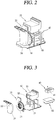
FIG. 2 is a perspective view of a some components of the clothes treating apparatus illustrated inFIG. 1 . -
FIG. 3 is an exploded perspective view of some components of the clothes treating apparatus illustrated inFIG. 1 . -
FIG. 4 is a block diagram of the clothes treating apparatus illustrated inFIG. 1 . -
FIG. 5 is a flow chart illustrating an operation of a clothes treating apparatus according to an embodiment of the present disclosure. -
FIGS. 6A to 6D are views illustrating components of a clothes treating apparatus according to an embodiment of the present disclosure. -
FIG. 7 is a flow chart illustrating a control method of a clothes treating apparatus according to an embodiment of the present disclosure. - Description will now be given in detail of the exemplary embodiments, with reference to the accompanying drawings. For the sake of brief description with reference to the drawings, the same or equivalent components will be provided with the same reference numbers, and description thereof will not be repeated.
- Hereinafter, a clothes treating apparatus and a control method thereof according to embodiments of the present disclosure will be described with reference to the accompanying drawings.
-
FIG. 1 is a perspective view of a clothes treating apparatus according to an embodiment of the present disclosure,FIG. 2 is a perspective view of a some components of the clothes treating apparatus illustrated inFIG. 1 ,FIG. 3 is an exploded perspective view of some components of the clothes treating apparatus illustrated inFIG. 1 , andFIG. 4 is a block diagram of the clothes treating apparatus illustrated inFIG. 1 . - The clothes treating apparatus according to an embodiment of the present disclosure includes a
case 10 including atreatment chamber 12 for holding clothes, asteam unit 40 for supplying steam to thetreatment chamber 12, a blowingunit 30 for intaking air from the inside of thetreatment chamber 12, aninlet temperature sensor 39 measuring an inlet temperature as a temperature value of air intaken to theblowing unit 30, aheat pump unit 50 for heating air intaken by the blowingunit 30 and discharging heated air to thetreatment chamber 12, and acontrol unit 60 controlling thesteam unit 40, the blowingunit 30, and theheat pump unit 50. - The
case 10 has aseparator 11 dividing the inside of thecase 10 in a vertical direction, thetreatment chamber 12 holding clothes is provided above theseparator 11 and acycle chamber 14 in which a mechanical device is provided below theseparator 11. - The case has a door configured to open and close a front side of the
case 10. - The
treatment chamber 12 holds clothes, wherein during operation of the clothes treatment apparatus wrinkles are removed or the clothes is deodorized through steaming, air circulation, drying, and the like. - In the
cycle chamber 14, the blowingunit 30 intaking air from the inside of thetreatment chamber 12 and circulating the intaken air, thesteam unit 40 supplying steam to thetreatment chamber 12, theheat pump unit 50 supplying heated air to thetreatment chamber 12, and thecontrol unit 60 controlling theunits - The blowing
unit 30 intakes air from the inside of thetreatment chamber 12 under the control of thecontrol unit 60. Air intaken to theblowing unit 30 is discharged to theheat pump unit 50. - The blowing
unit 30 includes a blowingfan module 32 moving air through rotation of a fan to intake air from the inside of thetreatment chamber 12 and subsequently discharging the intaken air to theheat pump unit 50 and aninlet duct 34 installed on an intaking side of the blowingfan module 32 and guiding air within thetreatment chamber 12 to the blowingfan module 32. - One side of the
inlet duct 34 is connected to thetreatment chamber 12 and the other side thereof is connected to the blowingfan module 32. Theinlet temperature sensor 39 measuring an inlet temperature as a temperature value of air moving within theinlet duct 34 is provided within theinlet duct 34. Theinlet temperature sensor 39 measures an inlet temperature as a temperature value of air intaken to the inside of theinlet duct 34 from thetreatment chamber 12 and transfers the measured inlet temperature to thecontrol unit 60. - One side of the blowing
fan module 32 is connected to theinlet duct 34, and the other side thereof is connected to theheat pump unit 50. The blowingfan module 32 is a single module including a duct, and a motor and preferably a sirroco fan. - The
steam unit 40 supplies steam to thetreatment chamber 12 under the control of thecontrol unit 60. Thesteam unit 40 is heated by power applied thereto, receives water stored in a storage tank and heats the received water to convert the water into steam. - Steam generated by the
steam unit 40 is discharged to thetreatment chamber 12. In the present embodiment, steam generated by thesteam unit 40 moves to thetreatment chamber 12 through a flow channel of theheat pump unit 50. That is, thesteam unit 40 is preferably connected to theheat pump unit 50. - The
steam unit 40 includes aheater 41 heating water. Thesteam unit 40 performs preheating to first heat theheater 41 and subsequently generates steam under the control of thecontrol unit 60. - The
heat pump unit 50 heats air intaken by the blowingunit 30 and discharges the heated air to the inside of thetreatment chamber 12 under the control of thecontrol unit 60. - The
heat pump unit 50 is configured as a refrigerating cycle including acompressor 51, acondenser 53, an evaporator (not shown), and an expansion valve (not shown), and includes a heatpump flow channel 55, in which thecondenser 53 is installed, forming a flow channel. - The
compressor 51 compresses a refrigerant to make the refrigerant in a high temperature and high pressure state. Thecondenser 53 heat-exchanges the refrigerant compressed in thecompressor 51 with air intaken to theblowing unit 30 to heat air. The expansion valve expands the refrigerant condensed in the condenser, and the evaporator evaporates the refrigerant expanded in the expansion valve to collect the refrigerant by thecompressor 51. - One side of the heat
pump flow channel 55 is connected to the blowingfan module 32 of the blowingunit 30, and the other side thereof is connected to thetreatment chamber 12. Thecondenser 53 is disposed within the heatpump flow channel 55. - A
tank module 70 storing water is installed in thecycle chamber 14, preferably in front of thecycle chamber 12 and in the present embodiment, atank module frame 71 in which thetank module 70 is installed is installed in front of theinlet duct 34. - The
tank module 70 includes astorage tank 80 storing water supplied to thesteam unit 40 and adrain tank 90 collecting and storing condensate generated in thetreatment chamber 12. Thestorage tank 80 is connected to thesteam unit 40 to supply water, and thedrain tank 90 is connected to thetreatment chamber 12 and stores water condensed in thetreatment chamber 12 or theheat pump unit 50. - The
control unit 60 receives an inlet temperature from theinlet temperature sensor 39. Thecontrol unit 60 performs each operation to treat clothes in the clothes treating apparatus according to a preset course by controlling thesteam unit 40, the blowingunit 30, and theheat pump unit 50 according to a user setting or an inlet temperature. Each operation to treat clothes will be described with reference toFIG. 5 hereinafter. - The
control unit 60 controls an operation of theheat pump unit 50 on the basis of a preheating inlet temperature measured by theinlet temperature sensor 39 by operating the blowingunit 30, while preheating thesteam unit 40. -
FIG. 5 is a flow chart illustrating an operation of a clothes treating apparatus according to an embodiment of the present disclosure. - In
FIG. 5 , operations of a general course are illustrated, and some of operations may be omitted or order of the operations may be interchanged. - When a user starts to operate the clothes treating apparatus, the
control unit 60 performs a preheating operation to preheat theheater 41 of thesteam unit 40 by supplying power to the heater 41 (S210). - In the preheating operation (S210), the
control unit 60 operates the blowingfan module 32 of the blowingunit 30. When the blowingfan module 32 operates, theinlet temperature sensor 39 measures temperature of air intaken to theinlet duct 34 of the blowingunit 30 and transfers the measured preheating inlet temperature to thecontrol unit 60. - When preheating of the
heater 41 is completed, thecontrol unit 60 performs a steam operation (S220). Thecontrol unit 60 supplies water stored in thestorage tank 80 to thesteam unit 40 to generate steam, and supplies steam to the inside of thetreatment chamber 12. Thecontrol unit 60 operates the blowingfan module 32 to circulate air within thetreatment chamber 12. During the steam operation (S220), theheat pump unit 50 does not operate. - When a preset period of time has elapsed, the
control unit 60 stops operation of thesteam unit 40 to terminate the steam operation (S220). - After the steam operation (S220), the
control unit 60 performs a standby operation (or waiting operation) (S230) and a cooling operation (S240). After the operation of thesteam unit 40 is stopped, thecontrol unit 60 performs the standby operation (S230) such that steam may be sufficiently applied to the clothes, while rotating the blowingfan module 32 at a relatively low RPM. - When a preset period of time has elapsed, the
control unit 60 performs a cooling operation (S240) to decrease temperature within thetreatment chamber 12, while rotating the blowingfan module 32 at a relatively high RPM. - When a preset period of time has elapsed, the
control unit 60 terminates the cooling operation (S240). - After the cooling operation (S240), the
control unit 60 performs a dry operation (S250) to supply heated air to the inside of thetreatment chamber 12 by driving the blowingfan module 32 and driving thecompressor 51 of theheat pump unit 50. - Hereinafter, components of the
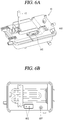
steam unit 40 will be described in detail with reference toFIGS. 6A to 6D . - As illustrated in
FIGS. 6A to 6C , thesteam unit 40 may include awater supply tank 603 accommodating water for generating steam, theheater 41 heating water accommodated in thewater supply tank 603, andwater level sensors - Referring to
FIG. 6C , the water level sensors may include a firstwater level sensor 601 and a secondwater level sensor 602. A length of the firstwater level sensor 601 may be different from that of the secondwater level sensor 602. - That is, the first and second
water level sensors water level sensors water level sensors water level sensors - For example, the first
water level sensor 601 and the secondwater level sensor 602 may be an electrode sensor, and when a portion of the electrode sensor is in contact with water, a current may flow in the electrode sensor. - In detail, referring to
FIG. 6C , the first and secondwater level sensors water level sensor 601 may be longer than the secondwater level sensor 602, and thus, the firstwater level sensor 601 may contact water at a lower level than the secondwater level sensor 602. - Hereinafter, when the water level sensor is determined to be in contact with water, it is defined that the water level sensor is ON. Conversely, when the water level sensor is determined not to be in contact with water. it is defined that the water level sensor is OFF.
- In an embodiment, when the first and second
water level sensors control unit 60 may determine that a water level of the water supply tank is low. Also, when the firstwater level sensor 601 is ON and the secondwater level sensor 602 is OFF, thecontrol unit 60 may determine that a water level of the water supply tank is low. - Also, when the first and second
water level sensors control unit 60 may determine that a water level of the water supply tank is high. - Meanwhile, when the first
water level sensor 601 is OFF and the secondwater level sensor 602 is ON, thecontrol unit 60 may determine that information related to a water level of the water supply tank is detected to be erroneous. - In
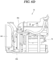
FIG. 6D , components of the clothes treating apparatus connected to thesteam unit 40 are illustrated. - A
water supply valve 604, awater supply pump 605, and awater tank 606 may be connected to a flow channel transferring water to thesteam unit 60. - First, the
water supply valve 604 may be opened or closed on the basis of an electrical signal generated by thecontrol unit 60. - The
water tank 606 may temporarily store water before transferring water to thesteam unit 40. Also, thewater supply pump 605 may generate driving force to supply water to thesteam unit 40. - The
control unit 60 may adjust an amount of water supplied to the water supply tank by controlling at least one of an operation time of thewater supply pump 605 and an opening time of thewater supply valve 604. - In an embodiment, the
control unit 60 of the clothes treating apparatus according to the present disclosure may detect whether thesteam unit 40 was driven during an operation performed in a previous cycle, and determine whether a result of sensing by the water level sensor is erroneous on the basis of a detection result. - For example, when both the first and second water level sensors are ON although the
steam unit 40 was driven in a previous operation, thecontrol unit 60 may determine that a result of sensing by the water level sensor is erroneous. - Also, in another example, when only the second water level sensor is ON although the
steam unit 40 was driven in a previous operation, thecontrol unit 60 may determine that a result of sensing by the water level sensor is erroneous. - In detail, when the
heat pump unit 50 is driven after thesteam unit 40 is driven, thecontrol unit 60 may supply water to thesteam unit 40 after driving of theheat pump unit 50 terminates. - That is, after driving of the
steam unit 40 and driving of theheat pump unit 50 sequentially terminate, thecontrol unit 60 may detect an amount of water remaining in thesteam unit 40. In addition, thecontrol unit 60 may supply water to thesteam unit 40 on the basis of the sensing result. - After driving of the
steam unit 40 and driving of theheat pump unit 50 sequentially terminate, when it is determined that an amount of water remaining in thesteam unit 40 is equal to or greater than a predetermined value, thecontrol unit 60 may determine that the amount of water remaining in thesteam unit 40 was erroneously sensed. - Here, after driving of the
steam unit 40 and driving of theheat pump unit 50 sequentially terminate, when both the first and secondwater level sensors water level sensor 602 is ON, thecontrol unit 60 may determine that an amount of water remaining in thesteam unit 40 was erroneously sensed. - When it is determined that the amount of water remaining in the
steam unit 40 was erroneously sensed, thecontrol unit 60 may supply water to thesteam unit 40 on the basis of an amount of steam generated by thesteam unit 40 before sensing an amount of water remaining in thesteam unit 40. - When it is determined that an amount of water remaining in the
steam unit 40 was erroneously sensed, thecontrol unit 60 may control thewater supply pump 605 and thewater supply valve 604 to supply water to thesteam unit 40 on the basis of an amount of steam generated by thesteam unit 40 before sensing an amount of water remaining in thesteam unit 40. - When it is determined that an amount of water remaining in the
steam unit 40 was erroneously sensed, thecontrol unit 60 may open thewater supply valve 604, and when a preset period of time has elapsed since thewater supply valve 604 was opened, thecontrol unit 60 may drive the water supply pump. Here, for example, the preset period of time may be 3 seconds. - The
control unit 60 may set a first limitation driving time on the basis of a time during which thesteam unit 40 was driven before sensing an amount of water remaining in thesteam unit 40. Also, when the driving time of thewater supply pump 605 exceeds the first limitation driving time, thecontrol unit 60 may stop thewater supply pump 605. - For example, the first limitation driving time may be a value obtained by multiplying a preset constant α to a time during which the
steam unit 40 was driven in an immediately previous operation. - The
control unit 60 may set the constant α using data related to a driving time of thesteam unit 40, an amount of water evaporated in thesteam unit 40, a driving time of thewater supply pump 605, and an amount of water supplied by thewater supply pump 605. - The
control unit 60 may set the constant α such that 85% of an amount of water evaporated in a steam operation of a previous stage is supplied to thesteam unit 40. Here, the value 85% is set according to experiment, and when thecontrol unit 60 supplies 85% of the amount of water evaporated in the steam operation of a previous stage is supplied to thesteam unit 40, overflow of water from the water supply tank of thesteam unit 40 may be prevented. - Meanwhile, after driving of the
steam unit 40 and driving of theheat pump unit 50 sequentially terminate, when water is sensed in both of the first and secondwater level sensors control unit 60 may process the result of sensing by the water level sensors, as an error. - In an example, the
control unit 60 may set a count variable for calculating an error number of the water level sensors to 0 at an initial stage, and whenever a result of sensing by the water level sensors is processed as an error, thecontrol unit 60 may increase the count variable by 1 each time. - When the result of sensing by the water level sensors is processed as an error, the
control unit 60 may control the water supply pump and the water supply valve to supply water to thesteam unit 40 on the basis of an amount of steam generated by thesteam unit 40 before sensing an amount of water remaining in thesteam unit 40. - Meanwhile, although not shown, the clothes treating apparatus according to the present disclosure may include a display unit (not shown) for outputting information related to a state of the clothes treating apparatus.
- In an embodiment, the
control unit 60 may calculate the number of times a sensing result of the water level sensor was processed as an error, and when the calculated number exceeds a limitation number, thecontrol unit 60 may control the display unit to output an error message. Here, for example, the limitation number may be 5 times. - Also, in another embodiment, the
control unit 60 may calculate the number of times a sensing result of the water level sensor was processed as an error, and when the calculated number exceeds a limitation number, thecontrol unit 60 may stop the operation of the clothes treating apparatus and drain water remaining in the water supply tank. - In another embodiment, when draining of water remaining in the water supply tank is completed, the
control unit 60 may control the water supply valve and the water supply pump to re-supply a preset amount of water to the water supply tank. The preset amount of water may be 80% of capacity of the water supply tank. - Meanwhile, after driving of the steam unit and driving of the
heat pump unit 50 sequentially terminate, when it is determined that an amount of water remaining in the steam unit is equal to or smaller than a predetermined value, thecontrol unit 60 may supply water to the steam unit until the amount of water remaining in the steam unit exceeds the predetermined value. - For example, after driving of the
steam unit 40 and driving of theheat pump unit 50 sequentially terminate, when the firstwater level sensor 601 is ON and the secondwater level sensor 602 is OFF, thecontrol unit 60 may determine that the amount of water remaining in thesteam unit 40 is equal to or smaller than the predetermined value. - In this case, the
control unit 60 may supply water to thesteam unit 40 until the secondwater level sensor 602 is turned on. Also, thecontrol unit 60 may drive the water supply pump within a preset second limitation time (β seconds) to supply water to thesteam unit 40. In this manner, by setting the second limitation driving time, overflow of water from the water tank due to malfunction of the second water level sensor may be prevented. - In another embodiment, the
control unit 60 of the clothes treating apparatus according to the present disclosure may perform a pre-steam operation to heat water remaining in thesteam unit 40, a steam operation to supply steam to the treatment chamber using heated water, and a dry operation to supply heated air to the treatment chamber. - After completing the dry operation, the
control unit 60 may determine whether the steam operation was performed before the steam operation was performed. - When it is determined that the steam operation was performed before the dry operation was performed, the
control unit 60 may supply water to the steam unit. - In detail, when it is determined that the steam operation was performed before the dry operation was performed, the
control unit 60 may detect information related to a water level of thesteam unit 40. When it is determined that a water level of the steam unit exceeds a predetermined water level value, thecontrol unit 60 may determine that the water level of thesteam unit 40 was erroneously sensed. - The
control unit 60 may supply water to thesteam unit 40 on the basis of an amount of steam generated during the steam operation performed before the water level of thesteam unit 40 was erroneously sensed. - The
control unit 60 may supply water to thesteam unit 40 on the basis of a time during which the steam operation was performed before the water level of thesteam unit 40 was erroneously sensed. - Hereinafter, a method for controlling a clothes treating apparatus according to the present disclosure will be described with reference to
FIG. 7 . - The
control unit 60 may control theheat pump unit 50 to perform a dry operation (S701). - When the dry operation is completed, the
control unit 60 may determine whether the steam operation is performed before the dry operation (S702). - When it is determined that the steam operation is performed before the dry operation, the
control unit 60 may sense a water level of the water supply tank using a sensing result from the water level sensor provided in the steam unit 40 (S703). - Here, the
control unit 60 may determine whether the second water level sensor is ON (S704). When the second water level sensor is ON, thecontrol unit 60 may determine that a water level of the water supply tank was erroneously sensed, and perform an algorithm to cope with the erroneous sensing. - Meanwhile, the
control unit 60 may detect a time during which the steam operation was performed before the dry operation, and determine whether the time during which the steam operation was performed exceeds a preset period of time. Also, only when the time during which the steam operation was performed exceeds the preset period of time, thecontrol unit 60 may perform the algorithm to cope with the erroneous sensing. - For example, in cases where the steam operation immediately before the dry operation was performed for 3 minutes or less, the
control unit 60 may not perform the algorithm to cope with the erroneous sensing and determine whether to supply water to the water supply tank on the basis of a sensing result from the water level sensor. - Referring to
FIG. 7 , thecontrol unit 60 opens the water supply valve (S705a), and after a predetermined period of time (t seconds) has elapsed (S706a), thecontrol unit 60 may drive the water supply pump (S707a). - In particular, the
control unit 60 may determine whether a driving time of the water supply pump exceeds a time value obtained by multiplying a preset constant α to the time during which the steam operation was maintained previously (S708a). - When the driving time of the water supply pump exceeds the time value obtained by multiplying the preset constant α to the time during which the steam operation was maintained previously, the
control unit 60 may shut the water supply valve and stop the water supply pump (S709). - Meanwhile, when it is determined that the second water level sensor is OFF, the
control unit 60 may perform a general water supply algorithm. - That is, the
control unit 60 opens the water supply valve (S705b), and after the lapse of a predetermined period of time (t seconds) (S706), thecontrol unit 60 may drive the water supply pump (S707b). - In addition, the
control unit 60 may determine whether the second water level sensor is switched to ON, while the water supply pump is being driven (S708b). - Also, the
control unit 60 may determine whether a driving time of the water supply pump exceeds a second limitation driving time (β seconds) (S708c). - When the second water level sensor is switched to ON or when the driving time of the water supply pump exceeds the second limitation driving time (β seconds), the
control unit 60 may shut the water supply valve and stop the water supply pump (S709). - As described above, since the clothes treating apparatus according to the present disclosure is equipped with the control algorithm for complementing erroneous sensing of the water level sensor, an amount of water remaining in the tank may be accurately sensed without using an extra sensor.
- Also, according to the present disclosure, since water is forcibly supplied to the tank regardless of a sensing result from the water level sensor after the steam function is performed, application of heat to the tank without water may be prevented.
- Also, according to the present disclosure, since the control algorithm is performed such that heat is not applied to the tank without water, breakdown of the heat applying heat to the tank to generate steam may be prevented.
- Also, according to the present disclosure, overflow of water from tank may be prevented by adjusting an amount of water supplied to the tank in consideration of a time during which the steam function is performed.
- Also, according to the present disclosure, since breakdown of the clothes treating apparatus due to erroneous sensing of the water level sensor is prevented without using any extra sensor, manufacturing cost of the clothes treating apparatus may not be increased and the user of the clothes treating apparatus may save cost incurred due to breakdown.
- Also, according to the present disclosure, when it is determined that the water level sensor erroneously operates a plurality of times, a message related to the erroneous operation is sent to the user, and thus, breakdown of the clothes treating apparatus may be prevented in advance.
- The foregoing embodiments and advantages are merely exemplary and are not to be considered as limiting the present disclosure. The present teachings can be readily applied to other types of apparatuses. This description is intended to be illustrative, and not to limit the scope of the claims. Many alternatives, modifications, and variations will be apparent to those skilled in the art. The features, structures, methods, and other characteristics of the exemplary embodiments described herein may be combined in various ways to obtain additional and/or alternative exemplary embodiments.
- As the present features may be embodied in several forms without departing from the characteristics thereof, it should also be understood that the above-described embodiments are not limited by any of the details of the foregoing description, unless otherwise specified, but rather should be considered broadly within its scope as defined in the appended claims, and therefore all changes and modifications that fall within the metes and bounds of the claims, or equivalents of such metes and bounds are therefore intended to be embraced by the appended claims.
Claims (13)
- A clothes treating apparatus comprising:a case (10) including a treatment chamber (12) configured to hold clothes;a steam unit (40) configured to supply steam to the treatment chamber (12);a blowing unit (30) configured to intake air from the inside of the treatment chamber (12);a heat pump unit (50) configured to heat air intaken by the blowing unit (30) and to discharge heated air to the inside of the treatment camber (12); anda control unit (60) configured to control the steam unit (40), the blowing unit (30), and the heat pump unit (50);the control unit (60) is configured to supply water to the steam unit (40) after driving of the heat pump unit (50) terminates when the heat pump unit (50) is driven after the steam unit (40) is driven;characterized in that:
the control unit (60) is configured to determine that the amount of water remaining in the steam unit (40) was erroneously sensed when after driving of the steam unit (40) and driving of the heat pump unit (50) sequentially terminate, an amount of water remaining in the steam unit (40) is determined to be equal to or greater than a predetermined value, , wherein, after driving of the steam unit (40) and driving of the heat pump unit (50) sequentially terminate, the control unit is configured to sense an amount of water remaining in the steam unit (40) and to supply water to the steam unit (40) on the basis of a sensing result. - The clothes treating apparatus of claim 1, wherein, when it is determined that the amount of water remaining in the steam unit (40) was erroneously sensed, the control unit (60) is configured to supply water to the steam unit (40) on the basis of an amount of steam generated by the steam unit (40) before the amount of water remaining in the steam unit (40) was sensed.
- The clothes treating apparatus as claimed in any one of the preceding claims, further comprising:a water supply pump (605) supplying water to the steam unit (40); anda water supply valve (604) provided to a flow channel connected to an inlet of the water supply pump (605),wherein when it is determined that an amount of water remaining in the steam unit (40) was erroneously sensed, the control unit (60) is configured to control the water supply pump (605) and the water supply valve (604) to supply water to the steam unit (40) on the basis of an amount of steam generated by the steam unit (40) before the amount of steam remaining in the steam unit (40) was sensed.
- The clothes treating apparatus of claim 3, wherein, when it is determined that an amount of water remaining in the steam unit (40) was erroneously sensed, the control unit (60) is configured to open the water supply valve (604), and when a preset period of time has elapsed since the water supply valve (604) was opened, the control unit (60) is configured to drive the water supply pump (605).
- The clothes treating apparatus of claim 3 or 4, wherein the control unit (60) is configured to set a first limitation driving time on the basis of a time during which the steam unit (40) is driven before the amount of water remaining in the steam unit (40) was sensed, and when the driving time of the water supply pump (605) exceeds the first limitation driving time, the control unit (60) is configured to stop the water supply pump (605).
- The clothes treating apparatus of claim 1, wherein the steam unit (40) includes:a water supply tank (603) configured to accommodate water for generating steam;a heater (41) configured to heat water accommodated in the water supply tank (603); anda water level sensor (601, 602) configured to sense a water level in the water supply tank (603).
- The clothes treating apparatus of claim 6, whereinthe water level sensor includes a first water level sensor (601) and a second water level sensor (602) provided to have different lengths, andwhen both the first and second water level sensors (601, 602) are configured to sense water after driving of the steam unit (40) and driving of the heat pump unit (50) sequentially terminate, the control unit (60) is configured to process a sensing result from the water level sensor as an error.
- The clothes treating apparatus of claim 6 or 7, wherein, when the sensing result from the water level sensor (601, 602) is processed as an error, the control unit (60) is configured to supply water to the steam unit (40) on the basis of an amount of steam generated by the steam unit (40) before the amount of water remaining in the steam unit (40) was sensed.
- The clothes treating apparatus as claimed in any one of the preceding claims, further comprising:a display unit configured to output information related to a state of the clothes treating apparatus,wherein the control unit (60) is configured to calculate the number of times the sensing result from the water level sensor (601, 602) is processed as an error, and when the calculated number of times exceeds a limitation number, the control unit (60) is configured to control the display unit to output an error message.
- The clothes treating apparatus of claim 7, 8 or 9, wherein the control unit (60) is configured to calculate the number of times the sensing result from the water level sensor (601, 602) is processed as an error, and when the calculated number of times exceeds a limitation number, the control unit (60) is configured to stop an operation of the clothes treating apparatus and drain water remaining in the water supply tank (603).
- The clothes treating apparatus of claim 7, wherein, when draining of water remaining in the water supply tank (603) is completed, the control unit (60) is configured to re-supply a preset amount of water to the water supply tank (603).
- The clothes treating apparatus as claimed in any one of the preceding claims, wherein, after driving of the steam unit (40) and driving of the heat pump unit (50) sequentially terminate, when an amount of water remaining in the steam unit (40) is equal to or smaller than a predetermined value, the control unit (60) is configured to supply water to the steam unit (40) until the amount of water remaining in the steam unit (40) exceeds the predetermined value.
- The clothes treating apparatus as claimed in any one of the preceding claims, further comprising:a water supply pump (605) supplying water to the steam unit (40),wherein the control unit (60) is configured to drive the water supply pump (605) during a preset second limitation driving time to supply water to the steam unit (40).
Applications Claiming Priority (1)
| Application Number | Priority Date | Filing Date | Title |
|---|---|---|---|
| KR1020170048719A KR102367886B1 (en) | 2017-04-14 | 2017-04-14 | Clothes treating apparatus |
Publications (2)
| Publication Number | Publication Date |
|---|---|
| EP3388570A1 EP3388570A1 (en) | 2018-10-17 |
| EP3388570B1 true EP3388570B1 (en) | 2019-12-25 |
Family
ID=61972047
Family Applications (1)
| Application Number | Title | Priority Date | Filing Date |
|---|---|---|---|
| EP18167005.0A Active EP3388570B1 (en) | 2017-04-14 | 2018-04-12 | Clothes treating apparatus |
Country Status (3)
| Country | Link |
|---|---|
| US (2) | US11053636B2 (en) |
| EP (1) | EP3388570B1 (en) |
| KR (2) | KR102367886B1 (en) |
Families Citing this family (20)
| Publication number | Priority date | Publication date | Assignee | Title |
|---|---|---|---|---|
| KR20200025946A (en) * | 2018-08-31 | 2020-03-10 | 삼성전자주식회사 | Clothes care apparatus and control method thereof |
| KR102627707B1 (en) | 2018-11-30 | 2024-01-23 | 삼성전자주식회사 | Clothes care apparatus and control method thereof |
| KR102141078B1 (en) * | 2019-05-13 | 2020-08-05 | (주)신우엠테크 | Steamer |
| CN112011983A (en) * | 2019-05-28 | 2020-12-01 | 青岛海尔滚筒洗衣机有限公司 | Clothes treatment equipment and control method |
| KR102747204B1 (en) * | 2019-06-13 | 2024-12-27 | 삼성전자주식회사 | Clothes care apparatus |
| CN112481967A (en) * | 2019-08-20 | 2021-03-12 | 青岛海尔洗衣机有限公司 | Cabinet type clothes treatment equipment and control method thereof |
| KR102793625B1 (en) | 2019-12-11 | 2025-04-11 | 삼성전자주식회사 | Clothes Care Device and Control Method thereof |
| KR102857850B1 (en) * | 2019-12-12 | 2025-09-10 | 삼성전자주식회사 | Steam generator and clothes care apparatus having the same |
| US11578453B2 (en) * | 2020-03-26 | 2023-02-14 | Haier Us Appliance Solutions, Inc. | Fault detection for a water level detection system of a washing machine appliance |
| KR102367315B1 (en) * | 2020-05-14 | 2022-02-24 | 주식회사 대창 | Steamer and apparatus for supplying steam thereof |
| KR102367321B1 (en) * | 2020-05-14 | 2022-02-24 | 주식회사 대창 | Steamer and apparatus for supplying steam thereof |
| KR102525465B1 (en) * | 2021-04-26 | 2023-04-24 | 에스케이매직 주식회사 | Method for controlling laundry treatment |
| JP1749896S (en) * | 2021-05-21 | 2023-08-02 | Water tank for dehumidifying, deodorizing and wrinkle removing machine for clothes | |
| KR102742394B1 (en) * | 2021-07-21 | 2024-12-16 | 엘지전자 주식회사 | Laundry Treatment Apparatus and Control Method for the same |
| JP1755086S (en) * | 2021-12-17 | 2023-10-12 | Water tank for deodorizing, sterilizing, and steam generating equipment for shoe management | |
| WO2024065931A1 (en) * | 2022-09-29 | 2024-04-04 | 无锡小天鹅电器有限公司 | Clothing care device |
| CN117845582A (en) * | 2022-09-30 | 2024-04-09 | 青岛海尔洗衣机有限公司 | Control method of clothing care machine |
| KR20240099632A (en) | 2022-12-22 | 2024-07-01 | 엘지전자 주식회사 | Clothes care device and method, and a program therefor |
| KR20240099631A (en) | 2022-12-22 | 2024-07-01 | 엘지전자 주식회사 | Clothes care device and method, and a program therefor |
| KR20250072431A (en) * | 2023-11-16 | 2025-05-23 | 삼성전자주식회사 | Clothes Care Device and Control Method thereof |
Family Cites Families (15)
| Publication number | Priority date | Publication date | Assignee | Title |
|---|---|---|---|---|
| KR0172867B1 (en) * | 1995-11-23 | 1999-05-01 | 구자홍 | Dehydration control method of a washing machine |
| KR100666318B1 (en) * | 2003-08-13 | 2007-01-10 | 엘지전자 주식회사 | Steam generator for drum washing machine |
| JP3779977B2 (en) * | 2004-08-03 | 2006-05-31 | シャープ株式会社 | Steam cooker |
| US8168004B2 (en) * | 2005-03-25 | 2012-05-01 | Lg Electronics Inc. | Method for controlling operation of the washing machine |
| KR100672371B1 (en) * | 2005-03-25 | 2007-01-24 | 엘지전자 주식회사 | How to wash your laundry device |
| KR100672526B1 (en) * | 2005-03-25 | 2007-01-24 | 엘지전자 주식회사 | Laundry device and its control method |
| KR100793800B1 (en) * | 2006-06-30 | 2008-01-11 | 엘지전자 주식회사 | Washing machine and steam generator control method |
| EP1975308A1 (en) * | 2007-03-30 | 2008-10-01 | Koninklijke Philips Electronics N.V. | Method for determining the liquid level in a boiler |
| KR101306714B1 (en) | 2007-08-03 | 2013-09-11 | 엘지전자 주식회사 | device for cloth treating and method of the same |
| KR101430456B1 (en) | 2007-11-12 | 2014-08-18 | 엘지전자 주식회사 | Ancillary clothing processing equipment |
| KR101147774B1 (en) * | 2009-12-15 | 2012-05-29 | 엘지전자 주식회사 | Control method of clothes treatment apparatus |
| DE102011102878B4 (en) * | 2011-05-31 | 2014-10-23 | Rational Aktiengesellschaft | Method for controlling a steam generator |
| KR102214069B1 (en) | 2014-09-29 | 2021-02-09 | 엘지전자 주식회사 | Steam Generator and Laundry Treating Apparatus having the same |
| KR101597106B1 (en) * | 2014-12-19 | 2016-03-07 | 엘지전자 주식회사 | Apparatus for treating clothes |
| KR101597111B1 (en) | 2014-12-19 | 2016-02-24 | 엘지전자 주식회사 | Scent diffuser and fabric treating apparatus with the scent differ |
-
2017
- 2017-04-14 KR KR1020170048719A patent/KR102367886B1/en active Active
-
2018
- 2018-04-11 US US15/950,743 patent/US11053636B2/en active Active
- 2018-04-12 EP EP18167005.0A patent/EP3388570B1/en active Active
-
2021
- 2021-06-02 US US17/336,808 patent/US11718950B2/en active Active
-
2022
- 2022-02-22 KR KR1020220022839A patent/KR102434109B1/en active Active
Non-Patent Citations (1)
| Title |
|---|
| None * |
Also Published As
| Publication number | Publication date |
|---|---|
| KR20180116037A (en) | 2018-10-24 |
| US20210285150A1 (en) | 2021-09-16 |
| US20180298549A1 (en) | 2018-10-18 |
| EP3388570A1 (en) | 2018-10-17 |
| KR20220029609A (en) | 2022-03-08 |
| KR102367886B1 (en) | 2022-02-25 |
| US11053636B2 (en) | 2021-07-06 |
| KR102434109B1 (en) | 2022-08-19 |
| US11718950B2 (en) | 2023-08-08 |
Similar Documents
| Publication | Publication Date | Title |
|---|---|---|
| US11718950B2 (en) | Clothes treating apparatus | |
| EP2107149B1 (en) | Cloth treating apparatus and controlling method thereof | |
| EP2921587B1 (en) | Controlling method for drying machine with heat pump and heater | |
| CN107447473B (en) | Control method of clothes treatment device | |
| EP2935687B1 (en) | A method for controlling a laundry drying machine and a corresponding laundry drying machine | |
| JP6697477B2 (en) | Clothes processing device and control method thereof | |
| EP3418437B1 (en) | Clothes treating apparatus | |
| KR101366280B1 (en) | Cloth treating apparatus and Controlling method thereof | |
| JP4976965B2 (en) | Clothes dryer | |
| EP3077588B1 (en) | A method for controlling a laundry drying machine of the type comprising a heat pump system and a corresponding laundry drying machine | |
| US11060226B2 (en) | Laundry treating apparatus having induction heater and control method thereof | |
| KR101122094B1 (en) | Controlling method of laundry treatment apparutus | |
| CN101410565A (en) | Drum type washing machine and drying method thereof | |
| KR20090014054A (en) | Control Method of Clothing Processing Equipment |
Legal Events
| Date | Code | Title | Description |
|---|---|---|---|
| PUAI | Public reference made under article 153(3) epc to a published international application that has entered the european phase |
Free format text: ORIGINAL CODE: 0009012 |
|
| STAA | Information on the status of an ep patent application or granted ep patent |
Free format text: STATUS: REQUEST FOR EXAMINATION WAS MADE |
|
| 17P | Request for examination filed |
Effective date: 20180412 |
|
| AK | Designated contracting states |
Kind code of ref document: A1 Designated state(s): AL AT BE BG CH CY CZ DE DK EE ES FI FR GB GR HR HU IE IS IT LI LT LU LV MC MK MT NL NO PL PT RO RS SE SI SK SM TR |
|
| AX | Request for extension of the european patent |
Extension state: BA ME |
|
| RBV | Designated contracting states (corrected) |
Designated state(s): AL AT BE BG CH CY CZ DE DK EE ES FI FR GB GR HR HU IE IS IT LI LT LU LV MC MK MT NL NO PL PT RO RS SE SI SK SM TR |
|
| GRAP | Despatch of communication of intention to grant a patent |
Free format text: ORIGINAL CODE: EPIDOSNIGR1 |
|
| STAA | Information on the status of an ep patent application or granted ep patent |
Free format text: STATUS: GRANT OF PATENT IS INTENDED |
|
| INTG | Intention to grant announced |
Effective date: 20190729 |
|
| GRAS | Grant fee paid |
Free format text: ORIGINAL CODE: EPIDOSNIGR3 |
|
| GRAA | (expected) grant |
Free format text: ORIGINAL CODE: 0009210 |
|
| STAA | Information on the status of an ep patent application or granted ep patent |
Free format text: STATUS: THE PATENT HAS BEEN GRANTED |
|
| AK | Designated contracting states |
Kind code of ref document: B1 Designated state(s): AL AT BE BG CH CY CZ DE DK EE ES FI FR GB GR HR HU IE IS IT LI LT LU LV MC MK MT NL NO PL PT RO RS SE SI SK SM TR |
|
| REG | Reference to a national code |
Ref country code: GB Ref legal event code: FG4D |
|
| REG | Reference to a national code |
Ref country code: CH Ref legal event code: EP |
|
| REG | Reference to a national code |
Ref country code: AT Ref legal event code: REF Ref document number: 1217240 Country of ref document: AT Kind code of ref document: T Effective date: 20200115 |
|
| REG | Reference to a national code |
Ref country code: DE Ref legal event code: R096 Ref document number: 602018001738 Country of ref document: DE |
|
| REG | Reference to a national code |
Ref country code: IE Ref legal event code: FG4D |
|
| REG | Reference to a national code |
Ref country code: NL Ref legal event code: MP Effective date: 20191225 |
|
| PG25 | Lapsed in a contracting state [announced via postgrant information from national office to epo] |
Ref country code: FI Free format text: LAPSE BECAUSE OF FAILURE TO SUBMIT A TRANSLATION OF THE DESCRIPTION OR TO PAY THE FEE WITHIN THE PRESCRIBED TIME-LIMIT Effective date: 20191225 Ref country code: BG Free format text: LAPSE BECAUSE OF FAILURE TO SUBMIT A TRANSLATION OF THE DESCRIPTION OR TO PAY THE FEE WITHIN THE PRESCRIBED TIME-LIMIT Effective date: 20200325 Ref country code: LV Free format text: LAPSE BECAUSE OF FAILURE TO SUBMIT A TRANSLATION OF THE DESCRIPTION OR TO PAY THE FEE WITHIN THE PRESCRIBED TIME-LIMIT Effective date: 20191225 Ref country code: SE Free format text: LAPSE BECAUSE OF FAILURE TO SUBMIT A TRANSLATION OF THE DESCRIPTION OR TO PAY THE FEE WITHIN THE PRESCRIBED TIME-LIMIT Effective date: 20191225 Ref country code: GR Free format text: LAPSE BECAUSE OF FAILURE TO SUBMIT A TRANSLATION OF THE DESCRIPTION OR TO PAY THE FEE WITHIN THE PRESCRIBED TIME-LIMIT Effective date: 20200326 Ref country code: NO Free format text: LAPSE BECAUSE OF FAILURE TO SUBMIT A TRANSLATION OF THE DESCRIPTION OR TO PAY THE FEE WITHIN THE PRESCRIBED TIME-LIMIT Effective date: 20200325 Ref country code: LT Free format text: LAPSE BECAUSE OF FAILURE TO SUBMIT A TRANSLATION OF THE DESCRIPTION OR TO PAY THE FEE WITHIN THE PRESCRIBED TIME-LIMIT Effective date: 20191225 |
|
| REG | Reference to a national code |
Ref country code: LT Ref legal event code: MG4D |
|
| PG25 | Lapsed in a contracting state [announced via postgrant information from national office to epo] |
Ref country code: HR Free format text: LAPSE BECAUSE OF FAILURE TO SUBMIT A TRANSLATION OF THE DESCRIPTION OR TO PAY THE FEE WITHIN THE PRESCRIBED TIME-LIMIT Effective date: 20191225 Ref country code: RS Free format text: LAPSE BECAUSE OF FAILURE TO SUBMIT A TRANSLATION OF THE DESCRIPTION OR TO PAY THE FEE WITHIN THE PRESCRIBED TIME-LIMIT Effective date: 20191225 |
|
| PG25 | Lapsed in a contracting state [announced via postgrant information from national office to epo] |
Ref country code: AL Free format text: LAPSE BECAUSE OF FAILURE TO SUBMIT A TRANSLATION OF THE DESCRIPTION OR TO PAY THE FEE WITHIN THE PRESCRIBED TIME-LIMIT Effective date: 20191225 |
|
| PG25 | Lapsed in a contracting state [announced via postgrant information from national office to epo] |
Ref country code: NL Free format text: LAPSE BECAUSE OF FAILURE TO SUBMIT A TRANSLATION OF THE DESCRIPTION OR TO PAY THE FEE WITHIN THE PRESCRIBED TIME-LIMIT Effective date: 20191225 Ref country code: EE Free format text: LAPSE BECAUSE OF FAILURE TO SUBMIT A TRANSLATION OF THE DESCRIPTION OR TO PAY THE FEE WITHIN THE PRESCRIBED TIME-LIMIT Effective date: 20191225 Ref country code: RO Free format text: LAPSE BECAUSE OF FAILURE TO SUBMIT A TRANSLATION OF THE DESCRIPTION OR TO PAY THE FEE WITHIN THE PRESCRIBED TIME-LIMIT Effective date: 20191225 Ref country code: CZ Free format text: LAPSE BECAUSE OF FAILURE TO SUBMIT A TRANSLATION OF THE DESCRIPTION OR TO PAY THE FEE WITHIN THE PRESCRIBED TIME-LIMIT Effective date: 20191225 Ref country code: PT Free format text: LAPSE BECAUSE OF FAILURE TO SUBMIT A TRANSLATION OF THE DESCRIPTION OR TO PAY THE FEE WITHIN THE PRESCRIBED TIME-LIMIT Effective date: 20200520 |
|
| PG25 | Lapsed in a contracting state [announced via postgrant information from national office to epo] |
Ref country code: SK Free format text: LAPSE BECAUSE OF FAILURE TO SUBMIT A TRANSLATION OF THE DESCRIPTION OR TO PAY THE FEE WITHIN THE PRESCRIBED TIME-LIMIT Effective date: 20191225 Ref country code: IS Free format text: LAPSE BECAUSE OF FAILURE TO SUBMIT A TRANSLATION OF THE DESCRIPTION OR TO PAY THE FEE WITHIN THE PRESCRIBED TIME-LIMIT Effective date: 20200425 Ref country code: SM Free format text: LAPSE BECAUSE OF FAILURE TO SUBMIT A TRANSLATION OF THE DESCRIPTION OR TO PAY THE FEE WITHIN THE PRESCRIBED TIME-LIMIT Effective date: 20191225 |
|
| REG | Reference to a national code |
Ref country code: DE Ref legal event code: R097 Ref document number: 602018001738 Country of ref document: DE |
|
| PG25 | Lapsed in a contracting state [announced via postgrant information from national office to epo] |
Ref country code: ES Free format text: LAPSE BECAUSE OF FAILURE TO SUBMIT A TRANSLATION OF THE DESCRIPTION OR TO PAY THE FEE WITHIN THE PRESCRIBED TIME-LIMIT Effective date: 20191225 Ref country code: DK Free format text: LAPSE BECAUSE OF FAILURE TO SUBMIT A TRANSLATION OF THE DESCRIPTION OR TO PAY THE FEE WITHIN THE PRESCRIBED TIME-LIMIT Effective date: 20191225 |
|
| PLBE | No opposition filed within time limit |
Free format text: ORIGINAL CODE: 0009261 |
|
| STAA | Information on the status of an ep patent application or granted ep patent |
Free format text: STATUS: NO OPPOSITION FILED WITHIN TIME LIMIT |
|
| REG | Reference to a national code |
Ref country code: AT Ref legal event code: MK05 Ref document number: 1217240 Country of ref document: AT Kind code of ref document: T Effective date: 20191225 |
|
| PG25 | Lapsed in a contracting state [announced via postgrant information from national office to epo] |
Ref country code: SI Free format text: LAPSE BECAUSE OF FAILURE TO SUBMIT A TRANSLATION OF THE DESCRIPTION OR TO PAY THE FEE WITHIN THE PRESCRIBED TIME-LIMIT Effective date: 20191225 Ref country code: MC Free format text: LAPSE BECAUSE OF FAILURE TO SUBMIT A TRANSLATION OF THE DESCRIPTION OR TO PAY THE FEE WITHIN THE PRESCRIBED TIME-LIMIT Effective date: 20191225 |
|
| 26N | No opposition filed |
Effective date: 20200928 |
|
| PG25 | Lapsed in a contracting state [announced via postgrant information from national office to epo] |
Ref country code: AT Free format text: LAPSE BECAUSE OF FAILURE TO SUBMIT A TRANSLATION OF THE DESCRIPTION OR TO PAY THE FEE WITHIN THE PRESCRIBED TIME-LIMIT Effective date: 20191225 Ref country code: FR Free format text: LAPSE BECAUSE OF NON-PAYMENT OF DUE FEES Effective date: 20200430 Ref country code: LU Free format text: LAPSE BECAUSE OF NON-PAYMENT OF DUE FEES Effective date: 20200412 Ref country code: IT Free format text: LAPSE BECAUSE OF FAILURE TO SUBMIT A TRANSLATION OF THE DESCRIPTION OR TO PAY THE FEE WITHIN THE PRESCRIBED TIME-LIMIT Effective date: 20191225 |
|
| REG | Reference to a national code |
Ref country code: BE Ref legal event code: MM Effective date: 20200430 |
|
| PG25 | Lapsed in a contracting state [announced via postgrant information from national office to epo] |
Ref country code: BE Free format text: LAPSE BECAUSE OF NON-PAYMENT OF DUE FEES Effective date: 20200430 Ref country code: PL Free format text: LAPSE BECAUSE OF FAILURE TO SUBMIT A TRANSLATION OF THE DESCRIPTION OR TO PAY THE FEE WITHIN THE PRESCRIBED TIME-LIMIT Effective date: 20191225 |
|
| PG25 | Lapsed in a contracting state [announced via postgrant information from national office to epo] |
Ref country code: IE Free format text: LAPSE BECAUSE OF NON-PAYMENT OF DUE FEES Effective date: 20200412 |
|
| PG25 | Lapsed in a contracting state [announced via postgrant information from national office to epo] |
Ref country code: LI Free format text: LAPSE BECAUSE OF NON-PAYMENT OF DUE FEES Effective date: 20210430 Ref country code: CH Free format text: LAPSE BECAUSE OF NON-PAYMENT OF DUE FEES Effective date: 20210430 |
|
| PG25 | Lapsed in a contracting state [announced via postgrant information from national office to epo] |
Ref country code: TR Free format text: LAPSE BECAUSE OF FAILURE TO SUBMIT A TRANSLATION OF THE DESCRIPTION OR TO PAY THE FEE WITHIN THE PRESCRIBED TIME-LIMIT Effective date: 20191225 Ref country code: MT Free format text: LAPSE BECAUSE OF FAILURE TO SUBMIT A TRANSLATION OF THE DESCRIPTION OR TO PAY THE FEE WITHIN THE PRESCRIBED TIME-LIMIT Effective date: 20191225 Ref country code: CY Free format text: LAPSE BECAUSE OF FAILURE TO SUBMIT A TRANSLATION OF THE DESCRIPTION OR TO PAY THE FEE WITHIN THE PRESCRIBED TIME-LIMIT Effective date: 20191225 |
|
| PG25 | Lapsed in a contracting state [announced via postgrant information from national office to epo] |
Ref country code: MK Free format text: LAPSE BECAUSE OF FAILURE TO SUBMIT A TRANSLATION OF THE DESCRIPTION OR TO PAY THE FEE WITHIN THE PRESCRIBED TIME-LIMIT Effective date: 20191225 |
|
| GBPC | Gb: european patent ceased through non-payment of renewal fee |
Effective date: 20220412 |
|
| PG25 | Lapsed in a contracting state [announced via postgrant information from national office to epo] |
Ref country code: GB Free format text: LAPSE BECAUSE OF NON-PAYMENT OF DUE FEES Effective date: 20220412 |
|
| PGFP | Annual fee paid to national office [announced via postgrant information from national office to epo] |
Ref country code: DE Payment date: 20250305 Year of fee payment: 8 |