EP3388385B1 - Rotationsantrieb - Google Patents
Rotationsantrieb Download PDFInfo
- Publication number
- EP3388385B1 EP3388385B1 EP17166255.4A EP17166255A EP3388385B1 EP 3388385 B1 EP3388385 B1 EP 3388385B1 EP 17166255 A EP17166255 A EP 17166255A EP 3388385 B1 EP3388385 B1 EP 3388385B1
- Authority
- EP
- European Patent Office
- Prior art keywords
- shaft
- rotational drive
- rotary encoder
- recess
- shaft bearing
- Prior art date
- Legal status (The legal status is an assumption and is not a legal conclusion. Google has not performed a legal analysis and makes no representation as to the accuracy of the status listed.)
- Active
Links
Images


Classifications
-
- A—HUMAN NECESSITIES
- A01—AGRICULTURE; FORESTRY; ANIMAL HUSBANDRY; HUNTING; TRAPPING; FISHING
- A01G—HORTICULTURE; CULTIVATION OF VEGETABLES, FLOWERS, RICE, FRUIT, VINES, HOPS OR SEAWEED; FORESTRY; WATERING
- A01G23/00—Forestry
-
- A—HUMAN NECESSITIES
- A01—AGRICULTURE; FORESTRY; ANIMAL HUSBANDRY; HUNTING; TRAPPING; FISHING
- A01D—HARVESTING; MOWING
- A01D65/00—Grain-crop lifters
-
- B—PERFORMING OPERATIONS; TRANSPORTING
- B60—VEHICLES IN GENERAL
- B60P—VEHICLES ADAPTED FOR LOAD TRANSPORTATION OR TO TRANSPORT, TO CARRY, OR TO COMPRISE SPECIAL LOADS OR OBJECTS
- B60P1/00—Vehicles predominantly for transporting loads and modified to facilitate loading, consolidating the load, or unloading
- B60P1/54—Vehicles predominantly for transporting loads and modified to facilitate loading, consolidating the load, or unloading using cranes for self-loading or self-unloading
- B60P1/5404—Vehicles predominantly for transporting loads and modified to facilitate loading, consolidating the load, or unloading using cranes for self-loading or self-unloading with a fixed base
- B60P1/5423—Vehicles predominantly for transporting loads and modified to facilitate loading, consolidating the load, or unloading using cranes for self-loading or self-unloading with a fixed base attached to the loading platform or similar
-
- B—PERFORMING OPERATIONS; TRANSPORTING
- B66—HOISTING; LIFTING; HAULING
- B66C—CRANES; LOAD-ENGAGING ELEMENTS OR DEVICES FOR CRANES, CAPSTANS, WINCHES, OR TACKLES
- B66C13/00—Other constructional features or details
- B66C13/18—Control systems or devices
- B66C13/46—Position indicators for suspended loads or for crane elements
-
- B—PERFORMING OPERATIONS; TRANSPORTING
- B66—HOISTING; LIFTING; HAULING
- B66C—CRANES; LOAD-ENGAGING ELEMENTS OR DEVICES FOR CRANES, CAPSTANS, WINCHES, OR TACKLES
- B66C23/00—Cranes comprising essentially a beam, boom, or triangular structure acting as a cantilever and mounted for translatory of swinging movements in vertical or horizontal planes or a combination of such movements, e.g. jib-cranes, derricks, tower cranes
- B66C23/18—Cranes comprising essentially a beam, boom, or triangular structure acting as a cantilever and mounted for translatory of swinging movements in vertical or horizontal planes or a combination of such movements, e.g. jib-cranes, derricks, tower cranes specially adapted for use in particular purposes
- B66C23/36—Cranes comprising essentially a beam, boom, or triangular structure acting as a cantilever and mounted for translatory of swinging movements in vertical or horizontal planes or a combination of such movements, e.g. jib-cranes, derricks, tower cranes specially adapted for use in particular purposes mounted on road or rail vehicles; Manually-movable jib-cranes for use in workshops; Floating cranes
- B66C23/42—Cranes comprising essentially a beam, boom, or triangular structure acting as a cantilever and mounted for translatory of swinging movements in vertical or horizontal planes or a combination of such movements, e.g. jib-cranes, derricks, tower cranes specially adapted for use in particular purposes mounted on road or rail vehicles; Manually-movable jib-cranes for use in workshops; Floating cranes with jibs of adjustable configuration, e.g. foldable
-
- B—PERFORMING OPERATIONS; TRANSPORTING
- B66—HOISTING; LIFTING; HAULING
- B66C—CRANES; LOAD-ENGAGING ELEMENTS OR DEVICES FOR CRANES, CAPSTANS, WINCHES, OR TACKLES
- B66C23/00—Cranes comprising essentially a beam, boom, or triangular structure acting as a cantilever and mounted for translatory of swinging movements in vertical or horizontal planes or a combination of such movements, e.g. jib-cranes, derricks, tower cranes
- B66C23/54—Cranes comprising essentially a beam, boom, or triangular structure acting as a cantilever and mounted for translatory of swinging movements in vertical or horizontal planes or a combination of such movements, e.g. jib-cranes, derricks, tower cranes with pneumatic or hydraulic motors, e.g. for actuating jib-cranes on tractors
-
- B—PERFORMING OPERATIONS; TRANSPORTING
- B66—HOISTING; LIFTING; HAULING
- B66C—CRANES; LOAD-ENGAGING ELEMENTS OR DEVICES FOR CRANES, CAPSTANS, WINCHES, OR TACKLES
- B66C23/00—Cranes comprising essentially a beam, boom, or triangular structure acting as a cantilever and mounted for translatory of swinging movements in vertical or horizontal planes or a combination of such movements, e.g. jib-cranes, derricks, tower cranes
- B66C23/62—Constructional features or details
- B66C23/84—Slewing gear
- B66C23/86—Slewing gear hydraulically actuated
-
- B—PERFORMING OPERATIONS; TRANSPORTING
- B66—HOISTING; LIFTING; HAULING
- B66C—CRANES; LOAD-ENGAGING ELEMENTS OR DEVICES FOR CRANES, CAPSTANS, WINCHES, OR TACKLES
- B66C3/00—Load-engaging elements or devices attached to lifting or lowering gear of cranes or adapted for connection therewith and intended primarily for transmitting lifting forces to loose materials; Grabs
- B66C3/005—Grab supports, e.g. articulations; Oscillation dampers; Orientation
-
- E—FIXED CONSTRUCTIONS
- E02—HYDRAULIC ENGINEERING; FOUNDATIONS; SOIL SHIFTING
- E02F—DREDGING; SOIL-SHIFTING
- E02F3/00—Dredgers; Soil-shifting machines
- E02F3/04—Dredgers; Soil-shifting machines mechanically-driven
- E02F3/28—Dredgers; Soil-shifting machines mechanically-driven with digging tools mounted on a dipper- or bucket-arm, i.e. there is either one arm or a pair of arms, e.g. dippers, buckets
- E02F3/36—Component parts
- E02F3/3604—Devices to connect tools to arms, booms or the like
- E02F3/3677—Devices to connect tools to arms, booms or the like allowing movement, e.g. rotation or translation, of the tool around or along another axis as the movement implied by the boom or arms, e.g. for tilting buckets
- E02F3/3681—Rotators
-
- F—MECHANICAL ENGINEERING; LIGHTING; HEATING; WEAPONS; BLASTING
- F15—FLUID-PRESSURE ACTUATORS; HYDRAULICS OR PNEUMATICS IN GENERAL
- F15B—SYSTEMS ACTING BY MEANS OF FLUIDS IN GENERAL; FLUID-PRESSURE ACTUATORS, e.g. SERVOMOTORS; DETAILS OF FLUID-PRESSURE SYSTEMS, NOT OTHERWISE PROVIDED FOR
- F15B15/00—Fluid-actuated devices for displacing a member from one position to another; Gearing associated therewith
- F15B15/08—Characterised by the construction of the motor unit
- F15B15/12—Characterised by the construction of the motor unit of the oscillating-vane or curved-cylinder type
-
- F—MECHANICAL ENGINEERING; LIGHTING; HEATING; WEAPONS; BLASTING
- F15—FLUID-PRESSURE ACTUATORS; HYDRAULICS OR PNEUMATICS IN GENERAL
- F15B—SYSTEMS ACTING BY MEANS OF FLUIDS IN GENERAL; FLUID-PRESSURE ACTUATORS, e.g. SERVOMOTORS; DETAILS OF FLUID-PRESSURE SYSTEMS, NOT OTHERWISE PROVIDED FOR
- F15B15/00—Fluid-actuated devices for displacing a member from one position to another; Gearing associated therewith
- F15B15/20—Other details, e.g. assembly with regulating devices
- F15B15/28—Means for indicating the position, e.g. end of stroke
- F15B15/2815—Position sensing, i.e. means for continuous measurement of position, e.g. LVDT
Definitions
- the invention relates to a hydraulic rotary drive with the features of the preamble of claim 1.
- the EP 2 460 758 A1 shows a generic rotary drive.
- the hydraulic rotary drive according to the invention for rotating a load-bearing means relative to a crane arm also initially has a shaft which itself in turn has first fastening means for connecting the shaft to the load-bearing means or the crane arm.
- a shaft bearing is also provided, which has second fastening means for connecting the shaft bearing to the crane arm or the load-handling means.
- vanes arranged in the shaft are provided, which can be acted upon with oil to transmit a torque to the shaft via an oil supply and an oil discharge.
- the hydraulic rotary drive can generally be operated via a hydraulic device, which usually leads from a crane arm to the rotary drive.
- the rotary drive has a sliding contact device, which is electrically contacted with a power supply and a power take-off.
- an electrical consumer arranged on the rotary drive such as, for example, an electrically operated load handling device or an electrically operated work device, can be supplied with electrical energy.
- the sliding contact device can also be used for the rotatable feed-through of signal lines.
- a first recess is provided in the shaft for at least partial arrangement of the rotary encoder or sliding contact device and a second recess is provided in the shaft bearing for at least partial arrangement of the rotary encoder or sliding contact device.
- the rotary encoder can be arranged at least partially in the second recess and the sliding contact device can be arranged at least partially in the first recess. The reverse is also possible.
- the rotary encoder and / or the sliding contact device is or are essentially completely received in the at least one recess. As a result, a space-saving arrangement of the rotary encoder or the sliding contact device within the rotary drive and good protection against external mechanical influences can be achieved.
- the rotational position detected by the rotary encoder may be transmitted to a detection device in a wired or wireless manner.
- the rotary encoder can also be supplied with electrical power in a wired or wireless manner (for example inductively).
- the shaft at an end of the rotary drive facing the load handling device is via the Shaft bearing protrudes.
- fastening means for connecting the shaft to the load suspension means can easily be reached.
- the current discharge from the sliding contacting device is formed on the end of the rotary drive facing the load-handling means and preferably leads away laterally from the rotary drive.
- the lateral current discharge leads away from the sliding contacting device essentially radially or runs obliquely in the direction of the end of the rotary drive facing the load-handling means.
- the shaft is designed as a rotor and the shaft bearing as a stator.
- the shaft bearing can thus be designed to be non-rotatable relative to the crane arm and the shaft and, if appropriate, a load-bearing device arranged on it, can be rotated relative to the stationary shaft bearing.
- At least part of the rotary encoder is attached to the shaft bearing and at least part of the rotary encoder is attached to the shaft.
- part of the rotary encoder can be fixed relative to the shaft bearing and part of the rotary encoder can be fixed relative to the shaft.
- a rotation of the shaft relative to the shaft bearing can result in a rotation of the relevant parts of the rotary encoder with respect to one another and consequently can be detected.
- Protection is also sought after for a crane with a hydraulic rotary drive as described above for rotating a load-bearing means relative to a crane arm, the crane arm being connected to the second fastening means of the hydraulic rotary drive.
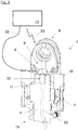
- FIG. 1 a section through a first embodiment of a rotary drive 1 is shown.
- the tab-shaped second fastening means 6 can be seen, with which the rotary drive 1 is attached, for example, to a crane arm 3 (not shown here, see FIG Figure 7 ) can be fastened.
- a rotatable shaft 4 is arranged in the shaft bearing 18 and has vanes 7 which can be acted upon by hydraulic oil in order to drive the shaft 4.
- the shaft 7 protrudes from the shaft bearing 18 at a lower end 15 of the rotary drive 1.
- a first recess 9 is provided in which a Rotary encoder 8 is arranged.
- the rotary encoder 8 is arranged essentially completely in the first recess 9.
- the first recess 9 is formed essentially between the tab-shaped second fastening means 6.
- a second recess 10, in which a sliding contact device 11 is arranged, is introduced at an end of the shaft 4 facing the second fastening means 6 (upper end as shown).
- the sliding contact device 11 is arranged essentially completely in the second recess 10.
- Corresponding recesses are provided in the shaft bearing 18 and in the shaft 4 for routing signal lines and / or supply lines.
- a recess in the form of the cable duct 20 in the shaft 4, which, as shown, runs essentially axially in the shaft 4 at least in sections, can be seen.
- a detection device 14 for detecting the sensor signals output by the rotary encoder 8 is shown schematically.
- the communication of the rotary encoder 8 with the detection device 14, which can for example be integrated in a crane control, can be wired via a signal line 22 and / or wirelessly via a radio link 23 (such as via Bluetooth, via a radio link according to a standard of the IEEE-802.11- Family or similar).
- the rotary encoder 8 and the detection device 14 can have corresponding radio modules.
- FIG 3 a second embodiment of a rotary drive 1 is shown.
- the shaft bearing 18 again has a first recess 9, in which a rotary encoder 8 is arranged.
- the shaft 4 has a second recess 10 in which a sliding contact device 11 is arranged.
- the cable duct 19 runs in the in Figure 2
- the embodiment shown in the shaft bearing 18 essentially radially and also opens into the rotary encoder 8 essentially radially.
- the axial cable duct 20, which, coming from the shaft 4, also opens axially into the rotary encoder 8, runs in the shaft 4.
- FIG 4 a third embodiment of a rotary drive 1 is shown.
- the shaft bearing 18 again has a first recess 9 in which a rotary encoder 8 is arranged.
- the shaft 4 has a second recess 10 in which a sliding contact device 11 is arranged.
- the power supply 12 of the sliding contact device 11 in the shaft bearing 18 runs essentially radially and further axially traverses the rotary encoder 8 through a corresponding axial passage 21.
- the current discharge 13 of the sliding contact device 11 runs, as shown, in the shaft 4 in the cable duct 20 essentially axially.
- the current discharge 13 emerges essentially axially from the end of the shaft 4 facing the first fastening means 5.
- the power supply 12 to the sliding contact device 11 thus runs radially in the shaft bearing 18 and radially in sections and axially in sections in the rotary encoder 8.
- the power supply 12 also runs axially.
- the current discharge 13 emerges essentially axially from the end of the shaft 4 facing the first fastening means 5.
- a fifth embodiment of a rotary drive 1 is shown which essentially differs from that in FIG Figure 4
- the embodiment shown differs in that the shaft 4 has a second recess 10 at an end facing away from the second fastening means 6 or facing the first fastening means 5, in which the sliding contacting device 11 is arranged.
- the rotary encoder 8 has a radial passage 21.
- the power supply 12 to the sliding contacting device 11 runs from the cable duct 19, which essentially runs radially through the shaft bearing 18, axially through the rotary encoder 8 and runs through the cable duct 20, which runs essentially axially through the shaft 4, to the sliding contacting device, which is arranged at the lower end of the shaft 4 as shown 11.
- the current discharge 13 emerges from the end of the shaft 4 facing the first fastening means 5, essentially axially.
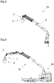
- FIG 7 a side view of a harvester 17, also called a wood harvester, forest harvester or crane harvester, is shown.
- the harvester 17 has a crane 16 with an outer crane arm 3.
- a rotary drive 1 is arranged, to which a load handling device 2 is attached.
- the load handling device 2 can be rotated relative to the crane arm 3 by the hydraulic rotary drive 1.
- a vehicle 24 is shown with a further embodiment of a crane 16 designed as a loading crane, structurally and functionally similar elements having the same reference numerals as in the previously shown embodiments.
- a load handling device 2 in the form of a gripper is arranged via a rotary drive 1.
Landscapes
- Engineering & Computer Science (AREA)
- Mechanical Engineering (AREA)
- General Engineering & Computer Science (AREA)
- Life Sciences & Earth Sciences (AREA)
- Physics & Mathematics (AREA)
- Fluid Mechanics (AREA)
- Environmental Sciences (AREA)
- Forests & Forestry (AREA)
- Ecology (AREA)
- Biodiversity & Conservation Biology (AREA)
- Automation & Control Theory (AREA)
- Mining & Mineral Resources (AREA)
- Civil Engineering (AREA)
- Structural Engineering (AREA)
- Transportation (AREA)
- Jib Cranes (AREA)
- Load-Engaging Elements For Cranes (AREA)
- Manipulator (AREA)
Description
- Die Erfindung betrifft einen hydraulischen Rotationsantrieb mit den Merkmalen des Oberbegriffs des Anspruchs 1.
- Bei gattungsgemäßen Rotationsantrieben, wie sie zum Beispiel bei Kränen zur rotierbaren Montage von Lastaufnahmemitteln zum Einsatz kommen, stellt sich die Erfassung der Drehstellung des Rotationsantriebs oft als schwierig dar. Die Drehstellung des Rotationsantriebs muss dabei beispielsweise durch einen Benutzer optisch erfolgen, was auch freie Einsicht auf den Rotationsantrieb bzw. freie Zugänglichkeit zum Rotationsantrieb voraussetzen kann. Dies kann sich negativ auf den Montagevorgang eines Lastaufnahmemittels am Rotationsantrieb sowie auf die Bedienung eines an einem Kran über einen herkömmlichen Rotationsantrieb montierten Lastaufnahmemittels auswirken.
- Die
EP 2 460 758 A1 zeigt einen gattungsgemäßen Rotationsantrieb. - Die
WO 2016/099372 A1 zeigt einen Rotator mit einer Vorrichtung zur Bestimmung der Drehstellung des Rotators, wobei die Vorrichtung einen den Rotator umschließenden Magnetring und einen Sensor aufweist. - Die
EP 3 504 145 A1 ist Stand der Technik nach Artikel 54(3) EPÜ. Sie zeigt einen hydraulischen Drehantrieb mit einem Rotor und einem Stator, sowie einem Winkelsensor zur Erfassung einer Winkelstellung des Rotors zum Stator. In der Welle ist eine Ausnehmung vorgesehen, in welcher der Winkelsensor teilweise aufgenommen ist. - Aufgabe der Erfindung ist es, einen verbesserten Rotationsantrieb anzugeben, bei welchem die zuvor genannten Nachteile nicht auftreten.
- Diese Aufgabe wird durch einen Rotationsantrieb mit den Merkmalen des Anspruchs 1 gelöst. Vorteilhafte Ausführungsformen der Erfindung sind in den abhängigen Ansprüchen definiert.
- Wie bei einem gattungsgemäßen weist auch der erfindungsgemäße hydraulische Rotationsantrieb zum Rotieren eines Lastaufnahmemittels relativ zu einem Kranarm zunächst eine Welle auf, welche selbst wiederum erste Befestigungsmittel zum Verbinden der Welle mit dem Lastaufnahmemittel oder dem Kranarm aufweist. Weiter ist ein Wellenlager vorgesehen, welches zweite Befestigungsmittel zum Verbinden des Wellenlagers mit dem Kranarm oder dem Lastaufnahmemittel aufweist. Zum Antrieb des Rotationsantriebs sind in der Welle angeordnete Flügel vorgesehen, die zur Übertragung eines Drehmoments auf die Welle über eine Ölzuführung und eine Ölabführung mit Öl beaufschlagbar sind. Der hydraulische Rotationsantrieb kann allgemein über eine Hydraulikeinrichtung betrieben werden, die meist von einem Kranarm zum Rotationsantrieb führt.
- Der erfindungsgemäße hydraulische Rotationsantrieb weist zusätzlich einen Drehgeber auf, welcher der Erfassung der Drehstellung der Welle relativ zum Wellenlager dient. Die Drehstellung des Rotationsantriebs und gegebenenfalls eines an diesem befestigten Lastaufnahmemittels kann so einfach und genau erfasst werden.
- Als ein Drehgeber, auch Drehwinkelgeber genannt, kann dabei ein mechanischer oder elektrischer Sensor zur Erfassung eines Drehwinkels verstanden werden. Ein solcher Sensor kann einen Rotor und einen Stator aufweisen und ein analoges und/oder digitales Ausgangssignal generieren bzw. ausgeben, welches einer Drehstellung des Rotor relativ zum Stator proportional ist.
- Es ist vorgesehen, dass in der Welle und/oder im Wellenlager zumindest eine Ausnehmung vorgesehen ist, in welcher der Drehgeber zumindest teilweise aufgenommen ist. Dadurch kann der Drehgeber in einem von der Welle bzw. dem Wellenlager geschützten Bereich angeordnet werden und so Beschädigungen am Drehgeber durch mechanische Einwirkung von außen vermieden werden. Auch lässt sich durch eine zumindest teilweise Anordnung des Drehgebers in der Welle bzw. im Wellenlager eine kompakte Bauform des Rotationsantriebs ermöglichen.
- Es ist vorgesehen, dass der Rotationsantrieb eine Gleitkontaktiervorrichtung aufweist, die mit einer Stromzuführung und einer Stromabführung elektrisch kontaktiert ist. Dadurch kann ein am Rotationsantrieb angeordneter elektrischer Verbraucher, wie beispielsweise ein elektrisch betriebenes Lastaufnahmemittel oder elektrisch betriebenes Arbeitsgerät, mit elektrischer Energie versorgt werden. Auch kann die Gleitkontaktiervorrichtung der drehbaren Durchführung von Signalleitungen dienen.
- Dabei kann vorteilhaft sein, dass der Drehgeber und die Gleitkontaktiervorrichtung als eine gemeinsame Baueinheit ausgebildet sind. Dadurch kann sich eine kompakte Bauform erzielen lassen, welche einfach im bzw. am Rotationsantrieb anordenbar ist.
- Weiter kann dabei von Vorteil sein, dass in der Welle eine erste Ausnehmung zur zumindest teilweisen Anordnung des Drehgebers bzw. der Gleitkontaktiervorrichtung und im Wellenlager eine zweite Ausnehmung zur zumindest teilweisen Anordnung des Drehgebers bzw. der Gleitkontaktiervorrichtung vorgesehen ist. So kann beispielsweise der Drehgeber zumindest teilweise in der zweiten Ausnehmung angeordnet und die Gleitkontaktiervorrichtung zumindest teilweise in der ersten Ausnehmung angeordnet sein. Der umgekehrte Fall ist ebenso denkbar.
- Im Fall der Anordnung einer Ausnehmung in der Welle kann vorteilhaft sein, dass die zumindest eine Ausnehmung an einem dem Kranarm zugewandten oder abgewandten Ende der Welle angeordnet ist. So kann die zumindest eine Ausnehmung beispielsweise als eine axial in eine der Stirnflächen der Welle eingebrachte Materialaussparung ausgeführt werden.
- Es kann von Vorteil sein, dass der Drehgeber und/oder die Gleitkontaktiervorrichtung im Wesentlichen vollständig in der zumindest einen Ausnehmung aufgenommen ist bzw. sind. Dadurch kann eine platzsparende Anordnung des Drehgebers bzw. der Gleitkontaktiervorrichtung innerhalb des Rotationsantriebs und guter Schutz gegen äußere mechanische Einflüsse erreicht werden.
- Es kann grundsätzlich möglich sein, dass die Übertragung der vom Drehgeber erfassten Drehstellung zu einer Erfassungseinrichtung kabelgebunden oder drahtlos erfolgt. Gegebenenfalls kann auch eine elektrische Versorgung des Drehgebers kabelgebunden oder drahtlos (beispielsweise induktiv) erfolgen.
- Es kann weiter von Vorteil sein, dass die Stromzuführung zur Gleitkontaktiervorrichtung im Wesentlichen axial in der Welle verläuft und/oder im Wellenlager im Wesentlichen radial verläuft oder umgekehrt. So kann beispielsweise bei einer Anordnung der Gleitkontaktiervorrichtung im Wellenlager deren Stromzuführung im Bereich des Wellenlagers radial (also beispielsweise seitlich) oder axial (also beispielsweise von oben) verlaufen. Bei einer Anordnung der Gleitkontaktiervorrichtung in bzw. an einem Ende der Welle kann deren Stromzuführung im Bereich des Wellenlagers radial oder axial verlaufen und in der Welle selbst axial (also beispielsweise entlang der Längserstreckung der Welle) oder radial verlaufen.
- Dabei kann vorteilhaft sein, dass die Stromzuführung zur Gleitkontaktiervorrichtung im Drehgeber im Wesentlichen axial und/oder radial verläuft. Bei einer Anordnung des Drehgeber in bzw. am Wellenlager oder in bzw. an der Welle kann die Stromzuführung zur Gleitkontaktiervorrichtung den Drehgeber durchqueren, wobei dies in axialer und/oder radialer Richtung erfolgen kann.
- Es kann grundsätzlich von Vorteil sein, wenn die Welle an einem dem Lastaufnahmemittel zugewandten Ende des Rotationsantriebs über das Wellenlager vorsteht. Dadurch können sich beispielsweise Befestigungsmittel zum Verbinden der Welle mit dem Lastaufnahmemittel leicht erreichen lassen.
- Es kann weiter von Vorteil sein, dass die Stromabführung von der Gleitkontaktiervorrichtung an dem dem Lastaufnahmemittel zugewandten Ende des Rotationsantriebs ausgebildet ist und vorzugsweise vom Rotationsantrieb seitlich wegführt.
- Dabei kann vorteilhaft sein, dass die seitliche Stromabführung von der Gleitkontaktiervorrichtung im Wesentlichen radial wegführt oder schräg in Richtung des dem Lastaufnahmemittel zugewandten Ende des Rotationsantriebs verläuft.
- Es kann vorgesehen sein, dass die Welle als Rotor und das Wellenlager als Stator ausgebildet ist. Das Wellenlager kann so relativ zum Kranarm als drehfest ausgebildet sein und die Welle und gegebenenfalls ein daran angeordnetes Lastaufnahmemittel relativ zum feststehenden Wellenlager rotiert werden.
- Es kann vorteilhaft sein, dass zumindest ein Teil des Drehgebers am Wellenlager befestigt ist und zumindest ein Teil des Drehgebers an der Welle befestigt ist. So kann ein Teil des Drehgebers relativ zum Wellenlager festgelegt werden und ein Teil des Drehgebers relativ zur Welle festgelegt werden. So kann sich durch eine Rotation der Welle relativ zum Wellenlager eine Rotation der betreffenden Teile des Drehgebers zueinander ergeben und folglich erfassen lassen.
- Schutz wird auch begehrt für einen Kran mit einem wie zuvor beschriebenen hydraulischen Rotationsantrieb zum Rotieren eines Lastaufnahmemittels relativ zu einem Kranarm, wobei der Kranarm mit dem zweiten Befestigungsmittel des hydraulischen Rotationsantriebs verbunden ist.
- Auch wird Schutz begehrt für einen Harvester, auch Holzvollernter, Waldvollernter oder Kranvollernter genannt, mit einem wie zuvor beschriebenen Kran begehrt.
- Weitere Einzelheiten und Vorteile der vorliegenden Erfindung werden anhand der Figurenbeschreibung unter Bezugnahme auf die in den Zeichnungen dargestellten Ausführungsbeispiele im Folgenden näher erläutert. Darin zeigen:
- Fig. 1
- eine Schnittdarstellung einer ersten Ausführung eines Rotationsantriebs,
- Fig. 2
- eine weitere Schnittdarstellung der Ausführung des Rotationsantriebs der
Figur 1 , - Fig. 3
- eine Schnittdarstellung einer zweiten Ausführung eines Rotationsantriebs,
- Fig. 4
- eine Schnittdarstellung einer dritten Ausführung eines Rotationsantriebs,
- Fig. 5
- eine Schnittdarstellung einer vierten Ausführung eines Rotationsantriebs,
- Fig. 6
- eine Schnittdarstellung einer fünften Ausführung eines Rotationsantriebs,
- Fig. 7
- einen Harvester mit einem Rotationsantrieb,
- Fig. 8
- eine Seitenansicht eines Krans, und
- Fig. 9
- eine Seitenansicht eines Fahrzeugs mit einem Kran.
- In
Figur 1 ist ein Schnitt durch eine erste Ausführung eines Rotationsantriebs 1 gezeigt. Dabei sind die laschenförmig ausgebildeten zweiten Befestigungsmittel 6 erkennbar, mit welchen der Rotationsantrieb 1 beispielsweise an einem Kranarm 3 (hier nicht dargestellt, sieheFigur 7 ) befestigbar ist. Im Wellenlager 18 ist eine drehbare Welle 4 angeordnet, welche zum Antrieb der Welle 4 mit Hydrauliköl beaufschlagbare Flügel 7 aufweist. Die Welle 7 steht an einem unteren Ende 15 des Rotationsantriebs 1 aus dem Wellenlager 18 vor. Im Wellenlager 18 ist eine erste Ausnehmung 9 vorgesehen, in welcher ein Drehgeber 8 angeordnet ist. In der gezeigten Ausführung ist der Drehgeber 8 im Wesentlichen vollständig in der ersten Ausnehmung 9 angeordnet. Weiter ist in der gezeigten Ausführung die erste Ausnehmung 9 im Wesentlichen zwischen den laschenförmig ausgebildeten zweiten Befestigungsmitteln 6 ausgebildet. An einem den zweiten Befestigungsmitteln 6 zugewandten (wie dargestellt oberen) Ende der Welle 4 ist eine zweite Ausnehmung 10 eingebracht, in welcher eine Gleitkontaktiervorrichtung 11 angeordnet ist. In der gezeigten Ausführung ist die Gleitkontaktiervorrichtung 11 im Wesentlichen vollständig in der zweiten Ausnehmung 10 angeordnet. Zur Leitungsführung von Signalleitungen und/oder Versorgungsleitungen sind im Wellenlager 18 sowie in der Welle 4 entsprechende Ausnehmungen vorgesehen. InFigur 1 ist dabei eine Ausnehmung in Form des Kabelkanals 20 in der Welle 4, welcher wie dargestellt zumindest abschnittsweise im Wesentlichen axial in der Welle 4 verläuft, erkennbar. Weiter ist inFigur 1 schematisch eine Erfassungseinrichtung 14 zur Erfassung der vom Drehgeber 8 ausgegebenen Sensorsignale dargestellt. Die Kommunikation des Drehgeber 8 mit der Erfassungseinrichtung 14, welche beispielsweise in einer Kransteuerung integriert sein kann, kann kabelgebunden über eine Signalleitung 22 und/oder drahtlos über eine Funkverbindung 23 (wie etwa über Bluetooth, über eine Funkverbindung nach einem Standard der IEEE-802.11-Familie oder Ähnliches) erfolgen. Der Drehgeber 8 sowie die Erfassungseinrichtung 14 können dabei über entsprechende Funkmodule verfügen. - In
Figur 2 ist eine weitere Schnittdarstellung der inFigur 1 gezeigten Ausführung des Rotationsantriebs 1 gezeigt. Die Schnittebene der inFigur 2 gezeigten Darstellung ist im Vergleich zurFigur 1 im Wesentlichen um 90° gedreht verlaufend. Dadurch ist unter anderem die Ausnehmung in Form des Kabelkanals 19 im Wellenlager 18, welcher wie dargestellt im Wesentlichen radial im Wellenlager 18 verläuft, erkennbar. - In
Figur 3 ist eine zweite Ausführung eines Rotationsantriebs 1 gezeigt. In der gezeigten Ausführung weist das Wellenlager 18 wieder eine erste Ausnehmung 9 auf, in welcher ein Drehgeber 8 angeordnet ist. Die Welle 4 weist an ihrem den zweiten Befestigungsmitteln 6 zugewandten Ende eine zweite Ausnehmung 10 auf, in welcher eine Gleitkontaktiervorrichtung 11 angeordnet ist. Der Kabelkanal 19 verläuft in der inFigur 2 gezeigten Ausführung im Wellenlager 18 im Wesentlichen radial und mündet auch im Wesentlichen radial in den Drehgeber 8 ein. In der Welle 4 verläuft der axiale Kabelkanal 20, welcher von der Welle 4 kommend auch axial in den Drehgeber 8 einmündet. Die Stromzuführung 12 zur Gleitkontaktiervorrichtung 11 verläuft somit im Wellenlager 18 im Wesentlichen radial und im Drehgeber 8 abschnittsweise radial und abschnittsweise axial. Im Kabelkanal 20 der Welle 4 ist die Stromabführung 13 im Wesentlichen axial verlaufend. Am unteren Ende 15 des Rotationsantriebs 1 ist an die aus dem Wellenlager 18 vorstehende Welle 4 ein Teil eines über erste Befestigungsmittel 5 befestigten Lastaufnahmemittels 2 (siehe dazu auchFigur 7 ) gezeigt. Die Stromabführung 13 tritt aus dem den ersten Befestigungsmitteln 5 zugewandten (wie dargestellt unteren) Ende der Welle 4 im Wesentlichen axial aus. - In
Figur 4 ist eine dritte Ausführung eines Rotationsantriebs 1 gezeigt. In der gezeigten Ausführung weist das Wellenlager 18 wieder eine erste Ausnehmung 9 auf, in welcher ein Drehgeber 8 angeordnet ist. Die Welle 4 weist an ihrem den zweiten Befestigungsmitteln 6 zugewandten Ende eine zweite Ausnehmung 10 auf, in welcher eine Gleitkontaktiervorrichtung 11 angeordnet ist. Weiter ist inFigur 4 dargestellt, dass die Stromzuführung 12 der Gleitkontaktiervorrichtung 11 im Wellenlager 18 im Wesentlichen radial verläuft und weiter den Drehgeber 8 durch eine entsprechende axiale Durchführung 21 axial durchquert. Die Stromabführung 13 der Gleitkontaktiervorrichtung 11 verläuft wie dargestellt in der Welle 4 im Kabelkanal 20 im Wesentlichen axial. Die Stromabführung 13 tritt aus dem den ersten Befestigungsmitteln 5 zugewandten Ende der Welle 4 im Wesentlichen axial aus. - In
Figur 5 ist eine vierte Ausführung eines Rotationsantriebs 1 gezeigt, welche sich im Wesentlichen von der inFigur 3 gezeigten Ausführung dadurch unterscheidet, dass die Welle 4 an einem den zweiten Befestigungsmitteln 6 abgewandten bzw. den ersten Befestigungsmitteln 5 zugewandten Ende eine zweite Ausnehmung 10 aufweist, in welcher die Gleitkontaktiervorrichtung 11 angeordnet ist. Der Drehgeber 8 ist wieder in der ersten Ausnehmung 9 des Wellenlager 18 angeordnet. Der Kabelkanal 19 verläuft in der inFigur 5 gezeigten Ausführung im Wellenlager 18 im Wesentlichen radial und mündet auch im Wesentlichen radial in den Drehgeber 8 ein. In der Welle 4 verläuft der axiale Kabelkanal 20, welcher von der Welle 4 kommend auch axial in den Drehgeber 8 einmündet. Die Stromzuführung 12 zur Gleitkontaktiervorrichtung 11 verläuft somit im Wellenlager 18 radial und im Drehgeber 8 abschnittsweise radial und abschnittsweise axial. Im Kabelkanal 20 der Welle 4 ist die Stromzuführung 12 auch axial verlaufend. Die Stromabführung 13 tritt aus dem den ersten Befestigungsmitteln 5 zugewandten Ende der Welle 4 im Wesentlichen axial aus. - In
Figur 6 ist eine fünfte Ausführung eines Rotationsantriebs 1 gezeigt welche sich im Wesentlichen von der inFigur 4 gezeigten Ausführung dadurch unterscheidet, dass die Welle 4 an einem den zweiten Befestigungsmitteln 6 abgewandten bzw. den ersten Befestigungsmitteln 5 zugewandten Ende eine zweite Ausnehmung 10 aufweist, in welcher die Gleitkontaktiervorrichtung 11 angeordnet ist.. Wie in derFigur 4 weist der Drehgeber 8 eine radiale Durchführung 21 auf. Die Stromzuführung 12 zur Gleitkontaktiervorrichtung 11 verläuft vom im Wesentlichen durch das Wellenlager 18 radial verlaufenden Kabelkanal 19 kommend axial durch den Drehgeber 8 hindurch und läuft durch den im Wesentlichen axial durch die Welle 4 verlaufenden Kabelkanal 20 zur wie dargestellt am unteren Ende der Welle 4 angeordneten Gleitkontaktiervorrichtung 11. Die Stromabführung 13 tritt aus dem den ersten Befestigungsmitteln 5 zugewandten Ende der Welle 4 im Wesentlichen axial aus. - In
Figur 7 ist eine Seitenansicht eines Harvesters 17, auch Holzvollernter, Waldvollernter oder Kranvollernter genannt, gezeigt. Der Harvester 17 weist einen Kran 16 mit einem äußeren Kranarm 3 auf. An der Kranspitze des Kranarms 3 ist ein Rotationsantrieb 1 angeordnet, an welchem ein Lastaufnahmemittel 2 befestigt ist. Durch den hydraulischen Rotationsantrieb 1 kann das Lastaufnahmemittel 2 relativ zum Kranarm 3 rotiert werden. - In
Figur 8 ist eine Seitenansicht einer weiteren Ausführung eines Krans 16 gezeigt, wobei strukturell und funktionell ähnliche Elemente die gleichen Bezugszeichen aufweisen, wie in der zuvor gezeigten Ausführung. In der inFigur 8 gezeigten Ausführung ist an einem teleskopierbaren Kranarm 3 über einen Rotationsantrieb 1 ein als Greifer ausgebildetes Lastaufnahmemittel 2 angeordnet. - In
Figur 8 ist ein Fahrzeug 24 mit einer als Ladekran ausgebildeten weiteren Ausführung eines Krans 16 gezeigt, wobei strukturell und funktionell ähnliche Elemente die gleichen Bezugszeichen aufweisen, wie in den zuvor gezeigten Ausführungen. An einem als Vorsatzknickarm ausgebildeten Kranarm 3 des am Fahrzeug 24 angeordneten Krans 16 ist über einen Rotationsantrieb 1 ein als Greifer ausgebildetes Lastaufnahmemittel 2 angeordnet.Bezugszeichenliste: Rotationsantrieb 1 Lastaufnahmemittel 2 Kranarm 3 Welle 4 erste Befestigungsmittel 5 zweite Befestigungsmittel 6 Flügel 7 Drehgeber 8 erste Ausnehmung 9 zweite Ausnehmung 10 Gleitkontaktiervorrichtung 11 Stromzuführung 12 Stromabführung 13 Erfassungseinrichtung 14 Ende Rotationsantrieb 15 Kran 16 Harvester 17 Wellenlager 18 Kabelkanal 19 Kabelkanal 20 axiale Durchführung 21 Signalleitung 22 Funkverbindung 23 Fahrzeug 24
Claims (13)
- Hydraulischer Rotationsantrieb (1) zum Rotieren eines Lastaufnahmemittels (2) relativ zu einem Kranarm (3), mit- einer Welle (4), welche erste Befestigungsmittel (5) aufweist, zum Verbinden der Welle (4) mit dem Lastaufnahmemittel (2) oder dem Kranarm (3),- einem Wellenlager (18), welches zweite Befestigungsmittel (6) aufweist, zum Verbinden des Wellenlagers (18) mit dem Kranarm (3) oder dem Lastaufnahmemittel (2),- in der Welle (4) angeordnete Flügel (7), die zur Übertragung eines Drehmoments auf die Welle (4) über eine Ölzuführung und eine Ölabführung mit Öl beaufschlagbar sind,dadurch gekennzeichnet, dass der Rotationsantrieb (1) einen Drehgeber (8) zur Erfassung der Drehstellung der Welle (4) relativ zum Wellenlager (18) aufweist, und dass in der Welle (4) und/oder im Wellenlager (18) zumindest eine Ausnehmung (9) vorgesehen ist, in welcher der Drehgeber (8) zumindest teilweise aufgenommen ist, wobei der Rotationsantrieb (1) eine Gleitkontaktiervorrichtung (11) aufweist, die mit einer Stromzuführung (12) und einer Stromabführung (13) elektrisch kontaktiert ist.
- Rotationsantrieb nach Anspruch 1, wobei der Drehgeber (8) und die Gleitkontaktiervorrichtung (11) als eine gemeinsame Baueinheit ausgebildet sind.
- Rotationsantrieb nach Anspruch 1, wobei in der Welle (4) eine erste Ausnehmung (9) und im Wellenlager (18) eine zweite Ausnehmung (10) vorgesehen ist und der Drehgeber zumindest teilweise in der zweiten Ausnehmung (10) angeordnet ist und die Gleitkontaktiervorrichtung (11) zumindest teilweise in der ersten Ausnehmung (9) angeordnet ist oder umgekehrt.
- Rotationsantrieb nach einem der Ansprüche 1 bis 3, wobei die zumindest eine Ausnehmung (9) an einem dem Kranarm (3) zugewandten oder abgewandten Ende der Welle (4) angeordnet ist.
- Rotationsantrieb nach einem der Ansprüche 1 bis 4, wobei der Drehgeber (8) und/oder die Gleitkontaktiervorrichtung (11) im Wesentlichen vollständig in der zumindest einen Ausnehmung (9, 10) aufgenommen ist bzw. sind.
- Rotationsantrieb nach einem der vorangehenden Ansprüche, wobei die Übertragung der vom Drehgeber (8) erfassten Drehstellung zu einer Erfassungseinrichtung (14) kabelgebunden oder drahtlos erfolgt.
- Rotationsantrieb nach einem der Ansprüche 1 bis 6, wobei die Stromzuführung (12) zur Gleitkontaktiervorrichtung (11) im Wesentlichen axial in der Welle (4) verläuft und/oder im Wellenlager (18) im Wesentlichen radial verläuft oder umgekehrt.
- Rotationsantrieb nach Anspruch 7, wobei die Stromzuführung (12) zur Gleitkontaktiervorrichtung (11) im Drehgeber (8) im Wesentlichen axial oder radial verläuft.
- Rotationsantrieb nach einem der vorangehenden Ansprüche, wobei die Welle (4) an einem dem Lastaufnahmemittel (2) zugewandten Ende (15) des Rotationsantriebs (1) über das Wellenlager (18) vorsteht.
- Rotationsantrieb nach einem der vorangehenden Ansprüche, wobei die Welle (4) als Rotor und das Wellenlager (18) als Stator ausgebildet ist.
- Rotationsantrieb nach einem der vorangehenden Ansprüche, wobei zumindest ein Teil des Drehgebers (8) am Wellenlager (18) befestigt ist und zumindest ein Teil des Drehgebers (8) an der Welle (4) befestigt ist.
- Kran (16) mit einem hydraulischen Rotationsantrieb (1) zum Rotieren eines Lastaufnahmemittels (2) relativ zu einem Kranarm (3) nach einem der Ansprüche 1 bis 11, wobei der Kranarm (3) mit dem zweiten Befestigungsmittel (6) des hydraulischen Rotationsantriebs (1) verbunden ist.
- Harvester (17) mit einem Kran (16) nach Anspruch 12.
Priority Applications (9)
| Application Number | Priority Date | Filing Date | Title |
|---|---|---|---|
| PL17166255T PL3388385T3 (pl) | 2017-04-12 | 2017-04-12 | Napęd obrotowy |
| ES17166255T ES2899379T3 (es) | 2017-04-12 | 2017-04-12 | Accionamiento de rotación |
| EP17166255.4A EP3388385B1 (de) | 2017-04-12 | 2017-04-12 | Rotationsantrieb |
| SI201731010T SI3388385T1 (sl) | 2017-04-12 | 2017-04-12 | Vrtljiv pogon |
| BR102018007198-0A BR102018007198B1 (pt) | 2017-04-12 | 2018-04-10 | Acionamento rotativo |
| KR1020180042276A KR102094070B1 (ko) | 2017-04-12 | 2018-04-11 | 유압 회전 구동 장치 |
| US15/950,737 US10927863B2 (en) | 2017-04-12 | 2018-04-11 | Hydraulic rotational drive |
| JP2018076192A JP6698734B2 (ja) | 2017-04-12 | 2018-04-11 | 液圧式の回転駆動装置 |
| RU2018113186A RU2709232C2 (ru) | 2017-04-12 | 2018-04-12 | Привод вращения |
Applications Claiming Priority (1)
| Application Number | Priority Date | Filing Date | Title |
|---|---|---|---|
| EP17166255.4A EP3388385B1 (de) | 2017-04-12 | 2017-04-12 | Rotationsantrieb |
Publications (2)
| Publication Number | Publication Date |
|---|---|
| EP3388385A1 EP3388385A1 (de) | 2018-10-17 |
| EP3388385B1 true EP3388385B1 (de) | 2021-09-08 |
Family
ID=58544847
Family Applications (1)
| Application Number | Title | Priority Date | Filing Date |
|---|---|---|---|
| EP17166255.4A Active EP3388385B1 (de) | 2017-04-12 | 2017-04-12 | Rotationsantrieb |
Country Status (8)
| Country | Link |
|---|---|
| US (1) | US10927863B2 (de) |
| EP (1) | EP3388385B1 (de) |
| JP (1) | JP6698734B2 (de) |
| KR (1) | KR102094070B1 (de) |
| ES (1) | ES2899379T3 (de) |
| PL (1) | PL3388385T3 (de) |
| RU (1) | RU2709232C2 (de) |
| SI (1) | SI3388385T1 (de) |
Families Citing this family (2)
| Publication number | Priority date | Publication date | Assignee | Title |
|---|---|---|---|---|
| USD897377S1 (en) * | 2016-05-09 | 2020-09-29 | Indexator Rotator Systems Ab | Rotator |
| EP4132876B1 (de) * | 2020-04-08 | 2025-07-23 | Indexator Rotator Systems AB | Rotator für ein werkzeug |
Citations (14)
| Publication number | Priority date | Publication date | Assignee | Title |
|---|---|---|---|---|
| US1241030A (en) | 1917-02-05 | 1917-09-25 | Wilfred Schade | Swivel electric connection. |
| US1598617A (en) | 1920-08-05 | 1926-09-07 | Georges N Missogenis | Aeroplane fan and swivel-joint support therefor |
| US1765330A (en) | 1921-10-22 | 1930-06-17 | Albert R Goldrick | Electrical swivel connecter |
| US1925095A (en) | 1930-04-14 | 1933-09-05 | Orville G Halliburton | Electric swivel connection |
| US3470521A (en) | 1967-09-22 | 1969-09-30 | Electrolux Corp | Current conducting rotatable airflow coupling for a vacuum cleaner |
| US3550061A (en) | 1968-01-08 | 1970-12-22 | Eugene G Sukup | Electrical swivel connector |
| WO1999037136A1 (en) | 1998-01-20 | 1999-07-29 | Rotobec Inc. | Continuous rotary link for multifunction head |
| EP1617541A1 (de) | 2004-07-16 | 2006-01-18 | Bosch Rexroth AG | Direktantrieb mit Drehwinkelgeber |
| EP1476388B1 (de) | 2002-01-21 | 2009-07-01 | Indexator Ab | Rotator |
| EP2460758A1 (de) * | 2010-12-02 | 2012-06-06 | EPSILON Kran GmbH. | Hydraulischer Rotationsantrieb |
| WO2014133399A1 (en) | 2013-02-28 | 2014-09-04 | Waratah Nz Limited | A rotator for connecting a timber-working implement to a forestry work machine |
| WO2016099372A1 (en) | 2014-12-19 | 2016-06-23 | Indexator Rotator Systems Ab | Rotator for a jib-carried tool |
| WO2018162424A1 (en) | 2017-03-06 | 2018-09-13 | Indexator Rotator Systems Ab | Rotator arrangement with an angle meter |
| EP3504145A1 (de) * | 2016-08-26 | 2019-07-03 | Indexator Rotator Systems AB | Rotatoranordnung |
Family Cites Families (8)
| Publication number | Priority date | Publication date | Assignee | Title |
|---|---|---|---|---|
| US4717801A (en) * | 1986-08-11 | 1988-01-05 | Fmc Corporation | Dual induction heating pressure welding apparatus having a control circuit |
| JPS6348790U (de) * | 1986-09-18 | 1988-04-02 | ||
| JPH0389756A (ja) | 1989-09-01 | 1991-04-15 | Nec Corp | 警報階梯設定方式 |
| JPH0732606Y2 (ja) * | 1989-12-27 | 1995-07-26 | 新キャタピラー三菱株式会社 | 作業角検知装置 |
| US7735530B1 (en) | 2006-10-20 | 2010-06-15 | Puma, Llc | Rotary dangle head having continuous rotation |
| KR20100118762A (ko) | 2009-04-29 | 2010-11-08 | 주식회사수산중공업 | 크레인 |
| SE536309C2 (sv) | 2011-08-18 | 2013-08-13 | Verktygsfäste för skogsmaskin | |
| JP6282471B2 (ja) | 2014-01-28 | 2018-02-21 | 株式会社タダノ | ブーム付き作業機 |
-
2017
- 2017-04-12 EP EP17166255.4A patent/EP3388385B1/de active Active
- 2017-04-12 SI SI201731010T patent/SI3388385T1/sl unknown
- 2017-04-12 ES ES17166255T patent/ES2899379T3/es active Active
- 2017-04-12 PL PL17166255T patent/PL3388385T3/pl unknown
-
2018
- 2018-04-11 KR KR1020180042276A patent/KR102094070B1/ko active Active
- 2018-04-11 JP JP2018076192A patent/JP6698734B2/ja active Active
- 2018-04-11 US US15/950,737 patent/US10927863B2/en active Active
- 2018-04-12 RU RU2018113186A patent/RU2709232C2/ru active
Patent Citations (15)
| Publication number | Priority date | Publication date | Assignee | Title |
|---|---|---|---|---|
| US1241030A (en) | 1917-02-05 | 1917-09-25 | Wilfred Schade | Swivel electric connection. |
| US1598617A (en) | 1920-08-05 | 1926-09-07 | Georges N Missogenis | Aeroplane fan and swivel-joint support therefor |
| US1765330A (en) | 1921-10-22 | 1930-06-17 | Albert R Goldrick | Electrical swivel connecter |
| US1925095A (en) | 1930-04-14 | 1933-09-05 | Orville G Halliburton | Electric swivel connection |
| US3470521A (en) | 1967-09-22 | 1969-09-30 | Electrolux Corp | Current conducting rotatable airflow coupling for a vacuum cleaner |
| US3550061A (en) | 1968-01-08 | 1970-12-22 | Eugene G Sukup | Electrical swivel connector |
| WO1999037136A1 (en) | 1998-01-20 | 1999-07-29 | Rotobec Inc. | Continuous rotary link for multifunction head |
| EP1476388B1 (de) | 2002-01-21 | 2009-07-01 | Indexator Ab | Rotator |
| EP1617541A1 (de) | 2004-07-16 | 2006-01-18 | Bosch Rexroth AG | Direktantrieb mit Drehwinkelgeber |
| EP2460758A1 (de) * | 2010-12-02 | 2012-06-06 | EPSILON Kran GmbH. | Hydraulischer Rotationsantrieb |
| EP2460758B1 (de) | 2010-12-02 | 2014-02-12 | EPSILON Kran GmbH. | Hydraulischer Rotationsantrieb |
| WO2014133399A1 (en) | 2013-02-28 | 2014-09-04 | Waratah Nz Limited | A rotator for connecting a timber-working implement to a forestry work machine |
| WO2016099372A1 (en) | 2014-12-19 | 2016-06-23 | Indexator Rotator Systems Ab | Rotator for a jib-carried tool |
| EP3504145A1 (de) * | 2016-08-26 | 2019-07-03 | Indexator Rotator Systems AB | Rotatoranordnung |
| WO2018162424A1 (en) | 2017-03-06 | 2018-09-13 | Indexator Rotator Systems Ab | Rotator arrangement with an angle meter |
Also Published As
| Publication number | Publication date |
|---|---|
| SI3388385T1 (sl) | 2022-01-31 |
| KR20180115231A (ko) | 2018-10-22 |
| PL3388385T3 (pl) | 2022-01-24 |
| BR102018007198A2 (pt) | 2019-01-15 |
| KR102094070B1 (ko) | 2020-03-27 |
| ES2899379T3 (es) | 2022-03-11 |
| US20180297823A1 (en) | 2018-10-18 |
| JP6698734B2 (ja) | 2020-05-27 |
| RU2018113186A3 (de) | 2019-10-14 |
| US10927863B2 (en) | 2021-02-23 |
| EP3388385A1 (de) | 2018-10-17 |
| RU2709232C2 (ru) | 2019-12-18 |
| RU2018113186A (ru) | 2019-10-14 |
| JP2018177531A (ja) | 2018-11-15 |
Similar Documents
| Publication | Publication Date | Title |
|---|---|---|
| EP1950353B1 (de) | Bodenabtragsvorrichtung | |
| EP3365554B1 (de) | Verstell- und/oder antriebseinheit, windkraftanlage mit einer solchen verstell- und/oder antriebseinheit und verfahren zum steuern einer solchen verstell- und/oder antriebseinheit | |
| EP3268604B1 (de) | Verstelleinheit zur pitchverstellung eines rotorblatts und windkraftanlage mit einer solchen verstelleinheit | |
| EP2562102B1 (de) | Bandförderanlage, Verfahren zu deren Betrieb sowie deren Verwendung | |
| EP2243954B1 (de) | Manipulator zur Montage von Rotorblättern einer Windkraftanlage | |
| WO2015117612A2 (de) | Aktor mit planetenwälzgewindespindel (pwg) | |
| EP1889808B1 (de) | Kranarm mit einer Befestigungsvorrichtung für Arbeitsgeräte | |
| EP3672765B1 (de) | Drehdurchführung für eine handhabungseinheit | |
| WO2019120872A1 (de) | Gleitlageranordnung für eine schwere welle, insbesondere einer windkraftanlage, sowie steuersystem und verfahren zur betriebssteuerung derselben | |
| WO2015022405A1 (de) | Intelligente motorbremse für einen längenwinkelgeber eines krans | |
| DE102014110413A1 (de) | Gelenkverbindung für einen Roboter | |
| WO2025026486A1 (de) | Antriebsvorrichtung für einen roboter sowie roboter mit einer solchen antriebsvorrichtung | |
| EP2460758B1 (de) | Hydraulischer Rotationsantrieb | |
| EP3388385A1 (de) | Rotationsantrieb | |
| DE102015207278A1 (de) | Elektrische Maschine und Transportvorrichtung für eine elektrische Maschine | |
| EP3546144B1 (de) | Manipulatoreinrichtung | |
| WO2023180412A1 (de) | Wälzlager mit einer ultraschallsensoranordnung zur überwachung von laufbahnschäden | |
| EP2984368B1 (de) | Momentenlager, windkraftanlage und fahrzeug | |
| EP2302242A1 (de) | Verfahren und Vorrichtung zur Konditionierung von Lagersystemen für Wellen | |
| EP3225967B1 (de) | Vorrichtung zur schadensdiagnostik für langsam drehende wälzlager | |
| EP2856623B1 (de) | Elektrische maschine | |
| EP2362200A1 (de) | Kraftmess-Hülse sowie Kraftmess-Einrichtung | |
| EP1382796A2 (de) | Hydraulischer Drehmotor mit Kabeldurchführung und Fahrzeug mit einem derartigen Drehmotor | |
| EP4242482B1 (de) | Baumaschine | |
| EP3689554A1 (de) | Schonung eines robotergelenks durch eine geänderte bahntrajektorie |
Legal Events
| Date | Code | Title | Description |
|---|---|---|---|
| PUAI | Public reference made under article 153(3) epc to a published international application that has entered the european phase |
Free format text: ORIGINAL CODE: 0009012 |
|
| STAA | Information on the status of an ep patent application or granted ep patent |
Free format text: STATUS: THE APPLICATION HAS BEEN PUBLISHED |
|
| AK | Designated contracting states |
Kind code of ref document: A1 Designated state(s): AL AT BE BG CH CY CZ DE DK EE ES FI FR GB GR HR HU IE IS IT LI LT LU LV MC MK MT NL NO PL PT RO RS SE SI SK SM TR |
|
| AX | Request for extension of the european patent |
Extension state: BA ME |
|
| STAA | Information on the status of an ep patent application or granted ep patent |
Free format text: STATUS: REQUEST FOR EXAMINATION WAS MADE |
|
| 17P | Request for examination filed |
Effective date: 20190408 |
|
| RBV | Designated contracting states (corrected) |
Designated state(s): AL AT BE BG CH CY CZ DE DK EE ES FI FR GB GR HR HU IE IS IT LI LT LU LV MC MK MT NL NO PL PT RO RS SE SI SK SM TR |
|
| STAA | Information on the status of an ep patent application or granted ep patent |
Free format text: STATUS: EXAMINATION IS IN PROGRESS |
|
| 17Q | First examination report despatched |
Effective date: 20200903 |
|
| GRAP | Despatch of communication of intention to grant a patent |
Free format text: ORIGINAL CODE: EPIDOSNIGR1 |
|
| STAA | Information on the status of an ep patent application or granted ep patent |
Free format text: STATUS: GRANT OF PATENT IS INTENDED |
|
| INTG | Intention to grant announced |
Effective date: 20210423 |
|
| GRAS | Grant fee paid |
Free format text: ORIGINAL CODE: EPIDOSNIGR3 |
|
| GRAA | (expected) grant |
Free format text: ORIGINAL CODE: 0009210 |
|
| STAA | Information on the status of an ep patent application or granted ep patent |
Free format text: STATUS: THE PATENT HAS BEEN GRANTED |
|
| AK | Designated contracting states |
Kind code of ref document: B1 Designated state(s): AL AT BE BG CH CY CZ DE DK EE ES FI FR GB GR HR HU IE IS IT LI LT LU LV MC MK MT NL NO PL PT RO RS SE SI SK SM TR |
|
| REG | Reference to a national code |
Ref country code: GB Ref legal event code: FG4D Free format text: NOT ENGLISH |
|
| REG | Reference to a national code |
Ref country code: CH Ref legal event code: EP Ref country code: AT Ref legal event code: REF Ref document number: 1428433 Country of ref document: AT Kind code of ref document: T Effective date: 20210915 |
|
| REG | Reference to a national code |
Ref country code: DE Ref legal event code: R096 Ref document number: 502017011420 Country of ref document: DE |
|
| REG | Reference to a national code |
Ref country code: IE Ref legal event code: FG4D Free format text: LANGUAGE OF EP DOCUMENT: GERMAN |
|
| REG | Reference to a national code |
Ref country code: FI Ref legal event code: FGE |
|
| REG | Reference to a national code |
Ref country code: SE Ref legal event code: TRGR |
|
| REG | Reference to a national code |
Ref country code: LT Ref legal event code: MG9D |
|
| REG | Reference to a national code |
Ref country code: NL Ref legal event code: FP |
|
| PG25 | Lapsed in a contracting state [announced via postgrant information from national office to epo] |
Ref country code: RS Free format text: LAPSE BECAUSE OF FAILURE TO SUBMIT A TRANSLATION OF THE DESCRIPTION OR TO PAY THE FEE WITHIN THE PRESCRIBED TIME-LIMIT Effective date: 20210908 Ref country code: NO Free format text: LAPSE BECAUSE OF FAILURE TO SUBMIT A TRANSLATION OF THE DESCRIPTION OR TO PAY THE FEE WITHIN THE PRESCRIBED TIME-LIMIT Effective date: 20211208 Ref country code: HR Free format text: LAPSE BECAUSE OF FAILURE TO SUBMIT A TRANSLATION OF THE DESCRIPTION OR TO PAY THE FEE WITHIN THE PRESCRIBED TIME-LIMIT Effective date: 20210908 Ref country code: LT Free format text: LAPSE BECAUSE OF FAILURE TO SUBMIT A TRANSLATION OF THE DESCRIPTION OR TO PAY THE FEE WITHIN THE PRESCRIBED TIME-LIMIT Effective date: 20210908 Ref country code: BG Free format text: LAPSE BECAUSE OF FAILURE TO SUBMIT A TRANSLATION OF THE DESCRIPTION OR TO PAY THE FEE WITHIN THE PRESCRIBED TIME-LIMIT Effective date: 20211208 |
|
| PG25 | Lapsed in a contracting state [announced via postgrant information from national office to epo] |
Ref country code: LV Free format text: LAPSE BECAUSE OF FAILURE TO SUBMIT A TRANSLATION OF THE DESCRIPTION OR TO PAY THE FEE WITHIN THE PRESCRIBED TIME-LIMIT Effective date: 20210908 Ref country code: GR Free format text: LAPSE BECAUSE OF FAILURE TO SUBMIT A TRANSLATION OF THE DESCRIPTION OR TO PAY THE FEE WITHIN THE PRESCRIBED TIME-LIMIT Effective date: 20211209 |
|
| REG | Reference to a national code |
Ref country code: ES Ref legal event code: FG2A Ref document number: 2899379 Country of ref document: ES Kind code of ref document: T3 Effective date: 20220311 |
|
| PG25 | Lapsed in a contracting state [announced via postgrant information from national office to epo] |
Ref country code: IS Free format text: LAPSE BECAUSE OF FAILURE TO SUBMIT A TRANSLATION OF THE DESCRIPTION OR TO PAY THE FEE WITHIN THE PRESCRIBED TIME-LIMIT Effective date: 20220108 Ref country code: SM Free format text: LAPSE BECAUSE OF FAILURE TO SUBMIT A TRANSLATION OF THE DESCRIPTION OR TO PAY THE FEE WITHIN THE PRESCRIBED TIME-LIMIT Effective date: 20210908 Ref country code: SK Free format text: LAPSE BECAUSE OF FAILURE TO SUBMIT A TRANSLATION OF THE DESCRIPTION OR TO PAY THE FEE WITHIN THE PRESCRIBED TIME-LIMIT Effective date: 20210908 Ref country code: RO Free format text: LAPSE BECAUSE OF FAILURE TO SUBMIT A TRANSLATION OF THE DESCRIPTION OR TO PAY THE FEE WITHIN THE PRESCRIBED TIME-LIMIT Effective date: 20210908 Ref country code: PT Free format text: LAPSE BECAUSE OF FAILURE TO SUBMIT A TRANSLATION OF THE DESCRIPTION OR TO PAY THE FEE WITHIN THE PRESCRIBED TIME-LIMIT Effective date: 20220110 Ref country code: EE Free format text: LAPSE BECAUSE OF FAILURE TO SUBMIT A TRANSLATION OF THE DESCRIPTION OR TO PAY THE FEE WITHIN THE PRESCRIBED TIME-LIMIT Effective date: 20210908 Ref country code: CZ Free format text: LAPSE BECAUSE OF FAILURE TO SUBMIT A TRANSLATION OF THE DESCRIPTION OR TO PAY THE FEE WITHIN THE PRESCRIBED TIME-LIMIT Effective date: 20210908 Ref country code: AL Free format text: LAPSE BECAUSE OF FAILURE TO SUBMIT A TRANSLATION OF THE DESCRIPTION OR TO PAY THE FEE WITHIN THE PRESCRIBED TIME-LIMIT Effective date: 20210908 |
|
| REG | Reference to a national code |
Ref country code: DE Ref legal event code: R026 Ref document number: 502017011420 Country of ref document: DE |
|
| PLBI | Opposition filed |
Free format text: ORIGINAL CODE: 0009260 |
|
| PLAX | Notice of opposition and request to file observation + time limit sent |
Free format text: ORIGINAL CODE: EPIDOSNOBS2 |
|
| REG | Reference to a national code |
Ref country code: FI Ref legal event code: MDE Opponent name: INDEXATOR ROTATOR SYSTEMS AB |
|
| 26 | Opposition filed |
Opponent name: INDEXATOR ROTATOR SYSTEMS AB Effective date: 20220603 |
|
| PG25 | Lapsed in a contracting state [announced via postgrant information from national office to epo] |
Ref country code: DK Free format text: LAPSE BECAUSE OF FAILURE TO SUBMIT A TRANSLATION OF THE DESCRIPTION OR TO PAY THE FEE WITHIN THE PRESCRIBED TIME-LIMIT Effective date: 20210908 |
|
| PLBB | Reply of patent proprietor to notice(s) of opposition received |
Free format text: ORIGINAL CODE: EPIDOSNOBS3 |
|
| REG | Reference to a national code |
Ref country code: CH Ref legal event code: PL |
|
| REG | Reference to a national code |
Ref country code: BE Ref legal event code: MM Effective date: 20220430 |
|
| PG25 | Lapsed in a contracting state [announced via postgrant information from national office to epo] |
Ref country code: MC Free format text: LAPSE BECAUSE OF FAILURE TO SUBMIT A TRANSLATION OF THE DESCRIPTION OR TO PAY THE FEE WITHIN THE PRESCRIBED TIME-LIMIT Effective date: 20210908 Ref country code: LU Free format text: LAPSE BECAUSE OF NON-PAYMENT OF DUE FEES Effective date: 20220412 Ref country code: LI Free format text: LAPSE BECAUSE OF NON-PAYMENT OF DUE FEES Effective date: 20220430 Ref country code: CH Free format text: LAPSE BECAUSE OF NON-PAYMENT OF DUE FEES Effective date: 20220430 |
|
| PG25 | Lapsed in a contracting state [announced via postgrant information from national office to epo] |
Ref country code: BE Free format text: LAPSE BECAUSE OF NON-PAYMENT OF DUE FEES Effective date: 20220430 |
|
| PG25 | Lapsed in a contracting state [announced via postgrant information from national office to epo] |
Ref country code: IE Free format text: LAPSE BECAUSE OF NON-PAYMENT OF DUE FEES Effective date: 20220412 |
|
| P01 | Opt-out of the competence of the unified patent court (upc) registered |
Effective date: 20230601 |
|
| PLCK | Communication despatched that opposition was rejected |
Free format text: ORIGINAL CODE: EPIDOSNREJ1 |
|
| APAH | Appeal reference modified |
Free format text: ORIGINAL CODE: EPIDOSCREFNO |
|
| APBM | Appeal reference recorded |
Free format text: ORIGINAL CODE: EPIDOSNREFNO |
|
| APBP | Date of receipt of notice of appeal recorded |
Free format text: ORIGINAL CODE: EPIDOSNNOA2O |
|
| APBQ | Date of receipt of statement of grounds of appeal recorded |
Free format text: ORIGINAL CODE: EPIDOSNNOA3O |
|
| PG25 | Lapsed in a contracting state [announced via postgrant information from national office to epo] |
Ref country code: HU Free format text: LAPSE BECAUSE OF FAILURE TO SUBMIT A TRANSLATION OF THE DESCRIPTION OR TO PAY THE FEE WITHIN THE PRESCRIBED TIME-LIMIT; INVALID AB INITIO Effective date: 20170412 |
|
| PG25 | Lapsed in a contracting state [announced via postgrant information from national office to epo] |
Ref country code: MK Free format text: LAPSE BECAUSE OF FAILURE TO SUBMIT A TRANSLATION OF THE DESCRIPTION OR TO PAY THE FEE WITHIN THE PRESCRIBED TIME-LIMIT Effective date: 20210908 Ref country code: CY Free format text: LAPSE BECAUSE OF FAILURE TO SUBMIT A TRANSLATION OF THE DESCRIPTION OR TO PAY THE FEE WITHIN THE PRESCRIBED TIME-LIMIT Effective date: 20210908 |
|
| PG25 | Lapsed in a contracting state [announced via postgrant information from national office to epo] |
Ref country code: MT Free format text: LAPSE BECAUSE OF FAILURE TO SUBMIT A TRANSLATION OF THE DESCRIPTION OR TO PAY THE FEE WITHIN THE PRESCRIBED TIME-LIMIT Effective date: 20210908 |
|
| PGFP | Annual fee paid to national office [announced via postgrant information from national office to epo] |
Ref country code: NL Payment date: 20250424 Year of fee payment: 9 |
|
| PGFP | Annual fee paid to national office [announced via postgrant information from national office to epo] |
Ref country code: GB Payment date: 20250422 Year of fee payment: 9 Ref country code: ES Payment date: 20250513 Year of fee payment: 9 |
|
| APBU | Appeal procedure closed |
Free format text: ORIGINAL CODE: EPIDOSNNOA9O |
|
| APAN | Information on closure of appeal procedure modified |
Free format text: ORIGINAL CODE: EPIDOSCNOA9O |
|
| PLAY | Examination report in opposition despatched + time limit |
Free format text: ORIGINAL CODE: EPIDOSNORE2 |
|
| PG25 | Lapsed in a contracting state [announced via postgrant information from national office to epo] |
Ref country code: TR Free format text: LAPSE BECAUSE OF FAILURE TO SUBMIT A TRANSLATION OF THE DESCRIPTION OR TO PAY THE FEE WITHIN THE PRESCRIBED TIME-LIMIT Effective date: 20210908 |
|
| PLBC | Reply to examination report in opposition received |
Free format text: ORIGINAL CODE: EPIDOSNORE3 |
|
| PGFP | Annual fee paid to national office [announced via postgrant information from national office to epo] |
Ref country code: PL Payment date: 20260323 Year of fee payment: 10 |
|
| PGFP | Annual fee paid to national office [announced via postgrant information from national office to epo] |
Ref country code: SI Payment date: 20260324 Year of fee payment: 10 |
|
| PLAY | Examination report in opposition despatched + time limit |
Free format text: ORIGINAL CODE: EPIDOSNORE2 |
|
| PGFP | Annual fee paid to national office [announced via postgrant information from national office to epo] |
Ref country code: IT Payment date: 20260422 Year of fee payment: 10 |
|
| PGFP | Annual fee paid to national office [announced via postgrant information from national office to epo] |
Ref country code: DE Payment date: 20260421 Year of fee payment: 10 |
|
| PGFP | Annual fee paid to national office [announced via postgrant information from national office to epo] |
Ref country code: FI Payment date: 20260421 Year of fee payment: 10 Ref country code: SE Payment date: 20260423 Year of fee payment: 10 Ref country code: AT Payment date: 20260428 Year of fee payment: 10 |
|
| PGFP | Annual fee paid to national office [announced via postgrant information from national office to epo] |
Ref country code: FR Payment date: 20260423 Year of fee payment: 10 |