EP3388252B1 - A clamping device, in particular for clamping a saddle for a cycle - Google Patents
A clamping device, in particular for clamping a saddle for a cycle Download PDFInfo
- Publication number
- EP3388252B1 EP3388252B1 EP18166800.5A EP18166800A EP3388252B1 EP 3388252 B1 EP3388252 B1 EP 3388252B1 EP 18166800 A EP18166800 A EP 18166800A EP 3388252 B1 EP3388252 B1 EP 3388252B1
- Authority
- EP
- European Patent Office
- Prior art keywords
- cam
- lever
- pivoting axis
- clamping device
- cam surface
- Prior art date
- Legal status (The legal status is an assumption and is not a legal conclusion. Google has not performed a legal analysis and makes no representation as to the accuracy of the status listed.)
- Active
Links
- 230000000295 complement effect Effects 0.000 claims description 6
- 229930182556 Polyacetal Natural products 0.000 claims description 3
- 229920006324 polyoxymethylene Polymers 0.000 claims description 3
- 239000012815 thermoplastic material Substances 0.000 claims description 3
- 239000011295 pitch Substances 0.000 description 34
- 239000000463 material Substances 0.000 description 14
- 230000007246 mechanism Effects 0.000 description 8
- 101100536354 Drosophila melanogaster tant gene Proteins 0.000 description 7
- 238000013459 approach Methods 0.000 description 6
- 230000005540 biological transmission Effects 0.000 description 5
- 239000000243 solution Substances 0.000 description 5
- 229920000297 Rayon Polymers 0.000 description 4
- 229910052751 metal Inorganic materials 0.000 description 4
- 239000002184 metal Substances 0.000 description 4
- 239000002964 rayon Substances 0.000 description 4
- 230000002441 reversible effect Effects 0.000 description 4
- 230000001052 transient effect Effects 0.000 description 4
- 230000007704 transition Effects 0.000 description 4
- 230000008901 benefit Effects 0.000 description 3
- 230000000903 blocking effect Effects 0.000 description 3
- 230000007423 decrease Effects 0.000 description 3
- 230000002427 irreversible effect Effects 0.000 description 3
- 238000012423 maintenance Methods 0.000 description 3
- 238000003825 pressing Methods 0.000 description 3
- 238000002048 anodisation reaction Methods 0.000 description 2
- 230000008859 change Effects 0.000 description 2
- 230000001419 dependent effect Effects 0.000 description 2
- 230000000694 effects Effects 0.000 description 2
- 238000009434 installation Methods 0.000 description 2
- 238000012886 linear function Methods 0.000 description 2
- 238000004519 manufacturing process Methods 0.000 description 2
- 229920001707 polybutylene terephthalate Polymers 0.000 description 2
- 230000003068 static effect Effects 0.000 description 2
- FYYHWMGAXLPEAU-UHFFFAOYSA-N Magnesium Chemical compound [Mg] FYYHWMGAXLPEAU-UHFFFAOYSA-N 0.000 description 1
- 239000004952 Polyamide Substances 0.000 description 1
- 229910000831 Steel Inorganic materials 0.000 description 1
- 229910052782 aluminium Inorganic materials 0.000 description 1
- XAGFODPZIPBFFR-UHFFFAOYSA-N aluminium Chemical compound [Al] XAGFODPZIPBFFR-UHFFFAOYSA-N 0.000 description 1
- 238000005452 bending Methods 0.000 description 1
- 230000009286 beneficial effect Effects 0.000 description 1
- 230000007797 corrosion Effects 0.000 description 1
- 238000005260 corrosion Methods 0.000 description 1
- 238000005520 cutting process Methods 0.000 description 1
- 239000003365 glass fiber Substances 0.000 description 1
- 239000003292 glue Substances 0.000 description 1
- 230000000977 initiatory effect Effects 0.000 description 1
- 238000002347 injection Methods 0.000 description 1
- 239000007924 injection Substances 0.000 description 1
- 238000005461 lubrication Methods 0.000 description 1
- 238000003754 machining Methods 0.000 description 1
- 229910052749 magnesium Inorganic materials 0.000 description 1
- 239000011777 magnesium Substances 0.000 description 1
- 150000002739 metals Chemical class 0.000 description 1
- 238000010422 painting Methods 0.000 description 1
- 230000002093 peripheral effect Effects 0.000 description 1
- 229920002647 polyamide Polymers 0.000 description 1
- 230000036316 preload Effects 0.000 description 1
- 238000007493 shaping process Methods 0.000 description 1
- 229910052710 silicon Inorganic materials 0.000 description 1
- 239000010703 silicon Substances 0.000 description 1
- 238000009987 spinning Methods 0.000 description 1
- 238000003892 spreading Methods 0.000 description 1
- 230000007480 spreading Effects 0.000 description 1
- 239000010959 steel Substances 0.000 description 1
Images


Classifications
-
- B—PERFORMING OPERATIONS; TRANSPORTING
- B62—LAND VEHICLES FOR TRAVELLING OTHERWISE THAN ON RAILS
- B62J—CYCLE SADDLES OR SEATS; AUXILIARY DEVICES OR ACCESSORIES SPECIALLY ADAPTED TO CYCLES AND NOT OTHERWISE PROVIDED FOR, e.g. ARTICLE CARRIERS OR CYCLE PROTECTORS
- B62J1/00—Saddles or other seats for cycles; Arrangement thereof; Component parts
- B62J1/08—Frames for saddles; Connections between saddle frames and seat pillars; Seat pillars
-
- F—MECHANICAL ENGINEERING; LIGHTING; HEATING; WEAPONS; BLASTING
- F16—ENGINEERING ELEMENTS AND UNITS; GENERAL MEASURES FOR PRODUCING AND MAINTAINING EFFECTIVE FUNCTIONING OF MACHINES OR INSTALLATIONS; THERMAL INSULATION IN GENERAL
- F16B—DEVICES FOR FASTENING OR SECURING CONSTRUCTIONAL ELEMENTS OR MACHINE PARTS TOGETHER, e.g. NAILS, BOLTS, CIRCLIPS, CLAMPS, CLIPS OR WEDGES; JOINTS OR JOINTING
- F16B2/00—Friction-grip releasable fastenings
- F16B2/02—Clamps, i.e. with gripping action effected by positive means other than the inherent resistance to deformation of the material of the fastening
- F16B2/06—Clamps, i.e. with gripping action effected by positive means other than the inherent resistance to deformation of the material of the fastening external, i.e. with contracting action
- F16B2/10—Clamps, i.e. with gripping action effected by positive means other than the inherent resistance to deformation of the material of the fastening external, i.e. with contracting action using pivoting jaws
-
- F—MECHANICAL ENGINEERING; LIGHTING; HEATING; WEAPONS; BLASTING
- F16—ENGINEERING ELEMENTS AND UNITS; GENERAL MEASURES FOR PRODUCING AND MAINTAINING EFFECTIVE FUNCTIONING OF MACHINES OR INSTALLATIONS; THERMAL INSULATION IN GENERAL
- F16B—DEVICES FOR FASTENING OR SECURING CONSTRUCTIONAL ELEMENTS OR MACHINE PARTS TOGETHER, e.g. NAILS, BOLTS, CIRCLIPS, CLAMPS, CLIPS OR WEDGES; JOINTS OR JOINTING
- F16B2/00—Friction-grip releasable fastenings
- F16B2/02—Clamps, i.e. with gripping action effected by positive means other than the inherent resistance to deformation of the material of the fastening
- F16B2/06—Clamps, i.e. with gripping action effected by positive means other than the inherent resistance to deformation of the material of the fastening external, i.e. with contracting action
- F16B2/08—Clamps, i.e. with gripping action effected by positive means other than the inherent resistance to deformation of the material of the fastening external, i.e. with contracting action using bands
-
- F—MECHANICAL ENGINEERING; LIGHTING; HEATING; WEAPONS; BLASTING
- F16—ENGINEERING ELEMENTS AND UNITS; GENERAL MEASURES FOR PRODUCING AND MAINTAINING EFFECTIVE FUNCTIONING OF MACHINES OR INSTALLATIONS; THERMAL INSULATION IN GENERAL
- F16B—DEVICES FOR FASTENING OR SECURING CONSTRUCTIONAL ELEMENTS OR MACHINE PARTS TOGETHER, e.g. NAILS, BOLTS, CIRCLIPS, CLAMPS, CLIPS OR WEDGES; JOINTS OR JOINTING
- F16B7/00—Connections of rods or tubes, e.g. of non-circular section, mutually, including resilient connections
- F16B7/10—Telescoping systems
- F16B7/14—Telescoping systems locking in intermediate non-discrete positions
- F16B7/1427—Telescoping systems locking in intermediate non-discrete positions with cammed or eccentrical surfaces co-operating by relative rotation of the telescoping members or by rotation of an external collar
-
- B—PERFORMING OPERATIONS; TRANSPORTING
- B62—LAND VEHICLES FOR TRAVELLING OTHERWISE THAN ON RAILS
- B62J—CYCLE SADDLES OR SEATS; AUXILIARY DEVICES OR ACCESSORIES SPECIALLY ADAPTED TO CYCLES AND NOT OTHERWISE PROVIDED FOR, e.g. ARTICLE CARRIERS OR CYCLE PROTECTORS
- B62J1/00—Saddles or other seats for cycles; Arrangement thereof; Component parts
- B62J1/08—Frames for saddles; Connections between saddle frames and seat pillars; Seat pillars
- B62J2001/085—Seat pillars having mechanisms to vary seat height, independently of the cycle frame
-
- B—PERFORMING OPERATIONS; TRANSPORTING
- B62—LAND VEHICLES FOR TRAVELLING OTHERWISE THAN ON RAILS
- B62K—CYCLES; CYCLE FRAMES; CYCLE STEERING DEVICES; RIDER-OPERATED TERMINAL CONTROLS SPECIALLY ADAPTED FOR CYCLES; CYCLE AXLE SUSPENSIONS; CYCLE SIDE-CARS, FORECARS, OR THE LIKE
- B62K19/00—Cycle frames
- B62K19/30—Frame parts shaped to receive other cycle parts or accessories
- B62K19/36—Frame parts shaped to receive other cycle parts or accessories for attaching saddle pillars, e.g. adjustable during ride
-
- B—PERFORMING OPERATIONS; TRANSPORTING
- B62—LAND VEHICLES FOR TRAVELLING OTHERWISE THAN ON RAILS
- B62K—CYCLES; CYCLE FRAMES; CYCLE STEERING DEVICES; RIDER-OPERATED TERMINAL CONTROLS SPECIALLY ADAPTED FOR CYCLES; CYCLE AXLE SUSPENSIONS; CYCLE SIDE-CARS, FORECARS, OR THE LIKE
- B62K25/00—Axle suspensions
- B62K25/02—Axle suspensions for mounting axles rigidly on cycle frame or fork, e.g. adjustably
- B62K2025/025—Hinged axle clamps
-
- B—PERFORMING OPERATIONS; TRANSPORTING
- B62—LAND VEHICLES FOR TRAVELLING OTHERWISE THAN ON RAILS
- B62K—CYCLES; CYCLE FRAMES; CYCLE STEERING DEVICES; RIDER-OPERATED TERMINAL CONTROLS SPECIALLY ADAPTED FOR CYCLES; CYCLE AXLE SUSPENSIONS; CYCLE SIDE-CARS, FORECARS, OR THE LIKE
- B62K2206/00—Quick release mechanisms adapted for cycles
-
- F—MECHANICAL ENGINEERING; LIGHTING; HEATING; WEAPONS; BLASTING
- F16—ENGINEERING ELEMENTS AND UNITS; GENERAL MEASURES FOR PRODUCING AND MAINTAINING EFFECTIVE FUNCTIONING OF MACHINES OR INSTALLATIONS; THERMAL INSULATION IN GENERAL
- F16B—DEVICES FOR FASTENING OR SECURING CONSTRUCTIONAL ELEMENTS OR MACHINE PARTS TOGETHER, e.g. NAILS, BOLTS, CIRCLIPS, CLAMPS, CLIPS OR WEDGES; JOINTS OR JOINTING
- F16B43/00—Washers or equivalent devices; Other devices for supporting bolt-heads or nuts
- F16B43/009—Washers or equivalent devices; Other devices for supporting bolt-heads or nuts with a wedging effect in order to adjust the height of the washer
-
- F—MECHANICAL ENGINEERING; LIGHTING; HEATING; WEAPONS; BLASTING
- F16—ENGINEERING ELEMENTS AND UNITS; GENERAL MEASURES FOR PRODUCING AND MAINTAINING EFFECTIVE FUNCTIONING OF MACHINES OR INSTALLATIONS; THERMAL INSULATION IN GENERAL
- F16B—DEVICES FOR FASTENING OR SECURING CONSTRUCTIONAL ELEMENTS OR MACHINE PARTS TOGETHER, e.g. NAILS, BOLTS, CIRCLIPS, CLAMPS, CLIPS OR WEDGES; JOINTS OR JOINTING
- F16B7/00—Connections of rods or tubes, e.g. of non-circular section, mutually, including resilient connections
- F16B7/10—Telescoping systems
- F16B7/14—Telescoping systems locking in intermediate non-discrete positions
- F16B7/1418—Telescoping systems locking in intermediate non-discrete positions with a clamping collar or two split clamping rings tightened by a screw or a cammed latch member
Definitions
- the present invention relates to a clamping device. It relates in particular, but not exclusively, to such a device for tightening the saddle of a cycle.
- Cycles are provided with a saddle that the user generally wishes to be able to adjust in height for obvious reasons of comfort and practicality.
- the saddle is carried on top of a seatpost, which is itself received sliding in an ad hoc tube of the cycle frame: once the height of the saddle relative to the frame is adjusted, i.e. -to say once the seat post is slid in the aforementioned tube to a desired position along this tube, the seat post must be immobilized relative to the tube.
- a clamping device which is actuated manually by the user and which clamps the tube on the seatpost to immobilize it.
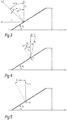
- a cam surface which is helical with constant pitch is characterized by the fact that its axial travel, that is to say its travel along the tilt axis defined above, varies proportionally with the angular travel of this surface, c is its race around the tilt axis.
- the helical surface makes a complete turn on itself around the tilting axis, in other words it achieves an angular travel of 360 °, a given point of this helical surface moves axially from a race worth the step of the surface.
- the effective path of this point which has the shape of a circular helix centered on the tilt axis, has a length which is dependent on the distance of this point from the axis of tilt: when this point is located at a distance from the tilt axis equal to the external radius, denoted rext, of the helical surface measured with respect to the tilt axis and this rext radius is constant over the entire range of the helical surface around the tilt axis, this point travels through a circular helix which forms the outer contour of the helical surface and which has a length of 2. ⁇ .rext and a helix angle denoted ⁇ rext ; but when this point is located at a distance from the tilt axis equal to the interior radius, denoted rint, of the helical surface measured relative to the tilt axis and this radius rint is constant over the entire extent of the helical surface around the tilt axis, this point travels through a circular helix which forms the inner
- the figure 1 thus illustrates the linear function linking the axial travel and the angular travel of the helical surface, according to the helix considered of this helical surface.
- the cam surface behaves generally as at an intermediate propeller of this cam surface, this intermediate propeller being situated between its inner periphery and its perimeter outside.
- WO 2007/075735 discloses a locking mechanism for reversibly locking a cycle wheel shaft on the frame of a cycle.
- This locking mechanism comprises a cam system comprising three pairs each associating a cam surface and a cam follower surface, which are respectively carried by parts of the mechanism, movable in rotation with respect to each other about an axis centered on the shaft of the impeller cycle.
- the cam surface of each of the three aforementioned pairs is generally helical, having a pitch which varies continuously around the axis over the entire functional extent of the cam surface, while the associated cam follower surface is present under the shape of a cylindrical lug which is pressed axially against the cam surface.
- the object of the present invention is therefore to improve the clamping devices of the type described so far, in particular with a view to their use on self-service cycles.
- the subject of the invention is a clamping device, in particular for clamping a saddle for a cycle, as defined in claim 1.
- the invention thus goes against the prejudice that, as soon as a helical cam surface is made of a material capable of creep and therefore lead to a gradual decrease over time in the intensity of the tightening produced by the device, only a congruent bearing interface between the cam surface and the cam follower surface is possible over the entire relative angular travel between these surfaces, which necessarily leads to the fact that the cam surface and the cam follower surface have constant pitches and of the same absolute value over their entire functional range.
- the invention allows that when tightening and loosening the device, the contact pressure between the or each cam surface cam and the cam follower surface is certainly high, but this high pressure occurs only for a very short period corresponding to the transient phases of passage of the lever between its open and closed positions, without risk of creep for the material constituting the cam surfaces.
- the axial clamping stroke is still small so that the axial force generated is still far from reaching the maximum obtained at the end of the stroke during clamping.
- the invention thus makes it possible to produce the cam surface or surfaces of its device in a thermoplastic material, which proves to be both economical, in particular in connection with the possibility of producing the cam surface or surfaces by injection, effective for limit the coefficient of friction, and resistant to wear, especially compared to metals.
- the propeller along which the helix angle varies in accordance with the invention, can be either produced in the form of a crest, or defined geometrically in relation with relation (2) given above.
- the invention provides, to vary the helix angle of this support propeller, to play either on a variation of the pitch of the or each cam surface, or on a variation of the radius of the propeller, or on a combination of the two aforementioned variations.
- a clamping device 1 is shown making it possible to clamp an element to be clamped 2, which is only shown on the figure 6 , and only partially and schematically, in dotted lines.
- the element to be clamped 2 can in particular be a tube of a frame of a cycle, in particular of a frame of a bicycle, inside which a seat post is received coaxially , not shown, itself surmounted by a saddle, also not shown.
- the reader may refer to the documents WO 2012/066215 and EP 2,927,517 to have additional details relating to such a frame tube receiving such a seatpost, it being recalled that these aspects are not limiting of the present invention.
- the clamping device 1 comprises a clamping collar 10 generally having an omega shape.
- the clamp 10 defines a central axis X10 around which the clamp extends by defining, inside the clamp, a free volume, generally cylindrical and centered on the axis X10: in service, the element to be clamped 2 is placed inside the aforementioned free volume so that the clamp surrounds in a substantially coaxial manner the element to be clamped 2, as shown diagrammatically on figure 6 .
- the clamp 10 is open at a point on its periphery: the clamp 10 thus has two ends 11 and 12 which are separated from one another, in a direction orthhoradial to the axis X10, by a slot 13.
- the slot 13 By playing on the opening-closing of the slot 13, in other words by spreading / bringing the ends 11 and 12 towards each other, by means of the deformation of the clamp 10, the latter more or less strongly encloses the element to be clamped 2, in particular with a view to blocking / unblocking the seatpost mentioned above or a similar member received inside the element to be clamped 2.
- the clamping device 1 comprises a lever 20 which controls the deformation of the clamping collar 10 by acting on the ends 11 and 12 of the latter. More specifically, the lever 20 is pivotally mounted on the ends 11 and 12 around a tilting axis Y20, which extends substantially perpendicular to the central axis X10 and offset with respect to this central axis, passing through the ends 11 and 12 of the clamp 10.
- the tilting axis Y20 extends in the orthoradial direction in which the ends 11 and 12 are separated by the slot 13.
- the lever 20 is intended to be actuated by a user by means of the tilting of this lever around the tilting axis Y20, and this in opposite directions in order to selectively tighten and loosen the clamping collar 10.
- the lever 20 is tilted from an open position, shown on the figures 11 to 13 , in a closed position, shown on the figures 6 to 8 and 14 to 18 .
- the angular travel, around the tilting axis Y20, of the lever 20 between these open and closed positions is not limitative of the invention, it being understood that it is typically less than 360 °, in particular less than 180 °, or even substantially equal to 90 ° in the context of using the clamping device 1 to tighten the saddle of a cycle.
- the angular travel of the lever 20 between these open and closed positions is considered to be equal to 90 °.
- the embodiment of the lever 20 is not limiting as long as this lever can be manipulated by hand by a user in order to tilt it around the tilting axis Y20.
- the geometry of the overall shape of this lever 20 is not limited to that shown in the figures, it being further noted that, for illustration reasons, the lever 20 is drawn as being split into two parts on the figures 6 to 8 , while it can be made in one piece, as clearly visible on the figures 11 , 12 and 14 .
- the lever 20 comprises two arms 21 and 22, which extend transversely to the tilting axis X20. These arms 20, 21 and 22 are arranged on either side, in the direction of the tilting axis Y20, of the clamp 10, being sufficiently distant from each other to allow the clamp 10 to pass between these arms 21 and 22 during the tilting of the lever between the open and closed positions. At their end opposite to the tilting axis Y20, the arms 21 and 22 meet to form a manual gripping area. Opposite this gripping zone, the arms 21 and 22 respectively have ends 23 and 24, which are both crossed by the tilting axis Y20 and between which the ends 11 and 12 of the clamp are interposed 10.
- the clamping device 1 further comprises a cam system 30 which mechanically connects the lever 20 to the ends 11 and 12 of the clamp 10 and which acts in translation, along the tilting axis Y20, on the ends 11 and 12 of the clamp in order to bring these ends one towards / away from one 'other, during the tilting of the lever 20 around the tilting axis Y20 between the open and closed positions of this lever.
- a cam system 30 which mechanically connects the lever 20 to the ends 11 and 12 of the clamp 10 and which acts in translation, along the tilting axis Y20, on the ends 11 and 12 of the clamp in order to bring these ends one towards / away from one 'other, during the tilting of the lever 20 around the tilting axis Y20 between the open and closed positions of this lever.
- the cam system 30 includes two cam parts 31 and 32, between which are interposed, along the tilting axis Y20, the ends 11 and 12 of the clamp 10, the cam piece 31 being axially interposed between the end 11 and the end 23 of the lever 20 while the cam piece 32 is axially interposed between the end 12 and the end 24 of the lever 20.
- Each of the cam pieces 31 and 32 is crossed by the tilting axis Y20 and delimits, on its face 31A, respectively 32A, facing the end 23 of the lever 20, respectively the end 24 of the lever 20, at least one cam surface 33, respectively 34.
- the face 31A, respectively 32A, of the cam part 31, respectively 32 includes two cam surfaces 33, respectively two cam surfaces 34, which succeed each other around the tilt axis Y20 and which will be presented in detail it further.
- the face 31A, respectively 32A, of the cam part 31, respectively 32 has a face 31B facing the end 11 of the clamp 10, respectively 32B facing the end 12 of the clamp 10.
- the faces 31B and 32B are respectively engaged with the ends 11 and 12 of the clamp 10, so as to link in rotation the cam pieces 31 and 32 and the ends 11 and 12 of the clamp, around the tilting axis Y20.
- a first solution consists in rigidly connecting the cam pieces 31 and 32 to, respectively, the ends 11 and 12 of the clamp 10, and this by any appropriate means, such as lugs, glue, etc.
- the cam parts have come in one piece with, respectively, the ends 11 and 12 of the clamping collar, which amounts to saying that, unlike the embodiment envisaged so far, the cam parts 31 and 32 are not separate from the collar clamping and that the cam surfaces 33 and 34 are delimited by material extensions of the ends 11 and 12 of the clamp.
- the face 31B, respectively 32B, of the cam piece 31, respectively 32 includes a cylindrical surface 35, respectively 36, which is centered on a pivot axis X35, respectively X36, which is both parallel to the central axis X10 of the clamp 10 and intersecting with the tilting axis Y20, as clearly visible on the figures 13 and 15 .
- the cylindrical surface 35, respectively 36 cooperates, by complementarity of shapes, with a cylindrical surface 15, respectively 16, delimited by the end 11, respectively 12, of the clamp 10, so that the cam piece 31, respectively 32, either linked in rotation about the tilting axis Y20 at the end 11, respectively 12, of the clamp 10 and be pressed along this tilting axis Y20 against this end 11, respectively 12, while allowing a clearance in pivoting about the pivot axis X35, respectively X36, between the cam piece 31 and the end 11, respectively between the cam piece 32 and the end 12.
- the cylindrical surfaces 35 and 36 are convex and the cylindrical surfaces 15 and 16 are concave, it being understood that, by way of variant not shown, the direction of the curvatures of these surfaces can be reversed.
- the pivoting clearance allows the cam pieces 31 and 32 to accommodate the change in inclination of the ends 11 and 12 of the clamp 10 with respect to the tilting axis Y20 during approximation / relative spacing. of these ends 11 and 12, without modifying the corresponding inclination of the cam parts 31 and 32, as clearly visible by comparison of the figures 13 and 15 .
- cam follower surfaces 25 and 26 which are linked in rotation, around the tilting axis Y20, to the lever 20 and which, in service, are supported, along the tilting axis Y20, against the cam surfaces 33 and 34 of the cam pieces 31 and 32. More specifically, in the embodiment considered in the figures, two cam follower surfaces 25 are provided on a face 23A of the end 23 of the lever 20, turned along the tilting axis Y20 towards the end 11 of the clamp 10, and two cam follower surfaces 26 are provided on a face 24A of the end 24 lever 20, facing towards the end 12 of the clamping collar.
- the two cam follower surfaces 25, respectively 26 are symmetrical with one another with respect to the tilting axis Y20 and each extend over approximately 90 ° around the tilt axis Y20, being separated from each other by two angular regions, diametrically opposite, of the face 23A, respectively 24A, set back, along the tilting axis Y20, of the cam follower surfaces 25, respectively 26.
- the cam follower surfaces 25, respectively 26 are projecting, along the tilting axis Y20, with respect to the aforementioned angular regions of the face 23A, respectively 24A.
- the main part 26.1 and the opposite edges 26.2 and 26.3 are also referenced for one of the cam follower surfaces 26 on the figure 7 .
- the clamping device 1 comprises a screw-nut connection system 40 making it possible to hold the cam surfaces 33 and 34 in abutment against the cam follower surfaces 25 and 26 in all the tilted positions of the lever 20 between its open positions and closed included.
- this screw-nut connection system 40 comprises a journal 41 and a nut 42, both centered on the pivot axis Y20.
- the pin 41 passes through the two ends 23 and 24 of the lever 20.
- the pin 41 is provided with a head 43, which emerges from the end 23 of the lever 20 and which is supported, along the tilting axis Y20 and in the direction of the end 11 of the clamp 10, against a face 23B of the end 23, opposite the face 23A of the latter.
- the pin 41 is provided with a thread 44 around which the nut 42 can be screwed while bearing, along the tilting axis Y20 and in the direction of the end 12 of the clamp 10, against a face 24B of the end 24 of the lever 20, opposite to the face 24A of this end 24.
- the two ends 23 and 24 of the lever 20, the two ends 11 and 12 of the clamp 10 and the cam system 30 are clamped, along the tilting axis Y20, between the head 43 and the nut 42, l 'intensity of this clamping being directly related to the extent of the screwing of the nut 42 on the thread 44.
- the arms 21 and 22 of the lever 20 have a sufficient length to allow the bending of these arms and therefore a reconciliation according to the tilting axis Y20 of the ends 23 and 24 necessary for adjusting the clamping device 1.
- the intensity of this clamping is preset during the installation and maintenance of the clamping device 1.
- the user of the clamping device 1 is not supposed to adjust the presetting of the screw-nut connection system 40.
- the screw-nut connection system 40 has advantageous optional arrangements, detailed below.
- the pin 41 is advantageously linked in rotation, about the tilting axis Y20, to the lever 20: in the embodiment considered in the figures, this connection in rotation is ensured by complementarity of shapes between a part with a square section 45 of the pin 41, located under the head 43, and a housing complementary to the end 23 of the lever 20, hollowed out in the face 23B of this end 23, as clearly visible on the figure 17 .
- the nut 42 is designed to be locked in rotation, about the tilting axis Y20, relative to the end 24 of the lever 20 in a plurality of indexed positions, distributed around the tilting axis Y20 : in this way, when the nut 42 occupies one of the aforementioned indexed positions, its unscrewing with respect to the pin 41 is prevented by blocking with respect to the end 24 of the lever 20, while allowing , for an installation or maintenance operator, to unlock the nut opposite the end 24 and thus to adjust the screwing of the nut 42 on the thread 44.
- the nut 42 has, on its axial side intended to be turned towards the end 24 of the lever 20, a bearing face 42A which, in service, is pressed axially against and cooperates in an indexed manner with the face 24B of the end 24 of the lever 20.
- the cooperation between the faces 42A and 24B, aimed at blocking the rotation of the nut 42 around the axis tilting Y20 relative to the end 24 of the lever 20, is produced by complementary shapes: thus, in the embodiment considered in the figures, the bearing face 42A of the nut 42 is provided with a plurality of concave spherical caps 46, which, as clearly visible on the figures 7 and 8 , are distributed around the tilting axis Y20, defining the aforementioned plurality of indexed positions, and which, in the assembled state of the clamping device 1, receive in a complementary manner one or more spherical caps 27 convex which, as clearly visible on the figures 6 and 18 , are provided projecting from the face 24B of the end 24 of the lever 20.
- a first approach consists in that the clamp 10 is provided resilient so that, even when the lever 20 is in the open position, the clamp exerts a stress, in the tilting axis Y20, which separates from one another the two ends 11 and 12 of the clamp 10.
- the collar is dimensioned to have sufficient elasticity so that its deformation remains elastic when the lever 20 is in the closed position.
- the clamp 10 is in particular made of a material having good elastic resistance, typically greater than 200 MPa, or even greater than 240 MPa.
- the clamp 10 can thus be made of aluminum, in particular loaded with silicon and magnesium, and be produced by spinning, the clamp being spun open and then machined in the constrained closed position, before being released after machining its bore. interior.
- a second approach which can be combined with the first approach, consists in providing that the element to be clamped 2 is split and opened in order to prestress the clamping collar 10 upon opening.
- the tube of the frame of this cycle, around which the clamping device 1 is intended to be installed can thus be provided opened by a longitudinal slot and then expanded. radially, for example using a conical mandrel, which, moreover, facilitates the sliding of the seatpost inside this tube.
- a third approach which can be combined with one and / or the other of the two aforementioned approaches, consists in interposing, along the tilting axis Y20, one or more springs between the screw-nut connection system 40 and the rest of the clamping device 1.
- springs, referenced 50 are thus attached, being interposed axially between the head 43 of the pin 41 and the end 23 of the lever 20, as well visible on figures 6 to 8 , 17 and 18 .
- these springs 50 can provide an axial force of the order of 20 N.
- the nut 42 has arrangements, in particular arrangements of shapes, aimed at ensuring that its rotation around the tilting axis Y20 preferably requires the use of a specific tool, for example a key provided with lugs arranged in a complementary manner to an imprint provided on a face 42B of the nut 42, opposite its face 42A.
- the rotation of the nut 42 by the operator must be carried out so as to overcome the resistance that the cooperation between the face 42A of this nut and the face 24B of the end 24 of the lever 20 opposes. It is understood that, in the case where the clamping device 1 is energized as explained above, the torque applied by the operator to the nut 42 must be high enough to counter the resilience of the clamp 10 and / or the resilience of the element to be clamped 2 and / or the resilience of the springs 50 or of similar added springs.
- the faces 42A and 24B cooperate with each other, in particular by complementarity of shapes, to lock the nut 42 relative to the lever 20 in a plurality of positions indexed around of the tilting axis Y20
- the faces 42A and 24B must be separated axially from one another to allow the passage of the nut between two of these indexed positions: in the case where the cooperation between the faces 42A and 24B is produced by the caps 46 and 27 described above, the tangency angle of these caps is advantageously provided for less than 45 ° so that the contact between the caps 46 and the caps 27 is reversible, so that when the operator exerts a torque on the nut, an axial force is generated directly by the caps to move the nut 42 away from the end 24 of the lever 20.
- the only application of a couple to the nut 42 by the operator may prove to be insufficient to allow the nut to rotate, the operator then having to carry out an additional manipulation aiming to axially separate the faces 42A and 24B from one another, if necessary using a specific tool.
- the angular indexing between the faces 42A and 24B allows the operator to quickly count and assess the number of indexing notches, necessary for presetting or re-adjusting the clamping device 1.
- the two cam surfaces 33 are symmetrical to one another with respect to the tilting axis Y20; moreover, with respect to a geometric plane, perpendicular to the tilting axis Y20 and containing the central axis X10, the cam surfaces 33 are symmetrical with the cam surfaces 34.
- this cam surface 33 is bordered by a projection 37 projecting from this angular end, in particular along the axis.
- Tipping Y20 the two cam surfaces 33 each extend 180 ° around the tilt axis, so that the surface portion 33.4 of each of the cam surfaces 33 opens, at its angular end opposite to the surface portion 33.2, on the projection 37 associated with the other cam surface, as clearly visible on the Figures 9 and 10 .
- the cam surface 25, associated with the cam surface 33 detailed above and thus forming with the latter a pair cam surface / cam surface is pressed on one of the surface portions 33.1 to 33.4 as a function of the tilted position of the lever 20 around the tilting axis Y20.
- the cam follower surface 25, more precisely the edge 25.2 of the latter is pressed, along the tilting axis Y20, against the surface portion 33.1: the contact between the edge 25.2 of the cam follower surface 25 and the surface portion 33.1 may, where appropriate, be limited to an area of almost point angular extent, while, at the same time, the opposite edge 25.3 of the surface cam follower 25 abuts, in a direction peripheral to the tilting axis Y20, against the projection 37 associated with the cam surface 33.
- the figure 19 makes it possible to clearly see the selective support of the cam follower surface 25 against the surface portions 33.1 to 33.4 and against the projection 37, as a function of the position of the lever 20: on this figure 19 , depending on the angular dimension of the cam surface 33, identified by the angles ⁇ 0 to ⁇ 4 defined above, the axial travel, that is to say the travel along the tilting axis Y20, of the workpiece cam 31 at its cam surface 33 is drawn, by associating it with three profiles, represented in dotted lines, of the cam follower surface 25: the leftmost profile on the figure 19 corresponds to the open position of the lever 20 and the rightmost profile corresponds to the closed position of this lever while the middle profile corresponds to an intermediate position of the lever between the open and closed positions.
- the angular travel of the lever 20 between the open and closed positions which corresponds to the angular difference between the leftmost profile and the rightmost profile, can thus be approximately 90 °, as mentioned above in the context of the use of the clamping device 1 to clamp the saddle of a cycle.
- the figure 19 also makes it possible to see that the surface portions 33.1 to 33.4 are not found, in the graph of this figure 19 , in the form of respective aligned slopes.
- the graph of the figure 19 has a steeper slope than at the surface portion 33.2, that is to say between the angular dimensions ⁇ 0 + ⁇ 1 + ⁇ 3 and ⁇ 0 + ⁇ 1 + ⁇ 3 + ⁇ 2.
- the pitch of the cam surface 33 is greater on the surface portion 33.1 than on the surface portion 33.2, it being noted that the advantage of this arrangement will appear a little further.
- the surface portion 33.3 may have a smaller angular extent than that in the example of the figures, or even have a quasi-punctual extent, as long as this surface portion 33.3 materially ensures the transition, if necessary geometrically discontinuous, between the surface portions 33.1 and 33.2.
- the pitch of the surface portion 33.2 is provided substantially equal to the pitch of the main part 25.1 of the cam surface 25.
- the respective pitches of the surface portion 33.2 and of the main part 25.1 of the cam surface 25 are equal, except for one functional clearance.
- the surface portion 33.2 can advantageously be provided congruent with the cam follower surface 25: in this way, when the lever 20 is in the closed position, the contact interface between the cam surface 33 and the contact surface.
- cam follower 25 is very wide, in corresponding substantially to the entire surface portion 33.2, which distributes on the latter the support stresses between the cam surface 33 and the cam follower surface 25.
- the creep of the material constituting the cam surface 33 is thus avoided , which advantageously makes it possible to envisage manufacturing the cam surface 33 with a material sensitive to creep, in particular a thermoplastic material, such as polyacetal or PBT (poly (butylene terephthalate)).
- a material sensitive to creep in particular a thermoplastic material, such as polyacetal or PBT (poly (butylene terephthalate)
- PBT poly (butylene terephthalate)
- the fact that there is no congruence between the surface portions 33.1 and 33.3 and the cam follower surface 25 implies that, when the lever 20 passes between the open and closed positions, the pressing the cam surface 25 against the surface portions 33.1 and 33.3 induces a high contact pressure: however, this does not cause the material constituting the cam surface 33 to creep because this contact pressure is not established that for a very short period of time, during the transition between the open and closed positions.
- the contact interface between the cam surface and the cam surface continues to grow. to reach a maximum at the end of tightening while, at the same time, the tightening force increases almost linearly to its maximum in the closed position.
- the figure 19 furthermore makes it possible to understand that the surface portion 33.0 of the cam surface 33 has no functional interest, in the sense that this surface portion 33.0 does not have to establish pressing contact with the surface of cam follower 25.
- the cam follower surface 25 cooperates in abutment with the surface portion 33.1 and the projection 37, as explained above, while being able to remain at a distance from the portion surface 33.0, in particular by providing sufficient play between them, as illustrated in the figure 19 .
- the surface portion 33.0 can have a lesser extent, or even zero, by means of an increased extent for the surface portion 33.1.
- this cam surface 33 is curved so as to form a crest 33A which, as clearly visible on the Figures 9 and 10 , wraps around the tilt axis Y20, extending at least over the surface portions 33.1 and 33.2 of the cam surface 33.
- the crest 33A extends from way continues on the surface portions 33.1, 33.2 and 33.3, extending even on the surface portions 33.0 and 33.4. This being the case, as a variant not shown, the crest 33A may extend discontinuously over these surface portions, if necessary running only over a part only of one or more of these surface portions.
- the crest 33A corresponds, in any cutting plane containing the tilting axis Y20, to the most salient point of the cam surface 33, in other words at the top of the curved profile of the cam surface .
- this curved profile of the cam surface 33 has a very large radius of curvature. In service, that is to say when the cam follower surface 25 is pressed against the cam surface 33, the corresponding bearing stresses are concentrated at the crest 33A.
- This concentration of the stresses at the level of the crest 33A can be used to improve the behavior of the cam system 30.
- the radius, that is to say -to say the distance radially to the tilting axis Y20, from the crest 33A is not constant around this axis, but varies according to the angular dimension of the cam surface 33, as clearly visible on the Figures 9 and 10 and as illustrated on the figure 20 which shows this evolution of the radius of the crest 33A.
- the radius of the crest 33A is smaller on the surface portion 33.1 of the cam surface 33, that is to say between the angular dimensions ⁇ 0 and ⁇ 0 + ⁇ 1, than on the surface portion 33.2, c '' i.e. between the angular dimensions ⁇ 0 + ⁇ 1 + ⁇ 3 and ⁇ 0 + ⁇ 1 + ⁇ 3 + ⁇ 2.
- the difference in radius between the surface portions 33.1 and 33.2 is accommodated by the surface portion 33.3, on which the crest sees its radius varying continuously to make the transition between the surface portions 33.1 and 33.2.
- the radius of the crest 33A may not be strictly constant, but may, as in the example shown in the figures, vary, it being noted that, for reasons which will appear a little further on, the value of the radius is advantageously minimum in the region of the surface portion 33.1, opposite the surface portion 33.2, and the value of the radius is advantageously maximum in the region of the surface portion 33.2, opposite to the surface portion 33.1.
- the crest 33A has a helix angle ⁇ 33A which, without changing sign, evolves so important as a function of the angular dimension of the cam surface 33, it being recalled that this helix angle, which is measured relative to a plane perpendicular to the tilting axis Y20, responds to the relation (1) given in the introduction.
- the figure 21 allows to visualize this variation of the helix angle ⁇ 33A ⁇
- the helix angle ⁇ 33A which is positive over the entire functional range of the cam surface 33, is greater over the portion of surface 33.1, i.e. between the angular dimensions ⁇ 0 and ⁇ 0 + ⁇ 1, than on the surface portion 33.2, i.e. between the angular dimensions ⁇ 0 + ⁇ 1 + ⁇ 3 and ⁇ 0 + ⁇ 1 + ⁇ 3 + ⁇ 2.
- the value of the helix angle ⁇ 33A may not be constant, but may vary, as shown on the figure 21 : advantageously, on the surface portion 33.1, the helix angle ⁇ 33A is maximum in the region of the latter opposite to the surface portion 33.2; on the surface portion 33.2, the helix angle ⁇ 33A is minimal in the region of the latter opposite to the surface portion 33.1. Between the surface portions 33.1 and 33.3, the surface portion 33.2 accommodates the variation of the helix angle ⁇ 33A ⁇
- the value of the helix angle ⁇ 33A on the surface portion 33.1 and the value of the helix angle ⁇ 33A on the surface portion 33.2 are provided respectively greater and less than an angle region, which is hatched on the figure 21 and on either side of which the support between the cam surface 33 and the cam follower surface 25 does not exhibit the same stability, in the sense that, above this region, this behavior is unstable, in other words reversible, while below this region, this behavior is stable, in other words irreversible.
- the helix angle ⁇ 33A is advantageously provided greater than 13 °, or even 14 ° over the entire surface portion 33.1, and provided less than 6 °, or even 5 ° on the entire surface portion 33.2.
- the change in the value of the helix angle ⁇ 33A is also beneficial for the tightening efficiency by the cam surface 33, as illustrated by the figure 22 , it being recalled that the tightening efficiency was defined previously by equation (5).
- the figure 22 shows that when passing the lever 20 from the open position to the closed position, the clamping efficiency is very good, compared to that when the lever is in the closed position. It is indeed in this transient phase that the high pitch of the surface portion 33.1 makes it possible to notably increase the tightening stroke, without increasing the maximum tightening torque as mentioned below.
- the figure 23 which shows the evolution of the tightening torque, in connection with the relation (4) given above, as a function of the angular position of the lever identified by the angular dimensions ⁇ 0, ⁇ 1, ⁇ 2, ⁇ 3 and ⁇ 4 detailed above, allows to observe that the force to be applied by the user is significant only during the initiation of the tightening, that is to say when the lever 20 leaves its open position towards its closed position, while then increasing so much lower, until reaching a maximum value.
- the aforementioned maximum value is less than the effort that the user must produce to reach the closed position.
- the figure 23 also makes it possible to observe that, beyond the closed position, the cam surface 33 induces a sudden increase in the tightening torque, which is linked to the presence of the surface portion 33.4: thanks to this surface portion 33.4 , the user clearly feels that he has tilted the lever 20 to the closed position, without it being necessary to tilt the lever further.
- the figure 24 illustrates the evolution of the loosening torque, in connection with the relation (7) which was given above.
- the figure 24 makes it possible to observe that the torque to be applied by the user, which is negative when the lever 20 leaves its closed position towards its open position, becomes positive when the lever is close to reaching its open position: in other words, as soon as the user has moved the lever 20 sufficiently from its closed position to its open position, the lever switches automatically reversibly to its open position, which gives a frank indication to the user that this open position is thus reached.
- the cam surface 33 makes it possible to have greater stability at the start of the loosening, in the sense that at the start of the loosening, the loosening torque to be applied to the cam surface 33 is much more negative than that for a helical cam surface with constant pitch and with inner and outer edges with constant respective radii.
- varying the helix angle ⁇ 33A of the crest 33A presents substantial and numerous advantages for the clamping device 1.
- the variation in the helix angle ⁇ 33A is linked, partly, to the variation of the pitch between the surface portions 33.1 and 33.2 and, for another part, to the variation of the radius of the crest 33A, and this in connection with the relation (1) given above.
- a variant consists in that each cam surface is of constant pitch, but provided with a crest with variable radius, such as the crest 33A for the cam surfaces 33.
- Another variant consists in that each cam surface is provided with a ridge having a constant radius, while presenting a variable pitch between its portions corresponding to the surface portions 33.1 and 33.2 as described in the figures.
- this geometric helix is functionally similar to the crest 33A envisaged for the example considered in the figures, in the sense that both the crest 33A and this geometric helix in the absence of a crest constitute a propeller, which wraps around the tilting axis Y20, extending at least partially over the surface portions 33.1 and 33.2 of the cam surface 33, and at which the bearing stresses between the cam surface 33 and the associated cam follower surface 25.
- each cam surface is devoid of a crest but defines the aforementioned geometric helix
- the variation the helix angle of this geometric helix results either from the variation of the pitch between the surface portions 33.1 and 33.2 of the cam surface, or from an appropriate variation of the outside radius and / or the inside radius of the surface cam, either from the combination of these two provisions respectively relating to the pitch and to the interior and exterior radii of the cam surface.
Description
La présente invention concerne un dispositif de serrage. Elle concerne en particulier, mais de manière non exclusive, un tel dispositif pour serrer la selle d'un cycle.The present invention relates to a clamping device. It relates in particular, but not exclusively, to such a device for tightening the saddle of a cycle.
Les cycles, notamment les bicyclettes, sont pourvus d'une selle que l'utilisateur souhaite généralement pouvoir régler en hauteur pour des raisons évidentes de confort et de praticité. La selle est portée au sommet d'une tige de selle, qui est elle-même reçue coulissante dans un tube ad hoc du cadre du cycle : une fois que la hauteur de la selle par rapport au cadre est réglée, c'est-à-dire une fois que la tige de selle est coulissée dans le tube précité jusqu'à une position souhaitée le long de ce tube, la tige de selle doit être immobilisée par rapport au tube. Pour ce faire, il est connu d'utiliser un dispositif de serrage, qui est actionné manuellement par l'utilisateur et qui serre le tube sur la tige de selle pour l'immobiliser.Cycles, especially bicycles, are provided with a saddle that the user generally wishes to be able to adjust in height for obvious reasons of comfort and practicality. The saddle is carried on top of a seatpost, which is itself received sliding in an ad hoc tube of the cycle frame: once the height of the saddle relative to the frame is adjusted, i.e. -to say once the seat post is slid in the aforementioned tube to a desired position along this tube, the seat post must be immobilized relative to the tube. To do this, it is known to use a clamping device, which is actuated manually by the user and which clamps the tube on the seatpost to immobilize it.
L'invention s'intéresse aux dispositifs de serrage comprenant, d'une part, un collier de serrage, qui entoure coaxialement le tube précité et qui est ouvert de manière à présenter deux extrémités qui, par déformation du collier de serrage, se rapprochent l'une de l'autre afin d'enserrer le tube, et, d'autre part, un levier, qui est monté basculant sur les extrémités du collier de serrage autour d'un axe de basculement perpendiculaire à un axe central du collier de serrage.
- à pas constant, c'est-à-dire que ces surfaces s'enroulent autour de l'axe de basculement avec un pas qui ne varie pas autour de cet axe, et
- prévues chacune avec des rayons, respectivement intérieur et extérieur, qui sont constants, c'est-à-dire qui ne varient pas autour de l'axe de basculement.
- with constant pitch, that is to say that these surfaces are wound around the tilting axis with a pitch which does not vary around this axis, and
- each provided with radii, respectively interior and exterior, which are constant, that is to say which do not vary around the tilt axis.
Cette solution n'est pas satisfaisante, pour les raisons expliquées ci-après en regard des
Une surface de came qui est hélicoïdale à pas constant se caractérise par le fait que sa course axiale, c'est-à-dire sa course selon l'axe de basculement défini plus haut, varie proportionnellement avec la course angulaire de cette surface, c'est-à-dire sa course autour de l'axe de basculement. Cela revient à dire que la course axiale et la course angulaire de cette surface de came hélicoïdale sont liées par une fonction linéaire. Bien entendu, dès lors que la surface hélicoïdale fait un tour complet sur elle-même autour de l'axe de basculement, autrement dit qu'elle réalise une course angulaire de 360°, un point donné de cette surface hélicoïdale se déplace axialement d'une course valant le pas de la surface. Ceci étant, le trajet effectif de ce point, qui a la forme d'une hélice circulaire centrée sur l'axe de basculement, présente une longueur qui est dépendante de l'éloignement de ce point vis-à-vis de l'axe de basculement : lorsque ce point est situé à une distance de l'axe de basculement valant le rayon extérieur, noté rext, de la surface hélicoïdale mesuré par rapport à l'axe de basculement et que ce rayon rext est constant sur toute l'étendue de la surface hélicoïdale autour de l'axe de basculement, ce point parcourt une hélice circulaire qui forme le contour extérieur de la surface hélicoïdale et qui présente une longueur de 2.π.rext et un angle d'hélice noté βrext ; mais lorsque ce point est situé à une distance de l'axe de basculement valant le rayon intérieur, noté rint, de la surface hélicoïdale mesuré par rapport à l'axe de basculement et que ce rayon rint est constant sur toute l'étendue de la surface hélicoïdale autour de l'axe de basculement, ce point parcourt une hélice circulaire qui forme le pourtour intérieur de la surface hélicoïdale et qui présente une longueur de 2.π.rint et un angle d'hélice noté βrint. La ![]()
![]()
La fonction arc tangente (arctan) étant strictement croissante, on comprend que, sur la base de cette relation (1), l'angle d'hélice βr augmente avec le pas p et décroît avec le rayon r, l'angle d'hélice et le rayon étant indépendants l'un de l'autre.The tangent arc function (arctan) being strictly increasing, we understand that, on the basis of this relation (1), the helix angle β r increases with the step p and decreases with the radius r, the angle d helix and radius being independent of each other.
Par ailleurs, le phénomène de frottement entre deux pièces, notamment entre une surface de came et une surface de contre-came hélicoïdales, fait qu'il n'y a pas de glissement si la force résultante est comprise dans un cône dit de frottement, qui correspond à un cône de révolution, qui a pour axe la normale au contact entre la surface de came et la surface de contre-came et dont le demi-angle au sommet a pour valeur ϕ correspondant à l'arc tangente du coefficient de frottement du couple de matériaux composant respectivement la surface de came et la surface de contre-came. Si l'angle de la force résultante est à l'extérieur ou à l'intérieur du cône de frottement, les pièces commencent à glisser entre elles ou non. La
- sur le pourtour intérieur, on constate que la composante axiale de l'effort, notée R1X n'entre pas dans le cône de frottement hachuré sur la
figure 2 , ce qui est lié au fait que l'angle d'hélice βrint, est supérieur à ϕ ; la transmission de l'effort génère alors une composante tangente R1T provoquant le glissement entre elles de la surface de came et de la surface de contre-came ; la coopération entre la surface de came et la surface de contre-came, au niveau d'un petit rayon, est donc instable et réversible, de sorte qu'une poussée axiale entraîne une rotation entre la surface de came et la surface de contre-came ; - sur le pourtour extérieur, on constate que la composante axiale de l'effort, notée R2X, est située à l'intérieur du cône de frottement hachuré sur la
figure 2 , ce qui est lié au fait que l'angle d'hélice βrext est inférieur à ϕ ; ainsi, la transmission de l'effort n'engendre aucun glissement entre la surface de came et la surface de contre-came ; la coopération entre la surface de came et la surface de contre-came au niveau d'un grand rayon est donc stable et irréversible, si bien qu'une poussée axiale n'entraîne pas une rotation entre la surface de came et la surface de contre-came.
- on the inner periphery, it can be seen that the axial component of the force, denoted R 1X, does not enter the hatched friction cone on the
figure 2 , which is linked to the fact that the helix angle β rint , is greater than ϕ; the transmission of the force then generates a tangent component R 1T causing the cam surface and the cam follower surface to slide between them; the cooperation between the cam surface and the cam follower surface, at a small radius, is therefore unstable and reversible, so that an axial thrust causes a rotation between the cam surface and the counter cam surface cam; - on the outer periphery, it can be seen that the axial component of the force, denoted R 2X , is located inside the hatched friction cone on the
figure 2 , which is linked to the fact that the helix angle β rext is less than ϕ; thus, the transmission of the force does not cause any sliding between the cam surface and the cam follower surface; the cooperation between the cam surface and the cam follower surface at a large radius is therefore stable and irreversible, so that an axial thrust does not cause a rotation between the cam surface and the counter surface -cam.
En pratique, pour caractériser le fonctionnement d'un tel système, on peut considérer que la surface de came se comporte globalement comme au niveau d'une hélice intermédiaire de cette surface de came, cette hélice intermédiaire étant située entre son pourtour intérieur et son pourtour extérieur. Lorsque la pression exercée au travers de la surface de came est constante, on démontre que le rayon de l'hélice intermédiaire, que l'on peut qualifier de rayon équivalent, noté req, se détermine par la relation suivante : ![]()
![]()
On comprend donc qu'une surface de came hélicoïdale, à pas constant et avec pourtours intérieur et extérieur à rayons respectifs constants, présente une comportement assez incertain, dans le sens où il n'est pas certain que la pression de contact au travers de cette surface de came sera effectivement constante et appliquée sur l'hélice intermédiaire associée au rayon calculé selon la relation (2), étant souligné que l'usure et les tolérances de fabrication, entre autres, impactent la situation.It is therefore understood that a helical cam surface, with constant pitch and with inner and outer edges with constant respective radii, exhibits a behavior quite uncertain, in the sense that it is not certain that the contact pressure through this cam surface will be effectively constant and applied to the intermediate propeller associated with the radius calculated according to relation (2), it being emphasized that l wear and manufacturing tolerances, among others, impact the situation.
Il en résulte dans le dispositif de
Pour contourner la problématique de stabilité décrite jusqu'ici, on pourrait imaginer de réduire la valeur du pas de la ou des surfaces de came utilisées dans les dispositifs de
- même avec le levier en position ouverte, une contrainte de serrage substantielle risque d'être appliquée par le collier de serrage autour du tube, si bien qu'il est difficile pour l'utilisateur de lever ou descendre la tige de selle, que l'intérieur du tube raye la tige de selle en endommageant l'anodisation ou la peinture de cette tige, et qu'il y a même un risque de grippage et/ou d'usure de la tige de selle dans le tube ; et
- même avec le levier en position fermée, le dispositif risque de ne pas assez serrer le tube, le poids de l'utilisateur pouvant être suffisant pour entraîner la tige de selle à l'intérieur du tube malgré le serrage de ce dernier si bien qu'en service, la selle descend ou pivote, ce qui en use la tige et ce qui est particulièrement inconfortable pour le cycliste.
- even with the lever in the open position, substantial clamping stress may be applied by the clamp around the tube, making it difficult for the user to raise or lower the seatpost, which the the inside of the tube scratches the seatpost, damaging the anodization or the painting of the seatpost, and that there is even a risk of seizing and / or wear of the seatpost in the tube; and
- even with the lever in the closed position, the device may not tighten the tube enough, the user weight being sufficient to drive the seatpost inside the tube despite the tightening of the latter so that in use, the saddle descends or pivots, which wears out the rod and which is particularly uncomfortable for the cyclist.
Aux considérations techniques qui précèdent, s'ajoute un autre aspect critique pour ce type de dispositif de serrage, à savoir, d'une part, son comportement dynamique, à savoir en serrage et en desserrage c'est-à-dire lorsque le levier passe, respectivement, de sa position ouverte à sa position fermée et de sa position fermée à sa position ouverte, et, d'autre part, son comportement statique.In addition to the above technical considerations, there is another critical aspect for this type of clamping device, namely, on the one hand, its dynamic behavior, namely in clamping and in loosening, that is to say when the lever passes, respectively, from its open position to its closed position and from its closed position to its open position, and, on the other hand, its static behavior.
Le fonctionnement en serrage d'une surface de came hélicoïdale à pas constant et avec pourtours intérieur et extérieur à rayons respectifs constants est illustré par la
- une composante d'effort axiale FX selon l'axe de basculement précité, et
- une composante d'effort tangente FT orthoradiale à l'axe de basculement.
- an axial force component F X along the aforementioned tilting axis, and
- a component of force tangent F T orthoradial to the tilting axis.
En tenant compte de ϕ défini plus haut, l'angle d'hélice βr et le rayon r d'une hélice donnée de la surface de came, hélice où est appliqué l'effort F, sont liés par les relations : ![]()
![]()
![]()
![]()
![]()
![]()
C étant le couple que doit produire l'utilisateur pour générer l'effort de serrage et η étant le rendement, en pourcents, du serrage correspondant.C being the torque that the user must produce to generate the tightening force and η being the yield, in percent, of the corresponding tightening.
Le fonctionnement en desserrage de cette surface de came hélicoïdale à pas constant et avec pourtours intérieur et extérieur à rayons respectifs constants est illustré par la ![]()
![]()
![]()
![]()
C étant le couple que doit produire l'utilisateur pour générer l'effort de desserrage F.C being the torque that the user must produce to generate the loosening force F.
Le fonctionnement en statique de la surface de came hélicoïdale à pas constant et avec pourtours intérieur et extérieur à rayons respectifs constants est illustré par la
Les diverses considérations qui précèdent illustrent la complexité de concevoir un dispositif de serrage du type évoqué plus haut, en particulier lorsque ce dispositif est destiné à être utilisé dans un cadre particulièrement exigeant, notamment celui des cycles en libre-service. En effet, la hauteur de selle d'un cycle en libre-service doit pouvoir être réglée de manière simple et intuitive, en ne nécessitant que peu d'effort de la part de l'utilisateur, tout en garantissant un blocage efficace, et ce de manière pérenne, c'est-à-dire en résistant à la fois à un usage intensif, de par exemple plusieurs dizaines de réglages par jour, et à une exposition aux intempéries et au vandalisme.The various considerations which precede illustrate the complexity of designing a clamping device of the type mentioned above, in particular when this device is intended to be used in a particularly demanding environment, in particular that of self-service cycles. Indeed, the saddle height of a self-service cycle must be able to be adjusted in a simple and intuitive manner, requiring only little effort on the part of the user, while guaranteeing effective locking, and this perennially, that is to say by resisting both intensive use, for example several dozen settings per day, and exposure to weather and vandalism.
De son côté,
Le but de la présente invention est donc d'améliorer les dispositifs de serrage du type décrit jusqu'ici, notamment en vue de leur utilisation sur des cycles en libre-service.The object of the present invention is therefore to improve the clamping devices of the type described so far, in particular with a view to their use on self-service cycles.
A cet effet, l'invention a pour objet un dispositif de serrage, notamment de serrage d'une selle pour un cycle, tel que défini à la revendication 1.To this end, the subject of the invention is a clamping device, in particular for clamping a saddle for a cycle, as defined in
Grâce à la variation de l'angle d'hélice de l'hélice d'appui définie par la ou chaque surface de came du dispositif de serrage, l'invention permet que :
- lorsque le levier est en position fermée, la coopération entre la ou chaque surface de came et la surface de contre-came associée est stable, tout en produisant une composante d'effort axiale importante,
- lorsque le levier est en position ouverte, la coopération entre la ou chaque surface de came et la surface de contre-came associée est réversible, ce qui maintient le levier en position ouverte malgré l'effet du poids propre du levier tendant à le faire basculer vers la position fermée, et
- lorsque le levier est basculé de sa position ouverte à sa position fermée par entraînement de l'utilisateur, ce dernier n'a à appliquer qu'un couple limité grâce à un bon rendement local de la surface de came.
- when the lever is in the closed position, the cooperation between the or each cam surface and the associated cam follower surface is stable, while producing a significant axial force component,
- when the lever is in the open position, the cooperation between the or each cam surface and the associated cam follower surface is reversible, which keeps the lever in the open position despite the effect of the self-weight of the lever tending to tilt it towards the closed position, and
- when the lever is tilted from its open position to its closed position by driving the user, the latter only has to apply a limited torque thanks to good local efficiency of the cam surface.
Par ailleurs, on notera que l'invention va ainsi à l'encontre du préjugé selon lequel, dès lors qu'une surface de came hélicoïdale est réalisée dans un matériau susceptible de fluer et donc de conduire à une diminution progressive dans le temps de l'intensité du serrage produit par le dispositif, seule une interface d'appui congruente entre la surface de came et la surface de contre-came est envisageable sur toute la course angulaire relative entre ces surfaces, ce qui conduit nécessairement à ce que la surface de came et la surface de contre-came aient des pas constants et de même valeur absolue sur toute leur étendue fonctionnelle. Grâce à la variation de l'angle d'hélice de l'hélice d'appui de la ou chaque surface de came, l'invention permet que lors du serrage et du desserrage du dispositif, la pression de contact entre la ou chaque surface de came et la surface de contre-came est certes élevée, mais cette pression élevée ne survient que pendant une durée très courte correspondant aux phases transitoires de passage du levier entre ses positions ouverte et fermée, sans risque de fluage pour la matière constituant la ou les surfaces de came. En outre, lors de ces phases transitoires, la course de serrage axiale est encore faible de sorte que l'effort axial généré est encore loin d'atteindre le maximum obtenu en fin de course lors du serrage. Lorsque le levier passe de la position ouverte à la position fermée, l'effort axial ne commence à croître rapidement que lorsque la phase transitoire précitée se termine et que le levier atteint la position fermée : les pas respectifs de la surface de came et de la surface de contre-came deviennent alors identiques de sorte que l'interface commune ne va cesser de croitre jusqu'au serrage final pour limiter la pression de contact générée par l'effort axial croissant induit par le serrage. Cette caractéristique de croissance de l'interface de contact est nouvelle et même contraire par rapport à l'art antérieur, notamment par rapport aux documents d'art antérieur évoqués plus haut, dans le sens où dans
Lorsque le levier est en position fermée, le fluage est évité en prévoyant que la portion de la surface de came et la portion de la surface de contre-came, qui sont alors appuyées l'une contre l'autre, sont hélicoïdales et de même pas, ce qui permet de répartir sur une grande interface d'appui l'importante composante d'effort axial produite par la coopération entre la ou chaque surface de came et la surface de contre-came associée. L'invention permet ainsi de réaliser la ou les surfaces de came de son dispositif en une matière thermoplastique, ce qui s'avère à la fois économique, notamment en lien avec la possibilité de produire la ou les surfaces de came par injection, performant pour limiter le coefficient de frottement, et résistant à l'usure, notamment comparativement à des métaux.When the lever is in the closed position, creep is avoided by providing that the portion of the cam surface and the portion of the cam follower surface, which are then pressed against each other, are helical and likewise not, which makes it possible to distribute over a large support interface the large component of axial force produced by the cooperation between the or each cam surface and the associated cam follower surface. The invention thus makes it possible to produce the cam surface or surfaces of its device in a thermoplastic material, which proves to be both economical, in particular in connection with the possibility of producing the cam surface or surfaces by injection, effective for limit the coefficient of friction, and resistant to wear, especially compared to metals.
En pratique, comme expliqué plus en détail par la suite, l'hélice d'appui, le long de laquelle l'angle d'hélice varie conformément à l'invention, peut être soit réalisée sous forme d'une crête, soit définie géométriquement en lien avec la relation (2) donnée plus haut. Egalement comme expliqué plus en détail par la suite, l'invention prévoit, pour faire varier l'angle d'hélice de cette hélice d'appui, de jouer soit sur une variation du pas de la ou chaque surface de came, soit sur une variation du rayon de l'hélice d'appui, soit sur une combinaison des deux variations précitées.In practice, as explained in more detail below, the propeller, along which the helix angle varies in accordance with the invention, can be either produced in the form of a crest, or defined geometrically in relation with relation (2) given above. Also as explained in more detail below, the invention provides, to vary the helix angle of this support propeller, to play either on a variation of the pitch of the or each cam surface, or on a variation of the radius of the propeller, or on a combination of the two aforementioned variations.
Des caractéristiques additionnelles avantageuses du dispositif de serrage conforme à l'invention sont spécifiées aux revendications dépendantes.Additional advantageous features of the clamping device according to the invention are specified in the dependent claims.
L'invention sera mieux comprise à la lecture de la description qui va suivre, donnée uniquement à titre d'exemple et faite en se référant aux dessins sur lesquels :
- les
figures 1 à 5 sont des graphes schématiques qui ont été décrits précédemment, en lien avec une surface de came hélicoïdale à pas constant, - les
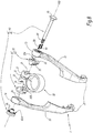
figures 6 à 8 sont des perspectives, sous des angles de vue respectifs qui sont différents, d'un éclaté d'un dispositif de serrage conforme à l'invention, un levier de ce dispositif étant en position fermée ; - la
figure 9 est une vue en perspective d'une pièce de came, montrée seule, appartenant au dispositif de serrage desfigures 6 à 8 ; - la
figure 10 est une vue en élévation selon la flèche X de lafigure 9 ; - la
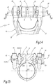
figure 11 est une vue en perspective du dispositif de serrage desfigures 6 à 8 , montré à l'état assemblé et alors que le levier de ce dispositif est en position ouverte ; - la
figure 12 est une vue en élévation selon la flèche XII de lafigure 11 ; - la
figure 13 est une coupe selon la ligne XIII-XIII de lafigure 12 ; - la
figure 14 est une vue similaire à lafigure 12 , illustrant le dispositif de serrage avec son levier en position fermée ; - les
figures 15 et16 sont des coupes selon respectivement les lignes XV-XV et XVI-XVI de lafigure 14 ; - la
figure 17 est une coupe selon la ligne XVII-XVII de lafigure 16 , - la
figure 18 est une coupe selon la ligne XVIII-XVIII de lafigure 17 , - la
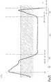
figure 19 est un graphe schématique montrant l'évolution de la course axiale de la pièce de came desfigures 9 et 10 en fonction d'une dimension angulaire d'une surface de came de cette pièce de came, - la
figure 20 est un graphe schématique montrant l'évolution du rayon d'une crête de la surface de came précitée en fonction de la dimension angulaire de cette dernière, - la
figure 21 est un graphe schématique montrant l'évolution de l'angle d'hélice de la crête précitée en fonction de la dimension angulaire de la surface de came précitée, - la
figure 22 est un graphe schématique montrant l'évolution du rendement du serrage par la surface de came précitée en fonction de la dimension angulaire de cette dernière, - la
figure 23 est un graphe schématique montrant l'évolution du couple à appliquer au levier du dispositif desfigures 6 à 8 pour serrer ce dispositif, et - la
figure 24 est une vue similaire à lafigure 23 , montrant l'évolution du couple pour desserrer le dispositif.
- the
Figures 1 to 5 are schematic graphs which have been described previously, in connection with a helical cam surface with constant pitch, - the
figures 6 to 8 are perspectives, from respective angles which are different, of an exploded view of a clamping device according to the invention, a lever of this device being in the closed position; - the
figure 9 is a perspective view of a cam part, shown alone, belonging to the device for tightening thefigures 6 to 8 ; - the
figure 10 is an elevation view along arrow X of thefigure 9 ; - the
figure 11 is a perspective view of the clamping devicefigures 6 to 8 , shown in the assembled state and while the lever of this device is in the open position; - the
figure 12 is an elevation view according to arrow XII of thefigure 11 ; - the
figure 13 is a section along line XIII-XIII of thefigure 12 ; - the
figure 14 is a view similar to thefigure 12 , illustrating the clamping device with its lever in the closed position; - the
figures 15 and16 are sections along lines XV-XV and XVI-XVI respectively of thefigure 14 ; - the
figure 17 is a section along line XVII-XVII of thefigure 16 , - the
figure 18 is a section along line XVIII-XVIII of thefigure 17 , - the
figure 19 is a schematic graph showing the evolution of the axial travel of the cam part of theFigures 9 and 10 as a function of an angular dimension of a cam surface of this cam part, - the
figure 20 is a schematic graph showing the evolution of the radius of a crest of the above-mentioned cam surface as a function of the angular dimension of the latter, - the
figure 21 is a schematic graph showing the evolution of the helix angle of the above-mentioned crest as a function of the angular dimension of the above-mentioned cam surface, - the
figure 22 is a schematic graph showing the evolution of the tightening efficiency by the aforementioned cam surface as a function of the angular dimension of the latter, - the
figure 23 is a schematic graph showing the evolution of the torque to be applied to the lever of the devicefigures 6 to 8 to tighten this device, and - the
figure 24 is a view similar to thefigure 23 , showing the evolution of the torque to loosen the device.
Sur les
Comme représenté sur les
Le collier de serrage 10 est ouvert en un point de sa périphérie : le collier de serrage 10 présente ainsi deux extrémités 11 et 12 qui sont séparées l'une de l'autre, dans une direction orthoradiale à l'axe X10, par une fente 13. En jouant sur l'ouverture-fermeture de la fente 13, autrement dit en écartant/rapprochant les extrémités 11 et 12 l'une vis-à-vis de l'autre, moyennant la déformation du collier de serrage 10, ce dernier enserre de manière plus ou moins forte l'élément à serrer 2, notamment en vue de bloquer/débloquer la tige de selle évoquée plus haut ou un organe similaire reçu à l'intérieur de l'élément à serrer 2.The
Egalement comme bien visible sur les
En service, le levier 20 est prévu pour être actionné par un utilisateur moyennant le basculement de ce levier autour de l'axe de basculement Y20, et ce dans des sens opposés pour, sélectivement, serrer et desserrer le collier de serrage 10. Ainsi, pour serrer le collier de serrage 10, le levier 20 est basculé d'une position ouverte, montrée sur les
La forme de réalisation du levier 20 n'est pas limitative du moment que ce levier puisse être manipulé à la main par un utilisateur en vue de le basculer autour de l'axe de basculement Y20. En particulier, la géométrie de la forme globale de ce levier 20 n'est pas limitée à celle montrée sur les figures, étant d'ailleurs remarqué que, pour des raisons d'illustration, le levier 20 est dessiné comme étant scindé en deux parties sur les
Dans la forme de réalisation considérée sur les figures, le levier 20 comporte deux bras 21 et 22, qui s'étendent transversalement à l'axe de basculement X20. Ces bras 20, 21 et 22 sont disposés de part et d'autre, dans la direction de l'axe de basculement Y20, du collier de serrage 10, en étant suffisamment distants l'un de l'autre pour permettre au collier de serrage 10 de passer entre ces bras 21 et 22 lors du basculement du levier entre les positions ouverte et fermée. A leur extrémité opposée à l'axe de basculement Y20, les bras 21 et 22 se rejoignent pour former une zone de préhension manuelle. A l'opposé de cette zone de préhension, les bras 21 et 22 présentent respectivement des extrémités 23 et 24, qui sont toutes les deux traversées par l'axe de basculement Y20 et entre lesquelles sont interposées les extrémités 11 et 12 du collier de serrage 10.In the embodiment considered in the figures, the
Egalement comme montré sur les
A l'opposé, selon l'axe de basculement Y20, de la face 31A, respectivement 32A, de la pièce de came 31, respectivement 32, cette dernière présente une face 31B tournée vers l'extrémité 11 du collier de serrage 10, respectivement 32B tournée vers l'extrémité 12 du collier de serrage 10. Les faces 31B et 32B sont respectivement en prise avec les extrémités 11 et 12 du collier de serrage 10, de manière à lier en rotation les pièces de came 31 et 32 et les extrémités 11 et 12 du collier de serrage, autour de l'axe de basculement Y20. La forme de réalisation de cette mise en prise n'est pas limitative, de multiples solutions pouvant être envisagées du moment que ces dernières assurent, à la fois, la liaison en rotation autour de l'axe de basculement Y20 entre les pièces de came et les extrémités du collier de serrage, et la transmission de l'entrainement entre les pièces de came et les extrémités du collier de serrage lors du rapprochement et de l'écartement relatifs des extrémités du collier de serrage selon l'axe de basculement Y20.In contrast, along the tilting axis Y20, of the
Ainsi, une première solution, non représentée sur les figures, consiste à lier rigidement les pièces de came 31 et 32 à, respectivement, les extrémités 11 et 12 du collier de serrage 10, et ce par tout moyen approprié, tel que des ergots, de la colle, etc. En variante non représentée de cette première solution, il peut même être envisagé que les pièces de came soient venues de matière avec, respectivement, les extrémités 11 et 12 du collier de serrage, ce qui revient à dire que, contrairement à la forme de réalisation envisagée jusqu'ici, les pièces de came 31 et 32 ne sont pas distinctes du collier de serrage et que les surfaces de came 33 et 34 sont délimitées par des prolongements de matière des extrémités 11 et 12 du collier de serrage.Thus, a first solution, not shown in the figures, consists in rigidly connecting the
Une autre solution est envisagée pour l'exemple de réalisation considéré sur les figures : la face 31B, respectivement 32B, de la pièce de came 31, respectivement 32, inclut une surface cylindrique 35, respectivement 36, qui est centrée sur un axe de pivotement X35, respectivement X36, qui est à la fois parallèle à l'axe central X10 du collier de serrage 10 et sécant à l'axe de basculement Y20, comme bien visible sur les
En revenant à la description du système à came 30, ce dernier comprend également des surfaces de contre-came 25 et 26, qui sont liées en rotation, autour de l'axe de basculement Y20, au levier 20 et qui, en service, sont appuyées, selon l'axe de basculement Y20, contre les surfaces de came 33 et 34 des pièces de came 31 et 32. Plus précisément, dans l'exemple de réalisation considéré sur les figures, deux surfaces de contre-came 25 sont prévues sur une face 23A de l'extrémité 23 du levier 20, tournée selon l'axe de basculement Y20 vers l'extrémité 11 du collier de serrage 10, et deux surfaces de contre-came 26 sont prévues sur une face 24A de l'extrémité 24 du levier 20, tournée vers l'extrémité 12 du collier de serrage. Pour chacune des faces 23A et 24A, les deux surfaces de contre-came 25, respectivement 26, sont symétriques l'une de l'autre par rapport à l'axe de basculement Y20 et s'étendent chacune sur environ 90° autour de l'axe de basculement Y20, en étant séparées l'une de l'autre par deux régions angulaires, diamétralement opposées, de la face 23A, respectivement 24A, agencées en retrait, selon l'axe de basculement Y20, des surfaces de contre-came 25, respectivement 26. En d'autres termes, les surfaces de contre-came 25, respectivement 26, sont en saillie, selon l'axe de basculement Y20, vis-à-vis des régions angulaires précitées de la face 23A, respectivement 24A.Returning to the description of the
En pratique, à l'état assemblé du dispositif de serrage 1, les surfaces de contre-came 25 sont symétriques des surfaces de contre-came 26 par rapport à un plan géométrique, perpendiculaire à l'axe de basculement Y20 et contenant l'axe central X10 : par commodité, une seule des surfaces de contre-came 25 va être décrite plus en détail ci-après, l'autre surface de contre-came 25 et les surfaces de contre-came 26 se déduisant par les relations de symétrie indiquées précédemment. Ainsi, en considérant l'une des surfaces de contre-came 25, cette surface de contre-came est, comme bien visible sur la figure, globalement hélicoïdale, en s'enroulant autour de l'axe de basculement Y20, et inclut :
- une partie principale 25.1 correspondant à une surface hélicoïdale, centrée sur l'axe de basculement Y20 et ayant un pas constant, c'est-à-dire un pas dont la valeur, qui est nécessairement non nulle, est constante autour de l'axe de basculement Y20, et
- deux bords opposés 25.2 et 25.3, qui sont reliés l'un à l'autre par la partie principale 25.1 et qui joignent cette partie principale 25.1 à, respectivement, l'une et l'autre des deux régions angulaires en retrait précitées, prévues sur la
face 23A du levier 20.
- a main part 25.1 corresponding to a helical surface, centered on the tilting axis Y20 and having a constant pitch, that is to say a pitch whose value, which is necessarily non-zero, is constant around the axis Tipping Y20, and
- two opposite edges 25.2 and 25.3, which are connected to one another by the main part 25.1 and which join this main part 25.1 to, respectively, one and the other of the two angular regions set back above, provided on the
face 23A of thelever 20.
La partie principale 26.1 et les bords opposés 26.2 et 26.3 sont également référencés pour l'une des surfaces de contre-came 26 sur la
Egalement comme bien visible sur les
En pratique, l'intensité de cet enserrage est préréglée lors de l'installation et de la maintenance du dispositif de serrage 1. En d'autres termes, l'utilisateur du dispositif de serrage 1 n'est pas sensé dérégler à sa guise le préréglage du système de liaison vis-écrou 40. Dans cette optique, le système de liaison vis-écrou 40 présente des aménagements optionnels avantageux, détaillés ci-après.In practice, the intensity of this clamping is preset during the installation and maintenance of the
D'abord, lors du basculement du levier 20 entre ses positions ouverte et fermée, la mise en rotation relative entre le tourillon 41 et l'écrou 42 est à éviter. Pour ce faire, le tourillon 41 est avantageusement lié en rotation, autour de l'axe de basculement Y20, au levier 20 : dans l'exemple de réalisation considéré sur les figures, cette liaison en rotation est assurée par complémentarité de formes entre une partie à section carrée 45 du tourillon 41, située sous la tête 43, et un logement complémentaire de l'extrémité 23 du levier 20, creusé dans la face 23B de cette extrémité 23, comme bien visible sur la
Ensuite, il est souhaitable d'énergiser le dispositif de serrage 1 pour que l'appui axial et de l'écrou 42 contre l'extrémité 24 du levier 20 soit franc en toute circonstance, notamment en tenant compte des jeux et dérives pouvant apparaître dans le temps au sein du dispositif de serrage 1, en particulier du fait de son utilisation régulière et en conditions extérieures.Then, it is desirable to energize the
Pour ce faire, une première approche consiste à ce que le collier de serrage 10 soit prévu résilient de sorte que, même lorsque le levier 20 est dans la position ouverte, le collier de serrage exerce une contrainte, dans l'axe de basculement Y20, qui écarte l'une de l'autre les deux extrémités 11 et 12 du collier de serrage 10. En pratique, le collier est dimensionné pour avoir suffisamment d'élasticité afin que sa déformation reste élastique lorsque le levier 20 est en position fermée. Le collier de serrage 10 est notamment réalisé dans un matériau ayant une bonne résistance élastique, typiquement supérieure à 200 MPa, voire supérieure à 240 MPa. Le collier de serrage 10 peut ainsi être constitué d'aluminium, notamment chargé en silicium et magnésium, et être réalisé par filage, le collier de serrage étant filé ouvert puis usiné en position refermée contrainte, avant d'être libéré après usinage de son alésage intérieur.To do this, a first approach consists in that the
Une seconde approche, cumulable avec la première approche, consiste à prévoir que l'élément à serrer 2 soit fendu et ouvert afin de précontraindre le collier de serrage 10 à l'ouverture. En particulier, dans le cadre d'utilisation évoqué précédemment en lien avec un cycle, le tube du cadre de ce cycle, autour duquel le dispositif de serrage 1 est prévu d'être installé, peut ainsi être prévu ouvert par une fente longitudinale puis expansé radialement, par exemple à l'aide d'un mandrin conique, ce qui, par ailleurs, facilite le glissement de la tige de selle à l'intérieur de ce tube.A second approach, which can be combined with the first approach, consists in providing that the element to be clamped 2 is split and opened in order to prestress the clamping
Une troisième approche, qui est cumulable avec l'une et/ou l'autre des deux approches précitées, consiste à interposer, selon l'axe de basculement Y20, un ou plusieurs ressorts entre le système de liaison vis-écrou 40 et le reste du dispositif de serrage 1. Dans l'exemple de réalisation considéré sur les figures, de tels ressorts, référencés 50, sont ainsi rapportés, en étant interposés axialement entre la tête 43 du tourillon 41 et l'extrémité 23 du levier 20, comme bien visible sur les
Enfin, même si l'utilisateur du dispositif de serrage 1 doit être dissuadé de modifier le réglage du système de liaison vis-écrou 40, il est préférable que le réglage initial et les réglages de maintenance ultérieurs restent faciles à mettre en oeuvre pour un opérateur. Dans cette optique, selon une disposition optionnelle, l'écrou 42 présente des aménagements, notamment des aménagements de formes, visant à ce que sa mise en rotation autour de l'axe de basculement Y20 nécessite préférentiellement l'utilisation d'un outil spécifique, par exemple une clé pourvue d'ergots agencés de manière complémentaire à une empreinte prévue sur une face 42B de l'écrou 42, opposée à sa face 42A. Par ailleurs, la mise en rotation de l'écrou 42 par l'opérateur doit être réalisée de manière à vaincre la résistance qu'oppose la coopération entre la face 42A de cet écrou et la face 24B de l'extrémité 24 du levier 20. On comprend que, dans le cas où le dispositif de serrage 1 est énergisé comme expliqué plus haut, le couple appliqué par l'opérateur à l'écrou 42 doit être suffisamment élevé pour contrer la résilience du collier de serrage 10 et/ou la résilience de l'élément à serrer 2 et/ou la résilience des ressorts 50 ou de ressorts rapportés similaires. De même, dans le cas, détaillé plus haut, où les faces 42A et 24B coopèrent l'une avec l'autre, notamment par complémentarité de formes, pour bloquer l'écrou 42 par rapport au levier 20 dans une pluralité de positions indexées autour de l'axe de basculement Y20, les faces 42A et 24B doivent être écartées axialement l'une de l'autre pour permettre le passage de l'écrou entre deux de ces positions indexées : dans le cas où la coopération entre les faces 42A et 24B est réalisée par les calottes 46 et 27 décrites plus haut, l'angle de tangence de ces calottes est avantageusement prévu inférieur à 45° de manière que le contact entre les calottes 46 et les calottes 27 soit réversible, si bien que, lorsque l'opérateur exerce un couple sur l'écrou, un effort axial est généré directement par les calottes pour écarter l'écrou 42 de l'extrémité 24 du levier 20. Bien entendu, pour d'autres formes de réalisation de la coopération indexée entre les faces 42A et 24B, la seule application d'un couple à l'écrou 42 par l'opérateur peut s'avérer insuffisante pour autoriser la mise en rotation de l'écrou, l'opérateur devant alors réaliser une manipulation supplémentaire visant à écarter axialement l'une de l'autre les faces 42A et 24B, le cas échéant à l'aide d'un outillage spécifique. Dans tous les cas, l'indexage angulaire entre les faces 42A et 24B permet à l'opérateur de compter et d'apprécier rapidement le nombre de crans d'indexation, nécessaires au préréglage ou au re-réglage du dispositif de serrage 1.Finally, even if the user of the
Les différents constituants du dispositif de serrage 1 ayant été au moins partiellement décrits jusqu'ici, on revient ci-après à la description détaillée des faces 31A et 32A des pièces de came 31 et 32, en particulier des surfaces de came 33 et 34 de ces faces 31A et 32A. Par commodité, cette description détaillée ne sera en lien qu'avec l'une des surfaces de came 33, les caractéristiques correspondantes en lien avec l'autre surface de came 33 et les deux surfaces de came 34 pouvant se déduire par des relations de symétrie : en effet, dans l'exemple de réalisation considéré sur les figures, les deux surfaces de came 33, respectivement les deux surfaces de came 34, sont symétriques l'une de l'autre par rapport à l'axe de basculement Y20; de plus, par rapport à un plan géométrique, perpendiculaire à l'axe de basculement Y20 et contenant l'axe central X10, les surfaces de came 33 sont symétriques des surfaces de came 34.The various components of the
Ainsi, en considérant l'une des surfaces de came 33, cette surface de came est, comme bien visible sur les
- une portion de surface 33.0, qui, comparativement au reste de la surface de came 33, est la plus en retrait sur la
face 31A, et qui s'étend autour de l'axe de basculement Y20, entre son extrémité angulaire opposée au reste de la surface de came 33 et son extrémité angulaire reliant la portion de surface 33.0 au reste de la surface de came 33, sur un angle noté α0 sur lafigure 10 , cet angle α0 valant par exemple 75° environ ; - une portion de surface 33.1, qui s'étend autour de l'axe de basculement Y20, entre son extrémité angulaire la reliant de manière continue à la portion de surface 33.0 et son extrémité opposée, sur un angle noté α1, valant
par exemple 20° environ ; - une portion de surface 33.3, qui s'étend autour de l'axe de basculement Y20, entre son extrémité angulaire la reliant de manière continue à la portion de surface 33.1 et son extrémité opposée, sur un angle noté α3, valant
par exemple 15° environ ; - une portion de surface 33.2, qui s'étend autour de l'axe de basculement Y20, entre son extrémité angulaire la reliant de manière continue à la portion de surface 33.3 et son extrémité angulaire opposée, sur un angle noté α2, valant par exemple 55° environ ; et
- une portion de surface 33.4, qui s'étend autour de l'axe de basculement Y20, entre son extrémité angulaire la reliant de manière continue à la portion de surface 33.2 et son extrémité angulaire opposée, sur un angle noté α4, valant
par exemple 15° environ.
- a surface portion 33.0, which, compared to the rest of the
cam surface 33, is the most recessed on theface 31A, and which extends around the tilting axis Y20, between its angular end opposite the rest of thecam surface 33 and its angular end connecting the surface portion 33.0 to the rest of thecam surface 33, at an angle denoted α0 on thefigure 10 , this angle α0 being worth for example approximately 75 °; - a surface portion 33.1, which extends around the tilting axis Y20, between its angular end connecting it continuously to the surface portion 33.0 and its opposite end, at an angle noted α1, for example equal to 20 ° about ;
- a surface portion 33.3, which extends around the tilting axis Y20, between its angular end connecting it continuously to the surface portion 33.1 and its opposite end, at an angle denoted α3, for example equal to 15 ° about ;
- a surface portion 33.2, which extends around the tilting axis Y20, between its angular end connecting it continuously to the surface portion 33.3 and its opposite angular end, at an angle noted α2, being for example 55 ° approximately; and
- a surface portion 33.4, which extends around the tilting axis Y20, between its angular end connecting it continuously to the surface portion 33.2 and its opposite angular end, at an angle denoted α4, for example equal to 15 ° approx.
De plus, à l'extrémité angulaire de la portion de surface 33.0, opposée à la portion de surface 33.1, cette surface de came 33 est bordée d'un ressaut 37 s'étendant en saillie de cette extrémité angulaire, notamment selon l'axe de basculement Y20. Dans l'exemple de réalisation considéré sur les figures, les deux surfaces de came 33 s'étendent chacune sur 180° autour de l'axe de basculement, de sorte la portion de surface 33.4 de chacune des surfaces de came 33 débouche, à son extrémité angulaire opposée à la portion de surface 33.2, sur le ressaut 37 associée à l'autre surface de came, comme bien visible sur les
A l'état assemblé du dispositif de serrage 1, la surface de contre-came 25, associée à la surface de came 33 détaillée ci-dessus et formant ainsi avec cette dernière une paire surface de came/surface de contre-came, est appuyée sur l'une des portions de surface 33.1 à 33.4 en fonction de la position basculée du levier 20 autour de l'axe de basculement Y20. Plus précisément, comme bien visible sur les
La
La
Comme illustré par la
Dans le même temps, le fait qu'il n'y a pas congruence entre les portions de surface 33.1 et 33.3 et la surface de contre-came 25 implique que, lors du passage du levier 20 entre les positions ouverte et fermée, l'appui de la surface de contre-came 25 contre les portions de surface 33.1 et 33.3 induit une pression de contact élevée : toutefois, cela n'induit pas de fluage de la matière constituant la surface de came 33 car cette pression de contact n'est établie que pendant une période de temps très brève, lors de la transition entre les positions ouverte et fermée. De plus, lorsque le levier passe de position ouverte à la position fermée et que le levier est sur le point d'atteindre la position fermée, l'interface de contact entre la surface de came et la surface de contre-came ne cesse de croitre pour atteindre un maximum en fin de serrage tandis que, dans le même temps, l'effort de serrage croît quasiment linéairement jusqu'à son maximum en position fermée.At the same time, the fact that there is no congruence between the surface portions 33.1 and 33.3 and the
La
En revenant à la description de la surface de came 33 montrée aux
Cette concentration des contraintes au niveau de la crête 33A peut être mise à profit pour améliorer le comportement du système à came 30. Pour ce faire, selon une disposition dont l'intérêt apparaitra un peu plus loin, le rayon, c'est-à-dire la distance radialement à l'axe de basculement Y20, de la crête 33A n'est pas constant autour de cet axe, mais varie en fonction de la dimension angulaire de la surface de came 33, comme bien visible sur les
En tenant compte à la fois de la disposition évoquée plus haut, selon laquelle le pas de la surface de came 33 est plus grand sur la portion de surface 33.1 que sur la portion de surface 33.2, et de l'autre disposition évoquée ci-dessus, selon laquelle le rayon de la crête 33A est plus petit sur la portion de surface 33.1 que sur la portion de surface 33.2, on comprend que la crête 33A présente un angle d'hélice β33A qui, sans changer de signe, évolue de manière importante en fonction de la dimension angulaire de la surface de came 33, étant rappelé que cet angle d'hélice, qui est mesuré par rapport à un plan perpendiculaire à l'axe de basculement Y20, répond à la relation (1) donnée en introduction. La
Plus généralement, comme illustré par la
En tenant compte des explications qui précèdent, ainsi que des explications données en lien avec la
- lorsque le levier 20 est en positon ouverte et tend, sous l'effet de son propre poids, à basculer vers la position fermée, la réversibilité de l'appui entre la surface de contre-came 25 et la portion de surface maintient le levier 20 en position ouverte, étant remarqué que, avantageusement, l'énergisation, détaillée plus haut, du dispositif de serrage 1 tend à
forcer le levier 20 à rester « le plus ouvert possible », c'est-à-dire comme illustré par le profil du levier, le plus à gauche sur lafigure 19 ; et - lorsque le levier 20 est en position fermée, l'appui entre la surface de contre-came 25 et la portion de surface 33.2 de la surface de came 33 est irréversible, ce qui stabilise le levier 20 en position fermée, en empêchant tout basculement inopiné du levier 20 vers sa position ouverte tant que l'utilisateur n'applique pas un couple suffisamment fort pour vaincre l'irréversibilité de cet appui.
- when the
lever 20 is in the open position and tends, under the effect of its own weight, to tilt towards the closed position, the reversibility of the support between the surface ofcam follower 25 and the surface portion keeps thelever 20 in the open position, it being noted that, advantageously, the energization, detailed above, of theclamping device 1 tends to force thelever 20 to remain "as open as possible" , i.e. as illustrated by the profile of the lever, the leftmost on thefigure 19 ; and - when the
lever 20 is in the closed position, the support between thecam follower surface 25 and the surface portion 33.2 of thecam surface 33 is irreversible, which stabilizes thelever 20 in the closed position, preventing anyunexpected tilting lever 20 to its open position as long as the user does not apply a torque strong enough to overcome the irreversibility of this support.
L'évolution de la valeur de l'angle d'hélice β33A est également bénéfique sur le rendement du serrage par la surface de came 33, comme illustré par la
De même, le couple au serrage et le couple au desserrage, que l'utilisateur doit appliquer au levier 20 pour le fermer et l'ouvrir, sont favorablement impactés par la conformation, détaillée jusqu'ici, de la surface de came 33.Likewise, the tightening torque and the loosening torque, which the user must apply to the
La
La
Sur la base des considérations développées jusqu'ici, on comprend que faire varier l'angle d'hélice β33A de la crête 33A, pour que cet angle d'hélice soit plus grand au niveau de la portion de surface 33.1 qu'au niveau de la portion de surface 33.2, présente des intérêts substantiels et nombreux pour le dispositif de serrage 1. Comme expliqué plus haut, dans l'exemple de réalisation considéré sur les figures, la variation de l'angle d'hélice β33A est liée, pour partie, à la variation du pas entre les portions de surface 33.1 et 33.2 et, pour une autre partie, à la variation du rayon de la crête 33A, et ce en lien avec la relation (1) donnée plus haut. Bien entendu, plutôt que de jouer à la fois sur le pas et sur le rayon de la crête, il est possible, à titre de variante, de ne jouer que sur l'une ou l'autre de ces deux dispositions. En d'autres termes, une variante consiste en ce que chaque surface de came soit à pas constant, mais pourvue d'une crête à rayon variable, telle que la crête 33A pour les surfaces de came 33. Une autre variante consiste à ce que chaque surface de came soit pourvue d'une crête ayant un rayon constant, tout en présentant un pas variable entre ses portions correspondant aux portions de surface 33.1 et 33.2 telles que décrites sur les figures.Based on the considerations developed so far, it is understood that varying the helix angle β 33A of the
Encore une autre possibilité de variantes concerne la crête 33A en elle-même. En effet, une telle crête peut ne pas être prévue sur les surfaces de came 33 : dans ce cas, le profil, en coupe dans n'importe quel plan axial contenant l'axe de basculement Y20, de chaque surface de came est rectiligne. La variation de l'angle d'hélice ne pouvant plus être appréciée le long d'une crête similaire à la crête 33A, cette variation s'apprécie, pour chaque surface de came, le long d'une hélice géométrique, qui est centrée sur l'axe de basculement Y20 et qui, en coupe dans n'importe quel plan axial contenant l'axe de basculement Y20, présente un rayon répondant à la relation (2) donnée plus haut, c'est-à-dire un rayon équivalent req égal à 2/3.(rext3-rint3)/(rext2-rint2) où rext et rint sont les rayons respectivement extérieur et intérieur de la surface de came, mesurés dans le plan axial précité. Il y a bien lieu de comprendre que cette hélice géométrique est fonctionnellement similaire à la crête 33A envisagée pour l'exemple considéré sur les figures, dans le sens où aussi bien la crête 33A, que cette hélice géométrique en l'absence de crête, constituent une hélice d'appui, qui s'enroule autour de l'axe de basculement Y20, en s'étendant au moins partiellement sur les portions de surface 33.1 et 33.2 de la surface de came 33, et au niveau de laquelle s'appliquent les contraintes d'appui entre la surface de came 33 et la surface de contre-came associée 25. Bien entendu, dans la variante envisagée ici, où chaque surface de came est dépourvue d'une crête mais définit l'hélice géométrique précitée, la variation de l'angle d'hélice de cette hélice géométrique résulte soit de la variation du pas entre les portions de surface 33.1 et 33.2 de la surface de came, soit d'une variation appropriée du rayon extérieur et/ou du rayon intérieur de la surface de came, soit de la combinaison de ces deux dispositions respectivement relatives au pas et aux rayons intérieur et extérieur de la surface de came.Yet another possibility of variations concerns the
Divers aménagements et variantes au dispositif de serrage 1 décrit jusqu'ici sont par ailleurs envisageables :
- l'agencement des surfaces de came 33
et 34 et des surfaces de contre-came 25et 26 sur, respectivement, les pièces de came 31et 32 et les extrémités 23et 24 du levier 20 peut être inversé ; - plutôt que de prévoir deux surfaces de came 33,
respectivement 34, pour chacune des pièces de came 31et 32, une seule surface de came peut être prévue, en étant alors associée à une unique surface de contre-came ; - plutôt que d'en prévoir deux, une seule pièce de came 31
ou 32 peut être prévue ; et/ou - plutôt que d'être à déformation, le collier de serrage 10 peut être prévu articulé pour permettre le rapprochement/écartement relatif de ses extrémités 11
et 12.
- the arrangement of the cam surfaces 33 and 34 and the cam follower surfaces 25 and 26 on, respectively, the
cam pieces ends lever 20 can be reversed; - rather than providing two
cam surfaces 33, respectively 34, for each of thecam parts - rather than providing two, a single piece of
cam - rather than being deformed, the
clamp 10 can be provided articulated to allow the approximation / relative spacing of itsends
Claims (15)
- Clamping device (1), in particular for clamping a saddle for a bicycle, comprising:- a clamp (10) which defines a central axis (X10) and is intended for substantially coaxially enclosing a part to be clamped (2), in particular a saddle post tube which is open in such a way that it has two ends (11, 12) which can be brought closer together to enclose the part to be clamped, and- a lever (20), which is mounted to pivot on the ends (11, 12) of the clamp (10) about a pivoting axis (Y20) extending substantially perpendicularly to the central axis (X10), and which is connected to the clamp by a cam system (30) operable by pivoting the lever about the pivoting axis between an open position, in which the clamp is released, and a closed position, in which the clamp is tightened;wherein the cam system (30) includes at least one pair of cam parts associating a cam surface (33, 34) and a cam follower surface (25, 26), which are each generally helical by wrapping around the pivoting axis (Y20) and which are respectively rotationally linked to each other about the pivoting axis of the clamp (10) and the lever (20);
wherein the cam surface (33, 34) of the or each pair of cam parts in the cam system (30) comprises:- a first surface portion (33.1) against which the associated cam follower surface (25, 26) is pressed along the pivoting axis (Y20) both when the lever (20) is in the open position and when the lever is tilted from the open position to the closed position, and- a second surface portion (33.2), which is connected to the first surface portion (33.1) by a third surface portion (33.3) of the cam surface, and against which the associated cam follower surface is pressed along the pivoting axis both when the lever is in the closed position and when the lever is tilted from the closed position to the open position;wherein the cam follower surface (25, 26) of the or each pair of cam parts in the cam system (30) comprises a main part (25.1, 26.1), which is helical, centred on the pivoting axis (Y20) and having a constant pitch, and which is pressed along the pivoting axis against the second surface portion (33.2) of the associated cam surface (33, 34) when the lever is in the closed position;
wherein the second portion of surface (33.2) of cam surface (33, 34) of the or each pair of cam parts in the cam system (30) has a pitch which is substantially equal to the constant pitch of the main part (25.1, 26.1) of the associated cam follower surface (25, 26); and
wherein the cam surface (33, 34) of the or each pair of cam parts in the cam system (30) defines a bearing helix (33A) to which bearing stresses between the cam surface and the associated cam follower surface (25, 26) apply, which bearing helix winds around the pivoting axis (Y20) extending at least partially over the first (33.1) and second (33.2) surface portions of the cam surface,
characterized in that (33A) of the cam surface (33, 34) of the or each pair of the cam system (30) has a helix angle (β33A), measured with respect to a plane perpendicular to the pivoting axis (Y20), which is larger on the first surface portion (33.1) of the cam surface than on the second portion (33.2) of the cam surface. - A clamping device according to claim 1, characterized in that the cam surface (33, 34) of the or each pair of cam parts in the cam system (30) is curved to form a ridge (33A) concentrating the bearing stresses between the cam surface and the associated cam follower surface (25, 26), said ridge forming a bearing helix.
- A clamping device according to claim 1, characterized in that the cam surface of the or each pair of cam parts in the cam system has, sectionally in any axial plane containing the pivoting axis (Y20) and intersecting the cam surface, a rectilinear profile, and
in that the bearing helix corresponds to a geometrical helix which is centred on the pivoting axis (Y20) and which, in section in any axial plane containing the pivoting axis (Y20) and intersecting the cam surface, has a radius (req) which is equal to 2/3, where (rext3-rint3)/(rext2-rint2) or rext and rint are the radii respectively outside and inside the cam surface, measured in said axial plane. - A clamping device according to any of the preceding claims, characterized in that the cam surface (33, 34) of the or each pair of cam parts in the cam system (30) has a greater pitch on the first surface portion (33.1) of the cam surface than on the second surface portion (33.2) of the cam surface.
- A clamping device according to any one of the preceding claims, characterized in that the supporting helix (33A) of the cam surface (33, 34) of the or each pair of cam parts in the cam system (30) has a radius, measured in relation to the pivoting axis (Y20), which is smaller in the first surface portion (33.1) of the cam surface than on the second surface portion (33.2) of the cam surface.
- A clamping device according to any of the preceding claims, characterized in that the helix angle (β33A) of the supporting helix (33A) of the cam surface (33, 34) of the or each pair of cam parts in of the cam system (30) is:- greater than 13° or even greater than 14° over substantially the entire first surface portion (33.1) of the cam surface, and- less than 6° or even less than 5° over substantially the entire second surface portion (33.2) of the cam surface.
- A clamping device according to any of the preceding claims, characterized in that the second portion of the surface (33.2) of the cam surface (33, 34) of the or each pair of cam parts in the cam system (30) is congruent to the associated cam follower surface (25, 26).
- A clamping device according to any of the preceding claims, characterized in that the cam surface (33, 34) of the or of each pair of cam parts in the cam system (30) also comprises a fourth surface portion (33.4) which extends from the second surface portion (33.2) opposite the third surface portion (33.3), while being connected to the second surface portion continuously, and in that the pitch of the cam surface (33, 34) of the or each pair of cam parts in the cam system (30) is larger in the fourth surface portion (33.4) of the cam surface than on the second surface portion (33.2).
- A clamping device according to any of the preceding claims, characterized in that the cam system (30) comprises:- two pairs of cam parts whose respective cam surfaces (33, 34) are symmetrical to each other with respect to the pivoting axis, and/or- two pairs of cam parts whose respective cam surfaces (33, 34) are arranged respectively on either side, along the pivoting axis (Y20), of the two ends (11, 12) of the clamping collar (10).
- A clamping device according to any of the preceding claims, characterized in that the cam system (30) comprises at least one cam part (31, 32):- which differs from the clamp (10) and the lever (20), in that it is interposed along the pivoting axis (Y20), between the lever and one of the ends (11, 12) of the clamping collar,- which, for each pair of cam parts in the cam system, borders on a first face (31A, 32A) of the cam part, either the corresponding cam surface (33, 34) or the corresponding cam follower surface (25, 26), and- which, on a second side (31B, 32B) of the cam part opposite the first side along the pivoting axis (Y20), has a cylindrical surface (35, 36) centred on a pivoting axis (X35, X36) parallel to the central axis (X10) and intersecting the pivoting axis (Y20), and which cooperates in a complementary manner with a cylindrical surface (15, 16) of the clamping collar (10) so that the cam part is both rotationally linked about the pivoting axis to the clamping collar and is supported along the pivoting axis against the clamping collar, while allowing pivotal deflection about the pivoting axis.
- A clamping device according to any of the preceding claims, characterized in that the clamping device (1) also comprises a trunnion (41), which passes through both ends (11, 12) of the clamping collar (10) while being centred on the pivoting axis (Y20), which is rotationally linked around the pivoting axis to the lever (20), and which is provided, axially opposite in the direction of the pivoting axis, with a head (43) and a thread (44) to which a nut (42) is screwed, so that the two ends of the clamping collar, the lever and the cam system (30) are clamped between the head and the nut in the direction of the pivoting axis,
and in that the nut (42) includes a bearing face (42A) supported along the pivoting axis (Y20) against an indexing face (24B) of the lever (20), while cooperating with this indexing face, in particular by complementary shapes, so as to block the rotation of the nut about the pivoting axis with respect to the lever in a plurality of indexed positions, with the passage of the nut between two of these indexed positions being controlled by axial spacing between the bearing face and the indexing face. - A clamping device according to claim 11, characterized in that one of the bearing faces (42A) and the indexing faces (24B) has a plurality of concave spherical caps (46), set out around the pivoting axis (Y20) defining the plurality of indexed positions, and in that the other support face and indexing face has at least one convex spherical cap (26) which is selectively and additionally accommodated in one of the concave spherical caps.
- A clamping device according to one of claims 11 or 12, characterized in that the clamping device (1) also comprises at least one spring (50) interposed, along the pivoting axis (Y20), between the trunnion (41) and the lever (20) so as to press the bearing face (42A) and the indexing face (24B) against each other along the pivoting axis.
- A clamping device according to any of the preceding claims, characterized in that the clamping collar (10) is made resilient so that, when the lever (20) is in the open position, the clamping collar (10) exerts a constraining force which spreads the two ends (11, 12) of the clamp apart.
- A clamping device according to any of the preceding claims, characterized in that the second portion of the of the cam surface (33, 34) of the or each pair of cam parts in the cam system (30) is made of a thermoplastic material, namely polyacetal or PBT.
Applications Claiming Priority (1)
| Application Number | Priority Date | Filing Date | Title |
|---|---|---|---|
| FR1753203A FR3065195B1 (en) | 2017-04-12 | 2017-04-12 | DEVICE FOR CLAMPING, ESPECIALLY FOR CLAMPING A SEAT FOR A CYCLE |
Publications (2)
| Publication Number | Publication Date |
|---|---|
| EP3388252A1 EP3388252A1 (en) | 2018-10-17 |
| EP3388252B1 true EP3388252B1 (en) | 2020-07-08 |
Family
ID=58993116
Family Applications (1)
| Application Number | Title | Priority Date | Filing Date |
|---|---|---|---|
| EP18166800.5A Active EP3388252B1 (en) | 2017-04-12 | 2018-04-11 | A clamping device, in particular for clamping a saddle for a cycle |
Country Status (5)
| Country | Link |
|---|---|
| US (1) | US20180297658A1 (en) |
| EP (1) | EP3388252B1 (en) |
| CA (1) | CA3000339A1 (en) |
| ES (1) | ES2823473T3 (en) |
| FR (1) | FR3065195B1 (en) |
Families Citing this family (5)
| Publication number | Priority date | Publication date | Assignee | Title |
|---|---|---|---|---|
| US11225297B2 (en) | 2018-05-14 | 2022-01-18 | David Lee Sawhill | Integrated bicycle rack and lock station |
| US10843752B2 (en) | 2018-05-14 | 2020-11-24 | David Lee Sawhill | Integrated bicycle rack and lock station |
| US20220161669A1 (en) * | 2019-04-11 | 2022-05-26 | Volvo Truck Corporation | Fastening arrangement for attaching a battery pack to a vehicle frame |
| DE202021104427U1 (en) * | 2020-08-28 | 2021-09-08 | Zhejiang Hengfeng Top Leisure Co., Ltd. | Extension adjustment device for fishing case and extension adjustment device for foot tube |
| US11602665B2 (en) * | 2020-09-06 | 2023-03-14 | Peloton Interactive, Inc. | Seat assembly system and methods |
Family Cites Families (6)
| Publication number | Priority date | Publication date | Assignee | Title |
|---|---|---|---|---|
| US4744690A (en) * | 1987-09-18 | 1988-05-17 | Hsieh Wu H | Stabilizer for telescopic stands |
| JP4247996B2 (en) * | 2005-03-18 | 2009-04-02 | 株式会社山田製作所 | Steering device fixing device |
| EP1968807B1 (en) * | 2005-12-22 | 2009-11-11 | Specialized Bicycle Components, Inc. | Bicycle wheel and hub |
| FI119888B (en) * | 2006-05-02 | 2009-04-30 | Exel Oyj | Sleeve connection between outer and inner tube of telescopically adjustable shaft |
| JP5685124B2 (en) * | 2011-03-26 | 2015-03-18 | 株式会社山田製作所 | Steering device |
| FR3019139B1 (en) * | 2014-03-31 | 2017-12-08 | Jcdecaux Sa | CYCLE COMPRISING A QUICK ADJUSTMENT DEVICE AND SEAT ADJUSTMENT DEVICE FOR SUCH A CYCLE. |
-
2017
- 2017-04-12 FR FR1753203A patent/FR3065195B1/en active Active
-
2018
- 2018-04-04 CA CA3000339A patent/CA3000339A1/en active Pending
- 2018-04-11 ES ES18166800T patent/ES2823473T3/en active Active
- 2018-04-11 EP EP18166800.5A patent/EP3388252B1/en active Active
- 2018-04-12 US US15/951,396 patent/US20180297658A1/en not_active Abandoned
Non-Patent Citations (1)
| Title |
|---|
| None * |
Also Published As
| Publication number | Publication date |
|---|---|
| ES2823473T3 (en) | 2021-05-07 |
| FR3065195B1 (en) | 2019-07-12 |
| US20180297658A1 (en) | 2018-10-18 |
| EP3388252A1 (en) | 2018-10-17 |
| FR3065195A1 (en) | 2018-10-19 |
| CA3000339A1 (en) | 2018-10-12 |
Similar Documents
| Publication | Publication Date | Title |
|---|---|---|
| EP3388252B1 (en) | A clamping device, in particular for clamping a saddle for a cycle | |
| EP0320333B1 (en) | Device for precisely adjusting the angular orientation of a steering wheel on a steering column | |
| EP2070725B1 (en) | Quick-clamping system for a cycle with clamping torque control | |
| EP0810944A1 (en) | Rapid locking pin for use on a cycle | |
| FR2597058A1 (en) | QUICK RELEASE TIGHTENING DEVICE FOR BICYCLE HUB | |
| FR2851521A1 (en) | Double enveloping worm gear for vehicle seat adjusting device, has worm nut supported by bearing with external surface axially shifted with respect to nut teeth, and thrust washer surrounding external surface of bearing | |
| FR2973003A1 (en) | SELF-ACTIVABLE LATCH FASTENING DEVICE | |
| EP0148794A2 (en) | Angular-position adjuster of a rotary driving part coupled to a rotary driven part | |
| FR3037115A1 (en) | PULLEY DEVICE FOR TILT ROLLER OR ROLLER | |
| EP2520477B1 (en) | Rapid locking pin for use on a cycle | |
| EP0402198B1 (en) | Locking-nut assembly | |
| EP0734496B1 (en) | Automatic adjusting strut for drum brake | |
| EP3412523B1 (en) | Linkage subassembly and linkage held in a transport position by means of a locking element, and method for locking said linkage by means of such a locking element | |
| EP2364408B1 (en) | Linear actuator | |
| WO1989012179A1 (en) | System for assembling a drive element connected to a driven element | |
| FR3050494B1 (en) | SCREW WITH LOW MATERIAL LOSSES FOR A VEHICLE BRAKING SYSTEM | |
| FR2771060A1 (en) | ANTITHEFT FOR A MOTOR VEHICLE STEERING COLUMN | |
| CH349457A (en) | Process for obtaining a mechanical assembly and a mechanical assembly obtained by means of this process | |
| FR2681911A1 (en) | Stop (thrust) device for a starter for an internal combustion engine, and method for implementing such a device | |
| FR2768788A1 (en) | Clutch pressure plate assembly | |
| WO2018083412A1 (en) | Increased friction steering column clamping system | |
| EP4103855B1 (en) | Length adjustable connecting rod with a restisting torque device | |
| EP3401200B1 (en) | Device for attachment of a bicycle wheel | |
| FR2815928A1 (en) | Bicycle handlebar stem assembly comprises sleeve surrounding fork pivot and projecting tubular part with handlebar fixing, upper and lower bearings between steering column and pivot provide steering play | |
| EP0307327A1 (en) | Screwed connecting device between two elements affording adjustment of the distance between them |
Legal Events
| Date | Code | Title | Description |
|---|---|---|---|
| PUAI | Public reference made under article 153(3) epc to a published international application that has entered the european phase |
Free format text: ORIGINAL CODE: 0009012 |
|
| STAA | Information on the status of an ep patent application or granted ep patent |
Free format text: STATUS: THE APPLICATION HAS BEEN PUBLISHED |
|
| AK | Designated contracting states |
Kind code of ref document: A1 Designated state(s): AL AT BE BG CH CY CZ DE DK EE ES FI FR GB GR HR HU IE IS IT LI LT LU LV MC MK MT NL NO PL PT RO RS SE SI SK SM TR |
|
| AX | Request for extension of the european patent |
Extension state: BA ME |
|
| STAA | Information on the status of an ep patent application or granted ep patent |
Free format text: STATUS: REQUEST FOR EXAMINATION WAS MADE |
|
| 17P | Request for examination filed |
Effective date: 20190410 |
|
| RBV | Designated contracting states (corrected) |
Designated state(s): AL AT BE BG CH CY CZ DE DK EE ES FI FR GB GR HR HU IE IS IT LI LT LU LV MC MK MT NL NO PL PT RO RS SE SI SK SM TR |
|
| GRAP | Despatch of communication of intention to grant a patent |
Free format text: ORIGINAL CODE: EPIDOSNIGR1 |
|
| STAA | Information on the status of an ep patent application or granted ep patent |
Free format text: STATUS: GRANT OF PATENT IS INTENDED |
|
| RIC1 | Information provided on ipc code assigned before grant |
Ipc: B60B 27/02 20060101AFI20191218BHEP Ipc: F16B 7/14 20060101ALI20191218BHEP Ipc: B62K 25/02 20060101ALN20191218BHEP Ipc: B62K 19/36 20060101ALN20191218BHEP |
|
| INTG | Intention to grant announced |
Effective date: 20200114 |
|
| GRAS | Grant fee paid |
Free format text: ORIGINAL CODE: EPIDOSNIGR3 |
|
| GRAA | (expected) grant |
Free format text: ORIGINAL CODE: 0009210 |
|
| STAA | Information on the status of an ep patent application or granted ep patent |
Free format text: STATUS: THE PATENT HAS BEEN GRANTED |
|
| AK | Designated contracting states |
Kind code of ref document: B1 Designated state(s): AL AT BE BG CH CY CZ DE DK EE ES FI FR GB GR HR HU IE IS IT LI LT LU LV MC MK MT NL NO PL PT RO RS SE SI SK SM TR |
|
| REG | Reference to a national code |
Ref country code: CH Ref legal event code: EP Ref country code: AT Ref legal event code: REF Ref document number: 1288059 Country of ref document: AT Kind code of ref document: T Effective date: 20200715 |
|
| REG | Reference to a national code |
Ref country code: DE Ref legal event code: R096 Ref document number: 602018005790 Country of ref document: DE |
|
| REG | Reference to a national code |
Ref country code: IE Ref legal event code: FG4D Free format text: LANGUAGE OF EP DOCUMENT: FRENCH |
|
| REG | Reference to a national code |
Ref country code: LT Ref legal event code: MG4D |
|
| REG | Reference to a national code |
Ref country code: AT Ref legal event code: MK05 Ref document number: 1288059 Country of ref document: AT Kind code of ref document: T Effective date: 20200708 |
|
| REG | Reference to a national code |
Ref country code: NL Ref legal event code: MP Effective date: 20200708 |
|
| PG25 | Lapsed in a contracting state [announced via postgrant information from national office to epo] |
Ref country code: LT Free format text: LAPSE BECAUSE OF FAILURE TO SUBMIT A TRANSLATION OF THE DESCRIPTION OR TO PAY THE FEE WITHIN THE PRESCRIBED TIME-LIMIT Effective date: 20200708 Ref country code: HR Free format text: LAPSE BECAUSE OF FAILURE TO SUBMIT A TRANSLATION OF THE DESCRIPTION OR TO PAY THE FEE WITHIN THE PRESCRIBED TIME-LIMIT Effective date: 20200708 Ref country code: PT Free format text: LAPSE BECAUSE OF FAILURE TO SUBMIT A TRANSLATION OF THE DESCRIPTION OR TO PAY THE FEE WITHIN THE PRESCRIBED TIME-LIMIT Effective date: 20201109 Ref country code: SE Free format text: LAPSE BECAUSE OF FAILURE TO SUBMIT A TRANSLATION OF THE DESCRIPTION OR TO PAY THE FEE WITHIN THE PRESCRIBED TIME-LIMIT Effective date: 20200708 Ref country code: BG Free format text: LAPSE BECAUSE OF FAILURE TO SUBMIT A TRANSLATION OF THE DESCRIPTION OR TO PAY THE FEE WITHIN THE PRESCRIBED TIME-LIMIT Effective date: 20201008 Ref country code: NO Free format text: LAPSE BECAUSE OF FAILURE TO SUBMIT A TRANSLATION OF THE DESCRIPTION OR TO PAY THE FEE WITHIN THE PRESCRIBED TIME-LIMIT Effective date: 20201008 Ref country code: FI Free format text: LAPSE BECAUSE OF FAILURE TO SUBMIT A TRANSLATION OF THE DESCRIPTION OR TO PAY THE FEE WITHIN THE PRESCRIBED TIME-LIMIT Effective date: 20200708 Ref country code: AT Free format text: LAPSE BECAUSE OF FAILURE TO SUBMIT A TRANSLATION OF THE DESCRIPTION OR TO PAY THE FEE WITHIN THE PRESCRIBED TIME-LIMIT Effective date: 20200708 Ref country code: GR Free format text: LAPSE BECAUSE OF FAILURE TO SUBMIT A TRANSLATION OF THE DESCRIPTION OR TO PAY THE FEE WITHIN THE PRESCRIBED TIME-LIMIT Effective date: 20201009 |
|
| PG25 | Lapsed in a contracting state [announced via postgrant information from national office to epo] |
Ref country code: RS Free format text: LAPSE BECAUSE OF FAILURE TO SUBMIT A TRANSLATION OF THE DESCRIPTION OR TO PAY THE FEE WITHIN THE PRESCRIBED TIME-LIMIT Effective date: 20200708 Ref country code: LV Free format text: LAPSE BECAUSE OF FAILURE TO SUBMIT A TRANSLATION OF THE DESCRIPTION OR TO PAY THE FEE WITHIN THE PRESCRIBED TIME-LIMIT Effective date: 20200708 Ref country code: PL Free format text: LAPSE BECAUSE OF FAILURE TO SUBMIT A TRANSLATION OF THE DESCRIPTION OR TO PAY THE FEE WITHIN THE PRESCRIBED TIME-LIMIT Effective date: 20200708 Ref country code: IS Free format text: LAPSE BECAUSE OF FAILURE TO SUBMIT A TRANSLATION OF THE DESCRIPTION OR TO PAY THE FEE WITHIN THE PRESCRIBED TIME-LIMIT Effective date: 20201108 |
|
| PG25 | Lapsed in a contracting state [announced via postgrant information from national office to epo] |
Ref country code: NL Free format text: LAPSE BECAUSE OF FAILURE TO SUBMIT A TRANSLATION OF THE DESCRIPTION OR TO PAY THE FEE WITHIN THE PRESCRIBED TIME-LIMIT Effective date: 20200708 |
|
| REG | Reference to a national code |
Ref country code: DE Ref legal event code: R097 Ref document number: 602018005790 Country of ref document: DE |
|
| PG25 | Lapsed in a contracting state [announced via postgrant information from national office to epo] |
Ref country code: SM Free format text: LAPSE BECAUSE OF FAILURE TO SUBMIT A TRANSLATION OF THE DESCRIPTION OR TO PAY THE FEE WITHIN THE PRESCRIBED TIME-LIMIT Effective date: 20200708 Ref country code: IT Free format text: LAPSE BECAUSE OF FAILURE TO SUBMIT A TRANSLATION OF THE DESCRIPTION OR TO PAY THE FEE WITHIN THE PRESCRIBED TIME-LIMIT Effective date: 20200708 Ref country code: EE Free format text: LAPSE BECAUSE OF FAILURE TO SUBMIT A TRANSLATION OF THE DESCRIPTION OR TO PAY THE FEE WITHIN THE PRESCRIBED TIME-LIMIT Effective date: 20200708 Ref country code: RO Free format text: LAPSE BECAUSE OF FAILURE TO SUBMIT A TRANSLATION OF THE DESCRIPTION OR TO PAY THE FEE WITHIN THE PRESCRIBED TIME-LIMIT Effective date: 20200708 Ref country code: CZ Free format text: LAPSE BECAUSE OF FAILURE TO SUBMIT A TRANSLATION OF THE DESCRIPTION OR TO PAY THE FEE WITHIN THE PRESCRIBED TIME-LIMIT Effective date: 20200708 Ref country code: DK Free format text: LAPSE BECAUSE OF FAILURE TO SUBMIT A TRANSLATION OF THE DESCRIPTION OR TO PAY THE FEE WITHIN THE PRESCRIBED TIME-LIMIT Effective date: 20200708 |
|
| REG | Reference to a national code |
Ref country code: ES Ref legal event code: FG2A Ref document number: 2823473 Country of ref document: ES Kind code of ref document: T3 Effective date: 20210507 |
|
| PLBE | No opposition filed within time limit |
Free format text: ORIGINAL CODE: 0009261 |
|
| STAA | Information on the status of an ep patent application or granted ep patent |
Free format text: STATUS: NO OPPOSITION FILED WITHIN TIME LIMIT |
|
| PG25 | Lapsed in a contracting state [announced via postgrant information from national office to epo] |
Ref country code: AL Free format text: LAPSE BECAUSE OF FAILURE TO SUBMIT A TRANSLATION OF THE DESCRIPTION OR TO PAY THE FEE WITHIN THE PRESCRIBED TIME-LIMIT Effective date: 20200708 |
|
| 26N | No opposition filed |
Effective date: 20210409 |
|
| PG25 | Lapsed in a contracting state [announced via postgrant information from national office to epo] |
Ref country code: SK Free format text: LAPSE BECAUSE OF FAILURE TO SUBMIT A TRANSLATION OF THE DESCRIPTION OR TO PAY THE FEE WITHIN THE PRESCRIBED TIME-LIMIT Effective date: 20200708 |
|
| PG25 | Lapsed in a contracting state [announced via postgrant information from national office to epo] |
Ref country code: SI Free format text: LAPSE BECAUSE OF FAILURE TO SUBMIT A TRANSLATION OF THE DESCRIPTION OR TO PAY THE FEE WITHIN THE PRESCRIBED TIME-LIMIT Effective date: 20200708 |
|
| PG25 | Lapsed in a contracting state [announced via postgrant information from national office to epo] |
Ref country code: MC Free format text: LAPSE BECAUSE OF FAILURE TO SUBMIT A TRANSLATION OF THE DESCRIPTION OR TO PAY THE FEE WITHIN THE PRESCRIBED TIME-LIMIT Effective date: 20200708 |
|
| PG25 | Lapsed in a contracting state [announced via postgrant information from national office to epo] |
Ref country code: LU Free format text: LAPSE BECAUSE OF NON-PAYMENT OF DUE FEES Effective date: 20210411 |
|
| PG25 | Lapsed in a contracting state [announced via postgrant information from national office to epo] |
Ref country code: CH Free format text: LAPSE BECAUSE OF NON-PAYMENT OF DUE FEES Effective date: 20210430 Ref country code: LI Free format text: LAPSE BECAUSE OF NON-PAYMENT OF DUE FEES Effective date: 20210430 |
|
| PG25 | Lapsed in a contracting state [announced via postgrant information from national office to epo] |
Ref country code: IS Free format text: LAPSE BECAUSE OF FAILURE TO SUBMIT A TRANSLATION OF THE DESCRIPTION OR TO PAY THE FEE WITHIN THE PRESCRIBED TIME-LIMIT Effective date: 20201108 |
|
| PG25 | Lapsed in a contracting state [announced via postgrant information from national office to epo] |
Ref country code: CY Free format text: LAPSE BECAUSE OF FAILURE TO SUBMIT A TRANSLATION OF THE DESCRIPTION OR TO PAY THE FEE WITHIN THE PRESCRIBED TIME-LIMIT Effective date: 20200708 |
|
| P01 | Opt-out of the competence of the unified patent court (upc) registered |
Effective date: 20230609 |
|
| PG25 | Lapsed in a contracting state [announced via postgrant information from national office to epo] |
Ref country code: HU Free format text: LAPSE BECAUSE OF FAILURE TO SUBMIT A TRANSLATION OF THE DESCRIPTION OR TO PAY THE FEE WITHIN THE PRESCRIBED TIME-LIMIT; INVALID AB INITIO Effective date: 20180411 |
|
| PGFP | Annual fee paid to national office [announced via postgrant information from national office to epo] |
Ref country code: IE Payment date: 20230405 Year of fee payment: 6 Ref country code: FR Payment date: 20230427 Year of fee payment: 6 Ref country code: ES Payment date: 20230505 Year of fee payment: 6 Ref country code: DE Payment date: 20230411 Year of fee payment: 6 |
|
| PGFP | Annual fee paid to national office [announced via postgrant information from national office to epo] |
Ref country code: BE Payment date: 20230411 Year of fee payment: 6 |
|
| PGFP | Annual fee paid to national office [announced via postgrant information from national office to epo] |
Ref country code: GB Payment date: 20230410 Year of fee payment: 6 |