EP3387388B1 - Magnetischer umdrehungszähler und verfahren zur bestimmung von mit diesem umdrehungszähler ermittelbaren umdrehungszahlen - Google Patents
Magnetischer umdrehungszähler und verfahren zur bestimmung von mit diesem umdrehungszähler ermittelbaren umdrehungszahlen Download PDFInfo
- Publication number
- EP3387388B1 EP3387388B1 EP16828920.5A EP16828920A EP3387388B1 EP 3387388 B1 EP3387388 B1 EP 3387388B1 EP 16828920 A EP16828920 A EP 16828920A EP 3387388 B1 EP3387388 B1 EP 3387388B1
- Authority
- EP
- European Patent Office
- Prior art keywords
- magnetic
- revolution
- contact
- die
- domain wall
- Prior art date
- Legal status (The legal status is an assumption and is not a legal conclusion. Google has not performed a legal analysis and makes no representation as to the accuracy of the status listed.)
- Active
Links
Images


Classifications
-
- G—PHYSICS
- G01—MEASURING; TESTING
- G01D—MEASURING NOT SPECIALLY ADAPTED FOR A SPECIFIC VARIABLE; ARRANGEMENTS FOR MEASURING TWO OR MORE VARIABLES NOT COVERED IN A SINGLE OTHER SUBCLASS; TARIFF METERING APPARATUS; MEASURING OR TESTING NOT OTHERWISE PROVIDED FOR
- G01D5/00—Mechanical means for transferring the output of a sensing member; Means for converting the output of a sensing member to another variable where the form or nature of the sensing member does not constrain the means for converting; Transducers not specially adapted for a specific variable
- G01D5/12—Mechanical means for transferring the output of a sensing member; Means for converting the output of a sensing member to another variable where the form or nature of the sensing member does not constrain the means for converting; Transducers not specially adapted for a specific variable using electric or magnetic means
- G01D5/14—Mechanical means for transferring the output of a sensing member; Means for converting the output of a sensing member to another variable where the form or nature of the sensing member does not constrain the means for converting; Transducers not specially adapted for a specific variable using electric or magnetic means influencing the magnitude of a current or voltage
- G01D5/142—Mechanical means for transferring the output of a sensing member; Means for converting the output of a sensing member to another variable where the form or nature of the sensing member does not constrain the means for converting; Transducers not specially adapted for a specific variable using electric or magnetic means influencing the magnitude of a current or voltage using Hall-effect devices
- G01D5/145—Mechanical means for transferring the output of a sensing member; Means for converting the output of a sensing member to another variable where the form or nature of the sensing member does not constrain the means for converting; Transducers not specially adapted for a specific variable using electric or magnetic means influencing the magnitude of a current or voltage using Hall-effect devices influenced by the relative movement between the Hall device and magnetic fields
-
- G—PHYSICS
- G01—MEASURING; TESTING
- G01B—MEASURING LENGTH, THICKNESS OR SIMILAR LINEAR DIMENSIONS; MEASURING ANGLES; MEASURING AREAS; MEASURING IRREGULARITIES OF SURFACES OR CONTOURS
- G01B7/00—Measuring arrangements characterised by the use of electric or magnetic techniques
- G01B7/30—Measuring arrangements characterised by the use of electric or magnetic techniques for measuring angles or tapers; for testing the alignment of axes
-
- G—PHYSICS
- G01—MEASURING; TESTING
- G01D—MEASURING NOT SPECIALLY ADAPTED FOR A SPECIFIC VARIABLE; ARRANGEMENTS FOR MEASURING TWO OR MORE VARIABLES NOT COVERED IN A SINGLE OTHER SUBCLASS; TARIFF METERING APPARATUS; MEASURING OR TESTING NOT OTHERWISE PROVIDED FOR
- G01D5/00—Mechanical means for transferring the output of a sensing member; Means for converting the output of a sensing member to another variable where the form or nature of the sensing member does not constrain the means for converting; Transducers not specially adapted for a specific variable
- G01D5/12—Mechanical means for transferring the output of a sensing member; Means for converting the output of a sensing member to another variable where the form or nature of the sensing member does not constrain the means for converting; Transducers not specially adapted for a specific variable using electric or magnetic means
- G01D5/244—Mechanical means for transferring the output of a sensing member; Means for converting the output of a sensing member to another variable where the form or nature of the sensing member does not constrain the means for converting; Transducers not specially adapted for a specific variable using electric or magnetic means influencing characteristics of pulses or pulse trains; generating pulses or pulse trains
- G01D5/24471—Error correction
- G01D5/24476—Signal processing
-
- G—PHYSICS
- G01—MEASURING; TESTING
- G01D—MEASURING NOT SPECIALLY ADAPTED FOR A SPECIFIC VARIABLE; ARRANGEMENTS FOR MEASURING TWO OR MORE VARIABLES NOT COVERED IN A SINGLE OTHER SUBCLASS; TARIFF METERING APPARATUS; MEASURING OR TESTING NOT OTHERWISE PROVIDED FOR
- G01D5/00—Mechanical means for transferring the output of a sensing member; Means for converting the output of a sensing member to another variable where the form or nature of the sensing member does not constrain the means for converting; Transducers not specially adapted for a specific variable
- G01D5/12—Mechanical means for transferring the output of a sensing member; Means for converting the output of a sensing member to another variable where the form or nature of the sensing member does not constrain the means for converting; Transducers not specially adapted for a specific variable using electric or magnetic means
- G01D5/244—Mechanical means for transferring the output of a sensing member; Means for converting the output of a sensing member to another variable where the form or nature of the sensing member does not constrain the means for converting; Transducers not specially adapted for a specific variable using electric or magnetic means influencing characteristics of pulses or pulse trains; generating pulses or pulse trains
- G01D5/24471—Error correction
- G01D5/2449—Error correction using hard-stored calibration data
-
- G—PHYSICS
- G01—MEASURING; TESTING
- G01P—MEASURING LINEAR OR ANGULAR SPEED, ACCELERATION, DECELERATION, OR SHOCK; INDICATING PRESENCE, ABSENCE, OR DIRECTION, OF MOVEMENT
- G01P3/00—Measuring linear or angular speed; Measuring differences of linear or angular speeds
- G01P3/42—Devices characterised by the use of electric or magnetic means
- G01P3/44—Devices characterised by the use of electric or magnetic means for measuring angular speed
- G01P3/48—Devices characterised by the use of electric or magnetic means for measuring angular speed by measuring frequency of generated current or voltage
- G01P3/481—Devices characterised by the use of electric or magnetic means for measuring angular speed by measuring frequency of generated current or voltage of pulse signals
- G01P3/487—Devices characterised by the use of electric or magnetic means for measuring angular speed by measuring frequency of generated current or voltage of pulse signals delivered by rotating magnets
-
- G—PHYSICS
- G01—MEASURING; TESTING
- G01R—MEASURING ELECTRIC VARIABLES; MEASURING MAGNETIC VARIABLES
- G01R33/00—Arrangements or instruments for measuring magnetic variables
- G01R33/02—Measuring direction or magnitude of magnetic fields or magnetic flux
- G01R33/06—Measuring direction or magnitude of magnetic fields or magnetic flux using galvano-magnetic devices
- G01R33/09—Magnetoresistive devices
- G01R33/093—Magnetoresistive devices using multilayer structures, e.g. giant magnetoresistance sensors
Definitions
- the invention relates to a magnetic revolution counter and a method for determining the number of revolutions of an external magnetic field that can be determined with this revolution counter, which can be used advantageously in various fields of technology, in particular in automobile and transmission construction, since such revolution counters can be miniaturized and operated without current.
- revolution counters for contactless and powerless counting of revolutions using magnetic domain walls are known per se and, for example, in DE 10 2008 063 226 A1 , DE 10 2010 022 611 A1 , DE 10 2011 075 306 A1 , DE 10 2013 018 680 A1 , DE 10 2010 010893 A1 and DE 10 2011 075306 A1 described in detail.
- the revolution counters disclosed in the above documents have in common:
- the sensor systems used consist of at least one sensor element and at least one external magnetic field, with either the sensor element being moved past the magnetic field or the magnetic field being rotated past the sensor element without contact.
- the sensor element has at least partially a layer structure consisting of at least one hard magnetic and at least one soft magnetic layer, separated from a non-magnetic layer.
- rotating or moving the magnetic field past the sensor element can only change the magnetization of the soft magnetic layer and not the magnetization of the hard magnetic layer.
- the magnetization of the soft magnetic layer in the sensor element will be entirely or partially oriented more parallel or more antiparallel to the magnetization of the hard magnetic layer.
- This different orientation of the magnetizations leads to a difference in the electrical resistance in different conductor track sections, which can be read out using the GMR or TMR effect.
- two differently magnetized areas are separated from one another by a magnetic domain wall (DW).
- DW magnetic domain wall
- the read out DW positions are uniquely assigned to certain revolutions (number of revolutions) that can be determined with the specific revolution counter and are determined in an electronic evaluation system.
- several sensor elements or several parts of a sensor element are electrically connected to one another in Wheatstone bridges or Wheatstone half bridges, as a result of which the influence of temperature on the magnetoresistive signal is suppressed.
- the revolution counters after the DE 10 2008 063 226 A1 are geometrically formed by a diamond-shaped spiral that ends in a large area at one end.
- This large, preferably circular area acts as a domain wall generator (DWG) and is formed from the same combination of material layers as the spiral.
- DWG domain wall generator
- a so-called 180 ° domain wall is generated at the transition between surface and spiral in this domain wall generator.
- This 180 ° DW moves into the spiral.
- the generated 180 ° domain walls are transported to the end of the spiral when the magnetic field is rotating in the direction of spiral rotation, or when the direction of rotation is opposite to the direction of rotation of the spiral, the DW are transported to the DWG.
- the 180 ° DW arriving at the DWG first from the spiral annihilates with the 180 ° DW generated in the DWG at the same time.
- the spiral can thus be gradually erased from domain walls by successively rotating the magnetic field.
- the movement of the sensor element to the fixedly mounted magnet system is equivalent to the rotation of the magnetic field on the stationary sensor element.
- Revolution counter after DE 10 2011 075 306 A1 consist of two diamond-shaped spirals, each with a DWG at one end and rotating in the opposite direction, or a combination of these two spirals with only one DWG at one end or in the middle.
- revolution counters with at least one closed loop require that an exact number of domain walls be written into the sensor element in an initialization process.
- Some embodiments of revolution counters with open spirals with DWG can be initialized mechanically. In the case of a spiral with n turns, for example, this happens by moving the sensor element or the outer magnet of the sensor system by at least n revolutions in order to completely fill the spiral with domain walls. A subsequent rotation in the opposite direction by n turns empties the spiral of domain walls.
- the spiral with n revolutions is used for initialization in the center position maximally filled with domain walls and then emptied with n / 2 revolutions with opposite direction of rotation up to n / 2 domain walls.
- the initialization takes place, for example, by completely filling the closed loop with domain walls with the aid of a magnetic field pulse, the strength of which is greater than the nucleation field strength H Nuk of the loop, and then deleting domain walls. Domain walls are deleted by annihilating two domain walls.
- a DW is held (pinned) under a conductor path by a current-induced field, the so-called Oersted field H Oerstedt , and another DW is transported to the pinned DW due to the field rotation, so that the two domain walls annihilate.
- the DW is transported to the conductor track by a magnetic field pointing to the left, the current-induced magnetic field must point to the right in order to counteract the DW movement.
- the opposing field is sufficiently large, the DW movement stops at the conductor track and the DW is pinned. If the Oerstedt field is maintained for the next at least 180 ° of the magnetic field rotation, a second DW is transported to the conductor path.
- This second DW annihilates with the first, pinned DW.
- two DWs can be deleted one after the other from a closed loop until the desired number of domain walls that can be specified for operating the sensor system is reached.
- a sensor element has different electrical resistances or different potentials in different sections, which can be read out when the sensor element or part of a sensor element is connected in Wheatstone half bridges or Wheatstone bridges.
- a measurement current is passed through the sensor element (or the Wheatstone (half) bridge) and the measurement result is compared with defined threshold values.
- a threshold value is undershot or exceeded, a decision can be made as to whether or not the measurement result corresponds, for example, to the status “a DW is present in this half bridge”.
- a diamond shape with individual contacting of half turns was introduced in Wheatstone half bridges.
- This particularly advantageous embodiment with a square shape uses four webs at a 90 ° angle to one another per turn. In each case two webs are connected to one another with quarter circles or quarter circle-like polygons. The quarter circles are covered with electrical contacts which additionally cover parts of the adjacent webs in such a way that the non-contacted parts of all webs between the electrical contacts are preferably of the same length.
- the four webs of each turn are interconnected in two Wheatstone half bridges.
- the reference direction lies in the diagonal of the diamond or square and perpendicular to the line between the Vcc contact and the gnd contact.
- domain wall layers In the case of square or diamond-shaped spirals, these are the quarter circles or quarter circle-like polygons that connect two straight webs with each other.
- the external magnetic field In order for a DW to run through a quarter circle, the external magnetic field must be 90 ° plus a hysteresis angle of typically 5 ° to 20 ° are rotated. As soon as the DW is transported to the transition from the quarter circle to the web and the adjacent field depins the DW, the DW traverses the web at a speed of several 100 m / sec in a few 100 ns. Within this very short time, the rotation of the external magnetic field is negligibly small.
- the Wheatstone half-bridge is in the middle potential if a DW is positioned in the DW position under the middle contact and it is in the high potential or in the low potential if the DW is in the DW layer is positioned under the Vcc or the gnd contact. This can be chosen more variably for TMR layer stacks. For every 180 ° magnetic field rotation, the domain walls stored in the sensor element are transported to the neighboring Wheatstone half-bridge in error-free operation.
- the DW arrangement shifts by the angular distance of 180 ° in the sensor element, and for the spiral with a DWG, the number of domain walls in the spiral also changes by one DW.
- This movement is verified by the electrical reading of the Wheatstone bridges or half bridges. Since the DW layers of two neighboring Wheatstone half bridges under the respective center contact have an angular distance of 180 °, the readout electronics use a "180 ° readout algorithm" that analyzes the revolutions with 180 ° resolution, regardless of whether the readout electronics only outputs whole number of revolutions or half-number of revolutions. Reading out all Wheatstone half bridges requires that all center contacts be on bond contacts are connected.
- This contacting scheme is referred to below as "180 ° contacting".
- the coprime sensor elements also use 180 ° contact DE 102010022611 A1 and DE 10 2013 018 680 A1 .
- the decisive disadvantage of this 180 ° contact is the large chip area required per sensor element in order to accommodate the required bond contacts, with the number of bond contacts largely determining the chip area and thus the costs per chip, especially in the case of revolution counters for revolutions greater than 10.
- the number of bond contacts can be reduced by a multiplexed power supply.
- a spiral with a domain wall generator (DWG) and 16 turns requires a total of 34 contacts with a common power supply for all 16 turns: One Vcc contact, one gnd contact and 16 x 2 center contacts for 32 Wheatstone half bridges.
- DWG domain wall generator
- the object of the present invention is to specify a magnetic revolution counter and a method for determining the number of revolutions that can be determined with this revolution counter, which enables a further reduced number of bond contacts and the revolution counter can thus be produced on smaller chip areas and thus more cost-effectively.
- the invention also provides for reading out the sensor element by measuring the (TMR) resistances of all windings.
- TMR the (TMR) resistances of all windings.
- each individual turn is contacted with one gnd contact and one Vcc contact each or, in preferred embodiments with multiplex readout, with a common gnd contact and one Vcc contact on each turn, or with a common Vcc Contact and one gnd contact on each turn, contacted.
- the gnd and Vcc contacts are preferably arranged diagonally opposite one another.
- Figure 14 shows an embodiment for this interconnection.
- the determined resistances are all stored in a table as a signal level in a memory, which is continuously compared with a table-like setpoint pattern that is stored in another memory and corresponds to the specific number of revolutions in order to determine the current number of revolutions.
- Preferred embodiments include, according to the prior art, a rotation angle sensor (or a Quadrant sensor) in order to compare the measured values only with those setpoint patterns that are linked to the measured field angle quadrant by preselecting a field angle quadrant.
- a rotation angle sensor or a Quadrant sensor
- the number of maximum comparisons required to determine the number of revolutions is kept low by the fact that the DW number remains constant in regular counting mode, which means that there is only one possible signal pattern per revolution and field angle quadrant and therefore only one setpoint pattern is stored for comparison got to.
- the open spirals that form the domain wall conductor paths or self-contained, multiply twisted loops are essentially rhombus-shaped, with the aforementioned contacts covering the corner regions of the rhombuses.
- the defined spacing when using two adjacent domain walls is preferably set at 540 °.
- the electrical center contacts also make direct contact with the soft magnetic domain wall conductor in the corner areas of the rhombuses.
- the essence of the method used to determine the number of revolutions is that the counted revolutions are determined using evaluation electronics that compare the signals of all Wheatstone half-bridges read out (or the resistances of all windings in the case of resistance measurement) with a stored table, which has stored the respective signals of the Wheatstone half bridges (or the resistances of all windings) for each countable revolution.
- the evaluation electronics output the counted revolution in which the pattern from the measured signal voltages from turn 1 to turn n of the open spirals or self-contained multiple turns Loops with a stored signal pattern for turn 1 to turn n matches.
- the potential changes after every 90 ° field rotation, so that a corresponding setpoint pattern is stored at least for every 90 ° field angle range (field angle quadrant), which is selected with the measured value from the angle sensor (or quadrant sensor) for comparison with the revolution counter signals.
- the magnetization patterns imprinted in the loops or spirals thus enable a one-to-one determination of the counted revolutions even with a permissible hysteresis of ⁇ 45 °. For reasons of operational safety, one will always select field strengths (eg 120% of H min ) at which the real hysteresis is always significantly smaller than ⁇ 30 °.
- the inventive arrangement of the electrical center contacts on one side of the rhombus-shaped sensor elements, or on one side based on the diagonal connecting the Vcc contact and gnd contact, is referred to below as 360 ° contact, since the one counted with the sensor element and in the sensor element stored number of revolutions is read out with 360 ° resolution.
- the same magnetization patterns (MM) can be initialized in the spiral or loop-shaped sensor elements.
- the preferred MM for the 360 ° contact has two domain walls with an angular distance from one another of 540 °, which enables a one-to-one determination of the number of revolutions counted and which can be easily initialized, as will be explained in more detail in the following specific description.
- Another MM according to the invention consists of only a single DW, which is inscribed in spirals also according to the invention with two pointed open ends, this spiral also being provided with the above 360 ° contact, as described in more detail in the following specific description of this embodiment.
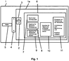
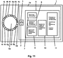
- FIG. 1 the essential components of such a revolution counter system 1 with a revolution counter 1a according to the invention and a magnet system 4 with north pole (N) and south pole (S) mounted on a rotating shaft 5.
- the revolution counter 1a consists of the main components: Revolution sensor US 2, 360 ° - WS 3 angle sensor and electronics 6. Sensors 2 and 3 are stationary and detect the angular position and the number of revolutions of the rotating magnetic field.
- the electronics 6 contain power supplies 7 for the sensors 2 and 3 and the processing of the measured values, a memory 8 for the measured values of the angle sensor 3 and a memory 9 for the measured values of the rotation sensor 2, a memory 10 for setpoint values of the rotation sensor 2 stored in a table and one Processing unit 11, which compares the measured values from memories 8 and 9 with the table values of memory 10 and outputs the result of each measurement.
- the distance between the two adjacent domain walls DW 111 and DW 112 is 540 ° viewed in the cw direction.
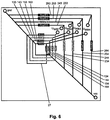
- Figure 5 shows an example of the bond contact savings achieved and aimed at according to the task on the basis of Fig. 4 in a more complete chip view of the rotation sensor.
- Figure 5 shows the rotation sensor 2 from Figure 4 on a chip 202 with bond contacts.
- the reference direction 28 of the GMR layer stack is diagonal to the square spiral and points from the bottom left to the top right.
- Bond contact 270 connects gnd contact 70
- bond contact 291 connects center contact 91
- bond contact 293 connects center contact 93
- bond contact 295 connects center contact 95
- bond contact 297 connects center contact 97
- bond contact 280 connects Vcc contact 80
- bond contacts 225a and 225b connect the ends the conductor track 25 with the bottleneck 26.
- the size and number of bond contacts essentially determine the chip size.
- the 360 ° contact according to the invention saved four bond contacts in this example. This effect becomes clearer when a higher number of turns is provided in the sensor 2 for counting larger numbers of revolutions.
- a revolution counter for 30 revolutions only a maximum of 32 (Vcc + gnd + 30 center contacts) instead of 62 bond contacts, as previously required according to the prior art (namely : Vcc + gnd + 60 center contacts), or with a 5x multiplexing only 16 (namely: 5 Vcc + 5 gnd + 6 center contacts) instead of 22 bond contacts (namely: 5 Vcc + 5 gnd + 12 center contacts) are required.
- the multiplexed reading of the Wheatstone half-bridge signals takes place one after the other with a clock frequency in the MHz range, while the measurement intervals are in the kHz range, and thus quasi simultaneously. This goes hand in hand with a reduction in bond contacts to 48% and 27%, respectively. Since the chip area is largely determined by the size and number of bond contacts connected to the spiral contacts, this minimizes the chip area per sensor element by 25% or 10%, as was determined using layout simulations.
- the readout electronics process all measured signal levels of the five half bridges at the same time, for example as a signal level sequence (SPF) from turn 1 to turn 5, and compare these with setpoint values stored in memory 10.
- the SPF for Figure 7 is in the example shown: L / L / H / H / H.
- FIG. 9 There are according to the sensor element according to the example shown Fig. 7 three revolutions can be counted one-to-one.
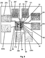
- Figure 8 the domain wall layer after three cw revolutions.
- the DW 111 and DW 112 and the DW gaps DWL 221 and DWL 222 in between were transported twelve DW layers, ie three turns, into the in Fig. 8 positions shown.
- the positions of DW 111 and DW 112 thus represent the number of revolutions three.
- the magnetization direction of the webs in WHB4 and WHB5 is ccw and that of the webs in WHB1, WHB2 and WHB3 is cw, again indicated by arrows on the domain wall interconnects.
- the signal levels of the Wheatstone half bridges are after three 360 ° rotations: • WHB1 (winding 1): H • WHB2 (winding 2): H • WHB3 (winding 3): H • WHB4 (turn 4): L. • WHB5 (winding 5): L.
- the SPF after three turns is therefore H / H / H / L / L.
- the SPF-MM with the levels L / L within the SPF has been transported one position further to the right with each counted revolution. This correlates with the further transport of the domain walls DW 111 and DW 112 into the next turn with each counted revolution.
- the design of the sensor element 2 in the form of two partial spirals with the same direction of winding rotation has the advantage of a smaller design option the overall spiral, compared, for example, with an apprenticeship Figure 3 and thus a saving in the required chip area.
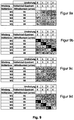
- Figure 9 shows for the sensor element Figure 7 and Figure 8 in table form for the field angle quadrant 1 specified by the quadrant or angle sensor 3 ( Figure 9a ), Field angle quadrant 2 ( Figure 9b ), Field angle quadrant 3 ( Figure 9c ) and field angle quadrant 4 ( Figure 9d ) the setpoint signal level sequences for the revolutions 0, 1, 2 and 3 for the five windings W1 to W5 according to Fig. 7 .
- Each quadrant has its own significant SPF-MM and its own unique SPF for each revolution.
- the significant SPF-MM for quadrant Q1 is L / L, for Q2 M / L, for Q3 L and for Q4 L / M, where H stands for a Wheatstone half-bridge signal level high, M for medium and L for a low level.
- the above-mentioned significant SPF-MM are in the tables of Fig. 9 each highlighted in medium or dark gray.
- at least one sub-table with all SPFs for all permissible (ie countable) revolutions is kept for each individual quadrant, which in Figures 9a to 9d are listed by way of example.
- the readout electronics 11 first determine the field angle quadrant in which the system is currently located, ie the position of the rotating element 4 (for example after Fig. 1 ). After this determination, the readout electronics 11 searches for the sub-table associated with the selected quadrant and then compares the measured SPF with the SPF setpoint values of the corresponding quadrant. In the example this would be quadrant 1 ( Figure 9a ). From this subtable, the evaluation electronics 11 then immediately determine the associated number of revolutions (match of the SPFs) by comparing the measured values in memory 9 with the setpoint signal level sequences held in memory 10, which can then be output / displayed. In the example, the Signal level sequence according to Fig. 7 the number of revolutions zero and the signal level sequence according to Fig. 8 the number of revolutions three, as one can easily see by comparison with the preceding explanations. The procedure is analogous if another field angle quadrant specifies the selection of the associated subtable.
- FIG. 11 shows Figure 11 the revolution counter 1a off Figure 1 combined with a pole wheel 5a with magnetic poles 4a to 4l instead of a magnet 4 on a shaft 5 according to FIG Fig. 1 .
- the pole wheel 5a When the pole wheel 5a is rotated, it generates a rotating magnetic field at the location of the angle sensor WS 3 and the rotation sensor US 2, which moves the domain walls of the magnetization pattern in the sensor element 2.
- Each pole wheel position thus corresponds to an angle sensor measured value and a revolution counter measured value.
- the revolution counter counts the number of magnetic pole pairs moved past. This is analogous to counting revolutions of the magnet 4 according to FIG Fig. 1 .
- Figure 12 shows the revolution counter 1a Fig. 1 combined with a linear scale 5b with magnetic poles 4a to 4l instead of a magnet 4 on a shaft 5 according to FIG Fig. 1 .
- the linear scale 5b with, in the example, twelve magnetic poles (6 north poles alternating with 6 south poles) 4a to 4l also represents other linear scales with more or fewer magnetic poles.
- the scale 5b When the scale 5b is moved past the revolution counter 1a, it generates a rotating magnetic field at the location of the angle sensor WS 3 and the revolution sensor US 2, which moves the domain walls of the impressed magnetization pattern in the sensor element 2.
- Each scale position thus corresponds to an angle sensor measured value and a revolution counter measured value.
- the revolution counter counts the number of magnetic pole pairs moved past. This is analogous to counting revolutions of the magnet 4 according to FIG Fig. 1 .
- Figure 14 shows the rotation sensor of Figure 13a with a modified contact in which the resistances are read out.
- This loop is electrically contacted with the gnd contacts 71, 72, 73 and 74 and the Vcc contacts 81, 82, 83 and 84, one gnd and one Vcc contact on one turn.
- the Vcc contacts for example, must each contact the soft magnetic layer and the gnd contacts each contact the hard magnetic layer (analogous to Figure 13b , in which the center contact 91 contacts the soft magnetic layer 501 and the gnd tunnel contact 71 contacts the hard magnetic layer), or vice versa.
- the contacts can differ from Figure 14 instead of being positioned over the corners on the webs, preferably on opposing webs.
Landscapes
- Physics & Mathematics (AREA)
- General Physics & Mathematics (AREA)
- Condensed Matter Physics & Semiconductors (AREA)
- Engineering & Computer Science (AREA)
- Signal Processing (AREA)
- Transmission And Conversion Of Sensor Element Output (AREA)
- Measuring Magnetic Variables (AREA)
- Measurement Of Length, Angles, Or The Like Using Electric Or Magnetic Means (AREA)
Priority Applications (1)
| Application Number | Priority Date | Filing Date | Title |
|---|---|---|---|
| PL16828920T PL3387388T3 (pl) | 2015-12-11 | 2016-12-07 | Magnetyczny licznik obrotów i sposób określania liczby obrotów, które mogą być określone za pomocą wspomnianego licznika obrotów |
Applications Claiming Priority (2)
| Application Number | Priority Date | Filing Date | Title |
|---|---|---|---|
| DE102015016163 | 2015-12-11 | ||
| PCT/DE2016/000434 WO2017097285A1 (de) | 2015-12-11 | 2016-12-07 | Magnetischer umdrehungszähler und verfahren zur bestimmung von mit diesem umdrehungszähler ermittelbaren umdrehungszahlen |
Publications (2)
| Publication Number | Publication Date |
|---|---|
| EP3387388A1 EP3387388A1 (de) | 2018-10-17 |
| EP3387388B1 true EP3387388B1 (de) | 2021-03-10 |
Family
ID=57850823
Family Applications (1)
| Application Number | Title | Priority Date | Filing Date |
|---|---|---|---|
| EP16828920.5A Active EP3387388B1 (de) | 2015-12-11 | 2016-12-07 | Magnetischer umdrehungszähler und verfahren zur bestimmung von mit diesem umdrehungszähler ermittelbaren umdrehungszahlen |
Country Status (9)
| Country | Link |
|---|---|
| US (1) | US10962386B2 (pl) |
| EP (1) | EP3387388B1 (pl) |
| JP (1) | JP6855499B2 (pl) |
| CN (1) | CN108369110B (pl) |
| DE (1) | DE112016005622A5 (pl) |
| ES (1) | ES2870923T3 (pl) |
| PL (1) | PL3387388T3 (pl) |
| PT (1) | PT3387388T (pl) |
| WO (1) | WO2017097285A1 (pl) |
Cited By (1)
| Publication number | Priority date | Publication date | Assignee | Title |
|---|---|---|---|---|
| US12546631B2 (en) | 2020-11-20 | 2026-02-10 | Analog Devices International Unlimited Company | Magnetic sensing device |
Families Citing this family (31)
| Publication number | Priority date | Publication date | Assignee | Title |
|---|---|---|---|---|
| PL3387387T3 (pl) * | 2015-12-11 | 2020-07-13 | Leibniz-Institut Für Photonische Technologien E.V. | Magnetyczny licznik obrotów do samoczynnego wykrywania stanu błędów przy oznaczaniu wartości obrotowych określanych przez ten licznik obrotów |
| PL3387388T3 (pl) * | 2015-12-11 | 2021-10-11 | Leibniz-Institut Für Photonische Technologien E.V. | Magnetyczny licznik obrotów i sposób określania liczby obrotów, które mogą być określone za pomocą wspomnianego licznika obrotów |
| US10782153B2 (en) | 2016-03-08 | 2020-09-22 | Analog Devices Global | Multiturn sensor arrangement and readout |
| US10724844B2 (en) * | 2017-12-22 | 2020-07-28 | Infineon Technologies Ag | Multi-turn counter sensor |
| US11248971B2 (en) * | 2018-02-02 | 2022-02-15 | Analog Devices International Unlimited Company | Magnetic field torque and/or angle sensor |
| US10830613B2 (en) * | 2018-03-26 | 2020-11-10 | Analog Devices Global Unlimited Company | Turn count decoding for multi-turn sensors |
| US20190383645A1 (en) | 2018-06-13 | 2019-12-19 | Analog Devices Global Unlimited Company | Initialization state determination of a magnetic multi-turn sensor |
| US11614341B2 (en) * | 2018-06-14 | 2023-03-28 | Analog Devices International Unlimited Company | Methods and devices for using multi-turn magnetic sensors with extended magnetic windows |
| JP6791237B2 (ja) * | 2018-12-28 | 2020-11-25 | Tdk株式会社 | 磁気センサ装置 |
| JP6806133B2 (ja) * | 2018-12-28 | 2021-01-06 | Tdk株式会社 | 磁気センサ装置 |
| US11460521B2 (en) * | 2019-03-18 | 2022-10-04 | Analog Devices International Unlimited Company | Multiturn sensor arrangement |
| CN110100548B (zh) * | 2019-06-19 | 2021-08-24 | 南京农业大学 | 一种单轨道式施肥机精准定位方法 |
| DE102019119670A1 (de) * | 2019-07-19 | 2021-01-21 | Infineon Technologies Ag | Umdrehungszähler und Abtasten eines Drehwinkels |
| US11448528B2 (en) | 2019-08-02 | 2022-09-20 | Analog Devices International Unlimited Company | Resettable closed-loop multi-turn magnetic sensor |
| DE102019218351A1 (de) * | 2019-11-27 | 2021-05-27 | Dr. Johannes Heidenhain Gesellschaft Mit Beschränkter Haftung | Sensorelement zur Speicherung von Umdrehungs- oder Positionsinformationen |
| JP2021143969A (ja) | 2020-03-13 | 2021-09-24 | Tdk株式会社 | 磁場検出装置、回転検出装置および電動パワーステアリング装置 |
| US11761793B2 (en) | 2020-05-26 | 2023-09-19 | Analog Devices International Unlimited Company | Magnetic sensor package |
| US11519751B2 (en) | 2020-05-29 | 2022-12-06 | Analog Devices International Unlimited Company | Method of monitoring a magnetic sensor |
| US11637482B2 (en) | 2020-10-08 | 2023-04-25 | Analog Devices International Unlimited Company | Magnetic sensor system for motor control |
| DE102020132914A1 (de) * | 2020-12-10 | 2022-06-15 | Analog Devices International Unlimited Company | Initialisierungsvorrichtung |
| DE102021200204A1 (de) | 2021-01-12 | 2022-07-14 | Festo Se & Co. Kg | Fluidische Stellvorrichtung, System und Verfahren |
| US11460323B2 (en) | 2021-02-05 | 2022-10-04 | Analog Devices International Unlimited Company | Magnetic field sensor package |
| US11808610B2 (en) | 2021-02-09 | 2023-11-07 | Asahi Kasei Microdevices Corporation | Position detection apparatus, position detection system, and position detection method |
| US12038308B2 (en) * | 2021-03-24 | 2024-07-16 | Analog Devices International Unlimited Company | Magnetic sensor system having an initialization conductor |
| DE102021112601A1 (de) * | 2021-05-14 | 2022-11-17 | Infineon Technologies Ag | Vorrichtungen mit Drehungszähler und zugehörige Herstellungsverfahren |
| DE102021004187B3 (de) * | 2021-08-12 | 2022-06-30 | Horst Siedle Gmbh & Co. Kg. | Umdrehungszähler unter Verwendung magnetischer Domänenwandleitbahnen, die schleifenartig verwunden und in sich geschlossen ausgeführt sind |
| WO2024074462A1 (en) * | 2022-10-04 | 2024-04-11 | Analog Devices International Unlimited Company | A tunnel magnetoresistive multi-turn sensor |
| US20240111005A1 (en) * | 2022-10-04 | 2024-04-04 | Analog Devices International Unlimited Company | Tunnel magnetoresistive multi-turn sensor |
| WO2024074460A1 (en) * | 2022-10-04 | 2024-04-11 | Analog Devices International Unlimited Company | A tunnel magnetoresistive multi-turn sensor |
| US12510378B2 (en) | 2023-07-31 | 2025-12-30 | Analog Devices International Unlimited Company | Multi-turn magnetic sensor mid-range reset |
| DE102024120473A1 (de) * | 2023-07-31 | 2025-02-06 | Analog Devices International Unlimited Company | Multiturn-Magneterfassung mit Mittelbereichsrückstellung und/oder Rollover-Zählung |
Family Cites Families (25)
| Publication number | Priority date | Publication date | Assignee | Title |
|---|---|---|---|---|
| DE10162752A1 (de) * | 2001-12-20 | 2003-07-03 | Philips Intellectual Property | Magnetoresistiver Sensor |
| DE10239904A1 (de) * | 2002-08-30 | 2004-03-04 | Horst Siedle Gmbh & Co. Kg. | Sensorelement für einen Umdrehungszähler |
| DE102004020149A1 (de) * | 2004-04-24 | 2005-11-24 | Horst Siedle Gmbh & Co. Kg. | Sensorelement für einen Umdrehungszähler |
| JP4382838B2 (ja) * | 2007-07-27 | 2009-12-16 | 三菱電機株式会社 | 磁気検出装置 |
| CN101836087B (zh) * | 2007-08-27 | 2012-06-13 | 实景技术协会研究所 | 磁性转数计 |
| DE102008063226A1 (de) | 2008-12-23 | 2010-07-01 | Institut Für Photonische Technologien E.V. | Magnetischer Umdrehungszähler |
| DE102010010893B4 (de) * | 2009-03-10 | 2013-04-11 | Horst Siedle Gmbh & Co. Kg | Elektrische Schaltung insbesondere für einen Umdrehungszähler |
| DE102010022611B4 (de) * | 2010-06-01 | 2015-02-19 | Leibniz-Institut für Photonische Technologien e. V. | Magnetischer Umdrehungszähler |
| DE102011075306B4 (de) * | 2011-05-05 | 2025-05-22 | Horst Siedle Gmbh & Co. Kg | Sensorelement insbesondere für einen Umdrehungszähler |
| EP2844955B1 (de) | 2012-04-30 | 2016-05-11 | Fritz Kübler GmbH Zähl-und Sensortechnik | Energieautarker multiturn-drehgeber und verfahren zur ermittlung einer eindeutigen position einer geberwelle mit dem multiturn-drehgeber |
| DE102013018680B4 (de) | 2013-11-04 | 2022-05-25 | Leibniz-Institut für Photonische Technologien e. V. | Magnetischer Sensor zur absoluten Zählung von Umdrehungen oder linearen Wegstrecken |
| US9958511B2 (en) * | 2014-12-08 | 2018-05-01 | Infineon Technologies Ag | Soft switching of magnetization in a magnetoresistive sensor |
| DE102015210586A1 (de) * | 2015-06-10 | 2016-12-15 | Schaeffler Technologies AG & Co. KG | Verfahren zum Betrieb eines Umdrehungssensors und entsprechender Umdrehungssensor |
| PL3387387T3 (pl) * | 2015-12-11 | 2020-07-13 | Leibniz-Institut Für Photonische Technologien E.V. | Magnetyczny licznik obrotów do samoczynnego wykrywania stanu błędów przy oznaczaniu wartości obrotowych określanych przez ten licznik obrotów |
| PL3387388T3 (pl) * | 2015-12-11 | 2021-10-11 | Leibniz-Institut Für Photonische Technologien E.V. | Magnetyczny licznik obrotów i sposób określania liczby obrotów, które mogą być określone za pomocą wspomnianego licznika obrotów |
| US10782153B2 (en) * | 2016-03-08 | 2020-09-22 | Analog Devices Global | Multiturn sensor arrangement and readout |
| DE112017001469T5 (de) * | 2016-03-22 | 2018-12-06 | Panasonic Intellectual Property Management Co., Ltd. | Drehdetektionsvorrichtung mit Korrekturverfahren |
| DE102017005562B4 (de) * | 2016-07-06 | 2024-06-06 | Leibniz-Institut für Photonische Technologien e. V. | Magnetischer Umdrehungszähler |
| DE112017003532T5 (de) * | 2016-07-12 | 2019-04-04 | Panasonic Intellectual Property Management Co., Ltd. | Magnetsensor und Detektionsvorrichtung, die ihn verwendet |
| JP2019097257A (ja) * | 2017-11-20 | 2019-06-20 | オムロンオートモーティブエレクトロニクス株式会社 | 磁極方向検出装置 |
| US10724844B2 (en) * | 2017-12-22 | 2020-07-28 | Infineon Technologies Ag | Multi-turn counter sensor |
| US10830613B2 (en) * | 2018-03-26 | 2020-11-10 | Analog Devices Global Unlimited Company | Turn count decoding for multi-turn sensors |
| US10670386B2 (en) * | 2018-04-19 | 2020-06-02 | Infineon Technologies Ag | Multi-turn counter sensor failure detection |
| US20190383645A1 (en) * | 2018-06-13 | 2019-12-19 | Analog Devices Global Unlimited Company | Initialization state determination of a magnetic multi-turn sensor |
| US11614341B2 (en) * | 2018-06-14 | 2023-03-28 | Analog Devices International Unlimited Company | Methods and devices for using multi-turn magnetic sensors with extended magnetic windows |
-
2016
- 2016-12-07 PL PL16828920T patent/PL3387388T3/pl unknown
- 2016-12-07 WO PCT/DE2016/000434 patent/WO2017097285A1/de not_active Ceased
- 2016-12-07 CN CN201680072570.9A patent/CN108369110B/zh active Active
- 2016-12-07 US US16/060,522 patent/US10962386B2/en active Active
- 2016-12-07 DE DE112016005622.2T patent/DE112016005622A5/de not_active Withdrawn
- 2016-12-07 ES ES16828920T patent/ES2870923T3/es active Active
- 2016-12-07 PT PT168289205T patent/PT3387388T/pt unknown
- 2016-12-07 EP EP16828920.5A patent/EP3387388B1/de active Active
- 2016-12-07 JP JP2018548268A patent/JP6855499B2/ja active Active
Non-Patent Citations (1)
| Title |
|---|
| None * |
Cited By (1)
| Publication number | Priority date | Publication date | Assignee | Title |
|---|---|---|---|---|
| US12546631B2 (en) | 2020-11-20 | 2026-02-10 | Analog Devices International Unlimited Company | Magnetic sensing device |
Also Published As
| Publication number | Publication date |
|---|---|
| CN108369110B (zh) | 2021-09-17 |
| ES2870923T3 (es) | 2021-10-28 |
| US10962386B2 (en) | 2021-03-30 |
| US20180372510A1 (en) | 2018-12-27 |
| JP2019502134A (ja) | 2019-01-24 |
| DE112016005622A5 (de) | 2018-11-08 |
| PL3387388T3 (pl) | 2021-10-11 |
| EP3387388A1 (de) | 2018-10-17 |
| CN108369110A (zh) | 2018-08-03 |
| WO2017097285A1 (de) | 2017-06-15 |
| JP6855499B2 (ja) | 2021-04-07 |
| PT3387388T (pt) | 2021-04-07 |
Similar Documents
| Publication | Publication Date | Title |
|---|---|---|
| EP3387388B1 (de) | Magnetischer umdrehungszähler und verfahren zur bestimmung von mit diesem umdrehungszähler ermittelbaren umdrehungszahlen | |
| EP3387387B1 (de) | Magnetischer umdrehungszähler zur selbsterkennung von fehlerzuständen bei der bestimmung von mit diesem umdrehungszähler ermittelbaren umdrehungszahlen | |
| EP3066421B1 (de) | Magnetischer sensor zur absoluten zählung von umdrehungen oder linearen wegstrecken | |
| DE102017124542B4 (de) | Magnetfeldsensoranordnung und verfahren zum messen eines externen magnetfelds | |
| DE102008063226A1 (de) | Magnetischer Umdrehungszähler | |
| EP2191237B1 (de) | Magnetischer umdrehungszähler | |
| DE102010022611B4 (de) | Magnetischer Umdrehungszähler | |
| DE102010010893B4 (de) | Elektrische Schaltung insbesondere für einen Umdrehungszähler | |
| DE102019116010B4 (de) | Initialisierungszustandsbestimmung eines magnetischen multiturn-sensors | |
| EP1438721B1 (de) | Halbleiterspeicher mit sich kreuzenden wort- und bitleitungen, an denen magnetoresistive speicherzellen angeordnet sind | |
| DE102017005562B4 (de) | Magnetischer Umdrehungszähler | |
| DE102011075306B4 (de) | Sensorelement insbesondere für einen Umdrehungszähler | |
| WO2004020952A2 (de) | Sensorelement für einen umdrehungszähler | |
| WO2016198062A1 (de) | Verfahren zum betrieb eines umdrehungssensors und entsprechender umdrehungssensor | |
| DE19532674C1 (de) | Drehwinkelgeber unter Verwendung von Giant Magnetowiderstandsmaterialien | |
| DE102016113207A1 (de) | Rotationserkennungsvorrichtung | |
| WO2004048986A2 (de) | Magnetoresistives sensorelement und verfahren zur reduktion des winkelfehlers eines magnetoresistiven | |
| DE102019122188A1 (de) | Winkelsensorsystem | |
| DE102011080050B4 (de) | Elektrische Schaltung, insbesondere für einen Umdrehungszähler | |
| DE19936582A1 (de) | Code mit möglichst unterschiedlichen aufeinanderfolgenden Codeelementen | |
| DE10162849B4 (de) | Längenmesssystem, bei dem ein Massstab relativ zur Position von beabstandeten Längensensoren bewegt wird | |
| WO2001018816A1 (de) | Speicherzellenanordnung und verfahren zu deren betrieb | |
| DE19712833C2 (de) | Einrichtung zur berührungslosen Positionserfassung eines Objektes und Verwendung der Einrichtung | |
| WO2000017660A1 (de) | Elektronisches bauelement | |
| DE102019103522A1 (de) | Sensorvorrichtung und Betriebsverfahren hierfür |
Legal Events
| Date | Code | Title | Description |
|---|---|---|---|
| STAA | Information on the status of an ep patent application or granted ep patent |
Free format text: STATUS: UNKNOWN |
|
| STAA | Information on the status of an ep patent application or granted ep patent |
Free format text: STATUS: THE INTERNATIONAL PUBLICATION HAS BEEN MADE |
|
| PUAI | Public reference made under article 153(3) epc to a published international application that has entered the european phase |
Free format text: ORIGINAL CODE: 0009012 |
|
| STAA | Information on the status of an ep patent application or granted ep patent |
Free format text: STATUS: REQUEST FOR EXAMINATION WAS MADE |
|
| 17P | Request for examination filed |
Effective date: 20180615 |
|
| AK | Designated contracting states |
Kind code of ref document: A1 Designated state(s): AL AT BE BG CH CY CZ DE DK EE ES FI FR GB GR HR HU IE IS IT LI LT LU LV MC MK MT NL NO PL PT RO RS SE SI SK SM TR |
|
| AX | Request for extension of the european patent |
Extension state: BA ME |
|
| DAV | Request for validation of the european patent (deleted) | ||
| DAX | Request for extension of the european patent (deleted) | ||
| GRAP | Despatch of communication of intention to grant a patent |
Free format text: ORIGINAL CODE: EPIDOSNIGR1 |
|
| STAA | Information on the status of an ep patent application or granted ep patent |
Free format text: STATUS: GRANT OF PATENT IS INTENDED |
|
| INTG | Intention to grant announced |
Effective date: 20200917 |
|
| GRAS | Grant fee paid |
Free format text: ORIGINAL CODE: EPIDOSNIGR3 |
|
| GRAA | (expected) grant |
Free format text: ORIGINAL CODE: 0009210 |
|
| STAA | Information on the status of an ep patent application or granted ep patent |
Free format text: STATUS: THE PATENT HAS BEEN GRANTED |
|
| AK | Designated contracting states |
Kind code of ref document: B1 Designated state(s): AL AT BE BG CH CY CZ DE DK EE ES FI FR GB GR HR HU IE IS IT LI LT LU LV MC MK MT NL NO PL PT RO RS SE SI SK SM TR |
|
| REG | Reference to a national code |
Ref country code: GB Ref legal event code: FG4D Free format text: NOT ENGLISH |
|
| REG | Reference to a national code |
Ref country code: CH Ref legal event code: EP Ref country code: AT Ref legal event code: REF Ref document number: 1370310 Country of ref document: AT Kind code of ref document: T Effective date: 20210315 |
|
| REG | Reference to a national code |
Ref country code: DE Ref legal event code: R096 Ref document number: 502016012581 Country of ref document: DE |
|
| REG | Reference to a national code |
Ref country code: IE Ref legal event code: FG4D Free format text: LANGUAGE OF EP DOCUMENT: GERMAN |
|
| REG | Reference to a national code |
Ref country code: PT Ref legal event code: SC4A Ref document number: 3387388 Country of ref document: PT Date of ref document: 20210407 Kind code of ref document: T Free format text: AVAILABILITY OF NATIONAL TRANSLATION Effective date: 20210330 |
|
| REG | Reference to a national code |
Ref country code: SE Ref legal event code: TRGR |
|
| REG | Reference to a national code |
Ref country code: NL Ref legal event code: FP |
|
| REG | Reference to a national code |
Ref country code: LT Ref legal event code: MG9D |
|
| PG25 | Lapsed in a contracting state [announced via postgrant information from national office to epo] |
Ref country code: BG Free format text: LAPSE BECAUSE OF FAILURE TO SUBMIT A TRANSLATION OF THE DESCRIPTION OR TO PAY THE FEE WITHIN THE PRESCRIBED TIME-LIMIT Effective date: 20210610 Ref country code: LT Free format text: LAPSE BECAUSE OF FAILURE TO SUBMIT A TRANSLATION OF THE DESCRIPTION OR TO PAY THE FEE WITHIN THE PRESCRIBED TIME-LIMIT Effective date: 20210310 Ref country code: FI Free format text: LAPSE BECAUSE OF FAILURE TO SUBMIT A TRANSLATION OF THE DESCRIPTION OR TO PAY THE FEE WITHIN THE PRESCRIBED TIME-LIMIT Effective date: 20210310 Ref country code: GR Free format text: LAPSE BECAUSE OF FAILURE TO SUBMIT A TRANSLATION OF THE DESCRIPTION OR TO PAY THE FEE WITHIN THE PRESCRIBED TIME-LIMIT Effective date: 20210611 Ref country code: HR Free format text: LAPSE BECAUSE OF FAILURE TO SUBMIT A TRANSLATION OF THE DESCRIPTION OR TO PAY THE FEE WITHIN THE PRESCRIBED TIME-LIMIT Effective date: 20210310 Ref country code: NO Free format text: LAPSE BECAUSE OF FAILURE TO SUBMIT A TRANSLATION OF THE DESCRIPTION OR TO PAY THE FEE WITHIN THE PRESCRIBED TIME-LIMIT Effective date: 20210610 |
|
| PG25 | Lapsed in a contracting state [announced via postgrant information from national office to epo] |
Ref country code: RS Free format text: LAPSE BECAUSE OF FAILURE TO SUBMIT A TRANSLATION OF THE DESCRIPTION OR TO PAY THE FEE WITHIN THE PRESCRIBED TIME-LIMIT Effective date: 20210310 Ref country code: LV Free format text: LAPSE BECAUSE OF FAILURE TO SUBMIT A TRANSLATION OF THE DESCRIPTION OR TO PAY THE FEE WITHIN THE PRESCRIBED TIME-LIMIT Effective date: 20210310 |
|
| REG | Reference to a national code |
Ref country code: ES Ref legal event code: FG2A Ref document number: 2870923 Country of ref document: ES Kind code of ref document: T3 Effective date: 20211028 |
|
| PG25 | Lapsed in a contracting state [announced via postgrant information from national office to epo] |
Ref country code: EE Free format text: LAPSE BECAUSE OF FAILURE TO SUBMIT A TRANSLATION OF THE DESCRIPTION OR TO PAY THE FEE WITHIN THE PRESCRIBED TIME-LIMIT Effective date: 20210310 Ref country code: SM Free format text: LAPSE BECAUSE OF FAILURE TO SUBMIT A TRANSLATION OF THE DESCRIPTION OR TO PAY THE FEE WITHIN THE PRESCRIBED TIME-LIMIT Effective date: 20210310 |
|
| PG25 | Lapsed in a contracting state [announced via postgrant information from national office to epo] |
Ref country code: RO Free format text: LAPSE BECAUSE OF FAILURE TO SUBMIT A TRANSLATION OF THE DESCRIPTION OR TO PAY THE FEE WITHIN THE PRESCRIBED TIME-LIMIT Effective date: 20210310 Ref country code: SK Free format text: LAPSE BECAUSE OF FAILURE TO SUBMIT A TRANSLATION OF THE DESCRIPTION OR TO PAY THE FEE WITHIN THE PRESCRIBED TIME-LIMIT Effective date: 20210310 Ref country code: IS Free format text: LAPSE BECAUSE OF FAILURE TO SUBMIT A TRANSLATION OF THE DESCRIPTION OR TO PAY THE FEE WITHIN THE PRESCRIBED TIME-LIMIT Effective date: 20210710 |
|
| REG | Reference to a national code |
Ref country code: DE Ref legal event code: R097 Ref document number: 502016012581 Country of ref document: DE |
|
| PLBE | No opposition filed within time limit |
Free format text: ORIGINAL CODE: 0009261 |
|
| STAA | Information on the status of an ep patent application or granted ep patent |
Free format text: STATUS: NO OPPOSITION FILED WITHIN TIME LIMIT |
|
| PG25 | Lapsed in a contracting state [announced via postgrant information from national office to epo] |
Ref country code: DK Free format text: LAPSE BECAUSE OF FAILURE TO SUBMIT A TRANSLATION OF THE DESCRIPTION OR TO PAY THE FEE WITHIN THE PRESCRIBED TIME-LIMIT Effective date: 20210310 Ref country code: AL Free format text: LAPSE BECAUSE OF FAILURE TO SUBMIT A TRANSLATION OF THE DESCRIPTION OR TO PAY THE FEE WITHIN THE PRESCRIBED TIME-LIMIT Effective date: 20210310 |
|
| 26N | No opposition filed |
Effective date: 20211213 |
|
| PG25 | Lapsed in a contracting state [announced via postgrant information from national office to epo] |
Ref country code: SI Free format text: LAPSE BECAUSE OF FAILURE TO SUBMIT A TRANSLATION OF THE DESCRIPTION OR TO PAY THE FEE WITHIN THE PRESCRIBED TIME-LIMIT Effective date: 20210310 |
|
| PG25 | Lapsed in a contracting state [announced via postgrant information from national office to epo] |
Ref country code: IS Free format text: LAPSE BECAUSE OF FAILURE TO SUBMIT A TRANSLATION OF THE DESCRIPTION OR TO PAY THE FEE WITHIN THE PRESCRIBED TIME-LIMIT Effective date: 20210710 |
|
| PG25 | Lapsed in a contracting state [announced via postgrant information from national office to epo] |
Ref country code: MC Free format text: LAPSE BECAUSE OF FAILURE TO SUBMIT A TRANSLATION OF THE DESCRIPTION OR TO PAY THE FEE WITHIN THE PRESCRIBED TIME-LIMIT Effective date: 20210310 |
|
| REG | Reference to a national code |
Ref country code: CH Ref legal event code: PL |
|
| REG | Reference to a national code |
Ref country code: BE Ref legal event code: MM Effective date: 20211231 |
|
| PG25 | Lapsed in a contracting state [announced via postgrant information from national office to epo] |
Ref country code: LU Free format text: LAPSE BECAUSE OF NON-PAYMENT OF DUE FEES Effective date: 20211207 |
|
| PG25 | Lapsed in a contracting state [announced via postgrant information from national office to epo] |
Ref country code: BE Free format text: LAPSE BECAUSE OF NON-PAYMENT OF DUE FEES Effective date: 20211231 |
|
| PG25 | Lapsed in a contracting state [announced via postgrant information from national office to epo] |
Ref country code: LI Free format text: LAPSE BECAUSE OF NON-PAYMENT OF DUE FEES Effective date: 20211231 Ref country code: CH Free format text: LAPSE BECAUSE OF NON-PAYMENT OF DUE FEES Effective date: 20211231 |
|
| PG25 | Lapsed in a contracting state [announced via postgrant information from national office to epo] |
Ref country code: HU Free format text: LAPSE BECAUSE OF FAILURE TO SUBMIT A TRANSLATION OF THE DESCRIPTION OR TO PAY THE FEE WITHIN THE PRESCRIBED TIME-LIMIT; INVALID AB INITIO Effective date: 20161207 |
|
| PG25 | Lapsed in a contracting state [announced via postgrant information from national office to epo] |
Ref country code: CY Free format text: LAPSE BECAUSE OF FAILURE TO SUBMIT A TRANSLATION OF THE DESCRIPTION OR TO PAY THE FEE WITHIN THE PRESCRIBED TIME-LIMIT Effective date: 20210310 |
|
| PG25 | Lapsed in a contracting state [announced via postgrant information from national office to epo] |
Ref country code: MK Free format text: LAPSE BECAUSE OF FAILURE TO SUBMIT A TRANSLATION OF THE DESCRIPTION OR TO PAY THE FEE WITHIN THE PRESCRIBED TIME-LIMIT Effective date: 20210310 |
|
| PG25 | Lapsed in a contracting state [announced via postgrant information from national office to epo] |
Ref country code: MT Free format text: LAPSE BECAUSE OF FAILURE TO SUBMIT A TRANSLATION OF THE DESCRIPTION OR TO PAY THE FEE WITHIN THE PRESCRIBED TIME-LIMIT Effective date: 20210310 |
|
| PGFP | Annual fee paid to national office [announced via postgrant information from national office to epo] |
Ref country code: ES Payment date: 20250102 Year of fee payment: 9 |
|
| PGFP | Annual fee paid to national office [announced via postgrant information from national office to epo] |
Ref country code: PT Payment date: 20251021 Year of fee payment: 10 |
|
| PGFP | Annual fee paid to national office [announced via postgrant information from national office to epo] |
Ref country code: DE Payment date: 20251201 Year of fee payment: 10 |
|
| PGFP | Annual fee paid to national office [announced via postgrant information from national office to epo] |
Ref country code: GB Payment date: 20251114 Year of fee payment: 10 |
|
| PGFP | Annual fee paid to national office [announced via postgrant information from national office to epo] |
Ref country code: AT Payment date: 20251202 Year of fee payment: 10 |
|
| PGFP | Annual fee paid to national office [announced via postgrant information from national office to epo] |
Ref country code: IT Payment date: 20251022 Year of fee payment: 10 |
|
| PGFP | Annual fee paid to national office [announced via postgrant information from national office to epo] |
Ref country code: FR Payment date: 20251231 Year of fee payment: 10 Ref country code: NL Payment date: 20251223 Year of fee payment: 10 |
|
| PGFP | Annual fee paid to national office [announced via postgrant information from national office to epo] |
Ref country code: TR Payment date: 20251107 Year of fee payment: 10 |
|
| PGFP | Annual fee paid to national office [announced via postgrant information from national office to epo] |
Ref country code: SE Payment date: 20251103 Year of fee payment: 10 |
|
| PGFP | Annual fee paid to national office [announced via postgrant information from national office to epo] |
Ref country code: IE Payment date: 20251128 Year of fee payment: 10 Ref country code: CZ Payment date: 20251119 Year of fee payment: 10 |
|
| PGFP | Annual fee paid to national office [announced via postgrant information from national office to epo] |
Ref country code: PL Payment date: 20251119 Year of fee payment: 10 |