EP3385653B1 - Wärmetauscher - Google Patents
Wärmetauscher Download PDFInfo
- Publication number
- EP3385653B1 EP3385653B1 EP18156127.5A EP18156127A EP3385653B1 EP 3385653 B1 EP3385653 B1 EP 3385653B1 EP 18156127 A EP18156127 A EP 18156127A EP 3385653 B1 EP3385653 B1 EP 3385653B1
- Authority
- EP
- European Patent Office
- Prior art keywords
- plates
- structured
- plate
- heat exchanger
- structured plates
- Prior art date
- Legal status (The legal status is an assumption and is not a legal conclusion. Google has not performed a legal analysis and makes no representation as to the accuracy of the status listed.)
- Active
Links
- 239000012530 fluid Substances 0.000 claims description 75
- 230000007704 transition Effects 0.000 claims description 21
- 238000000926 separation method Methods 0.000 claims description 11
Images


Classifications
-
- F—MECHANICAL ENGINEERING; LIGHTING; HEATING; WEAPONS; BLASTING
- F28—HEAT EXCHANGE IN GENERAL
- F28D—HEAT-EXCHANGE APPARATUS, NOT PROVIDED FOR IN ANOTHER SUBCLASS, IN WHICH THE HEAT-EXCHANGE MEDIA DO NOT COME INTO DIRECT CONTACT
- F28D9/00—Heat-exchange apparatus having stationary plate-like or laminated conduit assemblies for both heat-exchange media, the media being in contact with different sides of a conduit wall
- F28D9/0093—Multi-circuit heat-exchangers, e.g. integrating different heat exchange sections in the same unit or heat-exchangers for more than two fluids
-
- F—MECHANICAL ENGINEERING; LIGHTING; HEATING; WEAPONS; BLASTING
- F28—HEAT EXCHANGE IN GENERAL
- F28D—HEAT-EXCHANGE APPARATUS, NOT PROVIDED FOR IN ANOTHER SUBCLASS, IN WHICH THE HEAT-EXCHANGE MEDIA DO NOT COME INTO DIRECT CONTACT
- F28D9/00—Heat-exchange apparatus having stationary plate-like or laminated conduit assemblies for both heat-exchange media, the media being in contact with different sides of a conduit wall
-
- F—MECHANICAL ENGINEERING; LIGHTING; HEATING; WEAPONS; BLASTING
- F28—HEAT EXCHANGE IN GENERAL
- F28F—DETAILS OF HEAT-EXCHANGE AND HEAT-TRANSFER APPARATUS, OF GENERAL APPLICATION
- F28F3/00—Plate-like or laminated elements; Assemblies of plate-like or laminated elements
- F28F3/08—Elements constructed for building-up into stacks, e.g. capable of being taken apart for cleaning
-
- F—MECHANICAL ENGINEERING; LIGHTING; HEATING; WEAPONS; BLASTING
- F28—HEAT EXCHANGE IN GENERAL
- F28D—HEAT-EXCHANGE APPARATUS, NOT PROVIDED FOR IN ANOTHER SUBCLASS, IN WHICH THE HEAT-EXCHANGE MEDIA DO NOT COME INTO DIRECT CONTACT
- F28D9/00—Heat-exchange apparatus having stationary plate-like or laminated conduit assemblies for both heat-exchange media, the media being in contact with different sides of a conduit wall
- F28D9/0031—Heat-exchange apparatus having stationary plate-like or laminated conduit assemblies for both heat-exchange media, the media being in contact with different sides of a conduit wall the conduits for one heat-exchange medium being formed by paired plates touching each other
- F28D9/0043—Heat-exchange apparatus having stationary plate-like or laminated conduit assemblies for both heat-exchange media, the media being in contact with different sides of a conduit wall the conduits for one heat-exchange medium being formed by paired plates touching each other the plates having openings therein for circulation of at least one heat-exchange medium from one conduit to another
- F28D9/005—Heat-exchange apparatus having stationary plate-like or laminated conduit assemblies for both heat-exchange media, the media being in contact with different sides of a conduit wall the conduits for one heat-exchange medium being formed by paired plates touching each other the plates having openings therein for circulation of at least one heat-exchange medium from one conduit to another the plates having openings therein for both heat-exchange media
-
- F—MECHANICAL ENGINEERING; LIGHTING; HEATING; WEAPONS; BLASTING
- F28—HEAT EXCHANGE IN GENERAL
- F28F—DETAILS OF HEAT-EXCHANGE AND HEAT-TRANSFER APPARATUS, OF GENERAL APPLICATION
- F28F3/00—Plate-like or laminated elements; Assemblies of plate-like or laminated elements
- F28F3/02—Elements or assemblies thereof with means for increasing heat-transfer area, e.g. with fins, with recesses, with corrugations
- F28F3/04—Elements or assemblies thereof with means for increasing heat-transfer area, e.g. with fins, with recesses, with corrugations the means being integral with the element
- F28F3/042—Elements or assemblies thereof with means for increasing heat-transfer area, e.g. with fins, with recesses, with corrugations the means being integral with the element in the form of local deformations of the element
- F28F3/044—Elements or assemblies thereof with means for increasing heat-transfer area, e.g. with fins, with recesses, with corrugations the means being integral with the element in the form of local deformations of the element the deformations being pontual, e.g. dimples
-
- F—MECHANICAL ENGINEERING; LIGHTING; HEATING; WEAPONS; BLASTING
- F28—HEAT EXCHANGE IN GENERAL
- F28F—DETAILS OF HEAT-EXCHANGE AND HEAT-TRANSFER APPARATUS, OF GENERAL APPLICATION
- F28F3/00—Plate-like or laminated elements; Assemblies of plate-like or laminated elements
- F28F3/08—Elements constructed for building-up into stacks, e.g. capable of being taken apart for cleaning
- F28F3/083—Elements constructed for building-up into stacks, e.g. capable of being taken apart for cleaning capable of being taken apart
-
- F—MECHANICAL ENGINEERING; LIGHTING; HEATING; WEAPONS; BLASTING
- F28—HEAT EXCHANGE IN GENERAL
- F28F—DETAILS OF HEAT-EXCHANGE AND HEAT-TRANSFER APPARATUS, OF GENERAL APPLICATION
- F28F2215/00—Fins
- F28F2215/04—Assemblies of fins having different features, e.g. with different fin densities
-
- F—MECHANICAL ENGINEERING; LIGHTING; HEATING; WEAPONS; BLASTING
- F28—HEAT EXCHANGE IN GENERAL
- F28F—DETAILS OF HEAT-EXCHANGE AND HEAT-TRANSFER APPARATUS, OF GENERAL APPLICATION
- F28F2275/00—Fastening; Joining
- F28F2275/20—Fastening; Joining with threaded elements
-
- F—MECHANICAL ENGINEERING; LIGHTING; HEATING; WEAPONS; BLASTING
- F28—HEAT EXCHANGE IN GENERAL
- F28F—DETAILS OF HEAT-EXCHANGE AND HEAT-TRANSFER APPARATUS, OF GENERAL APPLICATION
- F28F9/00—Casings; Header boxes; Auxiliary supports for elements; Auxiliary members within casings
- F28F9/02—Header boxes; End plates
- F28F9/0246—Arrangements for connecting header boxes with flow lines
- F28F9/0248—Arrangements for sealing connectors to header boxes
Definitions
- the invention relates to a heat exchanger according to the preamble of claim 1.
- Such a heat exchanger is known, for example, from WO2015/162936 A1 or WO 2016/038830 A1 .
- a plate heat exchanger heat is usually transferred between a first fluid flowing through primary heat channels and a second fluid flowing through secondary fluid channels.
- the structured plates are stacked on top of each other and fixed between the top and bottom plates by e.g. bolts.
- each structured plate cooperates to form primary fluid channels on one of its sides and secondary fluid channels on the opposite side of the structured plate.
- Plate heat exchangers of the above kind are produced with a plurality of different structured plates and corresponding primary and secondary fluid channels.
- the type and number of structured plates that is used for the heat exchanger and the resulting shape of the fluid channels then defines the characteristics of the heat exchanger like the heat transfer efficiency, flow speed, pressure drop etc.
- Task of the invention is therefore to provide a heat exchanger that can be produced with a wide range of specifications without increasing the costs or production time.
- This solution allows to produce heat exchangers with a wider range of specifications by using stacks of different types of structured plates in the same heat exchanger.
- the individual structured plates can however still be chosen from standard, mass produced types and consequently the production costs and time is not significantly increased compared to a standard heat exchanger.
- the types of structured plates that are used may be chosen such that a cooperation of the adjacent structured plates where different stacks meet is possible or by separating adjacent stacks.
- the structureless separator plate may still comprise openings to allow the inlet and outlet flows for the primary and secondary fluid to flow towards or away from the primary and secondary fluid channels.
- Using a structureless separator plate allows to use different kinds of structured plates that would otherwise not be able to be stacked directly on top of each other. The latter may otherwise result in the failure of the heat exchanger by deformation during assembly or operation.
- At least one transition plate is arranged on each side of the structureless separator plate.
- the transition plates may serve to keep the primary fluid channels and the secondary fluid channels separated despite the presence of the structureless separator plate.
- the transition plates may to this end comprise inlet and outlet structures to allow to direct the flow from the primary and secondary inlet as well as from the primary and secondary outlet from and to the correct fluid channels.
- one of the transition plates is arranged fitting closely to the adjacent structureless plate for the majority of the area of the structureless plate.
- the majority of the area of the structureless plate may here mean the area of the structureless plate excluding the area surrounding one of the inlets and one of the outlets such that the first fluid and the second fluid may still be kept separate.
- one of the transition plates is arranged fitting closely to an adjacent structured plate of one of the adjacent stacks of structured plates for the majority of the area of the adjacent structured plate. As in the previous embodiment this solution allows to keep the primary fluid and the secondary fluid separate in the region adjacent to the separator plate.
- each structured plate comprises at least one primary inlet to and at least one primary outlet from adjacent primary fluid channels, and wherein each structured plate comprises at least one secondary inlet to and at least one secondary outlet from adjacent secondary fluid channels.
- each structureless separator plate as well as each transition plate.
- the structured plates may comprise inlet and outlet structures that are absent in the structureless separator plates.
- a fluid separator structure is arranged in at least one of the structured plates.
- the fluid separation structure may serve to separate the fluid flowing into the primary fluid channel or secondary fluid channel such that the fluid is distributed more effectively over the whole plane of the structured plate.
- At least one fluid separation structure is formed by cooperating ridges of two adjacent structured plates. This embodiment furthermore stabilizes the heat exchanger.
- the structured plates in at least one of the stacks of structured plates form alternating hills and valleys to improve the heat transfer between the fluids and said structured plates.
- more than one of the stacks of structured plates may comprise structured plates with such alternating hills and valleys.
- the heat exchanger may comprise for example two or more stacks of structured plates with alternating hills and valleys wherein the design of the hill and valley structure of the individual stacks is different.
- the structured plates in at least one of the stacks of structured plates form wedge-like structures to improve the heat transfer between the fluids and said structured plates.
- several of the stacks may comprise structured plates with wedge-like structures and/or the wedge-like structures of different stacks may differ in design.
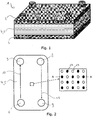
- Fig. 1 shows a simplified depiction of a heat exchanger 1 according to the invention.
- the heat exchanger 1 comprises a top plate 2 as well as a bottom plate 3. Between the top plate 2 and the bottom plate 3 a plurality of structured plates 4, 5 are arranged.
- Fig. 2 shows a simplified top view of a structured plate 4, 5.
- the structured plate comprises a primary inlet 6 as well as primary outlet 7.
- a primary fluid entering through the primary inlet 6 flows over the top side of the structured plate 4, 5 towards the primary outlet 7.
- the structured plate 4, 5 comprises a secondary inlet 8 as well as a secondary outlet 9.
- a secondary fluid flowing along the bottom side of the structured plate 4, 5 enters through the secondary inlet 8 and flows towards the secondary outlet 9. Heat can then be transferred from the primary fluid to the secondary fluid through the structured plate 4, 5.
- the respective inlets and outlets may alternatively be arranged diagonally from each other across the structured plate 4, 5.
- primary fluid channels 10 are thus formed to guide the primary fluid from the primary inlet 6 to the primary outlet 7.
- secondary fluid channels 11 are formed on the bottom side of the structured plate 4, 5 to guide the secondary fluid from the secondary inlet 8 to the secondary outlet 9.
- the primary fluid channels 10 and the secondary fluid channels 11 may be formed by microstructures such as a pattern of alternating hills 12 and valleys 13 as shown in Fig. 2 .
- the structured plates 4, 5 can also comprise different structures, for example, wedge-like structures.
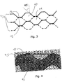
- Fig. 3 shows a side view of four structured plates 4, 5 arranged on top of each other.
- the topmost structured plate 4, 5 cooperates at its valleys 13 with hills 12 of the structured plate arranged directly below. Thereby, primary fluid channels 10 as well as secondary fluid channels 11 are formed.
- Fig. 4 shows an isometric view of a structured plate comprising hills 12 and valleys 13 as in Fig. 2 and 3 .
- Fig. 5a shows a detail of a structured plate 4 cooperating with an adjacent structured plate 5.
- a valley 13 of the structured plate 4 cooperates with a hill 12 of the structured plate 5.
- the structured plates 4, 5 comprise the same microstructure of hills 12 and valleys 13.
- the contact surface of the hills 12 has the same extent as the contact surface of the valleys 13 thereby allowing a good stability of the cooperating adjacent structured plates 4, 5.
- Fig. 5b shows a slightly different situation in which the microstructure of the structured plates 4, 5 is different.
- the extent of the contact surface of the valleys 13 of the structure plate 4 is smaller than the contact surface of the hills 12 of the structured plate 5.
- structured plates 4, 5 with different microstructures can cooperate to form primary fluid channels and secondary fluid channels as long as the structured plates can be stacked in such a way that the cooperating structured plates are sufficiently stable.
- the distance between neighboring hills and valleys would need to be the same for both structured plates 4, 5 to allow them to cooperate to form primary fluid channels and secondary fluid channels despite the difference in shape of the hills 12 and valleys 13.
- Fig. 6 shows a further embodiment of a heat exchanger according to the invention.
- the heat exchanger 1 comprises two stacks of structured plates 14, 15. Between the stacks of structured plates 14, 15 a structureless separator plate 16 is arranged.
- the structureless separator plate 16 allows to combine a broad range of different structured plates 4, 5 in the same heat exchanger 1.
- the microstructures of the structured plates 4, 5 arranged in the stack of structured plates 14 may be different to the microstructures of the structured plates 4, 5 arranged in the stack of structured plates 15.
- the structureless separator plate 16 comprises openings to allow the primary and secondary fluid to flow through the structureless separator plate 16 form one stack of structure plates 14, 15 to the next stack of structure plates 14, 15.
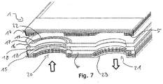
- Fig. 7 shows an exploded cut view of an embodiment of a heat exchanger 1 according to the invention.
- the heat exchanger 1 again comprises two stacks of structured plates 14, 15.
- the heat exchanger 1 may however comprise a larger number of stacks of structured plates 14, 15.
- a structureless separator plate 16 is arranged between the stack of structured plates 14 and the adjacent stack of structured plates 15 .
- a structureless separator plate 16 is arranged between the stack of structured plates 14 and the adjacent stack of structured plates 15 .
- one transition plate 17, 18 is arranged.
- One of the transition plates 17 is arranged fitting closely to the adjacent structureless plate 16 for the majority of the area of the structureless plate 16.
- the transition plate 18 is arranged fitting closely to an adjacent structured plate 4 for the majority of the area of the adjacent structured plate 4.
- transition plates 17, 18 ensure that the primary fluid and the secondary fluid can be kept separate despite the use of the structureless separator plate 16 to separate the stacks of structured plates 14, 15.
- the transition plates 17, 18 may be structureless apart from inlet structures 19 and/or outlet structures formed to block the entry of a primary or a secondary fluid.
- Fig. 7 two arrows show the fluid flow direction through an inlet manifold 20 and an outlet manifold 21.
- the inlet manifold 20 is formed by a plurality of subsequent inlets 22 in adjacent structured plates 4, 5.
- the outlet manifold 21 is formed by a plurality of outlets 23 arranged in adjacent structured plates 4, 5.
- the inlet manifold 20 as well as the outlet manifold 21 may furthermore be formed by inlets 22 and outlets 23 formed in the structureless separator plate 16 and/or in the separator plates 18, 19.
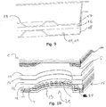
- Fig. 8 shows a further detail of a heat exchanger 1 according to Fig. 6 and 7 .
- Fig. 8 shows a detail of the inlet manifold 20 as shown in Fig. 7 .
- Fig. 8 shows detailed top views of the transition plates 17, 18 as well as the inlet structures 19 arranged in the transition plates 17, 18.
- the transition plates 17, 18 comprise similar outlet structures that may, for example, be arranged on the diagonally opposite side of the transition plates 17, 18.
- Fig. 8 shows a detailed top view of the structure of an inlet 22 of the structured plates 4, 5.
- the inlet 22 here comprises a fluid separation structure 24.
- the fluid separation structure 24 comprises cooperating ridges 25.
- the fluid separation structure 24 serves to separate the fluid flow coming out of the outlet 22 into the corresponding primary fluid channel or secondary fluid channel.
- the use of such a fluid separation structure 24 improves the heat transfer efficiency of the heat exchanger 1. Irrespective of the structures of the structured plates 4, 5, each of the structured plates 4, 5 may comprise the same fluid separation structure 24 but different primary and secondary fluid channels for each stack structured plates 14, 15.
- Fig. 9 shows a cut side view of the cooperation of the structureless separator plate 16 with the adjacent transition plates 17, 18.
- Fig. 9 shows how the inlet structure 19 fits to the structureless separator plate 16.
- a primary fluid channel 10 or a secondary fluid channel 11 may be arranged between the transition plate 18 and the structureless separator plate 16 .
- the transition plate 18 may to this end comprise microstructures (hills and valleys and/or wedge-like structures) to improve the heat transfer but these are omitted for simplicity.
- Fig. 10 shows a detailed view of an outlet manifold 21 as shown in Fig. 7 .
- Fig. 10 shows a detailed isometric view of a fluid separation structure 24.
- Adjacent structured plates 4 may here cooperate by comprising matching ridges 25 to both form the fluid separation structure 24 as well as block the entry of e.g. the secondary fluid flowing into a primary fluid channel 10.
Landscapes
- Engineering & Computer Science (AREA)
- Physics & Mathematics (AREA)
- Thermal Sciences (AREA)
- Mechanical Engineering (AREA)
- General Engineering & Computer Science (AREA)
- Heat-Exchange Devices With Radiators And Conduit Assemblies (AREA)
Claims (8)
- Wärmetauscher (1), der eine obere Platte (2) und eine untere Platte (3) sowie eine Mehrzahl von strukturierten Platten (4, 5) aufweist, die zwischen der oberen Platte (2) und der unteren Platte (3) angeordnet sind, wobei benachbarte strukturierte Platten (4, 5) zusammenwirken, um primäre Fluidkanäle (10) und sekundäre Fluidkanäle (11) zwischen benachbarten strukturierten Platten (4, 5) zu bilden, wobei der Wärmetauscher (1) mindestens zwei Stapel von strukturierten Platten (14, 15) aufweist, wobei die strukturierten Platten (4, 5) in mindestens einem der Stapel von strukturierten Platten (14, 15) unterschiedliche primäre Fluidkanäle (10) und sekundäre Fluidkanäle (11) als die primären Fluidkanäle (10) und die sekundären Fluidkanäle (11) in mindestens einem anderen Stapel von strukturierten Platten (14, 15) bilden, wobei zwischen jedem Paar von benachbarten strukturierten Platten (14, 15) eine strukturlose Trennplatte (16) angeordnet ist, dadurch gekennzeichnet, dass mindestens eine Übergangsplatte (17, 18) auf jeder Seite der strukturlosen Trennplatte (16) angeordnet ist.
- Wärmetauscher (1) nach Anspruch 1, dadurch gekennzeichnet, dass eine der Übergangsplatten (17, 18) eng an die benachbarte strukturlose Platte (16) für den größten Teil der Fläche der strukturlosen Platte (16) angepasst angeordnet ist.
- Wärmetauscher (1) nach Anspruch 1 oder 2, dadurch gekennzeichnet, dass eine der Übergangsplatten (17, 18) eng an einer benachbarten strukturierten Platte (4, 5) eines der benachbarten Stapel von strukturierten Platten (14, 15) für den größten Teil der Fläche der benachbarten strukturierten Platte (4, 5) angeordnet ist.
- Wärmetauscher (1) nach einem der Ansprüche 1 bis 3, dadurch gekennzeichnet, dass jede strukturierte Platte (4, 5) mindestens einen primären Einlass (6) und mindestens einen primären Auslass (7) aus benachbarten primären Fluidkanälen (10) aufweist, und wobei jede strukturierte Platte (4, 5) mindestens einen sekundären Einlass zu und mindestens einen sekundären Auslass aus benachbarten sekundären Fluidkanälen (11) aufweist.
- Wärmetauscher (1) nach Anspruch 4, dadurch gekennzeichnet, dass in mindestens einer der strukturierten Platten (4, 5) mindestens ein primärer Einlass (6) und/oder mindestens ein primärer Auslass (7) und/oder mindestens ein sekundärer Einlass und/oder mindestens ein sekundärer Auslass einer Fluidstruktur (24) angeordnet ist.
- Wärmetauscher (1) nach einem der Ansprüche 1 bis 5, dadurch gekennzeichnet, dass mindestens eine Fluidtrennstruktur (24) durch zusammenwirkende Rippen (25) von zwei benachbarten strukturierten Platten (4, 5) gebildet ist.
- Wärmetauscher (1) nach einem der Ansprüche 1 bis 6, dadurch gekennzeichnet, dass die strukturierten Platten (4, 5) in mindestens einem der Stapel von strukturierten Platten (14, 15) abwechselnd Hügel (12) und Täler (13) bilden, um den Wärmeübergang zwischen den Fluiden und den strukturierten Platten (4, 5) zu verbessern.
- Wärmetauscher (1) nach einem der Ansprüche 1 bis 7, dadurch gekennzeichnet, dass die strukturierten Platten (4, 5) in mindestens einem der Stapel von strukturierten Platten (14, 15) keilförmige Strukturen bilden, um den Wärmeübergang zwischen den Fluiden und den strukturierten Platten (4, 5) zu verbessern.
Priority Applications (2)
| Application Number | Priority Date | Filing Date | Title |
|---|---|---|---|
| PL18156127T PL3385653T3 (pl) | 2017-03-01 | 2018-02-09 | Wymiennik ciepła |
| SI201830024T SI3385653T1 (sl) | 2017-03-01 | 2018-02-09 | Prenosnik toplote |
Applications Claiming Priority (1)
| Application Number | Priority Date | Filing Date | Title |
|---|---|---|---|
| DKPA201700141A DK179183B1 (en) | 2017-03-01 | 2017-03-01 | Dividing plate between Heat plates |
Publications (2)
| Publication Number | Publication Date |
|---|---|
| EP3385653A1 EP3385653A1 (de) | 2018-10-10 |
| EP3385653B1 true EP3385653B1 (de) | 2019-12-04 |
Family
ID=60971529
Family Applications (1)
| Application Number | Title | Priority Date | Filing Date |
|---|---|---|---|
| EP18156127.5A Active EP3385653B1 (de) | 2017-03-01 | 2018-02-09 | Wärmetauscher |
Country Status (6)
| Country | Link |
|---|---|
| EP (1) | EP3385653B1 (de) |
| CN (1) | CN108534571B (de) |
| DK (2) | DK179183B1 (de) |
| PL (1) | PL3385653T3 (de) |
| RU (1) | RU2683061C1 (de) |
| SI (1) | SI3385653T1 (de) |
Cited By (2)
| Publication number | Priority date | Publication date | Assignee | Title |
|---|---|---|---|---|
| EP4464967A1 (de) | 2023-05-16 | 2024-11-20 | Danfoss A/S | Trennplatte |
| EP4464971A1 (de) | 2023-05-16 | 2024-11-20 | Danfoss A/S | Wärmetauscher |
Families Citing this family (1)
| Publication number | Priority date | Publication date | Assignee | Title |
|---|---|---|---|---|
| EP3905286A1 (de) | 2020-04-30 | 2021-11-03 | ABB Power Grids Switzerland AG | Wärmetauscher und elektrische anordnung mit wärmetauscher |
Family Cites Families (12)
| Publication number | Priority date | Publication date | Assignee | Title |
|---|---|---|---|---|
| US3228464A (en) * | 1963-08-09 | 1966-01-11 | Avco Corp | Corrugated plate counter flow heat exchanger |
| DE2048386C3 (de) * | 1970-10-01 | 1974-01-10 | Linde Ag, 6200 Wiesbaden | Plattenwärmetauscher |
| FR2296832A1 (fr) * | 1975-01-06 | 1976-07-30 | Commissariat Energie Atomique | Echangeur de chaleur pour hautes temperatures |
| FR2846733B1 (fr) * | 2002-10-31 | 2006-09-15 | Valeo Thermique Moteur Sa | Condenseur, notamment pour un circuit de cimatisation de vehicule automobile, et circuit comprenant ce condenseur |
| US20110180247A1 (en) * | 2004-09-08 | 2011-07-28 | Ep Technology Ab | Heat exchanger |
| US8079407B2 (en) * | 2006-11-09 | 2011-12-20 | Honeywell International Inc. | Integrated heat exchangers for ECS and OBIGGS applications |
| SE530574C2 (sv) * | 2006-11-20 | 2008-07-08 | Alfa Laval Corp Ab | Plattvärmeväxlare |
| FR2950682B1 (fr) * | 2009-09-30 | 2012-06-01 | Valeo Systemes Thermiques | Condenseur pour vehicule automobile a integration amelioree |
| DK2618089T3 (en) * | 2012-01-23 | 2019-03-18 | Danfoss As | Heat exchanger and method of producing a heat exchanger |
| EP2908080A1 (de) * | 2014-02-13 | 2015-08-19 | Ekocoil Oy | Wärmetauscherstruktur zur Reduzierung der Akkumulation von Flüssigkeit und Gefrieren |
| JP6315191B2 (ja) * | 2014-04-25 | 2018-04-25 | パナソニックIpマネジメント株式会社 | 熱交換器 |
| WO2016038830A1 (ja) * | 2014-09-12 | 2016-03-17 | パナソニックIpマネジメント株式会社 | 熱交換装置 |
-
2017
- 2017-03-01 DK DKPA201700141A patent/DK179183B1/en active
-
2018
- 2018-02-09 SI SI201830024T patent/SI3385653T1/sl unknown
- 2018-02-09 PL PL18156127T patent/PL3385653T3/pl unknown
- 2018-02-09 EP EP18156127.5A patent/EP3385653B1/de active Active
- 2018-02-09 DK DK18156127.5T patent/DK3385653T3/da active
- 2018-02-21 RU RU2018106521A patent/RU2683061C1/ru active
- 2018-03-01 CN CN201810173204.3A patent/CN108534571B/zh active Active
Non-Patent Citations (1)
| Title |
|---|
| None * |
Cited By (2)
| Publication number | Priority date | Publication date | Assignee | Title |
|---|---|---|---|---|
| EP4464967A1 (de) | 2023-05-16 | 2024-11-20 | Danfoss A/S | Trennplatte |
| EP4464971A1 (de) | 2023-05-16 | 2024-11-20 | Danfoss A/S | Wärmetauscher |
Also Published As
| Publication number | Publication date |
|---|---|
| RU2683061C1 (ru) | 2019-03-26 |
| DK3385653T3 (da) | 2020-02-03 |
| PL3385653T3 (pl) | 2020-06-01 |
| SI3385653T1 (sl) | 2020-07-31 |
| CN108534571A (zh) | 2018-09-14 |
| DK201700141A1 (en) | 2018-01-15 |
| EP3385653A1 (de) | 2018-10-10 |
| CN108534571B (zh) | 2020-04-07 |
| DK179183B1 (en) | 2018-01-15 |
Similar Documents
| Publication | Publication Date | Title |
|---|---|---|
| US6199626B1 (en) | Self-enclosing heat exchangers | |
| EP3385653B1 (de) | Wärmetauscher | |
| CN102084205A (zh) | 特别用于机动车的板式热交换器 | |
| KR102243230B1 (ko) | 열전달 판 및 판 열교환기 | |
| JP6871365B2 (ja) | 熱交換板および熱交換器 | |
| EP2929273B1 (de) | Plattenwärmetauscher | |
| CN107429977B (zh) | 具有顶部歧管和底部歧管的堆叠板热交换器 | |
| EP1191297A3 (de) | Plattenwärmetauscher | |
| US9453690B2 (en) | Stacked-plate heat exchanger with single plate design | |
| SE518256C2 (sv) | Värmeöverföringsplatta, plattpaket samt plattvärmeväxlare | |
| EP1702193B1 (de) | Plattenwärmetauscher | |
| EP2775246B1 (de) | Mit Vertiefungsmustern abgedichteter Wärmetauscher | |
| US7044206B2 (en) | Heat exchanger plate and a plate heat exchanger | |
| KR20190075467A (ko) | 기액 분리 구조를 포함하는 인쇄기판형 열교환기 | |
| FI3446059T3 (fi) | Laminoituja mikrokanavalämmönvaihtimia | |
| KR20190075466A (ko) | 중간 플레이트를 포함하는 인쇄기판형 열교환기 | |
| JP2000356483A (ja) | 熱交換器 | |
| US5029640A (en) | Gas-liquid impingement plate type heat exchanger | |
| JP6087640B2 (ja) | 積層型熱交換器 | |
| EP4464967A1 (de) | Trennplatte | |
| EP2618089B1 (de) | Wärmetauscher und verfahren zum herstellen eines wärmetauschers | |
| JP2005083623A (ja) | 熱交換ユニット及び積層型熱交換器 | |
| EP3792580A1 (de) | Plattenwärmetauscher zur behandlung einer flüssigkeitszufuhr | |
| JP7057654B2 (ja) | オイルクーラ | |
| EP4450913A1 (de) | Plattenwärmetauscher |
Legal Events
| Date | Code | Title | Description |
|---|---|---|---|
| PUAI | Public reference made under article 153(3) epc to a published international application that has entered the european phase |
Free format text: ORIGINAL CODE: 0009012 |
|
| STAA | Information on the status of an ep patent application or granted ep patent |
Free format text: STATUS: THE APPLICATION HAS BEEN PUBLISHED |
|
| AK | Designated contracting states |
Kind code of ref document: A1 Designated state(s): AL AT BE BG CH CY CZ DE DK EE ES FI FR GB GR HR HU IE IS IT LI LT LU LV MC MK MT NL NO PL PT RO RS SE SI SK SM TR |
|
| AX | Request for extension of the european patent |
Extension state: BA ME |
|
| STAA | Information on the status of an ep patent application or granted ep patent |
Free format text: STATUS: REQUEST FOR EXAMINATION WAS MADE |
|
| 17P | Request for examination filed |
Effective date: 20190430 |
|
| RBV | Designated contracting states (corrected) |
Designated state(s): AL AT BE BG CH CY CZ DE DK EE ES FI FR GB GR HR HU IE IS IT LI LT LU LV MC MK MT NL NO PL PT RO RS SE SI SK SM TR |
|
| GRAP | Despatch of communication of intention to grant a patent |
Free format text: ORIGINAL CODE: EPIDOSNIGR1 |
|
| STAA | Information on the status of an ep patent application or granted ep patent |
Free format text: STATUS: GRANT OF PATENT IS INTENDED |
|
| INTG | Intention to grant announced |
Effective date: 20190716 |
|
| GRAS | Grant fee paid |
Free format text: ORIGINAL CODE: EPIDOSNIGR3 |
|
| GRAA | (expected) grant |
Free format text: ORIGINAL CODE: 0009210 |
|
| STAA | Information on the status of an ep patent application or granted ep patent |
Free format text: STATUS: THE PATENT HAS BEEN GRANTED |
|
| AK | Designated contracting states |
Kind code of ref document: B1 Designated state(s): AL AT BE BG CH CY CZ DE DK EE ES FI FR GB GR HR HU IE IS IT LI LT LU LV MC MK MT NL NO PL PT RO RS SE SI SK SM TR |
|
| REG | Reference to a national code |
Ref country code: GB Ref legal event code: FG4D |
|
| REG | Reference to a national code |
Ref country code: CH Ref legal event code: EP |
|
| REG | Reference to a national code |
Ref country code: AT Ref legal event code: REF Ref document number: 1209923 Country of ref document: AT Kind code of ref document: T Effective date: 20191215 |
|
| REG | Reference to a national code |
Ref country code: DE Ref legal event code: R096 Ref document number: 602018001421 Country of ref document: DE |
|
| REG | Reference to a national code |
Ref country code: IE Ref legal event code: FG4D |
|
| REG | Reference to a national code |
Ref country code: DK Ref legal event code: T3 Effective date: 20200131 |
|
| REG | Reference to a national code |
Ref country code: SE Ref legal event code: TRGR |
|
| REG | Reference to a national code |
Ref country code: FI Ref legal event code: FGE |
|
| REG | Reference to a national code |
Ref country code: NL Ref legal event code: FP |
|
| REG | Reference to a national code |
Ref country code: LT Ref legal event code: MG4D |
|
| PG25 | Lapsed in a contracting state [announced via postgrant information from national office to epo] |
Ref country code: LV Free format text: LAPSE BECAUSE OF FAILURE TO SUBMIT A TRANSLATION OF THE DESCRIPTION OR TO PAY THE FEE WITHIN THE PRESCRIBED TIME-LIMIT Effective date: 20191204 Ref country code: NO Free format text: LAPSE BECAUSE OF FAILURE TO SUBMIT A TRANSLATION OF THE DESCRIPTION OR TO PAY THE FEE WITHIN THE PRESCRIBED TIME-LIMIT Effective date: 20200304 Ref country code: BG Free format text: LAPSE BECAUSE OF FAILURE TO SUBMIT A TRANSLATION OF THE DESCRIPTION OR TO PAY THE FEE WITHIN THE PRESCRIBED TIME-LIMIT Effective date: 20200304 Ref country code: GR Free format text: LAPSE BECAUSE OF FAILURE TO SUBMIT A TRANSLATION OF THE DESCRIPTION OR TO PAY THE FEE WITHIN THE PRESCRIBED TIME-LIMIT Effective date: 20200305 Ref country code: LT Free format text: LAPSE BECAUSE OF FAILURE TO SUBMIT A TRANSLATION OF THE DESCRIPTION OR TO PAY THE FEE WITHIN THE PRESCRIBED TIME-LIMIT Effective date: 20191204 |
|
| PG25 | Lapsed in a contracting state [announced via postgrant information from national office to epo] |
Ref country code: HR Free format text: LAPSE BECAUSE OF FAILURE TO SUBMIT A TRANSLATION OF THE DESCRIPTION OR TO PAY THE FEE WITHIN THE PRESCRIBED TIME-LIMIT Effective date: 20191204 Ref country code: RS Free format text: LAPSE BECAUSE OF FAILURE TO SUBMIT A TRANSLATION OF THE DESCRIPTION OR TO PAY THE FEE WITHIN THE PRESCRIBED TIME-LIMIT Effective date: 20191204 |
|
| PG25 | Lapsed in a contracting state [announced via postgrant information from national office to epo] |
Ref country code: AL Free format text: LAPSE BECAUSE OF FAILURE TO SUBMIT A TRANSLATION OF THE DESCRIPTION OR TO PAY THE FEE WITHIN THE PRESCRIBED TIME-LIMIT Effective date: 20191204 |
|
| PG25 | Lapsed in a contracting state [announced via postgrant information from national office to epo] |
Ref country code: EE Free format text: LAPSE BECAUSE OF FAILURE TO SUBMIT A TRANSLATION OF THE DESCRIPTION OR TO PAY THE FEE WITHIN THE PRESCRIBED TIME-LIMIT Effective date: 20191204 Ref country code: RO Free format text: LAPSE BECAUSE OF FAILURE TO SUBMIT A TRANSLATION OF THE DESCRIPTION OR TO PAY THE FEE WITHIN THE PRESCRIBED TIME-LIMIT Effective date: 20191204 Ref country code: CZ Free format text: LAPSE BECAUSE OF FAILURE TO SUBMIT A TRANSLATION OF THE DESCRIPTION OR TO PAY THE FEE WITHIN THE PRESCRIBED TIME-LIMIT Effective date: 20191204 Ref country code: ES Free format text: LAPSE BECAUSE OF FAILURE TO SUBMIT A TRANSLATION OF THE DESCRIPTION OR TO PAY THE FEE WITHIN THE PRESCRIBED TIME-LIMIT Effective date: 20191204 Ref country code: PT Free format text: LAPSE BECAUSE OF FAILURE TO SUBMIT A TRANSLATION OF THE DESCRIPTION OR TO PAY THE FEE WITHIN THE PRESCRIBED TIME-LIMIT Effective date: 20200429 |
|
| REG | Reference to a national code |
Ref country code: AT Ref legal event code: UEP Ref document number: 1209923 Country of ref document: AT Kind code of ref document: T Effective date: 20191204 |
|
| PG25 | Lapsed in a contracting state [announced via postgrant information from national office to epo] |
Ref country code: SM Free format text: LAPSE BECAUSE OF FAILURE TO SUBMIT A TRANSLATION OF THE DESCRIPTION OR TO PAY THE FEE WITHIN THE PRESCRIBED TIME-LIMIT Effective date: 20191204 Ref country code: IS Free format text: LAPSE BECAUSE OF FAILURE TO SUBMIT A TRANSLATION OF THE DESCRIPTION OR TO PAY THE FEE WITHIN THE PRESCRIBED TIME-LIMIT Effective date: 20200404 Ref country code: SK Free format text: LAPSE BECAUSE OF FAILURE TO SUBMIT A TRANSLATION OF THE DESCRIPTION OR TO PAY THE FEE WITHIN THE PRESCRIBED TIME-LIMIT Effective date: 20191204 |
|
| REG | Reference to a national code |
Ref country code: DE Ref legal event code: R097 Ref document number: 602018001421 Country of ref document: DE |
|
| PLBE | No opposition filed within time limit |
Free format text: ORIGINAL CODE: 0009261 |
|
| STAA | Information on the status of an ep patent application or granted ep patent |
Free format text: STATUS: NO OPPOSITION FILED WITHIN TIME LIMIT |
|
| REG | Reference to a national code |
Ref country code: BE Ref legal event code: MM Effective date: 20200229 |
|
| PG25 | Lapsed in a contracting state [announced via postgrant information from national office to epo] |
Ref country code: LU Free format text: LAPSE BECAUSE OF NON-PAYMENT OF DUE FEES Effective date: 20200209 Ref country code: MC Free format text: LAPSE BECAUSE OF FAILURE TO SUBMIT A TRANSLATION OF THE DESCRIPTION OR TO PAY THE FEE WITHIN THE PRESCRIBED TIME-LIMIT Effective date: 20191204 |
|
| 26N | No opposition filed |
Effective date: 20200907 |
|
| PG25 | Lapsed in a contracting state [announced via postgrant information from national office to epo] |
Ref country code: IE Free format text: LAPSE BECAUSE OF NON-PAYMENT OF DUE FEES Effective date: 20200209 |
|
| PG25 | Lapsed in a contracting state [announced via postgrant information from national office to epo] |
Ref country code: BE Free format text: LAPSE BECAUSE OF NON-PAYMENT OF DUE FEES Effective date: 20200229 |
|
| PG25 | Lapsed in a contracting state [announced via postgrant information from national office to epo] |
Ref country code: CH Free format text: LAPSE BECAUSE OF NON-PAYMENT OF DUE FEES Effective date: 20210228 Ref country code: LI Free format text: LAPSE BECAUSE OF NON-PAYMENT OF DUE FEES Effective date: 20210228 |
|
| PG25 | Lapsed in a contracting state [announced via postgrant information from national office to epo] |
Ref country code: TR Free format text: LAPSE BECAUSE OF FAILURE TO SUBMIT A TRANSLATION OF THE DESCRIPTION OR TO PAY THE FEE WITHIN THE PRESCRIBED TIME-LIMIT Effective date: 20191204 Ref country code: MT Free format text: LAPSE BECAUSE OF FAILURE TO SUBMIT A TRANSLATION OF THE DESCRIPTION OR TO PAY THE FEE WITHIN THE PRESCRIBED TIME-LIMIT Effective date: 20191204 Ref country code: CY Free format text: LAPSE BECAUSE OF FAILURE TO SUBMIT A TRANSLATION OF THE DESCRIPTION OR TO PAY THE FEE WITHIN THE PRESCRIBED TIME-LIMIT Effective date: 20191204 |
|
| PG25 | Lapsed in a contracting state [announced via postgrant information from national office to epo] |
Ref country code: MK Free format text: LAPSE BECAUSE OF FAILURE TO SUBMIT A TRANSLATION OF THE DESCRIPTION OR TO PAY THE FEE WITHIN THE PRESCRIBED TIME-LIMIT Effective date: 20191204 |
|
| P01 | Opt-out of the competence of the unified patent court (upc) registered |
Effective date: 20230617 |
|
| PGFP | Annual fee paid to national office [announced via postgrant information from national office to epo] |
Ref country code: NL Payment date: 20250107 Year of fee payment: 8 |
|
| PGFP | Annual fee paid to national office [announced via postgrant information from national office to epo] |
Ref country code: DE Payment date: 20241231 Year of fee payment: 8 |
|
| PGFP | Annual fee paid to national office [announced via postgrant information from national office to epo] |
Ref country code: DK Payment date: 20250214 Year of fee payment: 8 Ref country code: FI Payment date: 20250218 Year of fee payment: 8 |
|
| PGFP | Annual fee paid to national office [announced via postgrant information from national office to epo] |
Ref country code: SE Payment date: 20250103 Year of fee payment: 8 |
|
| PGFP | Annual fee paid to national office [announced via postgrant information from national office to epo] |
Ref country code: SI Payment date: 20250114 Year of fee payment: 8 Ref country code: AT Payment date: 20250127 Year of fee payment: 8 |
|
| PGFP | Annual fee paid to national office [announced via postgrant information from national office to epo] |
Ref country code: FR Payment date: 20250121 Year of fee payment: 8 Ref country code: PL Payment date: 20250114 Year of fee payment: 8 |
|
| PGFP | Annual fee paid to national office [announced via postgrant information from national office to epo] |
Ref country code: IT Payment date: 20250110 Year of fee payment: 8 Ref country code: GB Payment date: 20250102 Year of fee payment: 8 |