EP3385583A1 - Multi-port valve - Google Patents
Multi-port valve Download PDFInfo
- Publication number
- EP3385583A1 EP3385583A1 EP18165908.7A EP18165908A EP3385583A1 EP 3385583 A1 EP3385583 A1 EP 3385583A1 EP 18165908 A EP18165908 A EP 18165908A EP 3385583 A1 EP3385583 A1 EP 3385583A1
- Authority
- EP
- European Patent Office
- Prior art keywords
- port
- ports
- shell body
- seal member
- seal
- Prior art date
- Legal status (The legal status is an assumption and is not a legal conclusion. Google has not performed a legal analysis and makes no representation as to the accuracy of the status listed.)
- Granted
Links
- 238000004891 communication Methods 0.000 claims abstract description 10
- 238000005192 partition Methods 0.000 claims description 12
- 239000013536 elastomeric material Substances 0.000 claims description 7
- 238000007789 sealing Methods 0.000 description 11
- 238000007514 turning Methods 0.000 description 9
- 239000012530 fluid Substances 0.000 description 5
- 230000006870 function Effects 0.000 description 5
- 238000000034 method Methods 0.000 description 5
- 230000008901 benefit Effects 0.000 description 4
- 238000013461 design Methods 0.000 description 4
- 238000005304 joining Methods 0.000 description 4
- 230000009467 reduction Effects 0.000 description 4
- 238000003466 welding Methods 0.000 description 4
- 238000010276 construction Methods 0.000 description 3
- 230000008569 process Effects 0.000 description 3
- 238000013459 approach Methods 0.000 description 2
- 230000000712 assembly Effects 0.000 description 2
- 238000000429 assembly Methods 0.000 description 2
- 239000011324 bead Substances 0.000 description 2
- 238000005516 engineering process Methods 0.000 description 2
- 239000000203 mixture Substances 0.000 description 2
- 238000012986 modification Methods 0.000 description 2
- 230000004048 modification Effects 0.000 description 2
- 238000010146 3D printing Methods 0.000 description 1
- 239000000853 adhesive Substances 0.000 description 1
- 230000001070 adhesive effect Effects 0.000 description 1
- 238000004458 analytical method Methods 0.000 description 1
- 238000010586 diagram Methods 0.000 description 1
- 230000009977 dual effect Effects 0.000 description 1
- 238000005111 flow chemistry technique Methods 0.000 description 1
- 230000006872 improvement Effects 0.000 description 1
- 238000010348 incorporation Methods 0.000 description 1
- 238000001746 injection moulding Methods 0.000 description 1
- 238000007689 inspection Methods 0.000 description 1
- 238000003754 machining Methods 0.000 description 1
- 230000014759 maintenance of location Effects 0.000 description 1
- 238000004519 manufacturing process Methods 0.000 description 1
- 239000000463 material Substances 0.000 description 1
- 230000007935 neutral effect Effects 0.000 description 1
- 239000012858 resilient material Substances 0.000 description 1
- 239000003566 sealing material Substances 0.000 description 1
- 238000000926 separation method Methods 0.000 description 1
Images


Classifications
-
- F—MECHANICAL ENGINEERING; LIGHTING; HEATING; WEAPONS; BLASTING
- F16—ENGINEERING ELEMENTS AND UNITS; GENERAL MEASURES FOR PRODUCING AND MAINTAINING EFFECTIVE FUNCTIONING OF MACHINES OR INSTALLATIONS; THERMAL INSULATION IN GENERAL
- F16K—VALVES; TAPS; COCKS; ACTUATING-FLOATS; DEVICES FOR VENTING OR AERATING
- F16K11/00—Multiple-way valves, e.g. mixing valves; Pipe fittings incorporating such valves
- F16K11/02—Multiple-way valves, e.g. mixing valves; Pipe fittings incorporating such valves with all movable sealing faces moving as one unit
- F16K11/06—Multiple-way valves, e.g. mixing valves; Pipe fittings incorporating such valves with all movable sealing faces moving as one unit comprising only sliding valves, i.e. sliding closure elements
- F16K11/072—Multiple-way valves, e.g. mixing valves; Pipe fittings incorporating such valves with all movable sealing faces moving as one unit comprising only sliding valves, i.e. sliding closure elements with pivoted closure members
- F16K11/076—Multiple-way valves, e.g. mixing valves; Pipe fittings incorporating such valves with all movable sealing faces moving as one unit comprising only sliding valves, i.e. sliding closure elements with pivoted closure members with sealing faces shaped as surfaces of solids of revolution
-
- F—MECHANICAL ENGINEERING; LIGHTING; HEATING; WEAPONS; BLASTING
- F16—ENGINEERING ELEMENTS AND UNITS; GENERAL MEASURES FOR PRODUCING AND MAINTAINING EFFECTIVE FUNCTIONING OF MACHINES OR INSTALLATIONS; THERMAL INSULATION IN GENERAL
- F16K—VALVES; TAPS; COCKS; ACTUATING-FLOATS; DEVICES FOR VENTING OR AERATING
- F16K11/00—Multiple-way valves, e.g. mixing valves; Pipe fittings incorporating such valves
- F16K11/02—Multiple-way valves, e.g. mixing valves; Pipe fittings incorporating such valves with all movable sealing faces moving as one unit
- F16K11/08—Multiple-way valves, e.g. mixing valves; Pipe fittings incorporating such valves with all movable sealing faces moving as one unit comprising only taps or cocks
- F16K11/085—Multiple-way valves, e.g. mixing valves; Pipe fittings incorporating such valves with all movable sealing faces moving as one unit comprising only taps or cocks with cylindrical plug
- F16K11/0853—Multiple-way valves, e.g. mixing valves; Pipe fittings incorporating such valves with all movable sealing faces moving as one unit comprising only taps or cocks with cylindrical plug having all the connecting conduits situated in a single plane perpendicular to the axis of the plug
-
- F—MECHANICAL ENGINEERING; LIGHTING; HEATING; WEAPONS; BLASTING
- F16—ENGINEERING ELEMENTS AND UNITS; GENERAL MEASURES FOR PRODUCING AND MAINTAINING EFFECTIVE FUNCTIONING OF MACHINES OR INSTALLATIONS; THERMAL INSULATION IN GENERAL
- F16K—VALVES; TAPS; COCKS; ACTUATING-FLOATS; DEVICES FOR VENTING OR AERATING
- F16K11/00—Multiple-way valves, e.g. mixing valves; Pipe fittings incorporating such valves
- F16K11/02—Multiple-way valves, e.g. mixing valves; Pipe fittings incorporating such valves with all movable sealing faces moving as one unit
- F16K11/08—Multiple-way valves, e.g. mixing valves; Pipe fittings incorporating such valves with all movable sealing faces moving as one unit comprising only taps or cocks
- F16K11/085—Multiple-way valves, e.g. mixing valves; Pipe fittings incorporating such valves with all movable sealing faces moving as one unit comprising only taps or cocks with cylindrical plug
- F16K11/0856—Multiple-way valves, e.g. mixing valves; Pipe fittings incorporating such valves with all movable sealing faces moving as one unit comprising only taps or cocks with cylindrical plug having all the connecting conduits situated in more than one plane perpendicular to the axis of the plug
-
- F—MECHANICAL ENGINEERING; LIGHTING; HEATING; WEAPONS; BLASTING
- F16—ENGINEERING ELEMENTS AND UNITS; GENERAL MEASURES FOR PRODUCING AND MAINTAINING EFFECTIVE FUNCTIONING OF MACHINES OR INSTALLATIONS; THERMAL INSULATION IN GENERAL
- F16K—VALVES; TAPS; COCKS; ACTUATING-FLOATS; DEVICES FOR VENTING OR AERATING
- F16K27/00—Construction of housing; Use of materials therefor
- F16K27/04—Construction of housing; Use of materials therefor of sliding valves
- F16K27/041—Construction of housing; Use of materials therefor of sliding valves cylindrical slide valves
-
- F—MECHANICAL ENGINEERING; LIGHTING; HEATING; WEAPONS; BLASTING
- F16—ENGINEERING ELEMENTS AND UNITS; GENERAL MEASURES FOR PRODUCING AND MAINTAINING EFFECTIVE FUNCTIONING OF MACHINES OR INSTALLATIONS; THERMAL INSULATION IN GENERAL
- F16K—VALVES; TAPS; COCKS; ACTUATING-FLOATS; DEVICES FOR VENTING OR AERATING
- F16K41/00—Spindle sealings
- F16K41/02—Spindle sealings with stuffing-box ; Sealing rings
-
- F—MECHANICAL ENGINEERING; LIGHTING; HEATING; WEAPONS; BLASTING
- F16—ENGINEERING ELEMENTS AND UNITS; GENERAL MEASURES FOR PRODUCING AND MAINTAINING EFFECTIVE FUNCTIONING OF MACHINES OR INSTALLATIONS; THERMAL INSULATION IN GENERAL
- F16K—VALVES; TAPS; COCKS; ACTUATING-FLOATS; DEVICES FOR VENTING OR AERATING
- F16K5/00—Plug valves; Taps or cocks comprising only cut-off apparatus having at least one of the sealing faces shaped as a more or less complete surface of a solid of revolution, the opening and closing movement being predominantly rotary
- F16K5/04—Plug valves; Taps or cocks comprising only cut-off apparatus having at least one of the sealing faces shaped as a more or less complete surface of a solid of revolution, the opening and closing movement being predominantly rotary with plugs having cylindrical surfaces; Packings therefor
- F16K5/0457—Packings
- F16K5/0471—Packings between housing and plug
Landscapes
- Engineering & Computer Science (AREA)
- General Engineering & Computer Science (AREA)
- Mechanical Engineering (AREA)
- Multiple-Way Valves (AREA)
Abstract
Description
- This invention generally relates to valves, and more particularly to multi-port valves having multiple inlet and multiple outlet ports.
- Multi-port valve are used in a variety of industries and applications. Such valves include one or more inlet ports and on or more outlet ports. A valve member disposed within a housing of the valve is responsible for governing the flow between the various ports. A portion of the valve member, e.g. a valve stem, protrudes from the housing and is acted upon by an actuator attached to the multi-port valve. As result, the actuator governs the position of the valve member within the housing, which in turn governs the flow between the various ports.
- Such multi-port valves advantageously provide a single flow device which can effectively replace multiple flow devices which only employ a single inlet and a single outlet. However, such multi-port valves are not without their own drawbacks. For example, the overall complexity of the valve increases as the number of ports increases. This can lead to relatively high part count assemblies. Further, this complexity in construction also results in a more complex manufacturing process for making valve. Indeed, the multiple ports are associated with multiple inlets and outlets of the valve which must be welded onto a housing. Further the desired fitting for each inlet and outlet must also be welded on to its respective inlet or outlet.
- Such welded up assemblies increase the number of potential leak paths of the valve. Further, to achieve such welds, special machining steps are often needed at the inlets and outlets as well as the housing to ensure there is a tight fit between these components for subsequent welding.
- Furthermore, a number of individual seals are required to effectively seal the various ports of the multi-port valve off from one another. These multiple seals also lead to an increase in overall cost and complexity of the multi-port valve.
- Accordingly, there is a need in the art for a multi-port valve with a reduced overall complexity. The invention provides such a multi-port valve. These and other advantages of the invention, as well as additional inventive features, will be apparent from the description of the invention provided herein.
- In one aspect, the invention provides a multi-port valve having a reduced part count and a reduced cost relative to prior designs. An embodiment of such a multi-port valve includes a housing. The housing defines an internal cavity. The housing further includes a plurality of ports. Each of the plurality of ports is in communication with the internal cavity. This embodiment also includes a shell body rotatably disposed within the internal cavity. A seal member is also provided which has a plurality of openings and surrounds the shell body such that it circumscribes the shell body within the internal cavity.
- In certain embodiments, each opening of the plurality of openings of the seal member is associated with one of the plurality of ports such that each of the plurality of ports are sealed from one another along the outer periphery of the seal member.
- In certain embodiments, the plurality of ports includes a first port and a second port. The first port and second port of the plurality of ports are arranged relative to one another such that they are one of angularly spaced apart from one another in an angular direction and situated at a same axial height relative to a longitudinal axis of the housing, or in at least a partially angularly overlapped arrangement relative to one another in the angular direction and are axially spaced from one another relative to the longitudinal axis.
- In certain embodiments, the shell body includes a partition wall separating the shell body into a first portion and a second portion. The first portion includes a first opening and a second opening separated by a wall, and the second portion includes a first opening, a second opening, and a third opening. In another embodiment, the first portion includes a passageway and the second portion includes a passageway.
- In certain embodiments, the first and second portions are selectively alignable with the plurality of ports to allow simultaneous flow along a first flow path and a second flow path through the shell body.
- In certain embodiments, the seal member seals outwardly in a radial direction against an interior surface of the housing. In other embodiments, the seal member includes a plurality of seal ribs which seal against the shell body. The seal member may be one of a continuous piece of elastomeric material, or comprises a rigid core with a plurality of elastomeric seals attached thereto.
- In certain embodiments, the valve also includes a plurality of port bodies, respectively received in the plurality of ports such that one port body of the plurality of port bodies is received in one port of the plurality of ports.
- In certain embodiments, the seal member comprises a plurality of seal segments. One of the seal segments sealingly engages a first and a second port body of the plurality of port bodies.
- In another aspect, the invention provides a multi-port valve which utilizes a novel and inventive sealing arrangement for sealing each of the plurality of ports from one another. An embodiment according to this aspect includes a housing defining an internal cavity. The housing also includes a plurality of ports. Each of the plurality of ports is in communication with the internal cavity. This embodiment also includes a shell body rotatably disposed within the internal cavity. A seal member is also provided which has a plurality of openings. Each one of the plurality of openings is associated with one of the plurality of ports such that each of the plurality of ports are sealed from one another along the outer periphery of the seal member.
- In certain embodiments, the shell body includes a partition wall separating the shell body into a first portion and a second portion. The first portion includes a first opening and a second opening separated by a wall. The second portion includes a first opening, a second opening, and a third opening. In another embodiment, the first portion includes a passageway. The second portion also includes a passageway.
- In either of the aforementioned embodiments, the first and second portions are selectably alignable with the plurality of ports to allow simultaneous flow along a first flow path and a second flow path through the shell body.
- In certain embodiments, the seal member seals outwardly in a radial direction against an interior surface of the housing. In other embodiments, the seal member includes a plurality of seal ribs which seal against the shell body. The seal member may be one of a continuous piece of elastomeric material, or comprises a rigid core with a plurality of elastomeric seals attached thereto.
- In certain embodiments, the valve also includes a plurality of port bodies, respectively received in the plurality of ports such that one port body of the plurality of port bodies is received in one port of the plurality of ports.
- In certain embodiments, the seal member comprises a plurality of seal segments. One of the seal segments sealingly engages a first and a second port body of the plurality of port bodies.
- In yet another aspect, the invention provides a multi-port valve which leverages a novel and inventive port arrangement to allow for separate simultaneous flows through the multi-port valve along separate flow paths. An embodiment according to this aspect includes a housing which defines an internal cavity. The housing further includes a plurality of ports. A first port and a second port of the plurality of ports are arranged relative to one another such that they are one of angularly spaced apart from one another in an angular direction and situated at a same axial height relative to a longitudinal axis of the housing, or in at least a partially angularly overlapped arrangement relative to one another in an angular direction and are axially spaced from one another relative to the longitudinal axis. This embodiment also includes a shell body rotatably disposed within the internal cavity. A seal member is also provided which surrounds the shell body. The seal member is radially interposed between the shell body and the housing.
- In certain embodiments, the shell body includes a partition wall separating the shell body into a first portion and a second portion. The first portion and the second portion are selectably alignable with the plurality of ports to allow simultaneous flow along a first and a second flow path through the shell body.
- In certain embodiments, the seal member includes a plurality of receiving grooves and the housing includes a plurality of projections. Each one of the plurality of receiving grooves receives one of the plurality of projections. The seal member may be one of a continuous piece of elastomeric material, or comprises a rigid core with a plurality of elastomeric seals attached thereto.
- In certain embodiments, the valve also includes a plurality of port bodies, respectively received in the plurality of ports such that one port body of the plurality of port bodies is received in one port of the plurality of ports.
- In certain embodiments, the seal member comprises a plurality of seal segments. One of the seal segments sealingly engages a first and a second port body of the plurality of port bodies.
- Other aspects, objectives and advantages of the invention will become more apparent from the following detailed description when taken in conjunction with the accompanying drawings.
- The accompanying drawings incorporated in and forming a part of the specification illustrate several aspects of the present invention and, together with the description, serve to explain the principles of the invention. In the drawings:
-
FIG. 1 is a perspective view of one embodiment of a multi-port valve according to the teachings of the present invention; -
FIG. 2 is a perspective exploded view of the embodiment ofFIG. 1 ; -
FIG. 3 is a cross sectional view of the embodiment ofFIG. 1 , taken along a first plane; -
FIGS. 4 and 5 are perspective cross sections of the embodiment ofFIG. 1 taken along a second plane orthogonal to the first plane; -
FIG. 6 is a cross section of the embodiment ofFIG. 1 taken along a third plane orthogonal to the first plane; -
FIG. 7 is a perspective view of a shell body and unitary seal member of the embodiment ofFIG. 1 in an assembled configuration; -
FIGS. 8-10 are schematic flow diagrams of the various flow paths of the embodiment ofFIG. 1 ; -
FIGS. 11-16 are perspective views of the shell body ofFIG. 7 in varying orientations to schematically depict a flow path through the shell body in each configuration; -
FIG. 17 is an alternative embodiment of the unitary seal member shown inFIG. 7 ; -
FIGS. 18 and19 are cross sections of an alternative embodiment of a multiport valve according to the teachings herein. -
FIG 20 is a cross section of an alternative embodiment of a multiport valve according to the teachings herein; -
FIG. 21 is a perspective assembly view of the embodiment ofFIG. 20 ; -
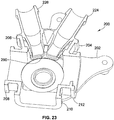
FIG. 22 is a perspective view of a seal member of the embodiment ofFIG. 20 ; and -
FIG. 23 is another cross section the embodiment ofFIG. 20 . - While the invention will be described in connection with certain preferred embodiments, there is no intent to limit it to those embodiments. On the contrary, the intent is to cover all alternatives, modifications and equivalents as included within the spirit and scope of the invention as defined by the appended claims.
- Turning now to the figures, as will be understood from the following, embodiments of a multi-port valve assembly and its associated multi-port valve are described herein. The multi-port valve advantageously overcomes existing problems in the art by presenting an overall construction with a reduced part count, a reduced number of potential leak paths, and a reduction in overall assembly time and cost.
- With particular reference now to
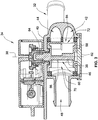
FIG. 1 , an embodiment of avalve assembly 30 according to the invention is illustrated. Thevalve assembly 30 includesvalve assembly 30 includes a multi-port valve 32 (also referred to herein as a valve) and anactuator 34 mounted tovalve 32.Actuator 34 is responsible for actuating a valve member (i.e. ashell member 58 as described below) which in turn governs the flow characteristics throughvalve 32.Actuator 34 may be any style of actuator typically used in valve actuation, e.g. rotary, linear, etc., and may rely on any type of power source typically used in valve actuation, e.g. electric, hydraulic, pneumatic, etc. As such,actuator 34 is non-limiting on the invention herein. - Turning now to
FIG. 2 ,valve assembly 30 is shown in an exploded view to introduce the componentry thereof, in particular, the componentry ofvalve 32.Valve 32 includes ahousing 40. In one advantageous implementation of the invention,housing 40 is formed as a single piece. By "formed as a single piece" it is meant that the main body ofhousing 40 and its associated ports are not an assembly of separate components which are subsequently joined together by a joining process, e.g. welding as is done in conventional valve housings. Rather,housing 40 is formed as a single unitary piece by any process capable of achieving such a configuration, e.g. injection molding, 3D printing, etc. However, it is contemplated by the teachings herein thathousing 40 may be embodied as an assembly of separate components which are subsequently joined together by a joining process. - However, there are several advantages to utilizing a
housing 40 formed as a single piece. First, such asingle piece housing 40 presents a direct reduction of parts but a retention in function over prior designs. Indeed, separate components need not be separately fabricated and subsequently assembled. Further, in such assembled housings, it is typically necessary to weld on port conduits, fittings, actuator mounting features, etc. Many of these weld joints are along the fluid flow path through the valve, and as a result, present potential leak paths in the event one or more of these welds fail. Still further, use of asingle piece housing 40 allows for direct incorporation of mounting features onhousing 40 which are subsequently used to mountvalve 32 in its operational environment. Still further, thesingle piece housing 40 illustrated allows for a single direction of assembly alonglongitudinal axis 38 defined byhousing 40. This is an improvement over prior multi-port valves which typically involve multiple directions of assembly relative to their respective housings. - As illustrated,
housing 40 includes a plurality of ports, in particular, afirst port 42, asecond port 44, athird port 46, afourth port 48, and afifth port 50, each of which are in fluid communication with aninternal cavity 56 ofhousing 40. Each ofports valve 32. As can be seen inFIG. 2 ,first port 42 andsecond port 44 are in an over/under configuration. As a result,first port 42 andsecond port 44 at least partially overlap one another in the angular direction relative tolongitudinal axis 38. As can also be seen inFIG. 2 , while overlapping one another partially in the angular direction,first port 42 andsecond port 44 are also axially spaced apart relative tolongitudinal axis 38. - Such a configuration is particularly advantageous where first and
second ports FIG. 2 ). With such a side-by-side configuration, there is a "dead zone" between the inlet ports as a result of the necessity to include a seal between the inlet ports to prevent unintended cross flow. This same seal, however, creates a dead zone which reduces the overall flow when it is desirable to combine the flows of the side-by-side inlet ports. Such a dead zone is, however, eliminated by utilizing the over/under configuration as shown. - Still referring to
FIG. 2 ,internal cavity 56 receives ashell body 58 which operates as a valve member for controlling the flows between the plurality ofports seal member 60 is also received incavity 56 and entirely surroundsshell body 58. Thisseal member 58 is a continuous cylindrical element, except for the openings formed therein. As will be discussed below,seal member 60 is a single piece seal which advantageously creates a seal for each of the plurality ofports -
Seal member 60 also advantageously entirely sealsinternal cavity 56, such that no additional seals need be associated with acover 62 ofvalve 32. It is possible, however, thatseal member 60 may also be formed as separate seal segments which immediately next to one another in the circumferential direction, which together define a seal member which surrounds theshell body 58. The term "seal member" as used herein includes both configurations, i.e. a single unitary seal member, or a seal member formed of a plurality seal segments. - As can be seen from
FIG. 2 , each ofshell body 58 andseal member 60 include a plurality of openings. The openings ofseal member 60 remain statically aligned withports housing 40 that definescavity 56, around the opening of the port intocavity 56. The plurality of openings throughshell body 58, however, are selectively alignable withports - Turning now to
FIG. 3 , which illustrates a cross section ofvalve 32 in an assembled configuration,shell body 58 is generally cylindrical in shape with avalve stem 64 which extends through an opening inhousing 40. This valve stem, and in turn the remainder ofshell body 58, is rotatable aboutaxis 38 byactuator 34.Shell body 58 also includes apartition wall 66 aligned withvalve stem 64 and dividesshell body 58 into afirst portion 70 and asecond portion 72.First portion 70 includes a first opening 74 (seeFIG. 4 ) and a second opening 76 (seeFIG. 4 ) which are separated by a wall 78 (seeFIG. 4 ). First andsecond openings shell body 58. -
Second portion 72 includes afirst opening 84, a second opening 86 (seeFIG. 7 ), and a third opening 88 (seeFIG. 4 ), each of which are in fluid communication with one another through the interior ofshell body 58. As will be understood by the following,partition wall 66 and its division ofshell body 58 into twoseparation portions valve 32. - Indeed, with particular reference to
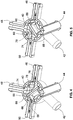
FIG. 4 , in the particular orientation ofshell body 58 shown, a combined flow from first andsecond ports second portion 72 ofshell body 58 and exits throughfifth port 50. Simultaneously, a flow fromfourth port 48 passes throughfirst portion 70 ofshell body 58 and exits throughthird port 46. Turning now toFIG. 5 ,shell body 58 has been rotated approximately ninety degrees from the orientation shown inFIG. 4 . In such a configuration a combined flow from first andsecond ports second portion 72 ofshell body 58 and exits throughthird port 46. Simultaneously, a flow fromfourth port 48 passes throughfirst portion 70 ofshell body 58 and exits throughfifth port 50. - As can be surmised from the configurations shown in
FIGS. 4 and 5 , the openings throughshell body 58 are arranged such that, for example, flow fromsecond port 44 alone, or a combined flow from first andsecond ports fifth port 50 without affecting the maximum flow fromfourth port 48 tothird port 46. The same holds true for the configuration shown inFIG. 5 in that, with only slight rotations ofshell body 58, single or combined flows from first andsecond ports fourth port 48 tofifth port 50. - Turning now to
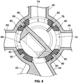
FIG. 6 , another cross section ofvalve 32 is illustrated. In this particular cross section, another advantage of utilizing aunitary seal member 60 and theshell body 58 as described can be seen. In particular, the total flow area through eachport seal member 60 are tapered to thereby continuously increase the cross sectional flow area as the flow approachesshell body 58. This increase can be seen at dimension B, which is larger than dimension A. - Such a configuration allows for
shell body 58 to present a considerably larger cross sectional flow area represented by dimension C. These tapered openings throughseal member 60 thus allow for the cross sectional flow area from eachport shell body 58. The overall result with such a configuration is a reduction in the overall pressure drop acrossvalve 32, and well as noise due to turbulence. - Also depicted in
FIG. 6 is the mounting configuration used for mountingseal member 60 withinhousing 40. Specifically,seal member 60 includes a plurality of axially extendingchannels 80 which receive a plurality of axially extendingribs 90 formed incavity 56 ofhousing 40. This channel-rib configuration fixes and clocks sealmember 60 withinhousing 40. Although eachchannel 80 andrib 90 are shown to have a uniform shape, it is also contemplated that one or more of thechannels 80 and theircorresponding ribs 90 may be a different size to ensure that there is only one way to installseal member 60 withinhousing 40. - Turning now to
FIG. 7 , the same illustratesseal member 60 installed aroundshell body 58. As introduced above,seal member 60 includes a plurality of openings. In particular, afirst opening 92, asecond opening 94, athird opening 96, afourth opening 98 which is not visible inFIG. 7 but identical tothird opening 96, and afifth opening 100 which is also not visible inFIG. 7 but identical to third andfourth openings seal member 60 are also shown inFIG. 2 . As discussed above, these openings seal around the ports ofhousing 40 at the entry of each port into cavity 56 (seeFIG. 2 ). Indeed, opening 92 seals aroundfirst port 42,second opening 94 seals aroundsecond port 94,third opening 96 seals aroundthird port 46, fourth opening 98 seals around forthport 48, andfifth opening 100 seals aroundfifth port 50. - With the foregoing structural description in hand, the flow methodology of
valve 32 will now be discussed in greater detail. Turning now toFIG. 8 , the same schematically illustrates the flows previously described relative toFIG. 4 . Flow line A may be considered to be that flow entering throughfirst port 42, and flow line B may be considered to be that flow entering throughsecond port 44. These flows are combined and exit as flow E, theflow exiting valve 32 throughfifth port 50. As discussed above, it is possible under very minor rotations ofshell body 58 to allow for only an entry flow A and an exit flow E, only an entry flow B and an exit flow E, or a mix of flows A and B which result in an exit flow E. In each of the aforementioned flow configurations, maximum entry flow D fromfourth port 48 to exit flow C throughthird port 46 is still permitted. -
FIG. 9 similarly illustrates a flow schematic whereinvalve 32 is in a neutral position, where no flow is permitted throughvalve 32.FIG. 10 schematically illustrates the flows previously described relative toFIG. 5 . As can be seen in this view, flows A and B are combined andexit valve 32 as exit flow C throughthird port 46. It is also possible under very minor rotations ofshell body 58 to allow for only an entry flow A and an exit flow C, only an entry flow B and an exit flow C, or a mix of flows A and B which result in an exit flow C. In each of the aforementioned flow configurations, maximum entry flow D fromfourth port 48 to exit flow E throughfifth port 50 is still permitted. - The aforementioned configurations are also each shown in
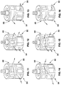
FIG. 11-16 , respectively in regard to the orientation ofshell body 58.FIG. 11 illustrates flow fromfirst port 42 throughfirst opening 84 ofsecond portion 72, throughthird opening 88 ofsecond portion 72, and out tothird port 46.FIG. 12 shows a combined flow from first andsecond ports third openings second portion 72, then through third andsecond openings third port 46.FIG. 13 illustrates flow fromsecond port 44 throughthird opening 88 ofsecond portion 72, throughsecond opening 86 ofsecond portion 72, and out tothird port 46. -
FIG. 14 illustrates flow fromsecond port 46 throughthird opening 88 ofsecond portion 72, throughfirst opening 84 of second portion, and out tofifth port 50.FIG. 15 shows a combined flow from first andsecond ports third openings second portion 72, then through third andfirst openings fifth port 50.FIG. 16 illustrates flow fromfirst port 42 throughsecond opening 86 ofsecond portion 72, throughthird opening 88 of second portion, and out tofifth port 50. It will also be recognized that, while not shown inFIGS. 11-16 for clarity, there is also a simultaneous flow in addition to that depicted in each figure. For example, there is also a flow betweenfourth port 48 andfifth port 50 in the configuration shown inFIGS. 11-13 . Similarly, there is also a flow between third andfourth ports FIGS. 14-16 . - Turning now to
FIG. 17 , an alternative embodiment of aseal member 102 is illustrated. Thisseal member 102 is similar to sealmember 60 discussed above in that it fully surroundsshell body 58. However, this embodiment of aseal member 102 includes a generallyrigid core 104 with elastomeric seal material attached thereto. More specifically, afirst seal 106,second seal 108,third seal 110, andfourth seal 112 are attached tocore 104. Theseseal members seal member 60 described above. As can also be seen inFIG. 17 ,seal member 112 is a dual port seal in that it provides the above described seal for bothfirst port 42 andsecond port 44. - With reference now to
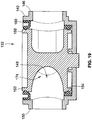
FIGS. 18 and19 , an alternative embodiment of avalve 132 according to the teachings herein is illustrated. Thisvalve 132 is also capable of the flow configurations illustrated inFIGS. 8-10 . Thisvalve 132 is also substantially similar to that described above in that may utilize ahousing 140 formed as a single piece. Thishousing 140 also includes a plurality of ports, namely, afirst port 142,second port 144,third port 146,fourth port 148, andfifth port 150. Instead of using an over/under configuration for first andsecond ports second ports second ports longitudinal axis 138. - A
shell body 158 andseal member 160 are received in aninternal cavity 156 ofhousing 140.Seal member 160 also differs fromseal member 60 described above in that it seals radially inward againstshell body 158 as shown, as opposed to radially outward as in the case ofseal member 60 andseal member 102 described above. Indeed,seal member 160 includes a plurality of receivingchannels 180 as shown. Each receivingchannel 180 receives acorresponding rib 190 formed onhousing 140 withininternal cavity 156. This channel and rib configuration fixes and clocks sealmember 160 withinhousing 140. Eachchannel 180 also includes an radially inwardly protruding sealingbead 182 as shown. These sealingbeads 182 seal againstshell body 158 to achieve similar sealing functionality to that described above. Althoughseal member 160 is illustrated a single unitary piece which surroundsshell body 158, it is also contemplated that thisseal member 160 may be separated into multiple seal segments as discussed above. In a particular configuration, and similar to that described above relative toFIG. 17 , if provided as separate seal segments, one of such seal segments can provide sealing functionality for both first andsecond ports - As can also be seen in
FIG. 18 ,shell body 158 includes apartition wall 166 which divides it into a first portion 170 and asecond portion 172. First portion 170 includes apassageway 174 extending throughshell body 158 along a curved path. Likewise,second portion 172 includes a passageway extending throughshell body 158 along a curved path. It will be recognized from analysis ofFIG. 18 that the same simultaneous flow path configurations described above relative toFIGS. 11-16 are possible with this embodiment. - Turning now to
FIG. 19 , another cross section ofvalve 132 is illustrated. As shown in this view,seal member 160 also includescircumferential seals seal member 160. Theseseals ribs 182 discussed above. - With reference now to
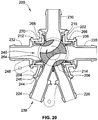
FIGS. 20 to 23 , another alternative embodiment of avalve 200 according to the teachings herein is illustrated. This embodiment ofvalve 200 is also capable of the flow configurations illustrated inFIGS. 8-10 . This embodiment ofvalve 200 also employs a side-by-side port configuration in the same arrangement as that of the embodiment described above relative toFIGS. 18 and19 . The following description, however, is not limited to the side-by-side port configuration as discussed above relative toFIGS. 18 and19 . Indeed, the following description could also apply to a valve constructed according to the teachings of the embodiment ofFIGS. 1-17 , i.e. a valve having an over-under portion configuration. - With particular reference to
FIG. 20 ,valve 200 includes ahousing 202 that includes a plurality of ports, namely, afirst port 204,second port 206,third port 208,fourth port 210, andfifth port 212. Instead of using an over/under configuration for first andsecond ports ports second ports second ports longitudinal axis 214. - A plurality of port bodies, namely, a
first port body 224, asecond port body 226, athird port body 228, afourth port body 230, and afifth port body 232 are respectively received in the first throughfifth ports port bodies first port body 224 which applies equally well to the remaining port bodies. -
First port body 224 includes a throughbore 238 which communicates with aninternal cavity 240 containing a shell body 242 rotatably disposed therein. Shell body 242 is identical to shellbody 158 described above in both structure and function, and as such, a description thereof is not repeated here. - A first radially protruding
flange 244 extends radially outwardly fromfirst port body 224. This first radially protrudingflange 244 abuts anabutment face 246 atfirst port 204 and is sealed against the same via welding, adhesion, or any other mechanical joining technology. As can be seen inFIG. 20 , eachport port body - A second radially protruding
flange 248 also extends radially fromfirst port body 224. This second radially protrudingflange 248 biases afirst seal segment 264 against shell body 242. As can be seen inFIG. 20 ,first seal segment 264 provides a seal against shell body 242 for each of first andsecond port bodies FIG. 17 . - As can be seen in
FIG. 20 , first andsecond port bodies first seal segment 264 against shell body 242. Each of first andsecond port bodies first seal segment 264 as shown until their respective second radially protruding flanges (see e.g. second radially protrudingflange 248 of first port body 224) abutsseal segment 264. - In a similar fashion, the remaining third through
fifth port bodies fourth seal member seal members ports second port bodies seal members fifth port bodies seal member - With reference now to
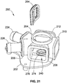
FIG. 21 ,housing 202 is illustrated with the third throughfifth port bodies housing 202. As can be seen in this view,housing 202 includes an opening 272 for reception of shell body 242 during assembly. A cover (not shown) is sealingly attached to opening 272 to seal shell body 242 withininternal cavity 240. - The aforementioned cover may be permanently affixed to
housing 202 using any mechanical joining technology, e.g. adhesives, welding, etc. Alternatively, this cover may be removably attached tohousing 202 using fasteners, threads, or the like. In the case of a removable cover, appropriate seals may also be utilized in conjunction with said cover. - Housing also includes an
aperture 274 extending through abottom wall 276 ofhousing 202. This aperture is sized to receive a valve stem (not shown) attached to shell body 242. Rotation of this valve stem results in a like rotation of shell body 242 withininternal cavity 240. As was the case with the above discussed cover, appropriate seals may be used in conjunction with the valve stem to prevent a leak path along the valve stem and out ofhousing 202. - Referring now to
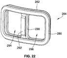
FIG. 22 ,first seal member 264 includes afirst seal flange 280 which abuts the second radially protruding flange of each of the first andsecond port bodies 224, 226 (seee.g. flange 248 inFIG. 20 ).First seal member 264 also includes asecond flange 282 which sealingly engages the outer periphery of shell body 242 (see alsoFIG. 20 ). -
First seal member 264 also includes anintermediary portion 290 dividingfirst seal member 264 into afirst seal portion 294 and asecond seal section 296.First seal section 294 is responsible for sealing the flow through first port 204 (and more particularly first port body 224) such that it may only selectively flow through shell body 242.Second seal section 296 is responsible for sealing the flow through second port 206 (and more particularly second port body 226) such that it may only selectively flow through shell body 242. -
Intermediary portion 290 provides acommon surface 292 for contact with the second radially protruding flange of each of first andsecond port bodies seal members seal member 264, except that they do not include an intermediary portion. - Despite their close proximity and despite that they share a common seal, first and
second ports respective port bodies second ports second port bodies FIG. 23 , the smaller the size of the intermediary seal portion the higher the granularity in the mixing capabilities between the first andsecond port bodies - As described herein, embodiments of the present invention The multi-port valve advantageously overcomes existing problems in the art by presenting an overall construction with a reduced part count, a reduced number of potential leak paths, and a reduction in overall assembly time and cost.
- All references, including publications, patent applications, and patents cited herein are hereby incorporated by reference to the same extent as if each reference were individually and specifically indicated to be incorporated by reference and were set forth in its entirety herein.
- The use of the terms "a" and "an" and "the" and similar referents in the context of describing the invention (especially in the context of the following claims) is to be construed to cover both the singular and the plural, unless otherwise indicated herein or clearly contradicted by context. The terms "comprising," "having," "including," and "containing" are to be construed as open-ended terms (i.e., meaning "including, but not limited to,") unless otherwise noted. Recitation of ranges of values herein are merely intended to serve as a shorthand method of referring individually to each separate value falling within the range, unless otherwise indicated herein, and each separate value is incorporated into the specification as if it were individually recited herein. All methods described herein can be performed in any suitable order unless otherwise indicated herein or otherwise clearly contradicted by context. The use of any and all examples, or exemplary language (e.g., "such as") provided herein, is intended merely to better illuminate the invention and does not pose a limitation on the scope of the invention unless otherwise claimed. No language in the specification should be construed as indicating any non-claimed element as essential to the practice of the invention.
- Preferred embodiments of this invention are described herein, including the best mode known to the inventors for carrying out the invention. Variations of those preferred embodiments may become apparent to those of ordinary skill in the art upon reading the foregoing description. The inventors expect skilled artisans to employ such variations as appropriate, and the inventors intend for the invention to be practiced otherwise than as specifically described herein. Accordingly, this invention includes all modifications and equivalents of the subject matter recited in the claims appended hereto as permitted by applicable law. Moreover, any combination of the above-described elements in all possible variations thereof is encompassed by the invention unless otherwise indicated herein or otherwise clearly contradicted by context.
- The following embodiments are also disclosed:
- 1. A multi-port valve, comprising:
- a housing defining an internal cavity, the housing further comprising a plurality of ports, wherein each of the plurality of ports is in communication with the internal cavity;
- a shell body rotatably disposed within the internal cavity; and
- a seal member having a plurality of openings and surrounding the shell body such that it circumscribes the shell body within the internal cavity.
- 2. The multi-port valve of embodiment 1, wherein each opening of the plurality of openings of the seal member is associated with one of the plurality of ports such that each of the plurality of ports are sealed from one another along the outer periphery of the seal member.
- 3. The multi-port valve of embodiment 1, wherein the plurality of ports includes a first port and a second port, wherein the first port and second port of the plurality of ports are arranged relative to one another such that they are one of:
- angularly spaced apart from one another in an angular direction and situated at a same axial height relative to a longitudinal axis of the housing; or
- in at least a partially angularly overlapped arrangement relative to one another in the angular direction and are axially spaced from one another relative to the longitudinal axis.
- 4. The multi-port valve of embodiment 1, wherein the shell body includes a partition wall separating the shell body into a first portion and a second portion, wherein the first and second portions are selectively alignable with the plurality of ports to allow simultaneous flow along a first flow path and a second flow path through the shell body.
- 5. The multi-port valve of embodiment 4, wherein the first portion includes a first opening and a second opening separated by a wall, and the second portion includes a first opening, a second opening, and a third opening.
- 6. The multi-port valve of embodiment 4, wherein the first portion includes a passageway, and the second portion includes passageway.
- 7. The multi-port valve of embodiment 4, wherein the seal member is one of a continuous piece of elastomeric material, or comprises a rigid core with a plurality of elastomeric seals attached thereto.
- 8. The multi-port valve of embodiment 1, wherein the seal member seals outwardly in a radial direction against an interior surface of the housing.
- 9. The multi-port valve of embodiment 1, wherein the seal member includes a plurality of seal ribs which seal against the shell body.
- 10. The multi-port valve of embodiment 1, further comprising a plurality of port bodies, respectively received in the plurality of ports such that one port body of the plurality of port bodies is received in one port of the plurality of ports.
- 11. The multi-port valve of embodiment 10, wherein the seal member comprises a plurality of seal segments, and wherein one of the seal segments sealingly engages a first and a second port body of the plurality of port bodies.
- 12. A multi-port valve, comprising:
- a housing defining an internal cavity, the housing further comprising a plurality of ports, wherein each of the plurality of ports is in communication with the internal cavity;
- a shell body rotatably disposed within the internal cavity; and
- a seal member having a plurality of openings, wherein each opening of the plurality of openings is associated with one of the plurality of ports such that each of the plurality of ports are sealed from one another along the outer periphery of the seal member.
- 13. The multi-port valve of embodiment 12, wherein the shell body includes a partition wall separating the shell body into a first portion and a second portion, wherein the first and second portions are selectively alignable with the plurality of ports to allow simultaneous flow along a first flow path and a second flow path through the shell body.
- 14. The multi-port valve of embodiment 13, wherein the first portion includes a first opening and a second opening separated by a wall, and the second portion includes a first opening, a second opening, and a third opening.
- 15. The multi-port valve of embodiment 13, wherein the first portion includes a passageway, and the second portion includes passageway.
- 16. The multi-port valve of embodiment 12, wherein the seal member is one of a continuous piece of elastomeric material, or comprises a rigid core with a plurality of elastomeric seals attached thereto.
- 17. The multi-port valve of embodiment 12, wherein the seal member seals outwardly in a radial direction against an interior surface of the housing.
- 18. The multi-port valve of embodiment 12, wherein the seal member includes a plurality of seal ribs which seal against the shell body.
- 19. The multi-port valve of embodiment 12, further comprising a plurality of port bodies, respectively received in the plurality of ports such that one port body of the plurality of port bodies is received in one port of the plurality of ports.
- 20. The multi-port valve of embodiment 19, wherein the seal member comprises a plurality of seal segments, and wherein one of the seal segments sealingly engages a first and a second port body of the plurality of port bodies.
- 21. A multi-port valve, comprising:
- a housing defining an internal cavity, the housing further comprising a plurality of ports, wherein a first port and a second port of the plurality of ports are arranged relative one another such that they are one of:
- angularly spaced apart from one another in an angular direction and situated at a same axial height relative to a longitudinal axis of the housing; or
- in at least a partially angularly overlapped arrangement relative to one another in the angular direction and are axially spaced from one another relative to the longitudinal axis;
- a shell body rotatably disposed within the internal cavity; and
- a seal member surrounding the shell body, the seal member radially interposed between the shell body and the housing.
- a housing defining an internal cavity, the housing further comprising a plurality of ports, wherein a first port and a second port of the plurality of ports are arranged relative one another such that they are one of:
- 22. The multi-port valve of embodiment 21, wherein the shell body includes a partition wall separating the shell body into a first portion and a second portion.
- 23. The multi-port valve of embodiment 22, wherein the first portion and second portion are selectively alignable with the plurality of ports to allow simultaneous flow along a first and a second flow path through the shell body.
- 24. The multi-port valve of embodiment 21, wherein the seal member includes a plurality of receiving grooves and the piece housing includes a plurality of projections, wherein each one of the plurality of receiving grooves receives one of the plurality of projections.
- 25. The multi-port valve of embodiment 21, further comprising a plurality of port bodies, respectively received in the plurality of ports such that one port body of the plurality of port bodies is received in one port of the plurality of ports.
- 26. The multi-port valve of embodiment 25, wherein the seal member comprises a plurality of seal segments, and wherein one of the seal segments sealingly engages a first and a second port body of the plurality of port bodies.
Claims (17)
- A multi-port valve, comprising:a housing defining an internal cavity, the housing further comprising a plurality of ports, wherein each of the plurality of ports is in communication with the internal cavity;a shell body rotatably disposed within the internal cavity; anda seal member having a plurality of openings and surrounding the shell body such that it circumscribes the shell body within the internal cavity.
- The multi-port valve of claim 1, wherein each opening of the plurality of openings of the seal member is associated with one of the plurality of ports such that each of the plurality of ports are sealed from one another along the outer periphery of the seal member.
- The multi-port valve of claim 1, wherein the plurality of ports includes a first port and a second port, wherein the first port and second port of the plurality of ports are arranged relative to one another such that they are one of:angularly spaced apart from one another in an angular direction and situated at a same axial height relative to a longitudinal axis of the housing; orin at least a partially angularly overlapped arrangement relative to one another in the angular direction and are axially spaced from one another relative to the longitudinal axis.
- The multi-port valve of claim 1, wherein the shell body includes a partition wall separating the shell body into a first portion and a second portion, wherein the first and second portions are selectively alignable with the plurality of ports to allow simultaneous flow along a first flow path and a second flow path through the shell body,
wherein optionally- the first portion includes a first opening and a second opening separated by a wall, and the second portion includes a first opening, a second opening, and a third opening; or- the first portion includes a passageway, and the second portion includes passageway; or- the seal member is one of a continuous piece of elastomeric material, or comprises a rigid core with a plurality of elastomeric seals attached thereto. - The multi-port valve of claim 1, wherein the seal member seals outwardly in a radial direction against an interior surface of the housing.
- The multi-port valve of claim 1, wherein the seal member includes a plurality of seal ribs which seal against the shell body.
- The multi-port valve of claim 1, further comprising a plurality of port bodies, respectively received in the plurality of ports such that one port body of the plurality of port bodies is received in one port of the plurality of ports,
preferably wherein the seal member comprises a plurality of seal segments, and
wherein one of the seal segments sealingly engages a first and a second port body of the plurality of port bodies. - A multi-port valve, comprising:a housing defining an internal cavity, the housing further comprising a plurality of ports, wherein each of the plurality of ports is in communication with the internal cavity;a shell body rotatably disposed within the internal cavity; anda seal member having a plurality of openings, wherein each opening of the plurality of openings is associated with one of the plurality of ports such that each of the plurality of ports are sealed from one another along the outer periphery of the seal member.
- The multi-port valve of claim 8, wherein the shell body includes a partition wall separating the shell body into a first portion and a second portion, wherein the first and second portions are selectively alignable with the plurality of ports to allow simultaneous flow along a first flow path and a second flow path through the shell body,
optionally wherein- the first portion includes a first opening and a second opening separated by a wall, and the second portion includes a first opening, a second opening, and a third opening; or- the first portion includes a passageway, and the second portion includes passageway. - The multi-port valve of claim 8, wherein the seal member is one of a continuous piece of elastomeric material, or comprises a rigid core with a plurality of elastomeric seals attached thereto.
- The multi-port valve of claim 8, wherein the seal member seals outwardly in a radial direction against an interior surface of the housing.
- The multi-port valve of claim 8, wherein the seal member includes a plurality of seal ribs which seal against the shell body.
- The multi-port valve of claim 8, further comprising a plurality of port bodies, respectively received in the plurality of ports such that one port body of the plurality of port bodies is received in one port of the plurality of ports,
preferably wherein the seal member comprises a plurality of seal segments, and
wherein one of the seal segments sealingly engages a first and a second port body of the plurality of port bodies. - A multi-port valve, comprising:a housing defining an internal cavity, the housing further comprising a plurality of ports, wherein a first port and a second port of the plurality of ports are arranged relative one another such that they are one of:angularly spaced apart from one another in an angular direction and situated at a same axial height relative to a longitudinal axis of the housing; orin at least a partially angularly overlapped arrangement relative to one another in the angular direction and are axially spaced from one another relative to the longitudinal axis;a shell body rotatably disposed within the internal cavity; anda seal member surrounding the shell body, the seal member radially interposed between the shell body and the housing.
- The multi-port valve of claim 14, wherein the shell body includes a partition wall separating the shell body into a first portion and a second portion,
preferably wherein the first portion and second portion are selectively alignable with the plurality of ports to allow simultaneous flow along a first and a second flow path through the shell body. - The multi-port valve of claim 14, wherein the seal member includes a plurality of receiving grooves and the piece housing includes a plurality of projections,
wherein each one of the plurality of receiving grooves receives one of the plurality of projections. - The multi-port valve of claim 14, further comprising a plurality of port bodies, respectively received in the plurality of ports such that one port body of the plurality of port bodies is received in one port of the plurality of ports,
preferably wherein the seal member comprises a plurality of seal segments, and wherein one of the seal segments sealingly engages a first and a second port body of the plurality of port bodies.
Applications Claiming Priority (2)
| Application Number | Priority Date | Filing Date | Title |
|---|---|---|---|
| US201762483167P | 2017-04-07 | 2017-04-07 | |
| US15/945,173 US11655905B2 (en) | 2017-04-07 | 2018-04-04 | Multi-port valve |
Publications (2)
| Publication Number | Publication Date |
|---|---|
| EP3385583A1 true EP3385583A1 (en) | 2018-10-10 |
| EP3385583B1 EP3385583B1 (en) | 2023-07-26 |
Family
ID=61911427
Family Applications (1)
| Application Number | Title | Priority Date | Filing Date |
|---|---|---|---|
| EP18165908.7A Active EP3385583B1 (en) | 2017-04-07 | 2018-04-05 | Multi-port valve |
Country Status (3)
| Country | Link |
|---|---|
| US (1) | US11655905B2 (en) |
| EP (1) | EP3385583B1 (en) |
| CN (1) | CN108692066A (en) |
Cited By (5)
| Publication number | Priority date | Publication date | Assignee | Title |
|---|---|---|---|---|
| WO2022184915A1 (en) * | 2021-03-05 | 2022-09-09 | Mack & Schneider Gmbh | Valve device |
| DE102021133871A1 (en) | 2021-12-20 | 2023-06-22 | Vr Automotive Dichtungssysteme Gmbh | METHOD OF MAKING A GASKET, GASKET AND USE OF A GASKET MADE BY SUCH METHOD |
| US11703135B2 (en) | 2021-12-03 | 2023-07-18 | Vitesco Technologies USA, LLC | Multi-port coolant flow control valve assembly |
| WO2023143165A1 (en) * | 2022-01-27 | 2023-08-03 | 安徽威灵汽车部件有限公司 | Thermal management system and vehicle having same |
| US11719350B2 (en) | 2019-06-12 | 2023-08-08 | Vitesco Technologies USA, LLC | Coolant flow control module |
Families Citing this family (18)
| Publication number | Priority date | Publication date | Assignee | Title |
|---|---|---|---|---|
| US11655905B2 (en) | 2017-04-07 | 2023-05-23 | Robertshaw Controls Company | Multi-port valve |
| US11255450B2 (en) | 2018-12-19 | 2022-02-22 | Robertshaw Controls Company | Multi-port multi-plane valve |
| DE102020201190A1 (en) * | 2019-10-14 | 2021-04-15 | Vitesco Technologies GmbH | Fluid valve |
| US11156300B2 (en) | 2019-10-30 | 2021-10-26 | Robertshaw Controls Company | Multi-port valve with partial circumferential seal arrangement |
| DE102020130486A1 (en) * | 2019-12-16 | 2021-06-17 | ECO Holding 1 GmbH | Device for handling fluid within an at least partially electrically powered vehicle |
| DE102020104615A1 (en) | 2020-02-21 | 2021-08-26 | Faurecia Autositze Gmbh | Valve device and valve system equipped therewith, as well as control device contained therein for fluid flow control |
| CN111623146A (en) * | 2020-06-01 | 2020-09-04 | 海拉(厦门)电气有限公司 | Cooling valve and cooling system |
| US11773990B2 (en) | 2020-06-05 | 2023-10-03 | Robertshaw Controls Company | Multi-port multi-mode valve |
| US11560952B2 (en) * | 2020-09-01 | 2023-01-24 | Hanon Systems | Variable cylinder wall for seals on plug valve |
| JP2023542966A (en) * | 2020-09-23 | 2023-10-12 | ボストン サイエンティフィック メディカル デバイス リミテッド | multiway connector |
| US20220235870A1 (en) * | 2021-01-26 | 2022-07-28 | Dan Knapper | Six Port Valve |
| DE102021123271A1 (en) | 2021-09-08 | 2023-03-09 | Woco Industrietechnik Gmbh | Multi-way valve, use of the multi-way valve, fluid circuit and motor vehicle |
| JP2023042855A (en) * | 2021-09-15 | 2023-03-28 | 株式会社アイシン | rotary valve |
| CN115823285A (en) * | 2021-09-16 | 2023-03-21 | 浙江三花汽车零部件有限公司 | Fluid control assembly |
| US20230220918A1 (en) * | 2022-01-13 | 2023-07-13 | Illinois Tool Works Inc. | Multi-Passage Valve |
| WO2023169651A1 (en) * | 2022-03-07 | 2023-09-14 | Johnson Electric International AG | Multi-port valve with proportional flow function |
| WO2023169648A1 (en) * | 2022-03-07 | 2023-09-14 | Johnson Electric International AG | Multi-port valve with proportional flow function |
| FR3139877A1 (en) * | 2022-09-16 | 2024-03-22 | Valeo Systemes Thermiques | Valve for at least one fluid, in particular a heat transfer liquid |
Citations (4)
| Publication number | Priority date | Publication date | Assignee | Title |
|---|---|---|---|---|
| US20060118066A1 (en) * | 2002-09-18 | 2006-06-08 | Valeo Systemes Thermiques S.A.S. | Fluid system control valve and system comprising said valve |
| EP2713083A1 (en) * | 2012-09-27 | 2014-04-02 | Systèmes Moteurs (Société par Actions Simplifiée) | Feed and control valve with rotary slide valve |
| JP2015034560A (en) * | 2013-08-07 | 2015-02-19 | 株式会社不二工機 | Seal member and channel selector valve using the same |
| EP2921750A1 (en) * | 2014-03-18 | 2015-09-23 | LK Armatur AB | A valve |
Family Cites Families (34)
| Publication number | Priority date | Publication date | Assignee | Title |
|---|---|---|---|---|
| US1422178A (en) | 1918-05-11 | 1922-07-11 | Vapor Car Heating Co Inc | Valve |
| GB270997A (en) | 1927-01-03 | 1927-05-19 | John Christopher Stead | Improvements relating to multiple way cocks or valves |
| GB905924A (en) | 1960-03-02 | 1962-09-12 | English Electric Co Ltd | Improvements in and relating to the control of the cooling water system of condensers, for example in a steam turbine plant |
| US3927693A (en) | 1974-10-11 | 1975-12-23 | Minnesota Mining & Mfg | High-pressure valve |
| US4429717A (en) | 1981-09-04 | 1984-02-07 | Montgomery Robert N | Valve for controlling the flow of semi-liquid compositions |
| US5431189A (en) | 1994-02-17 | 1995-07-11 | Jones; Ronald H. | Flow control manifold and gauge |
| US5529758A (en) | 1995-05-15 | 1996-06-25 | Houston; Reagan | Three-bed rotary valve and fume incineration system |
| US5871032A (en) | 1997-08-01 | 1999-02-16 | Chung Cheng Faucet Co., Ltd. | Diverter valve assembly for control of multiple discharge in a mixing faucet |
| US6245233B1 (en) | 1997-11-26 | 2001-06-12 | Chih Wen Lu | Water filtering apparatus with water flow switch valve device |
| US7059350B2 (en) | 2003-05-09 | 2006-06-13 | Hsin-Chi Chen | Airflow controlling mechanism |
| US7293660B2 (en) | 2004-12-22 | 2007-11-13 | Koo Chang Lin | Filter assembly having a five-way valve |
| US8881582B2 (en) | 2005-01-31 | 2014-11-11 | Waters Technologies Corporation | Method and apparatus for sample injection in liquid chromatography |
| US7506664B2 (en) | 2006-04-27 | 2009-03-24 | Ranco Incorporated Of Delaware | Automotive coolant control valve |
| US20080108955A1 (en) * | 2006-11-02 | 2008-05-08 | Blickhan Bryan J | Flow Controllers |
| US20080223464A1 (en) | 2007-03-15 | 2008-09-18 | Merrell Douglas E | Flow Diverters for Valves, Valves, and In-Floor Pool Cleaning Systems |
| US7837771B2 (en) * | 2007-10-12 | 2010-11-23 | Hamilton Sundstrand Corporation | Rotary cylinder dual diverter valve |
| FR2940396B1 (en) | 2008-12-22 | 2013-01-18 | Valeo Systemes Thermiques | FLUID SUPPLY VALVE OF A LOAD, HEAT EXCHANGER SUPPLIED BY THE VALVE, AND INTERNAL COMBUSTION THERMAL MOTOR COMPRISING THE VALVE |
| US10476051B2 (en) | 2009-04-22 | 2019-11-12 | Tesla, Inc. | Battery pack base plate heat exchanger |
| US8557416B2 (en) | 2009-04-22 | 2013-10-15 | Tesla Motors, Inc. | Battery pack directed venting system |
| US8557415B2 (en) | 2009-04-22 | 2013-10-15 | Tesla Motors, Inc. | Battery pack venting system |
| US9371921B2 (en) | 2009-06-23 | 2016-06-21 | Nordson Corporation | Multi-port valve |
| US8336319B2 (en) | 2010-06-04 | 2012-12-25 | Tesla Motors, Inc. | Thermal management system with dual mode coolant loops |
| SE535882C2 (en) | 2011-10-10 | 2013-01-29 | Micael Toernblom | Valve for administering a variety of drug fluids |
| US20140053931A1 (en) | 2012-08-23 | 2014-02-27 | Nordson, Inc. | Multiple port stopcock valve |
| US9212751B2 (en) | 2012-09-28 | 2015-12-15 | Robertshaw Controls Company | Valve system and method |
| US9321362B2 (en) | 2014-02-05 | 2016-04-26 | Tesia Motors, Inc. | Cooling of charging cable |
| US9527403B2 (en) | 2014-04-29 | 2016-12-27 | Tesla Motors, Inc. | Charging station providing thermal conditioning of electric vehicle during charging session |
| JP6351352B2 (en) * | 2014-04-30 | 2018-07-04 | 株式会社不二工機 | Flow path switching valve |
| US9803760B2 (en) | 2014-06-05 | 2017-10-31 | Schaeffler Technologies AG & Co. KG | Rotary valve with an isolating distribution body |
| US9865852B2 (en) | 2015-06-25 | 2018-01-09 | Tesla, Inc. | Energy storage container with vortex separator |
| US9687769B2 (en) | 2015-08-26 | 2017-06-27 | Tesla, Inc. | Vehicle air system with high efficiency filter |
| US10344877B2 (en) | 2015-12-01 | 2019-07-09 | Tesla Motors, Inc. | Multi-port valve with multiple operation modes |
| US10464397B2 (en) | 2016-03-03 | 2019-11-05 | Tesla, Inc. | Thermal system with high aspect ratio vent |
| US11655905B2 (en) | 2017-04-07 | 2023-05-23 | Robertshaw Controls Company | Multi-port valve |
-
2018
- 2018-04-04 US US15/945,173 patent/US11655905B2/en active Active
- 2018-04-05 EP EP18165908.7A patent/EP3385583B1/en active Active
- 2018-04-08 CN CN201810307667.4A patent/CN108692066A/en active Pending
Patent Citations (4)
| Publication number | Priority date | Publication date | Assignee | Title |
|---|---|---|---|---|
| US20060118066A1 (en) * | 2002-09-18 | 2006-06-08 | Valeo Systemes Thermiques S.A.S. | Fluid system control valve and system comprising said valve |
| EP2713083A1 (en) * | 2012-09-27 | 2014-04-02 | Systèmes Moteurs (Société par Actions Simplifiée) | Feed and control valve with rotary slide valve |
| JP2015034560A (en) * | 2013-08-07 | 2015-02-19 | 株式会社不二工機 | Seal member and channel selector valve using the same |
| EP2921750A1 (en) * | 2014-03-18 | 2015-09-23 | LK Armatur AB | A valve |
Cited By (6)
| Publication number | Priority date | Publication date | Assignee | Title |
|---|---|---|---|---|
| US11719350B2 (en) | 2019-06-12 | 2023-08-08 | Vitesco Technologies USA, LLC | Coolant flow control module |
| WO2022184915A1 (en) * | 2021-03-05 | 2022-09-09 | Mack & Schneider Gmbh | Valve device |
| US11703135B2 (en) | 2021-12-03 | 2023-07-18 | Vitesco Technologies USA, LLC | Multi-port coolant flow control valve assembly |
| DE102021133871A1 (en) | 2021-12-20 | 2023-06-22 | Vr Automotive Dichtungssysteme Gmbh | METHOD OF MAKING A GASKET, GASKET AND USE OF A GASKET MADE BY SUCH METHOD |
| WO2023117706A1 (en) | 2021-12-20 | 2023-06-29 | Vr Automotive Dichtungssysteme Gmbh | Method for producing a sealing element, sealing element and use of a sealing element produced according to such a method |
| WO2023143165A1 (en) * | 2022-01-27 | 2023-08-03 | 安徽威灵汽车部件有限公司 | Thermal management system and vehicle having same |
Also Published As
| Publication number | Publication date |
|---|---|
| US20180292016A1 (en) | 2018-10-11 |
| US11655905B2 (en) | 2023-05-23 |
| CN108692066A (en) | 2018-10-23 |
| EP3385583B1 (en) | 2023-07-26 |
Similar Documents
| Publication | Publication Date | Title |
|---|---|---|
| EP3385583B1 (en) | Multi-port valve | |
| US11655906B2 (en) | Multi-port multi-plane valve | |
| US11773990B2 (en) | Multi-port multi-mode valve | |
| JP6511427B2 (en) | Flow path switching valve | |
| US11156300B2 (en) | Multi-port valve with partial circumferential seal arrangement | |
| US20200173569A1 (en) | Integrated flow check for water/coolant valves | |
| JP2021067366A (en) | valve | |
| US10138619B2 (en) | Universal embedded system for sanitary faucet components | |
| CN215928493U (en) | Control valve | |
| US7343882B2 (en) | Fluid valve | |
| KR20160079649A (en) | Channel switch valve | |
| US5911243A (en) | Multiport conversion system for butterfly valve | |
| EP1104519B1 (en) | Ball valve | |
| JP6399860B2 (en) | Flow path switching valve | |
| JP2019066007A (en) | Valve device | |
| US11649903B2 (en) | Modular valve assembly | |
| US11592116B2 (en) | Five port valve | |
| US20230279954A1 (en) | Coolant flow control valve seal assembly | |
| CN219345577U (en) | Multi-way valve | |
| WO2023190841A1 (en) | Ball screw device | |
| US7066445B1 (en) | Control valve having closely sealing effect | |
| WO2024063071A1 (en) | Flow-path switching device | |
| JPH0151712B2 (en) | ||
| JP2023042855A (en) | rotary valve | |
| CN115523321A (en) | Control valve |
Legal Events
| Date | Code | Title | Description |
|---|---|---|---|
| PUAI | Public reference made under article 153(3) epc to a published international application that has entered the european phase |
Free format text: ORIGINAL CODE: 0009012 |
|
| STAA | Information on the status of an ep patent application or granted ep patent |
Free format text: STATUS: THE APPLICATION HAS BEEN PUBLISHED |
|
| AK | Designated contracting states |
Kind code of ref document: A1 Designated state(s): AL AT BE BG CH CY CZ DE DK EE ES FI FR GB GR HR HU IE IS IT LI LT LU LV MC MK MT NL NO PL PT RO RS SE SI SK SM TR |
|
| AX | Request for extension of the european patent |
Extension state: BA ME |
|
| STAA | Information on the status of an ep patent application or granted ep patent |
Free format text: STATUS: REQUEST FOR EXAMINATION WAS MADE |
|
| 17P | Request for examination filed |
Effective date: 20190408 |
|
| RBV | Designated contracting states (corrected) |
Designated state(s): AL AT BE BG CH CY CZ DE DK EE ES FI FR GB GR HR HU IE IS IT LI LT LU LV MC MK MT NL NO PL PT RO RS SE SI SK SM TR |
|
| STAA | Information on the status of an ep patent application or granted ep patent |
Free format text: STATUS: EXAMINATION IS IN PROGRESS |
|
| 17Q | First examination report despatched |
Effective date: 20190802 |
|
| STAA | Information on the status of an ep patent application or granted ep patent |
Free format text: STATUS: EXAMINATION IS IN PROGRESS |
|
| STAA | Information on the status of an ep patent application or granted ep patent |
Free format text: STATUS: EXAMINATION IS IN PROGRESS |
|
| GRAP | Despatch of communication of intention to grant a patent |
Free format text: ORIGINAL CODE: EPIDOSNIGR1 |
|
| STAA | Information on the status of an ep patent application or granted ep patent |
Free format text: STATUS: GRANT OF PATENT IS INTENDED |
|
| INTG | Intention to grant announced |
Effective date: 20221019 |
|
| GRAS | Grant fee paid |
Free format text: ORIGINAL CODE: EPIDOSNIGR3 |
|
| GRAA | (expected) grant |
Free format text: ORIGINAL CODE: 0009210 |
|
| STAA | Information on the status of an ep patent application or granted ep patent |
Free format text: STATUS: THE PATENT HAS BEEN GRANTED |
|
| AK | Designated contracting states |
Kind code of ref document: B1 Designated state(s): AL AT BE BG CH CY CZ DE DK EE ES FI FR GB GR HR HU IE IS IT LI LT LU LV MC MK MT NL NO PL PT RO RS SE SI SK SM TR |
|
| REG | Reference to a national code |
Ref country code: CH Ref legal event code: EP |
|
| REG | Reference to a national code |
Ref country code: IE Ref legal event code: FG4D |
|
| REG | Reference to a national code |
Ref country code: DE Ref legal event code: R096 Ref document number: 602018053920 Country of ref document: DE |
|
| REG | Reference to a national code |
Ref country code: LT Ref legal event code: MG9D |
|
| REG | Reference to a national code |
Ref country code: NL Ref legal event code: MP Effective date: 20230726 |
|
| REG | Reference to a national code |
Ref country code: AT Ref legal event code: MK05 Ref document number: 1592254 Country of ref document: AT Kind code of ref document: T Effective date: 20230726 |
|
| PG25 | Lapsed in a contracting state [announced via postgrant information from national office to epo] |
Ref country code: NL Free format text: LAPSE BECAUSE OF FAILURE TO SUBMIT A TRANSLATION OF THE DESCRIPTION OR TO PAY THE FEE WITHIN THE PRESCRIBED TIME-LIMIT Effective date: 20230726 |
|
| PG25 | Lapsed in a contracting state [announced via postgrant information from national office to epo] |
Ref country code: GR Free format text: LAPSE BECAUSE OF FAILURE TO SUBMIT A TRANSLATION OF THE DESCRIPTION OR TO PAY THE FEE WITHIN THE PRESCRIBED TIME-LIMIT Effective date: 20231027 |
|
| PG25 | Lapsed in a contracting state [announced via postgrant information from national office to epo] |
Ref country code: IS Free format text: LAPSE BECAUSE OF FAILURE TO SUBMIT A TRANSLATION OF THE DESCRIPTION OR TO PAY THE FEE WITHIN THE PRESCRIBED TIME-LIMIT Effective date: 20231126 |
|
| PG25 | Lapsed in a contracting state [announced via postgrant information from national office to epo] |
Ref country code: SE Free format text: LAPSE BECAUSE OF FAILURE TO SUBMIT A TRANSLATION OF THE DESCRIPTION OR TO PAY THE FEE WITHIN THE PRESCRIBED TIME-LIMIT Effective date: 20230726 Ref country code: RS Free format text: LAPSE BECAUSE OF FAILURE TO SUBMIT A TRANSLATION OF THE DESCRIPTION OR TO PAY THE FEE WITHIN THE PRESCRIBED TIME-LIMIT Effective date: 20230726 Ref country code: PT Free format text: LAPSE BECAUSE OF FAILURE TO SUBMIT A TRANSLATION OF THE DESCRIPTION OR TO PAY THE FEE WITHIN THE PRESCRIBED TIME-LIMIT Effective date: 20231127 Ref country code: NO Free format text: LAPSE BECAUSE OF FAILURE TO SUBMIT A TRANSLATION OF THE DESCRIPTION OR TO PAY THE FEE WITHIN THE PRESCRIBED TIME-LIMIT Effective date: 20231026 Ref country code: LV Free format text: LAPSE BECAUSE OF FAILURE TO SUBMIT A TRANSLATION OF THE DESCRIPTION OR TO PAY THE FEE WITHIN THE PRESCRIBED TIME-LIMIT Effective date: 20230726 Ref country code: LT Free format text: LAPSE BECAUSE OF FAILURE TO SUBMIT A TRANSLATION OF THE DESCRIPTION OR TO PAY THE FEE WITHIN THE PRESCRIBED TIME-LIMIT Effective date: 20230726 Ref country code: IS Free format text: LAPSE BECAUSE OF FAILURE TO SUBMIT A TRANSLATION OF THE DESCRIPTION OR TO PAY THE FEE WITHIN THE PRESCRIBED TIME-LIMIT Effective date: 20231126 Ref country code: HR Free format text: LAPSE BECAUSE OF FAILURE TO SUBMIT A TRANSLATION OF THE DESCRIPTION OR TO PAY THE FEE WITHIN THE PRESCRIBED TIME-LIMIT Effective date: 20230726 Ref country code: GR Free format text: LAPSE BECAUSE OF FAILURE TO SUBMIT A TRANSLATION OF THE DESCRIPTION OR TO PAY THE FEE WITHIN THE PRESCRIBED TIME-LIMIT Effective date: 20231027 Ref country code: FI Free format text: LAPSE BECAUSE OF FAILURE TO SUBMIT A TRANSLATION OF THE DESCRIPTION OR TO PAY THE FEE WITHIN THE PRESCRIBED TIME-LIMIT Effective date: 20230726 Ref country code: AT Free format text: LAPSE BECAUSE OF FAILURE TO SUBMIT A TRANSLATION OF THE DESCRIPTION OR TO PAY THE FEE WITHIN THE PRESCRIBED TIME-LIMIT Effective date: 20230726 |
|
| PG25 | Lapsed in a contracting state [announced via postgrant information from national office to epo] |
Ref country code: PL Free format text: LAPSE BECAUSE OF FAILURE TO SUBMIT A TRANSLATION OF THE DESCRIPTION OR TO PAY THE FEE WITHIN THE PRESCRIBED TIME-LIMIT Effective date: 20230726 |
|
| PG25 | Lapsed in a contracting state [announced via postgrant information from national office to epo] |
Ref country code: ES Free format text: LAPSE BECAUSE OF FAILURE TO SUBMIT A TRANSLATION OF THE DESCRIPTION OR TO PAY THE FEE WITHIN THE PRESCRIBED TIME-LIMIT Effective date: 20230726 |
|
| PG25 | Lapsed in a contracting state [announced via postgrant information from national office to epo] |
Ref country code: SM Free format text: LAPSE BECAUSE OF FAILURE TO SUBMIT A TRANSLATION OF THE DESCRIPTION OR TO PAY THE FEE WITHIN THE PRESCRIBED TIME-LIMIT Effective date: 20230726 Ref country code: RO Free format text: LAPSE BECAUSE OF FAILURE TO SUBMIT A TRANSLATION OF THE DESCRIPTION OR TO PAY THE FEE WITHIN THE PRESCRIBED TIME-LIMIT Effective date: 20230726 Ref country code: ES Free format text: LAPSE BECAUSE OF FAILURE TO SUBMIT A TRANSLATION OF THE DESCRIPTION OR TO PAY THE FEE WITHIN THE PRESCRIBED TIME-LIMIT Effective date: 20230726 Ref country code: EE Free format text: LAPSE BECAUSE OF FAILURE TO SUBMIT A TRANSLATION OF THE DESCRIPTION OR TO PAY THE FEE WITHIN THE PRESCRIBED TIME-LIMIT Effective date: 20230726 Ref country code: DK Free format text: LAPSE BECAUSE OF FAILURE TO SUBMIT A TRANSLATION OF THE DESCRIPTION OR TO PAY THE FEE WITHIN THE PRESCRIBED TIME-LIMIT Effective date: 20230726 Ref country code: CZ Free format text: LAPSE BECAUSE OF FAILURE TO SUBMIT A TRANSLATION OF THE DESCRIPTION OR TO PAY THE FEE WITHIN THE PRESCRIBED TIME-LIMIT Effective date: 20230726 Ref country code: SK Free format text: LAPSE BECAUSE OF FAILURE TO SUBMIT A TRANSLATION OF THE DESCRIPTION OR TO PAY THE FEE WITHIN THE PRESCRIBED TIME-LIMIT Effective date: 20230726 |