EP3385486A1 - Transparent panel - Google Patents
Transparent panel Download PDFInfo
- Publication number
- EP3385486A1 EP3385486A1 EP17179030.6A EP17179030A EP3385486A1 EP 3385486 A1 EP3385486 A1 EP 3385486A1 EP 17179030 A EP17179030 A EP 17179030A EP 3385486 A1 EP3385486 A1 EP 3385486A1
- Authority
- EP
- European Patent Office
- Prior art keywords
- profiles
- glass sheets
- panel
- frame
- transparent
- Prior art date
- Legal status (The legal status is an assumption and is not a legal conclusion. Google has not performed a legal analysis and makes no representation as to the accuracy of the status listed.)
- Granted
Links
- 239000011521 glass Substances 0.000 claims abstract description 78
- 239000000463 material Substances 0.000 claims abstract description 11
- 229920003023 plastic Polymers 0.000 claims abstract description 7
- 239000004033 plastic Substances 0.000 claims abstract description 5
- 239000003292 glue Substances 0.000 claims description 22
- 150000003839 salts Chemical class 0.000 claims description 9
- 238000000034 method Methods 0.000 claims description 6
- 239000004417 polycarbonate Substances 0.000 claims description 5
- 229920000515 polycarbonate Polymers 0.000 claims description 4
- JOYRKODLDBILNP-UHFFFAOYSA-N Ethyl urethane Chemical compound CCOC(N)=O JOYRKODLDBILNP-UHFFFAOYSA-N 0.000 claims description 3
- 125000005395 methacrylic acid group Chemical group 0.000 claims description 3
- 238000000465 moulding Methods 0.000 claims description 3
- 238000007711 solidification Methods 0.000 claims description 3
- 230000008023 solidification Effects 0.000 claims description 3
- 238000004026 adhesive bonding Methods 0.000 claims description 2
- 239000000565 sealant Substances 0.000 claims description 2
- 229910052751 metal Inorganic materials 0.000 description 11
- 239000002184 metal Substances 0.000 description 11
- 239000000853 adhesive Substances 0.000 description 8
- 230000001070 adhesive effect Effects 0.000 description 8
- 239000007789 gas Substances 0.000 description 5
- 238000004873 anchoring Methods 0.000 description 3
- 230000008878 coupling Effects 0.000 description 3
- 238000010168 coupling process Methods 0.000 description 3
- 238000005859 coupling reaction Methods 0.000 description 3
- 238000001125 extrusion Methods 0.000 description 3
- XKRFYHLGVUSROY-UHFFFAOYSA-N Argon Chemical compound [Ar] XKRFYHLGVUSROY-UHFFFAOYSA-N 0.000 description 2
- 238000009833 condensation Methods 0.000 description 2
- 230000005494 condensation Effects 0.000 description 2
- 238000007598 dipping method Methods 0.000 description 2
- 238000009413 insulation Methods 0.000 description 2
- 239000010410 layer Substances 0.000 description 2
- 238000006124 Pilkington process Methods 0.000 description 1
- 239000012790 adhesive layer Substances 0.000 description 1
- 239000004411 aluminium Substances 0.000 description 1
- 229910052782 aluminium Inorganic materials 0.000 description 1
- XAGFODPZIPBFFR-UHFFFAOYSA-N aluminium Chemical compound [Al] XAGFODPZIPBFFR-UHFFFAOYSA-N 0.000 description 1
- 229910052786 argon Inorganic materials 0.000 description 1
- 230000005540 biological transmission Effects 0.000 description 1
- 230000000694 effects Effects 0.000 description 1
- 235000013305 food Nutrition 0.000 description 1
- 230000003116 impacting effect Effects 0.000 description 1
- 238000003780 insertion Methods 0.000 description 1
- 230000037431 insertion Effects 0.000 description 1
- UQSXHKLRYXJYBZ-UHFFFAOYSA-N iron oxide Inorganic materials [Fe]=O UQSXHKLRYXJYBZ-UHFFFAOYSA-N 0.000 description 1
- 235000013980 iron oxide Nutrition 0.000 description 1
- VBMVTYDPPZVILR-UHFFFAOYSA-N iron(2+);oxygen(2-) Chemical class [O-2].[Fe+2] VBMVTYDPPZVILR-UHFFFAOYSA-N 0.000 description 1
- 238000005304 joining Methods 0.000 description 1
- 239000007791 liquid phase Substances 0.000 description 1
- 238000004519 manufacturing process Methods 0.000 description 1
- 229910052756 noble gas Inorganic materials 0.000 description 1
- 150000002835 noble gases Chemical class 0.000 description 1
- 238000005192 partition Methods 0.000 description 1
- 238000006116 polymerization reaction Methods 0.000 description 1
- 230000002787 reinforcement Effects 0.000 description 1
- 230000003014 reinforcing effect Effects 0.000 description 1
- 238000007789 sealing Methods 0.000 description 1
- 239000007787 solid Substances 0.000 description 1
- 125000006850 spacer group Chemical group 0.000 description 1
- 238000002834 transmittance Methods 0.000 description 1
- 239000012780 transparent material Substances 0.000 description 1
- 239000002699 waste material Substances 0.000 description 1
Images

Classifications
-
- E—FIXED CONSTRUCTIONS
- E06—DOORS, WINDOWS, SHUTTERS, OR ROLLER BLINDS IN GENERAL; LADDERS
- E06B—FIXED OR MOVABLE CLOSURES FOR OPENINGS IN BUILDINGS, VEHICLES, FENCES OR LIKE ENCLOSURES IN GENERAL, e.g. DOORS, WINDOWS, BLINDS, GATES
- E06B3/00—Window sashes, door leaves, or like elements for closing wall or like openings; Layout of fixed or moving closures, e.g. windows in wall or like openings; Features of rigidly-mounted outer frames relating to the mounting of wing frames
- E06B3/66—Units comprising two or more parallel glass or like panes permanently secured together
- E06B3/663—Elements for spacing panes
- E06B3/66309—Section members positioned at the edges of the glazing unit
- E06B3/66333—Section members positioned at the edges of the glazing unit of unusual substances, e.g. wood or other fibrous materials, glass or other transparent materials
- E06B2003/66338—Section members positioned at the edges of the glazing unit of unusual substances, e.g. wood or other fibrous materials, glass or other transparent materials of glass
-
- E—FIXED CONSTRUCTIONS
- E06—DOORS, WINDOWS, SHUTTERS, OR ROLLER BLINDS IN GENERAL; LADDERS
- E06B—FIXED OR MOVABLE CLOSURES FOR OPENINGS IN BUILDINGS, VEHICLES, FENCES OR LIKE ENCLOSURES IN GENERAL, e.g. DOORS, WINDOWS, BLINDS, GATES
- E06B3/00—Window sashes, door leaves, or like elements for closing wall or like openings; Layout of fixed or moving closures, e.g. windows in wall or like openings; Features of rigidly-mounted outer frames relating to the mounting of wing frames
- E06B3/02—Wings made completely of glass
- E06B3/025—Wings made completely of glass consisting of multiple glazing units
Definitions
- Object of the present invention is a transparent panel intended for being used as access door for fridges or showcases, or as partition wall of showcases and displays.
- the transparent doors are further used also for showcases and exposition cabinets, such as the displays.
- double-glazing type also named double layer glass type: at least two glass sheets are coupled to a frame such to remain parallel and to define an interstice therebetween, filled with air or noble gases and acting as heat insulating.
- the frame develops along the perimeter of the glass sheets, as a frame.
- the frame is made of metal sections, for example made of aluminium, and the glass sheets are air-tight glued to such sections. Hinges and fitting needed to allow to serve as a door, for example pivots, are mounted on the frame.
- EP-B-2878233 describes a transparent panel obtained by coupling one to another at least two (transparent) glass sheets only by means of a glue that is itself transparent after the respective setting.
- the glue is applied at the edge of the sheets and, once hardened, constitutes a connecting element and at the same time ensures air tightness, i.e. preserves the insulating effect of the double-glazing. If needed, metal reinforcements are inserted in the panel at the corners.
- the glue application technique is also described.
- the glass sheets to be coupled are kept parallel, at a distance corresponding to the interstice to be created between the sheets, and they are partially dipped in a vessel containing the liquid phase glue.
- the sheet dipping is provided at the respective edges.
- the glue is let solidify, for example by UV or hot air polymerization, and this operation takes long time; the sheets are then extracted from the vessel and rotated in order to repeat the operation for all sides, until the perimeter has been completed.
- Object of the present invention is therefore to provide a completely transparent panel, made by a technique easier than that described in EP-B-2878233 and with lower costs.
- the present invention has the aim of providing a double-glazing panel that is transparent at the edges also, i.e. at the frame, while being easy to implement with low costs and in short times.
- the present invention relates therefore to a double-glazing panel comprising at least two glass sheets and one perimetrical frame, i.e. a frame extending along the perimeter of the glass sheets.
- the glass sheets are supported parallel to one another only by the frame, thus the latter constituting a structural as well as an aesthetic element.
- a chamber containing air or gas, sealingly isolated from the outside, is defined between the adjacent glass sheets and the frame.
- the frame consists of one or more profiles directly glued to the glass sheets, just at the respective edges.
- At least one of the profiles is transparent and preferably most of the frame, or all, is transparent.
- the proposed solution allows obtaining the pleasant aesthetic result described in relation to the known art, but without incurring in the related drawbacks.
- the transparent profiles are not constituted by glue that is transparent when solidified, as provided in EP-B-2878233 ; therefore, the panel assembly is much easier, the final result being the same.
- the profiles can be made separately before the panel assembly, with very low costs.
- the profiles are made of a plastic material, for example polycarbonate.
- the profiles are extruded, even if alternatively, they can be obtained by the moulding technique.
- the glass sheets are rectangular or square.
- the profiles are four, a left vertical profile, a right vertical profile, a top horizontal profile and a bottom horizontal profile.
- Each one of the profiles is glued to at least two glass sheets, so as to also act as spacer in order to obtain the inner chamber, or to all the glass sheets (one profile per each panel edge) if these are more than two, at the respective edges.
- At least one of the vertical profiles is transparent, and preferably both the right and left vertical profiles are transparent.
- the remaining profiles, the top and the bottom ones, can be transparent or not.
- the two chambers would be however limited by the sheets and the frame profiles.
- two profiles could be used per each panel edge: a profile for connecting the first glass sheet with the second glass sheet and another profile for connecting the second glass sheet with the third glass sheet.
- the transparent profiles have T-shaped cross section.
- the glass sheets are glued to the profiles at the longitudinal portion of the T shape, at opposite sides, and in abutment against the transversal portion of the T shape.
- the glass sheets are preferably glued to the transparent profiles so as to be flush with the profiles themselves, i.e. in such a way to create a single panel with seamless outer surfaces, free from slots or undercuts.
- the glass sheets are glued to the transparent profiles by means of a transparent glue.
- the glue also acts as sealant of the chamber containing air or gases.
- At least one of the profiles comprises a first inner seat in which dehydrating salts are housed.
- Salts have the task of absorbing humidity from the inner chamber, to prevent condensation from forming on the glass sheets. It is a real risk, mostly if the panel is used as fridge door.
- the profiles provided with the housing seat for dehydrating salts are the top profile and the bottom profile, that can also be not transparent and, thus, can hide salts.
- Another optional feature of the panel for which the Applicant reserves the right to deposit a divisional Patent Application, consists in that at least one of the profiles, and preferably the two bottom and top profiles, comprises a second inner seat in which a bar is housed.
- the bar has a double function:
- the bars are flat, i.e. they are battens and extend for the whole length of the edge of the respective glass sheets.
- a second aspect of the present invention relates to a method for making a double-glazing panel, for the use as door or window, comprising:
- FIG. 1 frontally and schematically shows a refrigerator 1 of the type used in supermarkets for selling fresh, frozen or deep-frozen foods.
- the refrigerator 1 is provided with four transparent doors 2 hinged openable by holding an appropriate handle.
- Figure 2 shows a single panel 2.
- the frame 3 of the panels used as refrigerator doors is matt, since consisting of a metal frame; in the panel 2, instead, the frame 3, i.e. the panel perimeter, is at least partly transparent.
- Figures 3-5 allow explaining how this result is obtained.
- Figure 3 is an exploded front view and figures 4 and 5 are cross sectional views taken respectively on the horizontal H-H and vertical V-V planes. The views are not to scale, for greater clarity.
- a glass sheet is denoted.
- a second glass sheet 5 is denoted.
- a double glazing 6 is defined, i.e. a chamber in which air is confined or a gas is confined, for example argon, in order to maximize the thermal insulation, i.e. to reduce the transmittance of the door 2 and to limit the BTU loss from the refrigerator.
- the glass sheet 4 the outer one with respect to the refrigerator, is obtained by float process and stands out for a low content of iron oxides.
- the glass sheets are screen-printed or otherwise customized with stickers, for providing the users with indications or simple commercial information.
- the panel 2 according to the present invention provides the use of a plurality of profiles 7-10, some of which 7-8, or all of them, being transparent.
- the side profiles 7-8 are made of a transparent material, preferably polycarbonate PC, and are glued to the glass sheets 4, 5.
- the top and bottom profiles 9, 10 can be made of metal or a plastic material, for example still in polycarbonate, and in this instance, they can be transparent or not.
- the profiles 7-10 are extruded. This way, seats can be obtained in the profiles 7-10, as it will be explained later, during the extrusion step already.
- the profiles 7-10 can be moulded.
- the profiles 7-10 are slightly flexible and not completely stiff as the conventional metal profiles. This feature allows the assembly of the panel 2 to be facilitated, as it will be clear from the following description.
- the panels 2 can be assembled in the following way.
- the glass 4 is placed in a properly made mask (not shown); then a layer C of transparent high-strength adhesive material is cold spread, at the edges of the glass sheet 4, where the coupling with the profiles 7-10 is provided. Then the two top 9 and bottom 10 profiles are positioned (horizontal profiles of the panel 2), and the two left 7 and right 8 side profiles (vertical profiles of the panel 2) are positioned at the edges of the sheet 4 where the adhesive material C has been spread.
- the profiles 7-10 have a substantially T-shaped cross section and this allows obtaining a good shape coupling with the glass sheets 4 and 5.
- the edges of the sheet complementarily abut against the sides 11 of the profiles, and in such a way that the surfaces of the sheet 4 and the profiles 7-10 remain flush.
- the vertical profiles 7 and 8 can also have a rounded cross section.
- the panel 2 takes thus the shape shown in figures.
- the adhesive C also has the sealing function for the double glazing 6, meaning that, besides bonding the glass sheets 4, 5 and the profiles 7-10, it ensures the seal and, thus, the air or gas confinement in the chamber 6.
- An adhesive material suitable for this purpose is commercialized by the Loxeal Company with the code UV3021 ; it is a methacrylic urethane adhesive.
- the panel 2 has greatly pleasant aesthetic.
- the observer gets the impression that the panel 2 is free from any frame, in contrast with the impression given by conventional panels made with not-transparent metal profiles.
- Substantially the profiles 7-10 do define a frame but this is partially, or completely, also transparent as the glass sheets.
- the top 9 and bottom 10 profiles each have an inner seat 13 for housing dehydrating salts, i.e. humidity absorbing salts. Salt presence minimizes the risk of condensation to be produced in the double glazing 6.
- the seat 13 can be easily done simultaneously with the extrusion, i.e. the seat 13 can be done without material removal. Therefore, preferably, the seats 13 extend for the whole length of the profiles 9, 10.
- top 9 and bottom 10 profiles are provided with a further seat 14 extending parallel to the salt containing seat 13.
- each seat 14 a metal bar 15 is inserted with no, or minimum, clearance, having the function of providing an effective anchoring point for the fitting (not shown) intended for supporting the panel 2 as a door.
- the bars 15 are not to scale.
- the bars 15 are battens i.e. they are flat; for example, they have a thickness of about 3 mm.
- the bars have the further function of reinforcing the panel 2 and reducing the risks it can break due to excessive flexing or twisting of the glass sheets 4, 5 caused in its turn by an improper use by the user. More in detail, even if the user opened the fridge door 1 with excessive strength, i.e. violently pushed the panel 2 up to the stop, the same panel would be less at risk of breakage with respect to what can be easily found now with the solutions conventionally available on the market. Flexing and/or twisting forces produced due to the violent deceleration of the panel 2 at the stop, when the hinges can not rotate further, are largely absorbed by the metal bars 15 to whom the hinges are connected.
- the bars 15 inserted in the seats 14 also act as limiters of the wraps the panel 2 would be subjected to by violently impacting an obstacle or getting quickly to the stop.
- the Applicant found that the proposed solution greatly reduces the risk of breakage of the fridge doors, with respect to conventional solutions free from bars 15.
- the bars 15, which can also be defined as “tension bars”, are perforated, i.e. have a series of through holes along all the respective extent. In addition to reduce the weight, the holes (not shown) make more flexible the bars 15.
- plugs 16 for example extruded or moulded plugs.
- the plugs 16 can also be angular plugs.
- the panel 2 can also be made with no seats 13, the latter being preferred but optional.
- the number of glass sheets is two.
- the panel 2 according to the present invention can be made with a larger number of glass sheets, for example three, with double glazing 6.
- the frame 3 could not only be done of transparent profiles 7-10.
- one of the profiles, the bottom one 10 and/or the top one 9, could be made of metal or plastic but matt, otherwise they can be coated with an adhesive concealing the bars 15.
- the profiles 7-10 would have different shape, for example a substantially double-T-shaped cross section, such that a single profile can be used for joining all the three glass sheets, i.e. each profile is shared for constraining all the glass sheets.
Abstract
Description
- Object of the present invention is a transparent panel intended for being used as access door for fridges or showcases, or as partition wall of showcases and displays.
- More and more often fridges installed in supermarkets for selling frozen or deep-frozen products have substantially transparent doors, that allow clients seeing the products inside the fridge and, thus, allow a product to be selected before opening the door. This way, buyers are prevented from unnecessarily opening fridge doors, looking for the desired product, with subsequent energy waste.
- The transparent doors are further used also for showcases and exposition cabinets, such as the displays.
- Usually transparent doors for fridges are of the double-glazing type, also named double layer glass type: at least two glass sheets are coupled to a frame such to remain parallel and to define an interstice therebetween, filled with air or noble gases and acting as heat insulating.
- The frame develops along the perimeter of the glass sheets, as a frame. Conventionally the frame is made of metal sections, for example made of aluminium, and the glass sheets are air-tight glued to such sections. Hinges and fitting needed to allow to serve as a door, for example pivots, are mounted on the frame.
- Recently an aesthetically valuable solution has been presented, that does not provide the use of the frame.
-
EP-B-2878233 describes a transparent panel obtained by coupling one to another at least two (transparent) glass sheets only by means of a glue that is itself transparent after the respective setting. The glue is applied at the edge of the sheets and, once hardened, constitutes a connecting element and at the same time ensures air tightness, i.e. preserves the insulating effect of the double-glazing. If needed, metal reinforcements are inserted in the panel at the corners. - In
EP-B-2878233 the glue application technique is also described. At the beginning the glass sheets to be coupled are kept parallel, at a distance corresponding to the interstice to be created between the sheets, and they are partially dipped in a vessel containing the liquid phase glue. The sheet dipping is provided at the respective edges. After the glue is arranged between the sheets, the glue is let solidify, for example by UV or hot air polymerization, and this operation takes long time; the sheets are then extracted from the vessel and rotated in order to repeat the operation for all sides, until the perimeter has been completed. - The Applicant found that the solution described in
EP-B-2878233 is hard to implement and that manufacturing times are long, taking into account the fact that the glue solidification on each edge of the panel has to be waited for. - Object of the present invention is therefore to provide a completely transparent panel, made by a technique easier than that described in
EP-B-2878233 and with lower costs. - In other words, the present invention has the aim of providing a double-glazing panel that is transparent at the edges also, i.e. at the frame, while being easy to implement with low costs and in short times.
- The present invention relates therefore to a double-glazing panel comprising at least two glass sheets and one perimetrical frame, i.e. a frame extending along the perimeter of the glass sheets. The glass sheets are supported parallel to one another only by the frame, thus the latter constituting a structural as well as an aesthetic element. A chamber containing air or gas, sealingly isolated from the outside, is defined between the adjacent glass sheets and the frame.
- The frame consists of one or more profiles directly glued to the glass sheets, just at the respective edges.
- Advantageously, differently from conventional solutions, at least one of the profiles is transparent and preferably most of the frame, or all, is transparent.
- The proposed solution allows obtaining the pleasant aesthetic result described in relation to the known art, but without incurring in the related drawbacks. The transparent profiles are not constituted by glue that is transparent when solidified, as provided in
EP-B-2878233 ; therefore, the panel assembly is much easier, the final result being the same. - In fact, the profiles can be made separately before the panel assembly, with very low costs.
- In the preferred embodiment, the profiles are made of a plastic material, for example polycarbonate.
- Preferably the profiles are extruded, even if alternatively, they can be obtained by the moulding technique.
- Once the profiles have been made, these can be used for the assembly, as the metal profiles, but with the advantage of being transparent.
- Preferably the glass sheets are rectangular or square. In this instance the profiles are four, a left vertical profile, a right vertical profile, a top horizontal profile and a bottom horizontal profile. Each one of the profiles is glued to at least two glass sheets, so as to also act as spacer in order to obtain the inner chamber, or to all the glass sheets (one profile per each panel edge) if these are more than two, at the respective edges.
- At least one of the vertical profiles is transparent, and preferably both the right and left vertical profiles are transparent. The remaining profiles, the top and the bottom ones, can be transparent or not.
- For example, if the panel comprised three glass sheets and two inner chambers, the two chambers would be however limited by the sheets and the frame profiles. Alternatively, if the panel comprised three glass sheets and two inner chambers, two profiles could be used per each panel edge: a profile for connecting the first glass sheet with the second glass sheet and another profile for connecting the second glass sheet with the third glass sheet.
- Preferably the transparent profiles have T-shaped cross section. The glass sheets are glued to the profiles at the longitudinal portion of the T shape, at opposite sides, and in abutment against the transversal portion of the T shape.
- The glass sheets are preferably glued to the transparent profiles so as to be flush with the profiles themselves, i.e. in such a way to create a single panel with seamless outer surfaces, free from slots or undercuts.
- In the preferred embodiment of the present invention the glass sheets are glued to the transparent profiles by means of a transparent glue. The glue also acts as sealant of the chamber containing air or gases.
- Preferably at least one of the profiles comprises a first inner seat in which dehydrating salts are housed. Salts have the task of absorbing humidity from the inner chamber, to prevent condensation from forming on the glass sheets. It is a real risk, mostly if the panel is used as fridge door. More preferably, the profiles provided with the housing seat for dehydrating salts are the top profile and the bottom profile, that can also be not transparent and, thus, can hide salts.
- Another optional feature of the panel, for which the Applicant reserves the right to deposit a divisional Patent Application, consists in that at least one of the profiles, and preferably the two bottom and top profiles, comprises a second inner seat in which a bar is housed. The bar has a double function:
- it is a hinge anchoring element for the use of the panel as door or window, for example by means of screws passing through the material of the respective profile;
- it is a limiting element to limit deformations the panel is subjected to, in case of violent or quick impacts at the stop, since the bar prevents the glass sheets from flexing or twisting up to the breaking point. Advantages offered by the bar can be obtained independently of the profiles being transparent or not; for this reason, the Applicant reserves the right to deposit a divisional Patent Application, subordinating the other technical features described in the present application.
- Preferably the bars are flat, i.e. they are battens and extend for the whole length of the edge of the respective glass sheets.
- A second aspect of the present invention relates to a method for making a double-glazing panel, for the use as door or window, comprising:
- a) extruding or moulding one or more profiles made of a transparent plastic material;
- b) gluing with transparent glue at least two glass sheets to the profiles, at the edges of the glass sheets, so that the profiles remain interposed between the parallel glass sheets and, between the latter, a chamber containing air or gas is defined;
- c) causing the solidification of the glue and isolating the chamber between the glass sheets and the profiles.
- It is apparent that the panel assembly can be feasible in much shorter times with respect to the solution described in
EP-B-2878233 , that provides for dipping the panel one side at a time in the glue and solidifying a large amount of glue, that has to become itself a solid edge of the panel. - Further characteristics and advantages of the invention will be better evident by the review of the following specification of a preferred, but not exclusive, embodiment illustrated for illustration purposes only and without limitation, with the aid of the accompanying drawings, wherein:
-
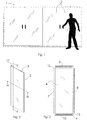
figure 1 is a front view of an industrial fridge whose doors are transparent panels according to the present invention; -
figure 2 is a perspective view of a transparent panel according to the present invention; -
figure 3 is an exploded front view of the panel shown infigure 2 ; -
figure 4 is a sectional view taken along the horizontal plane H-H offigure 2 ; -
figure 5 is a sectional view taken along the vertical plane V-V offigure 2 . -
Figure 1 frontally and schematically shows a refrigerator 1 of the type used in supermarkets for selling fresh, frozen or deep-frozen foods. - In the example shown, the refrigerator 1 is provided with four
transparent doors 2 hinged openable by holding an appropriate handle. -
Figure 2 shows asingle panel 2. In conventional solutions, the frame 3 of the panels used as refrigerator doors is matt, since consisting of a metal frame; in thepanel 2, instead, the frame 3, i.e. the panel perimeter, is at least partly transparent. -
Figures 3-5 allow explaining how this result is obtained.Figure 3 is an exploded front view andfigures 4 and 5 are cross sectional views taken respectively on the horizontal H-H and vertical V-V planes. The views are not to scale, for greater clarity. - With the reference numeral 4 a glass sheet is denoted. Parallel to the
sheet 4 there is asecond glass sheet 5 and between the twosheets 4 and 5 a double glazing 6 is defined, i.e. a chamber in which air is confined or a gas is confined, for example argon, in order to maximize the thermal insulation, i.e. to reduce the transmittance of thedoor 2 and to limit the BTU loss from the refrigerator. - Preferably the
glass sheet 4, the outer one with respect to the refrigerator, is obtained by float process and stands out for a low content of iron oxides. - Preferably the
glass sheet 5 has high level of light transmission (LT equal to at least 70%) and an excellent thermal insulation (Ug = 1.0 W/(m2K)). - If appropriate, the glass sheets are screen-printed or otherwise customized with stickers, for providing the users with indications or simple commercial information.
- Differently from conventional solutions providing the use of metal profiles or glue to keep together the
glass sheets panel 2 according to the present invention provides the use of a plurality of profiles 7-10, some of which 7-8, or all of them, being transparent. - In the example shown in figures, the side profiles 7-8 are made of a transparent material, preferably polycarbonate PC, and are glued to the
glass sheets bottom profiles 9, 10 can be made of metal or a plastic material, for example still in polycarbonate, and in this instance, they can be transparent or not. - In the preferred embodiment, the profiles 7-10 are extruded. This way, seats can be obtained in the profiles 7-10, as it will be explained later, during the extrusion step already.
- Alternatively, the profiles 7-10 can be moulded.
- Preferably, the profiles 7-10 are slightly flexible and not completely stiff as the conventional metal profiles. This feature allows the assembly of the
panel 2 to be facilitated, as it will be clear from the following description. - The
panels 2 can be assembled in the following way. - Firstly, the
glass 4 is placed in a properly made mask (not shown); then a layer C of transparent high-strength adhesive material is cold spread, at the edges of theglass sheet 4, where the coupling with the profiles 7-10 is provided. Then the two top 9 and bottom 10 profiles are positioned (horizontal profiles of the panel 2), and the two left 7 and right 8 side profiles (vertical profiles of the panel 2) are positioned at the edges of thesheet 4 where the adhesive material C has been spread. - As well shown in
figures 4 and 5 , the profiles 7-10 have a substantially T-shaped cross section and this allows obtaining a good shape coupling with theglass sheets sheet 4 is glued to the profiles 7-10, the edges of the sheet complementarily abut against thesides 11 of the profiles, and in such a way that the surfaces of thesheet 4 and the profiles 7-10 remain flush. - Alternatively, as schematically indicated by the dashed
line 12 infigure 4 , the vertical profiles 7 and 8 can also have a rounded cross section. - At this point another adhesive layer C is spread at the profiles 7-10 already coupled to the
sheet 4, and thesecond glass sheet 5 is positioned on the profiles 7-10, care being taken to apply pressure. - The
panel 2 takes thus the shape shown in figures. - At this point, cold UV light lamps are turned on, that cause the adhesive C on the
glass sheets - The adhesive C also has the sealing function for the double glazing 6, meaning that, besides bonding the
glass sheets - An adhesive material suitable for this purpose is commercialized by the Loxeal Company with the code UV3021; it is a methacrylic urethane adhesive.
- Thanks to the fact that also at least the profiles 7-8 are transparent, as well as the
glass sheets panel 2 has greatly pleasant aesthetic. The observer gets the impression that thepanel 2 is free from any frame, in contrast with the impression given by conventional panels made with not-transparent metal profiles. - Substantially the profiles 7-10 do define a frame but this is partially, or completely, also transparent as the glass sheets.
- Referring specifically to
figure 5 , the top 9 and bottom 10 profiles each have aninner seat 13 for housing dehydrating salts, i.e. humidity absorbing salts. Salt presence minimizes the risk of condensation to be produced in the double glazing 6. - One of the advantages of making the
profiles 9, 10 by extrusion is just that theseat 13 can be easily done simultaneously with the extrusion, i.e. theseat 13 can be done without material removal. Therefore, preferably, theseats 13 extend for the whole length of theprofiles 9, 10. - As also shown in
figure 5 , the top 9 and bottom 10 profiles are provided with afurther seat 14 extending parallel to thesalt containing seat 13. - In each seat 14 a
metal bar 15 is inserted with no, or minimum, clearance, having the function of providing an effective anchoring point for the fitting (not shown) intended for supporting thepanel 2 as a door. - In the drawings, the
bars 15 are not to scale. Preferably thebars 15 are battens i.e. they are flat; for example, they have a thickness of about 3 mm. - In
figure 2 with thenumeral reference 17 the holes pierced through the profile 9 for the insertion of screws anchoring to thebar 15 are denoted. In other words, the brackets and the screws used for making the hinges on which thepanel 2 has to rotate, are fixed to thebars 15. Theholes 17 are also present at thebottom profile 10. - In addition to this just described function, the bars have the further function of reinforcing the
panel 2 and reducing the risks it can break due to excessive flexing or twisting of theglass sheets panel 2 up to the stop, the same panel would be less at risk of breakage with respect to what can be easily found now with the solutions conventionally available on the market. Flexing and/or twisting forces produced due to the violent deceleration of thepanel 2 at the stop, when the hinges can not rotate further, are largely absorbed by the metal bars 15 to whom the hinges are connected. - In other words, the
bars 15 inserted in theseats 14 also act as limiters of the wraps thepanel 2 would be subjected to by violently impacting an obstacle or getting quickly to the stop. The Applicant found that the proposed solution greatly reduces the risk of breakage of the fridge doors, with respect to conventional solutions free from bars 15. - Preferably the
bars 15, which can also be defined as "tension bars", are perforated, i.e. have a series of through holes along all the respective extent. In addition to reduce the weight, the holes (not shown) make more flexible thebars 15. - If needed, in the
seats 14 pegs can be inserted, i.e. adapter elements to compensate for or cancel clearances with thebars 15. - If appropriate, the
seats fig. 3 ), for example extruded or moulded plugs. Theplugs 16 can also be angular plugs. - The skilled person in the art will understand that, in general, the
panel 2 can also be made with noseats 13, the latter being preferred but optional. - In the example shown in
figures 1-5 , the number of glass sheets is two. In general, however, thepanel 2 according to the present invention can be made with a larger number of glass sheets, for example three, with double glazing 6. - The skilled person in the art will further understand that the frame 3 could not only be done of transparent profiles 7-10. For example, one of the profiles, the
bottom one 10 and/or the top one 9, could be made of metal or plastic but matt, otherwise they can be coated with an adhesive concealing thebars 15. - If the
panel 2 was made with two chambers 6 and three glass sheets, the profiles 7-10 would have different shape, for example a substantially double-T-shaped cross section, such that a single profile can be used for joining all the three glass sheets, i.e. each profile is shared for constraining all the glass sheets.
Claims (17)
- A double-glazing panel (2) comprising two or more glass sheets (4, 5) and a perimetrical frame (3),
wherein the glass sheets (4, 5) are supported parallel to one another only by the frame (3), and
wherein between the two adjacent glass sheets (4, 5), a chamber (6) containing air or gas is defined, which is sealingly isolated from the outside by the same glass sheets (4, 5) and the frame (3), and
wherein the frame (3) consists of one or more profiles (7-10) glued to the glass sheets (4, 5),
characterized in that at least one of said profiles (7-10) is transparent. - Panel (2) according to claim 1, wherein the glass sheets (4, 5) are rectangular or square and the profiles (7-10) are four, a left vertical profile (7), a right vertical profile (8), a top horizontal profile (9) and a bottom horizontal profile (10), and wherein each of the profiles (7-10) is glued to at least two glass sheets (4, 5), or to all the glass sheets (4, 5), at the respective edges.
- Panel (2) according to claim 1 or claim 2, wherein the profiles (7-10) are made of a plastic material, for example polycarbonate.
- Panel (2) according to any one of claims 1-3, wherein the profiles are extruded or moulded.
- Panel (2) according to any one of preceding claims 1-4, wherein the cross section of the profiles (7-10) are T-shaped and the glass sheets (4, 5) are glued to the profiles (7-10) at the longitudinal portion of the T shape, at opposite sides.
- Panel (2) according to claim 5, wherein the glass sheets (4, 5) are glued to the profiles (7-10) at the longitudinal portion of the T shape, at opposite sides, and are flush with the transversal portion of the T shape.
- Panel (2) according to any one of claims 1-6, wherein the glass sheets (4, 5) and the profiles (7-10) are glued so that to be flush with one another, with no undercuts.
- Panel (2) according to any one of claims 1-7, wherein the glass sheets (4, 5) are glued to the profiles (7-10) by means of a transparent glue acting also as a sealant of the chamber (6).
- Panel (2) according to claim 8, wherein the glue is methacrylic urethane glue.
- Panel (2) according to any one of claims 1-9, wherein at least one of the profiles comprises a first inner seat (13) in which dehydrating salts are housed.
- Panel (2) according to any one of claims 1-10, wherein at least one of the profiles comprises a second inner seat (14), in which a bar (15) is housed and has the double function of:- being an element to which the hinges can be anchored for the use of the panel (2) as door or window;- being a limiting element to limit the deformations the panel (2) is subjected to, in case of violent or quick impacts at the stop.
- Panel (2) according to claim 11, wherein the bars (15) extend for the whole length of the edge of the respective glass sheets (4, 5).
- Panel (2) according to claim 11 or claim 12, wherein the bars (15) are perforated, with through holes or slots, in order to improve the elastic behavior of the bars.
- Panel (2) according to any one of claims 11-13, wherein the bars (15) are flat battens.
- A method for making a double-glazing panel (2) for the use as door or window, comprising:a) extruding or moulding one or more profiles (7-10) made of a transparent plastic material;b) gluing, with transparent glue, at least two glass sheets (4, 5) to the profiles (7-10), at the edges of the glass sheets (4, 5), so that the profiles remain interposed between the parallel glass sheets (4, 5), and between the latter, a chamber (6) containing air or gas is defined;c) causing the solidification of the glue (C) and isolating the chamber (6) between the glass sheets (4, 5) and the profiles (7-10).
- Method according to claim 15, wherein step b) is carried out with methacrylic urethane glue and step c) is carried out by illuminating the glue with cold ultraviolet light.
- A double glazing panel (2) comprising two or more glass sheets (4, 5) and a perimetrical frame (3),
wherein the glass sheets (4, 5) are supported parallel to one another only by the frame (3), and
wherein between the two adjacent glass sheets (4, 5), a chamber (6) containing air or gas is defined, which is sealingly isolated from the outside by the same glass sheets (4, 5) and the frame (3), and
wherein the frame (3) consists of one or more profiles (7-10) glued to the glass sheets (4, 5),
characterized in that
at least one of the profiles comprises an inner seat (14), in which a bar (15) is housed having the double function of:- being an element to which the hinges can be anchored for the use of the panel (2) as door or window;- being a limiting element to limit the warps the panel (2) is subjected to, in case of violent or quick impacts at the stop.
Applications Claiming Priority (1)
| Application Number | Priority Date | Filing Date | Title |
|---|---|---|---|
| IT102017000037854A IT201700037854A1 (en) | 2017-04-06 | 2017-04-06 | TRANSPARENT PANEL |
Publications (2)
| Publication Number | Publication Date |
|---|---|
| EP3385486A1 true EP3385486A1 (en) | 2018-10-10 |
| EP3385486B1 EP3385486B1 (en) | 2023-04-26 |
Family
ID=59325126
Family Applications (1)
| Application Number | Title | Priority Date | Filing Date |
|---|---|---|---|
| EP17179030.6A Active EP3385486B1 (en) | 2017-04-06 | 2017-06-30 | Transparent double glazing panel |
Country Status (3)
| Country | Link |
|---|---|
| EP (1) | EP3385486B1 (en) |
| IT (1) | IT201700037854A1 (en) |
| PT (1) | PT3385486T (en) |
Cited By (4)
| Publication number | Priority date | Publication date | Assignee | Title |
|---|---|---|---|---|
| WO2020130989A3 (en) * | 2018-12-20 | 2020-08-20 | Doğaner Mehmet Fatih | Transparent edge multi-layer glass embodiment |
| IT201900006330A1 (en) * | 2019-04-24 | 2020-10-24 | Tgd Spa | TRANSPARENT GLASS OF THE IMPROVED TYPE |
| WO2020261166A1 (en) * | 2019-06-26 | 2020-12-30 | Hirschler László | Heat-insulating glass panel |
| CN114364857A (en) * | 2019-06-26 | 2022-04-15 | 拉斯洛·赫希勒 | Insulating glass panel |
Citations (10)
| Publication number | Priority date | Publication date | Assignee | Title |
|---|---|---|---|---|
| DE10211940A1 (en) * | 2002-03-18 | 2003-10-02 | Tegralis Gmbh | Door leaf comprises profile frame arranged on holders for the door leaf and glass panes arranged on opposite sides of the profile frame and connected to surfaces of the profile frame which run parallel to the surface of the door leaf |
| WO2010119067A1 (en) * | 2009-04-14 | 2010-10-21 | Gary Paul Beresford | Spacer bar for a multiple panel glazing unit and method of making a spacer bar and a multiple panel glazing unit |
| WO2014198549A1 (en) * | 2013-06-14 | 2014-12-18 | Agc Glass Europe | Glass element for a cabinet having a refrigerated chamber |
| DE202012013218U1 (en) * | 2012-07-10 | 2015-06-25 | Remis Gesellschaft für Entwicklung und Vertrieb von technischen Elementen mbH | fridge |
| US20170016271A1 (en) * | 2014-03-07 | 2017-01-19 | Agc Glass Europe | Insulating glazed element |
| EP2878233B1 (en) | 2013-11-28 | 2017-02-15 | PAN-DUR Holding GmbH & Co. KG | Glass assembly |
| WO2017157636A1 (en) * | 2016-03-18 | 2017-09-21 | Saint Gobain Glass France | Insulating glazing with glass spacer, notably for climate -controlled unit |
| WO2017157637A1 (en) * | 2016-03-18 | 2017-09-21 | Saint Gobain Glass France | Insulating glazing unit, in particular for a climate chamber |
| WO2017157634A1 (en) * | 2016-03-18 | 2017-09-21 | Saint Gobain Glass France | Insulating glazing unit, in particular for a climate chamber |
| WO2017174333A1 (en) * | 2016-04-05 | 2017-10-12 | Saint-Gobain Glass France | Insulating glass unit for a refrigeration unit |
-
2017
- 2017-04-06 IT IT102017000037854A patent/IT201700037854A1/en unknown
- 2017-06-30 EP EP17179030.6A patent/EP3385486B1/en active Active
- 2017-06-30 PT PT171790306T patent/PT3385486T/en unknown
Patent Citations (10)
| Publication number | Priority date | Publication date | Assignee | Title |
|---|---|---|---|---|
| DE10211940A1 (en) * | 2002-03-18 | 2003-10-02 | Tegralis Gmbh | Door leaf comprises profile frame arranged on holders for the door leaf and glass panes arranged on opposite sides of the profile frame and connected to surfaces of the profile frame which run parallel to the surface of the door leaf |
| WO2010119067A1 (en) * | 2009-04-14 | 2010-10-21 | Gary Paul Beresford | Spacer bar for a multiple panel glazing unit and method of making a spacer bar and a multiple panel glazing unit |
| DE202012013218U1 (en) * | 2012-07-10 | 2015-06-25 | Remis Gesellschaft für Entwicklung und Vertrieb von technischen Elementen mbH | fridge |
| WO2014198549A1 (en) * | 2013-06-14 | 2014-12-18 | Agc Glass Europe | Glass element for a cabinet having a refrigerated chamber |
| EP2878233B1 (en) | 2013-11-28 | 2017-02-15 | PAN-DUR Holding GmbH & Co. KG | Glass assembly |
| US20170016271A1 (en) * | 2014-03-07 | 2017-01-19 | Agc Glass Europe | Insulating glazed element |
| WO2017157636A1 (en) * | 2016-03-18 | 2017-09-21 | Saint Gobain Glass France | Insulating glazing with glass spacer, notably for climate -controlled unit |
| WO2017157637A1 (en) * | 2016-03-18 | 2017-09-21 | Saint Gobain Glass France | Insulating glazing unit, in particular for a climate chamber |
| WO2017157634A1 (en) * | 2016-03-18 | 2017-09-21 | Saint Gobain Glass France | Insulating glazing unit, in particular for a climate chamber |
| WO2017174333A1 (en) * | 2016-04-05 | 2017-10-12 | Saint-Gobain Glass France | Insulating glass unit for a refrigeration unit |
Cited By (6)
| Publication number | Priority date | Publication date | Assignee | Title |
|---|---|---|---|---|
| WO2020130989A3 (en) * | 2018-12-20 | 2020-08-20 | Doğaner Mehmet Fatih | Transparent edge multi-layer glass embodiment |
| IT201900006330A1 (en) * | 2019-04-24 | 2020-10-24 | Tgd Spa | TRANSPARENT GLASS OF THE IMPROVED TYPE |
| EP3730731A1 (en) * | 2019-04-24 | 2020-10-28 | TGD S.p.A. | Improved transparent double-glazing unit |
| WO2020261166A1 (en) * | 2019-06-26 | 2020-12-30 | Hirschler László | Heat-insulating glass panel |
| CN114364857A (en) * | 2019-06-26 | 2022-04-15 | 拉斯洛·赫希勒 | Insulating glass panel |
| CN114364857B (en) * | 2019-06-26 | 2023-06-30 | 拉斯洛·赫希勒 | Insulating glass panel |
Also Published As
| Publication number | Publication date |
|---|---|
| EP3385486B1 (en) | 2023-04-26 |
| PT3385486T (en) | 2023-07-26 |
| IT201700037854A1 (en) | 2018-10-06 |
Similar Documents
| Publication | Publication Date | Title |
|---|---|---|
| EP3385486A1 (en) | Transparent panel | |
| CN106061329B (en) | Heat insulating glazing element | |
| US9661940B2 (en) | Glass element for a cabinet having a refrigerated chamber | |
| US9526353B2 (en) | Door for a freezer cabinet | |
| JP2017515082A5 (en) | ||
| US20120324806A1 (en) | High R-Value, Removable and Transparent Window Insulation Panels | |
| JPH07507608A (en) | Doors with foam frames | |
| US20190090660A1 (en) | Insulating glazing unit, in particular for a climate chamber | |
| US5465539A (en) | Window assembly with plant-on | |
| CZ300321B6 (en) | Fire rated door | |
| CN108474235A (en) | Door for refrigerating cabinet | |
| US5675948A (en) | Insulated ventilator for glass block window | |
| NO20120239A1 (en) | Profiled plastic element, especially for windows or window frames. | |
| EP3730731A1 (en) | Improved transparent double-glazing unit | |
| US10760327B2 (en) | Insulating glazing, in particular for a temperature-controlled piece of furniture | |
| KR101472217B1 (en) | A vinyl adiabatic window | |
| UA142703U (en) | WINDOW SYSTEM | |
| BR112021007694A2 (en) | insulated glazing that forms a door or window opening panel, which is frameless in at least part of its periphery | |
| GB2400884A (en) | Glazed window shutters | |
| NZ745141A (en) | Window shutter assembly | |
| ES2328542B1 (en) | DOOR SHEET OF REMOVABLE PANELS FRAMED IN ALUMINUM PROFILE AND WITH INSULATION. | |
| ZA200602659B (en) | Improvements in insulated panels | |
| AU2011202494A1 (en) | Thermally broken frames | |
| GB2407117A (en) | Adhesively mounted, tapered frame section |
Legal Events
| Date | Code | Title | Description |
|---|---|---|---|
| PUAI | Public reference made under article 153(3) epc to a published international application that has entered the european phase |
Free format text: ORIGINAL CODE: 0009012 |
|
| STAA | Information on the status of an ep patent application or granted ep patent |
Free format text: STATUS: THE APPLICATION HAS BEEN PUBLISHED |
|
| AK | Designated contracting states |
Kind code of ref document: A1 Designated state(s): AL AT BE BG CH CY CZ DE DK EE ES FI FR GB GR HR HU IE IS IT LI LT LU LV MC MK MT NL NO PL PT RO RS SE SI SK SM TR |
|
| AX | Request for extension of the european patent |
Extension state: BA ME |
|
| STAA | Information on the status of an ep patent application or granted ep patent |
Free format text: STATUS: REQUEST FOR EXAMINATION WAS MADE |
|
| 17P | Request for examination filed |
Effective date: 20190408 |
|
| RBV | Designated contracting states (corrected) |
Designated state(s): AL AT BE BG CH CY CZ DE DK EE ES FI FR GB GR HR HU IE IS IT LI LT LU LV MC MK MT NL NO PL PT RO RS SE SI SK SM TR |
|
| STAA | Information on the status of an ep patent application or granted ep patent |
Free format text: STATUS: EXAMINATION IS IN PROGRESS |
|
| 17Q | First examination report despatched |
Effective date: 20220302 |
|
| GRAP | Despatch of communication of intention to grant a patent |
Free format text: ORIGINAL CODE: EPIDOSNIGR1 |
|
| STAA | Information on the status of an ep patent application or granted ep patent |
Free format text: STATUS: GRANT OF PATENT IS INTENDED |
|
| INTG | Intention to grant announced |
Effective date: 20221111 |
|
| GRAS | Grant fee paid |
Free format text: ORIGINAL CODE: EPIDOSNIGR3 |
|
| GRAA | (expected) grant |
Free format text: ORIGINAL CODE: 0009210 |
|
| STAA | Information on the status of an ep patent application or granted ep patent |
Free format text: STATUS: THE PATENT HAS BEEN GRANTED |
|
| AK | Designated contracting states |
Kind code of ref document: B1 Designated state(s): AL AT BE BG CH CY CZ DE DK EE ES FI FR GB GR HR HU IE IS IT LI LT LU LV MC MK MT NL NO PL PT RO RS SE SI SK SM TR |
|
| REG | Reference to a national code |
Ref country code: GB Ref legal event code: FG4D |
|
| REG | Reference to a national code |
Ref country code: CH Ref legal event code: EP |
|
| REG | Reference to a national code |
Ref country code: DE Ref legal event code: R096 Ref document number: 602017068016 Country of ref document: DE |
|
| REG | Reference to a national code |
Ref country code: AT Ref legal event code: REF Ref document number: 1562921 Country of ref document: AT Kind code of ref document: T Effective date: 20230515 |
|
| REG | Reference to a national code |
Ref country code: IE Ref legal event code: FG4D |
|
| P01 | Opt-out of the competence of the unified patent court (upc) registered |
Effective date: 20230505 |
|
| REG | Reference to a national code |
Ref country code: PT Ref legal event code: SC4A Ref document number: 3385486 Country of ref document: PT Date of ref document: 20230726 Kind code of ref document: T Free format text: AVAILABILITY OF NATIONAL TRANSLATION Effective date: 20230720 |
|
| REG | Reference to a national code |
Ref country code: SE Ref legal event code: TRGR |
|
| REG | Reference to a national code |
Ref country code: LT Ref legal event code: MG9D |
|
| REG | Reference to a national code |
Ref country code: NL Ref legal event code: MP Effective date: 20230426 |
|
| REG | Reference to a national code |
Ref country code: AT Ref legal event code: MK05 Ref document number: 1562921 Country of ref document: AT Kind code of ref document: T Effective date: 20230426 |
|
| PG25 | Lapsed in a contracting state [announced via postgrant information from national office to epo] |
Ref country code: NL Free format text: LAPSE BECAUSE OF FAILURE TO SUBMIT A TRANSLATION OF THE DESCRIPTION OR TO PAY THE FEE WITHIN THE PRESCRIBED TIME-LIMIT Effective date: 20230426 |
|
| PG25 | Lapsed in a contracting state [announced via postgrant information from national office to epo] |
Ref country code: NO Free format text: LAPSE BECAUSE OF FAILURE TO SUBMIT A TRANSLATION OF THE DESCRIPTION OR TO PAY THE FEE WITHIN THE PRESCRIBED TIME-LIMIT Effective date: 20230726 Ref country code: ES Free format text: LAPSE BECAUSE OF FAILURE TO SUBMIT A TRANSLATION OF THE DESCRIPTION OR TO PAY THE FEE WITHIN THE PRESCRIBED TIME-LIMIT Effective date: 20230426 Ref country code: AT Free format text: LAPSE BECAUSE OF FAILURE TO SUBMIT A TRANSLATION OF THE DESCRIPTION OR TO PAY THE FEE WITHIN THE PRESCRIBED TIME-LIMIT Effective date: 20230426 |
|
| PGFP | Annual fee paid to national office [announced via postgrant information from national office to epo] |
Ref country code: TR Payment date: 20230724 Year of fee payment: 7 Ref country code: RO Payment date: 20230725 Year of fee payment: 7 Ref country code: IT Payment date: 20230712 Year of fee payment: 7 |
|
| PG25 | Lapsed in a contracting state [announced via postgrant information from national office to epo] |
Ref country code: RS Free format text: LAPSE BECAUSE OF FAILURE TO SUBMIT A TRANSLATION OF THE DESCRIPTION OR TO PAY THE FEE WITHIN THE PRESCRIBED TIME-LIMIT Effective date: 20230426 Ref country code: PL Free format text: LAPSE BECAUSE OF FAILURE TO SUBMIT A TRANSLATION OF THE DESCRIPTION OR TO PAY THE FEE WITHIN THE PRESCRIBED TIME-LIMIT Effective date: 20230426 Ref country code: LV Free format text: LAPSE BECAUSE OF FAILURE TO SUBMIT A TRANSLATION OF THE DESCRIPTION OR TO PAY THE FEE WITHIN THE PRESCRIBED TIME-LIMIT Effective date: 20230426 Ref country code: LT Free format text: LAPSE BECAUSE OF FAILURE TO SUBMIT A TRANSLATION OF THE DESCRIPTION OR TO PAY THE FEE WITHIN THE PRESCRIBED TIME-LIMIT Effective date: 20230426 Ref country code: IS Free format text: LAPSE BECAUSE OF FAILURE TO SUBMIT A TRANSLATION OF THE DESCRIPTION OR TO PAY THE FEE WITHIN THE PRESCRIBED TIME-LIMIT Effective date: 20230826 Ref country code: HR Free format text: LAPSE BECAUSE OF FAILURE TO SUBMIT A TRANSLATION OF THE DESCRIPTION OR TO PAY THE FEE WITHIN THE PRESCRIBED TIME-LIMIT Effective date: 20230426 Ref country code: GR Free format text: LAPSE BECAUSE OF FAILURE TO SUBMIT A TRANSLATION OF THE DESCRIPTION OR TO PAY THE FEE WITHIN THE PRESCRIBED TIME-LIMIT Effective date: 20230727 |
|
| PGFP | Annual fee paid to national office [announced via postgrant information from national office to epo] |
Ref country code: SE Payment date: 20230720 Year of fee payment: 7 Ref country code: PT Payment date: 20230727 Year of fee payment: 7 Ref country code: FR Payment date: 20230713 Year of fee payment: 7 Ref country code: DE Payment date: 20230711 Year of fee payment: 7 |
|
| PG25 | Lapsed in a contracting state [announced via postgrant information from national office to epo] |
Ref country code: FI Free format text: LAPSE BECAUSE OF FAILURE TO SUBMIT A TRANSLATION OF THE DESCRIPTION OR TO PAY THE FEE WITHIN THE PRESCRIBED TIME-LIMIT Effective date: 20230426 |
|
| PG25 | Lapsed in a contracting state [announced via postgrant information from national office to epo] |
Ref country code: SK Free format text: LAPSE BECAUSE OF FAILURE TO SUBMIT A TRANSLATION OF THE DESCRIPTION OR TO PAY THE FEE WITHIN THE PRESCRIBED TIME-LIMIT Effective date: 20230426 |
|
| PG25 | Lapsed in a contracting state [announced via postgrant information from national office to epo] |
Ref country code: MC Free format text: LAPSE BECAUSE OF FAILURE TO SUBMIT A TRANSLATION OF THE DESCRIPTION OR TO PAY THE FEE WITHIN THE PRESCRIBED TIME-LIMIT Effective date: 20230426 |
|
| REG | Reference to a national code |
Ref country code: DE Ref legal event code: R097 Ref document number: 602017068016 Country of ref document: DE |
|
| PG25 | Lapsed in a contracting state [announced via postgrant information from national office to epo] |
Ref country code: SM Free format text: LAPSE BECAUSE OF FAILURE TO SUBMIT A TRANSLATION OF THE DESCRIPTION OR TO PAY THE FEE WITHIN THE PRESCRIBED TIME-LIMIT Effective date: 20230426 Ref country code: SK Free format text: LAPSE BECAUSE OF FAILURE TO SUBMIT A TRANSLATION OF THE DESCRIPTION OR TO PAY THE FEE WITHIN THE PRESCRIBED TIME-LIMIT Effective date: 20230426 Ref country code: MC Free format text: LAPSE BECAUSE OF FAILURE TO SUBMIT A TRANSLATION OF THE DESCRIPTION OR TO PAY THE FEE WITHIN THE PRESCRIBED TIME-LIMIT Effective date: 20230426 Ref country code: EE Free format text: LAPSE BECAUSE OF FAILURE TO SUBMIT A TRANSLATION OF THE DESCRIPTION OR TO PAY THE FEE WITHIN THE PRESCRIBED TIME-LIMIT Effective date: 20230426 Ref country code: DK Free format text: LAPSE BECAUSE OF FAILURE TO SUBMIT A TRANSLATION OF THE DESCRIPTION OR TO PAY THE FEE WITHIN THE PRESCRIBED TIME-LIMIT Effective date: 20230426 Ref country code: CZ Free format text: LAPSE BECAUSE OF FAILURE TO SUBMIT A TRANSLATION OF THE DESCRIPTION OR TO PAY THE FEE WITHIN THE PRESCRIBED TIME-LIMIT Effective date: 20230426 |
|
| REG | Reference to a national code |
Ref country code: CH Ref legal event code: PL |
|
| REG | Reference to a national code |
Ref country code: BE Ref legal event code: MM Effective date: 20230630 |
|
| PG25 | Lapsed in a contracting state [announced via postgrant information from national office to epo] |
Ref country code: LU Free format text: LAPSE BECAUSE OF NON-PAYMENT OF DUE FEES Effective date: 20230630 |
|
| PLBE | No opposition filed within time limit |
Free format text: ORIGINAL CODE: 0009261 |
|
| STAA | Information on the status of an ep patent application or granted ep patent |
Free format text: STATUS: NO OPPOSITION FILED WITHIN TIME LIMIT |
|
| GBPC | Gb: european patent ceased through non-payment of renewal fee |
Effective date: 20230726 |
|
| REG | Reference to a national code |
Ref country code: IE Ref legal event code: MM4A |
|
| PG25 | Lapsed in a contracting state [announced via postgrant information from national office to epo] |
Ref country code: LU Free format text: LAPSE BECAUSE OF NON-PAYMENT OF DUE FEES Effective date: 20230630 |
|
| 26N | No opposition filed |
Effective date: 20240129 |
|
| PG25 | Lapsed in a contracting state [announced via postgrant information from national office to epo] |
Ref country code: IE Free format text: LAPSE BECAUSE OF NON-PAYMENT OF DUE FEES Effective date: 20230630 |