EP3384624B1 - Method and apparatus for decoupling uplink latency using common uplink burst in tdd subframe structure - Google Patents
Method and apparatus for decoupling uplink latency using common uplink burst in tdd subframe structure Download PDFInfo
- Publication number
- EP3384624B1 EP3384624B1 EP16806341.0A EP16806341A EP3384624B1 EP 3384624 B1 EP3384624 B1 EP 3384624B1 EP 16806341 A EP16806341 A EP 16806341A EP 3384624 B1 EP3384624 B1 EP 3384624B1
- Authority
- EP
- European Patent Office
- Prior art keywords
- frame
- burst
- common
- centric sub
- sub
- Prior art date
- Legal status (The legal status is an assumption and is not a legal conclusion. Google has not performed a legal analysis and makes no representation as to the accuracy of the status listed.)
- Active
Links
Images


Classifications
-
- H—ELECTRICITY
- H04—ELECTRIC COMMUNICATION TECHNIQUE
- H04W—WIRELESS COMMUNICATION NETWORKS
- H04W72/00—Local resource management
- H04W72/12—Wireless traffic scheduling
- H04W72/1263—Mapping of traffic onto schedule, e.g. scheduled allocation or multiplexing of flows
- H04W72/1268—Mapping of traffic onto schedule, e.g. scheduled allocation or multiplexing of flows of uplink data flows
-
- H—ELECTRICITY
- H04—ELECTRIC COMMUNICATION TECHNIQUE
- H04L—TRANSMISSION OF DIGITAL INFORMATION, e.g. TELEGRAPHIC COMMUNICATION
- H04L1/00—Arrangements for detecting or preventing errors in the information received
- H04L1/0001—Systems modifying transmission characteristics according to link quality, e.g. power backoff
- H04L1/0015—Systems modifying transmission characteristics according to link quality, e.g. power backoff characterised by the adaptation strategy
- H04L1/0017—Systems modifying transmission characteristics according to link quality, e.g. power backoff characterised by the adaptation strategy where the mode-switching is based on Quality of Service requirement
- H04L1/0018—Systems modifying transmission characteristics according to link quality, e.g. power backoff characterised by the adaptation strategy where the mode-switching is based on Quality of Service requirement based on latency requirement
-
- H—ELECTRICITY
- H04—ELECTRIC COMMUNICATION TECHNIQUE
- H04L—TRANSMISSION OF DIGITAL INFORMATION, e.g. TELEGRAPHIC COMMUNICATION
- H04L5/00—Arrangements affording multiple use of the transmission path
- H04L5/0001—Arrangements for dividing the transmission path
- H04L5/0003—Two-dimensional division
- H04L5/0005—Time-frequency
- H04L5/0007—Time-frequency the frequencies being orthogonal, e.g. OFDM(A) or DMT
-
- H—ELECTRICITY
- H04—ELECTRIC COMMUNICATION TECHNIQUE
- H04L—TRANSMISSION OF DIGITAL INFORMATION, e.g. TELEGRAPHIC COMMUNICATION
- H04L5/00—Arrangements affording multiple use of the transmission path
- H04L5/003—Arrangements for allocating sub-channels of the transmission path
- H04L5/0044—Allocation of payload; Allocation of data channels, e.g. PDSCH or PUSCH
-
- H—ELECTRICITY
- H04—ELECTRIC COMMUNICATION TECHNIQUE
- H04L—TRANSMISSION OF DIGITAL INFORMATION, e.g. TELEGRAPHIC COMMUNICATION
- H04L5/00—Arrangements affording multiple use of the transmission path
- H04L5/003—Arrangements for allocating sub-channels of the transmission path
- H04L5/0048—Allocation of pilot signals, i.e. of signals known to the receiver
- H04L5/005—Allocation of pilot signals, i.e. of signals known to the receiver of common pilots, i.e. pilots destined for multiple users or terminals
-
- H—ELECTRICITY
- H04—ELECTRIC COMMUNICATION TECHNIQUE
- H04L—TRANSMISSION OF DIGITAL INFORMATION, e.g. TELEGRAPHIC COMMUNICATION
- H04L5/00—Arrangements affording multiple use of the transmission path
- H04L5/003—Arrangements for allocating sub-channels of the transmission path
- H04L5/0048—Allocation of pilot signals, i.e. of signals known to the receiver
- H04L5/0051—Allocation of pilot signals, i.e. of signals known to the receiver of dedicated pilots, i.e. pilots destined for a single user or terminal
-
- H—ELECTRICITY
- H04—ELECTRIC COMMUNICATION TECHNIQUE
- H04L—TRANSMISSION OF DIGITAL INFORMATION, e.g. TELEGRAPHIC COMMUNICATION
- H04L5/00—Arrangements affording multiple use of the transmission path
- H04L5/003—Arrangements for allocating sub-channels of the transmission path
- H04L5/0053—Allocation of signalling, i.e. of overhead other than pilot signals
- H04L5/0055—Physical resource allocation for ACK/NACK
-
- H—ELECTRICITY
- H04—ELECTRIC COMMUNICATION TECHNIQUE
- H04L—TRANSMISSION OF DIGITAL INFORMATION, e.g. TELEGRAPHIC COMMUNICATION
- H04L5/00—Arrangements affording multiple use of the transmission path
- H04L5/14—Two-way operation using the same type of signal, i.e. duplex
-
- H—ELECTRICITY
- H04—ELECTRIC COMMUNICATION TECHNIQUE
- H04L—TRANSMISSION OF DIGITAL INFORMATION, e.g. TELEGRAPHIC COMMUNICATION
- H04L5/00—Arrangements affording multiple use of the transmission path
- H04L5/14—Two-way operation using the same type of signal, i.e. duplex
- H04L5/1469—Two-way operation using the same type of signal, i.e. duplex using time-sharing
-
- H—ELECTRICITY
- H04—ELECTRIC COMMUNICATION TECHNIQUE
- H04L—TRANSMISSION OF DIGITAL INFORMATION, e.g. TELEGRAPHIC COMMUNICATION
- H04L69/00—Network arrangements, protocols or services independent of the application payload and not provided for in the other groups of this subclass
- H04L69/22—Parsing or analysis of headers
-
- H—ELECTRICITY
- H04—ELECTRIC COMMUNICATION TECHNIQUE
- H04L—TRANSMISSION OF DIGITAL INFORMATION, e.g. TELEGRAPHIC COMMUNICATION
- H04L69/00—Network arrangements, protocols or services independent of the application payload and not provided for in the other groups of this subclass
- H04L69/30—Definitions, standards or architectural aspects of layered protocol stacks
- H04L69/32—Architecture of open systems interconnection [OSI] 7-layer type protocol stacks, e.g. the interfaces between the data link level and the physical level
- H04L69/322—Intralayer communication protocols among peer entities or protocol data unit [PDU] definitions
- H04L69/323—Intralayer communication protocols among peer entities or protocol data unit [PDU] definitions in the physical layer [OSI layer 1]
-
- H—ELECTRICITY
- H04—ELECTRIC COMMUNICATION TECHNIQUE
- H04W—WIRELESS COMMUNICATION NETWORKS
- H04W52/00—Power management, e.g. Transmission Power Control [TPC] or power classes
- H04W52/04—Transmission power control [TPC]
- H04W52/30—Transmission power control [TPC] using constraints in the total amount of available transmission power
- H04W52/36—Transmission power control [TPC] using constraints in the total amount of available transmission power with a discrete range or set of values, e.g. step size, ramping or offsets
- H04W52/365—Power headroom reporting
-
- H—ELECTRICITY
- H04—ELECTRIC COMMUNICATION TECHNIQUE
- H04W—WIRELESS COMMUNICATION NETWORKS
- H04W72/00—Local resource management
- H04W72/04—Wireless resource allocation
- H04W72/044—Wireless resource allocation based on the type of the allocated resource
- H04W72/0446—Resources in time domain, e.g. slots or frames
-
- H—ELECTRICITY
- H04—ELECTRIC COMMUNICATION TECHNIQUE
- H04W—WIRELESS COMMUNICATION NETWORKS
- H04W72/00—Local resource management
- H04W72/12—Wireless traffic scheduling
- H04W72/1263—Mapping of traffic onto schedule, e.g. scheduled allocation or multiplexing of flows
- H04W72/1273—Mapping of traffic onto schedule, e.g. scheduled allocation or multiplexing of flows of downlink data flows
-
- H—ELECTRICITY
- H04—ELECTRIC COMMUNICATION TECHNIQUE
- H04W—WIRELESS COMMUNICATION NETWORKS
- H04W72/00—Local resource management
- H04W72/20—Control channels or signalling for resource management
- H04W72/21—Control channels or signalling for resource management in the uplink direction of a wireless link, i.e. towards the network
-
- H—ELECTRICITY
- H04—ELECTRIC COMMUNICATION TECHNIQUE
- H04W—WIRELESS COMMUNICATION NETWORKS
- H04W88/00—Devices specially adapted for wireless communication networks, e.g. terminals, base stations or access point devices
- H04W88/02—Terminal devices
-
- H—ELECTRICITY
- H04—ELECTRIC COMMUNICATION TECHNIQUE
- H04W—WIRELESS COMMUNICATION NETWORKS
- H04W88/00—Devices specially adapted for wireless communication networks, e.g. terminals, base stations or access point devices
- H04W88/08—Access point devices
Definitions
- This application relates to wireless communication systems, and more particularly to decoupling uplink latency using common uplink bursts in Time Division Duplex (TDD) sub-frame structures.
- TDD Time Division Duplex
- 5G networks which requires a broader frequency spectrum.
- a plethora of unpaired spectrum is available at a high frequency band, which is also less expensive than the paired spectrum at frequencies of 2 GHz and below.
- Wireless communications on the unpaired spectrum is typically performed in Time Division Duplex (TDD) mode, where uplink transmission (e.g., transmission from user equipment (UE) to evolved Node B (eNB)) and downlink transmission (e.g., transmission from eNB to UE) share the same frequency spectrum, but are separated in time.
- TDD Time Division Duplex
- AL. Radio interface evolution towards 5G and enhanced local area communications
- IEEE ACCESS, vol. 2, pages 1005-1029 relates to models for enhancement of wireless communications, particularly 5G. Toni Levanen ET.
- AL. "New Spectrally and Energy Efficient Flexible TDD Based Air Interface for 5G Small Ceils", 2014 IEEE 79th Vehicular Technology Conference, 1 May 2014, pages 1-7 , relates to models for enhancement of wireless communications, particularly 5G. LEVANEN TONI ET.
- a method for wireless communications includes transmitting, from a user equipment (UE) to a base station (BS), a common uplink (UL) burst in each sub-frame communicated between the UE and the BS, wherein the common UL burst comprises at least one of a physical layer (PHY) acknowledgement (ACK), a scheduling request, a buffer status report (BSR), or a sounding reference signal (SRS), and transmitting, from the UE, scheduled UL payload data in at least one common UL burst of at least one sub-frame communicated between the UE and the BS.
- PHY physical layer
- BSR buffer status report
- SRS sounding reference signal
- an apparatus includes a transmitter configured to transmit, to another apparatus, a common uplink (UL) burst in each sub-frame communicated between the apparatus and the other apparatus, wherein the common UL burst comprises at least one of a physical layer (PHY) acknowledgement (ACK), a scheduling request (SR), a buffer status report (BSR), or a sounding reference signal (SRS), and a transmitter is further configured to transmit scheduled UL payload data in at least one common UL burst of at least one sub-frame communicated between the apparatus and the other apparatus.
- PHY physical layer
- SR scheduling request
- BSR buffer status report
- SRS sounding reference signal
- an apparatus includes means for transmitting, to another apparatus, a common uplink (UL) burst in each sub-frame communicated between the apparatus and the other apparatus, wherein the common UL burst comprises at least one of a physical layer (PHY) acknowledgement (ACK), a scheduling request (SR), a buffer status report (BSR), or a sounding reference signal (SRS), and wherein the means for transmitting is further configured to transmit scheduled UL payload data in at least one common UL burst of at least one sub-frame communicated between the apparatus and the other apparatus.
- PHY physical layer
- SR scheduling request
- BSR buffer status report
- SRS sounding reference signal
- a computer-readable medium having program code recorded thereon includes program code comprising code for causing a user equipment (UE) to transmit, to a base station (BS), a common uplink (UL) burst in each sub-frame communicated between the UE and the BS, wherein the common UL burst comprises at least one of a physical layer (PHY) acknowledgement (ACK), a scheduling request (SR), a buffer status report (BSR), or a sounding reference signal (SRS), and code for causing the UE to transmit scheduled UL payload data in at least one common UL burst of at least one sub-frame communicated between the UE and the BS.
- PHY physical layer
- SR scheduling request
- BSR buffer status report
- SRS sounding reference signal
- a method for wireless communications includes receiving, at a base station (BS) from a user equipment (UE), a common uplink (UL) burst in each sub-frame communicated between the UE and the BS, wherein the common UL burst comprises at least one of a physical layer (PHY) acknowledgement (ACK), a scheduling request (SR), a buffer status report (BSR), or a sounding reference signal (SRS), and receiving, at the BS, an UL payload data within at least one common UL burst of at least one sub-frame communicated between the UE and the BS.
- PHY physical layer
- SR scheduling request
- BSR buffer status report
- SRS sounding reference signal
- an apparatus includes a receiver configured to receive, from another apparatus, a common uplink (UL) burst in each sub-frame communicated between the other apparatus and the apparatus, wherein the common UL burst comprises at least one of a physical layer (PHY) acknowledgement (ACK), a scheduling request (SR), a buffer status report (BSR), or a sounding reference signal (SRS), and wherein the receiver is further configured to receive an UL payload data within at least one common UL burst of at least one sub-frame communicated between the other apparatus and the apparatus.
- PHY physical layer
- SR scheduling request
- BSR buffer status report
- SRS sounding reference signal
- an apparatus includes means for receiving, from another apparatus, a common uplink (UL) burst in each sub-frame communicated between the other apparatus and the apparatus, wherein the common UL burst comprises at least one of a physical layer (PHY) acknowledgement (ACK), a scheduling request (SR), a buffer status report (BSR), or a sounding reference signal (SRS), and wherein the means for receiving is further configured to receive an UL payload data within at least one common UL burst of at least one sub-frame communicated between the other apparatus and the apparatus
- PHY physical layer
- SR scheduling request
- BSR buffer status report
- SRS sounding reference signal
- a computer-readable medium having program code recorded thereon includes program code comprising code for causing a base station (BS) to receive, from a user equipment (UE), a common uplink (UL) burst in each sub-frame communicated between the UE and the BS, wherein the common UL burst comprises at least one of a physical layer (PHY) acknowledgement (ACK), a scheduling request (SR), a buffer status report (BSR), or a sounding reference signal (SRS), and code for causing the BS to receive an UL payload data within at least one common UL burst of at least one sub-frame communicated between the UE and the BS.
- PHY physical layer
- SR scheduling request
- BSR buffer status report
- SRS sounding reference signal
- a CDMA network may implement a radio technology such as Universal Terrestrial Radio Access (UTRA), cdma2000, etc.
- UTRA includes Wideband CDMA (WCDMA) and other variants of CDMA.
- cdma2000 covers IS-2000, IS-95 and IS-856 standards.
- a TDMA network may implement a radio technology such as Global System for Mobile Communications (GSM).
- GSM Global System for Mobile Communications
- An OFDMA network may implement a radio technology such as Evolved UTRA (E-UTRA), Ultra Mobile Broadband (UMB), IEEE 802.11 (Wi-Fi), IEEE 802.16 (WiMAX), IEEE 802.20, Flash-OFDMA, etc.
- E-UTRA Evolved UTRA
- UMB Ultra Mobile Broadband
- IEEE 802.11 Wi-Fi
- WiMAX IEEE 802.16
- Flash-OFDMA Flash-OFDMA
- UTRA and E-UTRA are part of Universal Mobile Telecommunication System (UMTS).
- 3GPP Long Term Evolution (LTE) and LTE-Advanced (LTE-A) are new (e.g., 4G networks) releases of UMTS that use E-UTRA.
- UTRA, E-UTRA, UMTS, LTE, LTE-A and GSM are described in documents from an organization named "3rd Generation Partnership Project" (3GPP).
- CDMA2000 and UMB are described in documents from an organization named "3rd Generation Partnership Project 2" (3GPP2).
- 3GPP2 3rd Generation Partnership Project 2
- the techniques described herein may be used for the wireless networks and radio technologies mentioned above as well as other wireless networks and radio technologies, such as a next generation (e.g., 5 th Generation (5G)) network.
- 5G 5 th Generation
- FIG. 1 illustrates a wireless communication network 100 in accordance with various aspects of the present disclosure.
- the wireless network 100 may include a number of base stations 104 and a number of user equipment (UE) 106, all within one or more cells 102 as illustrated in FIG. 1 .
- FIG. 1 shows base stations 104a, 104b, and 104c associated with cells 102a, 102b, and 102c, respectively.
- the communications environment 100 may support operation on multiple carriers (e.g., waveform signals of different frequencies).
- Multi-carrier transmitters can transmit modulated signals simultaneously on the multiple carriers.
- each modulated signal may be a multi-carrier channel modulated according to the various radio technologies described above.
- Each modulated signal may be sent on a different carrier and may carry control information (e.g., pilot signals, control channels, etc.), overhead information, data, etc.
- the communications environment 100 may be a multi-carrier LTE network capable of efficiently allocating network resources.
- the communications environment 100 is one example of a network to which various aspects of the disclosure apply.
- a base station (BS) 104 as discussed herein can have various characteristics. In some scenarios, it may include an evolved Node B (eNodeB or eNB) in the LTE context, for example.
- eNodeB evolved Node B
- a base station 104 may also be referred to as a base transceiver station or an access point. It will be recognized that there could be one to many base stations, as well as be an assortment of different types such as macro, pico, and/or femto base stations.
- the base stations 104 may communicate with each other and other network elements via one or more backhaul links.
- the base stations 104 communicate with the UEs 106 as shown, including via direct wireless connections or indirect, e.g., via relay devices.
- a UE 106 may communicate with a base station 104 via an uplink and a downlink.
- the downlink (or forward link) refers to the communication link from a base station 104 to a UE 106.
- the uplink (or reverse link) refers to the communication link from a UE 106 to a base station 104.
- the UEs 106 may be dispersed throughout the wireless network 100, and each UE 106 may be stationary or mobile.
- a UE may also be referred to as a terminal, a mobile station, a subscriber unit, etc.
- a UE 106 may be a cellular phone, a smartphone, a personal digital assistant, a wireless modem, a laptop computer, a tablet computer, entertainment device, medical device/equipment, biometric devices/equipment, fitness/exercise devices, vehicular components/sensors, etc.
- the wireless communication network 100 is one example of a network to which various aspects of the disclosure apply.
- FIG. 2 is a block diagram of UE 106 according to embodiments of the present disclosure.
- the UE 106 may include a processor 202, a memory 204, a transmission access resource selection module 208, a transceiver 210, and an antenna 216. These elements may be in direct or indirect communication with each other, for example via one or more buses.
- the processor 202 may include a central processing unit (CPU), a digital signal processor (DSP), an application-specific integrated circuit (ASIC), a controller, a field programmable gate array (FPGA) device, another hardware device, a firmware device, or any combination thereof configured to perform the operations described herein.
- the processor 202 may also be implemented as a combination of computing devices, e.g., a combination of a DSP and a microprocessor, a plurality of microprocessors, one or more microprocessors in conjunction with a DSP core, or any other such configuration.
- the memory 204 may include a cache memory (e.g., a cache memory of the processor 442), random access memory (RAM), magnetoresistive RAM (MRAM), read-only memory (ROM), programmable read-only memory (PROM), erasable programmable read only memory (EPROM), electrically erasable programmable read only memory (EEPROM), flash memory, solid state memory device, hard disk drives, other forms of volatile and non-volatile memory, or a combination of different types of memory.
- the memory 204 includes a non-transitory computer-readable medium.
- the memory 204 may store instructions 206.
- the instructions 206 may include instructions that, when executed by the processor 202, cause the processor 202 to perform the operations described herein with reference to the UE 106 in connection with embodiments of the present disclosure. Instructions 206 may also be referred to as code.
- the terms "instructions” and “code” may include any type of computer-readable statement(s). For example, the terms “instructions” and “code” may refer to one or more programs, routines, sub-routines, functions, procedures, etc. "Instructions" and “code” may include a single computer-readable statement or many computer-readable statements.
- the transmission access resource selection module 208 may be configured to select and assign resources (e.g., time resources and/or frequency resources) for transmission of uplink bursts from UE 106, discussed in more detail below.
- the transceiver 210 may include a modem subsystem 212 and a radio frequency (RF) unit 214.
- the transceiver 210 is configured to communicate bi-directionally with other devices, such as base stations 104.
- the modem subsystem 212 may be configured to modulate and/or encode the data from the memory 204 and/or the transmission access resource selection module 208 (and/or from another source, such as some type of sensor) according to a modulation and coding scheme (MCS), e.g., a low-density parity check (LDPC) coding scheme, a turbo coding scheme, a convolutional coding scheme, etc.
- MCS modulation and coding scheme
- LDPC low-density parity check
- the RF unit 214 may be configured to process (e.g., perform analog to digital conversion or digital to analog conversion, etc.) modulated/encoded data from the modem subsystem 212 (on outbound transmissions) or of transmissions originating from another source such as a base station 104. Although shown as integrated together in transceiver 210, the modem subsystem 212 and the RF unit 214 may be separate devices that are coupled together at the UE 106 to enable the UE 106 to communicate with other devices.
- process e.g., perform analog to digital conversion or digital to analog conversion, etc.
- the RF unit 214 may provide the modulated and/or processed data, e.g. data packets (or, more generally, data messages which may contain one or more data packets and other information), to the antenna 216 for transmission to one or more other devices. This may include, for example, transmission of data to a base station 104 according to embodiments of the present disclosure.
- the antenna 216 may further receive data messages transmitted from a base station 104 and provide the received data messages for processing and/or demodulation at the transceiver 210.
- FIG. 2 illustrates antenna 216 as a single antenna, antenna 216 may include multiple antennas of similar or different designs in order to sustain multiple transmission links.
- FIG. 3 is a block diagram of an exemplary base station 104 according to embodiments of the present disclosure.
- the base station 104 may include a processor 302, a memory 304, a resource coordination module 308, a transceiver 310, and an antenna 316. These elements may be in direct or indirect communication with each other, for example via one or more buses.
- the base station 104 may be an evolved Node B (eNodeB or eNB), a macro cell, a pico cell, a femto cell, a relay station, an access point, or another electronic device operable to perform the operations described herein with respect to the base station 104.
- eNodeB or eNB evolved Node B
- a macro cell a pico cell, a femto cell, a relay station, an access point, or another electronic device operable to perform the operations described herein with respect to the base station 104.
- the base station 104 may operate in accordance with one or more communication standards, such as a 3rd generation (3G) wireless communication standard, a 4th generation (4G) wireless communication standard, a long term evolution (LTE) wireless communication standard, an LTE-advanced wireless communication standard, or another wireless communication standard now known or later developed (e.g., a next generation network operating according to a 5G protocol).
- 3G 3rd generation
- 4G 4th generation
- LTE long term evolution
- LTE-advanced wireless communication standard an LTE-advanced wireless communication standard
- another wireless communication standard now known or later developed (e.g., a next generation network operating according to a 5G protocol).
- the processor 302 may include a CPU, a DSP, an ASIC, a controller, a FPGA device, another hardware device, a firmware device, or any combination thereof configured to perform the operations described herein with reference to the base station 104 introduced in FIG. 1 above.
- the processor 302 may also be implemented as a combination of computing devices, e.g., a combination of a DSP and a microprocessor, a plurality of microprocessors, one or more microprocessors in conjunction with a DSP core, or any other such configuration.
- the memory 304 may include a cache memory (e.g., a cache memory of the processor 302), RAM, MRAM, ROM, PROM, EPROM, EEPROM, flash memory, a solid state memory device, one or more hard disk drives, other forms of volatile and non-volatile memory, or a combination of different types of memory.
- the memory 304 includes a non-transitory computer-readable medium.
- the memory 304 may store instructions 306.
- the instructions 306 may include instructions that, when executed by the processor 302, cause the processor 302 to perform the operations described herein with reference to the base station 104 in connection with embodiments of the present disclosure.
- Instructions 306 may also be referred to as code, which may be interpreted broadly to include any type of computer-readable statement(s) as discussed above with respect to FIG. 2 .
- the resource coordination module 308 may be configured to coordinate resource usage (e.g., time resources and/or frequency resources) among the base stations 104 when communicating with the UEs 106, such as to mitigate or at least reduce interference among the base stations 104.
- the transceiver 310 may include a modem subsystem 312 and a radio frequency (RF) unit 314.
- the transceiver 310 is configured to communicate bi-directionally with other devices, such as UEs 106.
- the modem subsystem 312 may be configured to modulate and/or encode data according to a MCS, some examples of which have been listed above with respect to FIG. 2 .
- the RF unit 314 may be configured to process (e.g., perform analog to digital conversion or digital to analog conversion, etc.) of modulated/encoded data from the modem subsystem 312 (on outbound transmissions) or of transmissions originating from another source, such as an UE 106.
- the modem subsystem 312 and the RF unit 314 may be separate devices that are coupled together at the base station 104 to enable the base station 104 to communicate with other devices.
- the RF unit 314 may provide the modulated and/or processed data, e.g. data packets, to the antenna 316 for transmission to one or more other devices such as UEs 106.
- the modem subsystem 312 may modulate and/or encode the data in preparation for transmission.
- the RF unit 314 may receive the modulated and/or encoded data packet and process the data packet prior to passing it on to the antenna 316. This may include, for example, transmission of data messages to UEs 106 or to another base station 104, according to embodiments of the present disclosure.
- the antenna 316 may further receive data messages transmitted from UEs 106, and provide the received data messages for processing and/or demodulation at the transceiver 310.
- FIG. 3 illustrates antenna 316 as a single antenna, antenna 316 may include multiple antennas of similar or different designs in order to sustain multiple transmission links.
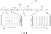
- FIG. 4 is a self-contained Time Division Duplex (TDD) sub-frame structure 400 with a common uplink burst design according to embodiments of the present disclosure.
- the TDD sub-frame structure 400 may comprise a plurality of downlink (DL) centric sub-frames 402 and at least one uplink (UL) centric sub-frame 404 for each communication cycle 406 between eNB (e.g., eNB 104) and UE (e.g., UE 106).
- Each DL centric sub-frame 402 may comprise a Physical Downlink Shared Channel (PDSCH) 408 (long DL burst), and a common UL burst 410 (short UL burst).
- PDSCH Physical Downlink Shared Channel
- Each UL centric sub-frame 404 may comprise a short DL burst 412 and a long UL burst 414.
- a number of DL centric sub-frames 402 per communication cycle 406 can be greater than a number of UL centric sub-frames 404.
- the ratio can be fixed or variable. In some instances, the number of UL centric sub-frames 404 is greater than the number of DL centric sub-frames 402.
- each DL centric sub-frame 402 and UL centric sub-frame 404 of the TDD sub-frame structure 400 may be communicated during a transmission time interval (TTI) with duration of 0.25 ms (e.g., short sub-frame structure).
- TTI transmission time interval
- each common UL burst structure e.g., the common UL burst 412, and the common UL burst 4108 may comprise, for example, two short orthogonal frequency division multiplexing (OFDM) symbols having duration of approximately 33 ⁇ s (e.g., for sub-carrier spacing of 60 kHz).
- OFDM orthogonal frequency division multiplexing
- Embodiments of the present disclosure relate to decoupling uplink control latency from the UL/DL switching pattern using common UL burst.
- a Physical layer (PHY) Acknowledgement (ACK) or a Negative Acknowledgement (NACK) in DL centric sub-frames 402 may be time critical information.
- the ACK/NACK may be transmitted to acknowledge (or negatively acknowledge) DL data sent on PDSCH.
- the objective may be to transmit ACK/NACK within the same sub-frame as the PDSCH (achieving self-contained) in to reduce Hybrid Automatic Repeat Request (HARQ) delay.
- HARQ Hybrid Automatic Repeat Request
- a Scheduling Request (SR) bit may be time critical information.
- the SR bit may indicate a request for the eNB to provide UL grant so that the UE can transmit Physical Uplink Shared Channel (PUSCH).
- the objective may be to transmit SR from the UE to the eNB in either DL centric sub-frame 402 or in UL centric sub-frame 404 in order to avoid extra latency in waiting for UL centric sub-frame 404.
- SR may also include information about Buffer Status Report (BSR) at the UE.
- BSR may provide a serving eNB with information about an amount of data available for transmission in UL buffers of the UE.
- a Sounding Reference Signal may be time critical information.
- the SRS transmitted from the UE to the eNB may allow the eNB to quickly sound a channel between the eNB and the UE whenever there is a DL traffic.
- the SRS received at the eNB may also allow the eNB to closely track the channel fading.
- the SRS may be received by the eNB immediately before the DL burst is transmitted from the eNB to the UE.
- these time critical information e.g., at least one of ACK, NACK, SR, BSR, or SRS
- FIG. 5 is a diagram 500 illustrating common UL burst across different sub-frame types according to embodiments of the present disclosure.
- each DL centric sub-frame 502 may comprise a Physical Downlink Control Channel (PDCCH) 504, a Physical Downlink Shared Channel (PDSCH) 506, and a common UL burst 508.
- Each UL centric sub-frame 510 may comprise a PDCCH 512, a regular UL burst 514, and a common UL burst 516.
- the same common UL burst structure may be present in both the DL centric sub-frames and the UL centric sub-frames, e.g., the common UL bursts 508 and 516 may comprise the same structure incorporated into each DL centric sub-frame 502 and each UL centric sub-frame 510.
- the common UL burst may be present in all sub-frames.
- DL-centric sub-frames may comprise (beside DL channels) only the common UL burst (e.g., the common UL burst 508), whereas UL-centric sub-frames may comprise both the regular UL burst (e.g., regular UL burst 514 in FIG. 5 ) and the common UL burst (e.g., the common UL burst 516).
- the common UL burst in all sub-frames may occupy the same frequency/time resources within the network.
- time critical UL control information may be transmitted in a common UL burst of either DL centric sub-frame (e.g., in common UL burst 508) or UL centric sub-frame (e.g., in common UL burst 516).
- time critical UL control information may comprise at least one of PHY ACK/NACK, SR, BSR, or SRS.
- a UE can opportunistically send Physical Uplink Shared Channel (PUSCH) data depending on available uplink headroom. This may be applicable to small cell or macro cell center users.
- PUSCH Physical Uplink Shared Channel
- a common UL burst (e.g., in either DL centric sub-frame or UL centric sub-frame) may be used, by a UE, to transmit scheduled uplink payload data (e.g., PUSCH) in order to achieve low latency. Therefore, low latency uplink data may be communicated between the UE and the eNB using the common UL burst.
- Certain applications have requirements on a tolerable delay for uplink data.
- application layer ACK may need to be transmitted within a short time window.
- Users with enough power headroom may utilize a common UL burst to transmit the low latency uplink data. This may be applicable to small cells or cell users in large cells.
- those UEs that want to use common uplink burst to transmit payload data need to transmit an appropriate request to the eNB. Then, the eNB may schedule, based upon the received request, transmission of UL payload data in common UL bursts based on the UE's power headroom and resource availability.
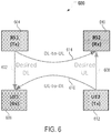
- FIG. 6 is a diagram 600 of an example communication causing mixed interference among different cells according to embodiments of the present disclosure.
- the eNB can potentially change communication of some scheduled DL-centric sub-frames into UL-centric sub-frames (and vice versa) within a cell, depending on traffic needs.
- This dynamic DL-UL switching may cause mixed interference among different cells.
- DL transmission 602 of base station 604 may interfere with UL communication 608 received at base station 610 (e.g., DL-to-UL interference 614 occurring at base station 604 and base station 610 of different cells).
- UL transmission 608 from UE 612 may interfere with DL communication 602 at UE 606 (e.g., UL-to-DL interference 616 occurring at UE 606 and UE 612 of different cells).
- common uplink design may allow the uplink control information to be communicated without causing mixed interference during dynamic UL-DL switching.
- FIG. 7 is a structure 700 illustrating TDD communication among different cells for avoiding mixed interference according to embodiments of the present disclosure.
- UL-to-DL switching may occur (e.g., due to certain traffic needs), and there may be simultaneous communication of UL centric sub-frame 702 in Cell 1 and DL centric sub-frame 704 in Cell 2.
- the UL centric sub-frame 702 may comprise PDCCH 706, regular UL burst 708, and common UL burst 710
- DL centric sub-frame 704 may comprise PDCCH 712, DL burst 714, and common UL burst 716, as illustrated in FIG. 7 .
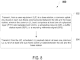
- FIG. 8 is a flowchart illustrating an exemplary method 800 for according to embodiments of the present disclosure.
- the method 800 may be implemented in UE 106.
- the method 800 will be described with respect to a single UE 106 for simplicity of discussion, though it will be recognized that the aspects described herein may be applicable to a plurality of UEs 106, including a network of UEs. It is understood that additional method blocks can be provided before, during, and after the blocks of method 800, and that some of the blocks described can be replaced or eliminated for other embodiments of the method 800.
- UE may transmit, to a base station, a common UL burst (e.g., common UL burst 508 from FIG. 5 , common UL burst 516 from FIG. 5 ) in each sub-frame (e.g., DL centric sub-frame 502 from FIG. 5 , UL centric sub-frame 510 from FIG. 5 ) communicated between the UE and the base station, wherein the common UL burst comprises at least one of PHY ACK, SR, BSR, or SRS.
- a common UL burst e.g., common UL burst 508 from FIG. 5 , common UL burst 516 from FIG. 5
- each sub-frame e.g., DL centric sub-frame 502 from FIG. 5 , UL centric sub-frame 510 from FIG. 5
- the common UL burst comprises at least one of PHY ACK, SR, BSR, or SRS.
- the UE may transmit scheduled UL payload data in at least one common UL burst (e.g., at least one of common UL burst 508 or common UL burst 516 from FIG. 5 ) of at least one sub-frame (e.g., at least one of DL centric sub-frame 502 or UL centric sub-frame 510 from FIG. 5 ) communicated between the UE and the base station.
- common UL burst e.g., at least one of common UL burst 508 or common UL burst 516 from FIG. 5
- sub-frame e.g., at least one of DL centric sub-frame 502 or UL centric sub-frame 510 from FIG. 5
- FIG. 9 is a flowchart illustrating an exemplary method 900 for according to embodiments of the present disclosure.
- the method 900 may be implemented in the base station 104.
- the method 900 will be described with respect to a single base station 104 in communication with a single UE 106 for simplicity of discussion, though it will be recognized that the aspects described herein may be applicable to a plurality of UEs 106 and/or base stations 104. It is understood that additional method blocks can be provided before, during, and after the blocks of method 900, and that some of the blocks described can be replaced or eliminated for other embodiments of the method 900.
- a base station may receive, from UE, a common UL burst (e.g., common UL burst 508 from FIG. 5 , common UL burst 516 from FIG. 5 ) in each sub-frame (e.g., DL centric sub-frame 502 from FIG. 5 , UL centric sub-frame 510 from FIG. 5 ) communicated between the UE and the base station, wherein the common UL burst comprises at least one of PHY ACK, SR, BSR, or SRS.
- a common UL burst e.g., common UL burst 508 from FIG. 5 , common UL burst 516 from FIG. 5
- each sub-frame e.g., DL centric sub-frame 502 from FIG. 5 , UL centric sub-frame 510 from FIG. 5
- the common UL burst comprises at least one of PHY ACK, SR, BSR, or SRS.
- the base station may receive an UL payload data within at least one common UL burst (e.g., at least one of common UL burst 508 or common UL burst 516 from FIG. 5 ) of at least one sub-frame (e.g., at least one of DL centric sub-frame 502 or UL centric sub-frame 510 from FIG. 5 ) communicated between the UE and the base station.
- common UL burst e.g., at least one of common UL burst 508 or common UL burst 516 from FIG. 5
- sub-frame e.g., at least one of DL centric sub-frame 502 or UL centric sub-frame 510 from FIG. 5
- Information and signals may be represented using any of a variety of different technologies and techniques.
- data, instructions, commands, information, signals, bits, symbols, and chips that may be referenced throughout the above description may be represented by voltages, currents, electromagnetic waves, magnetic fields or particles, optical fields or particles, or any combination thereof.
- a general-purpose processor may be a microprocessor, but in the alternative, the processor may be any conventional processor, controller, microcontroller, or state machine.
- a processor may also be implemented as a combination of computing devices (e.g., a combination of a DSP and a microprocessor, multiple microprocessors, one or more microprocessors in conjunction with a DSP core, or any other such configuration).
- the functions described herein may be implemented in hardware, software executed by a processor, firmware, or any combination thereof. If implemented in software executed by a processor, the functions may be stored on or transmitted over as one or more instructions or code on a computer-readable medium. Other examples and implementations are within the scope of the disclosure and appended claims. For example, due to the nature of software, functions described above can be implemented using software executed by a processor, hardware, firmware, hardwiring, or combinations of any of these. Features implementing functions may also be physically located at various positions, including being distributed such that portions of functions are implemented at different physical locations.
Landscapes
- Engineering & Computer Science (AREA)
- Signal Processing (AREA)
- Computer Networks & Wireless Communication (AREA)
- Computer Security & Cryptography (AREA)
- Quality & Reliability (AREA)
- Mobile Radio Communication Systems (AREA)
Applications Claiming Priority (3)
| Application Number | Priority Date | Filing Date | Title |
|---|---|---|---|
| US201562263466P | 2015-12-04 | 2015-12-04 | |
| US15/211,604 US10123347B2 (en) | 2015-12-04 | 2016-07-15 | Method and apparatus for decoupling uplink latency using common uplink burst in TDD subframe structure |
| PCT/US2016/061593 WO2017095607A1 (en) | 2015-12-04 | 2016-11-11 | Method and apparatus for decoupling uplink latency using common uplink burst in tdd subframe structure |
Publications (2)
| Publication Number | Publication Date |
|---|---|
| EP3384624A1 EP3384624A1 (en) | 2018-10-10 |
| EP3384624B1 true EP3384624B1 (en) | 2019-11-06 |
Family
ID=57485884
Family Applications (1)
| Application Number | Title | Priority Date | Filing Date |
|---|---|---|---|
| EP16806341.0A Active EP3384624B1 (en) | 2015-12-04 | 2016-11-11 | Method and apparatus for decoupling uplink latency using common uplink burst in tdd subframe structure |
Country Status (10)
| Country | Link |
|---|---|
| US (3) | US10123347B2 (enExample) |
| EP (1) | EP3384624B1 (enExample) |
| JP (2) | JP6797918B2 (enExample) |
| KR (2) | KR20240144430A (enExample) |
| CN (2) | CN113727456B (enExample) |
| AU (1) | AU2016362088B2 (enExample) |
| ES (1) | ES2770754T3 (enExample) |
| HU (1) | HUE047634T2 (enExample) |
| TW (2) | TWI744259B (enExample) |
| WO (1) | WO2017095607A1 (enExample) |
Families Citing this family (7)
| Publication number | Priority date | Publication date | Assignee | Title |
|---|---|---|---|---|
| US10123349B2 (en) | 2015-07-09 | 2018-11-06 | Qualcomm Incorporated | Low latency physical uplink control channel with scheduling request and channel state information |
| US10123347B2 (en) | 2015-12-04 | 2018-11-06 | Qualcomm Incorporated | Method and apparatus for decoupling uplink latency using common uplink burst in TDD subframe structure |
| US11323966B2 (en) | 2016-10-28 | 2022-05-03 | Qualcomm Incorporated | Uplink transmission techniques in low latency wireless communication systems |
| US10142074B2 (en) | 2016-11-03 | 2018-11-27 | Qualcomm Incorporated | Techniques and apparatuses for common uplink burst |
| US10911189B2 (en) * | 2017-08-11 | 2021-02-02 | Qualcomm Incorporated | Uplink control information (UCI) in short duration |
| US11191060B2 (en) | 2018-03-15 | 2021-11-30 | Sprint Communications Company L.P. | Dynamic wireless network architecture to serve uplink-centric and downlink-centric user applications |
| CN113573355B (zh) * | 2020-04-28 | 2023-11-03 | 华为技术有限公司 | 通信方法和装置 |
Family Cites Families (35)
| Publication number | Priority date | Publication date | Assignee | Title |
|---|---|---|---|---|
| KR100689452B1 (ko) * | 2003-12-29 | 2007-03-08 | 삼성전자주식회사 | 시분할 듀플렉스 방식의 이동통신 시스템에서 적응적개루프 전력 제어 방법 및 장치 |
| KR100594111B1 (ko) * | 2004-03-12 | 2006-06-30 | 삼성전자주식회사 | 주파수 밴드별 다중 코딩을 사용하는 광대역 무선 접속시스템에서 데이터 전송 방법 및 시스템 |
| US7505450B2 (en) | 2005-03-23 | 2009-03-17 | Cisco Technology, Inc. | Configuration of failure and acquire timeouts to facilitate recovery from failures in hierarchical mesh networks |
| US8116204B2 (en) * | 2006-05-17 | 2012-02-14 | Telefonaktiebolaget L M Ericsson (Publ) | Scheduler |
| KR101390110B1 (ko) * | 2007-02-22 | 2014-04-28 | 삼성전자주식회사 | 통신 시스템에서 신호 송수신 방법 및 장치 |
| KR20080082889A (ko) | 2007-03-09 | 2008-09-12 | 삼성전자주식회사 | 통신 시스템에서 공통 제어 정보 송수신 방법 및 그 시스템 |
| MX2009012102A (es) | 2007-05-09 | 2009-11-25 | Samsung Electronics Co Ltd | Metodo de transmision/recepcion de cuadro en sistema de comunicacion movil. |
| US8155701B2 (en) * | 2007-11-07 | 2012-04-10 | Telefonaktiebolaget Lm Ericsson (Publ) | Uplink radio frames apportioned for plural multiple access technologies |
| JP5157510B2 (ja) * | 2008-02-19 | 2013-03-06 | 富士通株式会社 | 無線通信制御方法および無線端末 |
| KR101666894B1 (ko) * | 2009-01-05 | 2016-10-17 | 엘지전자 주식회사 | 무선통신 시스템에서의 레인징 정보 전송 방법 및 그 단말 |
| CN101505200B (zh) * | 2009-01-21 | 2012-04-18 | 中兴通讯股份有限公司 | 一种无线网络中反向公用信道的接入方法及系统 |
| US8320267B2 (en) * | 2009-06-23 | 2012-11-27 | Motorola Mobility Llc | Reference signal sounding for uplink pilot time slot in wireless communication system |
| WO2011019168A2 (en) * | 2009-08-13 | 2011-02-17 | Samsung Electronics Co., Ltd. | Method and apparatus for transmitting reference signals in communication systems |
| US9155070B2 (en) | 2010-01-27 | 2015-10-06 | Lg Electronics Inc. | Method and apparatus for transmitting uplink data burst in wireless connection system |
| JP5632319B2 (ja) * | 2011-03-29 | 2014-11-26 | 京セラ株式会社 | 基地局 |
| ES2802001T3 (es) | 2011-04-19 | 2021-01-15 | Samsung Electronics Co Ltd | Aparato y procedimiento para transmitir información de reconocimiento en un sistema de comunicación TDD |
| US9479965B2 (en) * | 2011-05-03 | 2016-10-25 | Lg Electronics Inc. | Method for terminal to transmit/receive signal to/from base station in wireless communication system and device therefor |
| EP2742748A4 (en) * | 2011-08-12 | 2015-08-26 | Intel Corp | SYSTEM AND METHOD FOR UPLINK POWER CONTROL IN A WIRELESS COMMUNICATION SYSTEM |
| KR20140140548A (ko) * | 2012-03-22 | 2014-12-09 | 엘지전자 주식회사 | 무선 접속 시스템에서 상향링크 전송 파워 제어 방법 및 이를 위한 장치 |
| US10349385B2 (en) * | 2012-05-16 | 2019-07-09 | Qualcomm Incorporated | Methods and apparatus for subframe configuration for wireless networks |
| CN103458513B (zh) * | 2012-06-01 | 2016-09-14 | 华为技术有限公司 | 无线通信方法和基站及终端 |
| US9930678B2 (en) * | 2012-07-19 | 2018-03-27 | Qualcomm Incorporated | Multiplexing UEs with different TDD configurations and some techniques to mitigate UE-to-UE and base station-to-base station interference |
| WO2014025228A1 (en) | 2012-08-10 | 2014-02-13 | Lg Electronics Inc. | Method and apparatus for supporting burst transmission in a wireless communication system |
| WO2014054568A1 (ja) * | 2012-10-03 | 2014-04-10 | シャープ株式会社 | 端末装置、基地局装置、無線通信システム、制御方法および集積回路 |
| CN105191178B (zh) * | 2013-05-01 | 2019-06-28 | 三星电子株式会社 | 用于设备到设备通信系统的方法和装置 |
| US9642140B2 (en) * | 2013-06-18 | 2017-05-02 | Samsung Electronics Co., Ltd. | Methods of UL TDM for inter-enodeb carrier aggregation |
| US9178772B2 (en) | 2013-06-25 | 2015-11-03 | Cisco Technology, Inc. | Cumulative node heartbeat relay agents in constrained computer networks |
| EP3020233B1 (en) | 2013-07-12 | 2020-09-02 | Convida Wireless, LLC | Neighbor discovery to support sleepy nodes |
| US11218942B2 (en) | 2013-09-19 | 2022-01-04 | Texas Instruments Incorporated | Simple mesh network for wireless transceivers |
| WO2015041406A1 (en) * | 2013-09-20 | 2015-03-26 | Lg Electronics Inc. | Power headroom reporting scheme for multiple subframe configurations |
| KR102222880B1 (ko) * | 2013-10-11 | 2021-03-04 | 삼성전자 주식회사 | 셀룰러 이동 통신 시스템에서 srs 전송 방법 및 장치 |
| EP3157188B1 (en) * | 2014-06-16 | 2018-10-10 | LG Electronics Inc. | Method and device for transmitting downlink signal in wireless communication system |
| EP3253087B1 (en) | 2015-01-26 | 2019-12-11 | Huawei Technologies Co., Ltd. | Data transmission and reception method and device |
| CN107409386B (zh) | 2015-03-04 | 2020-07-28 | 华为技术有限公司 | 混合自动重传请求确认传输方法和装置 |
| US10123347B2 (en) | 2015-12-04 | 2018-11-06 | Qualcomm Incorporated | Method and apparatus for decoupling uplink latency using common uplink burst in TDD subframe structure |
-
2016
- 2016-07-15 US US15/211,604 patent/US10123347B2/en active Active
- 2016-11-11 JP JP2018526757A patent/JP6797918B2/ja active Active
- 2016-11-11 KR KR1020247030782A patent/KR20240144430A/ko active Pending
- 2016-11-11 HU HUE16806341A patent/HUE047634T2/hu unknown
- 2016-11-11 WO PCT/US2016/061593 patent/WO2017095607A1/en not_active Ceased
- 2016-11-11 KR KR1020187015398A patent/KR102708261B1/ko active Active
- 2016-11-11 AU AU2016362088A patent/AU2016362088B2/en active Active
- 2016-11-11 ES ES16806341T patent/ES2770754T3/es active Active
- 2016-11-11 CN CN202111093630.4A patent/CN113727456B/zh active Active
- 2016-11-11 EP EP16806341.0A patent/EP3384624B1/en active Active
- 2016-11-11 CN CN201680070370.XA patent/CN108292988B/zh active Active
- 2016-11-22 TW TW105138181A patent/TWI744259B/zh active
- 2016-11-22 TW TW110105602A patent/TWI799793B/zh active
-
2018
- 2018-10-17 US US16/163,261 patent/US10687347B2/en active Active
-
2020
- 2020-06-15 US US16/902,207 patent/US11483849B2/en active Active
- 2020-11-17 JP JP2020190849A patent/JP7053767B2/ja active Active
Non-Patent Citations (1)
| Title |
|---|
| None * |
Also Published As
| Publication number | Publication date |
|---|---|
| AU2016362088A1 (en) | 2018-05-10 |
| US10687347B2 (en) | 2020-06-16 |
| CN113727456B (zh) | 2024-04-23 |
| JP6797918B2 (ja) | 2020-12-09 |
| US20170164391A1 (en) | 2017-06-08 |
| CN108292988A (zh) | 2018-07-17 |
| CN108292988B (zh) | 2021-09-21 |
| BR112018011230A2 (pt) | 2018-11-21 |
| JP2018536355A (ja) | 2018-12-06 |
| CN113727456A (zh) | 2021-11-30 |
| HUE047634T2 (hu) | 2020-05-28 |
| JP7053767B2 (ja) | 2022-04-12 |
| TW202127926A (zh) | 2021-07-16 |
| US20190053262A1 (en) | 2019-02-14 |
| ES2770754T3 (es) | 2020-07-03 |
| KR102708261B1 (ko) | 2024-09-20 |
| TWI799793B (zh) | 2023-04-21 |
| KR20240144430A (ko) | 2024-10-02 |
| WO2017095607A1 (en) | 2017-06-08 |
| US11483849B2 (en) | 2022-10-25 |
| EP3384624A1 (en) | 2018-10-10 |
| TWI744259B (zh) | 2021-11-01 |
| KR20180091000A (ko) | 2018-08-14 |
| US10123347B2 (en) | 2018-11-06 |
| US20200314878A1 (en) | 2020-10-01 |
| TW201722176A (zh) | 2017-06-16 |
| JP2021044825A (ja) | 2021-03-18 |
| AU2016362088B2 (en) | 2021-03-25 |
Similar Documents
| Publication | Publication Date | Title |
|---|---|---|
| US11483849B2 (en) | Method and apparatus for decoupling uplink latency using common uplink burst in TDD subframe structure | |
| CN109565422B (zh) | 用于保持对共享射频谱带的接入的方法和设备 | |
| EP3384623B1 (en) | Coupled mode common uplink burst in tdd subframe structure | |
| EP3504825A1 (en) | Data channel resource allocation | |
| KR20180036886A (ko) | 상향 링크 harq 동작 방법 및 장치 |
Legal Events
| Date | Code | Title | Description |
|---|---|---|---|
| STAA | Information on the status of an ep patent application or granted ep patent |
Free format text: STATUS: UNKNOWN |
|
| STAA | Information on the status of an ep patent application or granted ep patent |
Free format text: STATUS: THE INTERNATIONAL PUBLICATION HAS BEEN MADE |
|
| PUAI | Public reference made under article 153(3) epc to a published international application that has entered the european phase |
Free format text: ORIGINAL CODE: 0009012 |
|
| STAA | Information on the status of an ep patent application or granted ep patent |
Free format text: STATUS: REQUEST FOR EXAMINATION WAS MADE |
|
| 17P | Request for examination filed |
Effective date: 20180418 |
|
| AK | Designated contracting states |
Kind code of ref document: A1 Designated state(s): AL AT BE BG CH CY CZ DE DK EE ES FI FR GB GR HR HU IE IS IT LI LT LU LV MC MK MT NL NO PL PT RO RS SE SI SK SM TR |
|
| AX | Request for extension of the european patent |
Extension state: BA ME |
|
| DAV | Request for validation of the european patent (deleted) | ||
| DAX | Request for extension of the european patent (deleted) | ||
| GRAP | Despatch of communication of intention to grant a patent |
Free format text: ORIGINAL CODE: EPIDOSNIGR1 |
|
| STAA | Information on the status of an ep patent application or granted ep patent |
Free format text: STATUS: GRANT OF PATENT IS INTENDED |
|
| INTG | Intention to grant announced |
Effective date: 20190522 |
|
| GRAS | Grant fee paid |
Free format text: ORIGINAL CODE: EPIDOSNIGR3 |
|
| GRAA | (expected) grant |
Free format text: ORIGINAL CODE: 0009210 |
|
| STAA | Information on the status of an ep patent application or granted ep patent |
Free format text: STATUS: THE PATENT HAS BEEN GRANTED |
|
| AK | Designated contracting states |
Kind code of ref document: B1 Designated state(s): AL AT BE BG CH CY CZ DE DK EE ES FI FR GB GR HR HU IE IS IT LI LT LU LV MC MK MT NL NO PL PT RO RS SE SI SK SM TR |
|
| REG | Reference to a national code |
Ref country code: GB Ref legal event code: FG4D |
|
| REG | Reference to a national code |
Ref country code: CH Ref legal event code: EP Ref country code: AT Ref legal event code: REF Ref document number: 1200271 Country of ref document: AT Kind code of ref document: T Effective date: 20191115 |
|
| REG | Reference to a national code |
Ref country code: IE Ref legal event code: FG4D |
|
| REG | Reference to a national code |
Ref country code: DE Ref legal event code: R096 Ref document number: 602016023979 Country of ref document: DE |
|
| REG | Reference to a national code |
Ref country code: FI Ref legal event code: FGE |
|
| REG | Reference to a national code |
Ref country code: NL Ref legal event code: FP |
|
| REG | Reference to a national code |
Ref country code: LT Ref legal event code: MG4D |
|
| PG25 | Lapsed in a contracting state [announced via postgrant information from national office to epo] |
Ref country code: GR Free format text: LAPSE BECAUSE OF FAILURE TO SUBMIT A TRANSLATION OF THE DESCRIPTION OR TO PAY THE FEE WITHIN THE PRESCRIBED TIME-LIMIT Effective date: 20200207 Ref country code: PL Free format text: LAPSE BECAUSE OF FAILURE TO SUBMIT A TRANSLATION OF THE DESCRIPTION OR TO PAY THE FEE WITHIN THE PRESCRIBED TIME-LIMIT Effective date: 20191106 Ref country code: NO Free format text: LAPSE BECAUSE OF FAILURE TO SUBMIT A TRANSLATION OF THE DESCRIPTION OR TO PAY THE FEE WITHIN THE PRESCRIBED TIME-LIMIT Effective date: 20200206 Ref country code: BG Free format text: LAPSE BECAUSE OF FAILURE TO SUBMIT A TRANSLATION OF THE DESCRIPTION OR TO PAY THE FEE WITHIN THE PRESCRIBED TIME-LIMIT Effective date: 20200206 Ref country code: LV Free format text: LAPSE BECAUSE OF FAILURE TO SUBMIT A TRANSLATION OF THE DESCRIPTION OR TO PAY THE FEE WITHIN THE PRESCRIBED TIME-LIMIT Effective date: 20191106 Ref country code: SE Free format text: LAPSE BECAUSE OF FAILURE TO SUBMIT A TRANSLATION OF THE DESCRIPTION OR TO PAY THE FEE WITHIN THE PRESCRIBED TIME-LIMIT Effective date: 20191106 Ref country code: PT Free format text: LAPSE BECAUSE OF FAILURE TO SUBMIT A TRANSLATION OF THE DESCRIPTION OR TO PAY THE FEE WITHIN THE PRESCRIBED TIME-LIMIT Effective date: 20200306 Ref country code: LT Free format text: LAPSE BECAUSE OF FAILURE TO SUBMIT A TRANSLATION OF THE DESCRIPTION OR TO PAY THE FEE WITHIN THE PRESCRIBED TIME-LIMIT Effective date: 20191106 |
|
| REG | Reference to a national code |
Ref country code: HU Ref legal event code: AG4A Ref document number: E047634 Country of ref document: HU |
|
| PG25 | Lapsed in a contracting state [announced via postgrant information from national office to epo] |
Ref country code: HR Free format text: LAPSE BECAUSE OF FAILURE TO SUBMIT A TRANSLATION OF THE DESCRIPTION OR TO PAY THE FEE WITHIN THE PRESCRIBED TIME-LIMIT Effective date: 20191106 Ref country code: IS Free format text: LAPSE BECAUSE OF FAILURE TO SUBMIT A TRANSLATION OF THE DESCRIPTION OR TO PAY THE FEE WITHIN THE PRESCRIBED TIME-LIMIT Effective date: 20200306 Ref country code: RS Free format text: LAPSE BECAUSE OF FAILURE TO SUBMIT A TRANSLATION OF THE DESCRIPTION OR TO PAY THE FEE WITHIN THE PRESCRIBED TIME-LIMIT Effective date: 20191106 |
|
| PG25 | Lapsed in a contracting state [announced via postgrant information from national office to epo] |
Ref country code: AL Free format text: LAPSE BECAUSE OF FAILURE TO SUBMIT A TRANSLATION OF THE DESCRIPTION OR TO PAY THE FEE WITHIN THE PRESCRIBED TIME-LIMIT Effective date: 20191106 |
|
| REG | Reference to a national code |
Ref country code: CH Ref legal event code: PL |
|
| REG | Reference to a national code |
Ref country code: ES Ref legal event code: FG2A Ref document number: 2770754 Country of ref document: ES Kind code of ref document: T3 Effective date: 20200703 |
|
| PG25 | Lapsed in a contracting state [announced via postgrant information from national office to epo] |
Ref country code: CZ Free format text: LAPSE BECAUSE OF FAILURE TO SUBMIT A TRANSLATION OF THE DESCRIPTION OR TO PAY THE FEE WITHIN THE PRESCRIBED TIME-LIMIT Effective date: 20191106 Ref country code: LI Free format text: LAPSE BECAUSE OF NON-PAYMENT OF DUE FEES Effective date: 20191130 Ref country code: RO Free format text: LAPSE BECAUSE OF FAILURE TO SUBMIT A TRANSLATION OF THE DESCRIPTION OR TO PAY THE FEE WITHIN THE PRESCRIBED TIME-LIMIT Effective date: 20191106 Ref country code: LU Free format text: LAPSE BECAUSE OF NON-PAYMENT OF DUE FEES Effective date: 20191111 Ref country code: EE Free format text: LAPSE BECAUSE OF FAILURE TO SUBMIT A TRANSLATION OF THE DESCRIPTION OR TO PAY THE FEE WITHIN THE PRESCRIBED TIME-LIMIT Effective date: 20191106 Ref country code: CH Free format text: LAPSE BECAUSE OF NON-PAYMENT OF DUE FEES Effective date: 20191130 Ref country code: DK Free format text: LAPSE BECAUSE OF FAILURE TO SUBMIT A TRANSLATION OF THE DESCRIPTION OR TO PAY THE FEE WITHIN THE PRESCRIBED TIME-LIMIT Effective date: 20191106 |
|
| REG | Reference to a national code |
Ref country code: DE Ref legal event code: R097 Ref document number: 602016023979 Country of ref document: DE |
|
| REG | Reference to a national code |
Ref country code: AT Ref legal event code: MK05 Ref document number: 1200271 Country of ref document: AT Kind code of ref document: T Effective date: 20191106 |
|
| REG | Reference to a national code |
Ref country code: BE Ref legal event code: MM Effective date: 20191130 |
|
| PG25 | Lapsed in a contracting state [announced via postgrant information from national office to epo] |
Ref country code: SM Free format text: LAPSE BECAUSE OF FAILURE TO SUBMIT A TRANSLATION OF THE DESCRIPTION OR TO PAY THE FEE WITHIN THE PRESCRIBED TIME-LIMIT Effective date: 20191106 Ref country code: SK Free format text: LAPSE BECAUSE OF FAILURE TO SUBMIT A TRANSLATION OF THE DESCRIPTION OR TO PAY THE FEE WITHIN THE PRESCRIBED TIME-LIMIT Effective date: 20191106 Ref country code: MC Free format text: LAPSE BECAUSE OF FAILURE TO SUBMIT A TRANSLATION OF THE DESCRIPTION OR TO PAY THE FEE WITHIN THE PRESCRIBED TIME-LIMIT Effective date: 20191106 |
|
| PLBE | No opposition filed within time limit |
Free format text: ORIGINAL CODE: 0009261 |
|
| STAA | Information on the status of an ep patent application or granted ep patent |
Free format text: STATUS: NO OPPOSITION FILED WITHIN TIME LIMIT |
|
| 26N | No opposition filed |
Effective date: 20200807 |
|
| PG25 | Lapsed in a contracting state [announced via postgrant information from national office to epo] |
Ref country code: IE Free format text: LAPSE BECAUSE OF NON-PAYMENT OF DUE FEES Effective date: 20191111 |
|
| PG25 | Lapsed in a contracting state [announced via postgrant information from national office to epo] |
Ref country code: AT Free format text: LAPSE BECAUSE OF FAILURE TO SUBMIT A TRANSLATION OF THE DESCRIPTION OR TO PAY THE FEE WITHIN THE PRESCRIBED TIME-LIMIT Effective date: 20191106 Ref country code: BE Free format text: LAPSE BECAUSE OF NON-PAYMENT OF DUE FEES Effective date: 20191130 Ref country code: SI Free format text: LAPSE BECAUSE OF FAILURE TO SUBMIT A TRANSLATION OF THE DESCRIPTION OR TO PAY THE FEE WITHIN THE PRESCRIBED TIME-LIMIT Effective date: 20191106 |
|
| PG25 | Lapsed in a contracting state [announced via postgrant information from national office to epo] |
Ref country code: CY Free format text: LAPSE BECAUSE OF FAILURE TO SUBMIT A TRANSLATION OF THE DESCRIPTION OR TO PAY THE FEE WITHIN THE PRESCRIBED TIME-LIMIT Effective date: 20191106 |
|
| PG25 | Lapsed in a contracting state [announced via postgrant information from national office to epo] |
Ref country code: MT Free format text: LAPSE BECAUSE OF FAILURE TO SUBMIT A TRANSLATION OF THE DESCRIPTION OR TO PAY THE FEE WITHIN THE PRESCRIBED TIME-LIMIT Effective date: 20191106 |
|
| PG25 | Lapsed in a contracting state [announced via postgrant information from national office to epo] |
Ref country code: TR Free format text: LAPSE BECAUSE OF FAILURE TO SUBMIT A TRANSLATION OF THE DESCRIPTION OR TO PAY THE FEE WITHIN THE PRESCRIBED TIME-LIMIT Effective date: 20191106 |
|
| PG25 | Lapsed in a contracting state [announced via postgrant information from national office to epo] |
Ref country code: MK Free format text: LAPSE BECAUSE OF FAILURE TO SUBMIT A TRANSLATION OF THE DESCRIPTION OR TO PAY THE FEE WITHIN THE PRESCRIBED TIME-LIMIT Effective date: 20191106 |
|
| PGFP | Annual fee paid to national office [announced via postgrant information from national office to epo] |
Ref country code: NL Payment date: 20251015 Year of fee payment: 10 |
|
| PGFP | Annual fee paid to national office [announced via postgrant information from national office to epo] |
Ref country code: HU Payment date: 20251106 Year of fee payment: 10 |
|
| PGFP | Annual fee paid to national office [announced via postgrant information from national office to epo] |
Ref country code: DE Payment date: 20251013 Year of fee payment: 10 |
|
| PGFP | Annual fee paid to national office [announced via postgrant information from national office to epo] |
Ref country code: GB Payment date: 20251009 Year of fee payment: 10 |
|
| PGFP | Annual fee paid to national office [announced via postgrant information from national office to epo] |
Ref country code: IT Payment date: 20251117 Year of fee payment: 10 Ref country code: FI Payment date: 20251029 Year of fee payment: 10 |
|
| PGFP | Annual fee paid to national office [announced via postgrant information from national office to epo] |
Ref country code: FR Payment date: 20251013 Year of fee payment: 10 |
|
| PGFP | Annual fee paid to national office [announced via postgrant information from national office to epo] |
Ref country code: ES Payment date: 20251209 Year of fee payment: 10 |