EP3384520B1 - Multimode ion mirror prism and energy filtering apparatus and system for time-of-flight mass spectrometry - Google Patents
Multimode ion mirror prism and energy filtering apparatus and system for time-of-flight mass spectrometry Download PDFInfo
- Publication number
- EP3384520B1 EP3384520B1 EP16871386.5A EP16871386A EP3384520B1 EP 3384520 B1 EP3384520 B1 EP 3384520B1 EP 16871386 A EP16871386 A EP 16871386A EP 3384520 B1 EP3384520 B1 EP 3384520B1
- Authority
- EP
- European Patent Office
- Prior art keywords
- electrostatic mirror
- mirror prism
- ion beam
- tof
- ion
- Prior art date
- Legal status (The legal status is an assumption and is not a legal conclusion. Google has not performed a legal analysis and makes no representation as to the accuracy of the status listed.)
- Not-in-force
Links
Images


Classifications
-
- H—ELECTRICITY
- H01—ELECTRIC ELEMENTS
- H01J—ELECTRIC DISCHARGE TUBES OR DISCHARGE LAMPS
- H01J49/00—Particle spectrometers or separator tubes
- H01J49/44—Energy spectrometers, e.g. alpha-, beta-spectrometers
- H01J49/46—Static spectrometers
- H01J49/48—Static spectrometers using electrostatic analysers, e.g. cylindrical sector, Wien filter
- H01J49/486—Static spectrometers using electrostatic analysers, e.g. cylindrical sector, Wien filter with plane mirrors, i.e. uniform field
-
- H—ELECTRICITY
- H01—ELECTRIC ELEMENTS
- H01J—ELECTRIC DISCHARGE TUBES OR DISCHARGE LAMPS
- H01J49/00—Particle spectrometers or separator tubes
- H01J49/004—Combinations of spectrometers, tandem spectrometers, e.g. MS/MS, MSn
-
- H—ELECTRICITY
- H01—ELECTRIC ELEMENTS
- H01J—ELECTRIC DISCHARGE TUBES OR DISCHARGE LAMPS
- H01J49/00—Particle spectrometers or separator tubes
- H01J49/02—Details
- H01J49/10—Ion sources; Ion guns
-
- H—ELECTRICITY
- H01—ELECTRIC ELEMENTS
- H01J—ELECTRIC DISCHARGE TUBES OR DISCHARGE LAMPS
- H01J49/00—Particle spectrometers or separator tubes
- H01J49/26—Mass spectrometers or separator tubes
- H01J49/34—Dynamic spectrometers
- H01J49/40—Time-of-flight spectrometers
- H01J49/405—Time-of-flight spectrometers characterised by the reflectron, e.g. curved field, electrode shapes
-
- H—ELECTRICITY
- H01—ELECTRIC ELEMENTS
- H01J—ELECTRIC DISCHARGE TUBES OR DISCHARGE LAMPS
- H01J49/00—Particle spectrometers or separator tubes
- H01J49/26—Mass spectrometers or separator tubes
- H01J49/34—Dynamic spectrometers
- H01J49/40—Time-of-flight spectrometers
- H01J49/401—Time-of-flight spectrometers characterised by orthogonal acceleration, e.g. focusing or selecting the ions, pusher electrode
Definitions
- the present invention in general, relates to time of flight mass spectrometry, and more particularly, relates to a multimode ion mirror prism and energy filtering apparatus and system to provide kinetic energy filtering, selectable or configurable time-of-flight and time-of-flight focusing, and stigmatic imaging for use as a mass analyzer in time-of-flight mass spectrometry ("TOF-MS").
- TOF-MS time-of-flight mass spectrometry
- a mass spectrometry (“MS”) system generally includes an ion source, a mass analyzer, and an ion detector (or ion detection system).
- the ion source provides for ionizing atoms or molecules of a sample (or analyte) of interest.
- Various ion optics are also part of the MS system to efficiently extract and accelerate ions from the ion source to form an ion beam (or ion stream) which can be efficiently delivered through the mass analyzer to the ion detector.
- a pulsed ion stream (as a pulse or "packet") is provided to the mass analyzer, so that the ions traverse a known distance from the ion source to the ion detector, with ions having the greater velocities arriving comparatively earlier in time at the ion detector and ions having the lesser velocities arriving comparatively later in time at the ion detector.
- Counting ions at the ion detector simultaneously with recording their differing arrival times thus allows for separation of the ions based on their differing masses.
- a TOF-MS analysis produces a mass spectrum, which is a series of peaks indicative of the relative abundances of detected ions as a function of their arrival times, corresponding to their m / z ratios.
- Mass spectrometers are commonly used to determine the chemical composition of solid, liquid and gaseous substances by precise measurement of the mass-to-charge ratio of the constituent atomic and molecular ions.
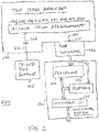
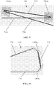
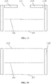
- FIG. 1 is a block diagram illustrating such a prior art TOF-MS system embodiment having orthogonal acceleration of ions for the mass analyzer, which is popular (although not dominant) in many molecular MS applications.
- the prior art TOF-MS system 50 may generally include, in series of ion process flow along the drift axis, a pulsed ion source 54 (comprising an ion source 52, ion optics 56 (optionally including one or more ion guides, not separately illustrated), and an ion accelerator 62), a time-of-flight (TOF) mass analyzer 58 having a reflectron 60 (for this example), an ion detector 64, and a computing device 68.
- a pulsed ion source 54 comprising an ion source 52, ion optics 56 (optionally including one or more ion guides, not separately illustrated), and an ion accelerator 62
- TOF time-of-flight
- Sample molecules or atoms are introduced into the ion source 52, and the ion source 52 produces ions from sample molecules or atoms and transmits the ions to the ion optics 56, which in turn focus the ions as an ion beam (or stream) 66 and transmit the ions to the ion accelerator 62.
- the ion optics 56 may perform additional ion processing functions such as compressing the ion beam, and/or thermalizing (cooling) the ions, for example.
- the ions are generally injected as a pulse or packet of ions 70 (using ion accelerator 62), orthogonally to the drift direction (in this case) and toward the reflectron 60.
- the ions are reflected (generally about 180 degrees) by the reflectron 60 and travel to the ion detector 64, having dispersed based on differing flight times (due to their differing mass-to-charge (m/z) ratios).
- the ion detector 64 generates a signal, based upon arrival times and/or arrival locations, that is then utilized by the computing device 68 to calculate actual times-of-flight from which m / z ratios are correlated, and provide a mass spectrum descriptive of the sample molecules as appreciated by persons skilled in the art.
- a significant problem with these various prior art TOF-MS systems is a potentially large variance in the kinetic energies of the ions generated by the ion source 52.
- ions having the same masses but differing kinetic energies will have different arrival times at the ion detector 64.
- there will be a significant spread of arrival times providing a comparatively wide peak with large tails in the mass spectrum, and potentially obscuring and interfering with detection of ions of nearby masses.
- the reflectron TOF-MS was developed from the earlier linear TOF-MS design to compensate for broad ion kinetic energy distributions, although the reflectron does not fully resolve this problem.
- mass resolving power defined in any TOF-MS as T / ⁇ T
- T / ⁇ T the time-of-flight " T " from the ion source to the detector, as divided by the width of the mass spectrum at one-half the maximum (“ ⁇ T ")
- ⁇ T " the time-of-flight " from the ion source to the detector, as divided by the width of the mass spectrum at one-half the maximum
- ⁇ T a larger variance of kinetic energies generates a larger ⁇ T , due to the corresponding spreading of velocities and flight arrival times, decreasing mass resolving power, and also decreasing the signal-to-noise ratio ("SNR").
- Excessive ion kinetic energy distributions can also reduce the mass accuracy, defined as the deviation in the calculated mass from the actual mass of a measured ion.
- the document US 2006/163469 A1 discloses various options for arranging TOF-MS apparatuses comprising multiple mirrors. The document does not disclose to arrange the mirrors to have an intermediate TOF focus or to place an ion detector in the output TOF focus.
- a TOF-MS apparatus and system should also provide for selectable or configurable time-of-flight " T " and TOF focusing in various system embodiments, and may include multiple TOF focuses and tandem operation.
- Such a TOF-MS apparatus and system should also selectively preserve spatial information in the ion beam at detection, to allow for stigmatic imaging.
- such a TOF-MS apparatus and system should be capable of multimode operation, to selectively operate or configure the TOF-MS apparatus and system for these various features and in various combinations.
- the representative embodiments of the present invention provide numerous advantages.
- the representative apparatus and system embodiments using a selected electrostatic mirror prism arrangement of a plurality of representative electrostatic mirror prism arrangements, can select and/or control the kinetic energies of the ions comprising the (pulsed) ion beam, to create an ion beam having a selectable and comparatively narrow band of kinetic energies.
- Various representative apparatus and system embodiments also provide for selectable or configurable time-of-flight and TOF focusing, and may include multiple TOF focuses and tandem operation. Such representative apparatus and system embodiments also selectively preserve spatial information in the ion beam at detection, to allow for stigmatic imaging.
- representative apparatus and system embodiments are capable of multimode operation, to selectively operate or configure the representative apparatus and system embodiments for these various features and in various combinations.
- representative apparatus and system embodiments provide for both ultra-high mass resolution and significantly improved accuracy compared to other TOF-MS devices.
- a representative embodiment of a mass analyzing system for time-of-flight ("TOF") mass spectrometry analysis is disclosed, with the representative system embodiment coupleable to a pulsed ion source providing a first, pulsed ion beam having an input TOF focus.
- a representative system embodiment comprises: an electrostatic mirror prism arrangement coupled to an ion detector, with the electrostatic mirror prism arrangement comprising: a first electrostatic mirror prism having a first plurality of electrodes to generate a first retarding electric field to reflect the first ion beam and provide a second, intermediate ion beam having a spatial dispersion of ions proportional to ion kinetic energies, the second ion beam having an intermediate second
- the TOF focus and a second electrostatic mirror prism spaced apart from the first electrostatic mirror prism by a first predetermined distance and further arranged to have a predetermined first angular offset from the first electrostatic mirror prism, the second electrostatic mirror prism having a second plurality of electrodes to generate a second retarding electric field to reflect the second ion beam and converge the spatial dispersion of ions to provide a third, recombined ion beam, the third ion beam having a third output TOF focus; and the ion detector arranged at the output TOF focus to receive the third ion beam, the ion detector adapted to detect a plurality of ions of the third ion beam.
- the detector may be further adapted to detect ion impact position on the detector surface to generate a stigmatic image of a cross-section of the third ion beam.
- the predetermined first angular offset may be ninety degrees. In another representative embodiment, the predetermined first and second angular offsets may each be greater than or equal to 45° and less than or equal to 135°.
- the third, recombined ion beam has cancelled the spatial dispersion of ions of the second, intermediate ion beam.
- the electrostatic mirror prism arrangement may further comprise: a bandpass filter having a moveable energy bandpass control slit, the bandpass filter arranged at the intermediate TOF focus to selectively allow propagation of ions of the second ion beam having a selected range of ion kinetic energies.
- the first plurality of electrodes and the second plurality of electrodes each comprises: a first, front electrode having a first, ground electrical potential; a second electrode having a second electrical potential; and a third, rear electrode having a third electrical potential.
- each electrode of the first plurality of electrodes and the second plurality of electrodes comprise at least one electrode type selected from the group consisting of: a grid electrode, a solid electrode, a solid electrode having a central opening, and combinations thereof.
- the electrostatic mirror prism arrangement may further comprise: a first reflectron arranged spaced apart from the first electrostatic mirror prism in a first direction; and a second reflectron arranged spaced apart from the second electrostatic mirror prism in a second direction opposite the first direction; wherein the first and second reflectrons each have a corresponding central axis, the first and second reflectrons further arranged with each central axis aligned and coextensive with the second ion beam.
- the second ion beam is reflected between the first and second reflectrons to provide a selectable number of reflections proportional to a selected time-of-flight.
- Such a representative embodiment may further comprise: a processor coupled to the electrostatic mirror prism arrangement, the processor adapted to control on and off states of the first and second electrostatic mirror prisms to determine the number of reflections between the first and second reflectrons in response to the selected time-of-flight.
- a processor coupled to the electrostatic mirror prism arrangement, the processor adapted to control on and off states of the first and second electrostatic mirror prisms to determine the number of reflections between the first and second reflectrons in response to the selected time-of-flight.
- the second electrostatic mirror prism when the second electrostatic mirror prism is in an on state, the second ion beam is reflected to provide the third ion beam.
- the electrostatic mirror prism arrangement further comprises: a third electrostatic mirror prism having a third plurality of ion-transparent electrodes to generate a third retarding electric field to reflect the first ion beam or a seventh ion beam and provide a fourth ion beam having a spatial dispersion of ions proportional to ion kinetic energies, the fourth ion beam having a fourth TOF focus; a fourth electrostatic mirror prism spaced apart from the third electrostatic mirror prism by a second predetermined distance and further arranged to have a predetermined second angular offset from the third electrostatic mirror prism, the fourth electrostatic mirror prism having a fourth plurality of electrodes to generate a fourth retarding electric field to reflect the fourth ion beam and converge the spatial dispersion of ions to provide a fifth, recombined ion beam, the fifth ion beam having a fifth TOF focus; a fifth electrostatic mirror prism having a fifth plurality of electrodes to generate a fifth retarding
- the first ion beam is transmitted to the first electrostatic mirror prism.
- the seventh ion beam is transmitted to the first electrostatic mirror prism.
- the fourth electrostatic mirror prism, the fifth electrostatic mirror prism, and the sixth electrostatic mirror prism are in an on state
- the fourth, fifth, sixth and seventh ion beams are generated cyclically to provide a selectable number of reflections proportional to a selected time-of-flight.
- Such a representative embodiment may further comprise: a processor coupled to the electrostatic mirror prism arrangement, the processor adapted to control the on and off states of the third and sixth electrostatic mirror prisms to determine the number of reflections in response to the selected time-of-flight.
- the time-of-flight may be user selectable to provide predetermined levels of a mass resolving power and a signal-to-noise ratio.
- the first electrostatic mirror prism, the second electrostatic mirror prism, the third electrostatic mirror prism, the fourth electrostatic mirror prism, the fifth electrostatic mirror prism, and the sixth electrostatic mirror prism may be coplanar in an energy dispersion plane.
- TOF time-of-flight
- Such a representative system embodiment comprises: an electrostatic mirror prism arrangement coupled to an ion detector, with the electrostatic mirror prism arrangement comprising: a first electrostatic mirror prism having a first plurality of electrodes to generate a first retarding electric field to reflect the first ion beam and provide a second, intermediate ion beam having a spatial dispersion of ions proportional to ion kinetic energies, the second ion beam having an second, intermediate TOF focus; a second electrostatic mirror prism spaced apart from the first electrostatic mirror prism by a first predetermined distance and further arranged to have a predetermined first angular offset from the first electrostatic mirror prism, the second electrostatic mirror prism having a second plurality of electrodes to generate a second retarding electric field to reflect the second ion beam and converge the spatial dispersion of ions to provide a third, recombined ion beam, the third ion beam having a third TOF focus; a third electrostatic mirror prism having a third plurality of
- Such a representative embodiment may further comprise: a dissociation device adapted to generate a laser beam or an electron beam to fragment molecules of the third ion beam at the third TOF focus.
- Such a representative embodiment may further comprise: a processor coupled to the dissociation device, the processor adapted to control the on and off states of the dissociation device to selectively fragment molecules of the third ion beam at the third TOF focus.
- the processor may be further adapted to turn the dissociation device on or off at a selected duty cycle to provide a tandem operating mode for mass spectra having a plurality of fragment molecules and mass spectra having fragment-free molecules.
- the electrostatic mirror prism arrangement may further comprise: a first bandpass filter having a moveable energy bandpass control slit, the first bandpass filter arranged at the second, intermediate TOF focus to selectively allow propagation of ions of the second ion beam having a first selected range of ion kinetic energies; and a second bandpass filter having a moveable energy bandpass control slit, the bandpass filter arranged at the fourth, intermediate TOF focus to selectively allow propagation of ions of the fourth ion beam having a second selected range of ion kinetic energies
- the first electrostatic mirror prism, the second electrostatic mirror prism, the third electrostatic mirror prism, and the fourth electrostatic mirror prism may be coplanar in an energy dispersion plane.
- the third electrostatic mirror prism and the fourth electrostatic mirror prism may not be coplanar with the first electrostatic mirror prism and the second electrostatic mirror prism.
- TOF time-of-flight
- Such a representative system embodiment comprises: a plurality of pairs of electrostatic mirror prisms, a bandpass filter, and an ion detector, with each pair of electrostatic mirror prisms of the plurality of pairs of electrostatic mirror prisms comprising: a first electrostatic mirror prism having a first plurality of electrodes to generate a first retarding electric field to reflect the first ion beam or a next recombined ion beam and provide an intermediate ion beam having a spatial dispersion of ions proportional to ion kinetic energies, the intermediate ion beam having a intermediate TOF focus; and a second electrostatic mirror prism spaced apart from the first electrostatic mirror prism by a first predetermined distance and further arranged to have a predetermined first angular offset from the first electrostatic mirror prism, the second electrostatic mirror prism having a second plurality of electrodes to generate a second retarding electric field to reflect the intermediate ion beam and converge the spatial dispersion of ions to provide the next recombine
- the representative embodiments of a TOF-MS apparatus 100, 100A and system 200, 200A using a selected electrostatic mirror prism arrangement of a plurality of representative electrostatic mirror prism arrangements, can select and/or control the kinetic energies of the ions comprising the (pulsed) ion beam, to create an ion beam having a selectable and comparatively narrow band of kinetic energies.
- Such embodiments of a TOF-MS apparatus 100, 100A and system 200, 200A also provide for selectable or configurable time-of-flight and TOF focusing in various system embodiments, and may include multiple TOF focuses and tandem operation.
- Such embodiments of a TOF-MS apparatus 100, 100A and system 200, 200A also selectively preserve spatial information in the ion beam at detection, to allow for stigmatic imaging.
- such embodiments of a TOF-MS apparatus 100, 100A and system 200, 200A are capable of multimode operation, to selectively operate or configure the embodiments of a TOF-MS apparatus 100, 100A and system 200, 200A for these various features and in various combinations.
- such embodiments of a TOF-MS apparatus 100, 100A and system 200, 200A provide for both ultra-high mass resolution and significantly improved accuracy compared to other TOF-MS devices.
- a representative TOF-MS system 200, 200A comprises a TOF mass analyzer 100 apparatus, an ion detector 120, and a pulsed ion source 105.
- a representative TOF mass analyzer 100, 100A apparatus embodiment comprises at least one electrostatic mirror prism arrangement 145, 300, 400, 405, 410, 415, 430, 440, 450, or 500, which is coupled to the ion detector 120.
- An electrostatic mirror prism arrangement 145, 300, 400, 405, 410, 415, 430, 440, 450, 500 comprises at least two electrostatic mirror prisms 150, which are referred to herein as "mirror prisms" because each such electrostatic mirror prism 150 concurrently reflects the incoming ion beam and also disperses (or conversely, converges of focuses) the ions of the ion beam according to their kinetic energies, as discussed in greater detail below.
- a representative TOF-MS system 200, 200A may also comprise, optionally, a computing device 132 having a processor 130, a memory 125, and a network interface ("network I/F”) 135.
- each representative electrostatic mirror prism arrangement 145, 300, 400, 405, 410, 415, 430, 440, 450, 500 comprises at least two electrostatic mirror prisms 150 arranged or configured, as a pair, to be spaced apart from each other a predetermined distance "D" (which may be measured between any corresponding locations of the electrostatic mirror prisms 150) and further arranged or configured to have a predetermined angular offset " ⁇ " from each other.
- D which may be measured between any corresponding locations of the electrostatic mirror prisms 150
- ⁇ predetermined angular offset
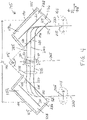
- the first electrostatic mirror prism arrangement 145 comprises at least two electrostatic mirror prisms 150, shown in FIG. 4 as a first electrostatic mirror prism 150 1 and second mirror prism 150 2 having a predetermined angular offset ⁇ of about ninety degrees.
- a representative electrostatic mirror prism arrangement 145, 300, 400, 405, 410, 415, 430, 440, 450, 500 may also comprise a bandpass filter 140 which is arranged or configured in between the first and second electrostatic mirror prisms 150 1 and 150 2 , as discussed in greater detail below.
- the various representative electrostatic mirror prism 150 arrangements 145, 300, 400, 405, 410, 415, 430, 440, 450, 500 may comprise additional electrostatic mirror prisms 150, pair-wise, in increments of two electrostatic mirror prisms 150 taken together, with the electrostatic mirror prisms 150 arranged or configured, as a pair, to be spaced apart from each other a predetermined distance "D" (190) and further arranged or configured to have a predetermined angular offset " ⁇ " (195) from each other, both of which may be the same or different between and among each such pair of electrostatic mirror prisms 150.
- D predetermined distance
- ⁇ predetermined angular offset
- any of the various representative electrostatic mirror prism arrangements 145, 300, 400, 405, 410, 415, 430, 440, 450, 500 may also comprise other components, such as one or more reflectrons 420, 425, such as illustrated and discussed below with reference to FIG. 27 .
- Any of the various representative electrostatic mirror prism arrangements 145, 300, 400, 405, 410, 415, 430, 440, 450, 500 may also comprise other components for configuring the representative TOF-MS system 200, 200A embodiments for tandem operation, such as illustrated and discussed below with reference to FIG. 29 .
- the predetermined distance "D" 190 may be measured in any way, and as illustrated, is measured along a transverse, "x" axis, from the respective centers 170 of the back (or rear) electrodes 155 of the first electrostatic mirror prism 150 1 and second mirror prism 150 2 .
- the predetermined angular offset ⁇ 195 also may be measured in any way, and as illustrated, is measured along a transverse x-y plane, using lines extending from the respective front planes or first (or front) electrodes 165 (or equivalently, from the third or rear electrodes 155) of the first electrostatic mirror prism 150 1 and second mirror prism 150 2 . As illustrated in FIG.
- the predetermined angular offset ⁇ between the first electrostatic mirror prism 150 1 and second mirror prism 150 2 is about ninety degrees (90°), for example and without limitation, with other predetermined angular offsets illustrated and discussed below with reference to FIGs. 9-11 and 26 .
- the electrostatic mirror prisms 150 are right angle ion mirror prisms ("RAIMPs"), which has maximized energy filtering functionality because their ability to disperse ions with different kinetic energies in space across a bandpass filter 140 is the highest among electrostatic mirror prism arrangements 145, 300, 400, 415, 430, 450, 500 with other angular offsets ⁇ .
- RAIMPs right angle ion mirror prisms
- the representative TOF mass analyzer 100, 100A apparatus embodiments allow the ions to travel to the ion detector 120, with corresponding masses determined based on differing flight times (due to their differing mass-to-charge (m/z) ratios).
- the ion detector 120 typically together with other processing devices such as a programmed processor 130, as a detection system) measures ion signal intensities (i.e., counts the ions) and records the time that each ion arrives at (impacts) the ion detector 120. In some embodiments, the ion detector 120 will also measure and record the location of ion impacts.
- the representative TOF mass analyzer 100, 100A apparatus is operated at a multi-pulsing (or multiplexing) rate, with multiple packets of ions provided as the first, incoming ion beam 220.
- Such an ion detector 120 may be implemented as known in the MS arts.
- the ion detector 120 produces an ion signal that is then utilized by a processor 130 to calculate actual times-of-flight from which m / z ratios are correlated, and construct a mass spectrum descriptive of the sample atoms and molecules, as appreciated by persons skilled in the art.
- the ion detector 120 such as MCP plate or electron multiplier, does not detect arrival times but detects ion currents.
- the arrival times are detected by data acquisition hardware such as time-to-digital converter or signal digitizer, such as embodied within a processor 130. This hardware works with the ion currents amplified by the ion detector 120.
- the ion detector 120 is a multi-channel ion detector, which may be position-sensitive, such as for use in the stigmatic imaging capability discussed below.
- a multi-channel ion detector is configured for collecting and measuring the flux (or current) of mass-discriminated ions over a plurality of channels, with each channel, or pixel, corresponding to a discrete detection area or spot on the detector face.
- Such an ion detector 120 is capable of detecting the impact of an ion at that detection spot and converting it into an independent electron shower, whose current to the electron collector (anode) can be measured as an electrical signal.
- An example of a multi-channel detector is a micro-channel plate (MCP) detector.
- MCP micro-channel plate
- an ion detector 120 When provided as a position-sensitive ion detector, such as an ion detector 120 (based on MCP technology) is capable of making multiple independent measurements at multiple positions on the electron collector, and thus generating independent measurement signal outputs for each detection (ion impact) spot.
- the ion detector 120 can be an electron multiplier (EM) optimized for TOF-MS applications.
- EM electron multiplier
- a representative TOF-MS system 200, 200A may further comprise a pulsed pulsed ion source 105 (which may optionally include any ion optics, ion guides or ion accelerators), which provides a first or primary ion beam 220 to the TOF mass analyzer 100, 100A.
- a pulsed pulsed ion source 105 which may optionally include any ion optics, ion guides or ion accelerators, which provides a first or primary ion beam 220 to the TOF mass analyzer 100, 100A.
- the ion source embodiment which generates the ions may be any type of continuous-beam or pulsed ion source suitable for producing analyte ions for spectrometry, although as provided to the TOF mass analyzer 100, 100A, the first or primary ion beam 220 is comprised of a one or more pulses or packets of ions, i.e., is a pulsed ion beam, which may be implemented using any mechanism, such as known pulsed ion extraction optics or modulation. Depending on the type of ionization implemented, the pulsed ion source 105 may be arranged in a vacuum chamber or may operate at or near atmospheric pressure.
- Typical ion sources 105 may include, for example and without limitation, electron ionization (EI) sources, chemical ionization (CI) sources, photo-ionization (PI) sources, electrospray ionization (ESI) sources, atmospheric pressure chemical ionization (APCI) sources, atmospheric pressure photo-ionization (APPI) sources, field ionization (FI) sources, plasma or corona discharge sources, laser desorption ionization (LDI) sources, and matrix-assisted laser desorption ionization (MALDI) sources.
- EI electron ionization
- CI chemical ionization
- PI photo-ionization
- APCI atmospheric pressure chemical ionization
- APPI atmospheric pressure photo-ionization
- FI field ionization
- plasma or corona discharge sources plasma or corona discharge sources
- LLI laser desorption ionization
- MALDI matrix-assisted laser desorption ionization
- the pulsed ion source 105
- a pulsed ion source 105 also generally may include any ion optics or ion guides, such as those described as examples in greater detail below.
- the representative TOF-MS system 200, 200A embodiments may further comprise a computing device 132 having a processor 130, a memory 125, and a network interface 135, such as those described as examples in greater detail below.
- the processor 130 is adapted to or configured for control, monitor and/or time various functional aspects of the TOF-MS system 200, 200A described herein, such as for multimode operations and for use in selecting and controlling the time-of-flight " T ".
- Such a computing device 132 may be, or be embodied in, for example and without limitation, a network computer, a mainframe computer, a desktop computer, laptop computer, portable computer, tablet computer, handheld computer, mobile computing device, personal digital assistant (PDA), smartphone, and so on.
- the processor 130 may also control all voltage sources (not separately illustrated), as well as timing controllers, clocks, frequency/waveform generators and the like as needed for applying voltages to various components of the TOF-MS system 200, 200A, including voltages applied to electrostatic mirror prisms 150 and other components of representative electrostatic mirror prism arrangements 145, 300, 400, 405, 410, 415, 430, 440, 450, 500, as described below.
- the processor 130 may also be adapted or configured to receive the ion detection signals from the ion detector 120 and perform tasks relating to data acquisition and signal analysis as necessary to generate chromatograms, drift spectra, and mass (m/z ratio) spectra characterizing the sample under analysis.
- the processor 130 may also be adapted or configured to apply mass calibration methods and calculating ion mass, as known in the art.
- the processor 130 may also be adapted or configured to control a user interface (not separately illustrated) that provides screen displays of spectrometric data and other data and receives user input, for example and without limitation.
- the computing device 132 via network I/F 135, may be in communication with various components of the TOF-MS system 200, 200A via wired or wireless communication links. The various components of the computing device 132 are also discussed in greater detail below.
- the pulsed ion source 105 all that is required of the pulsed ion source 105 is that it generate a pulsed ion beam which is provided to the TOF mass analyzer 100, 100A as a first or primary (pulsed) ion beam 220, without any kinetic energy filtering being required.
- the first or primary ion beam 220 may be and generally is comprised of a plurality of ions, in packets or pulses, having a wide range of kinetic energies.
- Each of the electrostatic mirror prisms 150 when turned on and electrostatically biased to deflect ions, provides a retarding electric field using corresponding voltages applied to the electrodes 155, 160, 165 of the electrostatic mirror prisms 150.
- the electrostatic mirror prisms 150 may use at least one ion-transparent electrode 160 (e.g., a grid or gridless and having an opening 312) to separate the field into at least two different regions, as illustrated in FIGs. 4 and 6 , with a first region 236 having an electric field with a first gradient (illustrated using line 221 in FIG.
- the electrostatic mirror prisms 150 may be gridless, as illustrated for various embodiments discussed below.
- the description of how the electrostatic mirror prisms 150 operate uses a comparatively simple geometry with two electrodes 155, 160, having applied voltages and the first, front electrode 165 having a ground potential.
- a first (and lowest) voltage 224 (having a voltage level "H", such as a ground potential (zero)) is applied to the first, front electrode 165 (illustrated in cross-section in FIG.
- a second voltage 226 (having a voltage level "I") is applied to the second, middle electrode 160 (also illustrated in cross-section in FIG. 4 as a grid electrode), and a third (highest) voltage 228 (having a voltage level "J") is applied to the third, back electrode 155 (illustrated in cross-section in FIG. 4 as a solid, planar electrode).
- a third (highest) voltage 228 (having a voltage level "J") is applied to the third, back electrode 155 (illustrated in cross-section in FIG. 4 as a solid, planar electrode).
- one or more additional voltages will be applied to each corresponding intermediate electrode (i.e., any one or more electrodes located between the first and back electrodes 165, 155).
- Known structures such as a resistive voltage divider, may be utilized to supply these different voltages to the various electrodes of the electrostatic mirror prisms 150, with the corresponding voltages and electrode shapes, configurations and layouts utilized to shape the resulting electric field.
- the various electrodes 155, 160, 165 may be separated from each other by resistors or other resistive components, and further are typically electrically isolated from any housing or enclosure (typically provided at a ground potential), such as using various insulators or other dielectric materials.
- the electrostatic mirror prisms 150 such as configured as right angle ion mirror prisms, based on a set of several closely positioned electrodes 155, 160, 165 are utilized for several purposes, namely, for ion deflection, for time-of-flight focusing (e.g., within a TOF-MS analyzer 100), and further for separation of ions over kinetic energies (e.g., as electrostatic prisms).
- the geometry of the electrostatic mirror prisms 150 may be planar/rectangular, e.g. in the shape of a rectangular box, a parallelepiped, a trapezoid ( FIGs.
- a first or primary ion beam 220 may enter the first electrostatic mirror prism 150 1 at a 45° angle of incidence from the normal to the retarding electric field plane, for example and without limitation.
- the first or primary ion beam 220 resembles an event of "ion ricochet" from this retarding electric field plane, and the main axis of symmetry of the first electrostatic mirror prism 150 1 may be turned by 45° with respect to that of the first or primary ion beam 220 provided by the pulsed ion source 105.
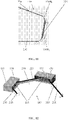
- the electrostatic mirror prisms 150 operate as an ion mirror, and instead of reflecting ions back within a rather sharp angle, as reflectrons do, the electrostatic mirror prisms 150 deflect the ion beams by certain angles depending on the sector angle and the kinetic energies of the ions. As illustrated for the configurations of FIGs. 3 and 4 , the electrostatic mirror prisms 150 deflect ions by a 90° angle, thereby acting as a right angle ion mirror. At the same time, the first electrostatic mirror prism 150 1 separates the reflected ions into spatially resolved parallel beams corresponding to their kinetic energies, thereby acting as an electrostatic prism. This configuration of the electrostatic mirror prisms 150 enables new capabilities and functionalities in TOF-MS analysis.
- the first or primary ion beam 220 enters the TOF mass analyzer 100, 100A and has a first, input (or initial) TOF focus (or focal plane) 205, namely, a point of simultaneous arrival of ions of the same mass and charge but with different kinetic energies, i.e., an ion packet origination plane.
- the first or primary ion beam 220 enters the first electrostatic mirror prism 150 1 and is deflected (in this case by 90°) to form a second or secondary ion beam 225, which has a second (or secondary) TOF focus (or focal plane) 210.
- the ions comprising the second or secondary ion beam 225 have been spatially-dispersed and separated into different bands having different kinetic energies, illustrated in FIG. 4 as kinetic energy bands 235, 240, 245.
- the bandpass filter 140 may be placed at the second TOF focus 210.
- the second or secondary ion beam 225 enters the second electrostatic mirror prism 150 2 and is deflected (in this case also by 90°) to form a third or tertiary ion beam 230, which has a third, output TOF focus (or focal plane) 215.
- the spatially-dispersed ions (according to their kinetic energies) comprising the second or secondary ion beam 225 have now been recombined and/or converged into the third or tertiary ion beam 230 (in which the ions are no longer spatially-dispersed according to their kinetic energies), with spatial information of the ions (of the first or primary ion beam 220) preserved in the third or tertiary ion beam 230.
- An ion detector 120 is typically placed at this third TOF focus 215 to detect the arrival times (and/or positions) of the ions of the third or tertiary ion beam 230.
- an ion detector 120 is placed at the last such TOF focus, which provides the same functionality as the third TOF focus 215.
- first and third ion beams 220, 225, 230 are illustrated, from regions 175, 180, and 185 of FIG. 4 .
- the first and third ion beams 220, 230 are generally collimated beams, having generally circular cross-sections, with any spatial information of the first or primary ion beam 220 preserved or maintained in the third or tertiary ion beam 230.
- FIG. 5A the first and third ion beams 220, 230 are generally collimated beams, having generally circular cross-sections, with any spatial information of the first or primary ion beam 220 preserved or maintained in the third or tertiary ion beam 230.
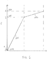
- the ions forming the second or secondary ion beam 225 has been spatially-dispersed or spread according to their respective kinetic energies, with: (1) those ions having higher energies having entered deeper into and remained a longer period of time within the first electrostatic mirror prism 150 1 , exiting as kinetic energy band 245 of the second or secondary ion beam 225; (2) those ions having lesser energies having entered less deeply into and remained a shorter period of time within the first electrostatic mirror prism 150 1 , exiting as kinetic energy band 240 of the second or secondary ion beam 225; and (3) those ions having even lower or the least energies having entered less or least deeply into and remained a shorter or least period of time within the first electrostatic mirror prism 150 1 , exiting as kinetic energy band 235 of the second or secondary ion beam 225.
- the second or secondary ion beam 225 has been illustrated as having three spatially-dispersed energy bands 235, 240, 245 for ease of explanation only, and those having skill in the art will recognize that the second or secondary ion beam 225 comprises a continuous spectrum of kinetic energies. Any specific separation of the second or secondary ion beam 225 into individuated kinetic energy bands 235, 240, 245 (or more kinetic energy bands) may be user selectable and determined using the bandpass filter system 140.
- the two electrostatic mirror prisms 150 forming the pair, and the trajectories of ions passing from the first, input TOF focus 205 through the second (intermediate) TOF focus 210 to the third, output TOF focus 215 are generally in the same plane in order to enable the cancellation of chromatic aberrations.
- the spatial dispersion of ions with different energies, in the second or secondary ion beam 225, in the region between the electrostatic mirror prisms 150 occurs in the same plane called an "energy dispersion plane", illustrated in cross-section in FIG. 5B .
- the second (or intermediate) TOF focus 210 provides a desired location to arrange or install a bandpass filter 140, e . g ., having an energy bandpass control slit (aperture or opening) 255 (which may be adjustable) as illustrated in FIG. 8 , to cut off ions with undesired energies and thus suppress "tails" of TOF mass spectral peaks and filter out low energy ions formed due to fragmentation or multiple scattering along the ion flight path.
- the energy bandpass control slit 255 has an adjustable and/or moveable width (e.g.
- first and second moveable plates 142 may have a moveable position, both of which may be adjusted manually (such as using a micrometer), or automatically by a vacuum or a motor 144 (such as a servomotor), to control the slit 255 width and position of the bandpass filter 140), such as under the control of the processor 130 and configurable within the bandpass filter 140, e.g., to increase or decrease the width 146 of the energy bandpass control slit 255 and/or to move the filter 140, and correspondingly select more or less of the second or secondary ion beam 225.
- the moveable plates 142 are utilized, each comprised of solid molybdenum functioning as "knife edges".
- These moveable plates 142 form a slit 255 whose width and position can be precisely adjusted, as follows: (1) moving the moveable plates 142 apart opens the slit 255 and vice-versa, while (2) moving the moveable plates 142 in the same direction translates its position at the intermediate TOF focus 210 with respect to the ion beam, such as for selecting one or more of the kinetic energy bands 235, 240, 245 or parts thereof, with or without extending the width of the slit 255.
- a bandpass filter 140 (having an energy bandpass control slit 255 with adjustable width 146, and also possibly moveable, depending upon the selected embodiment) permits selecting an optimally narrow or wider range of ion energies, such as selecting one or more of the kinetic energy bands 235, 240, 245 or parts thereof. This serves to improve the signal-to-noise ratio and the effective mass resolution of the representative TOF mass analyzer 100, 100A apparatus and TOF-MS system 200, 200 embodiments. Various examples are illustrated and discussed in greater detail below.
- representative bandpass energy filtering of the second or secondary ion beam 225 for representative TOF mass analyzer 100, 100A apparatus embodiments is illustrated in FIG. 21 , in which the ions having the highest and lowest kinetic energizes are filtered out, and only the ions having the more intermediate kinetic energies (in band 240) pass through the bandpass filter 140.
- representative bandpass energy filtering of the second or intermediate ion beams 225, 340 for representative TOF mass analyzer 100, 100A apparatus embodiments is illustrated in FIG.
- the ions penetrate into the retarding electric field region of the electrostatic mirror prisms 150, being decelerated until about half of their initial energy at the deepest point and then accelerating back to the same energy at the exit point.
- the trajectory of ions in the retarding field resembles a quarter of a circle, for some electrostatic mirror prisms 150 (and depending upon their configurations and applied voltages), for example, whose radius depends on dimensions of the electrostatic mirror prisms 150 and potentials applied to its electrodes 155, 160, 165.
- the dimensional and electrical configuration of the section between the middle electrode (grid) 160 and the back electrode (plate) 155 may be important. For the same dimensions and potential distributions, ions with different energies will have different turn radii but, importantly, the same turn angle of 90°.
- a collimated beam of ions with different kinetic energies originates from a plane corresponding to the first or initial TOF focus 205 (e.g., zero time) and perpendicular to its motion towards the first electrostatic mirror prism 150 1 , then, after passing through the first electrostatic mirror prism 150 1 with the higher kinetic energy ions having higher velocities but spending more time in the first electrostatic mirror prism 150 1 and the lower kinetic energy ions having lower velocities but exiting the first electrostatic mirror prism 150 1 earlier (sooner), these ions flying as parallel beams will create, at a certain time and distance, a second or secondary TOF focus 210, i.e., a plane perpendicular to their motion out of the first electrostatic mirror prism 150 1 , which they will cross at (about) the same time.
- a second or secondary TOF focus 210 i.e., a plane perpendicular to their motion out of the first electrostatic mirror prism 150 1 , which they will cross at
- the first or initial TOF focus (or plane) 205 and the secondary TOF focus (or plane) 210 will be orthogonal to each other.
- the position of the second or secondary TOF focus 210 will depend on (median) ion beam energy and may be controlled by choosing appropriate dimensions and potential distributions for the first electrostatic mirror prism 150 1 . With the same fixed potentials, the larger these dimensions of the first electrostatic mirror prism 150 1 , then the second or secondary TOF focus 210 should be a greater distance away from the first electrostatic mirror prism 150 1 . With the same fixed dimensions, smaller adjustments of the position of the second or secondary TOF focus 210 may be done by varying the potentials of the middle electrode 160 and the back electrode (plate) 155.
- the apparatus 100, 100A and the system 200, 200A can also work with imperfectly collimated (i.e. slightly diverging or converging) input or incoming ion beams.
- imperfectly collimated i.e. slightly diverging or converging
- the more divergent the input or incoming ion beam is the more astigmatism will be seen in the ion imaging capability.
- This astigmatism does not cancel the TOF focusing capability, which is only just slightly deteriotated.
- the apparatus 100, 100A and the system 200, 200A are applicable to both perfectly collimated (parallel) and imperfectly (slightly diverging or converging) ion beams.
- sector field analyzers are based on some kind of a capacitor design (cylindrical, spherical, toroidal etc.), and the voltages applied to opposite electrode plates of the capacitor are symmetric with respect to ground potential. Therefore, ions passing through sector field analyzers along the central trajectory do not experience significant deceleration and acceleration, with only minor contribution of these processes for trajectories slightly off central. Thus almost no flight time is spent for deceleration/acceleration, and it is mostly the difference in trajectory lengths, which drives the TOF focusing by sector field analyzers.
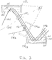
- each pair of electrostatic mirror prisms 150 for the representative electrostatic mirror prism arrangements 145, 300, 400, 405, 410, 415, 430, 440, 450, 500 such as the first and second electrostatic mirror prisms 150 1 , and 150 2 , are arranged symmetrically, having a symmetry plane 305 orthogonal to the trajectories of the ions of the second or secondary ion beam 225 and located in the region of the second or secondary (or intermediate) TOF focus 210, as illustrated in FIG. 4 .
- this symmetry plane 305 passes precisely through the second or intermediate TOF focus 210, then the location of the third, output TOF focus 215 will be symmetrical to and mirror the location of the first, input TOF focus 205. If the symmetry plane 305 is shifted away from the second TOF focus 210, then the third, output TOF focus 215 will be correspondingly shifted from the mirror location of the first, input TOF focus 205.
- the second electrostatic mirror prism 150 2 is located opposite the first electrostatic mirror prism 150 1 on the other side of this symmetry plane 305, spatially dispersed parallel ion beams with different kinetic energies in the second or secondary ion beam 225 enter the second electrostatic mirror prism 150 2 with same spatial dispersion of kinetic energies. Due to interactions of the ions with the retarding electric field of this second electrostatic mirror prism 150 2 , the spatial dispersion is cancelled after the pass through the second electrostatic mirror prism 150 2 . This is also illustrated in FIG. 7 , in contrast with the additional spatial dispersion created when the first and second electrostatic mirror prisms 150 1 and 150 2 are arranged or configured to reflect the first or primary ion beam 220 in a typical prior art zig-zag configuration.
- the second electrostatic mirror prism 150 2A uses the symmetry discussed above, the second electrostatic mirror prism 150 2A generates a third or tertiary ion beam 230 A in which the ions having different kinetic energies are no longer spatially dispersed but are recombined and/or converged in a collimated beam, illustrated using dotted lines.
- the predetermined angular offset ⁇ should be greater than zero degrees and less than one hundred eighty degrees (i.e., 0° ⁇ ⁇ ⁇ 180°).
- the predetermined angular offset ⁇ can be more than ninety degrees, in practice, it may be limited by the ability of ions to penetrate into the retarding field regions, so that an achievable upper limit is more likely to be in the range of approximately 135 degrees. While the predetermined angular offset ⁇ can be less than ninety degrees, in practice, it also may be limited due to correspondingly lessened prismatic capability, so that in practice an achievable lower limit is more likely to be in the range of approximately 45 degrees, for example and without limitation. Again, the maximal prismatic functionality is achieved at ninety degrees, because at that predetermined angular offset ⁇ , the spatial dispersion of ions with different kinetic energies is the largest.
- any reference to the angular offsets those having skill in the art will recognize that there may be fabrication tolerances, so that any reference to a specific number of degrees will be understood to mean and include such tolerances, generally in the range of about 1° - 5°, such as a reference to 90° will mean and include 90° ⁇ 5°, for example and without limitation.
- a zig-zag multi-reflection configuration of the prior art has a point of rotational symmetry 152 located on the central ion trajectory in the middle between two opposite electrostatic mirrors, where the positional arrangement of the second electrostatic mirror 150 2B can be obtained by lateral displacement of the second electrostatic mirror prism 150 2B without rotation, or equivalently by rotating the first one (150 1 ) around this point of rotational symmetry 152 by 180°, as illustrated in FIG. 7 .
- the second electrostatic mirror prism 150 2B generates a diverging third or tertiary ion beam 230B which has even greater, amplified spatial dispersion of ions with different kinetic energies compared to the second or secondary ion beam 225.
- this amplified spatial dispersion of ions of a zig-zag configuration there is no third or output TOF focus, and stigmatic imaging is not possible.
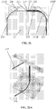
- FIGs. 9 - 11 are cross-sectional, schematic plan view diagrams illustrating a representative first or primary ion beam 220, a representative spatially-dispersed second or secondary ion beam 225, with corresponding angular offsets ⁇ of representative electrostatic mirror prisms 150 having cylindrical shapes in FIG.9 and trapezoidal shapes in FIGs. 10 and 11 , to generate a recombined and/or convergent third or tertiary ion beam 230.
- FIGs. 9, 10 , 11 , 21, 22A , 22B and 22C include ion beam trajectories (ray tracing) which were obtained using the industry standard software for mass spectrometry developers, known as SIMION 8.1 ion optics modeling software.
- FIG. 9 A representative "bow-tie" second electrostatic mirror prism arrangement 405 is illustrated in FIG. 9 , with a comparatively small predetermined angular offset ⁇ (providing comparatively minimal prismatic functionality), while FIGs. 10 and 11 illustrate larger predetermined angular offsets ⁇ , with FIG. 10 illustrating an angular offset ⁇ of less than 90° (e.g., about 80°) for a representative third electrostatic mirror prism arrangement 410, and with FIG. 11 illustrating an angular offset ⁇ of more than 90° (i.e., 90° ⁇ ⁇ ⁇ 180°) (e.g., about 100°), for a representative fourth electrostatic mirror prism arrangement 440.
- FIGs. 9-11 also illustrate the additional, available angles of incidence and reflection of the various ion beams (measured from normal to the front electrode plane) within a representative TOF mass analyzer 100, 100A apparatus embodiment, which may correlate (depending on the electric fields) with the predetermined angular offsets ⁇ , as illustrated, in addition to the 45° angles discussed above.
- the second electrostatic mirror prism 150 2 will need to be arranged or positioned with a corresponding predetermined angular offset ⁇ in order to receive the reflected, second or secondary (or intermediate) ion beam 225.
- angles allow using lower electric potentials on electrodes of the electrostatic mirror prisms 150 while preserving their reflective/retarding functionality.
- it may be more convenient to change the shape of the electrostatic mirror prisms 150 from a deep cylinder (whose height is larger than diameter, FIG. 9 ) to a more shallow cylinder (whose diameter is larger than height ( FIG. 13 ), or, alternatively, to elongate the front cross-section of the electrostatic mirror prism 150 ( i.e. plane parallel to its electrodes) and change its shape from round to oval/elliptical or rectangular (e.g., FIGs. 10 , 11 , 12 , 14 - 18 ).
- the electrostatic mirror prisms 150 may have any number and placement of electrodes, may have grid electrodes, may have solid or planar electrodes, and may have various slits or openings in the electrodes.
- the electrostatic mirror prisms 150 may have any number and placement of electrodes, may have grid electrodes, may have solid or planar electrodes, and may have various slits or openings in the electrodes.
- the electrostatic mirror prisms 150 may have any corresponding structure to achieve a desired configuration of the retarding electric field. FIG.
- FIG. 12 is an isometric diagram illustrating the representative first embodiments of rectangular (or rectangular box) electrostatic mirror prisms 150 having the first and second grid electrodes 165, 160 and a third, solid planar third or rear electrode 155, and having the representative first electrostatic mirror prism arrangement 145 for a representative TOF mass analyzer 100, 100A apparatus embodiment and a representative TOF system 200, 200A apparatus embodiment.
- FIG. 12 is an isometric diagram illustrating the representative first embodiments of rectangular (or rectangular box) electrostatic mirror prisms 150 having the first and second grid electrodes 165, 160 and a third, solid planar third or rear electrode 155, and having the representative first electrostatic mirror prism arrangement 145 for a representative TOF mass analyzer 100, 100A apparatus embodiment and a representative TOF system 200, 200A apparatus embodiment.
- each grid electrode typically comprises a series of spaced-apart, parallel and comparatively thin wires or conductors, which have a corresponding applied voltage to provide the desired electric field, while also allowing the various ions to pass through the grid electrode and move deeper into the electrostatic mirror prism 150.
- FIG. 14 is an isometric diagram illustrating representative third embodiments of trapezoidal electrostatic mirror prisms 150B, also having the first grid electrode 165B and a third, solid planar third or rear electrode 155B, with the second electrode 160 not illustrated separately in this view, and having the representative first electrostatic mirror prism arrangement 145 for a representative TOF mass analyzer 100, 100A apparatus embodiment and a representative TOF system 200, 200A apparatus embodiment.
- FIG. 15 is an isometric diagram illustrating representative fourth embodiments of gridless rectangular electrostatic mirror prisms 150C, and having the representative first electrostatic mirror prism arrangement 145 for a representative TOF mass analyzer 100, 100A apparatus embodiment and a representative TOF system 200, 200A apparatus embodiment.
- FIG. 14 is an isometric diagram illustrating representative third embodiments of trapezoidal electrostatic mirror prisms 150B, also having the first grid electrode 165B and a third, solid planar third or rear electrode 155B, with the second electrode 160 not illustrated separately in this view, and having the representative first electrostatic mirror
- 16 is an isometric diagram illustrating representative fifth embodiments of gridless, trapezoidal electrostatic mirror prisms 150D, and having the representative first electrostatic mirror prism arrangement 145 for a representative TOF mass analyzer 100, 100A apparatus embodiment and a representative TOF system 200, 200A apparatus embodiment.
- FIG. 17 is an isometric, cross-sectional diagram illustrating representative fourth embodiments of gridless, rectangular electrostatic mirror prisms 150C, and having the representative first electrostatic mirror prism arrangement 145 for a representative TOF mass analyzer 100, 100A apparatus embodiment and a representative TOF system 200, 200A apparatus embodiment.
- FIG. 18 is an isometric, cross-sectional diagram illustrating representative fifth embodiments of gridless, trapezoidal electrostatic mirror prisms 150D, and having the representative first electrostatic mirror prism arrangement 145 for a representative TOF mass analyzer 100, 100A apparatus embodiment. As illustrated in FIGs.
- each electrode 310 (except the rear electrode 155) typically comprises a planar conductor having a centrally-located opening or slit 312, which also has a corresponding applied voltage to provide the desired electric field, while also allowing the various ions to pass through the opening or slit 312 of the electrode 310 and move deeper into the electrostatic mirror prism 150C and/or 150D.
- FIG. 19 is a cross-sectional diagram illustrating a representative sixth embodiment of an electrostatic mirror prism 150E for use in any of the various electrostatic mirror prism arrangements for representative TOF mass analyzer 100, 100A apparatus embodiments and representative TOF system 200, 200A apparatus embodiments, and especially suitable for the eighth and ninth electrostatic mirror prism arrangements illustrated and discussed below with reference to FIGs. 27 and 28 .
- the electrostatic mirror prism 150E differs from the electrostatic mirror prism 150 insofar as the third, rear electrode 155E is ion-transparent: the electrostatic mirror prism 150E has a slit or opening 315 in the third, rear electrode 155E, which and allows for the ion beam (e.g., second or secondary ion beam 225 or third or tertiary ion beam 230) to pass through the electrostatic mirror prism 150E without significant disturbance when the electrostatic mirror prism 150E is off and not electrostatically biased to deflect ions.
- the ion beam e.g., second or secondary ion beam 225 or third or tertiary ion beam 230
- FIG. 20 is a cross-sectional diagram illustrating a representative seventh embodiment of an electrostatic mirror prism 150F for use in any of the various electrostatic mirror prism arrangements for representative TOF mass analyzer 100, 100A apparatus embodiments and representative TOF system 200, 200A apparatus embodiments, and especially suitable for the eighth and ninth electrostatic mirror prism arrangements illustrated and discussed below with reference to FIGs. 27 and 28 .
- the electrostatic mirror prism 150F differs from the electrostatic mirror prism 150 insofar as the third, rear electrode 155F is ion-transparent: the electrostatic mirror prism 150F has a grid configuration of the third, rear electrode 155F, which also allows for the ion beam (e.g., second or secondary ion beam 225 or third or tertiary ion beam 230) to pass through the electrostatic mirror prism 150F without significant disturbance when the electrostatic mirror prism 150F is off and not electrostatically biased to deflect ions.
- the ion beam e.g., second or secondary ion beam 225 or third or tertiary ion beam 230
- any of the gridless embodiments such as electrostatic mirror prism 150C and electrostatic mirror prism 150D, also can use these arrangements with a rear ion-transparent electrode, such as either a grid electrode or a solid electrode with an opening 315.
- electrostatic mirror prisms 150 depend both on the distance "D” separating them and on the kinetic energy of ions they reflect.
- FIGs. 22A , 22B, 22C, and 22D are diagrams illustrating representative stigmatic imaging using electrostatic mirror prisms 150, and having the representative first electrostatic mirror prism arrangement 145 for a representative TOF mass analyzer 100, 100A apparatus embodiment and a representative TOF system 200, 200A apparatus embodiment, forming a novel imaging multi-reflecction TOF-MS analyzer 100, 100A, with FIG. 22B showing the ion image of a hexagonal honeycomb pattern from the first or initial TOF focus 205 and with FIG. 22C showing the image of the same honeycomb pattern formed in the third or tertiary TOF focus 215.
- a collimated beam of ions with different kinetic energies as the first or primary ion beam 220, entering the first electrostatic mirror prism 150 1 may exit the first electrostatic mirror prism 150 1 having been dispersed or split into a set of parallel beams of ions having different kinetic energies, in second or secondary ion beam 225.
- this second or secondary ion beam 225 is directed into a second electrostatic mirror prism 150 2 whose position and orientation is arranged as a mirror reflection of the first electrostatic mirror prism 150 1 across the second or secondary TOF focus (or plane) 210, such as in representative electrostatic mirror prism arrangement 145, then the ions may exit the second electrostatic mirror prism 150 2 as a single, collimated third or tertiary ion beam 230.
- This third or tertiary ion beam 230 may form a third or tertiary TOF focus plane 215 located at the same distance from the exit of the second electrostatic mirror prism 150 2 as that between the first or initial TOF focus 205 and the entrance to the first electrostatic mirror prism 150 1 .
- this third or tertiary ion beam 230 may have a structure of an inverted ion image of the first or initial TOF focus 205 (a hexagonal honeycomb pattern in the case of FIGs. 22B and 22C , which is symmetrically inverted or flipped over or with respect to the second or secondary TOF focus 210), as indicated in FIG. 22D by arrows 213, 214 pointed opposite to each other with respect to the second or secondary TOF focus 210 or symmetry plane 305).
- the capability of the representative electrostatic mirror prism arrangement 145 to image the initial (input) TOF focus (or focal plane) 205 onto the third or tertiary (output) TOF focus (or focal plane) 215 may make it an excellent "building block” for assembly of stigmatically imaging for representative TOF mass analyzer 100 apparatus embodiments and representative TOF system 200 embodiments with ultra-high mass resolution and accuracy that are based on multiple-pass (multi-"ricochet") principles.
- multiple pairs of electrostatic mirror prisms 150 can be interfaced via these input and output TOF focuses 205, 215, as combined output-input focuses as discussed above, with the output TOF focus of every previous pair of electrostatic mirror prisms 150 serving as the input TOF focus for every next pair of electrostatic mirror prisms 150, thus creating cascade arrangements, with several examples discussed in greater detail below. Because rotating the ion image on such an interfacing (combined output-input) TOF focus plane around its center does affect TOF focusing and can be accounted for, the mutual orientation of the cascaded pairs of electrostatic mirror prisms 150 can be flexible.
- a coiled, stacked or other two- and three-dimensional space-saving geometry may be used to cascade pairs of electrostatic mirror prisms 150 and achieve large numbers of passes, increasing the time-of-flight " T " and improving mass resolving power "T / ⁇ T".
- the representative TOF mass analyzer 100 apparatus embodiments may also be compatible with orthogonal acceleration TOF-MS arrangements, such as the one exemplified in FIG. 1 .
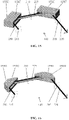
- FIG. 23 is an isometric diagram illustrating a representative fifth electrostatic mirror prism arrangement 300 having representative electrostatic mirror prisms 150D in a first cascaded arrangement or configuration for a representative TOF mass analyzer 100 apparatus embodiment and a representative TOF system 200 embodiment.
- FIG. 24 is a cross-sectional diagram illustrating the representative fifth electrostatic mirror prism arrangement 300 having representative electrostatic mirror prisms 150D having the first cascaded arrangement or configuration for the representative TOF mass analyzer 100 apparatus embodiment and the representative TOF system 200 embodiment of FIG. 23 .
- the electrostatic mirror prisms 150 are arranged pair-wise, in groups of two electrostatic mirror prisms 150. As illustrated in FIGs.
- electrostatic mirror prisms 150D have been cascaded, i.e., arranged serially, with a first electrostatic mirror prism 150D 1 paired with a second electrostatic mirror prism 150D 2 , with a third electrostatic mirror prism 150D 3 paired with a fourth electrostatic mirror prism 150D 4 , and with a fifth first electrostatic mirror prism 150D 5 paired with a sixth electrostatic mirror prism 150D 6 .
- the output TOF focus of one pair of electrostatic mirror prisms 150 becomes the input TOF focus of the next pair of electrostatic mirror prisms 150, as combined output-input focuses.
- This representative fifth electrostatic mirror prism arrangement 300 is an example of multi-reflection (cascade) electrostatic mirror prism 150 TOF-MS design using three pairs of gridless electrostatic mirror prisms 150D. All three pairs of electrostatic mirror prisms 150 lie in the same "energy dispersion plane", and there are seven TOF focuses as mentioned above: the input focus 205 (from a pulsed ion source 105 or intervening components), three "intermediate” focuses for spatially dispersed ions of different energies (210, 320, 330), two combined output-input focuses (215, 325) to interface between the pairs or sets of electrostatic mirror prisms 150 (the first pair with the second pair, and the second pair with the third pair, as illustrated), and the last output focus 335 where an ion detector 120 can be placed.
- a first or primary ion beam 220 (having a first or initial TOF focus 205) is input into the first electrostatic mirror prism 150D 1 , which generates a second or intermediate (i.e., spatially-dispersed) ion beam 225 (having a second or secondary TOF focus 210) to the second electrostatic mirror prism 150D 2 , which generates a third or tertiary ion beam 230 (having a third or tertiary TOF focus plane 215, as a combined output-input focus).
- the third or tertiary ion beam 230 is input into the third electrostatic mirror prism 150D 3 , which generates a next intermediate (i.e., spatially-dispersed) ion beam 340 (having an intermediate TOF focus 320) provided to the fourth electrostatic mirror prism 150D 4 , which generates another ion beam 345 (having a TOF focus plane 325, as another combined output-input focus), which in turn is provided to the third pair of electrostatic mirror prisms 150D and is input into the fifth electrostatic mirror prism 150D 5 , which generates a next intermediate (i.e., spatially-dispersed) ion beam 350 (having an intermediate TOF focus 330) provided to the sixth electrostatic mirror prism 150D 6 , which generates another, output ion beam 355 (having an output TOF focus plane 335).
- a next intermediate (i.e., spatially-dispersed) ion beam 340 having an intermediate TOF focus 320
- an ion detector 120 is typically positioned at this output TOF focus plane 335, and together with the representative electrostatic mirror prism arrangement 300, forms another representative TOF mass analyzer 100 apparatus embodiment.
- the time-of-flight " T " has been increased 3-fold, while the width of the mass spectrum at one-half the maximum " ⁇ T " has changed insignificantly due to multiple TOF focusing events, thus considerably increasing the mass resolving power.
- the implementation of bandpass energy filtering may be implemented as described above, at any or at all of the three intermediate focuses 210, 320, 330 for spatially dispersed ions of different energies will further narrow " ⁇ T " and further improve mass resolution.
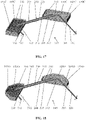
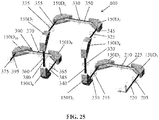
- FIG. 25 is an isometric diagram illustrating a representative sixth electrostatic mirror prism arrangement 400 having representative electrostatic mirror prisms 150D in a second cascaded arrangement or configuration for a representative TOF mass analyzer 100 apparatus embodiment and a representative TOF system 200 embodiment.
- the electrostatic mirror prisms 150 are arranged pair-wise, in groups of two electrostatic mirror prisms 150.
- ten electrostatic mirror prisms 150D 1 through 150D 10 have been cascaded in pairs, i.e., arranged serially, with the output TOF focus of one pair of electrostatic mirror prisms 150D being the input TOF focus of the next pair of electrostatic mirror prisms 150D.
- this second cascaded arrangement or configuration forming representative electrostatic mirror prism arrangement 400 differs from the first cascaded arrangement or configuration 405 (representative electrostatic mirror prism arrangement 300) insofar as the representative electrostatic mirror prism arrangement 400 is non-planar (i.e., not confined to the illustrated x-y plane, also referred to as the "energy dispersion plane"), and extends into a third dimension along the z-axis, as illustrated.
- an ion detector 120 is typically positioned at this last output TOF focus plane 375, and together with the representative electrostatic mirror prism arrangement 400, forms another representative TOF mass analyzer 100 apparatus embodiment.
- the time-of-flight " T " has been increased 5-fold, while the width of the mass spectrum at one-half the maximum " ⁇ T " has changed insignificantly due to multiple TOF focusing events, thus considerably increasing the mass resolving power.
- implementation of bandpass energy filtering as described above, at any or all of the five intermediate focuses (210, 320, 330, 360, 370) for spatially dispersed ions of different energies will further narrow " ⁇ T" and further improve mass resolution.
- This representative electrostatic mirror prism arrangement 400 is three-dimensional, such that four rotations of energy dispersion planes by 90° occur at four intermediate output-input focuses (215, 325, 335, 365) where the pairs of electrostatic mirror prisms 150D are sequentially interfaced (the first pair with the second pair, the second pair with the third pair, the third pair with the fourth pair, and the fourth pair with the fifth pair). It is important to recognize that rotations at these focuses are possible because ions of different energies have been recombined in one single beam for traversing or flying through these intermediate output-input focuses (215, 325, 335, 365).
- the input focus 205 (from a pulsed ion source 105 or intervening components), five intermediate focuses (210, 320, 330, 360, 370) for spatially dispersed ions of different energies, where the bandpass filter 140 energy control slit(s) 255 can be positioned for kinetic energy filtering, four combined output-input focuses (215, 325, 335, 365), and an output TOF focus 375 where the TOF ion detector 120 can be placed.
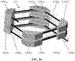
- FIG. 26 is an isometric diagram illustrating a representative seventh electrostatic mirror prism arrangement 415 having representative electrostatic mirror prisms 150D in a third cascaded arrangement or configuration for a representative TOF mass analyzer 100 apparatus embodiment and a representative TOF system 200 embodiment.
- This third cascaded arrangement or configuration forming representative electrostatic mirror prism arrangement 415 differs from the representative electrostatic mirror prism arrangement 400 insofar as the representative electrostatic mirror prism arrangement 415 is more compact.
- This representative electrostatic mirror prism arrangement 415 is a folded three-dimensional equivalent to the representative electrostatic mirror prism arrangement 400, with the main difference that instead of four ninety degree rotations of energy dispersion planes, there are four rotations by 10° only.
- FIGs. 27A, 27B , 27C, and 27D are isometric diagrams illustrating a representative eighth electrostatic mirror prism arrangement 430 having representative electrostatic mirror prisms 150F with additional first and second electrostatic mirrors 150 of the reflectron-type design (referred to as "reflectrons") 420, 425 for a representative TOF mass analyzer 100 apparatus embodiment and a representative TOF system 200 embodiment.
- Electrostatic mirror prisms 150E may also be substituted for the electrostatic mirror prisms 150F and utilized equivalently for this representative electrostatic mirror prism arrangement 430, because both electrostatic mirror prisms 150E and 150F feature the ion-transparent rear electrode design, as shown in FIGs. 19 and 20 .
- the electrostatic mirror prism 150F differs from the other electrostatic mirror prisms insofar as the electrostatic mirror prism 150F has a grid configuration of the third, rear electrode 155F, which also allows for the ion beam (e.g., second or secondary ion beam 225 or third or tertiary ion beam 230) to pass through the electrostatic mirror prism 150F without significant disturbance when the electrostatic mirror prism 150F is off and its electrodes are not electrostatically biased to deflect ions.
- the ion beam e.g., second or secondary ion beam 225 or third or tertiary ion beam 230
- the on and off states of the first electrostatic mirror prism 150F 1 , and the second electrostatic mirror prism 150F 2 may be controlled by the processor 130 and/or more generally by the computing device 132, thereby controlling the generation of electric fields by these devices and, correspondingly, whether any retarding electric fields will be generated.
- the reflectrons 420, 425 no off state is needed, and they can be always on because they are outside of the electrostatic mirror prisms 150F (RAIMPs) and thus do not affect the trajectories of ions when they pass through the electrostatic mirror prisms 150F in its main operating mode.
- Each of the first and second reflectrons 420, 425, as illustrated in FIG. 27 may be implemented as a type of electrostatic mirror prism 150, such as using an electrostatic mirror prism 150 or an electrostatic mirror prism 150A, for example and without limitation.
- the electrostatic mirror prism 150, 150A is configured to have comparatively increased depth, as illustrated, with depth being in the direction or orientation from the front electrode 165, 165A to the rear electrode 155, 155A, and further the central axis 427 (i.e., the center and normal along the depth) of the electrostatic mirror prism 150, 150A is oriented and aligned to be coextensive or co-arranged with the incoming ion beam as illustrated in FIGs.
- the ion beam should have a zero or negligible angle of incidence, as defined above.
- the retarding electric field generated by the electrostatic mirror prism 150, 150A forming the reflectron 420, 425 the incoming ion beam will enter the reflectron 420, 425, and its ions will decelerate to a complete stop, followed by accelerating in the opposite direction (180° from the incoming beam) out of the electrostatic mirror prism 150, 150A, with the output ion beam having about the same kinetic energy dispersion, if any, as the incoming ion beam.
- the representative TOF mass analyzer 100 apparatus embodiment and representative TOF system 200 embodiment having this representative electrostatic mirror prism arrangement 430 have several different modes of operation, a first operating mode utilizing only the first electrostatic mirror prism 150F 1 and the second electrostatic mirror prism 150F 2 , and a second, "shuttle" operating mode using both the first and second reflectrons 420, 425 with both of the first electrostatic mirror prism 150F 1 and the second electrostatic mirror prism 150F 2 in an off state.
- the first electrostatic mirror prism 150F 1 and the second electrostatic mirror prism 150F 2 are turned on and off, generally through a remotely controlled switching system (not separately illustrated), which is under the control of the processor 130.
- the representative electrostatic mirror prism arrangement 430 comprises a pair of two electrostatic mirror prisms 150F having an angular offset of 90 degrees, such as for a representative electrostatic mirror prism arrangement 145 discussed above.
- the first electrostatic mirror prism 150F 1 will receive the first or primary (incoming) ion beam 220 having the first or initial TOF focus 205, and when the first electrostatic mirror prism 150F 1 is on and its electrodes are electrostatically biased to deflect ions (i.e., by generating an electric field), will generate the second or secondary ion beam 225 having the second or secondary TOF focus 210.
- the second or secondary ion beam 225 is provided to the second electrostatic mirror prism 150F 2 , and when the second electrostatic mirror prism 150F 2 is on and its electrodes are electrostatically biased to deflect ions, will generate the third or tertiary ion beam 230 having the third or tertiary TOF focus plane 215, where an ion detector 120 is positioned, as discussed above, and as illustrated in FIG. 27A .
- this operating mode which can also be called a "survey mode"
- the electrostatic mirror prism arrangement 430 can be used for TOF-MS measurements with moderate resolution and with no limit on the detected range of ion masses.
- the additional first and second reflectrons 420, 425 are arranged linearly with respect to the two electrostatic mirror prisms 150F, i.e., in line with the second or secondary ion beam 225, and having the same intermediate TOF focus 210, which for the first and second reflectrons 420, 425, is also a combined output-input focus.
- the first electrostatic mirror prism 150F 1 also will receive the first or primary (incoming) ion beam 220 having the first or initial TOF focus 205, and when the first electrostatic mirror prism 150F 1 is on and its electrodes are electrostatically biased to deflect ions, will generate the second or secondary ion beam 225 having the second or secondary TOF focus 210. This allows the first or primary (incoming) ion beam 220 to be "injected” and used to produce the second or secondary ion beam 225 for this second operating mode. Also for this second operating mode, the second electrostatic mirror prism 150F 2 is turned off at this time.
- the second electrostatic mirror prism 150F 2 when the second electrostatic mirror prism 150F 2 is not generating an electric field (i.e., is not on and its electrodes are not electrostatically biased to deflect ions) and becoming ion-transparent, so that the second or secondary ion beam 225 will pass (substantially undisturbed) through the second electrostatic mirror prism 150F 2 into the second reflectron 425, as illustrated in FIG. 27B .
- these ions are separated in the energy dispersion plane into parallel beams of ions with different energies, as discussed above.
- the second or secondary ion beam 225 is reflected by the second reflectron 425 and passes (substantially undisturbed) through both the second electrostatic mirror prism 150F 2 and the first electrostatic mirror prism 150F 1 to the first reflectron 420, as illustrated in FIG. 27C .
- the second or secondary ion beam 225 is reflected back by the first reflectron 420 and passes (substantially undisturbed) through both the first electrostatic mirror prism 150F 1 and the second electrostatic mirror prism 150F 2 to the second reflectron 425, also as illustrated in FIG. 27C .
- the second or secondary ion beam 225 will continue to be reflected back and forth in a shuttle-type motion between the first and second reflectrons 420, 425, until ejection, as controlled by the processor 130 and/or by the computing device 132, as described below.
- Potentials on the electrodes of the first electrostatic mirror prism 150F 1 are turned off (to ground potential) when the lightest ions of the mass range of interest to be examined with high mass resolving power pass through the second or secondary TOF focus 210 on their way back from the second reflectron 425. These ions then can fly straight through the first electrostatic mirror prism 150F 1 and enter the first reflectron 420 (also orthogonally to its retarding field) to get reflected straight back towards the second or secondary TOF focus 210, as a combined output-input focus. In this case, a process of consecutive and alternating back and forth reflections between the first and second reflectrons 420, 425 (the shuttle movement) can go until the second electrostatic mirror prism 150F 2 is switched on again.
- This switching is done when the lightest ions of the mass range of interest to be examined with high mass resolving power pass through the second or secondary TOF focus 210 on their way back from the first reflectron 420. At each reflection, ions pass through the second or secondary TOF focus 210, where their " ⁇ T " becomes small while " T " (the total time of flight) keeps increasing, potentially providing a mass resolving power in excess of 100,000.
- the time-of-flight "T" can be varied and controlled, based upon user preference or selection, while the width of the mass spectrum at one-half the maximum " ⁇ T " is maintained small (due to multiple TOF focusing events), with the reflections back and forth between the first and second reflectrons 420, 425 continuing until terminated, with the reflected ions "ejected" in the third or tertiary ion beam 230, as illustrated in FIG. 27D , generally as controlled by the processor 130 and/or the computing device 132.
- the second electrostatic mirror prism 150F 2 When the user-selected time-of-flight "T" has elapsed, under the control of the processor 130 and/or the computing device 132, as the second or secondary ion beam 225 is provided to the second electrostatic mirror prism 150F 2 following reflection from the first reflectron 420, instead of passing through the second electrostatic mirror prism 150F 2 , the second electrostatic mirror prism 150F 2 is turned on and its electrodes are electrostatically biased to deflect ions, which will generate the third or tertiary ion beam 230 having the third or tertiary TOF focus plane 215, simultaneously recombining laterally dispersed ion beams with different energies into a single ion beam (i.e., cancelling chromatic aberrations), for detection by the ion detector 120 positioned at the third or tertiary TOF focus plane 215, as discussed above and as illustrated in FIG. 27D .
- the dimensions of the first and second reflectrons 420, 425 and the number of back-and-forth reflections will define, in this representative electrostatic mirror prism arrangement 430, the width of the mass range of interest.
- the input ion package for the first and second reflectrons 420, 425 will be formed by masses located before the first reflection between the first or initial TOF focus 205 (heaviest masses) and the second or secondary TOF focus 210 (lightest masses). This ion package is widening when the number of reflections increases.
- the output ion package will be formed by masses located after the last reflection between the second or secondary TOF focus 210 (lightest masses) and the back plate of the first reflectron 420 (heaviest masses).
- One distinctive feature of the representative electrostatic mirror prism arrangement 430 is that because the electrostatic mirror prisms 150F 1 , 150F 2 and reflectrons 420, 425 share the same TOF focus 210, ions are injected into and ejected from inside the pair of first and second reflectrons 420, 425, via the first electrostatic mirror prism 150F 1 and the second electrostatic mirror prism 150F 2 located in between the first and second reflectrons 420, 425, while in the prior art describing coaxial reflectron pairs with shuttle-type multi-reflection ion movement, the injection of ions is conducted through the back electrode of one of the reflectrons.
- the second or secondary ion beam 225 which is going back and forth between the first and second reflectrons 420, 425 is spatially dispersed into parallel beams of ions with different kinetic energies due to the prismatic properties of the first electrostatic mirror prism 150F 1 .
- This further permits installation of an energy bandpass filter 140 having an energy control slit 255 at the second or secondary TOF focus 210, so that ions with undesired energies can be cut off multiple times in order to suppress "tails" of TOF mass spectral peaks and filter out low energy fragment ions.
- the TOF mass analyzer 110 and system 200 embodiments having the representative electrostatic mirror prism arrangement 430 comprises the energy-isochronous multi-pass TOF MS with band-pass energy filtering, which are novel and nonobvious features.
- first and second reflectrons 420, 425 with elliptical or rectangular front cross-sections may be utilized to better accommodate spatially dispersed sheet-like ion beams, such as the second or secondary ion beam 225, in addition to or alternatively to using coaxial cylindrical reflectrons having large diameters.
- FIGs. 28A, 28B , 28C, and 28D are isometric diagrams illustrating a representative ninth electrostatic mirror prism arrangement 450 having representative electrostatic mirror prisms 150, 150D, and 150F in a fourth cascaded arrangement or configuration for a representative TOF mass analyzer 100 apparatus embodiment and a representative TOF system 200 embodiment, utilizing a first electrostatic mirror prism 150 1 , a second electrostatic mirror prism 150 2 , a third electrostatic mirror prism 150F 3 , a fourth electrostatic mirror prism 150D 4 , a fifth electrostatic mirror prism 150D 5 and a sixth electrostatic mirror prism 150F 6 .
- Electrostatic mirror prisms 150E may also be substituted for the electrostatic mirror prisms 150F and utilized equivalently for this representative electrostatic mirror prism arrangement 450, because both electrostatic mirror prisms 150E and 150F feature the ion-transparent rear electrode design, as shown in FIGs. 19 and 20 , as well as the gridless electrostatic mirror prism embodiments, such as 150C and 150D, if their rear electrode is modified to become ion-transparent by implementing a grid or a solid plate with an opening 315, as previously described.
- the electrostatic mirror prism 150F differs from the electrostatic mirror prism 150 insofar as the electrostatic mirror prism 150F has a gridded configuration (i.e., ion-transparent) of the third, rear electrode 155F, which also allows for the ion beam to pass through the electrostatic mirror prism 150F without significant disturbance when the electrostatic mirror prism 150F is off and its electrodes are not electrostatically biased to deflect ions.
- the on and off states of the electrostatic mirror prisms 150F 3 and 150F 6 also may be controlled by the processor 130 and/or more generally by the computing device 132, thereby controlling the generation of electric fields by these devices and, correspondingly, whether any retarding electric fields will be generated.
- the states of the first electrostatic mirror prism 150 1 , the second electrostatic mirror prism 150 2 , the fourth electrostatic mirror prism 150D 4 , and the fifth electrostatic mirror prism 150D 5 may be always on.
- the representative TOF mass analyzer 100 apparatus embodiment and representative TOF system 200 embodiment having this representative electrostatic mirror prism arrangement 450 have several different modes of operation, a first operating mode utilizing only the first electrostatic mirror prism 150 1 and the second electrostatic mirror prism 150 2 , and a second, "ring" operating mode using all four of the third electrostatic mirror prism 150F 3 , the fourth electrostatic mirror prism 150D 4 , the fifth electrostatic mirror prism 150D 5 and the sixth electrostatic mirror prism 150F 6 , and then also using both of the first electrostatic mirror prism 150 1 and the second electrostatic mirror prism 150 2 for ion ejection.
- electrostatic mirror prisms 150 may be substituted equivalently for these various electrostatic mirror prisms 150 illustrated in FIG. 28 , with the caveat that while they all can be of gridded and gridless designs, the electrostatic mirror prisms 150F require implementation of ion-transparent back electrodes as discussed above.
- the third electrostatic mirror prism 150F 3 and the sixth electrostatic mirror prism 150F 6 are turned on and off, generally through a remotely controlled switching system (not separately illustrated), which is under the control of the processor 130.
- the representative electrostatic mirror prism arrangement 450 comprises: (1) a first pair of two electrostatic mirror prisms 150, the first electrostatic mirror prism 150 1 and the second electrostatic mirror prism 150 2 , having an angular offset of 90 degrees, such as for a representative electrostatic mirror prism arrangement 145 discussed above; (2) a second pair of two electrostatic mirror prisms 150, the third electrostatic mirror prism 150F 3 and the fourth electrostatic mirror prism 150D 4 , also having an angular offset of 90 degrees, such as for a representative electrostatic mirror prism arrangement 145 discussed above; and (3) a third pair of two electrostatic mirror prisms 150, the fifth electrostatic mirror prism 150D 5 and the sixth electrostatic mirror prism 150F 6 , also having an angular offset of 90 degrees, such as for a representative electrostatic mirror prism arrangement 145 discussed above.
- the first electrostatic mirror prism 150 1 and the third electrostatic mirror prism 150F 3 have the same primary input TOF focus 460;
- TOF focus 460 is also a combined output-input TOF focus of the sixth electrostatic mirror prism 150F 6 ;
- the combined output-input TOF focus 480 is interfacing the second and third pairs of electrostatic mirror prisms (the third electrostatic mirror prism 150F 3 and the fourth electrostatic mirror prism 150D 4 interfacing with the fifth electrostatic mirror prism 150D 5 and the sixth electrostatic mirror prism 150F 6 ).
- the third electrostatic mirror prism 150F 3 and the sixth electrostatic mirror prism 150F 6 are off, so that the first electrostatic mirror prism 150 1 will receive the first or primary (incoming) ion beam 510 having the first or initial TOF focus 460, passing through the sixth electrostatic mirror prism 150F 6 and the third electrostatic mirror prism 150F 3 . Since the first electrostatic mirror prism 150 1 is on and its electrodes are electrostatically biased to deflect ions, the first electrostatic mirror prism 150 1 will generate an intermediate ion beam 515 (with spatially-dispersed ions according to their kinetic energies, as previously described) having an intermediate TOF focus 525.
- the intermediate ion beam 515 is provided to the second electrostatic mirror prism 150 2 , and since the second electrostatic mirror prism 150 2 is also on and its electrodes are electrostatically biased to deflect ions, will generate an output ion beam 520 having an output TOF focus plane 530, where an ion detector 120 is to be positioned as discussed above for FIGs. 3 and 4 , and as illustrated in FIG. 28A .
- this operating mode which can also be called a "survey mode”
- the arrangement 450 electrostatic mirror prism arrangement 450 can be used for TOF-MS measurements with moderate resolution and with no limit on detected range of ion masses.
- the fourth electrostatic mirror prism 150D 4 and the fifth electrostatic mirror prism 150D 5 are arranged to form a square or rectangular ring structure with the third electrostatic mirror prism 150F 3 and the sixth electrostatic mirror prism 150F 6 .
- the sixth electrostatic mirror prism 150F 6 also will receive the first or primary (incoming) ion beam 510 having the input TOF focus 460, and when the sixth electrostatic mirror prism 150F 6 is off, the first or primary (incoming) ion beam 510 will pass through the sixth electrostatic mirror prism 150F 6 to the third electrostatic mirror prism 150F 3 .
- the third electrostatic mirror prism 150F 3 is now on and its electrodes are electrostatically biased to deflect ions, so that it will generate a fourth ion beam 465, having spatially-dispersed kinetic energies as described above, and having a fourth (intermediate) TOF focus 470.
- This allows the first or primary (incoming) ion beam 510 to be "injected” and used to produce a series of ion beams for this second operating mode, as illustrated in FIG. 28B .
- the fourth electrostatic mirror prism 150D 4 and fifth electrostatic mirror prism 150D 5 are also on at this time (either turned on for this mode or always on). It should be noted that due to prismatic functionality of the third electrostatic mirror prism 150F 3 , these ions are separated in the energy dispersion plane into parallel beams of ions in the fourth ion beam 465 with different energies, as discussed above.
- the fourth ion beam 465 is provided to the fourth electrostatic mirror prism 150D 4 which generates a fifth, convergent ion beam 475 having a fifth, output TOF focus 480, which is also the input TOF focus for the fifth electrostatic mirror prism 150D 5 , which generates a sixth ion beam 485, having spatially-dispersed kinetic energies as described above, and having a sixth (intermediate) TOF focus 490, which is also the input TOF focus for sixth electrostatic mirror prism 150F 6 , as illustrated in FIG. 28B .
- the sixth electrostatic mirror prism 150F 6 now being turned on with its electrodes electrostatically biased to deflect ions, the sixth ion beam 485 is reflected by the sixth electrostatic mirror prism 150F 6 and generates a seventh, convergent ion beam 455 having the combined output-input TOF focus 460, which is also the input TOF focus to the third electrostatic mirror prism 150F 3 (and also to the first electrostatic mirror prism 150 1 ), as illustrated in FIG. 28C .
- the ion beams 455, 465, 475, and 485 will continue to be generated along this square or rectangular ring of electrostatic mirror prisms 150, as controlled by the processor 130 and/or by the computing device 132.
- potentials on the electrodes of the third electrostatic mirror prism 150F 3 are turned on no later than when the lightest ions of the mass range of interest to be examined pass through the input TOF focus 460, and potentials on the electrodes of the sixth electrostatic mirror prism 150F 6 are turned on no later than when the lightest ions of the mass range of interest to be examined with high mass resolving power first pass through the sixth (intermediate) TOF focus 490.
- a process of consecutive reflections around the square or rectangular ring of electrostatic mirror prisms 150 can go until the third electrostatic mirror prism 150F 3 is switched off again, to pass the ions to the pair of electrostatic mirror prisms 150 1 and 150 2 , which transfers them from input TOF focus 460 to the output TOF focus 530.
- This switching is done when the lightest ions of the mass range of interest to be examined with high mass resolving power pass through the input TOF focus 460.
- ions pass through the TOF focuses 460, 470, 480, and 490, where their " ⁇ T " becomes small while " T " (the total time of flight) keeps increasing, also potentially providing a mass resolving power in excess of 100,000.
- the time-of-flight " T " can be varied and controlled, based upon user preference or selection, with the reflections continuing around the square or rectangular ring of the third electrostatic mirror prism 150F 3 , the fourth electrostatic mirror prism 150D 4 , the fifth electrostatic mirror prism 150D 5 , and the sixth electrostatic mirror prism 150F 6 , until terminated.
- the user-selected time-of-flight " T " has elapsed, under the control of the processor 130 and/or the computing device 132, the reflected ions are then "ejected" when the third electrostatic mirror prism 150F 3 is turned off.
- both the first electrostatic mirror prism 150 1 and the second electrostatic mirror prism 1502 have been kept on (or are turned on), with the convergent ion beam 455 passing through the third electrostatic mirror prism 150F 3 , reflected by the first electrostatic mirror prism 150 1 to form the intermediate ion beam 515, which in turn is reflected by the second electrostatic mirror prism 150 2 to provide the output ion beam 520, again recombining laterally dispersed ion beams with different energies into a single ion beam (i.e., cancelling chromatic aberrations), for detection by the ion detector 120 positioned at the output TOF focus plane 530, as discussed above and as illustrated in FIG. 28D .
- the moment the third electrostatic mirror prism 150F 3 is switched off determines the range of masses that can be detected.
- This representative electrostatic mirror prism arrangement 450 for a representative TOF mass analyzer 100, 100A apparatus embodiment and a representative TOF system 200, 200A apparatus embodiment provides another example of an energy-isochronous multi-pass TOF MS with band-pass energy filtering based on electrostatic mirror prisms 150 only.
- the electrostatic mirror prism arrangement 450 has an important scaling feature, namely, increasing lateral dimensions of the electrostatic mirror prisms 150 leads to a prolongation of the ion flight path between the input and output TOF focuses 460, 530, respectively.
- the first electrostatic mirror prism 150 1 and the second electrostatic mirror prism 150 2 are comparatively larger than the other four electrostatic mirror prisms (the third electrostatic mirror prism 150F 3 , the fourth electrostatic mirror prism 150D 4 , the fifth electrostatic mirror prism 150D 5 , and the sixth electrostatic mirror prism 150F 6 ), also achieving higher mass resolving power for single ion pass operation.
- the electrode potentials are always on for the first electrostatic mirror prism 150 1 and the second electrostatic mirror prism 150 2 , allowing measurements of the whole TOF mass spectrum with moderate mass resolving power.
- four comparatively smaller electrostatic mirrors are positioned to form another TOF MS system section with square or rectangular geometry such that:
- the mass range which can be measured using this representative TOF mass analyzer 100 apparatus embodiment and representative TOF system 200 embodiment having this representative electrostatic mirror prism arrangement 450 will depend on the number of turns through the second pair (the third electrostatic mirror prism 150F 3 and the fourth electrostatic mirror prism 150D 4 ) and the third pair (the fifth electrostatic mirror prism 150D 5 and the sixth electrostatic mirror prism 150F 6 ).
- the input ion package for multi-turn analysis will be formed by masses located before the first turn between the input TOF focus 460 for the second pair (the third electrostatic mirror prism 150F 3 and the fourth electrostatic mirror prism 150D 4 ) (heaviest masses) and the intermediate TOF focus 490 of the third pair (the fifth electrostatic mirror prism 150D 5 and the sixth electrostatic mirror prism 150F 6 ) (lightest masses).
- the output ion package for multi-turn TOF-MS analysis will be formed by masses located after the last turn between the input TOF focus 460 (lightest masses) and the intermediate TOF focus 470 (heaviest masses) of the second pair (the third electrostatic mirror prism 150F 3 and the fourth electrostatic mirror prism 150D 4 ).
- FIG. 29 is an isometric diagram illustrating a tenth representative electrostatic mirror prism arrangement 500 having a plurality of representative electrostatic mirror prisms 150D having a fifth cascaded and tandem arrangement or configuration, for a representative TOF mass analyzer 100 apparatus embodiment and a representative TOF system 200 embodiment, and is a variation of the representative fifth electrostatic mirror prism arrangement 300 discussed above.
- electrostatic mirror prisms 150 For the tenth representative electrostatic mirror prism arrangement 500, four electrostatic mirror prisms 150 are utilized, with electrostatic mirror prisms 150D illustrated for example and without limitation, in conjunction with a dissociation device 505, such as a laser beam generator (i.e., a laser) or an electron beam generator, for example and without limitation, to cause photo-dissociation or electron impact dissociation of selected masses of interest.
- a dissociation device 505 such as a laser beam generator (i.e., a laser) or an electron beam generator, for example and without limitation, to cause photo-dissociation or electron impact dissociation of selected masses of interest.
- the electrostatic mirror prisms 150 are arranged pair-wise, in groups of two electrostatic mirror prisms 150. As illustrated in FIG. 29 , four electrostatic mirror prisms 150D have been cascaded, i . e ., arranged serially, with a first electrostatic mirror prism 150D 1 paired with a second electrostatic mirror prism 150D 2 as a first pair, and with a third electrostatic mirror prism 150D 3 paired with a fourth electrostatic mirror prism 150D 4 as a second pair.
- the output TOF focus of one pair of electrostatic mirror prisms 150 becomes the input TOF focus of the next pair of electrostatic mirror prisms 150. As illustrated, there are five TOF focuses 205, 210, 215, 320, and 325, and five ion beams 220, 225, 230, 340, and 345.
- This tenth representative electrostatic mirror prism arrangement 500 is also an example of multi-reflection (cascade) electrostatic mirror prism 150 TOF-MS design using two pairs of gridless electrostatic mirror prisms 150D, although any type of electrostatic mirror prisms 150 discussed above (gridded or gridless) may be utilized equivalently.
- the two pairs of electrostatic mirror prisms 150 lie in the same "energy dispersion plane", and there are five TOF focuses as mentioned above: the input focus 205 (from a pulsed ion source 105 or intervening components), two "intermediate” focuses for spatially dispersed ions of different energies (210, 320), one combined output-input focus (215) to interface between the first and second pairs or sets of electrostatic mirror prisms 150, and the last output focus 325 where an ion detector 120 can be placed.
- a first or primary ion beam 220 (having a first or initial TOF focus 205) is input into the first electrostatic mirror prism 150D 1 , which generates a second or secondary ion beam 225 (having spatially-dispersed ions according to their kinetic energies and having a second or secondary (intermediate) TOF focus 210) to the second electrostatic mirror prism 150D 2 , which generates a converged or recombined third or tertiary ion beam 230 (having a third or tertiary TOF focus 215, as a combined output-input focus).
- the third or tertiary ion beam 230 is input into the third electrostatic mirror prism 150D 3 , which generates a next intermediate ion beam 340 (having spatially-dispersed ions according to their kinetic energies and having an intermediate TOF focus 320) provided to the fourth electrostatic mirror prism 150D 4 , which generates another, converged or recombined output ion beam 345 (having an output TOF focus 325).
- an ion detector 120 is typically positioned at this output TOF focus plane 325, and together with the representative electrostatic mirror prism arrangement 500, forms another representative TOF mass analyzer 100 apparatus embodiment.
- any bandpass energy filtering may be implemented as described above, at any of the two intermediate focuses 210 and 320, for spatially dispersed ions of different energies, and is illustrated using first and second bandpass filters 140A and 140B, respectively.
- the multi-"ricochet" representative electrostatic mirror prism arrangement 500 has the capability of operating in MS-MS mode, also referred to as a tandem mode.
- the first energy bandpass filter 140A having an energy bandpass control slit 255 should be positioned or arranged at the first intermediate TOF focus 210, and a second bandpass filter 140B at the next intermediate TOF focus 320.
- the energy bandpass filter 140A at intermediate TOF focus 210 assures that no fragment ions penetrate beyond its location.
- ions with different m / z may be well confined in space but spread over time.
- a group of MS peaks corresponding to a molecular ion which may be identified (referred to herein as a "precursor"), can be intercepted at a chosen moment either by a well-focused pulsed laser beam or by an electron beam generated by the dissociation device 505 in order to trigger intense molecular fragmentation (either via photo-dissociation or electron impact dissociation) and produce fragment ions.
- the kinetic energies these fragment ions may be lower than those of the precursor, being a fraction of its energy proportional to the ratio between the fragment and precursor masses.
- the dispersed in space fragment ions may pass through the fourth electrostatic mirror prism 150D 4 and reach an ion detector 120 (positioned at the output TOF focus 325) with unique flight times. In the mass spectrum, this may be seen as either a disappearance or an attenuation of the precursor peak and appearance of new peaks at different times. If the energy bandpass filter 140B is installed at TOF focus 320, it may be aligned, if needed, such that only the fragment ions are passing through the mirror prism 150D 4 and reaching ion detector 120.
- fractions of kinetic energy divided between the fragments can be calculated based on the knowledge of the geometry of the representative electrostatic mirror prism arrangement 500. Having the energy bandpass filter 140B implemented at TOF focus 320 may help better calibrate MS-MS operation and improve fragment identification. This will permit unambiguous identification of the precursor ion and its fragmentation channels.
- this MS-MS operation mode can be run as one half of the TOF-MS duty cycle so that fragment ions may be formed just for one out of two ion pulses, and each half may be acquired with a separate time-to-digital converter or digitizer. In this case, MS-MS analysis may be conducted in real time and quasi-simultaneously with regular TOF-MS analysis.
- Time-of-flight mass spectrometry in an MS-MS mode may be performed using two sets of the representative electrostatic mirror prism arrangement 500 operating in parallel, each with an incoming ion beam 220 generated from the pulsed ion source 105, but with fragmentation occurring in only one of the two parallel representative electrostatic mirror prism arrangements 500.
- the knowledge of the representative electrostatic mirror prism arrangement 500 geometry and the nominal kinetic energy of ions permits the determination of the kinetic energy of detected fragment ions from their time of flight.
- the knowledge of the kinetic energy of detected fragment ions permits the determination of fragmentation channels and thus identification of the molecular precursor ion.
- Performing the TOF-MS detection with two time-to-digital converters or digitizers triggered in alternating fashion (such that the pulsed laser or electron beam are fired at only one out of two triggering pulses, and the pulsed ion source is triggered at every pulse) enables quasi-parallel measurements of fragment-free and fragment-containing TOF-MS spectra that can be directly compared to assure that precursor and fragment ions come from the same analytical volume.
- a TOF-MS apparatus 100, 100A and system 200, 200A using a plurality of representative electrostatic mirror prism arrangement, which can select and/or control the kinetic energies of the ions comprising the ion beam, to create an ion beam having a selectable and comparatively narrow band of kinetic energies.
- Such embodiments of a TOF-MS apparatus 100, 100A and system 200, 200A also provide for selectable or configurable time-of-flight in various system embodiments, and may include multiple TOF focuses and tandem operation.
- Such embodiments of a TOF-MS apparatus 100, 100A and system 200, 200A also selectively preserve spatial information in detection, to allow for stigmatic imaging.
- such embodiments of a TOF-MS apparatus 100, 100A and system 200, 200A are capable of multimode operation, to selectively operate or configure the embodiments of a TOF-MS apparatus 100, 100A and system 200, 200A for these various features and in various combinations.
- the pulsed ion source 105 may optionally include any ion optics, ion guides or ion accelerators, and provides a first or primary ion beam 220 to the TOF mass analyzer 100, 100A.
- the ion optics are typically arranged in an evacuated volume (e.g., substantially devoid of neutral gas-phase molecules to be essentially collision-free) of a desired axial length between the ion guide(s) 110 and the entrance to the TOF mass analyzer 100, 100A.
- the ion optics may be, as examples, a cylindrical electrode coaxial with the axis, a plate with an aperture on-axis, or pair of plates or half-cylinders separated by a gap on-axis.
- DC potentials may be applied to one or more of the ion lenses.
- One or more of the ion lenses may be configured as an ion slicer that ensures that the geometry of the ion beam matches the acceptance area of the entrance to the TOF mass analyzer 100, 100A. If a continuous ion beam is generated, such ion optics will also be capable of transforming the continuous ion beam into a pulsed (or packet-based) ion beam 220.
- One or more optional ion guides may be utilized, generally to interface a variety of continuous beam ion sources, sometimes at elevated pressures, with the ion optics operated in a vacuum, and may include an arrangement of electrodes configured for confining ions along an axis while enabling the ions to be transmitted along the axis.
- radio frequency (RF) and/or direct current (DC) voltages may be applied to the ion guide electrodes.
- An ion guide may have a converging geometry, for example, that compresses the ion beam so as to improve transmission into the next device.
- an ion guide may be configured as a multipole structure with electrodes elongated generally along the direction of ion travel; or alternatively may be configured as a straight cylindrical stacked-ring structure or an ion funnel, with ring-shaped electrodes or aperture-containing plate electrodes oriented orthogonal to the direction of ion travel; or may have a planar geometry, for example and without limitation.
- a “processor” may be any type of processor or controller, and may be embodied as one or more processor(s) 130 configured, designed, programmed or otherwise adapted to perform the functionality discussed herein.
- a processor 130 may include use of a single integrated circuit ("IC"), or may include use of a plurality of integrated circuits or other components connected, arranged or grouped together, such as controllers, microprocessors, digital signal processors ("DSPs”), array processors, graphics or image processors, parallel processors, multiple core processors, custom ICs, application specific integrated circuits ("ASICs”), field programmable gate arrays (“FPGAs”), adaptive computing ICs, associated memory (such as RAM, DRAM and ROM), and other ICs and components, whether analog or digital.
- DSPs digital signal processors
- ASICs application specific integrated circuits
- FPGAs field programmable gate arrays
- adaptive computing ICs associated memory (such as RAM, DRAM and ROM), and other ICs and components, whether analog or
- processor or controller should be understood to equivalently mean and include a single IC, or arrangement of custom ICs, ASICs, processors, microprocessors, controllers, FPGAs, adaptive computing ICs, or some other grouping of integrated circuits which perform the functions discussed herein, with associated memory, such as microprocessor memory or additional RAM, DRAM, SDRAM, SRAM, MRAM, ROM, FLASH, EPROM or E 2 PROM.
- a processor 130, with associated memory may be adapted or configured (via programming, FPGA interconnection, or hard-wiring) to perform the methodology of the invention, as discussed herein, such as to control the various embodiments of a TOF-MS apparatus 100, 100A and system 200, 200A.
- the methodology may be programmed and stored, in a processor 130 with its associated memory (and/or memory 125) and other equivalent components, as a set of program instructions or other code (or equivalent configuration or other program) for subsequent execution when the processor 130 is operative (i.e., powered on and functioning).
- the processor 130 may implemented in whole or part as FPGAs, custom ICs and/or ASICs, the FPGAs, custom ICs or ASICs also may be designed, configured and/or hard-wired to implement the methodology of the invention.
- the processor 130 may be implemented as an arrangement of analog and/or digital circuits, controllers, microprocessors, DSPs and/or ASICs, collectively referred to as a "processor” or “controller”, which are respectively hard-wired, programmed, designed, adapted or configured to implement the methodology of the invention, including possibly in conjunction with a memory 125.
- the memory 125 which may include a data repository (or database), may be embodied in any number of forms, including within any computer or other machine-readable data storage medium, memory device or other storage or communication device for storage or communication of information, currently known or which becomes available in the future, including, but not limited to, a memory integrated circuit ("IC"), or memory portion of an integrated circuit (such as the resident memory within a processor 130 or processor IC), whether volatile or non-volatile, whether removable or non-removable, including without limitation RAM, FLASH, DRAM, SDRAM, SRAM, MRAM, FeRAM, ROM, EPROM or E 2 PROM, or any other form of memory device, such as a magnetic hard drive, an optical drive, a magnetic disk or tape drive, a hard disk drive, other machine-readable storage or memory media such as a floppy disk, a CDROM, a CD-RW, digital versatile disk (DVD) or other optical memory, or any other type of memory, storage medium, or data storage apparatus or circuit, which is known or which becomes known
- the processor 130 is hard-wired or programmed, using software and data structures of the invention, for example, to perform the methodology of the present invention.
- the system and related methods of the present invention may be embodied as software which provides such programming or other instructions, such as a set of instructions and/or metadata embodied within a non-transitory computer readable medium, discussed above.
- metadata may also be utilized to define the various data structures of a look up table or a database.
- Such software may be in the form of source or object code, by way of example and without limitation. Source code further may be compiled into some form of instructions or object code (including assembly language instructions or configuration information).
- the software, source code or metadata of the present invention may be embodied as any type of code, such as C, C++, Matlab, SystemC, LISA, XML, Java, Brew, SQL and its variations (e.g., SQL 99 or proprietary versions of SQL), DB2, Oracle, or any other type of programming language which performs the functionality discussed herein, including various hardware definition or hardware modeling languages (e.g., Verilog, VHDL, RTL) and resulting database files (e.g., GDSII).
- various hardware definition or hardware modeling languages e.g., Verilog, VHDL, RTL
- resulting database files e.g., GDSII
- a "construct”, “program construct”, “software construct” or “software”, as used equivalently herein, means and refers to any programming language, of any kind, with any syntax or signatures, which provides or can be interpreted to provide the associated functionality or methodology specified (when instantiated or loaded into a processor or computer and executed, including the processor 130, for example).
- the software, metadata, or other source code of the present invention and any resulting bit file may be embodied within any tangible, non-transitory storage medium, such as any of the computer or other machine-readable data storage media, as computer-readable instructions, data structures, program modules or other data, such as discussed above with respect to the memory 125, e.g. , a floppy disk, a CDROM, a CD-RW, a DVD, a magnetic hard drive, an optical drive, or any other type of data storage apparatus or medium, as mentioned above.
- any tangible, non-transitory storage medium such as any of the computer or other machine-readable data storage media, as computer-readable instructions, data structures, program modules or other data, such as discussed above with respect to the memory 125, e.g. , a floppy disk, a CDROM, a CD-RW, a DVD, a magnetic hard drive, an optical drive, or any other type of data storage apparatus or medium, as mentioned above.
- the network interface 135 is utilized for appropriate connection to a relevant channel, network or bus; for example, the network interface 135 may provide impedance matching, drivers and other functions for a wireline interface, may provide demodulation and analog to digital conversion for a wireless interface, and may provide a physical interface, respectively, for the computing device 132 and/or for the processor 130 and/or memory 125, with other devices.
- the network interface 135 is used to receive and transmit data, depending upon the selected embodiment, such as program instructions, parameters, configuration information, control messages, data and other pertinent information.
- the network interface 135 may be implemented as known or may become known in the art, to provide data communication between the processor 130 and any type of network or external device, such as wireless, optical, or wireline, and using any applicable standard (e.g., one of the various PCI, USB, RJ 45, Ethernet (Fast Ethernet, Gigabit Ethernet, 300ase-TX, 300ase-FX, etc.), IEEE 802.11, WCDMA, WiFi, GSM, GPRS, EDGE, 3G and the other standards and systems mentioned above, for example and without limitation), and may include impedance matching capability, voltage translation for a low voltage processor to interface with a higher voltage control bus, wireline or wireless transceivers, and various switching mechanisms (e.g., transistors) to turn various lines or connectors on or off in response to signaling from processor 130.
- any applicable standard e.g., one of the various PCI, USB, RJ 45, Ethernet (Fast Ethernet, Gigabit Ethernet, 300ase-TX,
- the network interface 135 may also be configured and/or adapted to receive and/or transmit signals externally to the computing device 132 and/or system 200, respectively, such as through hard-wiring or RF or infrared signaling, for example, to receive information in real-time for output on a display, for example.
- the network interface 135 may provide connection to any type of bus or network structure or medium, using any selected architecture.
- such architectures include Industry Standard Architecture (ISA) bus, Enhanced ISA (EISA) bus, Micro Channel Architecture (MCA) bus, Peripheral Component Interconnect (PCI) bus, SAN bus, or any other communication or signaling medium, such as Ethernet, ISDN, T1, satellite, wireless, and so on.
- each intervening number there between with the same degree of precision is explicitly contemplated.
- the numbers 7 and 8 are contemplated in addition to 6 and 9, and for the range 6.0-7.0, the number 6.0, 6.1, 6.2, 6.3, 6.4, 6.5, 6.6, 6.7, 6.8, 6.9, and 7.0 are explicitly contemplated.
- every intervening sub-range within range is contemplated, in any combination, and is within the scope of the disclosure.
- the sub-ranges 5 - 6, 5 - 7, 5 - 8, 5 - 9, 6 - 7, 6 - 8, 6 - 9, 6 - 10, 7 - 8, 7 - 9, 7 - 10, 8 - 9, 8 - 10, and 9 - 10 are contemplated and within the scope of the disclosed range.
- Coupled means and includes any direct or indirect electrical, structural or magnetic coupling, connection or attachment, or adaptation or capability for such a direct or indirect electrical, structural or magnetic coupling, connection or attachment, including integrally formed components and components which are coupled via or through another component.
Landscapes
- Chemical & Material Sciences (AREA)
- Analytical Chemistry (AREA)
- Physics & Mathematics (AREA)
- Engineering & Computer Science (AREA)
- Plasma & Fusion (AREA)
- Other Investigation Or Analysis Of Materials By Electrical Means (AREA)
- Electron Tubes For Measurement (AREA)
Applications Claiming Priority (2)
| Application Number | Priority Date | Filing Date | Title |
|---|---|---|---|
| US201562260987P | 2015-11-30 | 2015-11-30 | |
| PCT/US2016/064113 WO2017095863A1 (en) | 2015-11-30 | 2016-11-30 | Multimode ion mirror prism and energy filtering apparatus and system for time-of-flight mass spectrometry |
Publications (3)
| Publication Number | Publication Date |
|---|---|
| EP3384520A1 EP3384520A1 (en) | 2018-10-10 |
| EP3384520A4 EP3384520A4 (en) | 2019-06-26 |
| EP3384520B1 true EP3384520B1 (en) | 2022-08-03 |
Family
ID=58798074
Family Applications (1)
| Application Number | Title | Priority Date | Filing Date |
|---|---|---|---|
| EP16871386.5A Not-in-force EP3384520B1 (en) | 2015-11-30 | 2016-11-30 | Multimode ion mirror prism and energy filtering apparatus and system for time-of-flight mass spectrometry |
Country Status (5)
| Country | Link |
|---|---|
| US (1) | US10622203B2 (enExample) |
| EP (1) | EP3384520B1 (enExample) |
| JP (1) | JP6907226B2 (enExample) |
| CA (1) | CA3003060A1 (enExample) |
| WO (1) | WO2017095863A1 (enExample) |
Families Citing this family (21)
| Publication number | Priority date | Publication date | Assignee | Title |
|---|---|---|---|---|
| GB201613988D0 (en) | 2016-08-16 | 2016-09-28 | Micromass Uk Ltd And Leco Corp | Mass analyser having extended flight path |
| GB2567794B (en) | 2017-05-05 | 2023-03-08 | Micromass Ltd | Multi-reflecting time-of-flight mass spectrometers |
| GB2563571B (en) | 2017-05-26 | 2023-05-24 | Micromass Ltd | Time of flight mass analyser with spatial focussing |
| EP3662503A1 (en) | 2017-08-06 | 2020-06-10 | Micromass UK Limited | Ion injection into multi-pass mass spectrometers |
| WO2019030477A1 (en) | 2017-08-06 | 2019-02-14 | Anatoly Verenchikov | ACCELERATOR FOR MASS SPECTROMETERS WITH MULTIPASSES |
| US11211238B2 (en) | 2017-08-06 | 2021-12-28 | Micromass Uk Limited | Multi-pass mass spectrometer |
| US11239067B2 (en) | 2017-08-06 | 2022-02-01 | Micromass Uk Limited | Ion mirror for multi-reflecting mass spectrometers |
| WO2019030471A1 (en) | 2017-08-06 | 2019-02-14 | Anatoly Verenchikov | ION GUIDE INSIDE PULSED CONVERTERS |
| EP3662502A1 (en) | 2017-08-06 | 2020-06-10 | Micromass UK Limited | Printed circuit ion mirror with compensation |
| WO2019030473A1 (en) | 2017-08-06 | 2019-02-14 | Anatoly Verenchikov | FIELDS FOR SMART REFLECTIVE TOF SM |
| GB201802917D0 (en) | 2018-02-22 | 2018-04-11 | Micromass Ltd | Charge detection mass spectrometry |
| GB201806507D0 (en) | 2018-04-20 | 2018-06-06 | Verenchikov Anatoly | Gridless ion mirrors with smooth fields |
| GB201807626D0 (en) | 2018-05-10 | 2018-06-27 | Micromass Ltd | Multi-reflecting time of flight mass analyser |
| GB201807605D0 (en) | 2018-05-10 | 2018-06-27 | Micromass Ltd | Multi-reflecting time of flight mass analyser |
| GB201808530D0 (en) | 2018-05-24 | 2018-07-11 | Verenchikov Anatoly | TOF MS detection system with improved dynamic range |
| GB201810573D0 (en) | 2018-06-28 | 2018-08-15 | Verenchikov Anatoly | Multi-pass mass spectrometer with improved duty cycle |
| GB201901411D0 (en) | 2019-02-01 | 2019-03-20 | Micromass Ltd | Electrode assembly for mass spectrometer |
| GB201903779D0 (en) | 2019-03-20 | 2019-05-01 | Micromass Ltd | Multiplexed time of flight mass spectrometer |
| WO2021207494A1 (en) | 2020-04-09 | 2021-10-14 | Waters Technologies Corporation | Ion detector |
| CN113921373B (zh) * | 2021-09-23 | 2024-10-25 | 中国科学院国家空间科学中心 | 一种多镜面反射飞行时间探测装置 |
| CN118402037A (zh) | 2021-12-15 | 2024-07-26 | 水技术公司 | 具有集成放大器的感应式检测器 |
Family Cites Families (12)
| Publication number | Priority date | Publication date | Assignee | Title |
|---|---|---|---|---|
| EP1405055A4 (en) * | 2001-05-25 | 2007-05-23 | Analytica Of Branford Inc | MULTIPLE DETECTTON SYSTEM |
| US7385187B2 (en) * | 2003-06-21 | 2008-06-10 | Leco Corporation | Multi-reflecting time-of-flight mass spectrometer and method of use |
| US7351958B2 (en) * | 2005-01-24 | 2008-04-01 | Applera Corporation | Ion optics systems |
| GB2455977A (en) * | 2007-12-21 | 2009-07-01 | Thermo Fisher Scient | Multi-reflectron time-of-flight mass spectrometer |
| GB2462065B (en) * | 2008-07-17 | 2013-03-27 | Kratos Analytical Ltd | TOF mass spectrometer for stigmatic imaging and associated method |
| US7919748B2 (en) * | 2009-03-31 | 2011-04-05 | Agilent Technologies, Inc. | Cylindrical geometry time-of-flight mass spectrometer |
| US20110049383A1 (en) * | 2009-09-03 | 2011-03-03 | Advanced Ion Beam Technology, Inc. | Ion implanter and ion implant method thereof |
| GB2476964A (en) * | 2010-01-15 | 2011-07-20 | Anatoly Verenchikov | Electrostatic trap mass spectrometer |
| US8389929B2 (en) * | 2010-03-02 | 2013-03-05 | Thermo Finnigan Llc | Quadrupole mass spectrometer with enhanced sensitivity and mass resolving power |
| US8642951B2 (en) * | 2011-05-04 | 2014-02-04 | Agilent Technologies, Inc. | Device, system, and method for reflecting ions |
| GB201111560D0 (en) * | 2011-07-06 | 2011-08-24 | Micromass Ltd | Photo-dissociation of proteins and peptides in a mass spectrometer |
| GB201118279D0 (en) * | 2011-10-21 | 2011-12-07 | Shimadzu Corp | Mass analyser, mass spectrometer and associated methods |
-
2016
- 2016-11-30 JP JP2018547862A patent/JP6907226B2/ja not_active Expired - Fee Related
- 2016-11-30 EP EP16871386.5A patent/EP3384520B1/en not_active Not-in-force
- 2016-11-30 WO PCT/US2016/064113 patent/WO2017095863A1/en not_active Ceased
- 2016-11-30 CA CA3003060A patent/CA3003060A1/en active Pending
- 2016-11-30 US US15/768,965 patent/US10622203B2/en not_active Expired - Fee Related
Also Published As
| Publication number | Publication date |
|---|---|
| WO2017095863A1 (en) | 2017-06-08 |
| JP6907226B2 (ja) | 2021-07-21 |
| EP3384520A4 (en) | 2019-06-26 |
| EP3384520A1 (en) | 2018-10-10 |
| JP2019505082A (ja) | 2019-02-21 |
| US20180323053A1 (en) | 2018-11-08 |
| US10622203B2 (en) | 2020-04-14 |
| CA3003060A1 (en) | 2017-06-08 |
Similar Documents
| Publication | Publication Date | Title |
|---|---|---|
| EP3384520B1 (en) | Multimode ion mirror prism and energy filtering apparatus and system for time-of-flight mass spectrometry | |
| EP2002461B1 (en) | Mass spectrometer | |
| US8604423B2 (en) | Method for enhancement of mass resolution over a limited mass range for time-of-flight spectrometry | |
| JP6152113B2 (ja) | 加速器デバイスを備える質量分析計及び質量分析方法 | |
| JP5900770B2 (ja) | 直交加速同軸円筒飛行時間型質量分析器 | |
| US8637816B1 (en) | Systems and methods for MS-MS-analysis | |
| GB2477007A (en) | Electrostatic trap mass spectrometer | |
| CN101584021A (zh) | 同轴飞行时间质谱仪 | |
| JP6292319B2 (ja) | 飛行時間型質量分析装置 | |
| US8263932B2 (en) | Mass-analyzing method | |
| US9997345B2 (en) | Orthogonal acceleration coaxial cylinder mass analyser | |
| GB2505275A (en) | Orthogonal acceleration coaxial cylinder time of flight mass analyser | |
| WO2004021386A2 (en) | Mass spectrometer | |
| Santacruz et al. | A constant-momentum/energy-selector time-of-flight mass spectrometer | |
| Lubinsky et al. | 3-D Printed, Compact, Time-of-Flight Reflectron Mass Filters | |
| AU2011237721A1 (en) | Method for enhancement of mass resolution over a limited mass range for time-of-flight spectrometry |
Legal Events
| Date | Code | Title | Description |
|---|---|---|---|
| STAA | Information on the status of an ep patent application or granted ep patent |
Free format text: STATUS: THE INTERNATIONAL PUBLICATION HAS BEEN MADE |
|
| PUAI | Public reference made under article 153(3) epc to a published international application that has entered the european phase |
Free format text: ORIGINAL CODE: 0009012 |
|
| STAA | Information on the status of an ep patent application or granted ep patent |
Free format text: STATUS: REQUEST FOR EXAMINATION WAS MADE |
|
| 17P | Request for examination filed |
Effective date: 20180427 |
|
| AK | Designated contracting states |
Kind code of ref document: A1 Designated state(s): AL AT BE BG CH CY CZ DE DK EE ES FI FR GB GR HR HU IE IS IT LI LT LU LV MC MK MT NL NO PL PT RO RS SE SI SK SM TR |
|
| AX | Request for extension of the european patent |
Extension state: BA ME |
|
| RIN1 | Information on inventor provided before grant (corrected) |
Inventor name: VERYOVKIN, IGOR VLADIMIROVICH Inventor name: HANLEY, LUKE |
|
| DAV | Request for validation of the european patent (deleted) | ||
| DAX | Request for extension of the european patent (deleted) | ||
| REG | Reference to a national code |
Ref country code: DE Ref legal event code: R079 Ref document number: 602016074047 Country of ref document: DE Free format text: PREVIOUS MAIN CLASS: H01J0049060000 Ipc: H01J0049400000 |
|
| A4 | Supplementary search report drawn up and despatched |
Effective date: 20190523 |
|
| RIC1 | Information provided on ipc code assigned before grant |
Ipc: H01J 49/40 20060101AFI20190517BHEP Ipc: H01J 49/48 20060101ALI20190517BHEP |
|
| GRAP | Despatch of communication of intention to grant a patent |
Free format text: ORIGINAL CODE: EPIDOSNIGR1 |
|
| STAA | Information on the status of an ep patent application or granted ep patent |
Free format text: STATUS: GRANT OF PATENT IS INTENDED |
|
| INTG | Intention to grant announced |
Effective date: 20220404 |
|
| GRAS | Grant fee paid |
Free format text: ORIGINAL CODE: EPIDOSNIGR3 |
|
| GRAA | (expected) grant |
Free format text: ORIGINAL CODE: 0009210 |
|
| STAA | Information on the status of an ep patent application or granted ep patent |
Free format text: STATUS: THE PATENT HAS BEEN GRANTED |
|
| AK | Designated contracting states |
Kind code of ref document: B1 Designated state(s): AL AT BE BG CH CY CZ DE DK EE ES FI FR GB GR HR HU IE IS IT LI LT LU LV MC MK MT NL NO PL PT RO RS SE SI SK SM TR |
|
| REG | Reference to a national code |
Ref country code: AT Ref legal event code: REF Ref document number: 1509428 Country of ref document: AT Kind code of ref document: T Effective date: 20220815 Ref country code: CH Ref legal event code: EP |
|
| REG | Reference to a national code |
Ref country code: DE Ref legal event code: R096 Ref document number: 602016074047 Country of ref document: DE |
|
| REG | Reference to a national code |
Ref country code: IE Ref legal event code: FG4D |
|
| REG | Reference to a national code |
Ref country code: LT Ref legal event code: MG9D |
|
| PG25 | Lapsed in a contracting state [announced via postgrant information from national office to epo] |
Ref country code: SE Free format text: LAPSE BECAUSE OF FAILURE TO SUBMIT A TRANSLATION OF THE DESCRIPTION OR TO PAY THE FEE WITHIN THE PRESCRIBED TIME-LIMIT Effective date: 20220803 Ref country code: RS Free format text: LAPSE BECAUSE OF FAILURE TO SUBMIT A TRANSLATION OF THE DESCRIPTION OR TO PAY THE FEE WITHIN THE PRESCRIBED TIME-LIMIT Effective date: 20220803 Ref country code: PT Free format text: LAPSE BECAUSE OF FAILURE TO SUBMIT A TRANSLATION OF THE DESCRIPTION OR TO PAY THE FEE WITHIN THE PRESCRIBED TIME-LIMIT Effective date: 20221205 Ref country code: NO Free format text: LAPSE BECAUSE OF FAILURE TO SUBMIT A TRANSLATION OF THE DESCRIPTION OR TO PAY THE FEE WITHIN THE PRESCRIBED TIME-LIMIT Effective date: 20221103 Ref country code: NL Free format text: LAPSE BECAUSE OF FAILURE TO SUBMIT A TRANSLATION OF THE DESCRIPTION OR TO PAY THE FEE WITHIN THE PRESCRIBED TIME-LIMIT Effective date: 20220803 Ref country code: LV Free format text: LAPSE BECAUSE OF FAILURE TO SUBMIT A TRANSLATION OF THE DESCRIPTION OR TO PAY THE FEE WITHIN THE PRESCRIBED TIME-LIMIT Effective date: 20220803 Ref country code: LT Free format text: LAPSE BECAUSE OF FAILURE TO SUBMIT A TRANSLATION OF THE DESCRIPTION OR TO PAY THE FEE WITHIN THE PRESCRIBED TIME-LIMIT Effective date: 20220803 Ref country code: FI Free format text: LAPSE BECAUSE OF FAILURE TO SUBMIT A TRANSLATION OF THE DESCRIPTION OR TO PAY THE FEE WITHIN THE PRESCRIBED TIME-LIMIT Effective date: 20220803 Ref country code: ES Free format text: LAPSE BECAUSE OF FAILURE TO SUBMIT A TRANSLATION OF THE DESCRIPTION OR TO PAY THE FEE WITHIN THE PRESCRIBED TIME-LIMIT Effective date: 20220803 |
|
| PGFP | Annual fee paid to national office [announced via postgrant information from national office to epo] |
Ref country code: IT Payment date: 20221031 Year of fee payment: 7 Ref country code: DE Payment date: 20221011 Year of fee payment: 7 |
|
| REG | Reference to a national code |
Ref country code: AT Ref legal event code: MK05 Ref document number: 1509428 Country of ref document: AT Kind code of ref document: T Effective date: 20220803 |
|
| PG25 | Lapsed in a contracting state [announced via postgrant information from national office to epo] |
Ref country code: PL Free format text: LAPSE BECAUSE OF FAILURE TO SUBMIT A TRANSLATION OF THE DESCRIPTION OR TO PAY THE FEE WITHIN THE PRESCRIBED TIME-LIMIT Effective date: 20220803 Ref country code: IS Free format text: LAPSE BECAUSE OF FAILURE TO SUBMIT A TRANSLATION OF THE DESCRIPTION OR TO PAY THE FEE WITHIN THE PRESCRIBED TIME-LIMIT Effective date: 20221203 Ref country code: HR Free format text: LAPSE BECAUSE OF FAILURE TO SUBMIT A TRANSLATION OF THE DESCRIPTION OR TO PAY THE FEE WITHIN THE PRESCRIBED TIME-LIMIT Effective date: 20220803 Ref country code: GR Free format text: LAPSE BECAUSE OF FAILURE TO SUBMIT A TRANSLATION OF THE DESCRIPTION OR TO PAY THE FEE WITHIN THE PRESCRIBED TIME-LIMIT Effective date: 20221104 |
|
| PG25 | Lapsed in a contracting state [announced via postgrant information from national office to epo] |
Ref country code: SM Free format text: LAPSE BECAUSE OF FAILURE TO SUBMIT A TRANSLATION OF THE DESCRIPTION OR TO PAY THE FEE WITHIN THE PRESCRIBED TIME-LIMIT Effective date: 20220803 Ref country code: RO Free format text: LAPSE BECAUSE OF FAILURE TO SUBMIT A TRANSLATION OF THE DESCRIPTION OR TO PAY THE FEE WITHIN THE PRESCRIBED TIME-LIMIT Effective date: 20220803 Ref country code: DK Free format text: LAPSE BECAUSE OF FAILURE TO SUBMIT A TRANSLATION OF THE DESCRIPTION OR TO PAY THE FEE WITHIN THE PRESCRIBED TIME-LIMIT Effective date: 20220803 Ref country code: CZ Free format text: LAPSE BECAUSE OF FAILURE TO SUBMIT A TRANSLATION OF THE DESCRIPTION OR TO PAY THE FEE WITHIN THE PRESCRIBED TIME-LIMIT Effective date: 20220803 Ref country code: AT Free format text: LAPSE BECAUSE OF FAILURE TO SUBMIT A TRANSLATION OF THE DESCRIPTION OR TO PAY THE FEE WITHIN THE PRESCRIBED TIME-LIMIT Effective date: 20220803 |
|
| REG | Reference to a national code |
Ref country code: DE Ref legal event code: R097 Ref document number: 602016074047 Country of ref document: DE |
|
| PG25 | Lapsed in a contracting state [announced via postgrant information from national office to epo] |
Ref country code: SK Free format text: LAPSE BECAUSE OF FAILURE TO SUBMIT A TRANSLATION OF THE DESCRIPTION OR TO PAY THE FEE WITHIN THE PRESCRIBED TIME-LIMIT Effective date: 20220803 Ref country code: EE Free format text: LAPSE BECAUSE OF FAILURE TO SUBMIT A TRANSLATION OF THE DESCRIPTION OR TO PAY THE FEE WITHIN THE PRESCRIBED TIME-LIMIT Effective date: 20220803 |
|
| PLBE | No opposition filed within time limit |
Free format text: ORIGINAL CODE: 0009261 |
|
| STAA | Information on the status of an ep patent application or granted ep patent |
Free format text: STATUS: NO OPPOSITION FILED WITHIN TIME LIMIT |
|
| PG25 | Lapsed in a contracting state [announced via postgrant information from national office to epo] |
Ref country code: MC Free format text: LAPSE BECAUSE OF FAILURE TO SUBMIT A TRANSLATION OF THE DESCRIPTION OR TO PAY THE FEE WITHIN THE PRESCRIBED TIME-LIMIT Effective date: 20220803 Ref country code: AL Free format text: LAPSE BECAUSE OF FAILURE TO SUBMIT A TRANSLATION OF THE DESCRIPTION OR TO PAY THE FEE WITHIN THE PRESCRIBED TIME-LIMIT Effective date: 20220803 |
|
| REG | Reference to a national code |
Ref country code: CH Ref legal event code: PL |
|
| 26N | No opposition filed |
Effective date: 20230504 |
|
| P01 | Opt-out of the competence of the unified patent court (upc) registered |
Effective date: 20230530 |
|
| GBPC | Gb: european patent ceased through non-payment of renewal fee |
Effective date: 20221130 |
|
| REG | Reference to a national code |
Ref country code: BE Ref legal event code: MM Effective date: 20221130 |
|
| PG25 | Lapsed in a contracting state [announced via postgrant information from national office to epo] |
Ref country code: LI Free format text: LAPSE BECAUSE OF NON-PAYMENT OF DUE FEES Effective date: 20221130 Ref country code: CH Free format text: LAPSE BECAUSE OF NON-PAYMENT OF DUE FEES Effective date: 20221130 |
|
| PG25 | Lapsed in a contracting state [announced via postgrant information from national office to epo] |
Ref country code: SI Free format text: LAPSE BECAUSE OF FAILURE TO SUBMIT A TRANSLATION OF THE DESCRIPTION OR TO PAY THE FEE WITHIN THE PRESCRIBED TIME-LIMIT Effective date: 20220803 Ref country code: LU Free format text: LAPSE BECAUSE OF NON-PAYMENT OF DUE FEES Effective date: 20221130 |
|
| PG25 | Lapsed in a contracting state [announced via postgrant information from national office to epo] |
Ref country code: IE Free format text: LAPSE BECAUSE OF NON-PAYMENT OF DUE FEES Effective date: 20221130 Ref country code: GB Free format text: LAPSE BECAUSE OF NON-PAYMENT OF DUE FEES Effective date: 20221130 |
|
| PG25 | Lapsed in a contracting state [announced via postgrant information from national office to epo] |
Ref country code: FR Free format text: LAPSE BECAUSE OF NON-PAYMENT OF DUE FEES Effective date: 20221130 Ref country code: BE Free format text: LAPSE BECAUSE OF NON-PAYMENT OF DUE FEES Effective date: 20221130 |
|
| PG25 | Lapsed in a contracting state [announced via postgrant information from national office to epo] |
Ref country code: HU Free format text: LAPSE BECAUSE OF FAILURE TO SUBMIT A TRANSLATION OF THE DESCRIPTION OR TO PAY THE FEE WITHIN THE PRESCRIBED TIME-LIMIT; INVALID AB INITIO Effective date: 20161130 |
|
| PG25 | Lapsed in a contracting state [announced via postgrant information from national office to epo] |
Ref country code: CY Free format text: LAPSE BECAUSE OF FAILURE TO SUBMIT A TRANSLATION OF THE DESCRIPTION OR TO PAY THE FEE WITHIN THE PRESCRIBED TIME-LIMIT Effective date: 20220803 |
|
| PG25 | Lapsed in a contracting state [announced via postgrant information from national office to epo] |
Ref country code: MK Free format text: LAPSE BECAUSE OF FAILURE TO SUBMIT A TRANSLATION OF THE DESCRIPTION OR TO PAY THE FEE WITHIN THE PRESCRIBED TIME-LIMIT Effective date: 20220803 |
|
| REG | Reference to a national code |
Ref country code: DE Ref legal event code: R119 Ref document number: 602016074047 Country of ref document: DE |
|
| PG25 | Lapsed in a contracting state [announced via postgrant information from national office to epo] |
Ref country code: TR Free format text: LAPSE BECAUSE OF FAILURE TO SUBMIT A TRANSLATION OF THE DESCRIPTION OR TO PAY THE FEE WITHIN THE PRESCRIBED TIME-LIMIT Effective date: 20220803 |
|
| PG25 | Lapsed in a contracting state [announced via postgrant information from national office to epo] |
Ref country code: BG Free format text: LAPSE BECAUSE OF FAILURE TO SUBMIT A TRANSLATION OF THE DESCRIPTION OR TO PAY THE FEE WITHIN THE PRESCRIBED TIME-LIMIT Effective date: 20220803 |
|
| PG25 | Lapsed in a contracting state [announced via postgrant information from national office to epo] |
Ref country code: MT Free format text: LAPSE BECAUSE OF FAILURE TO SUBMIT A TRANSLATION OF THE DESCRIPTION OR TO PAY THE FEE WITHIN THE PRESCRIBED TIME-LIMIT Effective date: 20220803 |
|
| PG25 | Lapsed in a contracting state [announced via postgrant information from national office to epo] |
Ref country code: DE Free format text: LAPSE BECAUSE OF NON-PAYMENT OF DUE FEES Effective date: 20240601 |
|
| PG25 | Lapsed in a contracting state [announced via postgrant information from national office to epo] |
Ref country code: DE Free format text: LAPSE BECAUSE OF NON-PAYMENT OF DUE FEES Effective date: 20240601 |
|
| PG25 | Lapsed in a contracting state [announced via postgrant information from national office to epo] |
Ref country code: IT Free format text: LAPSE BECAUSE OF NON-PAYMENT OF DUE FEES Effective date: 20231130 |
|
| PG25 | Lapsed in a contracting state [announced via postgrant information from national office to epo] |
Ref country code: IT Free format text: LAPSE BECAUSE OF NON-PAYMENT OF DUE FEES Effective date: 20231130 |