EP3384166B1 - Fest- oder gleitpunktschraube - Google Patents
Fest- oder gleitpunktschraube Download PDFInfo
- Publication number
- EP3384166B1 EP3384166B1 EP16805102.7A EP16805102A EP3384166B1 EP 3384166 B1 EP3384166 B1 EP 3384166B1 EP 16805102 A EP16805102 A EP 16805102A EP 3384166 B1 EP3384166 B1 EP 3384166B1
- Authority
- EP
- European Patent Office
- Prior art keywords
- screw
- sliding
- fixed
- buffer element
- shank
- Prior art date
- Legal status (The legal status is an assumption and is not a legal conclusion. Google has not performed a legal analysis and makes no representation as to the accuracy of the status listed.)
- Active
Links
Images


Classifications
-
- F—MECHANICAL ENGINEERING; LIGHTING; HEATING; WEAPONS; BLASTING
- F16—ENGINEERING ELEMENTS AND UNITS; GENERAL MEASURES FOR PRODUCING AND MAINTAINING EFFECTIVE FUNCTIONING OF MACHINES OR INSTALLATIONS; THERMAL INSULATION IN GENERAL
- F16B—DEVICES FOR FASTENING OR SECURING CONSTRUCTIONAL ELEMENTS OR MACHINE PARTS TOGETHER, e.g. NAILS, BOLTS, CIRCLIPS, CLAMPS, CLIPS OR WEDGES; JOINTS OR JOINTING
- F16B5/00—Joining sheets or plates, e.g. panels, to one another or to strips or bars parallel to them
- F16B5/02—Joining sheets or plates, e.g. panels, to one another or to strips or bars parallel to them by means of fastening members using screw-thread
- F16B5/0258—Joining sheets or plates, e.g. panels, to one another or to strips or bars parallel to them by means of fastening members using screw-thread using resiliently deformable sleeves, grommets or inserts
-
- F—MECHANICAL ENGINEERING; LIGHTING; HEATING; WEAPONS; BLASTING
- F16—ENGINEERING ELEMENTS AND UNITS; GENERAL MEASURES FOR PRODUCING AND MAINTAINING EFFECTIVE FUNCTIONING OF MACHINES OR INSTALLATIONS; THERMAL INSULATION IN GENERAL
- F16B—DEVICES FOR FASTENING OR SECURING CONSTRUCTIONAL ELEMENTS OR MACHINE PARTS TOGETHER, e.g. NAILS, BOLTS, CIRCLIPS, CLAMPS, CLIPS OR WEDGES; JOINTS OR JOINTING
- F16B31/00—Screwed connections specially modified in view of tensile load; Break-bolts
- F16B31/02—Screwed connections specially modified in view of tensile load; Break-bolts for indicating the attainment of a particular tensile load or limiting tensile load
- F16B31/028—Screwed connections specially modified in view of tensile load; Break-bolts for indicating the attainment of a particular tensile load or limiting tensile load with a load-indicating washer or washer assembly
Definitions
- the invention relates to a fixed or sliding point screw with a screw head and a screw shank having a threaded section, the screw head having a torque transmission section for rotating the fixed or sliding point screw about a screw axis arranged concentrically to the screw head and the screw shank, and the screw head at its threaded section facing end has a collar portion.
- Such fixed or sliding point screws are known from the prior art. They are used, for example, when screwing curtain, rear-ventilated facades buildings used. It is known to screw a pre-punched sheet metal profile, a so-called wall bracket, which is pre-punched with a sliding point designed, for example, as an elongated hole, to another non-pre-punched sheet metal profile, a so-called support profile.
- the fixed or sliding point screws known from the prior art are inserted through the pre-punched slot through the wall bracket and screwed to the support profile.
- the sliding points can be used to provide limited mobility of the screw connection transversely to the screw axis due to, for example, thermally induced changes in length.
- the known fixed point or sliding point screws have a drill point and a self-tapping thread on the screw shank, so that it is not necessary to pre-drill the support profile.
- rattling of the connection can occur in a screw connection whose total thickness is at the lower limit of the permissible total thickness for the fixed point or sliding point screw.
- constraints can occur which limit the mobility of the Screw connection prevented transversely to the screw axis due to thermally induced changes in length, so that the screw connection jams.
- jamming can occur, for example, when the total thickness of the screw limit corresponds exactly to the total thickness permissible for the fixed point or sliding point screw. Due to manufacturing tolerances, even a slight deviation in the length of the unthreaded section can lead to jamming.
- a floating point screw which solves the adaptability of the floating point screw to different sheet metal thicknesses by using a conical sealing washer with an elastomer, the screw head also having a corresponding conical section.
- the elastomer is arranged on a side of the sliding point screw that faces the component to be screwed and is thereby exposed to increased stress and thus increased corrosion.
- sliding of the screw connection is made more difficult by the elastomer due to the high coefficient of friction.
- the GB 2 120 795 A describes a washer and a deformable element that are inserted between a screw head and the components to be connected.
- the disc 1 is arranged between the collar of the screw head and the deformable element 2 .
- the invention is therefore based on the object of providing a fixed point or sliding point screw which avoids the disadvantages mentioned at the outset and which at the same time can be produced simply and inexpensively.
- the fixed or sliding point screw is characterized in that a buffer element made of an elastic plastic is arranged on the side of the collar section facing away from the torque transmission section and that a sliding disk is arranged on the side of the buffer element remote from the collar section.
- This sliding disc is preferably made of metal or plastic.
- the screw shank has a shank collar in the area of the screw head with a shank diameter that is larger than a thread diameter in the area of the threaded section and longer than the thickness of the buffer disk and the sliding ring can prevent the thread of the fixed point or sliding point screw with a wall of a hole of a component to be screwed comes into contact in such a way that the fixed or sliding point screw or the screw connection is loosened by the fixed or sliding point screw being rotated through contact with the wall of an elongated hole.
- the collar section, the buffer element and the sliding washer are consequently arranged one after the other.
- the buffer element made of elastic plastic
- an adaptability of the fixed or sliding point screw to different component combinations of a screw connection can be achieved, on the other hand due to the sliding washer sliding of the fixed or sliding point screw or a screw connection can be facilitated.
- the buffer element can prevent the screw connection from being tightened too much.
- the screwing process must be stopped optically in relation to the stop when the buffer element is compressed by around 25%.
- the screw shank is permanently connected to the screw head.
- the torque transmission section can be designed, for example, as an external hexagon or as a recess such as, for example, as an internal torx or internal hexagon.
- a first advantageous development of the fixed or sliding point screw provides that the collar section has a contact surface for the buffer element on its side facing away from the torque transmission section, which is arranged in a plane perpendicular to the screw axis.
- the screw head preferably widens radially in the region of the collar section, i.e. perpendicularly to the screw axis. Such a widening allows an enlarged contact surface to be provided.
- the buffer element has two flat surfaces which are arranged parallel to one another and perpendicular to the screw axis.
- the buffer element is designed as a ring.
- the buffer element is then advantageously arranged radially, i.e. perpendicularly to the screw axis, outside the screw shank or radially surrounds the screw shank. If the buffer element is designed as a continuous ring, this makes it easier to assemble the fixed point or sliding point screw. However, it is also conceivable to assemble the buffer element from individual sections.
- the sliding disk has two flat surfaces which are arranged parallel to one another and perpendicular to the screw axis.
- the fixed point or sliding point screw is designed as a drilling screw, with the screw shank having a drilling point and a self-tapping thread.
- the drill tip is designed to be comparatively small compared to the thread diameter of the self-tapping thread on the screw shank, so that the greatest possible clamping effect can be achieved in the non-pre-punched component.
- the self-tapping thread advantageously has a small thread pitch.
- the screw shank has a thread-free section which is arranged between the threaded section and the screw head.
- a thread-free section sliding of a screw connection, ie mobility of the screw connection transversely to the screw axis, due to, for example, thermally induced changes in length, can be made possible.
- the sliding disk has a Teflon coating on the side facing away from the buffer element.
- the sliding disk is made of Teflon. With such a coating, sliding on a wall bracket made of aluminum, stainless steel or plastic can be made possible due to an advantageous coefficient of friction.
- the sliding disk has an outer diameter and that the collar section has a collar diameter, the outer diameter of the sliding disk and the collar diameter being designed such that the collar section and the sliding disk radially cover the buffer element.
- the sliding washer also has an inner diameter, with the screw shank having a shank diameter. It is particularly preferred if the inner diameter and the outer diameter of the sliding washer and the collar diameter are designed in such a way that the sliding washer or the screw head can be prevented from tipping into a slot of a screw connection.
- the inside diameter of the sliding disk also corresponds to the shank diameter in such a way that the buffer element is not pressed between a gap between the sliding disk and the screw shank and is therefore not destroyed during screwing.
- the buffer element is made of ethylene-propylene-diene rubber (EPDM).
- EPDM ethylene-propylene-diene rubber
- the screw head, screw shank and the sliding washer are made of stainless steel A2 or A4.
- the Screw head, the buffer element and the sliding disk are connected to each other.
- the screw head is then advantageously connected to the buffer element, which in turn is connected to the sliding disk.
- an optical or mechanical tightening check is provided, which is designed to check a tightening torque and/or a screwing depth of the fixed point or sliding point screw. It is conceivable that the outer diameter of the sliding washer is larger than the collar diameter of the collar section, whereby the achievement of the optimum tightening torque and/or the optimum screw-in depth can be determined when the sliding washer is completely covered by the buffer element when viewed in the direction of the screw axis.
- the object mentioned at the beginning is also achieved by a screw connection with the features of claim 15.
- the screw connection comprises a first and a second component and is characterized in that the first component and the second component are connected from the first component with a fixed or sliding point screw are screwed together according to at least one of claims 1 to 14.
- the screw shank of the fixed point or sliding point screw is inserted through a pre-drilled hole, in particular through an elongated hole, through the first component and screwed to the second component by means of a drill bit and a self-tapping thread.
- the screw shank has a thread-free section which is arranged between the threaded section and the screw head and that the thread-free section has a length that is greater than a thickness of the first component.
- the shaft collar has an axial length that is smaller than a thickness of the first component.
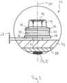
- FIG 1 shows a screw connection 10 with a fixed or sliding point screw 12 according to the invention.
- the fixed or sliding point screw 12 has a screw head 14 and a screw shank 16 .
- the screw head 14 has a torque transmission section 18 designed as an external hexagon, by means of which the fixed point or sliding point screw 12 can be driven to rotate about a screw axis 20 which is arranged concentrically with the screw head 14 and the screw shank 16 .
- the fixed or sliding point screw 12 is designed as a drilling screw, the screw shank 16 having a drilling point 22 and a threaded section 24 with a self-tapping thread 26 .
- the screw head 14 At its end facing the threaded section 26 , the screw head 14 has a collar section 28 on which the screw head 14 widens in the radial direction, i.e. perpendicularly to the screw axis 20 .
- the collar section 28 On its side facing away from the torque transmission section 18 , the collar section 28 has a contact surface 30 which is arranged in a plane perpendicular to the screw axis 20 .
- a buffer element 32 made of an elastic ethylene-propylene-diene rubber (EPDM) is arranged on the side of the collar section 28 facing away from the torque transmission section 18 .
- the buffer element 32 has two flat surfaces 34, 36, which are arranged parallel to each other and perpendicular to the screw axis 20.
- a sliding disk 38 which also has two planar surfaces 40 , 42 which are arranged parallel to one another and perpendicular to the screw axis 20 .
- the sliding disc 38 is made of metal, preferably stainless steel, or a plastic.
- the screw head 14 and the screw shank 16 are made of stainless steel, with the sliding disk 38 having a Teflon coating on the side 40 facing away from the buffer element 32 . If the sliding disk 38 is made of a plastic, it is also conceivable that the sliding disk 38 is made of Teflon.
- the buffer element 32 is designed as a ring and thus encompasses the screw shank 16 in the radial direction.
- the screw shank 16 has an unthreaded section 44 which is arranged between the threaded section 24 and the screw head 14 .
- the sliding disk 38 has an outer diameter 46 , the collar section 28 having a collar diameter 48 .
- the buffer element 32 has a buffer element diameter 50 .
- the outside diameter 46, the collar diameter 48 and the buffer element diameter 50 are designed in such a way that the collar section 28 and the sliding disk 38 cover the buffer element 32 radially.
- the outer diameter 46 is advantageously larger than the collar diameter 48, so that an optical tightening check can be made possible, which is used for checking a tightening torque and/or a screw-in depth of the fixed or sliding point screw 12 is designed.
- the achievement of the optimal tightening torque and/or the optimal screw-in depth can be determined by the fact that the sliding washer 38 is completely covered by the buffer element 32 when the optimal tightening torque and/or the optimal screw-in depth is reached when the buffer element 32 is squeezed between sliding disk 38 and collar portion 28.
- the sliding disk 38 also has an inner diameter (no reference number), the screw shank 16 having a circular-cylindrical shank collar 51 with a shank diameter 52 .
- the shank diameter 52 is larger than a thread diameter 53 in the area of the threaded section 24.
- the inner diameter of the sliding disk 38 also corresponds to the shank diameter 52 in such a way that the buffer element 32 cannot be pressed between a gap between the sliding disk 38 and the screw shank 16 and thus destroyed during screwing.
- the screw head 14, the buffer element 32 and the sliding washer 38 are preferably connected to one another by gluing or vulcanizing, with the screw head 14 being connected to the buffer element 32 and with the Buffer element 32 is in turn connected to the sliding disk 38 .
- the screw connection 10 also has a first component 54, for example a sheet metal profile designed as a wall bracket and having a thickness 56.
- the screw connection 10 also has a second component 58, for example a sheet metal profile designed as a support profile and having a thickness 60.
- Wall brackets 54 and support profiles 58 of this type are used in curtain-type, rear-ventilated facades.
- the wall bracket 54 has a sliding point 62 designed as a slot, the fixed or sliding point screw 12 being inserted through the pre-punched slot 62 through the wall bracket 54 and screwed to the support profile 58 .
- An internal thread 64 is introduced into the support profile 58 by means of the drill bit 22 and the self-tapping thread 26 .
- the wall bracket 54 In addition to the elongated hole 62, the wall bracket 54 also has round holes designed as a fixed point, with the fixed or sliding point screw 12 being able to be inserted through the elongated holes 62 and the round holes, and the wall bracket 54 also being screwed to the support profile 58 in this way.
- the fixed or Sliding point screw 12 When screwing with a fixed point, the fixed or Sliding point screw 12 has the advantage of ensuring a so-called "soft screw joint" in order to prevent stripping of the thread 26.
- the fixed or sliding point screw 12 can be used due to the elasticity or compressibility of the buffer element 32 in screw connections 10 with different component combinations, ie with different thicknesses 56, 60 of the first and second components 54, 58, whereby due to of the sliding disk 38, on the one hand, protection of the buffer element 32 and, on the other hand, easy sliding on, in particular, metallic components 54 can be achieved since the connection cannot be tightened too much.
- a screw connection is also referred to as a so-called "soft screw connection”.
- components made of plastic to be screwed together.
- the circular-cylindrical shank collar 51 advantageously has an axial length that is smaller than the thickness 56 of the wall holder 54.
- FIGs 3 to 6 is shown in each case a section of a screw connection 10 according to the invention, wherein figure 3 an enlarged section of the screw connection 10 according to figure 1 shows with not fully screwed fixed or sliding point screw 12 and where figure 4 according to the cut figure 3 with the correct screw-in depth and/or correct tightening torque and where figure 5 according to the cut figure 3 and 4 with overtightened fixed or sliding point screw 12 shows and where figure 6 the excerpt according to the Figures 3 to 5 with tilted fixed or sliding point screw 12 shows.
- Corresponding reference symbols in the figures are given the corresponding reference symbols Figures 1 and 2 Mistake.
- the buffer element diameter 50 is selected to be smaller than the collar diameter 48 of the collar section 28. If, as in figure 3 is clearly visible, the fixed or sliding point screw 12 is not fully screwed into the second component 58, the buffer element 32 is not compressed between collar portion 28 and sliding disk 38, wherein consequently the buffer element diameter 50 is not increased. A gap 68 thus remains between the sliding disk 38 and the first component 54.
- figure 5 shows the screw connection 10 when the correct screw-in depth and/or the correct tightening torque has been exceeded.
- the buffer element 32 is then compressed to such an extent that the buffer element diameter 50 far exceeds the outer diameter 46 of the sliding disk 38 . In this way, a visual tightening check can be implemented overall.
- FIG 6 is the screw axis 20 relative to an axis arranged perpendicularly to the first and/or second component 54, 58 72 arranged tilted by an angle 74.
- Such tilting can be caused, for example, by the fixed or sliding point screw not being screwed in exactly coaxially with respect to the surface of the first component 54 or by the thread pitch of the thread 26 .
- the tilting can be compensated for by the buffer element 32 , so that the sliding disk 38 always rests over its entire surface on the surface of the first component 54 , so that the second component 58 rests against the first component 54 over its entire surface.
- the buffer element 32 can also be used to compensate for thermally induced expansions or changes in the thickness 56, 60 of the first and second components 54, 58, so that the screw connection 12 can always slide in the slot 62. In the event of a fire, the buffer element 32 can melt, so that the screw connection 12 is loosened overall, with a rear-ventilated curtain wall being able to be dismantled particularly easily.
Landscapes
- Engineering & Computer Science (AREA)
- General Engineering & Computer Science (AREA)
- Mechanical Engineering (AREA)
- Connection Of Plates (AREA)
- Bolts, Nuts, And Washers (AREA)
- Lubricants (AREA)
Priority Applications (2)
| Application Number | Priority Date | Filing Date | Title |
|---|---|---|---|
| HRP20220480TT HRP20220480T1 (hr) | 2015-12-04 | 2016-12-01 | Fiksni ili klizni vijak |
| PL16805102T PL3384166T3 (pl) | 2015-12-04 | 2016-12-01 | Wkręt do punktów stałych i przesuwnych |
Applications Claiming Priority (2)
| Application Number | Priority Date | Filing Date | Title |
|---|---|---|---|
| DE102015224367.2A DE102015224367A1 (de) | 2015-12-04 | 2015-12-04 | Fest- oder Gleitpunktschraube |
| PCT/EP2016/079375 WO2017093374A1 (de) | 2015-12-04 | 2016-12-01 | Fest- oder gleitpunktschraube |
Publications (2)
| Publication Number | Publication Date |
|---|---|
| EP3384166A1 EP3384166A1 (de) | 2018-10-10 |
| EP3384166B1 true EP3384166B1 (de) | 2022-01-19 |
Family
ID=57460511
Family Applications (1)
| Application Number | Title | Priority Date | Filing Date |
|---|---|---|---|
| EP16805102.7A Active EP3384166B1 (de) | 2015-12-04 | 2016-12-01 | Fest- oder gleitpunktschraube |
Country Status (6)
| Country | Link |
|---|---|
| US (1) | US10954978B2 (pl) |
| EP (1) | EP3384166B1 (pl) |
| DE (1) | DE102015224367A1 (pl) |
| HR (1) | HRP20220480T1 (pl) |
| PL (1) | PL3384166T3 (pl) |
| WO (1) | WO2017093374A1 (pl) |
Families Citing this family (2)
| Publication number | Priority date | Publication date | Assignee | Title |
|---|---|---|---|---|
| PL3581319T3 (pl) | 2018-05-09 | 2024-07-08 | Brigham Young University | Układ i sposób spajania tarciowego za pomocą koronki tarciowej |
| FR3092882B1 (fr) * | 2019-02-19 | 2022-10-14 | Lionel Utille | Dispositif de visualisation de perte de tension dans un assemblage |
Family Cites Families (16)
| Publication number | Priority date | Publication date | Assignee | Title |
|---|---|---|---|---|
| US3021747A (en) * | 1953-03-19 | 1962-02-20 | Goodyear Tire & Rubber | Method and washer means including a calibrated rubber layer for measuring bolt tension |
| US3216303A (en) | 1963-12-03 | 1965-11-09 | Melzer Franklin | Load sensing and indicating means |
| DE1925415U (de) * | 1965-06-12 | 1965-10-14 | Erwin Sponagl | Unterlegscheibe fuer schraubenverbindungen. |
| DE1650988A1 (de) * | 1968-03-06 | 1970-12-03 | Langen & Co | Dichtungsmittel |
| US3500712A (en) * | 1968-07-11 | 1970-03-17 | Illinois Tool Works | Sealing washer unit |
| US4322193A (en) * | 1980-06-09 | 1982-03-30 | Stahl Keith E | Tension gauge |
| GB2120795A (en) | 1982-05-06 | 1983-12-07 | Priest And Sons Ltd Benjamin | Load-indicating washer |
| CA2140475C (en) * | 1995-01-18 | 2000-03-07 | Uli Walther | Screw |
| GB2330638B (en) * | 1997-10-23 | 2001-09-26 | Pandrol Ltd | Fastening device |
| US6729819B2 (en) * | 2002-07-03 | 2004-05-04 | Applied Bolting Technology Products, Inc. | Bolt lubricating device and method |
| WO2007118941A1 (fr) * | 2006-04-19 | 2007-10-25 | Lionel Utille | Dispositif de visualisation du bon effort de serrage d'un ecrou monte sur une tige filetee |
| DE102006041860B4 (de) | 2006-09-06 | 2009-05-14 | Sfs Intec Holding Ag | Schraube und deren Kombination mit einer konischen Dichtscheibe |
| DE102008045412A1 (de) | 2008-09-02 | 2010-03-04 | Sfs Intec Holding Ag | Schraube und damit hergestellte Verbindung zwischen einem Profil und einer Aussenwand |
| DE102013002631B4 (de) * | 2013-02-15 | 2023-08-31 | Audi Ag | Bauteilverbindung für ein Anbauteil an einem Trägerteil |
| DE102014000940A1 (de) * | 2014-01-23 | 2015-07-23 | Sfs Intec Holding Ag | Schraube, Befestigungsanordnung und Verwendung einer Schraube |
| US9574597B2 (en) * | 2014-06-30 | 2017-02-21 | Lenovo Enterprise Solutions (Singapore) Pte. Ltd. | Fastening device |
-
2015
- 2015-12-04 DE DE102015224367.2A patent/DE102015224367A1/de not_active Withdrawn
-
2016
- 2016-12-01 HR HRP20220480TT patent/HRP20220480T1/hr unknown
- 2016-12-01 EP EP16805102.7A patent/EP3384166B1/de active Active
- 2016-12-01 US US15/780,330 patent/US10954978B2/en active Active
- 2016-12-01 WO PCT/EP2016/079375 patent/WO2017093374A1/de not_active Ceased
- 2016-12-01 PL PL16805102T patent/PL3384166T3/pl unknown
Also Published As
| Publication number | Publication date |
|---|---|
| US10954978B2 (en) | 2021-03-23 |
| PL3384166T3 (pl) | 2022-04-04 |
| DE102015224367A8 (de) | 2017-08-10 |
| WO2017093374A1 (de) | 2017-06-08 |
| HRP20220480T1 (hr) | 2022-05-27 |
| EP3384166A1 (de) | 2018-10-10 |
| DE102015224367A1 (de) | 2017-06-08 |
| US20180347605A1 (en) | 2018-12-06 |
Similar Documents
| Publication | Publication Date | Title |
|---|---|---|
| EP2049807B1 (de) | Vorrichtung zum befestigen eines anbauteiles und eines trägerteiles in einem abstand voneinander | |
| DE102008033509A1 (de) | Schraube | |
| DE102013215291A1 (de) | Gewindebuchse zum Einschrauben | |
| EP3415773B1 (de) | Schraube mit einem mehrgängigen unterkopfgewinde und befestigungsanordnung hierzu | |
| EP3097313A1 (de) | Schraube, befestigungsanordnung und verwendung einer schraube | |
| EP2185827B1 (de) | Montageschraube und befestigungsanordnung mit einem hohlkammerprofil | |
| EP3384166B1 (de) | Fest- oder gleitpunktschraube | |
| EP2000681A2 (de) | Stützhülse | |
| DE102008010606A1 (de) | Befestigungselement für Holzfaserdämmplatten | |
| EP3374649B1 (de) | Gewindeformende schraube | |
| DE102012215645B4 (de) | Schraube und ihre Verwendung | |
| DE102013200999A1 (de) | Toleranzausgleichsvorrichtung | |
| DE102012204872A1 (de) | Anordnung mit einstellbarem Kompressionslastbegrenzer | |
| EP2930378B2 (de) | Distanzbefestigungselement | |
| DE20218699U1 (de) | Vorrichtung zur Befestigung von Beschlagteilen an Mehrkammerprofilen | |
| EP2667041A1 (de) | Befestigungssatz für ein Faserverbundbauteil | |
| DE102016101519A1 (de) | Schraube, Befestigungsanordnung, Verwendung einer Befestigungsanordnung und Verfahren zum Herstellen einer Schraube | |
| EP3097314B1 (de) | Verfahren zum herstellen einer befestigungsanordnung und verwendung einer schraube zum herstellen einer befestigungsanordnung | |
| EP2339188A2 (de) | Befestigungsschraube zum Verbinden von Dämmstoffplatten | |
| EP2405146A1 (de) | Montagevorrichtung zur Befestigung einer Baugruppe an einem Bauteil, insbesondere einem Außengehäuse einer weiteren Baugruppe | |
| DE102016209395A1 (de) | Befestigungselement für den Toleranzausgleich | |
| DE202012103721U1 (de) | Montageschraube zur Befestigung von Beschlagteilen, insbesondere von Bandteilen an Hohlkammerprofilen und einem Hohlkammerprofil | |
| EP1990553B1 (de) | Beschlagschraube, insbesondere für Möbel-Beschläge | |
| DE102017217740A1 (de) | Schraube | |
| DE102017002069B4 (de) | Befestigungssystem mit einem Einschraubdübel |
Legal Events
| Date | Code | Title | Description |
|---|---|---|---|
| REG | Reference to a national code |
Ref country code: HR Ref legal event code: TUEP Ref document number: P20220480 Country of ref document: HR |
|
| STAA | Information on the status of an ep patent application or granted ep patent |
Free format text: STATUS: UNKNOWN |
|
| STAA | Information on the status of an ep patent application or granted ep patent |
Free format text: STATUS: THE INTERNATIONAL PUBLICATION HAS BEEN MADE |
|
| PUAI | Public reference made under article 153(3) epc to a published international application that has entered the european phase |
Free format text: ORIGINAL CODE: 0009012 |
|
| STAA | Information on the status of an ep patent application or granted ep patent |
Free format text: STATUS: REQUEST FOR EXAMINATION WAS MADE |
|
| 17P | Request for examination filed |
Effective date: 20180529 |
|
| AK | Designated contracting states |
Kind code of ref document: A1 Designated state(s): AL AT BE BG CH CY CZ DE DK EE ES FI FR GB GR HR HU IE IS IT LI LT LU LV MC MK MT NL NO PL PT RO RS SE SI SK SM TR |
|
| AX | Request for extension of the european patent |
Extension state: BA ME |
|
| DAV | Request for validation of the european patent (deleted) | ||
| DAX | Request for extension of the european patent (deleted) | ||
| GRAP | Despatch of communication of intention to grant a patent |
Free format text: ORIGINAL CODE: EPIDOSNIGR1 |
|
| STAA | Information on the status of an ep patent application or granted ep patent |
Free format text: STATUS: GRANT OF PATENT IS INTENDED |
|
| INTG | Intention to grant announced |
Effective date: 20210602 |
|
| GRAJ | Information related to disapproval of communication of intention to grant by the applicant or resumption of examination proceedings by the epo deleted |
Free format text: ORIGINAL CODE: EPIDOSDIGR1 |
|
| STAA | Information on the status of an ep patent application or granted ep patent |
Free format text: STATUS: REQUEST FOR EXAMINATION WAS MADE |
|
| GRAS | Grant fee paid |
Free format text: ORIGINAL CODE: EPIDOSNIGR3 |
|
| STAA | Information on the status of an ep patent application or granted ep patent |
Free format text: STATUS: GRANT OF PATENT IS INTENDED |
|
| GRAP | Despatch of communication of intention to grant a patent |
Free format text: ORIGINAL CODE: EPIDOSNIGR1 |
|
| INTC | Intention to grant announced (deleted) | ||
| INTG | Intention to grant announced |
Effective date: 20211104 |
|
| GRAA | (expected) grant |
Free format text: ORIGINAL CODE: 0009210 |
|
| STAA | Information on the status of an ep patent application or granted ep patent |
Free format text: STATUS: THE PATENT HAS BEEN GRANTED |
|
| AK | Designated contracting states |
Kind code of ref document: B1 Designated state(s): AL AT BE BG CH CY CZ DE DK EE ES FI FR GB GR HR HU IE IS IT LI LT LU LV MC MK MT NL NO PL PT RO RS SE SI SK SM TR |
|
| REG | Reference to a national code |
Ref country code: GB Ref legal event code: FG4D Free format text: NOT ENGLISH |
|
| REG | Reference to a national code |
Ref country code: CH Ref legal event code: EP |
|
| REG | Reference to a national code |
Ref country code: DE Ref legal event code: R096 Ref document number: 502016014438 Country of ref document: DE |
|
| REG | Reference to a national code |
Ref country code: AT Ref legal event code: REF Ref document number: 1463945 Country of ref document: AT Kind code of ref document: T Effective date: 20220215 |
|
| REG | Reference to a national code |
Ref country code: IE Ref legal event code: FG4D Free format text: LANGUAGE OF EP DOCUMENT: GERMAN |
|
| REG | Reference to a national code |
Ref country code: RO Ref legal event code: EPE |
|
| REG | Reference to a national code |
Ref country code: LT Ref legal event code: MG9D |
|
| REG | Reference to a national code |
Ref country code: NL Ref legal event code: MP Effective date: 20220119 |
|
| REG | Reference to a national code |
Ref country code: HR Ref legal event code: T1PR Ref document number: P20220480 Country of ref document: HR |
|
| PG25 | Lapsed in a contracting state [announced via postgrant information from national office to epo] |
Ref country code: NL Free format text: LAPSE BECAUSE OF FAILURE TO SUBMIT A TRANSLATION OF THE DESCRIPTION OR TO PAY THE FEE WITHIN THE PRESCRIBED TIME-LIMIT Effective date: 20220119 |
|
| PG25 | Lapsed in a contracting state [announced via postgrant information from national office to epo] |
Ref country code: SE Free format text: LAPSE BECAUSE OF FAILURE TO SUBMIT A TRANSLATION OF THE DESCRIPTION OR TO PAY THE FEE WITHIN THE PRESCRIBED TIME-LIMIT Effective date: 20220119 Ref country code: RS Free format text: LAPSE BECAUSE OF FAILURE TO SUBMIT A TRANSLATION OF THE DESCRIPTION OR TO PAY THE FEE WITHIN THE PRESCRIBED TIME-LIMIT Effective date: 20220119 Ref country code: PT Free format text: LAPSE BECAUSE OF FAILURE TO SUBMIT A TRANSLATION OF THE DESCRIPTION OR TO PAY THE FEE WITHIN THE PRESCRIBED TIME-LIMIT Effective date: 20220519 Ref country code: NO Free format text: LAPSE BECAUSE OF FAILURE TO SUBMIT A TRANSLATION OF THE DESCRIPTION OR TO PAY THE FEE WITHIN THE PRESCRIBED TIME-LIMIT Effective date: 20220419 Ref country code: LT Free format text: LAPSE BECAUSE OF FAILURE TO SUBMIT A TRANSLATION OF THE DESCRIPTION OR TO PAY THE FEE WITHIN THE PRESCRIBED TIME-LIMIT Effective date: 20220119 Ref country code: ES Free format text: LAPSE BECAUSE OF FAILURE TO SUBMIT A TRANSLATION OF THE DESCRIPTION OR TO PAY THE FEE WITHIN THE PRESCRIBED TIME-LIMIT Effective date: 20220119 Ref country code: BG Free format text: LAPSE BECAUSE OF FAILURE TO SUBMIT A TRANSLATION OF THE DESCRIPTION OR TO PAY THE FEE WITHIN THE PRESCRIBED TIME-LIMIT Effective date: 20220419 |
|
| PG25 | Lapsed in a contracting state [announced via postgrant information from national office to epo] |
Ref country code: LV Free format text: LAPSE BECAUSE OF FAILURE TO SUBMIT A TRANSLATION OF THE DESCRIPTION OR TO PAY THE FEE WITHIN THE PRESCRIBED TIME-LIMIT Effective date: 20220119 Ref country code: GR Free format text: LAPSE BECAUSE OF FAILURE TO SUBMIT A TRANSLATION OF THE DESCRIPTION OR TO PAY THE FEE WITHIN THE PRESCRIBED TIME-LIMIT Effective date: 20220420 Ref country code: FI Free format text: LAPSE BECAUSE OF FAILURE TO SUBMIT A TRANSLATION OF THE DESCRIPTION OR TO PAY THE FEE WITHIN THE PRESCRIBED TIME-LIMIT Effective date: 20220119 |
|
| PG25 | Lapsed in a contracting state [announced via postgrant information from national office to epo] |
Ref country code: IS Free format text: LAPSE BECAUSE OF FAILURE TO SUBMIT A TRANSLATION OF THE DESCRIPTION OR TO PAY THE FEE WITHIN THE PRESCRIBED TIME-LIMIT Effective date: 20220519 |
|
| REG | Reference to a national code |
Ref country code: DE Ref legal event code: R097 Ref document number: 502016014438 Country of ref document: DE |
|
| PG25 | Lapsed in a contracting state [announced via postgrant information from national office to epo] |
Ref country code: SM Free format text: LAPSE BECAUSE OF FAILURE TO SUBMIT A TRANSLATION OF THE DESCRIPTION OR TO PAY THE FEE WITHIN THE PRESCRIBED TIME-LIMIT Effective date: 20220119 Ref country code: EE Free format text: LAPSE BECAUSE OF FAILURE TO SUBMIT A TRANSLATION OF THE DESCRIPTION OR TO PAY THE FEE WITHIN THE PRESCRIBED TIME-LIMIT Effective date: 20220119 Ref country code: DK Free format text: LAPSE BECAUSE OF FAILURE TO SUBMIT A TRANSLATION OF THE DESCRIPTION OR TO PAY THE FEE WITHIN THE PRESCRIBED TIME-LIMIT Effective date: 20220119 Ref country code: CZ Free format text: LAPSE BECAUSE OF FAILURE TO SUBMIT A TRANSLATION OF THE DESCRIPTION OR TO PAY THE FEE WITHIN THE PRESCRIBED TIME-LIMIT Effective date: 20220119 |
|
| PLBE | No opposition filed within time limit |
Free format text: ORIGINAL CODE: 0009261 |
|
| STAA | Information on the status of an ep patent application or granted ep patent |
Free format text: STATUS: NO OPPOSITION FILED WITHIN TIME LIMIT |
|
| PG25 | Lapsed in a contracting state [announced via postgrant information from national office to epo] |
Ref country code: AL Free format text: LAPSE BECAUSE OF FAILURE TO SUBMIT A TRANSLATION OF THE DESCRIPTION OR TO PAY THE FEE WITHIN THE PRESCRIBED TIME-LIMIT Effective date: 20220119 |
|
| REG | Reference to a national code |
Ref country code: HR Ref legal event code: ODRP Ref document number: P20220480 Country of ref document: HR Payment date: 20221123 Year of fee payment: 7 |
|
| 26N | No opposition filed |
Effective date: 20221020 |
|
| PG25 | Lapsed in a contracting state [announced via postgrant information from national office to epo] |
Ref country code: SI Free format text: LAPSE BECAUSE OF FAILURE TO SUBMIT A TRANSLATION OF THE DESCRIPTION OR TO PAY THE FEE WITHIN THE PRESCRIBED TIME-LIMIT Effective date: 20220119 |
|
| REG | Reference to a national code |
Ref country code: BE Ref legal event code: MM Effective date: 20221231 |
|
| PG25 | Lapsed in a contracting state [announced via postgrant information from national office to epo] |
Ref country code: LU Free format text: LAPSE BECAUSE OF NON-PAYMENT OF DUE FEES Effective date: 20221201 |
|
| PG25 | Lapsed in a contracting state [announced via postgrant information from national office to epo] |
Ref country code: IE Free format text: LAPSE BECAUSE OF NON-PAYMENT OF DUE FEES Effective date: 20221201 |
|
| PG25 | Lapsed in a contracting state [announced via postgrant information from national office to epo] |
Ref country code: BE Free format text: LAPSE BECAUSE OF NON-PAYMENT OF DUE FEES Effective date: 20221231 |
|
| REG | Reference to a national code |
Ref country code: HR Ref legal event code: ODRP Ref document number: P20220480 Country of ref document: HR Payment date: 20231123 Year of fee payment: 8 |
|
| PGFP | Annual fee paid to national office [announced via postgrant information from national office to epo] |
Ref country code: SK Payment date: 20231130 Year of fee payment: 8 |
|
| PGFP | Annual fee paid to national office [announced via postgrant information from national office to epo] |
Ref country code: RO Payment date: 20231127 Year of fee payment: 8 |
|
| PG25 | Lapsed in a contracting state [announced via postgrant information from national office to epo] |
Ref country code: HU Free format text: LAPSE BECAUSE OF FAILURE TO SUBMIT A TRANSLATION OF THE DESCRIPTION OR TO PAY THE FEE WITHIN THE PRESCRIBED TIME-LIMIT; INVALID AB INITIO Effective date: 20161201 |
|
| P01 | Opt-out of the competence of the unified patent court (upc) registered |
Effective date: 20240320 |
|
| PG25 | Lapsed in a contracting state [announced via postgrant information from national office to epo] |
Ref country code: CY Free format text: LAPSE BECAUSE OF FAILURE TO SUBMIT A TRANSLATION OF THE DESCRIPTION OR TO PAY THE FEE WITHIN THE PRESCRIBED TIME-LIMIT Effective date: 20220119 |
|
| PG25 | Lapsed in a contracting state [announced via postgrant information from national office to epo] |
Ref country code: MK Free format text: LAPSE BECAUSE OF FAILURE TO SUBMIT A TRANSLATION OF THE DESCRIPTION OR TO PAY THE FEE WITHIN THE PRESCRIBED TIME-LIMIT Effective date: 20220119 |
|
| PG25 | Lapsed in a contracting state [announced via postgrant information from national office to epo] |
Ref country code: MC Free format text: LAPSE BECAUSE OF FAILURE TO SUBMIT A TRANSLATION OF THE DESCRIPTION OR TO PAY THE FEE WITHIN THE PRESCRIBED TIME-LIMIT Effective date: 20220119 |
|
| PG25 | Lapsed in a contracting state [announced via postgrant information from national office to epo] |
Ref country code: MC Free format text: LAPSE BECAUSE OF FAILURE TO SUBMIT A TRANSLATION OF THE DESCRIPTION OR TO PAY THE FEE WITHIN THE PRESCRIBED TIME-LIMIT Effective date: 20220119 |
|
| PG25 | Lapsed in a contracting state [announced via postgrant information from national office to epo] |
Ref country code: MT Free format text: LAPSE BECAUSE OF FAILURE TO SUBMIT A TRANSLATION OF THE DESCRIPTION OR TO PAY THE FEE WITHIN THE PRESCRIBED TIME-LIMIT Effective date: 20220119 |
|
| PGFP | Annual fee paid to national office [announced via postgrant information from national office to epo] |
Ref country code: PL Payment date: 20241118 Year of fee payment: 9 |
|
| PGFP | Annual fee paid to national office [announced via postgrant information from national office to epo] |
Ref country code: GB Payment date: 20241212 Year of fee payment: 9 |
|
| REG | Reference to a national code |
Ref country code: HR Ref legal event code: ODRP Ref document number: P20220480 Country of ref document: HR Payment date: 20241223 Year of fee payment: 9 |
|
| PGFP | Annual fee paid to national office [announced via postgrant information from national office to epo] |
Ref country code: FR Payment date: 20241219 Year of fee payment: 9 |
|
| PGFP | Annual fee paid to national office [announced via postgrant information from national office to epo] |
Ref country code: AT Payment date: 20241213 Year of fee payment: 9 |
|
| PGFP | Annual fee paid to national office [announced via postgrant information from national office to epo] |
Ref country code: HR Payment date: 20241223 Year of fee payment: 9 |
|
| PGFP | Annual fee paid to national office [announced via postgrant information from national office to epo] |
Ref country code: IT Payment date: 20241216 Year of fee payment: 9 |
|
| PGFP | Annual fee paid to national office [announced via postgrant information from national office to epo] |
Ref country code: DE Payment date: 20250212 Year of fee payment: 9 |
|
| PGFP | Annual fee paid to national office [announced via postgrant information from national office to epo] |
Ref country code: CH Payment date: 20250101 Year of fee payment: 9 |
|
| PGFP | Annual fee paid to national office [announced via postgrant information from national office to epo] |
Ref country code: TR Payment date: 20241219 Year of fee payment: 9 |
|
| REG | Reference to a national code |
Ref country code: SK Ref legal event code: MM4A Ref document number: E 39456 Country of ref document: SK Effective date: 20241201 |
|
| PG25 | Lapsed in a contracting state [announced via postgrant information from national office to epo] |
Ref country code: RO Free format text: LAPSE BECAUSE OF NON-PAYMENT OF DUE FEES Effective date: 20241201 |
|
| PG25 | Lapsed in a contracting state [announced via postgrant information from national office to epo] |
Ref country code: SK Free format text: LAPSE BECAUSE OF NON-PAYMENT OF DUE FEES Effective date: 20241201 |