EP3384102B1 - Dispositif d'assistance au franchissement d'un obstacle par un véhicule - Google Patents
Dispositif d'assistance au franchissement d'un obstacle par un véhicule Download PDFInfo
- Publication number
- EP3384102B1 EP3384102B1 EP16813094.6A EP16813094A EP3384102B1 EP 3384102 B1 EP3384102 B1 EP 3384102B1 EP 16813094 A EP16813094 A EP 16813094A EP 3384102 B1 EP3384102 B1 EP 3384102B1
- Authority
- EP
- European Patent Office
- Prior art keywords
- plate
- arm
- frame
- carriage
- flap
- Prior art date
- Legal status (The legal status is an assumption and is not a legal conclusion. Google has not performed a legal analysis and makes no representation as to the accuracy of the status listed.)
- Active
Links
- 239000002184 metal Substances 0.000 claims description 13
- 230000000284 resting effect Effects 0.000 claims description 8
- 230000003321 amplification Effects 0.000 claims description 6
- 238000003199 nucleic acid amplification method Methods 0.000 claims description 6
- 230000001771 impaired effect Effects 0.000 claims 1
- 229910000831 Steel Inorganic materials 0.000 description 9
- 239000010959 steel Substances 0.000 description 9
- 238000006073 displacement reaction Methods 0.000 description 7
- 238000010276 construction Methods 0.000 description 4
- 238000009434 installation Methods 0.000 description 4
- 125000006850 spacer group Chemical group 0.000 description 4
- 239000002689 soil Substances 0.000 description 3
- 230000008901 benefit Effects 0.000 description 2
- 239000011248 coating agent Substances 0.000 description 2
- 238000000576 coating method Methods 0.000 description 2
- 230000007423 decrease Effects 0.000 description 2
- 238000005096 rolling process Methods 0.000 description 2
- 239000007787 solid Substances 0.000 description 2
- 238000003466 welding Methods 0.000 description 2
- 238000005452 bending Methods 0.000 description 1
- 230000033228 biological regulation Effects 0.000 description 1
- 239000011449 brick Substances 0.000 description 1
- 230000000295 complement effect Effects 0.000 description 1
- 238000005520 cutting process Methods 0.000 description 1
- 238000005034 decoration Methods 0.000 description 1
- 238000001514 detection method Methods 0.000 description 1
- 230000000694 effects Effects 0.000 description 1
- 230000003028 elevating effect Effects 0.000 description 1
- 230000007613 environmental effect Effects 0.000 description 1
- 230000001856 erectile effect Effects 0.000 description 1
- 230000014509 gene expression Effects 0.000 description 1
- 230000005484 gravity Effects 0.000 description 1
- 230000008595 infiltration Effects 0.000 description 1
- 238000001764 infiltration Methods 0.000 description 1
- 238000003780 insertion Methods 0.000 description 1
- 230000037431 insertion Effects 0.000 description 1
- 230000010354 integration Effects 0.000 description 1
- 239000007788 liquid Substances 0.000 description 1
- 238000004519 manufacturing process Methods 0.000 description 1
- 239000000463 material Substances 0.000 description 1
- 230000002093 peripheral effect Effects 0.000 description 1
- 239000004810 polytetrafluoroethylene Substances 0.000 description 1
- 229920001343 polytetrafluoroethylene Polymers 0.000 description 1
- 230000001105 regulatory effect Effects 0.000 description 1
- 239000004575 stone Substances 0.000 description 1
- 229920002994 synthetic fiber Polymers 0.000 description 1
Images

Classifications
-
- E—FIXED CONSTRUCTIONS
- E04—BUILDING
- E04F—FINISHING WORK ON BUILDINGS, e.g. STAIRS, FLOORS
- E04F11/00—Stairways, ramps, or like structures; Balustrades; Handrails
- E04F11/002—Ramps
-
- E—FIXED CONSTRUCTIONS
- E04—BUILDING
- E04F—FINISHING WORK ON BUILDINGS, e.g. STAIRS, FLOORS
- E04F11/00—Stairways, ramps, or like structures; Balustrades; Handrails
- E04F11/02—Stairways; Layouts thereof
- E04F11/04—Movable stairways, e.g. of loft ladders which may or may not be concealable or extensible
- E04F11/06—Movable stairways, e.g. of loft ladders which may or may not be concealable or extensible collapsible, e.g. folding, telescopic
-
- E—FIXED CONSTRUCTIONS
- E04—BUILDING
- E04F—FINISHING WORK ON BUILDINGS, e.g. STAIRS, FLOORS
- E04F11/00—Stairways, ramps, or like structures; Balustrades; Handrails
- E04F11/002—Ramps
- E04F2011/005—Ramps collapsible, e.g. folding, telescopic
-
- E—FIXED CONSTRUCTIONS
- E04—BUILDING
- E04F—FINISHING WORK ON BUILDINGS, e.g. STAIRS, FLOORS
- E04F11/00—Stairways, ramps, or like structures; Balustrades; Handrails
- E04F11/002—Ramps
- E04F2011/007—Ramps characterised by the supporting structure
Definitions
- the present invention relates to a device for assisting the crossing of one or more steps or a threshold by a vehicle, in particular for people with reduced mobility moving with the aid of a wheelchair or for those with reduced mobility. persons moving a wheeled cart intended for the transport of objects.
- Such a threshold has a height generally ranging from one to several tens of centimeters and constitutes an obstacle which is often insurmountable for a person with reduced mobility or for delivery trolleys.
- One solution for enabling such a step to be crossed by a vehicle or wheeled trolley consists in setting up an access ramp.
- a major constraint concerning the installation of such a ramp is the absence of permanent encroachment on the public road, sidewalk and / or roadway, passageway, etc.
- Deployable and retractable ramps provide valuable service but suffer from complex mechanics. Such ramps require a significant free distance of deployment restricting the possibilities of implementation. The sidewalk irregularities stress their structure.
- FR 2947224 describes a tilting telescopic ramp.
- GB 2 491 706 discloses a ramp according to the preamble of claim 1, having a tray at one end pivoting relative to a frame, providing a horizontal position and an inclined position, springs and a flap pivoting between a vertical position and a horizontal position respectively.
- a device for assisting the crossing of an obstacle by a wheeled vehicle, in particular for a person with reduced mobility comprises a stationary frame comprising a bottom and two parallel symmetrical side walls.
- the assistance device comprises a platform provided with two ends, a first end being movable between a high position and a low position in which said platform constitutes an access ramp.
- the assistance device comprises a drive assembly of said first end between a low position and a high position, said first end being supported by said drive assembly both in the low position and in the high position.
- Said drive assembly comprises a linear actuator mounted under the plate, provided with a stationary end adjacent to said second end and integral with the bottom, and with a movable end.
- Said drive assembly comprises a carriage movable in horizontal translation and driven by said jack, said carriage resting on slides mounted on the bottom of the frame, said carriage comprising two pushers.
- Said drive assembly comprises a pair of arms, the arms being symmetrical, each arm resting on one of the pushers of the carriage, each arm supporting the first end of the plate; in the retracted position of the actuator, the carriage being close to said second end, the arms being in the low position and the first end being in the ramp position, and in the extended position of the actuator, the carriage being close to said first end , the arms being in the high position and the first end being in the high position.
- the arms are pivotally mounted to the side walls of the frame on a common substantially horizontal axis.
- each arm being housed in one side of the frame.
- each arm comprises a body made from a cut sheet metal blank. Pivot operation is reliable. Manufacturing costs are contained.
- each arm comprises a finger receiving the thrust of the pusher of the carriage and a finger supporting the first end of the plate.
- the arm is simple in construction and takes up little space.
- the finger supporting the first end of the plate is provided with a bearing.
- the finger in contact with the pusher is provided with a bearing.
- the finger comprises a base and a pin passing through a bore in the body of the arm, the base being welded to said body.
- the fingers of an arm are connected by their ends opposite to said body.
- the rigidity of the arm is improved.
- each arm is mounted between a side wall of the frame and a cover parallel to said side wall, at least one circular arc opening being formed in said cover, the fingers projecting from said opening, the pivot axis of the arm being supported bilaterally.
- a single opening allows two fingers to pass.
- an opening is provided for each finger.
- each arm has a triangular shape, a vertex being located at the pivot axis.
- the arm can be manufactured by cutting sheet metal with complementary shapes reducing the loss of material.
- the triangle is isosceles.
- the angle formed between a straight line passing through the pivot axis of an arm and the pusher of the carriage, and a straight line passing through the pivot axis of an arm and the arm contact point -plateau is between 50 and 70 °.
- the straight line passing through the pivot axis of an arm and the pusher of the carriage has an angular travel, during the pivoting, of between 50 and 70 °.
- the horizontal displacement of the jack is transformed into a displacement with a vertical component for the plate with maximum force in the low position.
- the line passing through the pivot axis of an arm and the pusher of the carriage is inclined relative to the vertical, during the pivoting, by an angle of between -30 and + 30 ° .
- the pushers are kept compact.
- the height requirement is low.
- the carriage comprises a frame made of folded sheet metal.
- the frame comprises a base substantially parallel to the bottom of the stationary frame, a rear flange provided with an opening allowing the cylinder to pass through, and a front flange comprising two zones forming the pushers.
- the cart is reliable and robust.
- the front rim is substantially vertical.
- the amplification ratio of the arms is between 100 and 110%, preferably greater than 100 and less than 105%.
- the construction is compact. The stroke of the cylinder is limited.
- each arm is mounted on one side of the frame on an axis fixed to said frame.
- the binding is sturdy.
- the arms forming the connecting rods are mounted articulated to the carriage and to the plate.
- the tray includes a second end pivotally mounted behind the frame about a horizontal axis.
- the platform can be tilted to form an easily passable access slope.
- the frame includes two pivot axis segments supporting the second end of the deck and two pairs of vertical stages, each pair of stages supporting a pivot axis segment, the stage of one pair being spaced apart. of the other plate of said pair, the plates extending to the bottom of the frame so that the compressive forces are transferred to said bottom.
- the linear actuator is electric.
- the carriage has a generally rectangular shape with a length greater than its width, the length of the carriage being perpendicular to the side walls of the frame.
- the carriage rests on four guide rails.
- the guide rails rest on the bottom of the frame.
- the trolley can be fitted with runners or wheels resting on the slides.
- the carriage comprises a front edge provided with cutouts forming a housing for a frame of the tray in the low position.
- the frame comprises a mechanical stop limiting the travel of the carriage, the arrival at the stop causing a current draw from the electric jack capable of being detected by a pilot of the jack.
- the carriage and the movable end of the jack are connected in the vicinity of the edge of the carriage remote from the stationary end of the jack. The stability of the cart when moving is satisfactory.
- the frame of the carriage is made of sheet steel with a thickness of between 1 and 4 mm.
- the plate comprises a frame made of sheet steel with a thickness of between 1 and 4 mm.
- the frame is made of sheet steel with a thickness of between 1 and 4 mm.
- the arms are made of sheet steel with a thickness of between 1 and 4 mm.
- the shutter is made of sheet steel with a thickness of between 1 and 4 mm.
- the frame of the carriage, the frame, the shutter, the cover and the arms are made of sheet steel of the same thickness between 2 and 3.5 mm, for example 3 mm.
- the tray includes a frame and a top plate.
- the top plate can be used for rolling or supporting a coating.
- the frame of the tray comprises a lower surface resting on the arms.
- the assistance device comprises a flap forming the front face of the device in the high position of the tray and forming a second access ramp in the low position of the tray, the flap being pivotally mounted on the tray at the first. end of said plate.
- the assistance device comprises a shutter deployment mechanism, comprising at least one connecting rod comprising a front end articulated to the shutter, the articulation being distant from the top edge and from the bottom edge of said shutter, a rear end linked to a first slide mounted to slide in a linear slideway formed in the plate, and a central portion linked to a second slide mounted to slide in a slideway formed in one side of the frame, the connecting rod moving in a substantially vertical plane.
- the movement of the shutter slaved to the movement of the plate is provided by the same actuator.
- the slides are pins.
- the linear slide is substantially horizontal in the high position of the plate.
- the assistance device comprises a flap forming the front face of the device in the high position of the tray and forming a second access ramp in the low position of the tray, the flap being pivotally mounted on the tray at the first. end of said plate.
- the shutter prevents the intrusion of foreign bodies under the tray.
- the slide of the frame is in an arc of a circle with a substantially vertical lower end, preferably with a radius of between 30 and 280 mm.
- the mechanism is compact.
- the slide of the frame has an upper end inclined at an angle of between 50 and 75 ° with respect to the vertical.
- the movement of the shutter ensures a release towards the front at the beginning of the descent of the plate and a support on the ground of the free end of the shutter at the end of the descent.
- the hinge axis of the flap is arranged at a height of between 40 and 60% of the distance between the top edge and the bottom edge of said flap. If mounted higher, the torque exerted decreases significantly. If mounted lower, the joint may rub against the ground.
- the connecting rod is inclined at an angle of between 10 and 35 ° relative to the horizontal in the high position of the plate and the connecting rod is substantially horizontal in the low position of the plate.
- the assembly of the slide is simple.
- the connecting rod is made from a cut sheet metal blank.
- the connecting rod is economically manufactured.
- the connecting rod is a straight arm.
- the connecting rod is not subject to bending.
- the stroke of the connecting rod is less than the stroke of the free end of the shutter.
- the connecting rod can be simple and robust in shape.
- the linear slide provided in the plate comprises an elongated flat in which is formed a rectilinear opening housing the slide.
- the slide takes up the forces while avoiding buckling forces.
- said plate is formed by folding an edge of the plate.
- two symmetrical connecting rods are provided, one connecting rod per side of the frame. The risk of veiling the shutter is reduced.
- the shaft comprises a pin passing through a bore made in the body of the arm, and a base with a diameter greater than the diameter of the bore.
- the base can be welded to one side of the frame.
- the pin projects from the arm and comes into a bore made in a cover parallel to said side wall of the frame.
- the frame comprises at least one sheet disposed between said side wall and the cover.
- the sheet stiffens said side.
- the sheet may be provided with holes equivalent to the holes in the cover and form an extra thickness providing an assembly clearance.
- the object of the invention is to make it possible to cross a height difference resulting in a step.
- the two levels will be distinguished by the expressions upper floor and lower floor.
- the entrance to a room, a shop, an office often has a height offset from the outside, whether it is a street open to car traffic, a passage pedestrian, a square, etc. People in wheelchairs must be able to access this type of building. Delivery people with rolling trays or trolleys have the same need.
- To cross a height of one or two steps heavy lift-type installations are not suitable. It is also necessary to respect the appearance of the facades, often subject to protection regulations, and their alignment.
- the structure of the building must be preserved as much as possible, in particular the supporting structure of the upper floor of the ground floor into which entry must be made easy.
- a notable constraint comes from the frequent unavailability of the basement, used for other purposes or held by third parties.
- the space available in height is limited.
- the assistance device 1 aims to ensure the installation of a ramp having a slope of less than 20%, or even less than 15, 10 or 5% depending on regulatory or environmental constraints.
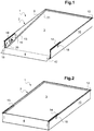
- the assistance device 1 is intended to be inserted or embedded in the upper floor, in front of the lower floor at the level of the access to be crossed.
- the assistance device 1 comprises a frame 2 forming a box 7 inside which the ramp is housed.
- the ramp may have an elevating end, the ramp then being tiltable as illustrated in the drawings.
- the frame 2 has a generally substantially parallelepipedal shape with dimensions adapted to the height of the step, the width of the access and the dimensions of the vehicle envisaged.
- the box may have a height of the order of 5 to 30 centimeters allowing insertion into most soils and floors, such as a concrete, brick or other slab.
- the assistance device 1 comprises a plate 3 mounted in the frame 2.
- the upper plate constitutes a cover panel.
- the frame 2 is installed so that the upper plate forms a surface flush with the upper floor of the room.
- the board 3 can be realized in such a way as to be harmonized with the rest of the upper floor, for example respecting the geometry, the covering, the decoration, etc.
- the assistance device 1 comprises a front flap 4 forming a front surface of the step.
- the front flap 4 is generally vertical in the high or rest position of the assistance device 1.
- the front flap 4 is tilted in the active or low position of the assistance device 1.
- the front face 4 of the device 1 can also have an appearance. chosen for integration into the facade of the building.
- the frame 2 is stationary in the sense that it forms a stationary structure of the assistance device 1 with respect to its installation environment such as the ground or the sidewalk.
- the frame 2 comprises a bottom 8, parallel side walls 9, 10 forming the sides, a rear wall 11 and support elements for the plate 3.
- the term " rear” is used here as opposed to the front of the device. assistance 1 intended to come in the vicinity of a lower floor, for example on the front of the building.
- the term “rear” can also be seen as synonymous with " interior " in the case of a building.
- the rear wall 11 can be perpendicular to the bottom 8.
- the rear wall 11 is perpendicular to the side walls 9, 10.
- the side walls 9, 10 are perpendicular to the bottom 8.
- the box 7 can be made of sheet steel.
- the front ends of the bottom 8 and of the side walls 9, 10 define a mouth of the box 7. During deployment, the flap 4 leaves the box 7 through the mouth. The mouth is closed by the flap 4 in the rest position.
- the bottom 8 is mounted in a housing provided for this purpose in the upper floor of the room, slightly inclined outwards, for example by approximately 1 to 3 °. A slight inclination facilitates evacuation by gravity in the event of accidental infiltration of liquid into the box 7. In addition, the depth of the housing to be dug to house the assistance device 1 is reduced at the rear.
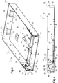
- the assistance device 1 is in the low position.
- the rear end or second end of the plate 3 remains substantially at the same height as the top of the rear wall 11.
- the front end or first end of the plate 3 is lowered.
- the front end of the plate 3 rests on the bottom 8.
- the front flap 4 is in the erected position.
- the front flap 4 projects from the frame 2.
- the front flap 4 has a lower end projecting towards the front and an upper end close to the front end of the plate 3.
- the side walls 9, 10 and the rear wall 11 comprise a substantially horizontal upper rim 12.
- Said upper rim 12 is continuous.
- Said upper rim 12 is obtained by folding.
- a weld can be provided in the corners.
- the assistance device 1 comprises a pair of covers 13, 14 arranged parallel to the side walls 9, 10.
- the covers 13, 14 also form the sides.
- the distance between the cover 13, 14 and the corresponding side wall 9, 10 is of the order of 6 to 12 mm.
- the distance between the cover 13, 14 and the corresponding side wall 9, 10 can be determined by washers or preferably by sheet metal spacers similar in shape to the shape of the covers 13, 14.
- the spacers reinforce the cover and the side wall . Openings are provided in the spacers to accommodate the parts arranged between the cover 13, 14 and the side wall 9, 10, in particular the arms below.
- the cover 13, 14 is fixed to the corresponding side wall 9, 10, for example by screws not shown.
- the covers 13 and 14 are arranged in the box 7.
- the covers 13 and 14 are disposed flush with the front end of the side walls 9, 10.
- the covers 13 and 14 extend between the bottom 8 and the upper edge 12
- the covers 13 and 14 rest on the bottom 8.
- the covers 13 and 14 extend from the front end of the box 7 towards the rear over a distance less than 50% of the distance between the mouth and the mouth. rear wall 11.
- the covers 13 and 14 have a rectangular envelope.
- Each cover 13, 14 is flat.
- Each cover 13, 14 is made from cut sheet metal.
- Each cover 13, 14 is provided with a notch 15 on a front edge. The notch 15 allows the articulation of the flap 4 to enter the box in the high position of the plate 3.
- Each cover 13, 14 is provided with a bore 16 adjacent to a rear edge of the cover.
- the bore 16 is close to the upper edge 13.
- the bore 16 serves to accommodate a pin 17 forming the articulation axis.
- the pin 17 comprises an enlarged base 18.
- the base 18 is fixed to the corresponding side wall 9, 10, for example by welding, on the outside of the side wall 9, 10.
- the pin 17 comprises a cylindrical body of revolution, cf. figure 10 .
- the body protrudes into the bore 16. The body can rest on the cover 13, 14.
- Each cover 13, 14 is provided with an opening 19 in an arc of a circle.
- the opening 19 has a concavity facing upwards.
- the opening 19 is distant from the front and rear ends of the cover 13, 14.
- the opening 19 is distant from the upper ends and lower cover 13, 14.
- the opening 19 extends over approximately 120 ° of angle.
- the opening 19 is centered on the bore 16.
- the opening 19 has a substantially vertical front end.
- the opening 19 has a front end adjacent to the upper edge 13.
- the opening 19 has a rear end, obscured by the plate 3 on the figure 1 , close to the bottom 8 and to the rear end of the cover 13, 14.
- the lower zone of the opening 19 is located vertically to the bore 16.
- Each cover 13, 14 is provided with an opening 20 in the form of an arc of a slide.
- the opening 20 has a concavity facing downwards.
- the opening 20 is distant from the front and rear ends of the cover 13, 14.
- the opening 20 is distant from the upper and lower ends of the cover 13, 14.
- the opening 20 extends over approximately 60 ° of angle.
- the opening 20 is centered on a geometric point located in the cover 13, 14.
- the opening 20 has a substantially vertical front end.
- the opening 20 has a front end close to the bottom 8 and the front end of the cover 13, 14.
- the opening 20 has a rear end close to the upper edge 13 and the front end of the opening 19.
- the opening 20 has a rear end close to the upper edge 13 and the front end of the opening 19. lower zone of the opening 19 is located vertically to the notch 15.
- the assistance device 1 is in the high position.
- the rear end of the plate 3 remains substantially at the same height as the top of the rear wall 11.
- the plate 3 is substantially horizontal.
- the front flap 4 is substantially vertical.
- the front flap 4 is in the retracted position.
- the front flap 4 is flush with the mouth of the frame 2.
- the lower end of the front flap 4 is in contact with or in the immediate vicinity of the front end of the bottom 8.
- the front flap 4 comprises small sides in contact or in the immediate vicinity from the front end of the side walls 9, 10.
- the upper end of the front flap 4 is close to the front end of the plate 3.
- the upper end of the front flap 4 is hinged to the front end of the plate 3.
- the tray 3 can include a frame and a top plate.
- the plate 3 is articulated around a horizontal axis adjacent to the rear wall 11 and located under the plate 3.
- the plate 3 comprises a substantially rectangular main surface with elongated parallel notches allowing the covers 13 and 14.
- the plate 3 comprises a rim 21 directed upwards.
- the rim 21 is peripheral to the main surface.
- the rim 21 has a constant of a few centimeters, for example 1 to 4 cm, allowing the plate 3 to receive a coating, for example stone slabs, a parquet, laminate, flexible synthetic covering, etc.
- the plate 3 can be made of sheet steel with a thickness of between 1 and 4 mm, preferably between 2 and 3.5 mm.
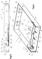
- the figure 3 shows the assistance device 1 in the absence of a platform.
- the assistance device 1 is in the high position.
- the assistance device 1 comprises a drive assembly 6 visible here.
- the drive assembly 6 includes a ram 61, a movable carriage 62, and a pair of arms 63.
- the ram 61 drives the movable carriage 62.
- the movable carriage 62 drives the arms 63.
- the ram 61 and the movable carriage 62 are arranged between the bottom 7 and the plate 3.
- the jack 61 is linear.
- the actuator 61 is preferably electric. However, the variant with a mechanical jack actuated manually, for example by crank, is possible.
- the jack 61 is parallel to the bottom 7.
- the jack 61 is parallel to the side walls 9, 10.
- the jack 61 comprises a stationary end directed towards the rear of the frame and a movable end directed towards the front of the frame, ie the mouth.
- the stationary end of the jack 61 is fixed to the bottom 8.
- the movable end of the jack 61 is fixed to the carriage 62, for example in the vicinity of the front edge of the carriage 62.
- the jack 61 is controlled by a pilot, not shown. The driver can be fitted with current detection.
- the movable end of the jack 61 and the carriage 62 are movable in horizontal translation between a front position, cf. figures 3, 4 & 9 , and a rear position, cf. figures 5 to 8 .
- the front position determines a high position of the plate 3.
- the rear position determines a low position of the plate 3.
- the carriage 62 rests on slides 81 mounted on the bottom 8.
- the slides 81 are horizontal.
- the slides 81 are parallel.
- the slides are four in number.
- Two or three slide embodiments are provided.
- the slides 81 can be in the form of a metal profile with a smooth and hard upper sliding surface.
- the carriage 62 is provided with two runners per slide.
- the pads arranged under the carriage 62 are not visible.
- the pads can be made of synthetic material with a low coefficient of friction, for example based on PTFE.
- the carriage 62 has a generally rectangular shape.
- the length of the carriage 62 is oriented between the side walls 9, 10, parallel to the rear wall 11.
- the width of the carriage 62 is oriented parallel to the side walls 9, 10. The length is greater than the width.
- the carriage 62 comprises a frame of cut and folded sheet metal.
- the frame has a rectangular bottom and longitudinal and side edges.
- the frame of the trolley is made of sheet steel with a thickness of between 1 and 4 mm, preferably 2 to 3.5 mm.
- the longitudinal and lateral edges are substantially vertical.
- the longitudinal and side edges are folded upwards.
- the longitudinal and lateral edges extend to a height of 1 to 4 centimeters.
- the rear longitudinal edge comprises an opening through which the cylinder 61 passes.
- the movable end of the jack 61 is fixed to the bottom of the frame 2 in the vicinity of the front longitudinal edge, ensuring stability of the carriage. Depending on the diameter of the cylinder, the opening can also extend into the bottom to reduce the overall height.
- the front longitudinal edge comprises a plurality of cutouts, here four, accommodating, in the lower position of the plate 3, profiles forming beams on the underside of the plate 3. One cutout is provided for each profile.
- the front longitudinal edge comprises end regions adjacent to the side edges and capable of resting on the side edges. The end regions form pushers 67 for the arms 63. The pushers 67 are, here, vertical.
- the carriage 62 is symmetrical with respect to a plane parallel to the side walls 9, 10.
- the frame 2 comprises at least one mechanical stop 82 limiting the travel of the carriage, the arrival at the stop causing a current draw from the electric actuator detected by the pilot of the actuator 61.
- four mechanical stops 82 are arranged on the bottom 8.
- Each mechanical stop 82 is mounted at the end of a slide 81, one on the front side, the other on the rear side.
- the frame 2 comprises two pairs of vertical plates 22, 23.
- Each plate 22, 23 is in the form of a flat rectangular part, for example made of sheet metal.
- Each plate 22, 23 rests on the bottom 8 by a small side.
- Each plate 22, 23 is in contact with the rear wall 11 by a large side or song.
- the plates 22, 23 can be welded to the bottom 8 and / or to the rear wall 11.
- a horizontal axis bore is provided in an upper zone of each plate 22, 23.
- the frame 2 comprises a pivot axis segment. 24 for each pair of plates 22, 23. Each end of a pivot pin segment 24 projects into the bore of a plate.
- Each pivot pin segment 24 can be held in the bores by circlips, snap rings or internally toothed washers.
- Each axis segment pivot 24 is supported by a pair of plates.
- the pivot pin segments 24 are adjacent to the upper end of the rear wall 11.
- the pivot pin segments 24 are spaced apart to provide good stability.
- the plate 3 comes to rest on the pivot axis segments 24.
- the plate 3 can be secured to the pivot axis segments 24 by flanges.
- the plate 3 is mounted to pivot relative to the frame 2. The pivoting takes place over a limited angle, for example less than 15 °, so that the gap between the rear end of the plate 3 and the rear wall 11 remains negligible. for example less than 3 mm.
- the arms 63 are symmetrical. Each arm 63 is disposed between the side wall 9, 10 and the neighboring cover 13, 14. Thus, the arm is housed in one side of the frame 2. Each arm 63 is articulated on a pin 17 forming a tilting axis. The pin 17 is supported by the side wall 9, 10 and the cover 13, 14. The pin 17 is disposed in the upper region of the cover 13, 14. The pin 17 is disposed in the rear region of the cover 13, 14. The pins 17 are coaxial. The pins 17 are perpendicular to the side walls 9 and 10. The pins 17 are horizontal.
- Each arm 63 has a generally triangular shape or a portion of a circle.
- Each arm 63 comprises a planar body 63a.
- the body 63a is made from a cut sheet metal blank. Folding or stamping is avoided.
- the body 63a can be between 1 and 4 mm thick.
- the body 63a is articulated on the pin 17.
- the pin 17 is arranged in the vicinity of a vertex of the triangle, the base of the triangle being closer to the bottom 8. Said vertex has an angle of between 50 and 70 °.
- Each arm 63 comprises a first finger 65 receiving the thrust of the pusher 67 of the carriage.
- the first finger 65 comprises a base 65a and a pin 65b.
- the pin 65b passes through a bore in the body of the arm 63.
- the base 65a is welded to said body on the side opposite to the projection of the pin 65b.
- the base 65a has the shape of a solid disc.
- the base 65a has a thickness of between 1 and 3 mm.
- the pin 65b has a cylindrical shape of revolution.
- the pin 65b can include a bearing to reduce friction.
- the pin 65b may have a diameter of between 8 and 20 mm, preferably between 8 and 12 mm.
- the first finger 65 is disposed in the vicinity of a second vertex of the triangle.
- Each arm 63 comprises a second finger 66 supporting the plate 3 in the vicinity of its first end.
- the second finger 66 receives the thrust of the plate 3 and drives the pivoting of the plate 3.
- the second finger 66 comprises a base 66a and a pin 66b.
- the pin 66b passes through a bore in the body of the arm 63.
- the base 66a is welded to said body on the side opposite the projection of the pin 66b.
- the base 66a has the shape of a solid disc.
- the base 66a has a thickness of between 1 and 3 mm.
- the pin 66b has a cylindrical shape of revolution.
- the pin 66b can include a bearing to reduce friction.
- the pin 66b can have a diameter of between 8 and 20 mm, preferably between 12 and 16 mm.
- the second finger 66 is disposed in the vicinity of a third vertex of the triangle.
- the angle between a straight line passing through the pin 17 and the pusher 67 of the carriage, corresponding to the contact surface of the first finger 65, and a straight line passing through the pin 17 and the contact surface of the second finger 66 with the plate 3 is between 50 and 70 °, preferably between 55 and 65 °.
- the ends of the pins 65b and 66b opposite the bases 65a and 66a are connected together by a spacer.
- the thickness of the body of the arms may be reduced.
- the first finger 65 and the second finger 66 have parallel axes.
- the first finger 65 and the second finger 66 pass through the opening 19.
- the first finger 65 and the second finger 66 project into the space located between the bottom 8 and the plate 3.
- the first finger 65 and the second finger 66 are arranged at different distances from the pins 17.
- An amplifier is thus formed.
- the distance pin 17 - first finger 65 is less than the distance pin 17 - second finger 66.
- the vertical stroke of the front end of the plate 3 is greater than the horizontal stroke of the jack, for example by 4%.
- the opening 19 has a recess 31 substantially in its middle.
- the opening 19 comprises a first portion for the stroke of the first finger 65 and a second portion for the stroke of the second finger 66.
- the portions are contiguous forming a single opening.
- the first and second portions may be separate, resulting in two openings, for example for a higher amplifying effect.
- the first finger 65 is located at the rear end of the opening 19 and the second finger 66 is located at the rear end of the second portion in the vicinity of the step 31.
- the first finger 65 and the second finger 66 are substantially at the same distance from the bottom 8.
- the first finger 65 is located at the front end of the first portion of the opening 19 in the vicinity of the recess 31 and the second finger 66 is located at the front end of the opening 19 in the vicinity of the edge upper cover 13, 14.
- the first finger 65 and the second finger 66 define a straight line inclined relative to the horizontal by approximately 50 to 70 °.
- the vertical travel of the first finger 65 on the pusher 67 of the carriage is small.
- the pusher 67 of the carriage may have a small vertical dimension.
- the straight line passing through the pin 17 and the point of contact between the second finger 66 and the plate 3 pivots by the same angle during the movement of the arm.
- the horizontal travel of the second finger 66 on the plate 3 is small, of the order of 50% of the radius between the pin 17 and the contact surface of the second finger 66 with the plate 3.
- pivoting arms are replaced by sliding rods.
- the shutter 4 is articulated on the front end of the plate 3.
- a hinge 46 with a substantially horizontal axis is provided.
- the hinge 46 is fixed on the one hand to the flap 4 near an upper edge of said flap 4, and on the other hand, to the plate 3.
- the fixing 3 can be made to the rim 21.
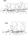
- the assistance device 1 comprises a mechanism 40 for deploying the shutter 4.
- the mechanism 40 indexes the position of the shutter 4 on the position of the plate 3.
- the mechanism 40 closes the shutter 4 in position. top of the plate 3 and the deployment of the shutter 4 in the lower position of the plate 3.
- the term “mechanism” is understood here to mean a member without an electric actuator.
- the mechanism 40 can optionally be provided with a sensor. In the mode shown, the mechanism 40 does not have a sensor.
- the mechanism 40 provides an amplified displacement at the start of the descent of the plate 3.
- a given vertical displacement of the front end of the plate 3 requires at least equal vertical displacement of the lower edge of the shutter 4 to avoid coming into contact. with the ground too early.
- the shutter 4 being articulated at its upper edge, the required angular pivoting is high, the vertical displacement following a law H x (1-cos ⁇ ⁇ , with ⁇ the angle of the shutter with respect to the vertical and H the height of the shutter
- the mechanism 40 provides play at the end of the descent of the plate 3. In fact, it is desirable for the shutter 4 to come into contact with the ground and be able to adapt to soils of different levels.
- the required angular pivoting is low, the vertical displacement according to the same law but ⁇ being close to 90 °.
- the mechanism 40 comprises a pair of symmetrical connecting rods 42, one connecting rod per side of the frame 2.
- Each connecting rod 42 is an elongated part.
- Each connecting rod 42 can be formed by a blank of cut sheet metal and arranged in one or more thicknesses.
- Each connecting rod 42 comprises a front end articulated to the flap 4, a rear end slidably mounted relative to the plate 3 and a central portion slidably mounted relative to the frame 2.
- the front end of the connecting rod 42 is linked to an articulation 43 remote from the top edge and the bottom edge of said flap 4.
- the articulation 43 is mounted substantially midway between the top edge and the bottom edge of said flap 4. More generally, the articulation 43 is mounted between 1/3 and 2/3 of the height of the shutter 4.
- the stroke of the connecting rod 42 is less than the stroke of the bottom edge of the shutter 4.
- the articulation 43 is arranged on the rear face of the shutter 4, forming the lower face in the deployed position of the shutter. 4.
- the notch 15 of the cover 13, 14 forms a housing for the articulation 43 in the high position of the plate 3.
- the rear end of the connecting rod 42 is linked to a first slide 44 slidably mounted in a linear slide 32 of the plate 3.
- the connecting rod 42 can move in rotation and in translation relative to the plate 3.
- the translational stroke is limited by the length of the linear slide 32.
- the linear slide 32 is substantially horizontal in the high position of the plate 3.
- the linear slide 32 is parallel to the plate 3.
- the linear slide 32 comprises an elongated flat in which is formed a rectilinear opening 33.
- the linear slide 32 may comprise a piece of sheet metal bent in a U symmetry with respect to a central plane, each branch of the U being provided with a rectilinear opening 33.
- the bottom of the U is fixed to the plate 3 on the underside, for example by welding. Each branch of the U is directed downwards.
- Each branch of the U is parallel to the covers 13, 14.
- a chamfer 34 is provided in each branch of the U to make it possible to reach the low position of the plate illustrated on the figure. figure 7 .
- the lower edge of the branches of the U is likely to come to rest on the bottom 8.
- Each slit 35 is formed between a branch of the U and the bottom in the fold zone. Each slit 35 is of a length greater than the length of the rectilinear opening 33. Each slit 35 extends in front of and behind the rectilinear opening 33.
- the slits 35 promote the folding of the branches of the U from a Flat sheet blank while reducing the risk of deformation in the vicinity of rectilinear openings 33.
- said sheet is of the same thickness as the other main parts.
- the slide 44 is in the form of a pin.
- the slider 44 comprises a base fixed to the connecting rod 42, a cylindrical body of revolution arranged in the rectilinear opening 33 and a head with a diameter greater than the diameter of the body placed on the side of the body opposite to the connecting rod 42.
- the slide 44 may be symmetrical with respect to the connecting rod and include two bodies and two heads to cooperate with the two rectilinear openings 33.
- the body may be provided with a bearing so that the slide 44 rolls on the edges of the rectilinear openings 33.
- the rear end of the connecting rod 42 is thus pivoting relative to the plate 3.
- the rear end of the connecting rod 42 is sliding in translation along the length of the rectilinear openings 33.
- the linear slide 32 In the high position of the plate 3, the linear slide 32 is located above the opening 20.
- the linear slide 32 is located between the opening 19 and the mouth of the frame 2.
- the central portion of the connecting rod 42 is mounted to pivot and slide relative to the frame 2.
- the opening 20 forms a slide for this purpose.
- a slide 45 Between the opening 20 and the connecting rod 42 is mounted a slide 45.
- the slide 45 is in the form of a pin.
- the slider 45 comprises a base fixed to the connecting rod 42, a cylindrical body of revolution disposed in the opening 20 and a head of diameter greater than the diameter of the body disposed on the side of the body opposite to the connecting rod 42.
- the body can be provided with 'a level of so that the slide 45 rolls on the edge of the opening 20.
- the central portion of the connecting rod 42 is thus pivoting relative to the frame 2 and sliding in translation on the opening 20.
- the slide 45 is located at the upper end of the opening 20.
- the slide 44 is located substantially at the rear of the linear slide 32.
- the connecting rod 42 has an angle of the order of 10 to 30 ° from the horizontal.
- the shutter 4 is closed, i.e. substantially vertical.
- the rear end of the connecting rod 42 goes down as well as the front end, the slide 45 to follow said descent is forced to move forward in the opening 20 which causes the connecting rod 42 towards the front, in particular towards the front of the linear slide 32.
- the amplification of the horizontal movement of the connecting rod 42 towards the front, at this stage, is obtained, in particular, by the inclination of the upper end of the opening 20.
- the amplification of the horizontal movement of the lower end of the shutter 4 is also obtained by the positioning of the articulation on the shutter 4. The converse applies at the end of the upward movement of the plate. 3.
- the slide 45 is located at the lower end of the opening 20.
- the slide 44 is located substantially at the front of the linear slide 32.
- the connecting rod 42 is substantially horizontal.
- the shutter 4 is open, i.e. protruding towards the front by its lower end with an inclination depending on the configuration of the ground.
- the rear end of the connecting rod 42 descends.
- the front end of the connecting rod 42 descends more slowly because the pivoting of the shutter 4 forwards decreases the amplitude of this movement.
- the slide 45 is located towards the front end of the opening 20, on a portion close to the vertical. The horizontal movement of the connecting rod 42 forwards is therefore reduced compared to the vertical movement of the plate 3.
- Said portion close to the vertical of the opening 20 offers the shutter 4 a large clearance to adapt to different soils without particular setting.
- the shutter 4 can remain resting on the ground.
- the horizontal movement of the connecting rod 42 is very small due to the inclination of the front end of the opening 20.
- the operation of the shutter is safe, reliable and easy while being driven by the operation of the plate.
- the assistance device is reliable and robust while being able to adapt to various configurations of existing constructions.
Landscapes
- Engineering & Computer Science (AREA)
- Architecture (AREA)
- Civil Engineering (AREA)
- Structural Engineering (AREA)
- Auxiliary Methods And Devices For Loading And Unloading (AREA)
- Bending Of Plates, Rods, And Pipes (AREA)
- Pallets (AREA)
Applications Claiming Priority (2)
| Application Number | Priority Date | Filing Date | Title |
|---|---|---|---|
| FR1561689A FR3044271B1 (fr) | 2015-12-01 | 2015-12-01 | Dispositif d'assistance au franchissement d'un obstacle par un vehicule |
| PCT/FR2016/053149 WO2017093663A1 (fr) | 2015-12-01 | 2016-11-30 | Dispositif d'assistance au franchissement d'un obstacle par un vehicule |
Publications (2)
| Publication Number | Publication Date |
|---|---|
| EP3384102A1 EP3384102A1 (fr) | 2018-10-10 |
| EP3384102B1 true EP3384102B1 (fr) | 2021-07-07 |
Family
ID=55135425
Family Applications (1)
| Application Number | Title | Priority Date | Filing Date |
|---|---|---|---|
| EP16813094.6A Active EP3384102B1 (fr) | 2015-12-01 | 2016-11-30 | Dispositif d'assistance au franchissement d'un obstacle par un véhicule |
Country Status (7)
| Country | Link |
|---|---|
| US (1) | US10501941B2 (es) |
| EP (1) | EP3384102B1 (es) |
| CA (1) | CA3006887A1 (es) |
| ES (1) | ES2893612T3 (es) |
| FR (1) | FR3044271B1 (es) |
| WO (1) | WO2017093663A1 (es) |
| ZA (1) | ZA201804160B (es) |
Families Citing this family (2)
| Publication number | Priority date | Publication date | Assignee | Title |
|---|---|---|---|---|
| FR3116431B1 (fr) * | 2020-11-26 | 2023-02-10 | Mydl | Dispositif d’assistance au franchissement d’un obstacle |
| FR3117139B1 (fr) | 2020-12-09 | 2022-12-16 | Mydl | Dispositif d’assistance au franchissement d’un obstacle par un vehicule |
Citations (5)
| Publication number | Priority date | Publication date | Assignee | Title |
|---|---|---|---|---|
| FR2836403B1 (fr) * | 2002-02-22 | 2004-07-02 | Dimeco Alipresse | Dispositif de frappe pour machine a poinconner et machine a poinconner equipe de ce dispositif |
| FR3015432A1 (fr) * | 2013-12-19 | 2015-06-26 | Airbus Operations Sas | Ensemble pour aeronef comprenant un moteur a hauteur reglable et procede de commande de l'aeronef |
| FR3043032A1 (fr) * | 2015-10-28 | 2017-05-05 | Renault Sas | Marchepied escamotable pour vehicule automobile. |
| FR3051027A1 (fr) * | 2016-05-03 | 2017-11-10 | Zodiac Hydraulics | Etage de pilotage de servovalve, pouvant servir de premier etage dans une servovalve a deux etages. |
| FR3078278A1 (fr) * | 2018-02-26 | 2019-08-30 | Addup | Dispositif de fabrication additive |
Family Cites Families (11)
| Publication number | Priority date | Publication date | Assignee | Title |
|---|---|---|---|---|
| FR2947224B1 (fr) * | 2009-06-25 | 2011-06-03 | Myd L | Dispositif d'aide au franchissement d'une marche pour un vehicule a roues |
| GB201109698D0 (en) * | 2011-06-10 | 2011-07-27 | Humble Christopher | System for facilitating access to and from a building |
| FR3012832B1 (fr) * | 2013-11-04 | 2015-12-04 | Myd L | Dispositif d'assistance pour personne a mobilite reduite |
| FR3016149B1 (fr) * | 2014-01-08 | 2016-01-08 | Myd L | Disposition d'assistance au franchissement d'un obstacle par un vehicule |
| US8832893B1 (en) * | 2014-01-10 | 2014-09-16 | Lift-U, Division Of Hogan Mfg., Inc. | Operable ramp |
| US8887337B1 (en) * | 2014-03-05 | 2014-11-18 | Lift-U, Division Of Hogan Mfg., Inc. | Operable ramp |
| US8918939B1 (en) * | 2014-06-12 | 2014-12-30 | Lift-U, Division Of Hogan, Mfg., Inc. | Operable ramp |
| US9580910B1 (en) * | 2015-09-11 | 2017-02-28 | Lift-U, Division Of Hogan Mfg. Inc. | Operable ramp |
| US9587404B1 (en) * | 2016-04-19 | 2017-03-07 | Lift-U, Division Of Hogan Mfg., Inc. | Operable ramp |
| US9708815B1 (en) * | 2017-02-03 | 2017-07-18 | Lift-U, Division Of Hogan Mfg., Inc. | Operable ramp |
| US9963883B1 (en) * | 2017-02-03 | 2018-05-08 | Lift-U, Division Of Hogan Mfg., Inc. | Operable ramp |
-
2015
- 2015-12-01 FR FR1561689A patent/FR3044271B1/fr active Active
-
2016
- 2016-11-30 CA CA3006887A patent/CA3006887A1/fr active Pending
- 2016-11-30 ES ES16813094T patent/ES2893612T3/es active Active
- 2016-11-30 EP EP16813094.6A patent/EP3384102B1/fr active Active
- 2016-11-30 WO PCT/FR2016/053149 patent/WO2017093663A1/fr active Application Filing
- 2016-11-30 US US15/780,255 patent/US10501941B2/en active Active
-
2018
- 2018-06-21 ZA ZA2018/04160A patent/ZA201804160B/en unknown
Patent Citations (5)
| Publication number | Priority date | Publication date | Assignee | Title |
|---|---|---|---|---|
| FR2836403B1 (fr) * | 2002-02-22 | 2004-07-02 | Dimeco Alipresse | Dispositif de frappe pour machine a poinconner et machine a poinconner equipe de ce dispositif |
| FR3015432A1 (fr) * | 2013-12-19 | 2015-06-26 | Airbus Operations Sas | Ensemble pour aeronef comprenant un moteur a hauteur reglable et procede de commande de l'aeronef |
| FR3043032A1 (fr) * | 2015-10-28 | 2017-05-05 | Renault Sas | Marchepied escamotable pour vehicule automobile. |
| FR3051027A1 (fr) * | 2016-05-03 | 2017-11-10 | Zodiac Hydraulics | Etage de pilotage de servovalve, pouvant servir de premier etage dans une servovalve a deux etages. |
| FR3078278A1 (fr) * | 2018-02-26 | 2019-08-30 | Addup | Dispositif de fabrication additive |
Also Published As
| Publication number | Publication date |
|---|---|
| ZA201804160B (en) | 2020-06-24 |
| FR3044271A1 (fr) | 2017-06-02 |
| FR3044271B1 (fr) | 2018-01-12 |
| US10501941B2 (en) | 2019-12-10 |
| EP3384102A1 (fr) | 2018-10-10 |
| CA3006887A1 (fr) | 2017-06-08 |
| US20180347202A1 (en) | 2018-12-06 |
| WO2017093663A1 (fr) | 2017-06-08 |
| ES2893612T3 (es) | 2022-02-09 |
Similar Documents
| Publication | Publication Date | Title |
|---|---|---|
| EP3134591B1 (fr) | Dispositif d'assistance au franchissement d'un obstacle par un véhicule | |
| EP3384103B1 (fr) | Dispositif d'assistance au franchissement d'un obstacle par un véhicule | |
| EP3066274B1 (fr) | Dispositif d'assistance pour personne a mobilité réduite | |
| EP3384102B1 (fr) | Dispositif d'assistance au franchissement d'un obstacle par un véhicule | |
| EP2352889B1 (fr) | Dispositif de couverture pour bassin | |
| EP0759005B1 (fr) | Dispositif de marches elevatrices | |
| WO2022123173A1 (fr) | Dispositif d'assistance au franchissement d'un obstacle par un vehicule | |
| FR2916219A1 (fr) | Abri en particulier pour piscine. | |
| EP2843144B1 (fr) | Cloison modulaire | |
| EP4251113A1 (fr) | Dispositif d'assistance au franchissement d'un obstacle | |
| FR3020650A1 (fr) | Abri de piscine a modules telescopiques comprenant un systeme de verrouillage des modules | |
| FR2891559A1 (fr) | Installation de cloison coulissante | |
| FR2996184A1 (fr) | Construction habitable industrialisee deplacable sur roues |
Legal Events
| Date | Code | Title | Description |
|---|---|---|---|
| STAA | Information on the status of an ep patent application or granted ep patent |
Free format text: STATUS: UNKNOWN |
|
| STAA | Information on the status of an ep patent application or granted ep patent |
Free format text: STATUS: THE INTERNATIONAL PUBLICATION HAS BEEN MADE |
|
| PUAI | Public reference made under article 153(3) epc to a published international application that has entered the european phase |
Free format text: ORIGINAL CODE: 0009012 |
|
| STAA | Information on the status of an ep patent application or granted ep patent |
Free format text: STATUS: REQUEST FOR EXAMINATION WAS MADE |
|
| 17P | Request for examination filed |
Effective date: 20180601 |
|
| AK | Designated contracting states |
Kind code of ref document: A1 Designated state(s): AL AT BE BG CH CY CZ DE DK EE ES FI FR GB GR HR HU IE IS IT LI LT LU LV MC MK MT NL NO PL PT RO RS SE SI SK SM TR |
|
| AX | Request for extension of the european patent |
Extension state: BA ME |
|
| DAV | Request for validation of the european patent (deleted) | ||
| DAX | Request for extension of the european patent (deleted) | ||
| STAA | Information on the status of an ep patent application or granted ep patent |
Free format text: STATUS: EXAMINATION IS IN PROGRESS |
|
| 17Q | First examination report despatched |
Effective date: 20190627 |
|
| GRAP | Despatch of communication of intention to grant a patent |
Free format text: ORIGINAL CODE: EPIDOSNIGR1 |
|
| STAA | Information on the status of an ep patent application or granted ep patent |
Free format text: STATUS: GRANT OF PATENT IS INTENDED |
|
| INTG | Intention to grant announced |
Effective date: 20210129 |
|
| GRAS | Grant fee paid |
Free format text: ORIGINAL CODE: EPIDOSNIGR3 |
|
| GRAA | (expected) grant |
Free format text: ORIGINAL CODE: 0009210 |
|
| STAA | Information on the status of an ep patent application or granted ep patent |
Free format text: STATUS: THE PATENT HAS BEEN GRANTED |
|
| AK | Designated contracting states |
Kind code of ref document: B1 Designated state(s): AL AT BE BG CH CY CZ DE DK EE ES FI FR GB GR HR HU IE IS IT LI LT LU LV MC MK MT NL NO PL PT RO RS SE SI SK SM TR |
|
| REG | Reference to a national code |
Ref country code: GB Ref legal event code: FG4D Free format text: NOT ENGLISH |
|
| REG | Reference to a national code |
Ref country code: AT Ref legal event code: REF Ref document number: 1408733 Country of ref document: AT Kind code of ref document: T Effective date: 20210715 |
|
| REG | Reference to a national code |
Ref country code: DE Ref legal event code: R096 Ref document number: 602016060395 Country of ref document: DE |
|
| REG | Reference to a national code |
Ref country code: IE Ref legal event code: FG4D Free format text: LANGUAGE OF EP DOCUMENT: FRENCH |
|
| REG | Reference to a national code |
Ref country code: LT Ref legal event code: MG9D |
|
| REG | Reference to a national code |
Ref country code: NL Ref legal event code: MP Effective date: 20210707 |
|
| REG | Reference to a national code |
Ref country code: AT Ref legal event code: MK05 Ref document number: 1408733 Country of ref document: AT Kind code of ref document: T Effective date: 20210707 |
|
| PG25 | Lapsed in a contracting state [announced via postgrant information from national office to epo] |
Ref country code: LT Free format text: LAPSE BECAUSE OF FAILURE TO SUBMIT A TRANSLATION OF THE DESCRIPTION OR TO PAY THE FEE WITHIN THE PRESCRIBED TIME-LIMIT Effective date: 20210707 Ref country code: AT Free format text: LAPSE BECAUSE OF FAILURE TO SUBMIT A TRANSLATION OF THE DESCRIPTION OR TO PAY THE FEE WITHIN THE PRESCRIBED TIME-LIMIT Effective date: 20210707 Ref country code: BG Free format text: LAPSE BECAUSE OF FAILURE TO SUBMIT A TRANSLATION OF THE DESCRIPTION OR TO PAY THE FEE WITHIN THE PRESCRIBED TIME-LIMIT Effective date: 20211007 Ref country code: HR Free format text: LAPSE BECAUSE OF FAILURE TO SUBMIT A TRANSLATION OF THE DESCRIPTION OR TO PAY THE FEE WITHIN THE PRESCRIBED TIME-LIMIT Effective date: 20210707 Ref country code: FI Free format text: LAPSE BECAUSE OF FAILURE TO SUBMIT A TRANSLATION OF THE DESCRIPTION OR TO PAY THE FEE WITHIN THE PRESCRIBED TIME-LIMIT Effective date: 20210707 Ref country code: NL Free format text: LAPSE BECAUSE OF FAILURE TO SUBMIT A TRANSLATION OF THE DESCRIPTION OR TO PAY THE FEE WITHIN THE PRESCRIBED TIME-LIMIT Effective date: 20210707 Ref country code: PT Free format text: LAPSE BECAUSE OF FAILURE TO SUBMIT A TRANSLATION OF THE DESCRIPTION OR TO PAY THE FEE WITHIN THE PRESCRIBED TIME-LIMIT Effective date: 20211108 Ref country code: NO Free format text: LAPSE BECAUSE OF FAILURE TO SUBMIT A TRANSLATION OF THE DESCRIPTION OR TO PAY THE FEE WITHIN THE PRESCRIBED TIME-LIMIT Effective date: 20211007 Ref country code: SE Free format text: LAPSE BECAUSE OF FAILURE TO SUBMIT A TRANSLATION OF THE DESCRIPTION OR TO PAY THE FEE WITHIN THE PRESCRIBED TIME-LIMIT Effective date: 20210707 Ref country code: RS Free format text: LAPSE BECAUSE OF FAILURE TO SUBMIT A TRANSLATION OF THE DESCRIPTION OR TO PAY THE FEE WITHIN THE PRESCRIBED TIME-LIMIT Effective date: 20210707 |
|
| REG | Reference to a national code |
Ref country code: ES Ref legal event code: FG2A Ref document number: 2893612 Country of ref document: ES Kind code of ref document: T3 Effective date: 20220209 |
|
| PG25 | Lapsed in a contracting state [announced via postgrant information from national office to epo] |
Ref country code: PL Free format text: LAPSE BECAUSE OF FAILURE TO SUBMIT A TRANSLATION OF THE DESCRIPTION OR TO PAY THE FEE WITHIN THE PRESCRIBED TIME-LIMIT Effective date: 20210707 Ref country code: LV Free format text: LAPSE BECAUSE OF FAILURE TO SUBMIT A TRANSLATION OF THE DESCRIPTION OR TO PAY THE FEE WITHIN THE PRESCRIBED TIME-LIMIT Effective date: 20210707 Ref country code: GR Free format text: LAPSE BECAUSE OF FAILURE TO SUBMIT A TRANSLATION OF THE DESCRIPTION OR TO PAY THE FEE WITHIN THE PRESCRIBED TIME-LIMIT Effective date: 20211008 |
|
| REG | Reference to a national code |
Ref country code: DE Ref legal event code: R097 Ref document number: 602016060395 Country of ref document: DE |
|
| PG25 | Lapsed in a contracting state [announced via postgrant information from national office to epo] |
Ref country code: DK Free format text: LAPSE BECAUSE OF FAILURE TO SUBMIT A TRANSLATION OF THE DESCRIPTION OR TO PAY THE FEE WITHIN THE PRESCRIBED TIME-LIMIT Effective date: 20210707 |
|
| PLBE | No opposition filed within time limit |
Free format text: ORIGINAL CODE: 0009261 |
|
| STAA | Information on the status of an ep patent application or granted ep patent |
Free format text: STATUS: NO OPPOSITION FILED WITHIN TIME LIMIT |
|
| PG25 | Lapsed in a contracting state [announced via postgrant information from national office to epo] |
Ref country code: SM Free format text: LAPSE BECAUSE OF FAILURE TO SUBMIT A TRANSLATION OF THE DESCRIPTION OR TO PAY THE FEE WITHIN THE PRESCRIBED TIME-LIMIT Effective date: 20210707 Ref country code: SK Free format text: LAPSE BECAUSE OF FAILURE TO SUBMIT A TRANSLATION OF THE DESCRIPTION OR TO PAY THE FEE WITHIN THE PRESCRIBED TIME-LIMIT Effective date: 20210707 Ref country code: RO Free format text: LAPSE BECAUSE OF FAILURE TO SUBMIT A TRANSLATION OF THE DESCRIPTION OR TO PAY THE FEE WITHIN THE PRESCRIBED TIME-LIMIT Effective date: 20210707 Ref country code: EE Free format text: LAPSE BECAUSE OF FAILURE TO SUBMIT A TRANSLATION OF THE DESCRIPTION OR TO PAY THE FEE WITHIN THE PRESCRIBED TIME-LIMIT Effective date: 20210707 Ref country code: CZ Free format text: LAPSE BECAUSE OF FAILURE TO SUBMIT A TRANSLATION OF THE DESCRIPTION OR TO PAY THE FEE WITHIN THE PRESCRIBED TIME-LIMIT Effective date: 20210707 Ref country code: AL Free format text: LAPSE BECAUSE OF FAILURE TO SUBMIT A TRANSLATION OF THE DESCRIPTION OR TO PAY THE FEE WITHIN THE PRESCRIBED TIME-LIMIT Effective date: 20210707 |
|
| 26N | No opposition filed |
Effective date: 20220408 |
|
| PG25 | Lapsed in a contracting state [announced via postgrant information from national office to epo] |
Ref country code: MC Free format text: LAPSE BECAUSE OF FAILURE TO SUBMIT A TRANSLATION OF THE DESCRIPTION OR TO PAY THE FEE WITHIN THE PRESCRIBED TIME-LIMIT Effective date: 20210707 |
|
| REG | Reference to a national code |
Ref country code: CH Ref legal event code: PL |
|
| GBPC | Gb: european patent ceased through non-payment of renewal fee |
Effective date: 20211130 |
|
| PG25 | Lapsed in a contracting state [announced via postgrant information from national office to epo] |
Ref country code: LU Free format text: LAPSE BECAUSE OF NON-PAYMENT OF DUE FEES Effective date: 20211130 Ref country code: BE Free format text: LAPSE BECAUSE OF NON-PAYMENT OF DUE FEES Effective date: 20211130 |
|
| REG | Reference to a national code |
Ref country code: BE Ref legal event code: MM Effective date: 20211130 |
|
| PG25 | Lapsed in a contracting state [announced via postgrant information from national office to epo] |
Ref country code: LI Free format text: LAPSE BECAUSE OF NON-PAYMENT OF DUE FEES Effective date: 20211130 Ref country code: CH Free format text: LAPSE BECAUSE OF NON-PAYMENT OF DUE FEES Effective date: 20211130 |
|
| PG25 | Lapsed in a contracting state [announced via postgrant information from national office to epo] |
Ref country code: IE Free format text: LAPSE BECAUSE OF NON-PAYMENT OF DUE FEES Effective date: 20211130 Ref country code: GB Free format text: LAPSE BECAUSE OF NON-PAYMENT OF DUE FEES Effective date: 20211130 |
|
| PGFP | Annual fee paid to national office [announced via postgrant information from national office to epo] |
Ref country code: IT Payment date: 20221124 Year of fee payment: 7 Ref country code: DE Payment date: 20221123 Year of fee payment: 7 |
|
| PGFP | Annual fee paid to national office [announced via postgrant information from national office to epo] |
Ref country code: ES Payment date: 20230125 Year of fee payment: 7 |
|
| PG25 | Lapsed in a contracting state [announced via postgrant information from national office to epo] |
Ref country code: HU Free format text: LAPSE BECAUSE OF FAILURE TO SUBMIT A TRANSLATION OF THE DESCRIPTION OR TO PAY THE FEE WITHIN THE PRESCRIBED TIME-LIMIT; INVALID AB INITIO Effective date: 20161130 |
|
| PG25 | Lapsed in a contracting state [announced via postgrant information from national office to epo] |
Ref country code: CY Free format text: LAPSE BECAUSE OF FAILURE TO SUBMIT A TRANSLATION OF THE DESCRIPTION OR TO PAY THE FEE WITHIN THE PRESCRIBED TIME-LIMIT Effective date: 20210707 |
|
| PG25 | Lapsed in a contracting state [announced via postgrant information from national office to epo] |
Ref country code: MK Free format text: LAPSE BECAUSE OF FAILURE TO SUBMIT A TRANSLATION OF THE DESCRIPTION OR TO PAY THE FEE WITHIN THE PRESCRIBED TIME-LIMIT Effective date: 20210707 |
|
| PGFP | Annual fee paid to national office [announced via postgrant information from national office to epo] |
Ref country code: FR Payment date: 20240205 Year of fee payment: 9 |
|
| REG | Reference to a national code |
Ref country code: DE Ref legal event code: R119 Ref document number: 602016060395 Country of ref document: DE |
|
| PG25 | Lapsed in a contracting state [announced via postgrant information from national office to epo] |
Ref country code: TR Free format text: LAPSE BECAUSE OF FAILURE TO SUBMIT A TRANSLATION OF THE DESCRIPTION OR TO PAY THE FEE WITHIN THE PRESCRIBED TIME-LIMIT Effective date: 20210707 |