EP3383463B1 - Device for treating ataxic breathing - Google Patents
Device for treating ataxic breathing Download PDFInfo
- Publication number
- EP3383463B1 EP3383463B1 EP16802008.9A EP16802008A EP3383463B1 EP 3383463 B1 EP3383463 B1 EP 3383463B1 EP 16802008 A EP16802008 A EP 16802008A EP 3383463 B1 EP3383463 B1 EP 3383463B1
- Authority
- EP
- European Patent Office
- Prior art keywords
- breathing
- patient
- ataxic
- time
- flow
- Prior art date
- Legal status (The legal status is an assumption and is not a legal conclusion. Google has not performed a legal analysis and makes no representation as to the accuracy of the status listed.)
- Active
Links
- 230000029058 respiratory gaseous exchange Effects 0.000 title claims description 231
- 206010003591 Ataxia Diseases 0.000 title claims description 60
- 230000001977 ataxic effect Effects 0.000 title claims description 60
- 238000009423 ventilation Methods 0.000 claims description 36
- 230000002269 spontaneous effect Effects 0.000 claims description 20
- 230000035565 breathing frequency Effects 0.000 claims description 10
- 238000012544 monitoring process Methods 0.000 claims description 9
- 239000007789 gas Substances 0.000 description 62
- 238000000034 method Methods 0.000 description 23
- 238000002560 therapeutic procedure Methods 0.000 description 8
- 230000001788 irregular Effects 0.000 description 6
- 238000011156 evaluation Methods 0.000 description 5
- 238000011282 treatment Methods 0.000 description 5
- CURLTUGMZLYLDI-UHFFFAOYSA-N Carbon dioxide Chemical compound O=C=O CURLTUGMZLYLDI-UHFFFAOYSA-N 0.000 description 4
- 229910002092 carbon dioxide Inorganic materials 0.000 description 4
- 208000037265 diseases, disorders, signs and symptoms Diseases 0.000 description 4
- 230000007246 mechanism Effects 0.000 description 4
- 238000012545 processing Methods 0.000 description 4
- 238000002644 respiratory therapy Methods 0.000 description 4
- 230000000694 effects Effects 0.000 description 3
- 201000002859 sleep apnea Diseases 0.000 description 3
- 230000001360 synchronised effect Effects 0.000 description 3
- 238000004590 computer program Methods 0.000 description 2
- 238000010586 diagram Methods 0.000 description 2
- 208000035475 disorder Diseases 0.000 description 2
- 230000008030 elimination Effects 0.000 description 2
- 238000003379 elimination reaction Methods 0.000 description 2
- 238000005399 mechanical ventilation Methods 0.000 description 2
- 239000000203 mixture Substances 0.000 description 2
- 238000012806 monitoring device Methods 0.000 description 2
- 230000000926 neurological effect Effects 0.000 description 2
- 230000003287 optical effect Effects 0.000 description 2
- 230000033764 rhythmic process Effects 0.000 description 2
- 230000002159 abnormal effect Effects 0.000 description 1
- QVGXLLKOCUKJST-UHFFFAOYSA-N atomic oxygen Chemical compound [O] QVGXLLKOCUKJST-UHFFFAOYSA-N 0.000 description 1
- 230000006399 behavior Effects 0.000 description 1
- 239000008280 blood Substances 0.000 description 1
- 210000004369 blood Anatomy 0.000 description 1
- 210000004556 brain Anatomy 0.000 description 1
- 239000001569 carbon dioxide Substances 0.000 description 1
- 230000001419 dependent effect Effects 0.000 description 1
- 230000006866 deterioration Effects 0.000 description 1
- 201000010099 disease Diseases 0.000 description 1
- 239000003814 drug Substances 0.000 description 1
- 238000005286 illumination Methods 0.000 description 1
- 210000004072 lung Anatomy 0.000 description 1
- 238000005259 measurement Methods 0.000 description 1
- 210000001767 medulla oblongata Anatomy 0.000 description 1
- 230000007383 nerve stimulation Effects 0.000 description 1
- 230000001537 neural effect Effects 0.000 description 1
- 229940005483 opioid analgesics Drugs 0.000 description 1
- 229910052760 oxygen Inorganic materials 0.000 description 1
- 239000001301 oxygen Substances 0.000 description 1
- 210000003105 phrenic nerve Anatomy 0.000 description 1
- 230000000241 respiratory effect Effects 0.000 description 1
- 230000003519 ventilatory effect Effects 0.000 description 1
Images

Classifications
-
- A—HUMAN NECESSITIES
- A61—MEDICAL OR VETERINARY SCIENCE; HYGIENE
- A61B—DIAGNOSIS; SURGERY; IDENTIFICATION
- A61B5/00—Measuring for diagnostic purposes; Identification of persons
- A61B5/48—Other medical applications
- A61B5/4806—Sleep evaluation
- A61B5/4818—Sleep apnoea
-
- A—HUMAN NECESSITIES
- A61—MEDICAL OR VETERINARY SCIENCE; HYGIENE
- A61B—DIAGNOSIS; SURGERY; IDENTIFICATION
- A61B5/00—Measuring for diagnostic purposes; Identification of persons
- A61B5/02—Detecting, measuring or recording pulse, heart rate, blood pressure or blood flow; Combined pulse/heart-rate/blood pressure determination; Evaluating a cardiovascular condition not otherwise provided for, e.g. using combinations of techniques provided for in this group with electrocardiography or electroauscultation; Heart catheters for measuring blood pressure
- A61B5/0205—Simultaneously evaluating both cardiovascular conditions and different types of body conditions, e.g. heart and respiratory condition
-
- A—HUMAN NECESSITIES
- A61—MEDICAL OR VETERINARY SCIENCE; HYGIENE
- A61B—DIAGNOSIS; SURGERY; IDENTIFICATION
- A61B5/00—Measuring for diagnostic purposes; Identification of persons
- A61B5/08—Detecting, measuring or recording devices for evaluating the respiratory organs
- A61B5/0816—Measuring devices for examining respiratory frequency
-
- A—HUMAN NECESSITIES
- A61—MEDICAL OR VETERINARY SCIENCE; HYGIENE
- A61B—DIAGNOSIS; SURGERY; IDENTIFICATION
- A61B5/00—Measuring for diagnostic purposes; Identification of persons
- A61B5/08—Detecting, measuring or recording devices for evaluating the respiratory organs
- A61B5/087—Measuring breath flow
-
- A—HUMAN NECESSITIES
- A61—MEDICAL OR VETERINARY SCIENCE; HYGIENE
- A61B—DIAGNOSIS; SURGERY; IDENTIFICATION
- A61B5/00—Measuring for diagnostic purposes; Identification of persons
- A61B5/103—Detecting, measuring or recording devices for testing the shape, pattern, colour, size or movement of the body or parts thereof, for diagnostic purposes
- A61B5/11—Measuring movement of the entire body or parts thereof, e.g. head or hand tremor, mobility of a limb
- A61B5/113—Measuring movement of the entire body or parts thereof, e.g. head or hand tremor, mobility of a limb occurring during breathing
- A61B5/1135—Measuring movement of the entire body or parts thereof, e.g. head or hand tremor, mobility of a limb occurring during breathing by monitoring thoracic expansion
-
- A—HUMAN NECESSITIES
- A61—MEDICAL OR VETERINARY SCIENCE; HYGIENE
- A61B—DIAGNOSIS; SURGERY; IDENTIFICATION
- A61B5/00—Measuring for diagnostic purposes; Identification of persons
- A61B5/40—Detecting, measuring or recording for evaluating the nervous system
- A61B5/4076—Diagnosing or monitoring particular conditions of the nervous system
-
- A—HUMAN NECESSITIES
- A61—MEDICAL OR VETERINARY SCIENCE; HYGIENE
- A61B—DIAGNOSIS; SURGERY; IDENTIFICATION
- A61B5/00—Measuring for diagnostic purposes; Identification of persons
- A61B5/48—Other medical applications
- A61B5/4806—Sleep evaluation
-
- A—HUMAN NECESSITIES
- A61—MEDICAL OR VETERINARY SCIENCE; HYGIENE
- A61B—DIAGNOSIS; SURGERY; IDENTIFICATION
- A61B5/00—Measuring for diagnostic purposes; Identification of persons
- A61B5/72—Signal processing specially adapted for physiological signals or for diagnostic purposes
- A61B5/7271—Specific aspects of physiological measurement analysis
- A61B5/7282—Event detection, e.g. detecting unique waveforms indicative of a medical condition
-
- A—HUMAN NECESSITIES
- A61—MEDICAL OR VETERINARY SCIENCE; HYGIENE
- A61M—DEVICES FOR INTRODUCING MEDIA INTO, OR ONTO, THE BODY; DEVICES FOR TRANSDUCING BODY MEDIA OR FOR TAKING MEDIA FROM THE BODY; DEVICES FOR PRODUCING OR ENDING SLEEP OR STUPOR
- A61M16/00—Devices for influencing the respiratory system of patients by gas treatment, e.g. mouth-to-mouth respiration; Tracheal tubes
- A61M16/0051—Devices for influencing the respiratory system of patients by gas treatment, e.g. mouth-to-mouth respiration; Tracheal tubes with alarm devices
-
- A—HUMAN NECESSITIES
- A61—MEDICAL OR VETERINARY SCIENCE; HYGIENE
- A61M—DEVICES FOR INTRODUCING MEDIA INTO, OR ONTO, THE BODY; DEVICES FOR TRANSDUCING BODY MEDIA OR FOR TAKING MEDIA FROM THE BODY; DEVICES FOR PRODUCING OR ENDING SLEEP OR STUPOR
- A61M16/00—Devices for influencing the respiratory system of patients by gas treatment, e.g. mouth-to-mouth respiration; Tracheal tubes
- A61M16/021—Devices for influencing the respiratory system of patients by gas treatment, e.g. mouth-to-mouth respiration; Tracheal tubes operated by electrical means
- A61M16/022—Control means therefor
- A61M16/024—Control means therefor including calculation means, e.g. using a processor
-
- A—HUMAN NECESSITIES
- A61—MEDICAL OR VETERINARY SCIENCE; HYGIENE
- A61B—DIAGNOSIS; SURGERY; IDENTIFICATION
- A61B2562/00—Details of sensors; Constructional details of sensor housings or probes; Accessories for sensors
- A61B2562/02—Details of sensors specially adapted for in-vivo measurements
- A61B2562/0219—Inertial sensors, e.g. accelerometers, gyroscopes, tilt switches
-
- A—HUMAN NECESSITIES
- A61—MEDICAL OR VETERINARY SCIENCE; HYGIENE
- A61B—DIAGNOSIS; SURGERY; IDENTIFICATION
- A61B2562/00—Details of sensors; Constructional details of sensor housings or probes; Accessories for sensors
- A61B2562/02—Details of sensors specially adapted for in-vivo measurements
- A61B2562/0247—Pressure sensors
-
- A—HUMAN NECESSITIES
- A61—MEDICAL OR VETERINARY SCIENCE; HYGIENE
- A61B—DIAGNOSIS; SURGERY; IDENTIFICATION
- A61B5/00—Measuring for diagnostic purposes; Identification of persons
- A61B5/08—Detecting, measuring or recording devices for evaluating the respiratory organs
- A61B5/082—Evaluation by breath analysis, e.g. determination of the chemical composition of exhaled breath
-
- A—HUMAN NECESSITIES
- A61—MEDICAL OR VETERINARY SCIENCE; HYGIENE
- A61B—DIAGNOSIS; SURGERY; IDENTIFICATION
- A61B5/00—Measuring for diagnostic purposes; Identification of persons
- A61B5/72—Signal processing specially adapted for physiological signals or for diagnostic purposes
- A61B5/7235—Details of waveform analysis
- A61B5/725—Details of waveform analysis using specific filters therefor, e.g. Kalman or adaptive filters
-
- A—HUMAN NECESSITIES
- A61—MEDICAL OR VETERINARY SCIENCE; HYGIENE
- A61M—DEVICES FOR INTRODUCING MEDIA INTO, OR ONTO, THE BODY; DEVICES FOR TRANSDUCING BODY MEDIA OR FOR TAKING MEDIA FROM THE BODY; DEVICES FOR PRODUCING OR ENDING SLEEP OR STUPOR
- A61M2205/00—General characteristics of the apparatus
- A61M2205/02—General characteristics of the apparatus characterised by a particular materials
- A61M2205/0272—Electro-active or magneto-active materials
- A61M2205/0294—Piezoelectric materials
-
- A—HUMAN NECESSITIES
- A61—MEDICAL OR VETERINARY SCIENCE; HYGIENE
- A61M—DEVICES FOR INTRODUCING MEDIA INTO, OR ONTO, THE BODY; DEVICES FOR TRANSDUCING BODY MEDIA OR FOR TAKING MEDIA FROM THE BODY; DEVICES FOR PRODUCING OR ENDING SLEEP OR STUPOR
- A61M2205/00—General characteristics of the apparatus
- A61M2205/33—Controlling, regulating or measuring
- A61M2205/332—Force measuring means
-
- A—HUMAN NECESSITIES
- A61—MEDICAL OR VETERINARY SCIENCE; HYGIENE
- A61M—DEVICES FOR INTRODUCING MEDIA INTO, OR ONTO, THE BODY; DEVICES FOR TRANSDUCING BODY MEDIA OR FOR TAKING MEDIA FROM THE BODY; DEVICES FOR PRODUCING OR ENDING SLEEP OR STUPOR
- A61M2205/00—General characteristics of the apparatus
- A61M2205/33—Controlling, regulating or measuring
- A61M2205/3331—Pressure; Flow
- A61M2205/3334—Measuring or controlling the flow rate
-
- A—HUMAN NECESSITIES
- A61—MEDICAL OR VETERINARY SCIENCE; HYGIENE
- A61M—DEVICES FOR INTRODUCING MEDIA INTO, OR ONTO, THE BODY; DEVICES FOR TRANSDUCING BODY MEDIA OR FOR TAKING MEDIA FROM THE BODY; DEVICES FOR PRODUCING OR ENDING SLEEP OR STUPOR
- A61M2205/00—General characteristics of the apparatus
- A61M2205/50—General characteristics of the apparatus with microprocessors or computers
-
- A—HUMAN NECESSITIES
- A61—MEDICAL OR VETERINARY SCIENCE; HYGIENE
- A61M—DEVICES FOR INTRODUCING MEDIA INTO, OR ONTO, THE BODY; DEVICES FOR TRANSDUCING BODY MEDIA OR FOR TAKING MEDIA FROM THE BODY; DEVICES FOR PRODUCING OR ENDING SLEEP OR STUPOR
- A61M2230/00—Measuring parameters of the user
- A61M2230/005—Parameter used as control input for the apparatus
-
- A—HUMAN NECESSITIES
- A61—MEDICAL OR VETERINARY SCIENCE; HYGIENE
- A61M—DEVICES FOR INTRODUCING MEDIA INTO, OR ONTO, THE BODY; DEVICES FOR TRANSDUCING BODY MEDIA OR FOR TAKING MEDIA FROM THE BODY; DEVICES FOR PRODUCING OR ENDING SLEEP OR STUPOR
- A61M2230/00—Measuring parameters of the user
- A61M2230/40—Respiratory characteristics
- A61M2230/42—Rate
Definitions
- the present invention relates to a device for re-synchronizing a breathing pattern of a patient suffering from ataxic breathing.
- Ataxic breathing is an abnormal pattern of breathing characterized by a complete irregularity of breathing. This phenomenon typically only occurs while the patients are sleeping. Patients suffering from ataxic breathing have a very irregular breathing pattern during sleep affecting both frequency and amplitude of breaths.
- Ataxic breathing is often observed in patients using opiods and has negative effects comparable to those of regular sleep apnea. Due to the comparatively frequent administration of opioids in the US, ataxic breathing has become a more and more frequently observed problem especially (but not only) in the US.
- PAP positive airway pressure
- GB 2 472 116 discloses a method and an apparatus for controlling a ventilator to automatically adjust ventilation assistance to an active or passive subject.
- US 2014/0123979 discloses systems and methods for determining patient fatigue during ventilation of a patient.
- EP 0 324 275 discloses a ventilation synchronizer.
- US 2005/0061315 discloses methods and systems which involve monitoring one or more patient conditions using a monitoring device that is fully or partially implantable.
- US 2011/0288609 discloses a method and device for treating a variety of conditions, disorders or diseases with diaphragm/phrenic nerve stimulation.
- EP 1 350 466 discloses a monitor which can detect respiration of a sleeping person without being affected by the attitude of the sleeping person or the indoor illumination light and which can easily evaluate detected respiration quantitatively through image measurement.
- EP 1 410 755 discloses a monitoring device which can detect conditions of a sleeping person.
- WO 2009/138976 discloses monitoring, predicting and treating clinical episodes.
- a control unit is configured to monitor a condition of the subject by analyzing a physiological parameter and sensed body movement for driving an output unit to generate an alert upon detecting a deterioration of the monitored condition.
- US 2013/0197321 A1 discloses neural monitoring methods and systems for treating upper airway disorders.
- JP 2014 147595 A discloses a living body monitoring system.
- US 2007/221224 A1 discloses a ventilatory control system.
- the proposed device make use of a positive airway pressure treatment which causes a re-synchronization of the breathing of the patient as soon as an ataxic breathing episode is detected.
- a positive airway pressure treatment which causes a re-synchronization of the breathing of the patient as soon as an ataxic breathing episode is detected.
- no pressure support is applied, i.e. no pressurized flow of breathing gas is supplied to the airway of the patient.
- the breathing pattern shows signs of ataxic breathing
- the flow of breathable gas is in this case delivered to the airway of the patient with a volume provided per minute that is above an individual-related threshold value of the patient.
- This individual-related threshold value of the patient is the amount/volume of breathing gas that the person usually requires during normal breathing.
- the individual-related threshold value preferably equals the minute ventilation during normal breathing, i.e. during phases in which no ataxic breathing episodes are occurring and the person is at rest or sleeping.
- Minute ventilation is defined as the volume of gas inhaled or exhaled from a person's lung per minute. It is an important parameter in respiratory medicine due to its relationship with blood carbon dioxide levels.
- the minute ventilation during regular breathing differs from patient to patient and depends on several anatomical factors, such as height, weight, etc.
- the threshold value of the volume of the provided breathing gas per minute that is according to the presented method and device exceeded is thus also an individual-related value that may differ from patient to patient.
- the patient's spontaneous breathing is eliminated during the provision of the pressurized flow of breathable gas.
- the patient's breathing is so to say overdriven by means of the externally provided mechanical ventilation. The spontaneous breathing efforts are overruled.
- the chemosensors which are usually not working in a right manner when ataxic breathing is occurring, shall be overruled and the brain shall be stopped from causing neurological signals that lead to the ataxic breathing episodes. Since the spontaneous breathing is eliminated due to the applied breathing gas above the "normally" needed minute ventilation threshold, the breathing pattern is re-synchronized in a similar way as the hearth rhythm is re-synchronized by an implantable cardioverter defibrillator (ICD).
- ICD implantable cardioverter defibrillator
- CPAP and Bi-PAP therapy modes make use of lower volume flows, since these therapy modes are intended for preserving the patency of the patient's airway, i.e. for keeping the patient's airway open, but not for mechanically ventilating the patient.
- CPAP and Bi-PAP therapy modes still allow the patients to breathe spontaneously. In contrast thereto, such a spontaneous breathing is not possible during the provision of the flow of breathing gas in the treatment according to the present invention.
- the step of detecting an ataxic breathing episode includes evaluating one or more of a minute ventilation, a breathing frequency, and a breathing amplitude of the patient, wherein a part of the monitored breathing pattern of the patient is identified as ataxic breathing episode if a variation over time of the one or more of the minute ventilation, the breathing frequency, and the breathing amplitude of the patient is larger than a predetermined threshold.
- the controller is configured to :
- the breathing pattern of the patient may be monitored by a sensor, wherein several types of different sensors are generally conceivable to be used.
- the senor may include at least one of a flow sensor, a pressure sensor, a camera, a radar sensor, an accelerometer, a piezoelectric sensor and an electrochemical gas sensor.
- a flow sensor may e.g. be arranged within the pressure circuit at or close to the patient interface via which the flow of breathing gas is delivered to the airway of the patient.
- a pressure sensor maybe arranged at the same location, either alternatively to the flow sensor or in addition thereto.
- Another way of monitoring the breathing pattern of the patient is by means of a camera.
- a camera such as e.g. the Philips Vital Signs Camera
- an accelerometer or piezoelectric sensor could be used for this task, wherein the accelerometer or the piezoelectric sensor is e.g. arranged at the chest of the patient.
- a still further possibility is the usage of an electrochemical gas sensor that is configured to measure the composition of the breathing gas that is exhaled by the patient.
- This electrochemical gas sensor may also be arranged within the pressure circuit, e.g. at or within the patient interface.
- breathing signal the signal generated by this sensor is herein denoted as breathing signal, as this signal is indicative of the person's breathing pattern.
- this breathing signal may either be a flow signal, a pressure signal, an optical signal, etc..
- the generated flow of breathing gas that is according to the present disclosure used in the above-mentioned way for re-synchronizing the breathing pattern of the patient is preferably provided only for a comparatively short time period each time an ataxic breathing episode is detected.
- This time period is herein denoted as first period of time or first time period.
- This predetermined first period of time is preferably set to be shorter than ten minutes, more preferably shorter than five minutes, most preferably shorter or equal to three minutes.
- the method comprises the steps of:
- the controller is configured to
- This third period of time may be equal to the above-mentioned first period of time. However, it may be also shorter or longer than the first period of time.
- each time step (iii) is repeated the flow of breathing gas is provided with a volume per minute that is increased compared to the flow of breathing gas provided in a previous step (iii).
- each time control step (iii) is repeated by the controller controls the pressure generator to provide the flow of breathing gas with a volume per minute that is increased compared to the flow of breathing gas provided in a previous control step (iii).
- the above-mentioned individual-related threshold value of the patient which preferably equals the minute ventilation of the patient during regular breathing, may be determined in several ways.
- the individual-related threshold value of the patient may be determined by determining a minute ventilation of the patient when no ataxic breathing episode is detected in the monitored breathing pattern during sleep.
- the controller is configured to determine the individual-related threshold value of the patient by determining a minute ventilation of the patient based on the breathing signal when no ataxic breathing episode is detected in the breathing pattern.
- the generated flow of breathing gas that is delivered to the patient for re-synchronizing the breathing pattern may e.g. be set to be 20 %, 30 %, or even 50 % above the determined individual-related threshold value (minute ventilation during regular breathing).
- a still further possibility is to set the volume per minute of the generated flow of breathable gas to a fixed value of e.g. 6 1/m, since this value is for most patients above the "regular" minute ventilation and thus eliminates spontaneous breathing in almost all patients.
- a predetermining of the provided volume per minute is less preferable, if only because need for ventilation differs from patient to patient, as explained above.
- a further possibility of determining the volume flow per minute that is required from eliminating the spontaneous breathing and re-synchronizing the breathing pattern may be the following:
- the step of ventilating the patient and eliminating the spontaneous breathing of the patient for the first period of time includes sensing one or more breathing parameters of the patient and increasing the volume per minute of the provided flow of breathing gas until the one or more sensed breathing parameters are synchronized with the provided flow of breathing gas, and then further increasing the volume per minute of the provided flow of breathing gas at this point by a predetermined fixed or relative extra value.
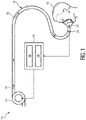
- Fig. 1 schematically illustrates an exemplary embodiment of the respiratory therapy device according to the present invention.
- the device is therein in its entirety denoted by reference numeral 10.
- the respiratory therapy device 10 comprises a gas flow generator 12 (also denoted as pressure generator 12) which is configured to generate a flow of breathing gas. Said generated flow of breathing gas is schematically indicated by arrows 14.
- the breathing gas may include air, oxygen, or a mixture thereof. It is delivered from the gas flow generator 12 to an airway of a patient 16 via a pressure circuit 18.
- the pressure circuit 18 connects the pressure generator 12 to the airway of the patient 16. It may include a conduit or hose 20 which is connected at its a first end to the pressure generator 12 and at its second opposite end to a patient interface 22.
- the patient interface 22 is preferably configured to direct the generated flow of breathing gas 14 to the airway of the patient 16 in a non-invasive manner.
- the patient interface 22 may include a mask, such as a full face mask for covering the nose and mouth, a mouth mask for covering the mouth, a nose mask for covering the nose, or a total face mask for covering most parts of the face including the nose, the mouth and the eyes.
- the pressure support system shown in Fig. 1 is what is usually known as a single-limb system, meaning that the pressure circuit 18 includes only one delivery conduit 20 connecting the patient 16 to the pressure generator 12.
- the pressure support system can be a two-limb system, having a delivery conduit and an exhaust conduit connected to the patient 16.
- the exhaust conduit carries exhaust gas from the patient 16 and includes an exhaust valve at the end distal from the patient 16.
- the pressure therapy device 10 furthermore comprises a sensor 24 and a controller 26.
- the sensor 24 is used for monitoring the breathing pattern of the patient 16. It generates a breathing signal that is indicative of the breathing pattern of the patient 16.
- the sensor 24 may include one or more sensors.
- the sensor 24 may e.g. comprise a flow sensor, a pressure sensor or an electrochemical gas sensor, and may be arranged at or within the patient interface 22 or within the delivery conduit 20 at a position close to the patient interface 22.
- the sensor 24 may include a camera or radar sensor that is arranged remote from the patient 16, the pressure generator 12, and the pressure circuit 18. This camera may monitor the movements of the patient's chest in order to derive the breathing signal.
- a radar sensor may be used for monitoring the chest movements of the patient 16 and thereby deriving the breathing signal.
- the controller 26 is configured to control the pressure generator 12 based on a predefined operating algorithm and based on the breathing signal provided by the sensor 24.
- the controller 26 may include one or more of a digital processor, an analog processor, a digital circuit designed to process information, an analog circuit designed to process information, a state machine and/or other mechanisms for electronically processing information.
- the controller 26 includes a CPU having software stored thereon for carrying out the mechanisms as explained below and for controlling the pressure generator 12 in the way explained below.
- controller 26 is shown in Fig. 1 as a single entity, this is for illustrative purposes only. In some implementations, controller 26 may include a plurality of processing units.
- controller 26 may represent processing functionality of a plurality of devices operating in coordination.
- the controller 26 may be configured to execute one or more computer program modules which are hardware and/or software implemented.
- the one or more computer program modules may include an evaluation module 28 and a pressure generator control module 30.
- the evaluation module 28 is preferably configured to evaluate the breathing signal provided by the sensor 24 in order to detect whether the monitored breathing pattern of the patient 16 includes an ataxic breathing episode.
- the pressure generator control module 30 is preferably configured to control the pressure generator 12 based on the evaluation of the breathing signal provided by the evaluation module 28. According to a preferred embodiment, the pressure generator control module 30 is configured to turn on the pressure generator 12 for providing the pressurized flow of breathing gas 14 only if the evaluation module 28 detects an ataxic breathing episode in the breathing signal provided by the sensor 24. In this case the pressure generator control module 30 preferably controls the pressure generator to provide the flow of breathing gas 14 for a predetermined period of time (herein denoted as first time period) with a volume per minute which is above an individual -related threshold value of the patient 16, wherein said individual-related threshold value corresponds or equals the minute ventilation of the patient 16 during regular breathing when no ataxic breathing occurs.
- first time period herein denoted as first time period
- the pressure generator 12 is in other words controlled to provide a pressurized flow of breathing gas 14 that exceeds the "regular" minute ventilation of the patient 16.
- the provision of a pressurized flow of breathable gas 14 that exceeds the "normal" minute ventilation of the patient 16 results in an elimination of the spontaneous breathing of the patient 16 such that the patient 16 is completely mechanically ventilated by means of the pressure generator 12.
- the elimination of the spontaneous breathing of the patient 16 overrides the person's irregular breathing pattern that occurs during ataxic breathing. This shall help to restore the balance between O 2 and CO 2 , which balance is usually disordered during ataxic breathing, back to normal values again.
- the breathing pattern is thereby re-synchronized in similar way as a hearth rhythm is synchronized by an ICD.
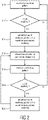
- Fig. 2 shows a block diagram which schematically illustrates a method for re-synchronizing the breathing pattern of the patient 16.
- a first step S10 the breathing pattern of the patient 16 is monitored, e.g. based on the breathing signal provided by the sensor 24.
- the pressurized flow of breathable gas 14 may either be completely turned off or kept at a comparatively low level that allows the patient 16 to breathe spontaneously. This situation may, for example, be the case during time period 32 that is schematically illustrated in the volume flow-over-time graph shown in Fig. 3 .
- the breathing signal provided by sensor 24 may e.g. be sampled in regular intervals in order to detect whether the monitored breathing pattern includes an ataxic breathing episode (see step S12). As long as no ataxic breathing episode is detected in the monitored breathing pattern the method remains in a closed loop between step S10 and step S12.
- the afore -mentioned flow of breathing gas 14 is provided for a predetermined first time period ⁇ t 1 to overdrive the spontaneous breathing of the patient 16 (see step S14).
- a typical volume flow during ataxic breathing is depicted in Fig. 3 in time period 34. It may be seen that during this ataxic breathing time period 34 the amplitude, the frequency, and/or the minute ventilation vary rather strongly compared to regular breathing. It is therefore preferred to identify a part of the monitored breathing pattern of the patient 16 as ataxic breathing episode if a variation over time of one or more of the minute ventilation, the breathing frequency, and the breathing amplitude of the patient 16 is larger than a predetermined threshold.
- the minute ventilation, the breathing frequency, and/or the breathing amplitude are preferably derived from the breathing signal generated by the sensor 24.
- the provision of the gas flow 14 for overdriving spontaneous breathing of the patient 16 during the first time period ⁇ t 1 is schematically illustrated in time span 36 in Fig. 3 . It can be seen that during this time period the volume per minute of the provided breathing gas flow 14 is above the minute ventilation during regular breathing (compare to time period 32 in Fig. 3 ).
- the value for the minute ventilation that is to be set during the first time period ⁇ t 1 may be determined in several ways: One possibility is to determine the minute ventilation of the patient 16 when no ataxic breathing episode is detected in the monitored breathing pattern, e.g. during time period 32, and then to set the volume per minute of the provided gas flow 14 to a value above the determined "normal" minute ventilation (e.g. 10 %, 20 % or 50 % above).
- the second possibility is to use the breathing signal of the sensor 24 while the pressurized flow of breathing gas 14 is slowly ramped up.
- the gas flow sensed by a flow sensor 24 will be influenced by the breathing effort of the patient 16.
- the flow of breathing gas 14 provided by the pressure generator 12 may thus be slowly ramped up until the sensed breathing parameters (e.g. the sensed inhaled and exhaled breathing flow of the patient 16) is synchronized with the flow of breathing gas 14 provided by the pressure generator 12. At this point mechanical ventilation of the patient 16 begins and spontaneous breathing is eliminated. If this point is detected, the controller 26 may control the pressure generator 12 to further increase the volume per minute of the provided flow of breathing gas 14 by an additional predetermined fixed or relative extra value.
- This first time period ⁇ t 1 may be equal to or less than one minute, equal to or less than two minutes, or equal to or less than five minutes.
- the flow of gas 14 is preferably turned off or reduced to a level below the regular minute ventilation of the patient 16.
- Time period 38 schematically illustrated in Fig. 3 shows a corresponding situation. This situation corresponds to method step S16 during which the provision of the gas flow 14 is discontinued/interrupted for at least a second period of time ⁇ t 2 .
- the breathing pattern of the patient 16 is monitored again by the sensor 24 during the second time period ⁇ t 2 (see step S18).
- step S10 If no ataxic breathing episode occurs during time period ⁇ t 2 , the method may return to step S10 (see method step S20).
- the pressure generator 12 may be controlled to again provide the breathing gas flow 14 to overdrive spontaneous breathing of the patient 16 (see step S22).
- the method may afterwards return to step S 16 so as to repeat method steps S16-S22 until no ataxic breathing episodes are detected anymore (see Fig. 2 ).
- the breathing pattern of the patient 16 at first sight returns to a normal state after the first provision of the gas flow 14 during time period 36 (see beginning of time period 38 in Fig. 3 ). However, then ataxic breathing begins again. This could be e.g. the case if the re-synchronization provided during time period 36 has not been enough to completely eliminate ataxic breathing.
- the gas flow 14 is therefore provided again during time period 40 in the example shown in Fig. 3 .
- the controller 26 of the device 10 maybe configured to control the pressure generator 12 to provide the flow of breathing gas this time for a third time period ⁇ t 3 which is longer than the first time period ⁇ t 1 . This shall increase the likelihood of eliminating the occurrence of an ataxic breathing episode.
- the same effect may be achieved if the third time period ⁇ t 3 equals the first time period ⁇ t 1 and the flow rate during the third time period ⁇ t 3 is increased compared to the flow rate applied during the first time period ⁇ t 1 .
- the third time period ⁇ t 3 may even be or shorter than the first time period ⁇ t 1 .
- the provided flow of breathing gas 14 is preferably designed to be an oscillating gas flow. This may include a sinusoidal behavior of the volume flow but may also include indiscrete changes between phases of high level pressure (during inhalation) and phases of low level pressure (during exhalation).
Description
- The present invention relates to a device for re-synchronizing a breathing pattern of a patient suffering from ataxic breathing.
- In recent years the number of patients suffering from ataxic breathing is increasing more and more. Ataxic breathing is an abnormal pattern of breathing characterized by a complete irregularity of breathing. This phenomenon typically only occurs while the patients are sleeping. Patients suffering from ataxic breathing have a very irregular breathing pattern during sleep affecting both frequency and amplitude of breaths.
- It is caused by damage to the medulla oblongata. Neurological changes affect the control loop responsible for breathing and in this way lead to the occurrence of ataxic breathing episodes during sleep. Ataxic breathing is often observed in patients using opiods and has negative effects comparable to those of regular sleep apnea. Due to the comparatively frequent administration of opioids in the US, ataxic breathing has become a more and more frequently observed problem especially (but not only) in the US.
- Due to its irregularity it is difficult to predict the amplitude and timing of the next breath and correspondingly the optimal way of treating ataxic breathing. The most common way of treating ataxic breathing is by means of a positive airway pressure (PAP) therapy. While existing PAP therapy modes are quite suitable for treating "regular" sleep apnea, these existing PAP therapy modes are, however, not optimal for the treatment of ataxic breathing.
-
GB 2 472 116 -
US 2014/0123979 discloses systems and methods for determining patient fatigue during ventilation of a patient. -
EP 0 324 275 discloses a ventilation synchronizer. -
US 2005/0061315 discloses methods and systems which involve monitoring one or more patient conditions using a monitoring device that is fully or partially implantable. -
US 2011/0288609 discloses a method and device for treating a variety of conditions, disorders or diseases with diaphragm/phrenic nerve stimulation. -
EP 1 350 466 discloses a monitor which can detect respiration of a sleeping person without being affected by the attitude of the sleeping person or the indoor illumination light and which can easily evaluate detected respiration quantitatively through image measurement. -
EP 1 410 755 discloses a monitoring device which can detect conditions of a sleeping person. -
WO 2009/138976 discloses monitoring, predicting and treating clinical episodes. A control unit is configured to monitor a condition of the subject by analyzing a physiological parameter and sensed body movement for driving an output unit to generate an alert upon detecting a deterioration of the monitored condition. -
US 2013/0197321 A1 discloses neural monitoring methods and systems for treating upper airway disorders. -
JP 2014 147595 A -
US 2007/221224 A1 discloses a ventilatory control system. - There is therefore still room for improvement.
- It is an object of the present invention to provide an improved device for treating ataxic breathing. The invention is defined in the claims.
- Preferred embodiments of the invention are defined in the dependent claims.
- The proposed device make use of a positive airway pressure treatment which causes a re-synchronization of the breathing of the patient as soon as an ataxic breathing episode is detected. As long as the patient's breathing pattern is within predetermined boundaries and no ataxic breathing episode is detected, preferably no pressure support is applied, i.e. no pressurized flow of breathing gas is supplied to the airway of the patient. However, if the breathing pattern shows signs of ataxic breathing, the generation and delivery of the pressurized flow of breathable gas is initiated. The flow of breathable gas is in this case delivered to the airway of the patient with a volume provided per minute that is above an individual-related threshold value of the patient. This individual-related threshold value of the patient is the amount/volume of breathing gas that the person usually requires during normal breathing. The individual-related threshold value preferably equals the minute ventilation during normal breathing, i.e. during phases in which no ataxic breathing episodes are occurring and the person is at rest or sleeping. Minute ventilation is defined as the volume of gas inhaled or exhaled from a person's lung per minute. It is an important parameter in respiratory medicine due to its relationship with blood carbon dioxide levels. However, it shall be noted that the minute ventilation during regular breathing differs from patient to patient and depends on several anatomical factors, such as height, weight, etc. The threshold value of the volume of the provided breathing gas per minute that is according to the presented method and device exceeded is thus also an individual-related value that may differ from patient to patient.
- Since the afore-mentioned individual-related threshold value, which is indicative of the minute ventilation of the patient during normal breathing, is exceeded, the patient's spontaneous breathing is eliminated during the provision of the pressurized flow of breathable gas. To this end, the patient's breathing is so to say overdriven by means of the externally provided mechanical ventilation. The spontaneous breathing efforts are overruled.
- Supplying a person who is suffering from an irregular breathing pattern with a flow of breathing gas having a volume flow per minute that is well in excess of what the person would need during normal breathing will override the person's irregular breathing pattern and return him/her to more normal breathing. One mechanism behind this effect is that the irregular breathing pattern will throw the normal exchange of 02 and C02 off balance. Providing the afore-mentioned flow of pressurized breathing gas will help restoring the balance of O2 and CO2 to more normal values, which increases the chances of the person being able to start following a more normal spontaneous breathing pattern again.
- In other words, the chemosensors, which are usually not working in a right manner when ataxic breathing is occurring, shall be overruled and the brain shall be stopped from causing neurological signals that lead to the ataxic breathing episodes. Since the spontaneous breathing is eliminated due to the applied breathing gas above the "normally" needed minute ventilation threshold, the breathing pattern is re-synchronized in a similar way as the hearth rhythm is re-synchronized by an implantable cardioverter defibrillator (ICD).
- It is important to note that the patient is within the herein presented method ventilated in a way that eliminates the spontaneous breathing of the patient. This has to be clearly distinguished from PAP treatments such as CPAP or Bi-PAP treatments that are used for treating "regular" sleep apnea diseases. CPAP and Bi-PAP therapy modes make use of lower volume flows, since these therapy modes are intended for preserving the patency of the patient's airway, i.e. for keeping the patient's airway open, but not for mechanically ventilating the patient. CPAP and Bi-PAP therapy modes still allow the patients to breathe spontaneously. In contrast thereto, such a spontaneous breathing is not possible during the provision of the flow of breathing gas in the treatment according to the present invention.
- According to an aspect of the presented method, the step of detecting an ataxic breathing episode includes evaluating one or more of a minute ventilation, a breathing frequency, and a breathing amplitude of the patient, wherein a part of the monitored breathing pattern of the patient is identified as ataxic breathing episode if a variation over time of the one or more of the minute ventilation, the breathing frequency, and the breathing amplitude of the patient is larger than a predetermined threshold.
- According to a correspoding aspect of the presented device, the controller is configured to :
- determine one or more of a minute ventilation, a breathing frequency, and a breathing amplitude of the patient based on the breathing signal;
- evaluate a variation over time of the one or more of the minute ventilation, the breathing frequency, and the breathing amplitude; and
- identify a part of the monitored breathing pattern of the patient as ataxic breathing episode if the variation over time of the one or more of the minute ventilation, the breathing frequency, and the breathing amplitude of the patient is larger than a predetermined threshold.
- Large variations in frequency and/or amplitude which also lead to variations of minute ventilation are usually good indicators for detecting ataxic breathing. The breathing pattern of the patient may be monitored by a sensor, wherein several types of different sensors are generally conceivable to be used.
- According to an aspect of the presented device, the sensor may include at least one of a flow sensor, a pressure sensor, a camera, a radar sensor, an accelerometer, a piezoelectric sensor and an electrochemical gas sensor.
- A flow sensor may e.g. be arranged within the pressure circuit at or close to the patient interface via which the flow of breathing gas is delivered to the airway of the patient.
- A pressure sensor maybe arranged at the same location, either alternatively to the flow sensor or in addition thereto.
- Another way of monitoring the breathing pattern of the patient is by means of a camera. With today's cameras, such as e.g. the Philips Vital Signs Camera, it is no problem to derive a breathing pattern from an optical camera signal. It would be similarly possible to derive the breathing pattern by means of a radar sensor.
- Still alternatively, an accelerometer or piezoelectric sensor could be used for this task, wherein the accelerometer or the piezoelectric sensor is e.g. arranged at the chest of the patient.
- A still further possibility is the usage of an electrochemical gas sensor that is configured to measure the composition of the breathing gas that is exhaled by the patient. This electrochemical gas sensor may also be arranged within the pressure circuit, e.g. at or within the patient interface.
- It shall be noted that independent of the type of sensor that is used, the signal generated by this sensor is herein denoted as breathing signal, as this signal is indicative of the person's breathing pattern. As a consequence, this breathing signal may either be a flow signal, a pressure signal, an optical signal, etc..
- The generated flow of breathing gas that is according to the present disclosure used in the above-mentioned way for re-synchronizing the breathing pattern of the patient is preferably provided only for a comparatively short time period each time an ataxic breathing episode is detected. This time period is herein denoted as first period of time or first time period. This predetermined first period of time is preferably set to be shorter than ten minutes, more preferably shorter than five minutes, most preferably shorter or equal to three minutes.
- In a preferred aspect of the presented method, the method comprises the steps of:
- (i) discontinuing the provision of the breathing gas after the predetermined period of time for at least a second predetermined period of time;
- (ii) monitoring the breathing pattern of the patient during the second predetermined period of time;
- (iii) if an ataxic breathing episode is detected during the second period of time, ventilating the patient and eliminating the spontaneous breathing of the patient again for a predetermined third period of time;
- repeating steps (i) - (iii) until no ataxic breathing episode is detected any more during the second period of time.
- According to a corresponding aspect of the herein presented device, the controller is configured to
- (i) control the pressure generator to discontinue the provision of the breathing gas after the predetermined period of time for at least a second predetermined period of time;
- (ii) control the sensor to monitor the breathing pattern of the patient during the second predetermined period of time; and
- (iii) control the pressure generator, if an ataxic breathing episode is detected during the second period of time, to provide again the flow of breathing gas for a predetermined third period of time with a volume per minute being above the individual-related threshold value of the patient so as to ventilate the patient and eliminate a spontaneous breathing of the patient;
wherein the controller is configured to repeat control steps (i) - (iii) until no ataxic breathing episode is detected any more during the second period of time. - This means, in other words, that after given amount of time the pressure support is reduced or turned off completely and the breathing of the patient is checked to see it the patient's autonomous breathing mechanism has stabilized. The breathing pattern of the patient is then monitored for a herein called second period of time.
- If the breathing pattern continues or starts again to be irregular during this second period of time, the above-described re-synchronization therapy is repeated and the flow of breathing gas is provided for a predetermined third period of time. This third period of time may be equal to the above-mentioned first period of time. However, it may be also shorter or longer than the first period of time.
- If, on the other hand, the breathing pattern stays regular while the breathing pattern of the patient is monitored during the second period of time, pressure support does not have to be picked up again until a new ataxic breathing episode is detected again. In this way a kind of a closed loop control is established.
- According to a further aspect of the presented method, each time step (iii) is repeated, the flow of breathing gas is provided with a volume per minute that is increased compared to the flow of breathing gas provided in a previous step (iii).
- In a corresponding aspect of the presented device, each time control step (iii) is repeated by the controller, the controller controls the pressure generator to provide the flow of breathing gas with a volume per minute that is increased compared to the flow of breathing gas provided in a previous control step (iii).
- The reasoning behind this embodiment is the following: If after the first re-synchronization of the breathing pattern ataxic breathing episodes still occur, then, the next time the volume per minute will be increased in order to increase the likelihood of eliminating the ataxic breathing episodes. Increasing the volume per minute may be achieved either by increasing the flow rate or by increasing the time period of providing the gas flow.
- The above-mentioned individual-related threshold value of the patient, which preferably equals the minute ventilation of the patient during regular breathing, may be determined in several ways.
- According to an aspect of the presented method, the individual-related threshold value of the patient may be determined by determining a minute ventilation of the patient when no ataxic breathing episode is detected in the monitored breathing pattern during sleep.
- In the corresponding aspect of the presented device, the controller is configured to determine the individual-related threshold value of the patient by determining a minute ventilation of the patient based on the breathing signal when no ataxic breathing episode is detected in the breathing pattern.
- The generated flow of breathing gas that is delivered to the patient for re-synchronizing the breathing pattern may e.g. be set to be 20 %, 30 %, or even 50 % above the determined individual-related threshold value (minute ventilation during regular breathing).
- A still further possibility is to set the volume per minute of the generated flow of breathable gas to a fixed value of e.g. 6 1/m, since this value is for most patients above the "regular" minute ventilation and thus eliminates spontaneous breathing in almost all patients. However, such a predetermining of the provided volume per minute is less preferable, if only because need for ventilation differs from patient to patient, as explained above.
- A further possibility of determining the volume flow per minute that is required from eliminating the spontaneous breathing and re-synchronizing the breathing pattern may be the following: In an embodiment of the presented method, the step of ventilating the patient and eliminating the spontaneous breathing of the patient for the first period of time includes sensing one or more breathing parameters of the patient and increasing the volume per minute of the provided flow of breathing gas until the one or more sensed breathing parameters are synchronized with the provided flow of breathing gas, and then further increasing the volume per minute of the provided flow of breathing gas at this point by a predetermined fixed or relative extra value.
- These and other aspects of the invention will be apparent from and elucidated with reference to the embodiments described hereinafter. In the following drawings
-
Fig. 1 schematically illustrates a respiratory therapy device according to an embodiment of the present invention; -
Fig. 2 illustrates an embodiment of a respiratory therapy method according to the present disclosure in form of a block diagram; and -
Fig. 3 shows a schematic graph that illustrates an exemplary volume flow over time of a breathing pattern of a patient. - As used herein, the singular form of "a", "an", and "the" include plural references unless the context clearly dictates otherwise. As used herein, the terms "first", "second" merely distinguish between different components, time periods or features of the same type, but shall not imply any chronological order or a certain amount.
- Directional phrases used herein, such as, for example and without limitation, top, bottom, left, right, upper, lower, front, back, and derivatives thereof, relate to the orientation of the elements shown in the drawings and are not limited upon the claims unless expressly recited therein.
- The embodiments explained in the following are to be merely understood as exemplary embodiments of the herein presented device.
- These embodiments are described for the purpose of illustration based on what is currently considered to be most practical and preferred.
-
Fig. 1 schematically illustrates an exemplary embodiment of the respiratory therapy device according to the present invention. The device is therein in its entirety denoted byreference numeral 10. - The
respiratory therapy device 10 comprises a gas flow generator 12 (also denoted as pressure generator 12) which is configured to generate a flow of breathing gas. Said generated flow of breathing gas is schematically indicated byarrows 14. The breathing gas may include air, oxygen, or a mixture thereof. It is delivered from thegas flow generator 12 to an airway of apatient 16 via apressure circuit 18. - The
pressure circuit 18 connects thepressure generator 12 to the airway of thepatient 16. It may include a conduit orhose 20 which is connected at its a first end to thepressure generator 12 and at its second opposite end to apatient interface 22. Thepatient interface 22 is preferably configured to direct the generated flow of breathinggas 14 to the airway of the patient 16 in a non-invasive manner. Thepatient interface 22 may include a mask, such as a full face mask for covering the nose and mouth, a mouth mask for covering the mouth, a nose mask for covering the nose, or a total face mask for covering most parts of the face including the nose, the mouth and the eyes. - The pressure support system shown in
Fig. 1 is what is usually known as a single-limb system, meaning that thepressure circuit 18 includes only onedelivery conduit 20 connecting the patient 16 to thepressure generator 12. - The present invention also contemplates that the pressure support system can be a two-limb system, having a delivery conduit and an exhaust conduit connected to the
patient 16. In a two-limb system, the exhaust conduit carries exhaust gas from thepatient 16 and includes an exhaust valve at the end distal from thepatient 16. - The
pressure therapy device 10 furthermore comprises asensor 24 and acontroller 26. Thesensor 24 is used for monitoring the breathing pattern of thepatient 16. It generates a breathing signal that is indicative of the breathing pattern of thepatient 16. Thesensor 24 may include one or more sensors. Thesensor 24 may e.g. comprise a flow sensor, a pressure sensor or an electrochemical gas sensor, and may be arranged at or within thepatient interface 22 or within thedelivery conduit 20 at a position close to thepatient interface 22. In an alternative embodiment, thesensor 24 may include a camera or radar sensor that is arranged remote from thepatient 16, thepressure generator 12, and thepressure circuit 18. This camera may monitor the movements of the patient's chest in order to derive the breathing signal. In a still further embodiment a radar sensor may be used for monitoring the chest movements of thepatient 16 and thereby deriving the breathing signal. - The
controller 26 is configured to control thepressure generator 12 based on a predefined operating algorithm and based on the breathing signal provided by thesensor 24. Thecontroller 26 may include one or more of a digital processor, an analog processor, a digital circuit designed to process information, an analog circuit designed to process information, a state machine and/or other mechanisms for electronically processing information. Preferably, thecontroller 26 includes a CPU having software stored thereon for carrying out the mechanisms as explained below and for controlling thepressure generator 12 in the way explained below. Althoughcontroller 26 is shown inFig. 1 as a single entity, this is for illustrative purposes only. In some implementations,controller 26 may include a plurality of processing units. These processing units may be physically located within the same device, orcontroller 26 may represent processing functionality of a plurality of devices operating in coordination. Thecontroller 26 may be configured to execute one or more computer program modules which are hardware and/or software implemented. The one or more computer program modules may include anevaluation module 28 and a pressuregenerator control module 30. - The
evaluation module 28 is preferably configured to evaluate the breathing signal provided by thesensor 24 in order to detect whether the monitored breathing pattern of thepatient 16 includes an ataxic breathing episode. - The pressure
generator control module 30 is preferably configured to control thepressure generator 12 based on the evaluation of the breathing signal provided by theevaluation module 28. According to a preferred embodiment, the pressuregenerator control module 30 is configured to turn on thepressure generator 12 for providing the pressurized flow of breathinggas 14 only if theevaluation module 28 detects an ataxic breathing episode in the breathing signal provided by thesensor 24. In this case the pressuregenerator control module 30 preferably controls the pressure generator to provide the flow of breathinggas 14 for a predetermined period of time (herein denoted as first time period) with a volume per minute which is above an individual -related threshold value of thepatient 16, wherein said individual-related threshold value corresponds or equals the minute ventilation of the patient 16 during regular breathing when no ataxic breathing occurs. - The
pressure generator 12 is in other words controlled to provide a pressurized flow of breathinggas 14 that exceeds the "regular" minute ventilation of thepatient 16. The provision of a pressurized flow ofbreathable gas 14 that exceeds the "normal" minute ventilation of the patient 16 results in an elimination of the spontaneous breathing of the patient 16 such that thepatient 16 is completely mechanically ventilated by means of thepressure generator 12. - The elimination of the spontaneous breathing of the patient 16 overrides the person's irregular breathing pattern that occurs during ataxic breathing. This shall help to restore the balance between O2 and CO2, which balance is usually disordered during ataxic breathing, back to normal values again. The breathing pattern is thereby re-synchronized in similar way as a hearth rhythm is synchronized by an ICD.
-
Fig. 2 shows a block diagram which schematically illustrates a method for re-synchronizing the breathing pattern of thepatient 16. In a first step S10, the breathing pattern of thepatient 16 is monitored, e.g. based on the breathing signal provided by thesensor 24. As long as no ataxic breathing episode occurs, the pressurized flow ofbreathable gas 14 may either be completely turned off or kept at a comparatively low level that allows the patient 16 to breathe spontaneously. This situation may, for example, be the case duringtime period 32 that is schematically illustrated in the volume flow-over-time graph shown inFig. 3 . - The breathing signal provided by
sensor 24 may e.g. be sampled in regular intervals in order to detect whether the monitored breathing pattern includes an ataxic breathing episode (see step S12). As long as no ataxic breathing episode is detected in the monitored breathing pattern the method remains in a closed loop between step S10 and step S12. - If, on the other hand, an ataxic breathing episode is detected in the breathing signal, the afore -mentioned flow of breathing
gas 14 is provided for a predetermined first time period Δt1 to overdrive the spontaneous breathing of the patient 16 (see step S14). - A typical volume flow during ataxic breathing is depicted in
Fig. 3 intime period 34. It may be seen that during this ataxicbreathing time period 34 the amplitude, the frequency, and/or the minute ventilation vary rather strongly compared to regular breathing. It is therefore preferred to identify a part of the monitored breathing pattern of the patient 16 as ataxic breathing episode if a variation over time of one or more of the minute ventilation, the breathing frequency, and the breathing amplitude of thepatient 16 is larger than a predetermined threshold. The minute ventilation, the breathing frequency, and/or the breathing amplitude are preferably derived from the breathing signal generated by thesensor 24. - The provision of the
gas flow 14 for overdriving spontaneous breathing of the patient 16 during the first time period Δt1 is schematically illustrated intime span 36 inFig. 3 . It can be seen that during this time period the volume per minute of the providedbreathing gas flow 14 is above the minute ventilation during regular breathing (compare totime period 32 inFig. 3 ). - The value for the minute ventilation that is to be set during the first time period Δt1 may be determined in several ways:
One possibility is to determine the minute ventilation of the patient 16 when no ataxic breathing episode is detected in the monitored breathing pattern, e.g. duringtime period 32, and then to set the volume per minute of the providedgas flow 14 to a value above the determined "normal" minute ventilation (e.g. 10 %, 20 % or 50 % above). - The second possibility is to use the breathing signal of the
sensor 24 while the pressurized flow of breathinggas 14 is slowly ramped up. As long as thepatient 16 is breathing spontaneously, the gas flow sensed by aflow sensor 24 will be influenced by the breathing effort of thepatient 16. The flow of breathinggas 14 provided by thepressure generator 12 may thus be slowly ramped up until the sensed breathing parameters (e.g. the sensed inhaled and exhaled breathing flow of the patient 16) is synchronized with the flow of breathinggas 14 provided by thepressure generator 12. At this point mechanical ventilation of thepatient 16 begins and spontaneous breathing is eliminated. If this point is detected, thecontroller 26 may control thepressure generator 12 to further increase the volume per minute of the provided flow of breathinggas 14 by an additional predetermined fixed or relative extra value. - It shall be noted that independent of the way how the volume per minute of the
gas flow 14 is determined and set, spontaneous breathing is overdriven only for the predetermined first period of time Δt1. This first time period Δt1 may be equal to or less than one minute, equal to or less than two minutes, or equal to or less than five minutes. After that time period Δt1 the flow ofgas 14 is preferably turned off or reduced to a level below the regular minute ventilation of thepatient 16.Time period 38 schematically illustrated inFig. 3 shows a corresponding situation. This situation corresponds to method step S16 during which the provision of thegas flow 14 is discontinued/interrupted for at least a second period of time Δt2. The breathing pattern of thepatient 16 is monitored again by thesensor 24 during the second time period Δt2 (see step S18). - If no ataxic breathing episode occurs during time period Δt2, the method may return to step S10 (see method step S20).
- If, however, an ataxic breathing episode is detected again during time period Δt2, the
pressure generator 12 may be controlled to again provide thebreathing gas flow 14 to overdrive spontaneous breathing of the patient 16 (see step S22). The method may afterwards return to stepS 16 so as to repeat method steps S16-S22 until no ataxic breathing episodes are detected anymore (seeFig. 2 ). - In the example shown in
Fig. 3 the breathing pattern of the patient 16 at first sight returns to a normal state after the first provision of thegas flow 14 during time period 36 (see beginning oftime period 38 inFig. 3 ). However, then ataxic breathing begins again. This could be e.g. the case if the re-synchronization provided duringtime period 36 has not been enough to completely eliminate ataxic breathing. Thegas flow 14 is therefore provided again duringtime period 40 in the example shown inFig. 3 . Thecontroller 26 of thedevice 10 maybe configured to control thepressure generator 12 to provide the flow of breathing gas this time for a third time period Δt3 which is longer than the first time period Δt1. This shall increase the likelihood of eliminating the occurrence of an ataxic breathing episode. Alternatively, the same effect may be achieved if the third time period Δt3 equals the first time period Δt1 and the flow rate during the third time period Δt3 is increased compared to the flow rate applied during the first time period Δt1. According to an another embodiment, the third time period Δt3 may even be or shorter than the first time period Δt1. - It may be also seen in the example schematically illustrated in
Fig. 3 that the breathing of the patient 16 returns to a normal state without any occurrence of an ataxic breathing episode intime period 42 after the second re-synchronization of the breathing pattern (during time period 40). - Lastly, it shall be noted that the provided flow of breathing
gas 14 is preferably designed to be an oscillating gas flow. This may include a sinusoidal behavior of the volume flow but may also include indiscrete changes between phases of high level pressure (during inhalation) and phases of low level pressure (during exhalation).
Claims (6)
- Device (10) for re-synchronizing a breathing pattern of a patient (16) suffering from ataxic breathing, comprising:- a sensor (24) for monitoring the breathing pattern of the patient (16) during sleep, wherein the sensor (24) generates a breathing signal;- a pressure generator (12) for generating a flow of breathing gas (14);- a pressure circuit (18) including a patient interface (22) for guiding the generated flow of breathing gas to an airway of the patient (16); and- a controller (26) which is configured to:- evaluate the breathing signal in order to detect whether the monitored breathing pattern includes an ataxic breathing episode; and- if an ataxic breathing episode is detected in the breathing signal, control the pressure generator (12) to provide for a predetermined first period of time (Δt1) the flow of breathing gas with a volume per minute being above an individual-related threshold value of the patient (16) so as to completely mechanically ventilate the patient by the pressure generator (12) and eliminate a spontaneous breathing of the patient (16) for said predetermined first period of time (Δt1),
wherein the individual-related threshold equals the minute ventilation during normal phases in which no ataxic breathing episodes are occurring and the patient is let rest or sleeping. - The device according to claim 1, wherein the sensor (24) includes at least one of a flow sensor, a pressure sensor, a camera, a radar sensor, an accelerometer, a piezoelectric sensor and an electrochemical gas sensor.
- The device according to claim 1, wherein the controller (26) is configured to:- determine one or more of a minute ventilation, a breathing frequency, and a breathing amplitude of the patient (16) based on the breathing signal;- evaluate a variation over time of the one or more of the minute ventilation, the breathing frequency, and the breathing amplitude; and- identify a part of the monitored breathing pattern of the patient (16) as ataxic breathing episode if the variation over time of the one or more of the minute ventilation, the breathing frequency, and the breathing amplitude of the patient is larger than a predetermined threshold.
- The device according to claim 1, wherein the controller (26) is configured to:(i) control the pressure generator (12) to discontinue the provision of the breathing gas (24) after the predetermined period of time for at least a second predetermined period of time (Δt2);(ii) control the sensor (24) to monitor the breathing pattern of the patient (16) during the second predetermined period of time (Δt2); and(iii) control the pressure generator (12), if an ataxic breathing episode is detected during the second period of time (Δt2), to provide again the flow of breathing gas (14) for a predetermined third period of time (Δt3) with a volume per minute being above the individual-related threshold value of the patient (16) so as to ventilate the patient (16) and eliminate a spontaneous breathing of the patient (16);
wherein the controller (26) is configured to repeat control steps (i) - (iii) until no ataxic breathing episode is detected any more during the second period of time (Δt2). - The device according to claim 4, wherein each time control step (iii) is repeated by the controller (26), the controller (26) controls the pressure generator (12) to provide the flow of breathing gas (14) with a volume per minute that is increased compared to the flow of breathing gas (14) provided in a previous control step (iii).
- The device according to claim 1, wherein the controller (26) is configured to determine the individual-related threshold value of the patient (16) by determining a minute ventilation of the patient (16) based on the breathing signal when no ataxic breathing episode is detected in the monitored breathing pattern.
Applications Claiming Priority (3)
| Application Number | Priority Date | Filing Date | Title |
|---|---|---|---|
| US201562261359P | 2015-12-01 | 2015-12-01 | |
| EP16150293 | 2016-01-06 | ||
| PCT/EP2016/078220 WO2017093054A1 (en) | 2015-12-01 | 2016-11-21 | Method and device for treating ataxic breathing |
Publications (2)
| Publication Number | Publication Date |
|---|---|
| EP3383463A1 EP3383463A1 (en) | 2018-10-10 |
| EP3383463B1 true EP3383463B1 (en) | 2022-09-07 |
Family
ID=55077412
Family Applications (1)
| Application Number | Title | Priority Date | Filing Date |
|---|---|---|---|
| EP16802008.9A Active EP3383463B1 (en) | 2015-12-01 | 2016-11-21 | Device for treating ataxic breathing |
Country Status (5)
| Country | Link |
|---|---|
| US (1) | US11013457B2 (en) |
| EP (1) | EP3383463B1 (en) |
| JP (1) | JP6885943B2 (en) |
| CN (1) | CN108290019B (en) |
| WO (1) | WO2017093054A1 (en) |
Families Citing this family (3)
| Publication number | Priority date | Publication date | Assignee | Title |
|---|---|---|---|---|
| AU2017252643B2 (en) | 2016-04-19 | 2022-04-14 | Inspire Medical Systems, Inc. | Accelerometer-based sensing for sleep disordered breathing (SDB) care |
| WO2020033613A1 (en) * | 2018-08-09 | 2020-02-13 | Covidien Lp | Video-based patient monitoring systems and associated methods for detecting and monitoring breathing |
| JP2022542581A (en) | 2019-07-25 | 2022-10-05 | インスパイア・メディカル・システムズ・インコーポレイテッド | Systems and methods for operating implantable medical devices based on sensed posture information |
Citations (1)
| Publication number | Priority date | Publication date | Assignee | Title |
|---|---|---|---|---|
| US20070221224A1 (en) * | 2006-03-20 | 2007-09-27 | Ric Investments, Llc | Ventilatory control system |
Family Cites Families (35)
| Publication number | Priority date | Publication date | Assignee | Title |
|---|---|---|---|---|
| FR2517961A1 (en) * | 1981-12-11 | 1983-06-17 | Synthelabo Biomedical | METHOD AND DEVICE FOR CONTROLLING ARTIFICIAL RESPIRATION |
| GB8704104D0 (en) * | 1987-02-21 | 1987-03-25 | Manitoba University Of | Respiratory system load apparatus |
| US5199424A (en) | 1987-06-26 | 1993-04-06 | Sullivan Colin E | Device for monitoring breathing during sleep and control of CPAP treatment that is patient controlled |
| US4915103A (en) * | 1987-12-23 | 1990-04-10 | N. Visveshwara, M.D., Inc. | Ventilation synchronizer |
| US5645054A (en) | 1992-06-01 | 1997-07-08 | Sleepnet Corp. | Device and method for the treatment of sleep apnea syndrome |
| JPH0819610A (en) | 1994-07-05 | 1996-01-23 | Teijin Ltd | Airway positive pressure type breathing assisting device |
| US6000396A (en) * | 1995-08-17 | 1999-12-14 | University Of Florida | Hybrid microprocessor controlled ventilator unit |
| SE9504120D0 (en) * | 1995-11-16 | 1995-11-16 | Siemens Elema Ab | Ventilator for respiratory treatment |
| GB9802382D0 (en) * | 1998-02-04 | 1998-04-01 | Medtronic Inc | Apparatus for management of sleep apnea |
| SE0002806D0 (en) * | 2000-08-01 | 2000-08-01 | Siemens Elema Ab | User interface |
| JP3477166B2 (en) | 2000-12-07 | 2003-12-10 | 学校法人慶應義塾 | Monitoring device |
| EP1410755A4 (en) * | 2001-06-15 | 2009-01-28 | Sumitomo Osaka Cement Co Ltd | Monitoring apparatus |
| JP3764949B2 (en) * | 2003-06-09 | 2006-04-12 | 住友大阪セメント株式会社 | Condition analysis device |
| US7469697B2 (en) | 2003-09-18 | 2008-12-30 | Cardiac Pacemakers, Inc. | Feedback system and method for sleep disordered breathing therapy |
| US20110288609A1 (en) | 2003-10-15 | 2011-11-24 | Rmx, Llc | Therapeutic diaphragm stimulation device and method |
| JP4809779B2 (en) * | 2004-02-05 | 2011-11-09 | アーリーセンス・リミテッド | Prediction and monitoring technology for clinical onset in respiration |
| CN102989069B (en) * | 2004-02-11 | 2018-01-19 | 瑞思迈有限公司 | For treat sleep disorders equipment by the period adjust |
| US7717110B2 (en) | 2004-10-01 | 2010-05-18 | Ric Investments, Llc | Method and apparatus for treating Cheyne-Stokes respiration |
| FR2906474B3 (en) * | 2006-09-29 | 2009-01-09 | Nellcor Puritan Bennett Incorp | SYSTEM AND METHOD FOR CONTROLLING RESPIRATORY THERAPY BASED ON RESPIRATORY EVENTS |
| WO2009138976A2 (en) | 2008-05-12 | 2009-11-19 | Earlysense Ltd | Monitoring, predicting and treating clinical episodes |
| CA2696773A1 (en) | 2007-08-23 | 2009-02-26 | Invacare Corporation | Method and apparatus for adjusting desired pressure in positive airway pressure devices |
| CN102036713A (en) * | 2007-11-12 | 2011-04-27 | 圣莎拉医学股份公司 | Methods relating to breathing disorders |
| CN102333558B (en) | 2009-02-25 | 2015-08-19 | 皇家飞利浦电子股份有限公司 | Automatic pressure titration |
| US9687177B2 (en) * | 2009-07-16 | 2017-06-27 | Resmed Limited | Detection of sleep condition |
| US8701665B2 (en) * | 2009-07-25 | 2014-04-22 | Fleur T Tehrani | Automatic control system for mechanical ventilation for active or passive subjects |
| US9044560B2 (en) | 2010-01-14 | 2015-06-02 | Koninklijke Philips N.V. | Servo ventilation using pressure drop from baseline |
| EP2608832B1 (en) * | 2010-08-27 | 2022-09-28 | ResMed Pty Ltd | Adaptive cycling for respiratory treatment apparatus |
| EP2747817B1 (en) * | 2011-08-25 | 2018-10-10 | Koninklijke Philips N.V. | Apparatus for controlling a ventilation therapy device |
| CA2863049C (en) | 2012-01-26 | 2017-08-29 | Willard Wilson | Neural monitoring methods and systems for treating pharyngeal disorders |
| US9375542B2 (en) | 2012-11-08 | 2016-06-28 | Covidien Lp | Systems and methods for monitoring, managing, and/or preventing fatigue during ventilation |
| JP2014147595A (en) | 2013-02-01 | 2014-08-21 | Daikin Ind Ltd | Living body monitoring system |
| WO2014176576A1 (en) * | 2013-04-25 | 2014-10-30 | Covidien Lp | Systems and methods for determining fluid responsiveness |
| EP3007753B1 (en) * | 2013-06-11 | 2018-11-14 | Koninklijke Philips N.V. | Synchronous airway pressure release ventilation |
| CA2980849A1 (en) * | 2015-03-31 | 2016-10-06 | Fisher & Paykel Healthcare Limited | Methods and apparatus for oxygenation and/or co2 removal |
| US10172724B2 (en) * | 2016-11-23 | 2019-01-08 | Mark Thomas | Harness for upper extremity below-elbow prosthesis |
-
2016
- 2016-11-21 CN CN201680070360.6A patent/CN108290019B/en active Active
- 2016-11-21 US US15/779,906 patent/US11013457B2/en active Active
- 2016-11-21 JP JP2018526901A patent/JP6885943B2/en active Active
- 2016-11-21 EP EP16802008.9A patent/EP3383463B1/en active Active
- 2016-11-21 WO PCT/EP2016/078220 patent/WO2017093054A1/en active Application Filing
Patent Citations (1)
| Publication number | Priority date | Publication date | Assignee | Title |
|---|---|---|---|---|
| US20070221224A1 (en) * | 2006-03-20 | 2007-09-27 | Ric Investments, Llc | Ventilatory control system |
Also Published As
| Publication number | Publication date |
|---|---|
| JP2018535770A (en) | 2018-12-06 |
| WO2017093054A1 (en) | 2017-06-08 |
| CN108290019A (en) | 2018-07-17 |
| EP3383463A1 (en) | 2018-10-10 |
| US11013457B2 (en) | 2021-05-25 |
| CN108290019B (en) | 2021-06-18 |
| JP6885943B2 (en) | 2021-06-16 |
| US20180368758A1 (en) | 2018-12-27 |
Similar Documents
| Publication | Publication Date | Title |
|---|---|---|
| US11229759B2 (en) | Systems and methods for monitoring, managing, and preventing fatigue during ventilation | |
| US8910632B2 (en) | Energy trigger | |
| US8783250B2 (en) | Methods and systems for transitory ventilation support | |
| US8366631B2 (en) | System and method for detecting respiratory events | |
| EP3525857B1 (en) | Systems for drive pressure spontaneous ventilation | |
| US20130025597A1 (en) | Methods and systems for monitoring a ventilated patient with an oximeter | |
| US20130047989A1 (en) | Methods and systems for adjusting tidal volume during ventilation | |
| US20080092894A1 (en) | System and method for controlling respiratory therapy based on detected respiratory events | |
| CN102711888A (en) | Methods and apparatus for adaptable pressure treatment of sleep disordered breathing | |
| AU2005251726A1 (en) | System and method for automated titration of continuous positive airway pressure | |
| EP3383463B1 (en) | Device for treating ataxic breathing | |
| US20090241946A1 (en) | Device for detecting the improper adjustment of a ventilatory support machine used on a mammal | |
| CN109937065B (en) | Bioelectrically controlled ventilation mode | |
| AU2020321288B2 (en) | Device for supportive ventilation of a living being and computer program | |
| US11517691B2 (en) | Methods and systems for high pressure controlled ventilation |
Legal Events
| Date | Code | Title | Description |
|---|---|---|---|
| STAA | Information on the status of an ep patent application or granted ep patent |
Free format text: STATUS: UNKNOWN |
|
| STAA | Information on the status of an ep patent application or granted ep patent |
Free format text: STATUS: THE INTERNATIONAL PUBLICATION HAS BEEN MADE |
|
| PUAI | Public reference made under article 153(3) epc to a published international application that has entered the european phase |
Free format text: ORIGINAL CODE: 0009012 |
|
| STAA | Information on the status of an ep patent application or granted ep patent |
Free format text: STATUS: REQUEST FOR EXAMINATION WAS MADE |
|
| 17P | Request for examination filed |
Effective date: 20180702 |
|
| AK | Designated contracting states |
Kind code of ref document: A1 Designated state(s): AL AT BE BG CH CY CZ DE DK EE ES FI FR GB GR HR HU IE IS IT LI LT LU LV MC MK MT NL NO PL PT RO RS SE SI SK SM TR |
|
| AX | Request for extension of the european patent |
Extension state: BA ME |
|
| DAV | Request for validation of the european patent (deleted) | ||
| DAX | Request for extension of the european patent (deleted) | ||
| RAP1 | Party data changed (applicant data changed or rights of an application transferred) |
Owner name: KONINKLIJKE PHILIPS N.V. |
|
| STAA | Information on the status of an ep patent application or granted ep patent |
Free format text: STATUS: EXAMINATION IS IN PROGRESS |
|
| 17Q | First examination report despatched |
Effective date: 20210407 |
|
| STAA | Information on the status of an ep patent application or granted ep patent |
Free format text: STATUS: EXAMINATION IS IN PROGRESS |
|
| GRAP | Despatch of communication of intention to grant a patent |
Free format text: ORIGINAL CODE: EPIDOSNIGR1 |
|
| STAA | Information on the status of an ep patent application or granted ep patent |
Free format text: STATUS: GRANT OF PATENT IS INTENDED |
|
| RIC1 | Information provided on ipc code assigned before grant |
Ipc: A61B 5/113 20060101ALI20220506BHEP Ipc: A61B 5/08 20060101ALI20220506BHEP Ipc: A61B 5/0205 20060101ALI20220506BHEP Ipc: A61B 5/00 20060101ALI20220506BHEP Ipc: A61B 5/087 20060101ALI20220506BHEP Ipc: A61M 16/00 20060101AFI20220506BHEP |
|
| INTG | Intention to grant announced |
Effective date: 20220530 |
|
| GRAS | Grant fee paid |
Free format text: ORIGINAL CODE: EPIDOSNIGR3 |
|
| GRAA | (expected) grant |
Free format text: ORIGINAL CODE: 0009210 |
|
| STAA | Information on the status of an ep patent application or granted ep patent |
Free format text: STATUS: THE PATENT HAS BEEN GRANTED |
|
| AK | Designated contracting states |
Kind code of ref document: B1 Designated state(s): AL AT BE BG CH CY CZ DE DK EE ES FI FR GB GR HR HU IE IS IT LI LT LU LV MC MK MT NL NO PL PT RO RS SE SI SK SM TR |
|
| REG | Reference to a national code |
Ref country code: GB Ref legal event code: FG4D |
|
| REG | Reference to a national code |
Ref country code: CH Ref legal event code: EP Ref country code: AT Ref legal event code: REF Ref document number: 1516529 Country of ref document: AT Kind code of ref document: T Effective date: 20220915 |
|
| REG | Reference to a national code |
Ref country code: IE Ref legal event code: FG4D |
|
| REG | Reference to a national code |
Ref country code: DE Ref legal event code: R096 Ref document number: 602016074863 Country of ref document: DE |
|
| REG | Reference to a national code |
Ref country code: LT Ref legal event code: MG9D |
|
| REG | Reference to a national code |
Ref country code: NL Ref legal event code: MP Effective date: 20220907 |
|
| PG25 | Lapsed in a contracting state [announced via postgrant information from national office to epo] |
Ref country code: SE Free format text: LAPSE BECAUSE OF FAILURE TO SUBMIT A TRANSLATION OF THE DESCRIPTION OR TO PAY THE FEE WITHIN THE PRESCRIBED TIME-LIMIT Effective date: 20220907 Ref country code: RS Free format text: LAPSE BECAUSE OF FAILURE TO SUBMIT A TRANSLATION OF THE DESCRIPTION OR TO PAY THE FEE WITHIN THE PRESCRIBED TIME-LIMIT Effective date: 20220907 Ref country code: NO Free format text: LAPSE BECAUSE OF FAILURE TO SUBMIT A TRANSLATION OF THE DESCRIPTION OR TO PAY THE FEE WITHIN THE PRESCRIBED TIME-LIMIT Effective date: 20221207 Ref country code: LV Free format text: LAPSE BECAUSE OF FAILURE TO SUBMIT A TRANSLATION OF THE DESCRIPTION OR TO PAY THE FEE WITHIN THE PRESCRIBED TIME-LIMIT Effective date: 20220907 Ref country code: LT Free format text: LAPSE BECAUSE OF FAILURE TO SUBMIT A TRANSLATION OF THE DESCRIPTION OR TO PAY THE FEE WITHIN THE PRESCRIBED TIME-LIMIT Effective date: 20220907 Ref country code: FI Free format text: LAPSE BECAUSE OF FAILURE TO SUBMIT A TRANSLATION OF THE DESCRIPTION OR TO PAY THE FEE WITHIN THE PRESCRIBED TIME-LIMIT Effective date: 20220907 |
|
| REG | Reference to a national code |
Ref country code: AT Ref legal event code: MK05 Ref document number: 1516529 Country of ref document: AT Kind code of ref document: T Effective date: 20220907 |
|
| PG25 | Lapsed in a contracting state [announced via postgrant information from national office to epo] |
Ref country code: HR Free format text: LAPSE BECAUSE OF FAILURE TO SUBMIT A TRANSLATION OF THE DESCRIPTION OR TO PAY THE FEE WITHIN THE PRESCRIBED TIME-LIMIT Effective date: 20220907 Ref country code: GR Free format text: LAPSE BECAUSE OF FAILURE TO SUBMIT A TRANSLATION OF THE DESCRIPTION OR TO PAY THE FEE WITHIN THE PRESCRIBED TIME-LIMIT Effective date: 20221208 |
|
| PG25 | Lapsed in a contracting state [announced via postgrant information from national office to epo] |
Ref country code: SM Free format text: LAPSE BECAUSE OF FAILURE TO SUBMIT A TRANSLATION OF THE DESCRIPTION OR TO PAY THE FEE WITHIN THE PRESCRIBED TIME-LIMIT Effective date: 20220907 Ref country code: RO Free format text: LAPSE BECAUSE OF FAILURE TO SUBMIT A TRANSLATION OF THE DESCRIPTION OR TO PAY THE FEE WITHIN THE PRESCRIBED TIME-LIMIT Effective date: 20220907 Ref country code: PT Free format text: LAPSE BECAUSE OF FAILURE TO SUBMIT A TRANSLATION OF THE DESCRIPTION OR TO PAY THE FEE WITHIN THE PRESCRIBED TIME-LIMIT Effective date: 20230109 Ref country code: ES Free format text: LAPSE BECAUSE OF FAILURE TO SUBMIT A TRANSLATION OF THE DESCRIPTION OR TO PAY THE FEE WITHIN THE PRESCRIBED TIME-LIMIT Effective date: 20220907 Ref country code: CZ Free format text: LAPSE BECAUSE OF FAILURE TO SUBMIT A TRANSLATION OF THE DESCRIPTION OR TO PAY THE FEE WITHIN THE PRESCRIBED TIME-LIMIT Effective date: 20220907 Ref country code: AT Free format text: LAPSE BECAUSE OF FAILURE TO SUBMIT A TRANSLATION OF THE DESCRIPTION OR TO PAY THE FEE WITHIN THE PRESCRIBED TIME-LIMIT Effective date: 20220907 |
|
| PG25 | Lapsed in a contracting state [announced via postgrant information from national office to epo] |
Ref country code: SK Free format text: LAPSE BECAUSE OF FAILURE TO SUBMIT A TRANSLATION OF THE DESCRIPTION OR TO PAY THE FEE WITHIN THE PRESCRIBED TIME-LIMIT Effective date: 20220907 Ref country code: PL Free format text: LAPSE BECAUSE OF FAILURE TO SUBMIT A TRANSLATION OF THE DESCRIPTION OR TO PAY THE FEE WITHIN THE PRESCRIBED TIME-LIMIT Effective date: 20220907 Ref country code: IS Free format text: LAPSE BECAUSE OF FAILURE TO SUBMIT A TRANSLATION OF THE DESCRIPTION OR TO PAY THE FEE WITHIN THE PRESCRIBED TIME-LIMIT Effective date: 20230107 Ref country code: EE Free format text: LAPSE BECAUSE OF FAILURE TO SUBMIT A TRANSLATION OF THE DESCRIPTION OR TO PAY THE FEE WITHIN THE PRESCRIBED TIME-LIMIT Effective date: 20220907 |
|
| REG | Reference to a national code |
Ref country code: DE Ref legal event code: R097 Ref document number: 602016074863 Country of ref document: DE |
|
| PG25 | Lapsed in a contracting state [announced via postgrant information from national office to epo] |
Ref country code: NL Free format text: LAPSE BECAUSE OF FAILURE TO SUBMIT A TRANSLATION OF THE DESCRIPTION OR TO PAY THE FEE WITHIN THE PRESCRIBED TIME-LIMIT Effective date: 20220907 Ref country code: MC Free format text: LAPSE BECAUSE OF FAILURE TO SUBMIT A TRANSLATION OF THE DESCRIPTION OR TO PAY THE FEE WITHIN THE PRESCRIBED TIME-LIMIT Effective date: 20220907 Ref country code: AL Free format text: LAPSE BECAUSE OF FAILURE TO SUBMIT A TRANSLATION OF THE DESCRIPTION OR TO PAY THE FEE WITHIN THE PRESCRIBED TIME-LIMIT Effective date: 20220907 |
|
| REG | Reference to a national code |
Ref country code: CH Ref legal event code: PL |
|
| PLBE | No opposition filed within time limit |
Free format text: ORIGINAL CODE: 0009261 |
|
| STAA | Information on the status of an ep patent application or granted ep patent |
Free format text: STATUS: NO OPPOSITION FILED WITHIN TIME LIMIT |
|
| REG | Reference to a national code |
Ref country code: BE Ref legal event code: MM Effective date: 20221130 |
|
| PG25 | Lapsed in a contracting state [announced via postgrant information from national office to epo] |
Ref country code: LI Free format text: LAPSE BECAUSE OF NON-PAYMENT OF DUE FEES Effective date: 20221130 Ref country code: DK Free format text: LAPSE BECAUSE OF FAILURE TO SUBMIT A TRANSLATION OF THE DESCRIPTION OR TO PAY THE FEE WITHIN THE PRESCRIBED TIME-LIMIT Effective date: 20220907 Ref country code: CH Free format text: LAPSE BECAUSE OF NON-PAYMENT OF DUE FEES Effective date: 20221130 |
|
| 26N | No opposition filed |
Effective date: 20230608 |
|
| PG25 | Lapsed in a contracting state [announced via postgrant information from national office to epo] |
Ref country code: SI Free format text: LAPSE BECAUSE OF FAILURE TO SUBMIT A TRANSLATION OF THE DESCRIPTION OR TO PAY THE FEE WITHIN THE PRESCRIBED TIME-LIMIT Effective date: 20220907 Ref country code: LU Free format text: LAPSE BECAUSE OF NON-PAYMENT OF DUE FEES Effective date: 20221121 |
|
| PG25 | Lapsed in a contracting state [announced via postgrant information from national office to epo] |
Ref country code: IE Free format text: LAPSE BECAUSE OF NON-PAYMENT OF DUE FEES Effective date: 20221121 |
|
| PG25 | Lapsed in a contracting state [announced via postgrant information from national office to epo] |
Ref country code: BE Free format text: LAPSE BECAUSE OF NON-PAYMENT OF DUE FEES Effective date: 20221130 |
|
| PGFP | Annual fee paid to national office [announced via postgrant information from national office to epo] |
Ref country code: GB Payment date: 20231121 Year of fee payment: 8 |
|
| PGFP | Annual fee paid to national office [announced via postgrant information from national office to epo] |
Ref country code: FR Payment date: 20231123 Year of fee payment: 8 Ref country code: DE Payment date: 20231127 Year of fee payment: 8 |
|
| PG25 | Lapsed in a contracting state [announced via postgrant information from national office to epo] |
Ref country code: HU Free format text: LAPSE BECAUSE OF FAILURE TO SUBMIT A TRANSLATION OF THE DESCRIPTION OR TO PAY THE FEE WITHIN THE PRESCRIBED TIME-LIMIT; INVALID AB INITIO Effective date: 20161121 |