EP2747817B1 - Apparatus for controlling a ventilation therapy device - Google Patents
Apparatus for controlling a ventilation therapy device Download PDFInfo
- Publication number
- EP2747817B1 EP2747817B1 EP12778417.1A EP12778417A EP2747817B1 EP 2747817 B1 EP2747817 B1 EP 2747817B1 EP 12778417 A EP12778417 A EP 12778417A EP 2747817 B1 EP2747817 B1 EP 2747817B1
- Authority
- EP
- European Patent Office
- Prior art keywords
- subject
- patient monitor
- parameters
- respiratory therapy
- ventilator
- Prior art date
- Legal status (The legal status is an assumption and is not a legal conclusion. Google has not performed a legal analysis and makes no representation as to the accuracy of the status listed.)
- Active
Links
- 238000009423 ventilation Methods 0.000 title claims description 22
- 238000002560 therapeutic procedure Methods 0.000 title description 6
- 238000004891 communication Methods 0.000 claims description 39
- 238000002644 respiratory therapy Methods 0.000 claims description 26
- 230000029058 respiratory gaseous exchange Effects 0.000 claims description 19
- 238000012545 processing Methods 0.000 claims description 18
- 238000005259 measurement Methods 0.000 claims description 9
- 230000000241 respiratory effect Effects 0.000 claims description 6
- 238000002663 nebulization Methods 0.000 claims 1
- 239000007789 gas Substances 0.000 description 49
- 238000000034 method Methods 0.000 description 19
- CURLTUGMZLYLDI-UHFFFAOYSA-N Carbon dioxide Chemical compound O=C=O CURLTUGMZLYLDI-UHFFFAOYSA-N 0.000 description 8
- 230000008569 process Effects 0.000 description 6
- 229910002092 carbon dioxide Inorganic materials 0.000 description 4
- 239000001569 carbon dioxide Substances 0.000 description 4
- 230000001133 acceleration Effects 0.000 description 3
- QVGXLLKOCUKJST-UHFFFAOYSA-N atomic oxygen Chemical compound [O] QVGXLLKOCUKJST-UHFFFAOYSA-N 0.000 description 3
- 230000005540 biological transmission Effects 0.000 description 3
- 230000000747 cardiac effect Effects 0.000 description 3
- 238000004590 computer program Methods 0.000 description 3
- 230000007246 mechanism Effects 0.000 description 3
- 239000000203 mixture Substances 0.000 description 3
- 229910052760 oxygen Inorganic materials 0.000 description 3
- 239000001301 oxygen Substances 0.000 description 3
- 230000036387 respiratory rate Effects 0.000 description 3
- 230000036772 blood pressure Effects 0.000 description 2
- 230000001276 controlling effect Effects 0.000 description 2
- 230000001419 dependent effect Effects 0.000 description 2
- 239000012530 fluid Substances 0.000 description 2
- 238000012806 monitoring device Methods 0.000 description 2
- 230000007704 transition Effects 0.000 description 2
- 206010039897 Sedation Diseases 0.000 description 1
- 239000008280 blood Substances 0.000 description 1
- 210000004369 blood Anatomy 0.000 description 1
- 230000036760 body temperature Effects 0.000 description 1
- 230000008859 change Effects 0.000 description 1
- 239000000470 constituent Substances 0.000 description 1
- 238000001595 flow curve Methods 0.000 description 1
- 238000003384 imaging method Methods 0.000 description 1
- 230000010365 information processing Effects 0.000 description 1
- 230000003434 inspiratory effect Effects 0.000 description 1
- 210000004072 lung Anatomy 0.000 description 1
- 238000004519 manufacturing process Methods 0.000 description 1
- 238000012986 modification Methods 0.000 description 1
- 230000004048 modification Effects 0.000 description 1
- 238000012544 monitoring process Methods 0.000 description 1
- 230000003287 optical effect Effects 0.000 description 1
- 238000006213 oxygenation reaction Methods 0.000 description 1
- 238000002106 pulse oximetry Methods 0.000 description 1
- 230000001105 regulatory effect Effects 0.000 description 1
- 230000004044 response Effects 0.000 description 1
- 230000036280 sedation Effects 0.000 description 1
- 230000001953 sensory effect Effects 0.000 description 1
- 230000001225 therapeutic effect Effects 0.000 description 1
- 230000003519 ventilatory effect Effects 0.000 description 1
- 230000000007 visual effect Effects 0.000 description 1
Images

Classifications
-
- A—HUMAN NECESSITIES
- A61—MEDICAL OR VETERINARY SCIENCE; HYGIENE
- A61B—DIAGNOSIS; SURGERY; IDENTIFICATION
- A61B5/00—Measuring for diagnostic purposes; Identification of persons
- A61B5/48—Other medical applications
- A61B5/4836—Diagnosis combined with treatment in closed-loop systems or methods
-
- A—HUMAN NECESSITIES
- A61—MEDICAL OR VETERINARY SCIENCE; HYGIENE
- A61M—DEVICES FOR INTRODUCING MEDIA INTO, OR ONTO, THE BODY; DEVICES FOR TRANSDUCING BODY MEDIA OR FOR TAKING MEDIA FROM THE BODY; DEVICES FOR PRODUCING OR ENDING SLEEP OR STUPOR
- A61M16/00—Devices for influencing the respiratory system of patients by gas treatment, e.g. mouth-to-mouth respiration; Tracheal tubes
- A61M16/0051—Devices for influencing the respiratory system of patients by gas treatment, e.g. mouth-to-mouth respiration; Tracheal tubes with alarm devices
-
- A—HUMAN NECESSITIES
- A61—MEDICAL OR VETERINARY SCIENCE; HYGIENE
- A61M—DEVICES FOR INTRODUCING MEDIA INTO, OR ONTO, THE BODY; DEVICES FOR TRANSDUCING BODY MEDIA OR FOR TAKING MEDIA FROM THE BODY; DEVICES FOR PRODUCING OR ENDING SLEEP OR STUPOR
- A61M16/00—Devices for influencing the respiratory system of patients by gas treatment, e.g. mouth-to-mouth respiration; Tracheal tubes
- A61M16/0057—Pumps therefor
- A61M16/0066—Blowers or centrifugal pumps
- A61M16/0069—Blowers or centrifugal pumps the speed thereof being controlled by respiratory parameters, e.g. by inhalation
-
- A—HUMAN NECESSITIES
- A61—MEDICAL OR VETERINARY SCIENCE; HYGIENE
- A61M—DEVICES FOR INTRODUCING MEDIA INTO, OR ONTO, THE BODY; DEVICES FOR TRANSDUCING BODY MEDIA OR FOR TAKING MEDIA FROM THE BODY; DEVICES FOR PRODUCING OR ENDING SLEEP OR STUPOR
- A61M16/00—Devices for influencing the respiratory system of patients by gas treatment, e.g. mouth-to-mouth respiration; Tracheal tubes
- A61M16/021—Devices for influencing the respiratory system of patients by gas treatment, e.g. mouth-to-mouth respiration; Tracheal tubes operated by electrical means
- A61M16/022—Control means therefor
- A61M16/024—Control means therefor including calculation means, e.g. using a processor
-
- A—HUMAN NECESSITIES
- A61—MEDICAL OR VETERINARY SCIENCE; HYGIENE
- A61M—DEVICES FOR INTRODUCING MEDIA INTO, OR ONTO, THE BODY; DEVICES FOR TRANSDUCING BODY MEDIA OR FOR TAKING MEDIA FROM THE BODY; DEVICES FOR PRODUCING OR ENDING SLEEP OR STUPOR
- A61M16/00—Devices for influencing the respiratory system of patients by gas treatment, e.g. mouth-to-mouth respiration; Tracheal tubes
- A61M16/10—Preparation of respiratory gases or vapours
- A61M16/14—Preparation of respiratory gases or vapours by mixing different fluids, one of them being in a liquid phase
- A61M16/16—Devices to humidify the respiration air
- A61M16/161—Devices to humidify the respiration air with means for measuring the humidity
-
- A—HUMAN NECESSITIES
- A61—MEDICAL OR VETERINARY SCIENCE; HYGIENE
- A61M—DEVICES FOR INTRODUCING MEDIA INTO, OR ONTO, THE BODY; DEVICES FOR TRANSDUCING BODY MEDIA OR FOR TAKING MEDIA FROM THE BODY; DEVICES FOR PRODUCING OR ENDING SLEEP OR STUPOR
- A61M2205/00—General characteristics of the apparatus
- A61M2205/18—General characteristics of the apparatus with alarm
-
- A—HUMAN NECESSITIES
- A61—MEDICAL OR VETERINARY SCIENCE; HYGIENE
- A61M—DEVICES FOR INTRODUCING MEDIA INTO, OR ONTO, THE BODY; DEVICES FOR TRANSDUCING BODY MEDIA OR FOR TAKING MEDIA FROM THE BODY; DEVICES FOR PRODUCING OR ENDING SLEEP OR STUPOR
- A61M2205/00—General characteristics of the apparatus
- A61M2205/33—Controlling, regulating or measuring
- A61M2205/3365—Rotational speed
-
- A—HUMAN NECESSITIES
- A61—MEDICAL OR VETERINARY SCIENCE; HYGIENE
- A61M—DEVICES FOR INTRODUCING MEDIA INTO, OR ONTO, THE BODY; DEVICES FOR TRANSDUCING BODY MEDIA OR FOR TAKING MEDIA FROM THE BODY; DEVICES FOR PRODUCING OR ENDING SLEEP OR STUPOR
- A61M2205/00—General characteristics of the apparatus
- A61M2205/50—General characteristics of the apparatus with microprocessors or computers
- A61M2205/502—User interfaces, e.g. screens or keyboards
- A61M2205/505—Touch-screens; Virtual keyboard or keypads; Virtual buttons; Soft keys; Mouse touches
-
- A—HUMAN NECESSITIES
- A61—MEDICAL OR VETERINARY SCIENCE; HYGIENE
- A61M—DEVICES FOR INTRODUCING MEDIA INTO, OR ONTO, THE BODY; DEVICES FOR TRANSDUCING BODY MEDIA OR FOR TAKING MEDIA FROM THE BODY; DEVICES FOR PRODUCING OR ENDING SLEEP OR STUPOR
- A61M2205/00—General characteristics of the apparatus
- A61M2205/50—General characteristics of the apparatus with microprocessors or computers
- A61M2205/52—General characteristics of the apparatus with microprocessors or computers with memories providing a history of measured variating parameters of apparatus or patient
-
- A—HUMAN NECESSITIES
- A61—MEDICAL OR VETERINARY SCIENCE; HYGIENE
- A61M—DEVICES FOR INTRODUCING MEDIA INTO, OR ONTO, THE BODY; DEVICES FOR TRANSDUCING BODY MEDIA OR FOR TAKING MEDIA FROM THE BODY; DEVICES FOR PRODUCING OR ENDING SLEEP OR STUPOR
- A61M2230/00—Measuring parameters of the user
- A61M2230/005—Parameter used as control input for the apparatus
-
- A—HUMAN NECESSITIES
- A61—MEDICAL OR VETERINARY SCIENCE; HYGIENE
- A61M—DEVICES FOR INTRODUCING MEDIA INTO, OR ONTO, THE BODY; DEVICES FOR TRANSDUCING BODY MEDIA OR FOR TAKING MEDIA FROM THE BODY; DEVICES FOR PRODUCING OR ENDING SLEEP OR STUPOR
- A61M2230/00—Measuring parameters of the user
- A61M2230/04—Heartbeat characteristics, e.g. ECG, blood pressure modulation
- A61M2230/06—Heartbeat rate only
-
- A—HUMAN NECESSITIES
- A61—MEDICAL OR VETERINARY SCIENCE; HYGIENE
- A61M—DEVICES FOR INTRODUCING MEDIA INTO, OR ONTO, THE BODY; DEVICES FOR TRANSDUCING BODY MEDIA OR FOR TAKING MEDIA FROM THE BODY; DEVICES FOR PRODUCING OR ENDING SLEEP OR STUPOR
- A61M2230/00—Measuring parameters of the user
- A61M2230/08—Other bio-electrical signals
- A61M2230/10—Electroencephalographic signals
-
- A—HUMAN NECESSITIES
- A61—MEDICAL OR VETERINARY SCIENCE; HYGIENE
- A61M—DEVICES FOR INTRODUCING MEDIA INTO, OR ONTO, THE BODY; DEVICES FOR TRANSDUCING BODY MEDIA OR FOR TAKING MEDIA FROM THE BODY; DEVICES FOR PRODUCING OR ENDING SLEEP OR STUPOR
- A61M2230/00—Measuring parameters of the user
- A61M2230/20—Blood composition characteristics
- A61M2230/205—Blood composition characteristics partial oxygen pressure (P-O2)
-
- A—HUMAN NECESSITIES
- A61—MEDICAL OR VETERINARY SCIENCE; HYGIENE
- A61M—DEVICES FOR INTRODUCING MEDIA INTO, OR ONTO, THE BODY; DEVICES FOR TRANSDUCING BODY MEDIA OR FOR TAKING MEDIA FROM THE BODY; DEVICES FOR PRODUCING OR ENDING SLEEP OR STUPOR
- A61M2230/00—Measuring parameters of the user
- A61M2230/40—Respiratory characteristics
- A61M2230/43—Composition of exhalation
- A61M2230/432—Composition of exhalation partial CO2 pressure (P-CO2)
-
- A—HUMAN NECESSITIES
- A61—MEDICAL OR VETERINARY SCIENCE; HYGIENE
- A61M—DEVICES FOR INTRODUCING MEDIA INTO, OR ONTO, THE BODY; DEVICES FOR TRANSDUCING BODY MEDIA OR FOR TAKING MEDIA FROM THE BODY; DEVICES FOR PRODUCING OR ENDING SLEEP OR STUPOR
- A61M2230/00—Measuring parameters of the user
- A61M2230/50—Temperature
Definitions
- the present disclosure pertains to a method and apparatus controlling a ventilation therapy device, and, in particular, using physiological parameters, such as conveyed via a (patient) monitor signals and/or other physiological monitor signals, for closed-loop control of respiratory therapy regimens provided through a ventilator.
- gas parameters such as pressure, flow, volume, gas mix, and/or other gas parameters
- patient monitors provide a variety of useful real-time information related to physiological parameters, such as heart rate, blood pressure, cardiac output, oxygen saturation, end-tidal carbon dioxide, and/or other physiological parameters of a subject.
- US7225809 discloses a pressure support system with a controller, wherein signals from various sensors may be provided to the controller.
- GB2396426 discloses an artificial respiration system communicating with an electrical impedance imaging system.
- the ventilator comprises a pressure generator, a subject interface, a communications transceiver, and one or more processors.
- the pressure generator may be configured to generate a pressurized flow of breathable gas for delivery to the airway of a subject.
- the subject interface may be configured to interface between the pressure generator and a breathing circuit to deliver the pressurized flow of breathable gas to an artificial airway (e.g . endotracheal or tracheostomy tubes) or the natural airway of the subject through the outlet.
- the communications transceiver may be configured to receive communication signals from a patient monitor device, the communication signals comprising information related to physiological parameters of the subject, the patient monitor device being a separate and discrete device from the ventilator.
- a plurality of ventilation sensors are configured to generate one or more output signals conveying measurements related to respiratory parameters of the subject.
- a communications transceiver is configured to receive communication signals from the patient monitor device.
- the one or more processors may be configured to execute processing modules, including a control module and a regimen adjustment module.
- the control module may be configured to control the pressure generator such that one or more gas parameters of the pressurized flow of breathable gas are varied over time in accordance with a respiratory therapy regimen.
- the regimen adjustment module may be configured to determine adjustments to respiratory therapy regimens based on the communication signals received from the patient monitor device such that the physiological parameters indicated in the communications signals are used for closed-loop control to adjust the respiratory therapy regimen.
- the patient monitor device includes one or more patient monitor sensors.
- the patient monitor device is a separate and discrete device from the ventilator.
- the patient monitor sensors are configured to generate output signals conveying information related to the physiological parameters of the subject.
- the processing modules further comprising a parameter determination module configured to determine one or more parameters from the output signals generated by the plurality of ventilation sensors and one or more patient monitor sensors. Executing of the processing modules is based on the simultaneous use of output signals generated by the ventilation sensors and the patient monitor sensors.
- the word "unitary” means a component is created as a single piece or unit. That is, a component that includes pieces that are created separately and then coupled together as a unit is not a “unitary” component or body.
- the statement that two or more parts or components "engage” one another shall mean that the parts exert a force against one another either directly or through one or more intermediate parts or components.
- the term “number” shall mean one or an integer greater than one ( i.e. , a plurality).
- FIG. 1 illustrates a ventilator device 100 configured to deliver respiratory therapy to a subject 106.
- ventilator device 100 may be configured to mechanically ventilate subject 106 by providing a pressurized flow of breathable gas to an artifical airway of subject 106 or to the natural airway of subject 106 to inflate and/or deflate the lungs of subject 106.
- the respiratory therapy regimen is configured to support the breathing of subject 106.
- the respiratory therapy regimen is configured to cause subject 106 to breathe without any respiratory effort from subject 106.
- Ventilator device 100 may be configured such that the respiratory therapy regimen is controlled in a closed-loop manner using one or more physiological parameters, thus providing real-time control of oxygenation, ventilation, pressure support, and/or other services related to ventilation.
- Ventilator device 100 may include one or more of a pressurized flow generator 140, a subject interface 180 (i.e. outlet for gas output and/or a combination of outlet and inlet), a subject interface appliance 184, a communications transceiver 160, one or more processors 110, and/or other components. Ventilator device 100 may operate in conjunction with a patient monitor device 150, which is a separate and discrete device from ventilator device 100, as indicated by the dotted box representing patient monitor device 150 in FIG. 1 .
- Patient monitor device 150 may be configured to monitor one or more physiological parameters of subject 106.
- patient monitor device 150 may comprise a stand-alone physiological monitor rather than a standard patient monitor.
- Patient monitor device 150 may include, for example, a conventional monitoring device that measures a subject's vital signs and displays the data obtained through the measurements on an electronic display and/or transmits the data on a monitoring network.
- the physiological parameters may include one or more of blood pressure, heart rate, pulse oximetry, blood gas level, ECG, EEG, body temperature, (end-tidal) carbon dioxide concentration, parameters indicating pending cardiac conditions, cardiac output, sedation index and/or other physiological parameters.
- patient monitor device 150 may include one or more of the IntelliVue patient monitors by Philips (e.g ., IntelliVue MP90, MMX800, MMS X2), SureSigns patient monitors by Philips (e.g ., SureSigns VM8), and/or other patient monitoring devices.
- Patient monitor device 150 may include one or more of an electronic display, one or more patient monitor sensors 143, a user interface, one or more processors, and/or other components.
- Patient monitor sensors 143 are configured to generate output signals conveying information related to physiological parameters, as described above, of subject 106.
- Patient monitor sensors 143 may be integrated and/or coupled to patient monitor device 150.
- patient monitor sensors 143 may be separate and discrete from patient monitor device 150, and configured such that the output signals generated by patient monitor sensors 143 may be transmitted to patient monitor device 150 and/or ventilator device 100 (or a component thereof). This transmission may be accomplished via wired and/or wireless communication media.
- the illustration of patient monitor sensor 143 as including a single member in FIG. 1 is not intended to be limiting.
- Pressure generator 140 of ventilator device 100 may be integrated, combined, coupled, or connected with an airway pressure device.
- Respiratory therapy may recommend delivery of a pressurized flow of breathable gas to the airway of a subject, providing one or more inhalation pressure, flow, and/or volume levels during the inhalation phase, and one or more exhalation pressure, flow, and/or volume levels during the exhalation phase.
- Any pressure level during an inhalation phase may be referred to as an inhalation pressure level, though such a pressure level need not be constant throughout the inhalation phase.
- the inhalation pressure level may ramp up or down according to a predetermined slope (absolute and/or relative, e.g. dependent on breathing rate) for any specified section of a phase.
- the flow level during inhalation can follow a predetermined flow waveform like a square or ramp. Similar features may be available for exhalation phases.
- the pressure and/or flow levels may be either predetermined and fixed, follow a predetermined dynamic characteristic, or they may dynamically change breath-to-breath or over several breaths.
- Pressure generator 140 of ventilator device 100 may be configured to provide a pressurized flow of breathable gas to the airway of subject 106.
- Subject 106 may or may not initiate one or more phases of respiration.
- Ventilatory support may be implemented as a higher and lower positive pressure of a (multi-level) PAP device.
- the pressure of the pressurized flow of breathable gas may be adjusted to an inspiratory pressure and/or may be adjusted to a flow level.
- the pressure of the pressurized flow of breathable gas may be adjusted to an expiratory pressure.
- VCV Volume Control Ventilation
- PCV Pressure Control Ventilation
- APRV Airway Pressure Release Ventilation
- PRVC Pressure Regulated Volume Control
- CPAP CPAP, BiPAP®, and/or other schemes
- Ventilator device 100 may be configured such that one or more gas parameters of the pressurized flow of breathable gas are controlled in accordance with a therapeutic respiratory regimen for subject 106.
- the one or more gas parameters may include one or more of flow, volume, pressure, humidity, gas mix, velocity, acceleration, (intentional) gas leak, and/or other parameters.
- Ventilator device 100 may be configured to provide types of therapy including types of therapy where a subject performs inspiration and/or expiration of his/her own accord and/or where the device provides mandatory controlled breaths.
- a pressurized flow of breathable gas may be delivered by pressure generator 140 to or near the airway of subject 106 via a subject interface 180 (also referred to herein as an outlet).
- Subject interface 180 may include a conduit 182, a subject interface appliance 184, and/or other components.
- Conduit 182 may be a single-limb or a dual-limb flexible length of hose, or other conduit, that places subject interface appliance 184 in fluid communication with pressure generator 140.
- Conduit 182 forms a flow path through which the pressurized flow of breathable gas is communicated between subject interface appliance 184 and pressure generator 140.
- Subject interface appliance 184 of ventilator device 100 in FIG. 1 is configured to deliver the pressurized flow of breathable gas to the airway of subject 106.
- subject interface appliance 184 may include any appliance suitable for this function.
- pressure generator 140 is a dedicated ventilation device and subject interface appliance 184 is configured to be removably coupled with another interface appliance being used to deliver respiratory therapy to subject 106.
- subject interface appliance 184 is configured to engage with and/or be inserted into an endotracheal tube, a tracheotomy portal, and/or other interface appliances.
- subject interface appliance 184 is configured to engage the airway of subject 106 without an intervening appliance.
- subject interface appliance 184 includes one or more of an endotracheal tube, a nasal cannula, a tracheotomy tube, a nasal mask, a nasal/oral mask, a full face mask, a total face mask, a partial rebreathing mask, or other interface appliances that communicate a flow of gas with an airway of a subject.
- the present disclosure is not limited to these examples, and contemplates delivery of the pressurized flow of breathable gas to subject 106 using any subject interface.
- ventilator device 100 may include electronic storage 130 comprising electronic storage media that electronically stores information.
- the electronic storage media of electronic storage 130 includes one or both of system storage/ventilator device storage that is provided integrally ( i.e ., substantially non-removable) with ventilator device 100 and/or removable storage that is removably connectable to ventilator device 100 via, for example, a port ( e.g., a USB port, a FireWire port, etc .) or a drive ( e.g ., a disk drive, etc .).
- a port e.g., a USB port, a FireWire port, etc .
- a drive e.g ., a disk drive, etc .
- Electronic storage 130 may include one or more of optically readable storage media (e.g ., optical disks, etc .), magnetically readable storage media (e.g., magnetic tape, magnetic hard drive, floppy drive, etc .), electrical charge-based storage media (e.g ., EEPROM, RAM, etc .), solid-state storage media (e.g ., flash drive, etc .), and/or other electronically readable storage media.
- Electronic storage 130 stores software algorithms, information determined by processor 110, information received via user interface 120, and/or other information that enables ventilator device 100 to function properly.
- electronic storage 130 may record or store timing information (including duration of inhalation phases and exhalation phases as well as transitional moments therebetween), one or more (breathing) parameters and/or other parameters (as discussed elsewhere herein), pressure levels, information indicating whether the subject adequately complied with a prescribed respiratory therapy regimen, information indicating adequacy of treatment, and/or other information.
- Electronic storage 130 may be a separate component within ventilator device 100, or electronic storage 130 may be provided integrally with one or more other components of ventilator device 100 ( e.g ., processor 110).
- Patient monitor device 150 may include electronic storage having substantially similar functionality and capability as electronic storage 130, though pertaining to patient monitor 150 rather than ventilator device 100.
- User interface 120 of ventilator device 100 in FIG. 1 is configured to provide an interface between ventilator device 100 and a user (e.g ., user 108, subject 106, a caregiver, a therapy decision-maker, etc .) through which the user can provide information to and receive information from ventilator device 100.
- a user e.g ., user 108, subject 106, a caregiver, a therapy decision-maker, etc .
- This enables data, results, and/or instructions and any other communicable items, collectively referred to as "information,” to be communicated between the user and ventilator device 100.
- Examples of interface devices suitable for inclusion in user interface 120 include a keypad, buttons, switches, a keyboard, knobs, levers, a display screen, a touch screen, smartphones, smart touchpads, speakers, a microphone, an indicator light, an audible alarm, and a printer.
- Information is e.g . provided to subject 106 by user interface 120 in the form of auditory signals, visual signals, tactile signals
- user interface 120 is integrated with a removable storage interface provided by electronic storage 130.
- information is loaded into ventilator device 100 from removable storage (e.g ., a smart card, a flash drive, a removable disk, etc .) that enables the user(s) to customize the implementation of ventilator device 100.
- removable storage e.g ., a smart card, a flash drive, a removable disk, etc .
- Other exemplary input devices and techniques adapted for use with ventilator device 100 as user interface 120 include, but are not limited to, an RS-232 port, RF link, an IR link, modem (telephone, cable, Ethernet, internet or other), mobile phone and other wireless communication channels.
- any technique for communicating information with ventilator device 100 is contemplated as user interface 120.
- Patient monitor device 150 may include a user interface having substantially similar functionality and capability as user interface 120, though pertaining to patient monitor 150 rather than ventilator device 100.
- Ventilation sensors 142 of ventilator device 100 in FIG. 1 is configured to generate one or more output signals conveying measurements related to the ventilation, oxygen saturation, and/or end-tidal carbon dioxide of subject 106.
- the measurements may relate to gas parameters and/or other parameters.
- Gas parameters may include flow, pressure, humidity, velocity, acceleration, and/or other gas parameters related to the pressurized flow of breathable gas delivered to subject 106.
- Output signals may convey measurements related to respiratory parameters.
- Ventilation sensor(s) 142 may be in fluid communication with conduit 182 and/or subject interface appliance 184.
- ventilation sensor 142 includes a plurality of sensors operating as described above by generating output signals conveying information related to parameters associated with the gas breathed by subject 106, the delivery of the gas to subject 106, oxygen saturation of subject 106, and/or end-tidal carbon dioxide of subject 106.
- a parameter may be related to a mechanical unit of measurement of a component of ventilator device 100 such as rotor speed, motor speed, blower speed, fan speed, or a related measurement that serves as a proxy for any of the breathing parameters listed herein through a previously known/calibrated mathematical relationship.
- Resulting signals or information from sensor 142 may be transmitted to processor 110, user interface 120, electronic storage 130, and/or other components of ventilator device 100. This transmission can be wired and/or wireless.
- Communications transceiver 160 of ventilator device 100 in FIG. 1 is configured to receive communication signals from patient monitor 150, which is a separate and discrete device from ventilator device 100.
- the communication signals may comprise information related to physiological parameters of subject 106.
- the communication signals may comprise the same signals and/or information as one or more patient monitor sensors 143.
- the communication signals may comprise data that is determined and/or generated by patient monitor device 150 based on output signals from patient monitor sensors 143.
- Such data may for example include minimum, maximum, mean, and/or average measured values, trend data for a particular patient monitor sensor 143 and/or a physiological parameter derived thereof, e.g . within a configurable period such as a minute, an hour, a day, a week, and/or another predetermined period.
- Communication signals may comprise information based on multiple signals and/or multiple physiological parameters derived therefrom.
- communications transceiver 160 may be configured to transmit signals, information, and/or alarms to patient monitor 150, e.g. for presentation on the user interface and/or the electronic display of patient monitor device 150.
- a component of ventilator device 100 may determine a (real-time and/or continuous) parameter that is displayed on patient monitor 150, after transmission through communications transceiver 160. Such a parameter may be displayed along with other parameters based on output signals from patient monitor sensors 143.
- Processor 110 of ventilator device 100 in FIG. 1 is configured to provide information processing capabilities within ventilator device 100.
- processor 110 includes one or more of a digital processor, an analog processor, a digital circuit designed to process information, an analog circuit designed to process information, a state machine, and/or other mechanisms for electronically processing information.
- processor 110 is shown in FIG. 1 as a single entity, this is for illustrative purposes only. In some embodiments, processor 110 includes a plurality of processing units.
- Patient monitor device 150 may include one or more processors having substantially similar functionality and capability as processor 110, though pertaining to patient monitor 150 (and its components) rather than ventilator device 100 (and its components).
- processor 110 is configured to execute one or more computer program modules.
- the one or more computer program modules include one or more of a parameter determination module 111, a control module 112, a regimen adjustment module 113, an alarm module 114, and/or other modules.
- Processor 110 may be configured to execute modules 111, 112, 113, and/or 114 by software; hardware; firmware; some combination of software, hardware, and/or firmware; and/or other mechanisms for configuring processing capabilities on processor 110.
- Processor 110 may be configured to execute one or more modules that receive and/or process the output signals generated by patient monitor sensors 143 and/or ventilation sensors 142. Based on the output signals generated by patient monitor sensors 143, the processing modules may monitor the physiological parameters of subject 106. The processing modules are further configured to present information related to at least one physiological parameter.
- Processor 110 may be configured to execute one or more modules that receive and/or process signals and/or information obtained from patient monitor device 150.
- modules 111, 112, 113, and 114 are illustrated in FIG. 1 as being co-located within a single processing unit, in embodiments in which processor 110 includes multiple processing units, one or more of modules 111, 112, 113, and/or 114 may be located remotely from the other modules.
- the description of the functionality provided by the different modules 111, 112, 113, and/or 114 described below is for illustrative purposes, and is not intended to be limiting, as any of modules 111, 112, 113, and/or 114 may provide more or less functionality than is described.
- modules 111, 112, 113, and/or 114 may be eliminated, and some or all of its functionality may be provided by other ones of modules 111, 112, 113, and/or 114.
- processor 110 may be configured to execute one or more additional modules that may perform some or all of the functionality attributed below to one of modules 111, 112, 113, and/or 114.
- one or more of modules 111, 112, 113, and 114, and/or some or all of their respective functionalities may be provided by patient monitor device 150 (or components thereof).
- Parameter determination module 111 is configured to determine one or more gas parameter, breathing parameters, and/or other parameters from the output signals generated by patient monitor sensors 143 and/or ventilation sensors 142.
- Gas parameters of the (pressurized) flow of breathable gas may include one or more of (peak) flow, pressure, temperature, humidity, velocity, acceleration, gas composition ( e.g . concentration(s) of one or more constituents), thermal energy dissipated, (intentional) gas leak, and/or other gas parameters related to the (pressurized) flow of breathable gas.
- Breathing parameters may be derived from the one or more gas parameters, and include one or more of tidal volume of the breathing of the subject, retrograde volume, respiratory rate, breathing period, inhalation time or period, exhalation time or period, inhalation volume, exhalation volume, peak flow, flow rate of the breathing of the subject, respiration flow curve shape, transition time from inhalation to exhalation and/or vice versa, transition time from peak inhalation flow rate to peak exhalation flow rate and/or vice versa, respiration pressure curve shape, pressure-volume loops, flow-volume loops, (intentional) gas leak, and/or other breathing parameters.
- parameter determination module 111 may be incorporated or integrated into other computer program modules of processor 110 and/or patient monitor device 150.
- Control module 112 is configured to control pressure generator 140 such that one or more gas parameters of the pressurized flow of breathable gas are varied over time in accordance with a respiratory therapy regimen.
- Control module 112 may be configured to control pressure generator 140 to provide the pressurized flow of breathable gas at inhalation pressure levels during inhalation phases, and at exhalation pressure levels during exhalation phases.
- Parameters determined by parameter determination module 111 (and/or received through patient monitor sensors 143) may be used by control module 112, e.g. in a feedback manner, to adjust ventilator settings/operations.
- signals and/or information received by communications transceiver 160 may be used by control module 112, e.g. in a feedback manner, to adjust ventilator settings/operations.
- Control module 112 may be configured to time its operations relative to the transitional moments in the breathing cycle of a subject and over multiple breath cycles.
- Regimen adjustment module 113 is configured to determine adjustments to the respiratory therapy regimen. Adjustments may be based on communication signals received from patient monitor device 150 such that the physiological parameters indicated in the communication signals are used as closed-loop control parameters in adjusting the respiratory therapy regimen. Alternatively, and/or simultaneously, adjustments may be based on parameters determined by parameter determination module 111. Once determined, the adjustments may be implemented by regimen adjustment module 113, control module 112, and/or other components of ventilator device 100. In some embodiments, the communication signals are related in a known manner to the parameters determined by parameter determination module 111. In such a case, the determination by regimen adjustment module 113 is more robust than a similar determination for a ventilator that lacks the information transmitted from a patient monitor device.
- the communication signals are unrelated (or not related in a known manner) to the parameters determined by parameter determination module 111.
- the determination by regimen adjustment module 113 is based on more data (and different types of data) than a similar determination for a ventilator that lacks the information transmitted from a patient monitor device.
- Alarm module 114 is configured to receive information and/or parameters from any component of ventilator device 100, any component of patient monitor 150, and/or any patient monitor sensor 143.
- Alarm module 114 may be configured to monitor any received information and/or parameter for alarm conditions, including exceeding an upper or lower limit.
- Alarm conditions may be determined for mean or average values.
- Alarm conditions may be determined on a logical combination of multiple parameters. For example, an alarm condition could be programmed, e.g . through user interface 120, as a logical conjunction of a) a heart rate exceeding some predetermined value X , and, simultaneously, b) the respiratory rate exceeding some predetermined value Y . Additional logical conditions are considered, as are consecutive and/or nested alarm conditions that follow each other in time, such as a certain duration with an average heart rate exceeding X , followed within a certain duration by an occurrence of a respiratory rate exceeding Y.
- Alarm module 114 may be configured to transmit, e.g . through communications transceiver 160, an occurrence of an alarm and/or a determination of an alarm condition to patient monitor device 150 for presentation to a user and/or subject.
- Ventilator device 100 may include an external housing 170 that houses at least pressure generator 140 and one or more of processors 110.
- Patient monitor device 150 is outside of and physically separate from external housing 170.
- FIG. 2 illustrates a method 200 for operating a ventilator device.
- the operations of method 200 presented below are intended to be illustrative. In certain embodiments, method 200 may be accomplished with one or more additional operations not described, and/or without one or more of the operations discussed. Additionally, the order in which the operations of method 200 are illustrated in FIG. 2 and described below is not intended to be limiting.
- method 200 may be implemented in one or more processing devices (e.g ., a digital processor, an analog processor, a digital circuit designed to process information, an analog circuit designed to process information, a state machine, and/or other mechanisms for electronically processing information).
- the one or more processing devices may include one or more devices executing some or all of the operations of method 200 in response to instructions stored electronically on an electronic storage medium.
- the one or more processing devices may include one or more devices configured through hardware, firmware, and/or software to be specifically designed for execution of one or more of the operations of method 200.
- operation 202 a pressurized flow of breathable gas is generated within a ventilator.
- operation 202 is performed by a pressure generator similar to or substantially the same as pressure generator 140 (shown in FIG. 1 and described above).
- operation 204 the pressurized flow of breathable gas is delivered to the airway of a subject.
- operation 204 is performed by an outlet or subject interface similar to or substantially the same as subject interface 180 (shown in FIG. 1 and described above).
- communication signals are received from a patient monitor device.
- the communication signals comprise information related to physiological parameters of the subject.
- the patient monitor device is a separate and discrete device from the ventilator device.
- operation 206 is performed by a communications transceiver similar to or substantially the same as communications transceiver 160 (shown in FIG. 1 and described above).
- operation 208 the generation of the pressurized flow of breathable gas is controlled such that one or more gas parameters of the pressurized flow of breathable gas are varied over time in accordance with a respiratory therapy regimen.
- operation 208 is performed by a control module similar to or substantially the same as control module 112 (shown in FIG. 1 and described above).
- operation 210 adjustments are determined to the respiratory therapy regimen based on the communication signals received from the patient monitor device such that the physiological parameters are used for closed-loop control to adjust the respiratory therapy regimen.
- operation 210 is performed by a regimen adjustment module similar to or substantially the same as regimen adjustment module 113 (shown in FIG. 1 and described above).
- operation 212 the adjustments to the respiratory therapy regimen are implemented.
- operation 212 is performed by a regimen adjustment module 113 similar to or substantially the same as regimen adjustment module 113 (shown in FIG. 1 and described above).
- any reference signs placed between parentheses shall not be construed as limiting the claim.
- the word “comprising” or “including” does not exclude the presence of elements or steps other than those listed in a claim.
- several of these means may be embodied by one and the same item of hardware.
- the word “a” or “an” preceding an element does not exclude the presence of a plurality of such elements.
- any device claim enumerating several means several of these means may be embodied by one and the same item of hardware.
- the mere fact that certain elements are recited in mutually different dependent claims does not indicate that these elements cannot be used in combination.
Description
- The present disclosure pertains to a method and apparatus controlling a ventilation therapy device, and, in particular, using physiological parameters, such as conveyed via a (patient) monitor signals and/or other physiological monitor signals, for closed-loop control of respiratory therapy regimens provided through a ventilator.
- It is well known to control a ventilator based on real-time measurements of gas parameters, such as pressure, flow, volume, gas mix, and/or other gas parameters, of the pressurized flow of breathable gas delivered to a subject through the ventilator. It is well known that patient monitors provide a variety of useful real-time information related to physiological parameters, such as heart rate, blood pressure, cardiac output, oxygen saturation, end-tidal carbon dioxide, and/or other physiological parameters of a subject.
-
US 7 225 809 B1 ,GB 2 396 426 A US 5,365,922 A ,WO 2006/127356 A2 ,WO 02/078775 A2 WO 2010/224192 A1 disclose apparatus controlling a ventilation therapy device. -
US7225809 discloses a pressure support system with a controller, wherein signals from various sensors may be provided to the controller.GB2396426 - Accordingly, it is an object of the present invention to provide a system comprising a ventilator and a patient monitor device as defined in the appended claim 1. According to a preferred embodiment, the ventilator comprises a pressure generator, a subject interface, a communications transceiver, and one or more processors. The pressure generator may be configured to generate a pressurized flow of breathable gas for delivery to the airway of a subject. The subject interface may be configured to interface between the pressure generator and a breathing circuit to deliver the pressurized flow of breathable gas to an artificial airway (e.g. endotracheal or tracheostomy tubes) or the natural airway of the subject through the outlet. The communications transceiver may be configured to receive communication signals from a patient monitor device, the communication signals comprising information related to physiological parameters of the subject, the patient monitor device being a separate and discrete device from the ventilator. A plurality of ventilation sensors are configured to generate one or more output signals conveying measurements related to respiratory parameters of the subject.
- A communications transceiver is configured to receive communication signals from the patient monitor device. The one or more processors may be configured to execute processing modules, including a control module and a regimen adjustment module. The control module may be configured to control the pressure generator such that one or more gas parameters of the pressurized flow of breathable gas are varied over time in accordance with a respiratory therapy regimen. The regimen adjustment module may be configured to determine adjustments to respiratory therapy regimens based on the communication signals received from the patient monitor device such that the physiological parameters indicated in the communications signals are used for closed-loop control to adjust the respiratory therapy regimen. The patient monitor device includes one or more patient monitor sensors. The patient monitor device is a separate and discrete device from the ventilator. The patient monitor sensors are configured to generate output signals conveying information related to the physiological parameters of the subject. The processing modules further comprising a parameter determination module configured to determine one or more parameters from the output signals generated by the plurality of ventilation sensors and one or more patient monitor sensors. Executing of the processing modules is based on the simultaneous use of output signals generated by the ventilation sensors and the patient monitor sensors.
- These and other objects, features, and characteristics of the present invention, as well as the methods of operation and functions of the related elements of structure and the combination of parts and economies of manufacture, will become more apparent upon consideration of the following description and the appended claims with reference to the accompanying drawings, all of which form a part of this specification, wherein like reference numerals designate corresponding parts in the various figures. It is to be expressly understood, however, that the drawings are for the purpose of illustration and description only and are not intended as a definition of the limits of the invention.
-
-
FIG. 1 schematically illustrates a ventilator device according to one or more embodiments; and -
FIG. 2 illustrates a method for operating a ventilator device. - As used herein, the singular form of "a", "an", and "the" include plural references unless the context clearly dictates otherwise. As used herein, the statement that two or more parts or components are "coupled" shall mean that the parts are joined or operate together either directly or indirectly, i.e., through one or more intermediate parts or components, so long as a link occurs. As used herein, "directly coupled" means that two elements are directly in contact with each other. As used herein, "fixedly coupled" or "fixed" means that two components are coupled so as to move as one while maintaining a constant orientation relative to each other.
- As used herein, the word "unitary" means a component is created as a single piece or unit. That is, a component that includes pieces that are created separately and then coupled together as a unit is not a "unitary" component or body. As employed herein, the statement that two or more parts or components "engage" one another shall mean that the parts exert a force against one another either directly or through one or more intermediate parts or components. As employed herein, the term "number" shall mean one or an integer greater than one (i.e., a plurality).
- Directional phrases used herein, such as, for example and without limitation, top, bottom, left, right, upper, lower, front, back, and derivatives thereof, relate to the orientation of the elements shown in the drawings and are not limiting upon the claims unless expressly recited therein.
-
FIG. 1 illustrates aventilator device 100 configured to deliver respiratory therapy to asubject 106. In particular,ventilator device 100 may be configured to mechanically ventilatesubject 106 by providing a pressurized flow of breathable gas to an artifical airway ofsubject 106 or to the natural airway ofsubject 106 to inflate and/or deflate the lungs ofsubject 106. In some embodiments, the respiratory therapy regimen is configured to support the breathing ofsubject 106. In some embodiments, the respiratory therapy regimen is configured to causesubject 106 to breathe without any respiratory effort fromsubject 106.Ventilator device 100 may be configured such that the respiratory therapy regimen is controlled in a closed-loop manner using one or more physiological parameters, thus providing real-time control of oxygenation, ventilation, pressure support, and/or other services related to ventilation. -
Ventilator device 100 may include one or more of a pressurizedflow generator 140, a subject interface 180 (i.e. outlet for gas output and/or a combination of outlet and inlet), asubject interface appliance 184, acommunications transceiver 160, one ormore processors 110, and/or other components.Ventilator device 100 may operate in conjunction with apatient monitor device 150, which is a separate and discrete device fromventilator device 100, as indicated by the dotted box representingpatient monitor device 150 inFIG. 1 . -
Patient monitor device 150 may be configured to monitor one or more physiological parameters ofsubject 106. In some embodiments,patient monitor device 150 may comprise a stand-alone physiological monitor rather than a standard patient monitor.Patient monitor device 150 may include, for example, a conventional monitoring device that measures a subject's vital signs and displays the data obtained through the measurements on an electronic display and/or transmits the data on a monitoring network. The physiological parameters may include one or more of blood pressure, heart rate, pulse oximetry, blood gas level, ECG, EEG, body temperature, (end-tidal) carbon dioxide concentration, parameters indicating pending cardiac conditions, cardiac output, sedation index and/or other physiological parameters. By way of non-limiting example,patient monitor device 150 may include one or more of the IntelliVue patient monitors by Philips (e.g., IntelliVue MP90, MMX800, MMS X2), SureSigns patient monitors by Philips (e.g., SureSigns VM8), and/or other patient monitoring devices.Patient monitor device 150 may include one or more of an electronic display, one or morepatient monitor sensors 143, a user interface, one or more processors, and/or other components. -
Patient monitor sensors 143 are configured to generate output signals conveying information related to physiological parameters, as described above, ofsubject 106.Patient monitor sensors 143 may be integrated and/or coupled topatient monitor device 150. Alternatively, and/or simultaneously,patient monitor sensors 143 may be separate and discrete frompatient monitor device 150, and configured such that the output signals generated bypatient monitor sensors 143 may be transmitted topatient monitor device 150 and/or ventilator device 100 (or a component thereof). This transmission may be accomplished via wired and/or wireless communication media. The illustration ofpatient monitor sensor 143 as including a single member inFIG. 1 is not intended to be limiting. -
Pressure generator 140 ofventilator device 100 may be integrated, combined, coupled, or connected with an airway pressure device. Respiratory therapy may recommend delivery of a pressurized flow of breathable gas to the airway of a subject, providing one or more inhalation pressure, flow, and/or volume levels during the inhalation phase, and one or more exhalation pressure, flow, and/or volume levels during the exhalation phase. Any pressure level during an inhalation phase may be referred to as an inhalation pressure level, though such a pressure level need not be constant throughout the inhalation phase. In addition to alternating between multiple levels, the inhalation pressure level may ramp up or down according to a predetermined slope (absolute and/or relative, e.g. dependent on breathing rate) for any specified section of a phase. The flow level during inhalation can follow a predetermined flow waveform like a square or ramp. Similar features may be available for exhalation phases. The pressure and/or flow levels may be either predetermined and fixed, follow a predetermined dynamic characteristic, or they may dynamically change breath-to-breath or over several breaths. -
Pressure generator 140 ofventilator device 100 may be configured to provide a pressurized flow of breathable gas to the airway ofsubject 106. Subject 106 may or may not initiate one or more phases of respiration. Ventilatory support may be implemented as a higher and lower positive pressure of a (multi-level) PAP device. For example, to support inspiration, the pressure of the pressurized flow of breathable gas may be adjusted to an inspiratory pressure and/or may be adjusted to a flow level. Alternatively, and/or simultaneously, to support expiration, the pressure of the pressurized flow of breathable gas may be adjusted to an expiratory pressure. Other schemes for providing respiratory support (including Volume Control Ventilation (VCV), Pressure Control Ventilation(PCV), Airway Pressure Release Ventilation (APRV), Pressure Regulated Volume Control (PRVC), CPAP, BiPAP®, and/or other schemes) through the delivery of the pressurized flow of breathable gas are contemplated. -
Ventilator device 100 may be configured such that one or more gas parameters of the pressurized flow of breathable gas are controlled in accordance with a therapeutic respiratory regimen forsubject 106. The one or more gas parameters may include one or more of flow, volume, pressure, humidity, gas mix, velocity, acceleration, (intentional) gas leak, and/or other parameters.Ventilator device 100 may be configured to provide types of therapy including types of therapy where a subject performs inspiration and/or expiration of his/her own accord and/or where the device provides mandatory controlled breaths. - A pressurized flow of breathable gas may be delivered by
pressure generator 140 to or near the airway ofsubject 106 via a subject interface 180 (also referred to herein as an outlet).Subject interface 180 may include aconduit 182, asubject interface appliance 184, and/or other components.Conduit 182 may be a single-limb or a dual-limb flexible length of hose, or other conduit, that placessubject interface appliance 184 in fluid communication withpressure generator 140.Conduit 182 forms a flow path through which the pressurized flow of breathable gas is communicated betweensubject interface appliance 184 andpressure generator 140. -
Subject interface appliance 184 ofventilator device 100 inFIG. 1 is configured to deliver the pressurized flow of breathable gas to the airway ofsubject 106. As such,subject interface appliance 184 may include any appliance suitable for this function. In certain embodiments,pressure generator 140 is a dedicated ventilation device andsubject interface appliance 184 is configured to be removably coupled with another interface appliance being used to deliver respiratory therapy to subject 106. For example,subject interface appliance 184 is configured to engage with and/or be inserted into an endotracheal tube, a tracheotomy portal, and/or other interface appliances. In certain embodiments,subject interface appliance 184 is configured to engage the airway ofsubject 106 without an intervening appliance. In this embodiment,subject interface appliance 184 includes one or more of an endotracheal tube, a nasal cannula, a tracheotomy tube, a nasal mask, a nasal/oral mask, a full face mask, a total face mask, a partial rebreathing mask, or other interface appliances that communicate a flow of gas with an airway of a subject. The present disclosure is not limited to these examples, and contemplates delivery of the pressurized flow of breathable gas to subject 106 using any subject interface. - Referring to
FIG. 1 ,ventilator device 100 may includeelectronic storage 130 comprising electronic storage media that electronically stores information. The electronic storage media ofelectronic storage 130 includes one or both of system storage/ventilator device storage that is provided integrally (i.e., substantially non-removable) withventilator device 100 and/or removable storage that is removably connectable toventilator device 100 via, for example, a port (e.g., a USB port, a FireWire port, etc.) or a drive (e.g., a disk drive, etc.).Electronic storage 130 may include one or more of optically readable storage media (e.g., optical disks, etc.), magnetically readable storage media (e.g., magnetic tape, magnetic hard drive, floppy drive, etc.), electrical charge-based storage media (e.g., EEPROM, RAM, etc.), solid-state storage media (e.g., flash drive, etc.), and/or other electronically readable storage media.Electronic storage 130 stores software algorithms, information determined byprocessor 110, information received viauser interface 120, and/or other information that enablesventilator device 100 to function properly. For example,electronic storage 130 may record or store timing information (including duration of inhalation phases and exhalation phases as well as transitional moments therebetween), one or more (breathing) parameters and/or other parameters (as discussed elsewhere herein), pressure levels, information indicating whether the subject adequately complied with a prescribed respiratory therapy regimen, information indicating adequacy of treatment, and/or other information.Electronic storage 130 may be a separate component withinventilator device 100, orelectronic storage 130 may be provided integrally with one or more other components of ventilator device 100 (e.g., processor 110). -
Patient monitor device 150 may include electronic storage having substantially similar functionality and capability aselectronic storage 130, though pertaining to patient monitor 150 rather thanventilator device 100. -
User interface 120 ofventilator device 100 inFIG. 1 is configured to provide an interface betweenventilator device 100 and a user (e.g.,user 108, subject 106, a caregiver, a therapy decision-maker, etc.) through which the user can provide information to and receive information fromventilator device 100. This enables data, results, and/or instructions and any other communicable items, collectively referred to as "information," to be communicated between the user andventilator device 100. Examples of interface devices suitable for inclusion inuser interface 120 include a keypad, buttons, switches, a keyboard, knobs, levers, a display screen, a touch screen, smartphones, smart touchpads, speakers, a microphone, an indicator light, an audible alarm, and a printer. Information is e.g. provided to subject 106 byuser interface 120 in the form of auditory signals, visual signals, tactile signals, and/or other sensory signals. - It is to be understood that other communication techniques, either hard-wired or wireless, are also contemplated herein as
user interface 120. For example, in one embodiment,user interface 120 is integrated with a removable storage interface provided byelectronic storage 130. In this example, information is loaded intoventilator device 100 from removable storage (e.g., a smart card, a flash drive, a removable disk, etc.) that enables the user(s) to customize the implementation ofventilator device 100. Other exemplary input devices and techniques adapted for use withventilator device 100 asuser interface 120 include, but are not limited to, an RS-232 port, RF link, an IR link, modem (telephone, cable, Ethernet, internet or other), mobile phone and other wireless communication channels. In short, any technique for communicating information withventilator device 100 is contemplated asuser interface 120. -
Patient monitor device 150 may include a user interface having substantially similar functionality and capability asuser interface 120, though pertaining to patient monitor 150 rather thanventilator device 100. -
Ventilation sensors 142 ofventilator device 100 inFIG. 1 is configured to generate one or more output signals conveying measurements related to the ventilation, oxygen saturation, and/or end-tidal carbon dioxide ofsubject 106. The measurements may relate to gas parameters and/or other parameters. Gas parameters may include flow, pressure, humidity, velocity, acceleration, and/or other gas parameters related to the pressurized flow of breathable gas delivered to subject 106. Output signals may convey measurements related to respiratory parameters. Ventilation sensor(s) 142 may be in fluid communication withconduit 182 and/orsubject interface appliance 184. - The illustration of
ventilation sensor 142 as including a single member inFIG. 1 is not intended to be limiting. In certainembodiments ventilation sensor 142 includes a plurality of sensors operating as described above by generating output signals conveying information related to parameters associated with the gas breathed bysubject 106, the delivery of the gas to subject 106, oxygen saturation ofsubject 106, and/or end-tidal carbon dioxide ofsubject 106. Alternatively, and/or simultaneously, a parameter may be related to a mechanical unit of measurement of a component ofventilator device 100 such as rotor speed, motor speed, blower speed, fan speed, or a related measurement that serves as a proxy for any of the breathing parameters listed herein through a previously known/calibrated mathematical relationship. Resulting signals or information fromsensor 142 may be transmitted toprocessor 110,user interface 120,electronic storage 130, and/or other components ofventilator device 100. This transmission can be wired and/or wireless. - Communications transceiver 160 of
ventilator device 100 inFIG. 1 is configured to receive communication signals frompatient monitor 150, which is a separate and discrete device fromventilator device 100. The communication signals may comprise information related to physiological parameters ofsubject 106. The communication signals may comprise the same signals and/or information as one or more patient monitorsensors 143. Alternatively and/or simultaneously, the communication signals may comprise data that is determined and/or generated bypatient monitor device 150 based on output signals frompatient monitor sensors 143. Such data may for example include minimum, maximum, mean, and/or average measured values, trend data for a particularpatient monitor sensor 143 and/or a physiological parameter derived thereof, e.g. within a configurable period such as a minute, an hour, a day, a week, and/or another predetermined period. Communication signals may comprise information based on multiple signals and/or multiple physiological parameters derived therefrom. - In some embodiments,
communications transceiver 160 may be configured to transmit signals, information, and/or alarms to patient monitor 150, e.g. for presentation on the user interface and/or the electronic display ofpatient monitor device 150. For example, a component ofventilator device 100 may determine a (real-time and/or continuous) parameter that is displayed onpatient monitor 150, after transmission throughcommunications transceiver 160. Such a parameter may be displayed along with other parameters based on output signals frompatient monitor sensors 143. -
Processor 110 ofventilator device 100 inFIG. 1 is configured to provide information processing capabilities withinventilator device 100. As such,processor 110 includes one or more of a digital processor, an analog processor, a digital circuit designed to process information, an analog circuit designed to process information, a state machine, and/or other mechanisms for electronically processing information. Althoughprocessor 110 is shown inFIG. 1 as a single entity, this is for illustrative purposes only. In some embodiments,processor 110 includes a plurality of processing units. -
Patient monitor device 150 may include one or more processors having substantially similar functionality and capability asprocessor 110, though pertaining to patient monitor 150 (and its components) rather than ventilator device 100 (and its components). - As is shown in
FIG. 1 ,processor 110 is configured to execute one or more computer program modules. The one or more computer program modules include one or more of aparameter determination module 111, acontrol module 112, aregimen adjustment module 113, analarm module 114, and/or other modules.Processor 110 may be configured to executemodules processor 110.Processor 110 may be configured to execute one or more modules that receive and/or process the output signals generated bypatient monitor sensors 143 and/orventilation sensors 142. Based on the output signals generated bypatient monitor sensors 143, the processing modules may monitor the physiological parameters ofsubject 106. The processing modules are further configured to present information related to at least one physiological parameter.Processor 110 may be configured to execute one or more modules that receive and/or process signals and/or information obtained frompatient monitor device 150. - It should be appreciated that although
modules FIG. 1 as being co-located within a single processing unit, in embodiments in whichprocessor 110 includes multiple processing units, one or more ofmodules different modules modules modules modules processor 110 may be configured to execute one or more additional modules that may perform some or all of the functionality attributed below to one ofmodules modules -
Parameter determination module 111 is configured to determine one or more gas parameter, breathing parameters, and/or other parameters from the output signals generated bypatient monitor sensors 143 and/orventilation sensors 142. Gas parameters of the (pressurized) flow of breathable gas may include one or more of (peak) flow, pressure, temperature, humidity, velocity, acceleration, gas composition (e.g. concentration(s) of one or more constituents), thermal energy dissipated, (intentional) gas leak, and/or other gas parameters related to the (pressurized) flow of breathable gas. Breathing parameters may be derived from the one or more gas parameters, and include one or more of tidal volume of the breathing of the subject, retrograde volume, respiratory rate, breathing period, inhalation time or period, exhalation time or period, inhalation volume, exhalation volume, peak flow, flow rate of the breathing of the subject, respiration flow curve shape, transition time from inhalation to exhalation and/or vice versa, transition time from peak inhalation flow rate to peak exhalation flow rate and/or vice versa, respiration pressure curve shape, pressure-volume loops, flow-volume loops, (intentional) gas leak, and/or other breathing parameters. Some or all of the stated functionality ofparameter determination module 111 may be incorporated or integrated into other computer program modules ofprocessor 110 and/orpatient monitor device 150. -
Control module 112 is configured to controlpressure generator 140 such that one or more gas parameters of the pressurized flow of breathable gas are varied over time in accordance with a respiratory therapy regimen.Control module 112 may be configured to controlpressure generator 140 to provide the pressurized flow of breathable gas at inhalation pressure levels during inhalation phases, and at exhalation pressure levels during exhalation phases. Parameters determined by parameter determination module 111 (and/or received through patient monitor sensors 143) may be used bycontrol module 112, e.g. in a feedback manner, to adjust ventilator settings/operations. Alternatively, and/or simultaneously, signals and/or information received bycommunications transceiver 160 may be used bycontrol module 112, e.g. in a feedback manner, to adjust ventilator settings/operations.Control module 112 may be configured to time its operations relative to the transitional moments in the breathing cycle of a subject and over multiple breath cycles. -
Regimen adjustment module 113 is configured to determine adjustments to the respiratory therapy regimen. Adjustments may be based on communication signals received frompatient monitor device 150 such that the physiological parameters indicated in the communication signals are used as closed-loop control parameters in adjusting the respiratory therapy regimen. Alternatively, and/or simultaneously, adjustments may be based on parameters determined byparameter determination module 111. Once determined, the adjustments may be implemented byregimen adjustment module 113,control module 112, and/or other components ofventilator device 100. In some embodiments, the communication signals are related in a known manner to the parameters determined byparameter determination module 111. In such a case, the determination byregimen adjustment module 113 is more robust than a similar determination for a ventilator that lacks the information transmitted from a patient monitor device. In some embodiments, the communication signals are unrelated (or not related in a known manner) to the parameters determined byparameter determination module 111. In such a case, the determination byregimen adjustment module 113 is based on more data (and different types of data) than a similar determination for a ventilator that lacks the information transmitted from a patient monitor device. -
Alarm module 114 is configured to receive information and/or parameters from any component ofventilator device 100, any component ofpatient monitor 150, and/or anypatient monitor sensor 143.Alarm module 114 may be configured to monitor any received information and/or parameter for alarm conditions, including exceeding an upper or lower limit. Alarm conditions may be determined for mean or average values. Alarm conditions may be determined on a logical combination of multiple parameters. For example, an alarm condition could be programmed, e.g. throughuser interface 120, as a logical conjunction of a) a heart rate exceeding some predetermined value X, and, simultaneously, b) the respiratory rate exceeding some predetermined value Y. Additional logical conditions are considered, as are consecutive and/or nested alarm conditions that follow each other in time, such as a certain duration with an average heart rate exceeding X, followed within a certain duration by an occurrence of a respiratory rate exceeding Y. -
Alarm module 114 may be configured to transmit, e.g. throughcommunications transceiver 160, an occurrence of an alarm and/or a determination of an alarm condition topatient monitor device 150 for presentation to a user and/or subject. -
Ventilator device 100 may include anexternal housing 170 that houses atleast pressure generator 140 and one or more ofprocessors 110.Patient monitor device 150 is outside of and physically separate fromexternal housing 170. -
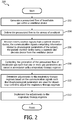
FIG. 2 illustrates amethod 200 for operating a ventilator device. The operations ofmethod 200 presented below are intended to be illustrative. In certain embodiments,method 200 may be accomplished with one or more additional operations not described, and/or without one or more of the operations discussed. Additionally, the order in which the operations ofmethod 200 are illustrated inFIG. 2 and described below is not intended to be limiting. - In certain aspects,
method 200 may be implemented in one or more processing devices (e.g., a digital processor, an analog processor, a digital circuit designed to process information, an analog circuit designed to process information, a state machine, and/or other mechanisms for electronically processing information). The one or more processing devices may include one or more devices executing some or all of the operations ofmethod 200 in response to instructions stored electronically on an electronic storage medium. The one or more processing devices may include one or more devices configured through hardware, firmware, and/or software to be specifically designed for execution of one or more of the operations ofmethod 200. - At an
operation 202, a pressurized flow of breathable gas is generated within a ventilator. In one embodiment,operation 202 is performed by a pressure generator similar to or substantially the same as pressure generator 140 (shown inFIG. 1 and described above). - At an
operation 204, the pressurized flow of breathable gas is delivered to the airway of a subject. In one embodiment,operation 204 is performed by an outlet or subject interface similar to or substantially the same as subject interface 180 (shown inFIG. 1 and described above). - At an
operation 206, communication signals are received from a patient monitor device. The communication signals comprise information related to physiological parameters of the subject. The patient monitor device is a separate and discrete device from the ventilator device. In one embodiment,operation 206 is performed by a communications transceiver similar to or substantially the same as communications transceiver 160 (shown inFIG. 1 and described above). - At an
operation 208, the generation of the pressurized flow of breathable gas is controlled such that one or more gas parameters of the pressurized flow of breathable gas are varied over time in accordance with a respiratory therapy regimen. In one embodiment,operation 208 is performed by a control module similar to or substantially the same as control module 112 (shown inFIG. 1 and described above). - At an
operation 210, adjustments are determined to the respiratory therapy regimen based on the communication signals received from the patient monitor device such that the physiological parameters are used for closed-loop control to adjust the respiratory therapy regimen. In one embodiment,operation 210 is performed by a regimen adjustment module similar to or substantially the same as regimen adjustment module 113 (shown inFIG. 1 and described above). - At an
operation 212, the adjustments to the respiratory therapy regimen are implemented. In one embodiment,operation 212 is performed by aregimen adjustment module 113 similar to or substantially the same as regimen adjustment module 113 (shown inFIG. 1 and described above). - In the claims, any reference signs placed between parentheses shall not be construed as limiting the claim. The word "comprising" or "including" does not exclude the presence of elements or steps other than those listed in a claim. In a device claim enumerating several means, several of these means may be embodied by one and the same item of hardware. The word "a" or "an" preceding an element does not exclude the presence of a plurality of such elements. In any device claim enumerating several means, several of these means may be embodied by one and the same item of hardware. The mere fact that certain elements are recited in mutually different dependent claims does not indicate that these elements cannot be used in combination.
- Although various embodiments have been described in detail for the purpose of illustration based on what is currently considered to be the most practical and preferred embodiments, it is to be understood that such detail is solely for that purpose and that the scope of this disclosure is not limited to the disclosed embodiments, but, on the contrary, is intended to cover modifications and equivalent arrangements that are within the scope of the appended claims. For example, it is to be understood that the present disclosure contemplates that, to the extent possible, one or more features of any embodiment can be combined with one or more features of any other embodiment.
Claims (5)
- A system comprising a ventilator (100) and a patient monitor device (150), wherein the patient monitor device (150) is a separate and discrete device from the ventilator (100), the ventilator comprising:a pressure generator (140) configured to generate a pressurized flow of breathable gas;a subject interface (180) configured to interface between the pressure generator and a breathing circuit to deliver the pressurized flow of breathable gas to the airway of a subject (106) through the subject interface;a communications transceiver (160) configured to receive communication signals from the patient monitor device, the communication signals comprising information related to physiological parameters of the subject;a plurality of ventilation sensors (142) configured to generate one or more output signals conveying measurements related to respiratory parameters of the subject (106);one or more processors (110) configured to execute processing modules, the processing modules comprising:a control module (112) configured to control the pressure generator such that one or more gas parameters of the pressurized flow of breathable gas are varied over time in accordance with a respiratory therapy regimen; anda regimen adjustment module (113) configured to determine adjustments to the respiratory therapy regimen based on the communication signals received from the patient monitor device such that the physiological parameters indicated in the communication signals are used for closed-loop control to adjust the respiratory therapy regimen,characterized in thatthe patient monitor device (150) includes one or more patient monitor sensors (143); wherein the patient monitor sensors (143) are configured to generate output signals conveying information related to the physiological parameters of the subject (106);the processing modules further comprising a parameter determination module configured to determine one or more parameters from the output signals generated by the plurality of ventilation sensors (142) and one or more patient monitor sensors (143), wherein executing of the processing modules is based on the simultaneous use of output signals generated by the ventilation sensors (142) and the patient monitor sensors (143).
- The system of claim 1, wherein the adjustments to the respiratory therapy regimen comprise adjustments to one or more of the gas parameters of the pressurized flow of breathable gas that are varied over time in accordance with the respiratory therapy regimen.
- The system of claim 1, wherein the respiratory therapy regimen is determined such that delivery of the pressurized flow of breathable gas to the airway of the subject controls one or more breathing parameters of the subject, and wherein the regimen adjustment module is configured to determine adjustments to the respiratory therapy regimen such that a breathing parameter of the subject is controlled based on the physiological parameters indicated in the communication signals.
- The system of claim 1, wherein the regimen adjustment module is configured to determine adjustments to the respiratory therapy regimen further based on the physiological parameters of the subject, wherein the adjustments pertain to control of one or more of nebulization, humidification, or inexsufflation.
- The system of claim 1, further comprising an external housing (170) that houses at least the pressure generator and the one or more processors.
Applications Claiming Priority (2)
| Application Number | Priority Date | Filing Date | Title |
|---|---|---|---|
| US201161527330P | 2011-08-25 | 2011-08-25 | |
| PCT/IB2012/054119 WO2013027151A1 (en) | 2011-08-25 | 2012-08-14 | Method and apparatus for controlling a ventilation therapy device |
Publications (2)
| Publication Number | Publication Date |
|---|---|
| EP2747817A1 EP2747817A1 (en) | 2014-07-02 |
| EP2747817B1 true EP2747817B1 (en) | 2018-10-10 |
Family
ID=47076291
Family Applications (1)
| Application Number | Title | Priority Date | Filing Date |
|---|---|---|---|
| EP12778417.1A Active EP2747817B1 (en) | 2011-08-25 | 2012-08-14 | Apparatus for controlling a ventilation therapy device |
Country Status (5)
| Country | Link |
|---|---|
| US (1) | US20140202455A1 (en) |
| EP (1) | EP2747817B1 (en) |
| JP (1) | JP6223340B2 (en) |
| CN (1) | CN103781507A (en) |
| WO (1) | WO2013027151A1 (en) |
Families Citing this family (13)
| Publication number | Priority date | Publication date | Assignee | Title |
|---|---|---|---|---|
| US20170224234A1 (en) * | 2014-10-16 | 2017-08-10 | Maquet Critical Care Ab | Modular monitoring and ventilation system |
| US20180133419A1 (en) * | 2015-05-07 | 2018-05-17 | Koninklijke Philips N.V. | Monitoring the degradation of a component of a patient interface device |
| EP3331594A1 (en) * | 2015-08-07 | 2018-06-13 | Koninklijke Philips N.V. | Cardiac, cardiopulmonary, and/or hemodynamic phenotyping |
| CN105148371B (en) * | 2015-11-03 | 2018-01-30 | 陈宏� | Intelligent domestic respirator system |
| CA3005443A1 (en) | 2015-11-16 | 2017-05-26 | Respirix, Inc. | Devices and methods for monitoring physiologic parameters |
| CN108290019B (en) * | 2015-12-01 | 2021-06-18 | 皇家飞利浦有限公司 | Method and apparatus for treating ataxic breathing |
| BR112020007200A2 (en) | 2017-10-19 | 2020-10-13 | Baxter International Inc. | optimized bedside security protocol system |
| US10803983B2 (en) * | 2017-10-27 | 2020-10-13 | Miraclebots, LLC | System and method for auto-regulating drug administration for achieving artificial homeostasis |
| CN110368561A (en) | 2019-06-03 | 2019-10-25 | 南京晨伟医疗设备有限公司 | A kind of ventilator intelligence system and its working method |
| GB2588757A (en) * | 2019-10-28 | 2021-05-12 | Buldeo Nitasha | Ventilator apparatus |
| CN112057713A (en) * | 2020-09-18 | 2020-12-11 | 德阳市人民医院 | Oxygen therapeutic machine capable of timing |
| CN113769213A (en) * | 2021-08-19 | 2021-12-10 | 北京怡和嘉业医疗科技股份有限公司 | Ventilation control method, device, system, terminal equipment and readable storage medium |
| US11642477B1 (en) * | 2022-05-17 | 2023-05-09 | Telesair, Inc. | Measurement device and method for monitoring condition of patient |
Family Cites Families (34)
| Publication number | Priority date | Publication date | Assignee | Title |
|---|---|---|---|---|
| US4387722A (en) * | 1978-11-24 | 1983-06-14 | Kearns Kenneth L | Respiration monitor and x-ray triggering apparatus |
| US5365922A (en) * | 1991-03-19 | 1994-11-22 | Brigham And Women's Hospital, Inc. | Closed-loop non-invasive oxygen saturation control system |
| US5353788A (en) * | 1992-09-21 | 1994-10-11 | Miles Laughton E | Cardio-respiratory control and monitoring system for determining CPAP pressure for apnea treatment |
| US6371114B1 (en) * | 1998-07-24 | 2002-04-16 | Minnesota Innovative Technologies & Instruments Corporation | Control device for supplying supplemental respiratory oxygen |
| GB2339933A (en) * | 1998-07-22 | 2000-02-09 | Ibm | Client/server computing with improved correspondence between transaction identifiers when supporting subordinate resource manager(s) |
| US7225809B1 (en) * | 1999-11-01 | 2007-06-05 | Ric Investments, Llc | Method and apparatus for monitoring and controlling a medical device |
| US7204250B1 (en) * | 1999-12-16 | 2007-04-17 | Compumedics Limited | Bio-mask |
| US7629890B2 (en) * | 2003-12-04 | 2009-12-08 | Hoana Medical, Inc. | System and methods for intelligent medical vigilance with bed exit detection |
| DE10116361A1 (en) * | 2001-04-02 | 2002-10-10 | Heptec Gmbh | Radio module, respirator, monitoring device therefor; Therapy device for carrying out CPAP therapy, monitoring device therefor; Systems and procedures |
| KR20050072435A (en) * | 2002-10-09 | 2005-07-11 | 컴퓨메딕스 리미티드 | Method and apparatus for maintaining and monitoring sleep quality during therapeutic treatments |
| GB2396426B (en) * | 2002-12-21 | 2005-08-24 | Draeger Medical Ag | Artificial respiration system |
| US7469697B2 (en) * | 2003-09-18 | 2008-12-30 | Cardiac Pacemakers, Inc. | Feedback system and method for sleep disordered breathing therapy |
| US7575005B2 (en) * | 2004-05-18 | 2009-08-18 | Excel-Tech Ltd. | Mask assembly with integrated sensors |
| US20060241708A1 (en) * | 2005-04-22 | 2006-10-26 | Willem Boute | Multiple sensors for sleep apnea with probability indication for sleep diagnosis and means for automatic activation of alert or therapy |
| US7527054B2 (en) * | 2005-05-24 | 2009-05-05 | General Electric Company | Apparatus and method for controlling fraction of inspired oxygen |
| CA2611603A1 (en) * | 2005-06-21 | 2007-01-04 | Ric Investments, Llc | Respiratory device measurement system |
| US7942824B1 (en) * | 2005-11-04 | 2011-05-17 | Cleveland Medical Devices Inc. | Integrated sleep diagnostic and therapeutic system and method |
| US8025052B2 (en) * | 2005-11-21 | 2011-09-27 | Ric Investments, Llc | System and method of monitoring respiratory events |
| US20070169779A1 (en) * | 2006-01-24 | 2007-07-26 | Freeman Gary A | Reperfusion protection in resuscitation |
| WO2007144767A2 (en) * | 2006-02-02 | 2007-12-21 | Be Eri Eliezer | A respiratory apparatus |
| US7810497B2 (en) * | 2006-03-20 | 2010-10-12 | Ric Investments, Llc | Ventilatory control system |
| US7922666B2 (en) * | 2006-09-21 | 2011-04-12 | Starr Life Sciences Corporation | Pulse oximeter based techniques for controlling anesthesia levels and ventilation levels in subjects |
| US8371299B2 (en) * | 2007-04-19 | 2013-02-12 | Respironics Respiratory Drug Delivery | Ventilator aerosol delivery |
| US8523758B1 (en) * | 2007-05-02 | 2013-09-03 | Ric Investments, Llc | System and method of treatment for insomnia and occasional sleeplessness |
| CN101618247B (en) * | 2008-07-03 | 2012-05-16 | 周常安 | Expansible gas delivery system |
| JP5415548B2 (en) * | 2008-11-07 | 2014-02-12 | コーニンクレッカ フィリップス エヌ ヴェ | Carbon dioxide monitoring system |
| US20100224192A1 (en) * | 2009-03-06 | 2010-09-09 | Cardinal Health 207, Inc. | Automated Oxygen Delivery Method |
| US8221319B2 (en) * | 2009-03-25 | 2012-07-17 | Nellcor Puritan Bennett Llc | Medical device for assessing intravascular blood volume and technique for using the same |
| JP6085835B2 (en) * | 2009-08-11 | 2017-03-08 | レスメド・モーター・テクノロジーズ・インコーポレーテッド | Single stage, axisymmetric blower and portable ventilator |
| US8960192B2 (en) * | 2009-09-01 | 2015-02-24 | Koninklijke Philips N.V. | System and method for quantifying lung compliance in a self-ventilating subject |
| CN102107037A (en) * | 2009-12-28 | 2011-06-29 | 周常安 | Air delivery system |
| EP2519296A4 (en) * | 2009-12-31 | 2015-03-11 | Eric N Doelling | Devices, systems, and methods for monitoring, analyzing, and/or adjusting sleep conditions |
| US8676285B2 (en) * | 2010-07-28 | 2014-03-18 | Covidien Lp | Methods for validating patient identity |
| US20120272955A1 (en) * | 2011-04-29 | 2012-11-01 | David Joseph Cool | Automatic Tracheostomy Suctioning and Nebulizer Medication Delivery System |
-
2012
- 2012-08-14 JP JP2014526575A patent/JP6223340B2/en active Active
- 2012-08-14 EP EP12778417.1A patent/EP2747817B1/en active Active
- 2012-08-14 CN CN201280041185.XA patent/CN103781507A/en active Pending
- 2012-08-14 US US14/239,225 patent/US20140202455A1/en not_active Abandoned
- 2012-08-14 WO PCT/IB2012/054119 patent/WO2013027151A1/en active Application Filing
Non-Patent Citations (1)
| Title |
|---|
| None * |
Also Published As
| Publication number | Publication date |
|---|---|
| CN103781507A (en) | 2014-05-07 |
| WO2013027151A1 (en) | 2013-02-28 |
| JP6223340B2 (en) | 2017-11-01 |
| US20140202455A1 (en) | 2014-07-24 |
| JP2014524326A (en) | 2014-09-22 |
| EP2747817A1 (en) | 2014-07-02 |
Similar Documents
| Publication | Publication Date | Title |
|---|---|---|
| EP2747817B1 (en) | Apparatus for controlling a ventilation therapy device | |
| US9987444B2 (en) | System and method for limited flow respiratory therapy | |
| EP2651478B1 (en) | System for customizable automated control of fraction of inspired oxygen and/or positive end expiratory pressure to maintain oxygenation | |
| JP6173320B2 (en) | Non-invasive ventilation measurement | |
| US10286165B2 (en) | Starting pressure for respiratory therapy devices | |
| EP2408502B1 (en) | System for adjusting tidal volume of a self-ventilating subject | |
| EP2717952B1 (en) | Configuration of respiratory therapy modes | |
| US9642976B2 (en) | Systems and methods for intra-pulmonary percussive ventilation integrated in a ventilator | |
| US10086157B2 (en) | System and method for improved compliance in respiratory therapy | |
| US20140326242A1 (en) | Sysems and methods for using partial co2 rebreathing integrated in a ventilator and measurements thereof to determine noninvasive cardiac output | |
| US11291786B2 (en) | Reducing hypercapnic respiratory failure during mechanical ventilation | |
| EP2685890B1 (en) | System to diagnose central sleep apnea | |
| EP2688620B1 (en) | Systems to manage central sleep apnea by controlling accumulated retrograde volume |
Legal Events
| Date | Code | Title | Description |
|---|---|---|---|
| PUAI | Public reference made under article 153(3) epc to a published international application that has entered the european phase |
Free format text: ORIGINAL CODE: 0009012 |
|
| 17P | Request for examination filed |
Effective date: 20140325 |
|
| AK | Designated contracting states |
Kind code of ref document: A1 Designated state(s): AL AT BE BG CH CY CZ DE DK EE ES FI FR GB GR HR HU IE IS IT LI LT LU LV MC MK MT NL NO PL PT RO RS SE SI SK SM TR |
|
| DAX | Request for extension of the european patent (deleted) | ||
| 17Q | First examination report despatched |
Effective date: 20160824 |
|
| STAA | Information on the status of an ep patent application or granted ep patent |
Free format text: STATUS: EXAMINATION IS IN PROGRESS |
|
| GRAP | Despatch of communication of intention to grant a patent |
Free format text: ORIGINAL CODE: EPIDOSNIGR1 |
|
| STAA | Information on the status of an ep patent application or granted ep patent |
Free format text: STATUS: GRANT OF PATENT IS INTENDED |
|
| INTG | Intention to grant announced |
Effective date: 20180306 |
|
| GRAS | Grant fee paid |
Free format text: ORIGINAL CODE: EPIDOSNIGR3 |
|
| GRAA | (expected) grant |
Free format text: ORIGINAL CODE: 0009210 |
|
| STAA | Information on the status of an ep patent application or granted ep patent |
Free format text: STATUS: THE PATENT HAS BEEN GRANTED |
|
| AK | Designated contracting states |
Kind code of ref document: B1 Designated state(s): AL AT BE BG CH CY CZ DE DK EE ES FI FR GB GR HR HU IE IS IT LI LT LU LV MC MK MT NL NO PL PT RO RS SE SI SK SM TR |
|
| REG | Reference to a national code |
Ref country code: GB Ref legal event code: FG4D |
|
| REG | Reference to a national code |
Ref country code: CH Ref legal event code: EP Ref country code: AT Ref legal event code: REF Ref document number: 1050510 Country of ref document: AT Kind code of ref document: T Effective date: 20181015 |
|
| REG | Reference to a national code |
Ref country code: IE Ref legal event code: FG4D |
|
| REG | Reference to a national code |
Ref country code: DE Ref legal event code: R096 Ref document number: 602012052064 Country of ref document: DE |
|
| REG | Reference to a national code |
Ref country code: NL Ref legal event code: MP Effective date: 20181010 |
|
| REG | Reference to a national code |
Ref country code: LT Ref legal event code: MG4D |
|
| REG | Reference to a national code |
Ref country code: AT Ref legal event code: MK05 Ref document number: 1050510 Country of ref document: AT Kind code of ref document: T Effective date: 20181010 |
|
| PG25 | Lapsed in a contracting state [announced via postgrant information from national office to epo] |
Ref country code: NL Free format text: LAPSE BECAUSE OF FAILURE TO SUBMIT A TRANSLATION OF THE DESCRIPTION OR TO PAY THE FEE WITHIN THE PRESCRIBED TIME-LIMIT Effective date: 20181010 |
|
| PG25 | Lapsed in a contracting state [announced via postgrant information from national office to epo] |
Ref country code: PL Free format text: LAPSE BECAUSE OF FAILURE TO SUBMIT A TRANSLATION OF THE DESCRIPTION OR TO PAY THE FEE WITHIN THE PRESCRIBED TIME-LIMIT Effective date: 20181010 Ref country code: LT Free format text: LAPSE BECAUSE OF FAILURE TO SUBMIT A TRANSLATION OF THE DESCRIPTION OR TO PAY THE FEE WITHIN THE PRESCRIBED TIME-LIMIT Effective date: 20181010 Ref country code: HR Free format text: LAPSE BECAUSE OF FAILURE TO SUBMIT A TRANSLATION OF THE DESCRIPTION OR TO PAY THE FEE WITHIN THE PRESCRIBED TIME-LIMIT Effective date: 20181010 Ref country code: AT Free format text: LAPSE BECAUSE OF FAILURE TO SUBMIT A TRANSLATION OF THE DESCRIPTION OR TO PAY THE FEE WITHIN THE PRESCRIBED TIME-LIMIT Effective date: 20181010 Ref country code: BG Free format text: LAPSE BECAUSE OF FAILURE TO SUBMIT A TRANSLATION OF THE DESCRIPTION OR TO PAY THE FEE WITHIN THE PRESCRIBED TIME-LIMIT Effective date: 20190110 Ref country code: IS Free format text: LAPSE BECAUSE OF FAILURE TO SUBMIT A TRANSLATION OF THE DESCRIPTION OR TO PAY THE FEE WITHIN THE PRESCRIBED TIME-LIMIT Effective date: 20190210 Ref country code: ES Free format text: LAPSE BECAUSE OF FAILURE TO SUBMIT A TRANSLATION OF THE DESCRIPTION OR TO PAY THE FEE WITHIN THE PRESCRIBED TIME-LIMIT Effective date: 20181010 Ref country code: NO Free format text: LAPSE BECAUSE OF FAILURE TO SUBMIT A TRANSLATION OF THE DESCRIPTION OR TO PAY THE FEE WITHIN THE PRESCRIBED TIME-LIMIT Effective date: 20190110 Ref country code: FI Free format text: LAPSE BECAUSE OF FAILURE TO SUBMIT A TRANSLATION OF THE DESCRIPTION OR TO PAY THE FEE WITHIN THE PRESCRIBED TIME-LIMIT Effective date: 20181010 Ref country code: LV Free format text: LAPSE BECAUSE OF FAILURE TO SUBMIT A TRANSLATION OF THE DESCRIPTION OR TO PAY THE FEE WITHIN THE PRESCRIBED TIME-LIMIT Effective date: 20181010 |
|
| PG25 | Lapsed in a contracting state [announced via postgrant information from national office to epo] |
Ref country code: SE Free format text: LAPSE BECAUSE OF FAILURE TO SUBMIT A TRANSLATION OF THE DESCRIPTION OR TO PAY THE FEE WITHIN THE PRESCRIBED TIME-LIMIT Effective date: 20181010 Ref country code: AL Free format text: LAPSE BECAUSE OF FAILURE TO SUBMIT A TRANSLATION OF THE DESCRIPTION OR TO PAY THE FEE WITHIN THE PRESCRIBED TIME-LIMIT Effective date: 20181010 Ref country code: RS Free format text: LAPSE BECAUSE OF FAILURE TO SUBMIT A TRANSLATION OF THE DESCRIPTION OR TO PAY THE FEE WITHIN THE PRESCRIBED TIME-LIMIT Effective date: 20181010 Ref country code: PT Free format text: LAPSE BECAUSE OF FAILURE TO SUBMIT A TRANSLATION OF THE DESCRIPTION OR TO PAY THE FEE WITHIN THE PRESCRIBED TIME-LIMIT Effective date: 20190210 Ref country code: GR Free format text: LAPSE BECAUSE OF FAILURE TO SUBMIT A TRANSLATION OF THE DESCRIPTION OR TO PAY THE FEE WITHIN THE PRESCRIBED TIME-LIMIT Effective date: 20190111 |
|
| REG | Reference to a national code |
Ref country code: DE Ref legal event code: R097 Ref document number: 602012052064 Country of ref document: DE |
|
| PG25 | Lapsed in a contracting state [announced via postgrant information from national office to epo] |
Ref country code: DK Free format text: LAPSE BECAUSE OF FAILURE TO SUBMIT A TRANSLATION OF THE DESCRIPTION OR TO PAY THE FEE WITHIN THE PRESCRIBED TIME-LIMIT Effective date: 20181010 Ref country code: IT Free format text: LAPSE BECAUSE OF FAILURE TO SUBMIT A TRANSLATION OF THE DESCRIPTION OR TO PAY THE FEE WITHIN THE PRESCRIBED TIME-LIMIT Effective date: 20181010 Ref country code: CZ Free format text: LAPSE BECAUSE OF FAILURE TO SUBMIT A TRANSLATION OF THE DESCRIPTION OR TO PAY THE FEE WITHIN THE PRESCRIBED TIME-LIMIT Effective date: 20181010 |
|
| PLBE | No opposition filed within time limit |
Free format text: ORIGINAL CODE: 0009261 |
|
| STAA | Information on the status of an ep patent application or granted ep patent |
Free format text: STATUS: NO OPPOSITION FILED WITHIN TIME LIMIT |
|
| PG25 | Lapsed in a contracting state [announced via postgrant information from national office to epo] |
Ref country code: RO Free format text: LAPSE BECAUSE OF FAILURE TO SUBMIT A TRANSLATION OF THE DESCRIPTION OR TO PAY THE FEE WITHIN THE PRESCRIBED TIME-LIMIT Effective date: 20181010 Ref country code: SM Free format text: LAPSE BECAUSE OF FAILURE TO SUBMIT A TRANSLATION OF THE DESCRIPTION OR TO PAY THE FEE WITHIN THE PRESCRIBED TIME-LIMIT Effective date: 20181010 Ref country code: EE Free format text: LAPSE BECAUSE OF FAILURE TO SUBMIT A TRANSLATION OF THE DESCRIPTION OR TO PAY THE FEE WITHIN THE PRESCRIBED TIME-LIMIT Effective date: 20181010 Ref country code: SK Free format text: LAPSE BECAUSE OF FAILURE TO SUBMIT A TRANSLATION OF THE DESCRIPTION OR TO PAY THE FEE WITHIN THE PRESCRIBED TIME-LIMIT Effective date: 20181010 |
|
| 26N | No opposition filed |
Effective date: 20190711 |
|
| PG25 | Lapsed in a contracting state [announced via postgrant information from national office to epo] |
Ref country code: SI Free format text: LAPSE BECAUSE OF FAILURE TO SUBMIT A TRANSLATION OF THE DESCRIPTION OR TO PAY THE FEE WITHIN THE PRESCRIBED TIME-LIMIT Effective date: 20181010 |
|
| PG25 | Lapsed in a contracting state [announced via postgrant information from national office to epo] |
Ref country code: TR Free format text: LAPSE BECAUSE OF FAILURE TO SUBMIT A TRANSLATION OF THE DESCRIPTION OR TO PAY THE FEE WITHIN THE PRESCRIBED TIME-LIMIT Effective date: 20181010 |
|
| PG25 | Lapsed in a contracting state [announced via postgrant information from national office to epo] |
Ref country code: MC Free format text: LAPSE BECAUSE OF FAILURE TO SUBMIT A TRANSLATION OF THE DESCRIPTION OR TO PAY THE FEE WITHIN THE PRESCRIBED TIME-LIMIT Effective date: 20181010 Ref country code: LI Free format text: LAPSE BECAUSE OF NON-PAYMENT OF DUE FEES Effective date: 20190831 Ref country code: CH Free format text: LAPSE BECAUSE OF NON-PAYMENT OF DUE FEES Effective date: 20190831 Ref country code: LU Free format text: LAPSE BECAUSE OF NON-PAYMENT OF DUE FEES Effective date: 20190814 |
|
| REG | Reference to a national code |
Ref country code: BE Ref legal event code: MM Effective date: 20190831 |
|
| PG25 | Lapsed in a contracting state [announced via postgrant information from national office to epo] |
Ref country code: IE Free format text: LAPSE BECAUSE OF NON-PAYMENT OF DUE FEES Effective date: 20190814 |
|
| PG25 | Lapsed in a contracting state [announced via postgrant information from national office to epo] |
Ref country code: BE Free format text: LAPSE BECAUSE OF NON-PAYMENT OF DUE FEES Effective date: 20190831 |
|
| PG25 | Lapsed in a contracting state [announced via postgrant information from national office to epo] |
Ref country code: CY Free format text: LAPSE BECAUSE OF FAILURE TO SUBMIT A TRANSLATION OF THE DESCRIPTION OR TO PAY THE FEE WITHIN THE PRESCRIBED TIME-LIMIT Effective date: 20181010 |
|
| PG25 | Lapsed in a contracting state [announced via postgrant information from national office to epo] |
Ref country code: HU Free format text: LAPSE BECAUSE OF FAILURE TO SUBMIT A TRANSLATION OF THE DESCRIPTION OR TO PAY THE FEE WITHIN THE PRESCRIBED TIME-LIMIT; INVALID AB INITIO Effective date: 20120814 Ref country code: MT Free format text: LAPSE BECAUSE OF FAILURE TO SUBMIT A TRANSLATION OF THE DESCRIPTION OR TO PAY THE FEE WITHIN THE PRESCRIBED TIME-LIMIT Effective date: 20181010 |
|
| PG25 | Lapsed in a contracting state [announced via postgrant information from national office to epo] |
Ref country code: MK Free format text: LAPSE BECAUSE OF FAILURE TO SUBMIT A TRANSLATION OF THE DESCRIPTION OR TO PAY THE FEE WITHIN THE PRESCRIBED TIME-LIMIT Effective date: 20181010 |
|
| PGFP | Annual fee paid to national office [announced via postgrant information from national office to epo] |
Ref country code: GB Payment date: 20230822 Year of fee payment: 12 |
|
| PGFP | Annual fee paid to national office [announced via postgrant information from national office to epo] |
Ref country code: FR Payment date: 20230824 Year of fee payment: 12 Ref country code: DE Payment date: 20230828 Year of fee payment: 12 |